EP4442803A1 - Endoscopic pipette and observation system - Google Patents
Endoscopic pipette and observation system Download PDFInfo
- Publication number
- EP4442803A1 EP4442803A1 EP22901748.8A EP22901748A EP4442803A1 EP 4442803 A1 EP4442803 A1 EP 4442803A1 EP 22901748 A EP22901748 A EP 22901748A EP 4442803 A1 EP4442803 A1 EP 4442803A1
- Authority
- EP
- European Patent Office
- Prior art keywords
- space
- pipette
- endoscopic
- unit
- image capturing
- Prior art date
- Legal status (The legal status is an assumption and is not a legal conclusion. Google has not performed a legal analysis and makes no representation as to the accuracy of the status listed.)
- Pending
Links
Images




Classifications
-
- C—CHEMISTRY; METALLURGY
- C12—BIOCHEMISTRY; BEER; SPIRITS; WINE; VINEGAR; MICROBIOLOGY; ENZYMOLOGY; MUTATION OR GENETIC ENGINEERING
- C12M—APPARATUS FOR ENZYMOLOGY OR MICROBIOLOGY; APPARATUS FOR CULTURING MICROORGANISMS FOR PRODUCING BIOMASS, FOR GROWING CELLS OR FOR OBTAINING FERMENTATION OR METABOLIC PRODUCTS, i.e. BIOREACTORS OR FERMENTERS
- C12M41/00—Means for regulation, monitoring, measurement or control, e.g. flow regulation
- C12M41/46—Means for regulation, monitoring, measurement or control, e.g. flow regulation of cellular or enzymatic activity or functionality, e.g. cell viability
-
- B—PERFORMING OPERATIONS; TRANSPORTING
- B01—PHYSICAL OR CHEMICAL PROCESSES OR APPARATUS IN GENERAL
- B01L—CHEMICAL OR PHYSICAL LABORATORY APPARATUS FOR GENERAL USE
- B01L3/00—Containers or dishes for laboratory use, e.g. laboratory glassware; Droppers
- B01L3/02—Burettes; Pipettes
- B01L3/021—Pipettes, i.e. with only one conduit for withdrawing and redistributing liquids
- B01L3/0217—Pipettes, i.e. with only one conduit for withdrawing and redistributing liquids of the plunger pump type
- B01L3/0237—Details of electronic control, e.g. relating to user interface
-
- C—CHEMISTRY; METALLURGY
- C12—BIOCHEMISTRY; BEER; SPIRITS; WINE; VINEGAR; MICROBIOLOGY; ENZYMOLOGY; MUTATION OR GENETIC ENGINEERING
- C12M—APPARATUS FOR ENZYMOLOGY OR MICROBIOLOGY; APPARATUS FOR CULTURING MICROORGANISMS FOR PRODUCING BIOMASS, FOR GROWING CELLS OR FOR OBTAINING FERMENTATION OR METABOLIC PRODUCTS, i.e. BIOREACTORS OR FERMENTERS
- C12M21/00—Bioreactors or fermenters specially adapted for specific uses
- C12M21/08—Bioreactors or fermenters specially adapted for specific uses for producing artificial tissue or for ex-vivo cultivation of tissue
-
- C—CHEMISTRY; METALLURGY
- C12—BIOCHEMISTRY; BEER; SPIRITS; WINE; VINEGAR; MICROBIOLOGY; ENZYMOLOGY; MUTATION OR GENETIC ENGINEERING
- C12M—APPARATUS FOR ENZYMOLOGY OR MICROBIOLOGY; APPARATUS FOR CULTURING MICROORGANISMS FOR PRODUCING BIOMASS, FOR GROWING CELLS OR FOR OBTAINING FERMENTATION OR METABOLIC PRODUCTS, i.e. BIOREACTORS OR FERMENTERS
- C12M23/00—Constructional details, e.g. recesses, hinges
- C12M23/50—Means for positioning or orientating the apparatus
-
- C—CHEMISTRY; METALLURGY
- C12—BIOCHEMISTRY; BEER; SPIRITS; WINE; VINEGAR; MICROBIOLOGY; ENZYMOLOGY; MUTATION OR GENETIC ENGINEERING
- C12M—APPARATUS FOR ENZYMOLOGY OR MICROBIOLOGY; APPARATUS FOR CULTURING MICROORGANISMS FOR PRODUCING BIOMASS, FOR GROWING CELLS OR FOR OBTAINING FERMENTATION OR METABOLIC PRODUCTS, i.e. BIOREACTORS OR FERMENTERS
- C12M29/00—Means for introduction, extraction or recirculation of materials, e.g. pumps
- C12M29/06—Nozzles; Sprayers; Spargers; Diffusers
-
- C—CHEMISTRY; METALLURGY
- C12—BIOCHEMISTRY; BEER; SPIRITS; WINE; VINEGAR; MICROBIOLOGY; ENZYMOLOGY; MUTATION OR GENETIC ENGINEERING
- C12M—APPARATUS FOR ENZYMOLOGY OR MICROBIOLOGY; APPARATUS FOR CULTURING MICROORGANISMS FOR PRODUCING BIOMASS, FOR GROWING CELLS OR FOR OBTAINING FERMENTATION OR METABOLIC PRODUCTS, i.e. BIOREACTORS OR FERMENTERS
- C12M33/00—Means for introduction, transport, positioning, extraction, harvesting, peeling or sampling of biological material in or from the apparatus
- C12M33/04—Means for introduction, transport, positioning, extraction, harvesting, peeling or sampling of biological material in or from the apparatus by injection or suction, e.g. using pipettes, syringes, needles
-
- C—CHEMISTRY; METALLURGY
- C12—BIOCHEMISTRY; BEER; SPIRITS; WINE; VINEGAR; MICROBIOLOGY; ENZYMOLOGY; MUTATION OR GENETIC ENGINEERING
- C12M—APPARATUS FOR ENZYMOLOGY OR MICROBIOLOGY; APPARATUS FOR CULTURING MICROORGANISMS FOR PRODUCING BIOMASS, FOR GROWING CELLS OR FOR OBTAINING FERMENTATION OR METABOLIC PRODUCTS, i.e. BIOREACTORS OR FERMENTERS
- C12M41/00—Means for regulation, monitoring, measurement or control, e.g. flow regulation
- C12M41/30—Means for regulation, monitoring, measurement or control, e.g. flow regulation of concentration
- C12M41/36—Means for regulation, monitoring, measurement or control, e.g. flow regulation of concentration of biomass, e.g. colony counters or by turbidity measurements
-
- B—PERFORMING OPERATIONS; TRANSPORTING
- B01—PHYSICAL OR CHEMICAL PROCESSES OR APPARATUS IN GENERAL
- B01L—CHEMICAL OR PHYSICAL LABORATORY APPARATUS FOR GENERAL USE
- B01L2200/00—Solutions for specific problems relating to chemical or physical laboratory apparatus
- B01L2200/02—Adapting objects or devices to another
- B01L2200/021—Adjust spacings in an array of wells, pipettes or holders, format transfer between arrays of different size or geometry
- B01L2200/022—Variable spacings
-
- B—PERFORMING OPERATIONS; TRANSPORTING
- B01—PHYSICAL OR CHEMICAL PROCESSES OR APPARATUS IN GENERAL
- B01L—CHEMICAL OR PHYSICAL LABORATORY APPARATUS FOR GENERAL USE
- B01L2300/00—Additional constructional details
- B01L2300/06—Auxiliary integrated devices, integrated components
- B01L2300/0627—Sensor or part of a sensor is integrated
- B01L2300/0663—Whole sensors
-
- B—PERFORMING OPERATIONS; TRANSPORTING
- B01—PHYSICAL OR CHEMICAL PROCESSES OR APPARATUS IN GENERAL
- B01L—CHEMICAL OR PHYSICAL LABORATORY APPARATUS FOR GENERAL USE
- B01L3/00—Containers or dishes for laboratory use, e.g. laboratory glassware; Droppers
- B01L3/02—Burettes; Pipettes
- B01L3/021—Pipettes, i.e. with only one conduit for withdrawing and redistributing liquids
Definitions
- the present invention relates to an endoscopic pipette and an observation system, and more particularly, to an endoscopic pipette and an observation system, which are capable of identifying states of spheroids in a culture vessel, which is difficult to visibly identify, and detecting motions of the spheroids during a process of extracting a culture medium, thereby preventing the spheroids from being lost.
- Spheroids which are produced by culturing cells, are too small to visibly observe sizes, shapes, and changes thereof. Therefore, microscopes may be used to observe the sizes, shapes, and changes of the spheroids.
- a culture medium in a culture vessel in which spheroids are cultured needs to be periodically replaced.
- a waste culture medium in the culture vessel, in which the spheroids are cultured, may be extracted, and a new culture medium may be supplied, such that the spheroids may be consistently grown to a desired degree.
- the culture medium may be lost, and the spheroids may be damaged while moving into the tip, which may result in wasted culture time.
- the present invention has been made in an effort to solve the above-mentioned problem in the related art, and an object of the present invention is to identify states of spheroids in a culture vessel, which is difficult to visibly identify, and detect motions of the spheroids during a process of extracting a culture medium, thereby preventing the spheroids from being lost.
- the present invention provides an endoscopic pipette and an observation system
- the endoscopic pipette is configured to remove a culture medium accommodated in a culture vessel, in which spheroids are cultured, and observe the spheroids in the culture vessel
- the endoscopic pipette includes: a tip unit configured to be inserted into the culture vessel to extract the culture medium; an accommodation unit configured to accommodate the culture medium extracted by the tip unit; a camera unit provided between the tip unit and the accommodation unit, disposed adjacent to the tip unit, and configured to capture an image of an interior of the culture vessel; and a power unit provided in a partial space of the accommodation unit and configured to provide power to the camera unit.
- the accommodation unit may be divided into a first space in which the culture medium introduced through the tip unit is accommodated, a second space in which the power unit is positioned, and a third space in which the camera unit is positioned.
- the second space may be disposed adjacent to the first space in which the culture medium is accommodated, and the second space may be elongated in a longitudinal direction of the accommodation unit.
- the power unit may include: a battery part configured to store electric power and provide the electric power to the camera unit; a switch part configured to operate the battery part; and a transmission part provided in the second space, disposed adjacent to the camera unit, and configured to transmit the image captured by the camera unit to the outside.
- the second space may be divided into three or more spaces so that the battery part, the switch part, and the transmission part are positioned in the separated spaces.
- the defined space of the second space, in which the battery part is positioned may be formed to be openable and closable so that the battery part is replaced depending on the amount of electric power remaining in the battery part.
- the third space may be disposed below the first space, and the tip unit may be coupled to penetrate the third space toward the first space.
- the tip unit may include: a through portion configured to penetrate the third space and having a constant diameter; and an extraction portion extending to the outside of the third space so that a diameter thereof decreases from the through portion toward the culture vessel, the extraction portion being inserted into the culture vessel to extract the culture medium.
- the camera unit may include: an image capturing part configured to capture an image of the interior of the culture vessel; and an adjustment part in which the image capturing part is positioned, the adjustment part being configured to move the image capturing part in a rotation direction.
- the adjustment part may include: a rotary member formed to surround a periphery of the image capturing part and partially exposed to the outside of the third space, the rotary member configured to move the image capturing part while rotating; a casing member having one end at which the rotary member is positioned, the casing member being configured to rotate in a rotation direction of the rotary member and configured such that a part of the image capturing part is inserted into the casing member; and a spring member having one end and the other end respectively coupled to the image capturing part and the casing member, the spring member being configured to move the image capturing part toward the culture vessel in accordance with the rotation of the rotary member.
- the camera unit may be provided as a pair of camera units positioned with the tip unit interposed therebetween.
- the camera unit may include an angle adj ustment part positioned between the pair of adjustment parts and configured to change an angle of the image capturing part while changing a distance between the other ends of the adjustment parts.
- the angle adjustment part may include: a serrated member having one end positioned outside the third space, and the other end positioned in the third space, the serrated member having a plurality of protrusions formed along a periphery of the other end; and a pair of distance members provided with the serrated member interposed therebetween, the pair of distance members having grooves corresponding to the protrusions of the serrated member and configured to be moved by a rotation of the serrated member.
- the present invention provides an observation system, which is configured to observe spheroids accommodated in a culture vessel, the observation system including: the endoscopic pipette; and a display configured to receive an image captured by the endoscopic pipette and display the image.
- the endoscopic pipette may transmit the image, which is captured by the image capturing part, to the display through the transmission part.
- the transmission part may be connected to the display through Bluetooth.
- the observation system may include a correction unit configured to correct a pair of images captured by a pair of image capturing parts so that the pair of images is visibly observed through binocular disparity.
- the endoscopic pipette and the observation system of the present invention provided to achieve the above-mentioned object may identify the states of the spheroids in the culture vessel, which is difficult to visibly identify, and detect the motions of the spheroids during the process of extracting the culture medium, thereby preventing the spheroids from being lost.
- FIG. 1 is a view for explaining an overall configuration of an endoscopic pipette and an observation device of an observation system according to an embodiment of the present invention
- FIG. 2 is a view for explaining a tip unit of the endoscopic pipette and the observation system according to the embodiment of the present invention
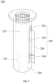
- FIG. 3 is a view for explaining an accommodation unit of the endoscopic pipette and the observation system according to the embodiment of the present invention
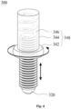
- FIG. 4 is a view for explaining a camera unit of the endoscopic pipette and the observation system according to the embodiment of the present invention
- FIG. 5 is a view for explaining an angle of a camera unit of the endoscopic pipette and the observation system according to the embodiment of the present invention
- FIG. 1 is a view for explaining an overall configuration of an endoscopic pipette and an observation device of an observation system according to an embodiment of the present invention
- FIG. 2 is a view for explaining a tip unit of the endoscopic pipette and the observation system according to the embodiment of the present invention
- FIG. 6 is a view for explaining a pair of camera units of the endoscopic pipette and the observation system according to the embodiment of the present invention
- FIG. 7 is a view for explaining an angle adjustment part of the endoscopic pipette and the observation system according to the embodiment of the present invention
- FIG. 8 is a view for explaining a serrated member and a distance member of the endoscopic pipette and the observation system according to the embodiment of the present invention
- FIG. 9 is a view for explaining a power unit of the endoscopic pipette and the observation system according to the embodiment of the present invention.
- a pipette 10 may be used to observe spheroids C in a culture vessel W while removing a culture medium accommodated in the culture vessel W in which the spheroids C are cultured.
- the pipette 10 may include a tip unit 100 configured to be inserted into the culture vessel W to extract the culture medium, an accommodation unit 200 configured to accommodate the culture medium extracted by the tip unit 100, a camera unit 300 provided between the tip unit 100 and the accommodation unit 200, disposed adjacent to the tip unit 100, and configured to capture an image of an interior of the culture vessel W, and a power unit 400 provided in a partial space of the accommodation unit 200 and configured to provide power to the camera unit 300.
- the tip unit 100 may be inserted into the culture vessel W to extract the culture medium in the culture vessel W.
- the tip unit 100 may be elongated from the accommodation unit 200 toward the culture vessel W.
- the tip unit 100 may include a through portion 120, an extraction portion 140, and a detachable portion 160.
- the through portion 120 may be disposed to penetrate a third space 260 defined in the accommodation unit 200 and communicate with a first space 220 of the accommodation unit 200. This configuration will be described more specifically with respect to the drawings to be described below in detail.
- the extraction portion 140 may be elongated from the accommodation unit 200 toward the culture vessel W and extend so that a diameter thereof gradually decreases. This configuration is to adjust a flow velocity of the culture medium that moves to the accommodation unit 200. Because the spheroid C is too small to visibly identify, one end of the extraction portion 140 may be formed to be narrow to extract only the culture medium, except for the spheroids C.
- the detachable portion 160 may be provided.
- the detachable portion 160 is formed to have a diameter corresponding to an outer diameter of the extraction portion 140 so that the extraction portion 140 is inserted into the detachable portion 160.
- the detachable portion 160 may be elongated toward the culture vessel W further than the extraction portion 140, such that one end of the detachable portion 160 has a smaller diameter than one end of the extraction portion 140.
- the detachable portion 160 may be formed to be detachable from one end of the extraction portion 140, and the extraction portion 140 and the detachable portion 160 may be formed to decrease in diameter toward one end.
- One end of the detachable portion 160 may be formed to have a relatively smaller diameter than one end of the extraction portion 140.
- the accommodation unit 200 may be divided into the first space 220 configured to accommodate the culture medium extracted by the tip unit 100, a second space 240 in which the power unit 400 is positioned, and the third space 260 formed to surround the through portion 120.
- first space 220, the second space 240, and the third space 260 may be spaces, which are separated so as not to interfere with one another, i.e., independent spaces that do not interfere with one another.
- the first space 220 accommodates the culture medium extracted by the tip unit 100
- the first space 220 may be formed to have a relatively larger volume than the second space 240 and the third space 260.
- the second space 240 may be disposed adjacent to the first space 220 and formed in a longitudinal direction of the accommodation unit 200.
- the second space 240 may include a first partition portion 242, a second partition portion 244, and a third partition portion 246 that may respectively define spaces separated from one another.
- a switch for operating a terminal part 440 of the power unit 400 or the camera unit 300 may be provided in the first partition portion 242.
- a battery part 420 which provides electric power to operate the camera unit 300, may be disposed in the second partition portion 244.
- An opening/closing part 280 may be disposed in the second partition portion 244 and configured to selectively open or close the second partition portion 244 so that the battery part 420 may be replaced, as necessary.
- opening/closing part 280 may also be disposed in the third partition portion 246.
- a transmission part 12 may be disposed in the third partition portion 246 and configured to transmit images, which are captured by the camera unit 300, to the outside.
- the camera unit 300, the power unit 400, the transmission part 12, and the like will be described more specifically with reference to the drawings.
- the third space 260 may provide a space in which the camera unit 300 is disposed.
- the third space 260 may be provided between the first space 220 and the second space 240 and between the second space 240 and the tip unit 100, and the through portion 120 may be disposed in the third space 260.
- the third space may be formed to surround a part of the tip unit 100 and define a space in which the camera unit 300 is disposed.
- the accommodation unit 200 may be divided into two or more separate spaces and divided into the first space 220, the second space 240, and the third space 260 depending on the types of components accommodated therein.
- the first space 220 may accommodate the culture medium extracted by the tip unit 100
- the second space 240 may accommodate the power unit 400
- the third space 260 may accommodate the camera unit 300 therein.
- the second space 240 may be divided again into a plurality of separated spaces and divided into the first partition portion 242, the second partition portion 244, and the third partition portion 246 depending on the objects accommodated therein.
- the camera unit 300 may be provided in the third space 260 and disposed adjacent to the through portion 120. As illustrated in FIG. 4 , the camera unit 300 may include an image capturing part 320 configured to capture images of the spheroids C in the culture vessel W, and an adjustment part 340 configured to adjust sizes of the spheroids C, which are to be observed, on a screen by adjusting a position of the image capturing part 320.
- the image capturing part 320 may be connected to the transmission part 12 electrically or through near-field communication such as Bluetooth.
- the image capturing part 320 may use a visibly expandable lens such as an endoscope camera or a microscope in order to identify the spheroids C that are difficult to visibly identify.
- the adjustment part 340 may simply adjust the position of the image capturing part 320 to perform a zoom-in or zoom-out function.
- the adjustment part 340 may include a rotary member 342 configured to change a position of the image capturing part 320 while rotating, a casing member 344 having one end at which the rotary member 342 is positioned, the casing member 344 being configured such that a part of the image capturing part 320 is inserted into the casing member 344, and a spring member 346 having one end and the other end respectively coupled to the casing member 344 and the image capturing part 320, the spring member 346 being configured to transmit a rotational force of the rotary member 342 and move the image capturing part 320.
- the rotary member 342 may be formed so that a part of the third space 260 is exposed to the outside. Therefore, a user may adjust a position of the image capturing part 320 by rotating the rotary member 342 exposed to the outside.
- a space may be defined in the casing member 344, and the image capturing part 320 may move in the casing member 344 and rotate in a rotation direction of the rotary member 342.
- one end and the other end of the spring member 346 may be respectively connected to the image capturing part 320 and the casing member 344, and one end and the other end of the spring member 346 may move away from or toward each other in the rotation direction of the casing member 344 that rotates together with the rotary member 342 in the direction in which the rotary member 342 rotates, such that the image capturing part 320 may be moved, and the zoom-in or zoom-out function may be performed.
- the image capturing part 320 may be provided in the third space 260 and inclined at a preset angle, and the preset angle may correspond to an inclination of an outer periphery of the tip unit 100.
- the pair of camera units 300 may be provided to be inclined by the preset angle along the inclination of the tip unit 100 and capture images of one end of the tip unit 100.
- the pair of camera units 300 may be used to effectively observe and determine the interior of the culture vessel W in which the spheroids C are accommodated.
- the pipette may further include an angle adjustment part 360 configured to change an angle of the camera unit 300, as necessary.
- the angle adjustment part 360 may be disposed adjacent to the through portion 120 and provided between the pair of camera units 300.
- angle adjustment part 360 may be coupled to ends of the pair of camera units 300, such that an angle at which the image capturing part 320 captures images may be adjusted by adjusting a distance between the ends of the pair of camera units 300.
- the angle adjustment part 360 may be coupled to the casing member 340.
- the angle adjustment part 360 may include a serrated member 362 having one end protruding outward, like the rotary member 342, and the other end having a plurality of protrusions along a periphery thereof, and a pair of distance members 364 provided with the serrated member 362 interposed therebetween, the pair of distance members 364 having protrusions, which have shapes corresponding to the periphery of the serrated member 362, and configured to be moved by a rotation of the serrated member 362.
- the pair of distance members 364 may be moved in opposite directions by means of the protrusions that engage with one another in response to the rotation of the serrated member 362, such that the distance between the ends of the camera units 300 may be adjusted.
- the binocular disparity may be more easily used by adjusting angles at which the camera units 300 capture images by adjusting the distance between the pair of camera units 300. Therefore, it is possible to more assuredly identify whether the spheroids C are lost during the process of extracting the culture medium by means of the tip unit 100.
- the power unit 400 may include the battery part 420 positioned in the second space 240, elongated in one direction, and configured to provide electric power to the camera unit 300, the terminal part 440 connected to an external terminal to supply electric power to the battery part 420, and the transmission part 12 configured to transmit images, which are captured by the camera units 300, to the outside.
- the battery part 420 may be disposed to be replaceable and replaced by the opening/closing part 280 configured to selectively open the second partition portion 244.
- the battery part 420 may be electrically connected to the camera unit 300 and the transmission part 12.
- a switch part may be provided to selectively operate the battery part 420.
- the switch part may be provided in the first partition portion 242 and electrically connected to the battery part 420.
- the terminal part 440 may mean a position into which a terminal is inserted to charge the battery part 420, which has consumed electric power, with electric power in a state in which the battery part 420 is replaced.
- the terminal part 440 may be provided at a part of a periphery of the battery part 420.
- the transmission part 12 may be electrically connected to the image capturing part 320.
- the transmission part 12 may be connected to the image capturing part 320 through near-field communication such as Bluetooth and transmit images, which are captured by the image capturing part 320, to the outside.
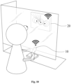
- FIG. 10 is a view for explaining the endoscopic pipette and the observation system according to the embodiment of the present invention.
- the user may extract the culture medium or observe the spheroids C by using the pipette 10 including the tip unit 100, the accommodation unit 200, the camera unit 300, and the power unit 400.
- the transmission part 12 may transmit the images, which are captured by the image capturing part 320, to the outside.
- the observation system of the present invention may include the pipette 10 and a display 20 configured to display the images transmitted from the transmission part 12, and the images transmitted from the transmission part 12 are enlarged and displayed on the display 20, such that the user may more effectively identify the images visibly.
- the transmission part 12 and the display 20 may be connected to each other electrically or through near-field communication.
- the transmission part 12 and the display 20 may be connected to each other through Bluetooth.
- the electrical connection may affect a movement range of the pipette 10 and cause an unexpected accident in which the culture vessel W is touched by an electric wire or the like used to electrically connect the pipette 10 and the display 20.
- the connection through wireless communication may be preferable in comparison with the electrical connection.
- the display 20 may be equipped with a correction unit for correcting the images transmitted from the transmission part 12.
- the correction unit may three-dimensionally correct the images captured by the different camera units 300 into a single image and display the single image on the display 20.
- the correction unit may edit and correct the plurality of images transmitted from the transmission part 12 and exhibit an effect equivalent to viewing the culture vessel W with a single camera. Therefore, the user may visibly identify the spheroids C, which is difficult to visibly identify, and identify the motions of the spheroids C during the process of extracting the culture medium, which may effectively prevent a loss of the spheroids C.
Landscapes
- Health & Medical Sciences (AREA)
- Chemical & Material Sciences (AREA)
- Life Sciences & Earth Sciences (AREA)
- Engineering & Computer Science (AREA)
- Bioinformatics & Cheminformatics (AREA)
- Wood Science & Technology (AREA)
- Organic Chemistry (AREA)
- Zoology (AREA)
- Genetics & Genomics (AREA)
- Biomedical Technology (AREA)
- General Health & Medical Sciences (AREA)
- Microbiology (AREA)
- Biochemistry (AREA)
- General Engineering & Computer Science (AREA)
- Sustainable Development (AREA)
- Biotechnology (AREA)
- Clinical Laboratory Science (AREA)
- Chemical Kinetics & Catalysis (AREA)
- Analytical Chemistry (AREA)
- Human Computer Interaction (AREA)
- Molecular Biology (AREA)
- Cell Biology (AREA)
- Microscoopes, Condenser (AREA)
- Investigating Materials By The Use Of Optical Means Adapted For Particular Applications (AREA)
- Eye Examination Apparatus (AREA)
- Geophysics And Detection Of Objects (AREA)
Abstract
Description
- The present invention relates to an endoscopic pipette and an observation system, and more particularly, to an endoscopic pipette and an observation system, which are capable of identifying states of spheroids in a culture vessel, which is difficult to visibly identify, and detecting motions of the spheroids during a process of extracting a culture medium, thereby preventing the spheroids from being lost.
- Spheroids, which are produced by culturing cells, are too small to visibly observe sizes, shapes, and changes thereof. Therefore, microscopes may be used to observe the sizes, shapes, and changes of the spheroids.
- However, a culture medium in a culture vessel in which spheroids are cultured, needs to be periodically replaced. A waste culture medium in the culture vessel, in which the spheroids are cultured, may be extracted, and a new culture medium may be supplied, such that the spheroids may be consistently grown to a desired degree.
- However, when the spheroids are moved into a tip by a suction force applied to the tip to extract the culture medium during the process of extracting the waste culture medium, the culture medium may be lost, and the spheroids may be damaged while moving into the tip, which may result in wasted culture time.
- Therefore, a method has been proposed to consistently and smoothly identify cultured states of spheroids and minimize a loss of the spheroids during the process of extracting the culture medium, and a means for implementing the method is required.
- The present invention has been made in an effort to solve the above-mentioned problem in the related art, and an object of the present invention is to identify states of spheroids in a culture vessel, which is difficult to visibly identify, and detect motions of the spheroids during a process of extracting a culture medium, thereby preventing the spheroids from being lost.
- Technical problems of the present invention are not limited to the aforementioned technical problems, and other technical problems, which are not mentioned above, may be clearly understood by those skilled in the art from the following descriptions.
- In order to achieve the above-mentioned object, the present invention provides an endoscopic pipette and an observation system, the endoscopic pipette is configured to remove a culture medium accommodated in a culture vessel, in which spheroids are cultured, and observe the spheroids in the culture vessel, and the endoscopic pipette includes: a tip unit configured to be inserted into the culture vessel to extract the culture medium; an accommodation unit configured to accommodate the culture medium extracted by the tip unit; a camera unit provided between the tip unit and the accommodation unit, disposed adjacent to the tip unit, and configured to capture an image of an interior of the culture vessel; and a power unit provided in a partial space of the accommodation unit and configured to provide power to the camera unit.
- In this case, the accommodation unit may be divided into a first space in which the culture medium introduced through the tip unit is accommodated, a second space in which the power unit is positioned, and a third space in which the camera unit is positioned.
- In this case, the second space may be disposed adjacent to the first space in which the culture medium is accommodated, and the second space may be elongated in a longitudinal direction of the accommodation unit.
- Further, the power unit may include: a battery part configured to store electric power and provide the electric power to the camera unit; a switch part configured to operate the battery part; and a transmission part provided in the second space, disposed adjacent to the camera unit, and configured to transmit the image captured by the camera unit to the outside.
- In addition, the second space may be divided into three or more spaces so that the battery part, the switch part, and the transmission part are positioned in the separated spaces.
- Further, the defined space of the second space, in which the battery part is positioned, may be formed to be openable and closable so that the battery part is replaced depending on the amount of electric power remaining in the battery part.
- Meanwhile, the third space may be disposed below the first space, and the tip unit may be coupled to penetrate the third space toward the first space.
- In this case, the tip unit may include: a through portion configured to penetrate the third space and having a constant diameter; and an extraction portion extending to the outside of the third space so that a diameter thereof decreases from the through portion toward the culture vessel, the extraction portion being inserted into the culture vessel to extract the culture medium.
- Meanwhile, the camera unit may include: an image capturing part configured to capture an image of the interior of the culture vessel; and an adjustment part in which the image capturing part is positioned, the adjustment part being configured to move the image capturing part in a rotation direction.
- In this case, the adjustment part may include: a rotary member formed to surround a periphery of the image capturing part and partially exposed to the outside of the third space, the rotary member configured to move the image capturing part while rotating; a casing member having one end at which the rotary member is positioned, the casing member being configured to rotate in a rotation direction of the rotary member and configured such that a part of the image capturing part is inserted into the casing member; and a spring member having one end and the other end respectively coupled to the image capturing part and the casing member, the spring member being configured to move the image capturing part toward the culture vessel in accordance with the rotation of the rotary member.
- In addition, the camera unit may be provided as a pair of camera units positioned with the tip unit interposed therebetween.
- Further, the camera unit may include an angle adj ustment part positioned between the pair of adjustment parts and configured to change an angle of the image capturing part while changing a distance between the other ends of the adjustment parts.
- In addition, the angle adjustment part may include: a serrated member having one end positioned outside the third space, and the other end positioned in the third space, the serrated member having a plurality of protrusions formed along a periphery of the other end; and a pair of distance members provided with the serrated member interposed therebetween, the pair of distance members having grooves corresponding to the protrusions of the serrated member and configured to be moved by a rotation of the serrated member.
- Meanwhile, the present invention provides an observation system, which is configured to observe spheroids accommodated in a culture vessel, the observation system including: the endoscopic pipette; and a display configured to receive an image captured by the endoscopic pipette and display the image.
- In this case, the endoscopic pipette may transmit the image, which is captured by the image capturing part, to the display through the transmission part.
- In addition, the transmission part may be connected to the display through Bluetooth.
- Further, the observation system may include a correction unit configured to correct a pair of images captured by a pair of image capturing parts so that the pair of images is visibly observed through binocular disparity.
- The endoscopic pipette and the observation system of the present invention provided to achieve the above-mentioned object may identify the states of the spheroids in the culture vessel, which is difficult to visibly identify, and detect the motions of the spheroids during the process of extracting the culture medium, thereby preventing the spheroids from being lost.
- The effects of the present invention are not limited to the aforementioned effects, and other effects, which are not mentioned above, will be clearly understood by those skilled in the art from the claims.
- A detailed description of the exemplary embodiments of the present application to be described below as well as the summary explained above will be understood well when reading the detailed description and the summary with reference to the accompanying drawings.
- The exemplary embodiments are illustrated in the drawings for the purpose of exemplifying the present invention.
- However, it should be understood that the present application is not limited to the illustrated exact arrangement and means.
-
FIG. 1 is a view for explaining an overall configuration of an endoscopic pipette and an observation device of an observation system according to an embodiment of the present invention. -
FIG. 2 is a view for explaining a tip unit of the endoscopic pipette and the observation system according to the embodiment of the present invention. -
FIG. 3 is a view for explaining an accommodation unit of the endoscopic pipette and the observation system according to the embodiment of the present invention. -
FIG. 4 is a view for explaining a camera unit of the endoscopic pipette and the observation system according to the embodiment of the present invention. -
FIG. 5 is a view for explaining an angle of a camera unit of the endoscopic pipette and the observation system according to the embodiment of the present invention. -
FIG. 6 is a view for explaining a pair of camera units of the endoscopic pipette and the observation system according to the embodiment of the present invention. -
FIG. 7 is a view for explaining an angle adjustment part of the endoscopic pipette and the observation system according to the embodiment of the present invention. -
FIG. 8 is a view for explaining a serrated member and a distance member of the endoscopic pipette and the observation system according to the embodiment of the present invention. -
FIG. 9 is a view for explaining a power unit of the endoscopic pipette and the observation system according to the embodiment of the present invention. -
FIG. 10 is a view for explaining the endoscopic pipette and the observation system according to the embodiment of the present invention. -
- C:
- Spheroid
- W:
- Culture vessel
- 10:
- Pipette
- 12:
- Transmission part
- 20:
- Display
- 100:
- Tip unit
- 120:
- Through portion
- 140:
- Extraction portion
- 160:
- Needle part
- 200:
- Accommodation unit
- 220:
- First space
- 240:
- Second space
- 242:
- First partition portion
- 244:
- Second partition portion
- 246:
- Third partition portion
- 260:
- Third space
- 280:
- Opening/closing part
- 300:
- Camera unit
- 320:
- Image capturing part
- 340:
- Adjustment part
- 342:
- Rotary member
- 344:
- Casing member
- 360:
- Angle adjustment part
- 362:
- Serrated member
- 364:
- Distance member
- 400:
- Power unit
- 420:
- Battery part
- 440:
- Terminal part
- Hereinafter, exemplary embodiments of the present invention for specifically accomplishing the objects of the present invention will be described with reference to the accompanying drawings.
- In the description of the present embodiments, like terms and like reference numerals are used for like configurations, and additional descriptions for the like configurations will be omitted.
- First, an endoscopic pipette according to an embodiment of the present invention will be described with reference to
FIGS. 1 to 9 . - Specifically,
FIG. 1 is a view for explaining an overall configuration of an endoscopic pipette and an observation device of an observation system according to an embodiment of the present invention,FIG. 2 is a view for explaining a tip unit of the endoscopic pipette and the observation system according to the embodiment of the present invention,FIG. 3 is a view for explaining an accommodation unit of the endoscopic pipette and the observation system according to the embodiment of the present invention,FIG. 4 is a view for explaining a camera unit of the endoscopic pipette and the observation system according to the embodiment of the present invention,FIG. 5 is a view for explaining an angle of a camera unit of the endoscopic pipette and the observation system according to the embodiment of the present invention,FIG. 6 is a view for explaining a pair of camera units of the endoscopic pipette and the observation system according to the embodiment of the present invention,FIG. 7 is a view for explaining an angle adjustment part of the endoscopic pipette and the observation system according to the embodiment of the present invention,FIG. 8 is a view for explaining a serrated member and a distance member of the endoscopic pipette and the observation system according to the embodiment of the present invention, andFIG. 9 is a view for explaining a power unit of the endoscopic pipette and the observation system according to the embodiment of the present invention. - First, as illustrated in
FIG. 1 , apipette 10 may be used to observe spheroids C in a culture vessel W while removing a culture medium accommodated in the culture vessel W in which the spheroids C are cultured. Thepipette 10 may include atip unit 100 configured to be inserted into the culture vessel W to extract the culture medium, anaccommodation unit 200 configured to accommodate the culture medium extracted by thetip unit 100, acamera unit 300 provided between thetip unit 100 and theaccommodation unit 200, disposed adjacent to thetip unit 100, and configured to capture an image of an interior of the culture vessel W, and apower unit 400 provided in a partial space of theaccommodation unit 200 and configured to provide power to thecamera unit 300. - In this case, the
tip unit 100 may be inserted into the culture vessel W to extract the culture medium in the culture vessel W. Thetip unit 100 may be elongated from theaccommodation unit 200 toward the culture vessel W. - In this case, as illustrated in
FIG. 2 , thetip unit 100 may include a throughportion 120, anextraction portion 140, and adetachable portion 160. - In this case, the through
portion 120 may be disposed to penetrate athird space 260 defined in theaccommodation unit 200 and communicate with afirst space 220 of theaccommodation unit 200. This configuration will be described more specifically with respect to the drawings to be described below in detail. - Further, the
extraction portion 140 may be elongated from theaccommodation unit 200 toward the culture vessel W and extend so that a diameter thereof gradually decreases. This configuration is to adjust a flow velocity of the culture medium that moves to theaccommodation unit 200. Because the spheroid C is too small to visibly identify, one end of theextraction portion 140 may be formed to be narrow to extract only the culture medium, except for the spheroids C. - Meanwhile, the spheroids C may be sucked and lost in case that a diameter of one end of the
extraction portion 140 is relatively large even though theextraction portion 140 is inserted into the culture vessel W to extract the culture medium. In order to prevent this situation, thedetachable portion 160 may be provided. Thedetachable portion 160 is formed to have a diameter corresponding to an outer diameter of theextraction portion 140 so that theextraction portion 140 is inserted into thedetachable portion 160. Thedetachable portion 160 may be elongated toward the culture vessel W further than theextraction portion 140, such that one end of thedetachable portion 160 has a smaller diameter than one end of theextraction portion 140. - This is to adjust a flow velocity and the amount of the culture medium sucked during the process of extracting the culture medium in the culture vessel W or to allow the detachable portion to have a smaller diameter than the
extraction portion 140 to minimize a loss of the spheroids C. - That is, the
detachable portion 160 may be formed to be detachable from one end of theextraction portion 140, and theextraction portion 140 and thedetachable portion 160 may be formed to decrease in diameter toward one end. One end of thedetachable portion 160 may be formed to have a relatively smaller diameter than one end of theextraction portion 140. - Meanwhile, as illustrated in
FIG. 3 , theaccommodation unit 200 may be divided into thefirst space 220 configured to accommodate the culture medium extracted by thetip unit 100, asecond space 240 in which thepower unit 400 is positioned, and thethird space 260 formed to surround the throughportion 120. - In this case, the
first space 220, thesecond space 240, and thethird space 260 may be spaces, which are separated so as not to interfere with one another, i.e., independent spaces that do not interfere with one another. - In this case, because the
first space 220 accommodates the culture medium extracted by thetip unit 100, thefirst space 220 may be formed to have a relatively larger volume than thesecond space 240 and thethird space 260. - Meanwhile, the
second space 240 may be disposed adjacent to thefirst space 220 and formed in a longitudinal direction of theaccommodation unit 200. - Further, as illustrated in
FIG. 3 , thesecond space 240 may include afirst partition portion 242, asecond partition portion 244, and athird partition portion 246 that may respectively define spaces separated from one another. - In this case, a switch for operating a
terminal part 440 of thepower unit 400 or thecamera unit 300 may be provided in thefirst partition portion 242. - In addition, a
battery part 420, which provides electric power to operate thecamera unit 300, may be disposed in thesecond partition portion 244. An opening/closing part 280 may be disposed in thesecond partition portion 244 and configured to selectively open or close thesecond partition portion 244 so that thebattery part 420 may be replaced, as necessary. - Further, the opening/
closing part 280 may also be disposed in thethird partition portion 246. Atransmission part 12 may be disposed in thethird partition portion 246 and configured to transmit images, which are captured by thecamera unit 300, to the outside. Thecamera unit 300, thepower unit 400, thetransmission part 12, and the like will be described more specifically with reference to the drawings. - Meanwhile, the
third space 260 may provide a space in which thecamera unit 300 is disposed. Thethird space 260 may be provided between thefirst space 220 and thesecond space 240 and between thesecond space 240 and thetip unit 100, and the throughportion 120 may be disposed in thethird space 260. - That is, the third space may be formed to surround a part of the
tip unit 100 and define a space in which thecamera unit 300 is disposed. - The above-mentioned configuration will be described simply. The
accommodation unit 200 may be divided into two or more separate spaces and divided into thefirst space 220, thesecond space 240, and thethird space 260 depending on the types of components accommodated therein. Thefirst space 220 may accommodate the culture medium extracted by thetip unit 100, thesecond space 240 may accommodate thepower unit 400, and thethird space 260 may accommodate thecamera unit 300 therein. - In addition, the
second space 240 may be divided again into a plurality of separated spaces and divided into thefirst partition portion 242, thesecond partition portion 244, and thethird partition portion 246 depending on the objects accommodated therein. - Meanwhile, the
camera unit 300 may be provided in thethird space 260 and disposed adjacent to the throughportion 120. As illustrated inFIG. 4 , thecamera unit 300 may include animage capturing part 320 configured to capture images of the spheroids C in the culture vessel W, and anadjustment part 340 configured to adjust sizes of the spheroids C, which are to be observed, on a screen by adjusting a position of theimage capturing part 320. - In this case, the
image capturing part 320 may be connected to thetransmission part 12 electrically or through near-field communication such as Bluetooth. Theimage capturing part 320 may use a visibly expandable lens such as an endoscope camera or a microscope in order to identify the spheroids C that are difficult to visibly identify. - Meanwhile, the
adjustment part 340 may simply adjust the position of theimage capturing part 320 to perform a zoom-in or zoom-out function. Theadjustment part 340 may include arotary member 342 configured to change a position of theimage capturing part 320 while rotating, acasing member 344 having one end at which therotary member 342 is positioned, thecasing member 344 being configured such that a part of theimage capturing part 320 is inserted into thecasing member 344, and aspring member 346 having one end and the other end respectively coupled to thecasing member 344 and theimage capturing part 320, thespring member 346 being configured to transmit a rotational force of therotary member 342 and move theimage capturing part 320. - In this case, the
rotary member 342 may be formed so that a part of thethird space 260 is exposed to the outside. Therefore, a user may adjust a position of theimage capturing part 320 by rotating therotary member 342 exposed to the outside. - Further, a space may be defined in the
casing member 344, and theimage capturing part 320 may move in thecasing member 344 and rotate in a rotation direction of therotary member 342. - In addition, one end and the other end of the
spring member 346 may be respectively connected to theimage capturing part 320 and thecasing member 344, and one end and the other end of thespring member 346 may move away from or toward each other in the rotation direction of thecasing member 344 that rotates together with therotary member 342 in the direction in which therotary member 342 rotates, such that theimage capturing part 320 may be moved, and the zoom-in or zoom-out function may be performed. - Further, as illustrated in
FIG. 5 , theimage capturing part 320 may be provided in thethird space 260 and inclined at a preset angle, and the preset angle may correspond to an inclination of an outer periphery of thetip unit 100. - This is to identify whether the spheroids C are sucked into the
tip unit 100 in a direction in which one end of thetip unit 100 is directed. - That is, it is possible to identify a peripheral portion of one end of the
tip unit 100. - Meanwhile, as illustrated in
FIG. 6 , in case that thecamera unit 300 is provided as a pair ofcamera units 300 provided based on the throughportion 120, the pair ofcamera units 300 may be provided to be inclined by the preset angle along the inclination of thetip unit 100 and capture images of one end of thetip unit 100. - This may be because it is generally more accurate to recognize an object with two visual fields than with a single visual field, and better able to can effectively determine distances and three-dimensions.
- More specifically, in general, when perceiving objects with the single eye, there are problems such as unfamiliarity with the position and distance of the objects in comparison with the visual perception of the objects through the single eye, and a decrease in the sense of distance between the objects, as well as a decrease in the sense of three-dimensionality, which makes the size of the objects smaller than the tactile sense. In contrast, when utilizing binocular disparity, the stereoscopic and distance senses of the objects are higher than when using the single eye. Therefore, the pair of
camera units 300 may be used to effectively observe and determine the interior of the culture vessel W in which the spheroids C are accommodated. - Meanwhile, because the observation accuracy is determined depending on an angle defined between the pair of
camera units 300 in case that the pair ofcamera units 300 is used, the pipette may further include anangle adjustment part 360 configured to change an angle of thecamera unit 300, as necessary. - In this case, as illustrated in
FIG. 7 , theangle adjustment part 360 may be disposed adjacent to the throughportion 120 and provided between the pair ofcamera units 300. - Further, the
angle adjustment part 360 may be coupled to ends of the pair ofcamera units 300, such that an angle at which theimage capturing part 320 captures images may be adjusted by adjusting a distance between the ends of the pair ofcamera units 300. - More specifically, as illustrated in
FIG. 8 , theangle adjustment part 360 may be coupled to thecasing member 340. Theangle adjustment part 360 may include aserrated member 362 having one end protruding outward, like therotary member 342, and the other end having a plurality of protrusions along a periphery thereof, and a pair ofdistance members 364 provided with theserrated member 362 interposed therebetween, the pair ofdistance members 364 having protrusions, which have shapes corresponding to the periphery of theserrated member 362, and configured to be moved by a rotation of theserrated member 362. - When one end of the
serrated member 362 is rotated, the pair ofdistance members 364 may be moved in opposite directions by means of the protrusions that engage with one another in response to the rotation of theserrated member 362, such that the distance between the ends of thecamera units 300 may be adjusted. - As described above, the binocular disparity may be more easily used by adjusting angles at which the
camera units 300 capture images by adjusting the distance between the pair ofcamera units 300. Therefore, it is possible to more assuredly identify whether the spheroids C are lost during the process of extracting the culture medium by means of thetip unit 100. - Meanwhile, as illustrated in
FIG. 9 , thepower unit 400 may include thebattery part 420 positioned in thesecond space 240, elongated in one direction, and configured to provide electric power to thecamera unit 300, theterminal part 440 connected to an external terminal to supply electric power to thebattery part 420, and thetransmission part 12 configured to transmit images, which are captured by thecamera units 300, to the outside. - In this case, as described above, the
battery part 420 may be disposed to be replaceable and replaced by the opening/closing part 280 configured to selectively open thesecond partition portion 244. Thebattery part 420 may be electrically connected to thecamera unit 300 and thetransmission part 12. - Further, a switch part may be provided to selectively operate the
battery part 420. As described above, the switch part may be provided in thefirst partition portion 242 and electrically connected to thebattery part 420. - Meanwhile, the
terminal part 440 may mean a position into which a terminal is inserted to charge thebattery part 420, which has consumed electric power, with electric power in a state in which thebattery part 420 is replaced. Theterminal part 440 may be provided at a part of a periphery of thebattery part 420. - Meanwhile, the
transmission part 12 may be electrically connected to theimage capturing part 320. However, as described above, thetransmission part 12 may be connected to theimage capturing part 320 through near-field communication such as Bluetooth and transmit images, which are captured by theimage capturing part 320, to the outside. - In order to more specifically describe the above-mentioned configuration, an observation system according to the embodiment of the present invention may be described with reference to
FIG. 10 . - Specifically,
FIG. 10 is a view for explaining the endoscopic pipette and the observation system according to the embodiment of the present invention. - In this case, as illustrated in
FIG. 10 , the user may extract the culture medium or observe the spheroids C by using thepipette 10 including thetip unit 100, theaccommodation unit 200, thecamera unit 300, and thepower unit 400. When the images captured by theimage capturing part 320, which captures images of the interior of the culture vessel W, are transmitted to thetransmission part 12 through wireless communication, thetransmission part 12 may transmit the images, which are captured by theimage capturing part 320, to the outside. - In this case, the observation system of the present invention may include the
pipette 10 and adisplay 20 configured to display the images transmitted from thetransmission part 12, and the images transmitted from thetransmission part 12 are enlarged and displayed on thedisplay 20, such that the user may more effectively identify the images visibly. - Further, like the
transmission part 12 connected to thecamera unit 300 electrically or through wireless communication, thetransmission part 12 and thedisplay 20 may be connected to each other electrically or through near-field communication. For example, thetransmission part 12 and thedisplay 20 may be connected to each other through Bluetooth. - However, the electrical connection may affect a movement range of the
pipette 10 and cause an unexpected accident in which the culture vessel W is touched by an electric wire or the like used to electrically connect thepipette 10 and thedisplay 20. The connection through wireless communication may be preferable in comparison with the electrical connection. - Meanwhile, as described above, in case that the pair of
camera units 300 is provided, thedisplay 20 may be equipped with a correction unit for correcting the images transmitted from thetransmission part 12. The correction unit may three-dimensionally correct the images captured by thedifferent camera units 300 into a single image and display the single image on thedisplay 20. - That is, the correction unit may edit and correct the plurality of images transmitted from the
transmission part 12 and exhibit an effect equivalent to viewing the culture vessel W with a single camera. Therefore, the user may visibly identify the spheroids C, which is difficult to visibly identify, and identify the motions of the spheroids C during the process of extracting the culture medium, which may effectively prevent a loss of the spheroids C. - While the exemplary embodiments according to the present invention have been described above, it is obvious to those skilled in the art that the present invention may be specified in other particular forms in addition to the aforementioned embodiments without departing from the spirit or the scope of the present invention.
- Accordingly, it should be understood that the aforementioned embodiments are not restrictive but illustrative, and thus the present invention is not limited to the aforementioned description, and may be modified within the scope of the appended claims and the equivalent range thereto.
Claims (17)
- An endoscopic pipette, which is configured to remove a culture medium accommodated in a culture vessel, in which spheroids are cultured, and observe the spheroids in the culture vessel, the endoscopic pipette comprising:a tip unit configured to be inserted into the culture vessel to extract the culture medium;an accommodation unit configured to accommodate the culture medium extracted by the tip unit;a camera unit provided between the tip unit and the accommodation unit, disposed adjacent to the tip unit, and configured to capture an image of an interior of the culture vessel; anda power unit provided in a partial space of the accommodation unit and configured to provide power to the camera unit.
- The endoscopic pipette of claim 1, wherein the accommodation unit is divided into a first space in which the culture medium introduced through the tip unit is accommodated, a second space in which the power unit is positioned, and a third space in which the camera unit is positioned.
- The endoscopic pipette of claim 2, wherein the second space is disposed adjacent to the first space in which the culture medium is accommodated, and the second space is elongated in a longitudinal direction of the accommodation unit.
- The endoscopic pipette of claim 3, wherein the power unit comprises:a battery part configured to store electric power and provide the electric power to the camera unit;a switch part configured to operate the battery part; anda transmission part provided in the second space, disposed adjacent to the camera unit, and configured to transmit the image captured by the camera unit to the outside.
- The endoscopic pipette of claim 4, wherein the second space is divided into three or more spaces so that the battery part, the switch part, and the transmission part are positioned in the separated spaces.
- The endoscopic pipette of claim 5, wherein the defined space of the second space, in which the battery part is positioned, is formed to be openable and closable so that the battery part is replaced depending on the amount of electric power remaining in the battery part.
- The endoscopic pipette of claim 2, wherein the third space is disposed below the first space, and the tip unit is coupled to penetrate the third space toward the first space.
- The endoscopic pipette of claim 7, wherein the tip unit comprises:a through portion configured to penetrate the third space and having a constant diameter; andan extraction portion extending to the outside of the third space so that a diameter thereof decreases from the through portion toward the culture vessel, the extraction portion being inserted into the culture vessel to extract the culture medium.
- The endoscopic pipette of claim 2, wherein the camera unit comprises:an image capturing part configured to capture an image of the interior of the culture vessel; andan adjustment part in which the image capturing part is positioned, the adjustment part being configured to move the image capturing part in a rotation direction.
- The endoscopic pipette of claim 9, wherein the adjustment part comprises:a rotary member formed to surround a periphery of the image capturing part and partially exposed to the outside of the third space, the rotary member configured to move the image capturing part while rotating;a casing member having one end at which the rotary member is positioned, the casing member being configured to rotate in a rotation direction of the rotary member and configured such that a part of the image capturing part is inserted into the casing member; anda spring member having one end and the other end respectively coupled to the image capturing part and the casing member, the spring member being configured to move the image capturing part toward the culture vessel in accordance with the rotation of the rotary member.
- The endoscopic pipette of claim 10, wherein the camera unit is provided as a pair of camera units positioned with the tip unit interposed therebetween.
- The endoscopic pipette of claim 11, wherein the camera unit comprises an angle adjustment part positioned between the pair of adjustment parts and configured to change an angle of the image capturing part while changing a distance between the other ends of the adjustment parts.
- The endoscopic pipette of claim 12, wherein the angle adjustment part comprises:a serrated member having one end positioned outside the third space, and the other end positioned in the third space, the serrated member having a plurality of protrusions formed along a periphery of the other end; anda pair of distance members provided with the serrated member interposed therebetween, the pair of distance members having grooves corresponding to the protrusions of the serrated member and configured to be moved by a rotation of the serrated member.
- An observation system, which is configured to observe spheroids accommodated in a culture vessel, the observation system comprising:the endoscopic pipette of any one of claims 1 to 13; anda display configured to receive an image captured by the endoscopic pipette and display the image.
- The observation system of claim 14, wherein the endoscopic pipette transmits the image, which is captured by the image capturing part, to the display through the transmission part.
- The observation system of claim 15, wherein the transmission part is connected to the display through Bluetooth.
- The observation system of claim 15, comprising:
a correction unit configured to correct a pair of images captured by a pair of image capturing parts so that the pair of images is visibly observed through binocular disparity.
Applications Claiming Priority (2)
| Application Number | Priority Date | Filing Date | Title |
|---|---|---|---|
| KR1020210168532A KR102623346B1 (en) | 2021-11-30 | 2021-11-30 | Spheroid observation device and observation system |
| PCT/KR2022/019161 WO2023101390A1 (en) | 2021-11-30 | 2022-11-30 | Endoscopic pipette and observation system |
Publications (2)
| Publication Number | Publication Date |
|---|---|
| EP4442803A1 true EP4442803A1 (en) | 2024-10-09 |
| EP4442803A4 EP4442803A4 (en) | 2025-10-29 |
Family
ID=86612617
Family Applications (1)
| Application Number | Title | Priority Date | Filing Date |
|---|---|---|---|
| EP22901748.8A Pending EP4442803A4 (en) | 2021-11-30 | 2022-11-30 | ENDOSCOPIC PIPETTE AND OBSERVATION SYSTEM |
Country Status (4)
| Country | Link |
|---|---|
| US (1) | US20250025871A1 (en) |
| EP (1) | EP4442803A4 (en) |
| KR (1) | KR102623346B1 (en) |
| WO (1) | WO2023101390A1 (en) |
Family Cites Families (11)
| Publication number | Priority date | Publication date | Assignee | Title |
|---|---|---|---|---|
| US4967606A (en) * | 1988-04-29 | 1990-11-06 | Caveo Scientific Instruments, Inc. | Method and apparatus for pipetting liquids |
| US6254832B1 (en) * | 1999-03-05 | 2001-07-03 | Rainin Instrument Co., Inc. | Battery powered microprocessor controlled hand portable electronic pipette |
| DE10130621B4 (en) * | 2001-06-26 | 2005-07-28 | Carl Zeiss Jena Gmbh | microscope |
| KR200333583Y1 (en) * | 2003-07-28 | 2003-11-14 | 김영실 | Divice for fat aspirator |
| US20090055131A1 (en) * | 2005-04-20 | 2009-02-26 | Shmuel Bukshpan | Automatic recording volume measurement apparatus |
| KR101064213B1 (en) * | 2009-03-03 | 2011-09-14 | 이남수 | Mobile phones with telescopes with angle and distance adjustment means |
| US8876707B2 (en) * | 2010-09-03 | 2014-11-04 | Alexander Wellen | Hand-held ear vacuum with camera and video display |
| EP2919067B1 (en) * | 2014-03-12 | 2017-10-18 | Ram Srikanth Mirlay | Multi-planar camera apparatus |
| US10112192B2 (en) * | 2014-06-10 | 2018-10-30 | Thermo Fisher Scientific Oy | Pipette comprising imaging device element |
| KR101734940B1 (en) * | 2015-10-29 | 2017-05-15 | 한국생산기술연구원 | Observing Device Having Sliding Separated Needle Unit |
| US9639935B1 (en) * | 2016-05-25 | 2017-05-02 | Gopro, Inc. | Apparatus and methods for camera alignment model calibration |
-
2021
- 2021-11-30 KR KR1020210168532A patent/KR102623346B1/en active Active
-
2022
- 2022-11-30 EP EP22901748.8A patent/EP4442803A4/en active Pending
- 2022-11-30 WO PCT/KR2022/019161 patent/WO2023101390A1/en not_active Ceased
- 2022-11-30 US US18/713,858 patent/US20250025871A1/en active Pending
Also Published As
| Publication number | Publication date |
|---|---|
| EP4442803A4 (en) | 2025-10-29 |
| KR102623346B1 (en) | 2024-01-11 |
| WO2023101390A1 (en) | 2023-06-08 |
| KR20230080937A (en) | 2023-06-07 |
| US20250025871A1 (en) | 2025-01-23 |
Similar Documents
| Publication | Publication Date | Title |
|---|---|---|
| US20220265125A1 (en) | Wireless swivel camera laparoscopic instrument with a virtual mapping and guidance system | |
| US9526407B2 (en) | Wirelessly powered medical devices and instruments | |
| CN110622500B (en) | Imaging apparatus and imaging method | |
| JP5430666B2 (en) | Endoscope system | |
| US8712228B2 (en) | Intraoral camera for dental chairs | |
| US9686468B2 (en) | Imaging apparatus | |
| EP2454987A2 (en) | Capsule guiding system | |
| US20140002630A1 (en) | Endoscopic apparatus and measuring method | |
| US20100179384A1 (en) | Wirelessly Powered Medical Devices And Instruments | |
| EP3637757B1 (en) | Image processing device, image processing method, and program | |
| CN103841880A (en) | Method and apparatus for hysteroscopy and endometrial biopsy | |
| CN101652092A (en) | Endoscope system, imaging system, and image processing apparatus | |
| EP2727513A1 (en) | Solid state variable direction of view endoscope with rotatable wide-angle field for maximal image performance | |
| US20250025871A1 (en) | Endoscopic pipette and observation system | |
| EP3590438A1 (en) | Medical display-control device, medical observation device, display-control method, and medical observation system | |
| CN102599876B (en) | Endoscope having automatic positioning and viewing unit | |
| US11925326B1 (en) | Portable handheld endoscopic image and video capture and display system | |
| US7312923B2 (en) | View field frame position adjustable optical device | |
| US12292563B2 (en) | Endoscope system having a display control apparatus, a detection apparatus, and a probe | |
| US10292620B1 (en) | Stereo imaging acquisition by lens translation | |
| CN107249425B (en) | Endoscopic device | |
| US20140088353A1 (en) | Stereo endoscope apparatus and image processing method in stereo endoscope apparatus | |
| JP2009198787A (en) | Endoscopic device | |
| KR20120138520A (en) | Operation microscope system | |
| JP2017006156A (en) | Living body forceps and observation system |
Legal Events
| Date | Code | Title | Description |
|---|---|---|---|
| STAA | Information on the status of an ep patent application or granted ep patent |
Free format text: STATUS: THE INTERNATIONAL PUBLICATION HAS BEEN MADE |
|
| PUAI | Public reference made under article 153(3) epc to a published international application that has entered the european phase |
Free format text: ORIGINAL CODE: 0009012 |
|
| STAA | Information on the status of an ep patent application or granted ep patent |
Free format text: STATUS: REQUEST FOR EXAMINATION WAS MADE |
|
| 17P | Request for examination filed |
Effective date: 20240619 |
|
| AK | Designated contracting states |
Kind code of ref document: A1 Designated state(s): AL AT BE BG CH CY CZ DE DK EE ES FI FR GB GR HR HU IE IS IT LI LT LU LV MC ME MK MT NL NO PL PT RO RS SE SI SK SM TR |
|
| DAV | Request for validation of the european patent (deleted) | ||
| DAX | Request for extension of the european patent (deleted) | ||
| A4 | Supplementary search report drawn up and despatched |
Effective date: 20250930 |
|
| RIC1 | Information provided on ipc code assigned before grant |
Ipc: C12M 1/34 20060101AFI20250924BHEP Ipc: C12M 1/00 20060101ALI20250924BHEP Ipc: B01L 3/02 20060101ALI20250924BHEP Ipc: C12M 3/00 20060101ALI20250924BHEP Ipc: C12M 1/26 20060101ALI20250924BHEP |