EP4440893B1 - Ausfallsicheres redundantes bremssystem mit druckeinspeisung über einen entlüftungspfad des primären modulators - Google Patents
Ausfallsicheres redundantes bremssystem mit druckeinspeisung über einen entlüftungspfad des primären modulators Download PDFInfo
- Publication number
- EP4440893B1 EP4440893B1 EP22805903.6A EP22805903A EP4440893B1 EP 4440893 B1 EP4440893 B1 EP 4440893B1 EP 22805903 A EP22805903 A EP 22805903A EP 4440893 B1 EP4440893 B1 EP 4440893B1
- Authority
- EP
- European Patent Office
- Prior art keywords
- redundancy
- brake pressure
- port
- valve
- brake
- Prior art date
- Legal status (The legal status is an assumption and is not a legal conclusion. Google has not performed a legal analysis and makes no representation as to the accuracy of the status listed.)
- Active
Links
Images
Classifications
-
- B—PERFORMING OPERATIONS; TRANSPORTING
- B60—VEHICLES IN GENERAL
- B60T—VEHICLE BRAKE CONTROL SYSTEMS OR PARTS THEREOF; BRAKE CONTROL SYSTEMS OR PARTS THEREOF, IN GENERAL; ARRANGEMENT OF BRAKING ELEMENTS ON VEHICLES IN GENERAL; PORTABLE DEVICES FOR PREVENTING UNWANTED MOVEMENT OF VEHICLES; VEHICLE MODIFICATIONS TO FACILITATE COOLING OF BRAKES
- B60T17/00—Component parts, details, or accessories of power brake systems not covered by groups B60T8/00, B60T13/00 or B60T15/00, or presenting other characteristic features
- B60T17/18—Safety devices; Monitoring
-
- B—PERFORMING OPERATIONS; TRANSPORTING
- B60—VEHICLES IN GENERAL
- B60T—VEHICLE BRAKE CONTROL SYSTEMS OR PARTS THEREOF; BRAKE CONTROL SYSTEMS OR PARTS THEREOF, IN GENERAL; ARRANGEMENT OF BRAKING ELEMENTS ON VEHICLES IN GENERAL; PORTABLE DEVICES FOR PREVENTING UNWANTED MOVEMENT OF VEHICLES; VEHICLE MODIFICATIONS TO FACILITATE COOLING OF BRAKES
- B60T13/00—Transmitting braking action from initiating means to ultimate brake actuator with power assistance or drive; Brake systems incorporating such transmitting means, e.g. air-pressure brake systems
- B60T13/10—Transmitting braking action from initiating means to ultimate brake actuator with power assistance or drive; Brake systems incorporating such transmitting means, e.g. air-pressure brake systems with fluid assistance, drive, or release
- B60T13/66—Electrical control in fluid-pressure brake systems
- B60T13/662—Electrical control in fluid-pressure brake systems characterised by specified functions of the control system components
-
- B—PERFORMING OPERATIONS; TRANSPORTING
- B60—VEHICLES IN GENERAL
- B60T—VEHICLE BRAKE CONTROL SYSTEMS OR PARTS THEREOF; BRAKE CONTROL SYSTEMS OR PARTS THEREOF, IN GENERAL; ARRANGEMENT OF BRAKING ELEMENTS ON VEHICLES IN GENERAL; PORTABLE DEVICES FOR PREVENTING UNWANTED MOVEMENT OF VEHICLES; VEHICLE MODIFICATIONS TO FACILITATE COOLING OF BRAKES
- B60T13/00—Transmitting braking action from initiating means to ultimate brake actuator with power assistance or drive; Brake systems incorporating such transmitting means, e.g. air-pressure brake systems
- B60T13/10—Transmitting braking action from initiating means to ultimate brake actuator with power assistance or drive; Brake systems incorporating such transmitting means, e.g. air-pressure brake systems with fluid assistance, drive, or release
- B60T13/66—Electrical control in fluid-pressure brake systems
- B60T13/665—Electrical control in fluid-pressure brake systems the systems being specially adapted for transferring two or more command signals, e.g. railway systems
-
- B—PERFORMING OPERATIONS; TRANSPORTING
- B60—VEHICLES IN GENERAL
- B60T—VEHICLE BRAKE CONTROL SYSTEMS OR PARTS THEREOF; BRAKE CONTROL SYSTEMS OR PARTS THEREOF, IN GENERAL; ARRANGEMENT OF BRAKING ELEMENTS ON VEHICLES IN GENERAL; PORTABLE DEVICES FOR PREVENTING UNWANTED MOVEMENT OF VEHICLES; VEHICLE MODIFICATIONS TO FACILITATE COOLING OF BRAKES
- B60T13/00—Transmitting braking action from initiating means to ultimate brake actuator with power assistance or drive; Brake systems incorporating such transmitting means, e.g. air-pressure brake systems
- B60T13/10—Transmitting braking action from initiating means to ultimate brake actuator with power assistance or drive; Brake systems incorporating such transmitting means, e.g. air-pressure brake systems with fluid assistance, drive, or release
- B60T13/66—Electrical control in fluid-pressure brake systems
- B60T13/68—Electrical control in fluid-pressure brake systems by electrically-controlled valves
- B60T13/683—Electrical control in fluid-pressure brake systems by electrically-controlled valves in pneumatic systems or parts thereof
-
- B—PERFORMING OPERATIONS; TRANSPORTING
- B60—VEHICLES IN GENERAL
- B60T—VEHICLE BRAKE CONTROL SYSTEMS OR PARTS THEREOF; BRAKE CONTROL SYSTEMS OR PARTS THEREOF, IN GENERAL; ARRANGEMENT OF BRAKING ELEMENTS ON VEHICLES IN GENERAL; PORTABLE DEVICES FOR PREVENTING UNWANTED MOVEMENT OF VEHICLES; VEHICLE MODIFICATIONS TO FACILITATE COOLING OF BRAKES
- B60T7/00—Brake-action initiating means
- B60T7/12—Brake-action initiating means for automatic initiation; for initiation not subject to will of driver or passenger
- B60T7/20—Brake-action initiating means for automatic initiation; for initiation not subject to will of driver or passenger specially for trailers, e.g. in case of uncoupling of or overrunning by trailer
-
- B—PERFORMING OPERATIONS; TRANSPORTING
- B60—VEHICLES IN GENERAL
- B60T—VEHICLE BRAKE CONTROL SYSTEMS OR PARTS THEREOF; BRAKE CONTROL SYSTEMS OR PARTS THEREOF, IN GENERAL; ARRANGEMENT OF BRAKING ELEMENTS ON VEHICLES IN GENERAL; PORTABLE DEVICES FOR PREVENTING UNWANTED MOVEMENT OF VEHICLES; VEHICLE MODIFICATIONS TO FACILITATE COOLING OF BRAKES
- B60T8/00—Arrangements for adjusting wheel-braking force to meet varying vehicular or ground-surface conditions, e.g. limiting or varying distribution of braking force
- B60T8/18—Arrangements for adjusting wheel-braking force to meet varying vehicular or ground-surface conditions, e.g. limiting or varying distribution of braking force responsive to vehicle weight or load, e.g. load distribution
- B60T8/1887—Arrangements for adjusting wheel-braking force to meet varying vehicular or ground-surface conditions, e.g. limiting or varying distribution of braking force responsive to vehicle weight or load, e.g. load distribution especially adapted for tractor-trailer combinations
-
- B—PERFORMING OPERATIONS; TRANSPORTING
- B60—VEHICLES IN GENERAL
- B60T—VEHICLE BRAKE CONTROL SYSTEMS OR PARTS THEREOF; BRAKE CONTROL SYSTEMS OR PARTS THEREOF, IN GENERAL; ARRANGEMENT OF BRAKING ELEMENTS ON VEHICLES IN GENERAL; PORTABLE DEVICES FOR PREVENTING UNWANTED MOVEMENT OF VEHICLES; VEHICLE MODIFICATIONS TO FACILITATE COOLING OF BRAKES
- B60T8/00—Arrangements for adjusting wheel-braking force to meet varying vehicular or ground-surface conditions, e.g. limiting or varying distribution of braking force
- B60T8/32—Arrangements for adjusting wheel-braking force to meet varying vehicular or ground-surface conditions, e.g. limiting or varying distribution of braking force responsive to a speed condition, e.g. acceleration or deceleration
- B60T8/321—Arrangements for adjusting wheel-braking force to meet varying vehicular or ground-surface conditions, e.g. limiting or varying distribution of braking force responsive to a speed condition, e.g. acceleration or deceleration deceleration
- B60T8/323—Systems specially adapted for tractor-trailer combinations
-
- B—PERFORMING OPERATIONS; TRANSPORTING
- B60—VEHICLES IN GENERAL
- B60T—VEHICLE BRAKE CONTROL SYSTEMS OR PARTS THEREOF; BRAKE CONTROL SYSTEMS OR PARTS THEREOF, IN GENERAL; ARRANGEMENT OF BRAKING ELEMENTS ON VEHICLES IN GENERAL; PORTABLE DEVICES FOR PREVENTING UNWANTED MOVEMENT OF VEHICLES; VEHICLE MODIFICATIONS TO FACILITATE COOLING OF BRAKES
- B60T2270/00—Further aspects of brake control systems not otherwise provided for
- B60T2270/40—Failsafe aspects of brake control systems
- B60T2270/413—Plausibility monitoring, cross check, redundancy
Definitions
- the invention relates to an electronically controllable pneumatic braking system for a vehicle, preferably a commercial vehicle, comprising an electronic operating control unit and at least one first brake pressure modulator, which is connected to a first compressed air supply for receiving supply pressure and which, depending on first service brake signals provided by the electronic operating control unit, controls a first service brake pressure at at least one first service brake pressure connection.
- the first brake pressure modulator has a first vent connection for venting the first service brake pressure.
- the braking system further comprises an electronic redundancy control unit and at least one first redundancy pressure modulator, which is connected to the first compressed air supply or to another compressed air supply for receiving supply pressure and which, depending on first redundancy brake signals provided by the electronic redundancy control unit, controls a first redundancy brake pressure at at least one first redundancy brake pressure connection.
- the first redundancy pressure modulator has a first redundancy vent port for venting the first redundancy brake pressure.
- DE 10 2016 005 318 A1 an electronically controllable pneumatic braking system with at least two brake circuits, wherein at least one of the at least two brake circuits is assigned an electrically and pneumatically controllable control valve and another of the at least two brake circuits is assigned an electrically controllable parking brake valve for specifying brake pressures for actuating wheel brakes of the respective brake circuit.
- a first control unit is provided, which is designed to electrically actuate the respective control valve as a function of an automatically requested target vehicle deceleration or an actuation specified by the driver via a brake pedal.
- a second control unit which is designed to electrically control the parking brake valve as a function of the automatically requested target vehicle deceleration if electrical actuation of the respective control valve is prevented, in order to form an electronically pneumatically controlled redundancy.
- a bypass valve is provided which is assigned to one of the control valves and is designed to pneumatically control the assigned control valve, wherein the pneumatic control takes place as a function of the automatically requested vehicle target deceleration or as a function of the actuation of the brake pedal by the driver if electrical control of the respective control valve is prevented.
- the object of the present invention is therefore to further improve the existing systems, which basically function well, and to achieve high availability while at the same time providing flow-technically advantageous solutions that have less or no impact on the primary system.
- the invention solves the problem in an electronically controllable pneumatic brake system of the type mentioned at the outset in that the first redundancy brake pressure connection of the redundancy pressure modulator is connected to the first venting connection of the first brake pressure modulator, so that the first redundancy brake pressure can be controlled via a first venting path of the first brake pressure modulator at the first service brake pressure connection of the first brake pressure modulator.
- the invention is based on the finding that the venting path of a modulator is available even in the event of a serious fault. Unlike a redundancy connection of a modulator, which is dependent on the availability of a main actuator of the modulator because, for example, a control pressure output at the redundancy connection initially acts on a control surface of a relay valve in order to increase the volume of this control pressure, a control of the brake pressure via the venting path does not require such an actuator and can generally be used even in the event of a faulty relay valve. Unlike usual with a redundancy connection, according to The invention provides that the first redundancy pressure modulator controls a first redundancy brake pressure, specifically a volume pressure, not merely a control pressure that still requires volume amplification.
- the redundancy brake pressure is controlled through the venting path of the first brake pressure modulator and provided, preferably unmodulated, at the first service brake pressure connection. Furthermore, no select-high valve is required to supply the redundancy brake pressure and service brake pressure alternately or as needed to the brake actuator. In this way, a structural simplification of the solution known from the prior art is achieved, while at the same time increasing stability and availability and optimizing the flow situation.
- the first brake pressure modulator can, for example, be provided for a front axle and thus be referred to as a front axle modulator. It can also be provided for a rear axle and be referred to as a rear axle modulator.
- the first service brake pressure would then be a front axle service brake pressure in the former case, and a rear axle service brake pressure in the latter case.
- the first brake pressure modulator is not provided for one axle, but for one side of the vehicle, such as the left side, or crosswise, for example for a left front wheel and a right rear wheel.
- the electronically controllable pneumatic braking system can have two or more brake pressure modulators and correspondingly two or more redundant pressure modulators.
- one, two, or more service brake actuators are connected to the first service brake pressure connection, optionally with the interposition of one or more ABS valves.
- the first brake pressure modulator can be designed to enable wheel-specific control of brake pressures, and preferably of slip-controlled brake pressures. However, it can also be provided to enable only axle-specific control of the service brake pressure, and in this respect, the provision of additional and/or separate ABS valves can be expedient.
- the first brake pressure modulator has a first quick-bleed valve at the first bleed connection for venting the first service brake pressure.
- the quick-bleed valve can be integrated into the brake pressure modulator or separate from it, for example, flanged externally to a housing of the first brake pressure modulator. It is also conceivable for the first quick-bleed valve to be installed as a standalone unit.
- the first service brake pressure can be vented quickly and directly via the quick-bleed valve, and it is not necessary to vent the first service brake pressure, for example, via a central venting of a relay piston in the first brake pressure modulator.
- a silencer can also be connected to the first quick-bleed valve.
- the first quick vent valve preferably has a first quick vent valve connection connected to the first vent path, a second quick vent valve connection connected to the environment, and a third quick vent valve connection connected to the first redundancy brake pressure connection.
- the second quick vent valve connection connected to the environment can also lead to a central vent. In this way, the first service brake pressure can be vented via the vent path as needed when a reduction in the brake pressure in the service brake cylinder is desired, and the first redundancy brake pressure can also be fed in, namely via the third quick vent valve connection, which is connected to the first redundancy brake pressure connection.
- the quick vent valve is preferably designed such that, in an operating state of the brake system in which the first redundancy pressure modulator is not active, the first quick vent valve connection is openly connected to the second quick vent valve connection.
- a valve element pre-tensioned against the third quick exhaust valve port may be provided to initially close it and provide an unobstructed vent path from the first to the second quick exhaust valve port.
- the first brake pressure modulator comprises a first service relay valve having a first service relay valve supply port connected to a first supply port, a first service relay valve working port connected to the first service brake pressure port, a first service relay valve control port receiving a first pilot pressure, and a first service relay valve vent port forming the first vent port or connected thereto.
- the first service relay valve typically serves to increase the volume of the received first pilot pressure and to output it as the first service brake pressure. If no pilot pressure is provided and ambient pressure prevails at the first service relay valve control port, the first service relay valve vent port is connected to the first service relay valve working port. This path can then be used to control the first redundancy brake pressure and provide it to the first service brake pressure port.
- the functionality of the first service relay valve is not absolutely necessary for this purpose. It is sufficient if the vent path of the service relay valve is available and can be used to control the first redundancy brake pressure. This can increase the availability of the electronically controllable pneumatic brake system, even in the event that the first service relay valve is not functioning or is not functioning properly.
- the first operating relay valve vent port is connected to the first quick-bleed valve port.
- the quick-bleed valve can be integrated directly into the first brake pressure modulator, so that it can also be structurally integrated with the first operating relay valve.
- the electronically controllable pneumatic braking system comprises a second brake pressure modulator which is connected to a second compressed air supply for receiving supply pressure and which, in dependence on second service brake signals which are provided by the electronic operating control unit, controls at least a second service brake pressure to at least one second service brake pressure connection.
- the second brake pressure modulator preferably has a second vent connection for venting the second service brake pressure.
- the electronically controllable pneumatic brake system preferably further comprises a second redundancy pressure modulator which is connected to the second compressed air supply or a further compressed air supply for receiving supply pressure and which, depending on second redundancy brake signals provided by the electronic redundancy control unit, controls a second redundancy brake pressure to at least one second redundancy brake pressure connection.
- the second redundancy pressure modulator preferably has a second redundancy vent port for venting the second redundancy brake pressure.
- the second redundancy brake pressure port is preferably connected to the second vent port such that the second redundancy brake pressure can be controlled via a second vent path of the second brake pressure modulator at the second service brake pressure port.
- the described embodiment therefore comprises a duplication of the brake pressure modulators and redundancy pressure modulators in order to be able to brake two axles, two wheels, two sides, or the like of the vehicle independently of one another.
- the first brake pressure modulator is a front axle modulator
- the second brake pressure modulator is preferably a rear axle modulator.
- the first and second brake pressure modulators can be identical or different.
- the first brake pressure modulator can be designed as a single-channel modulator, while the second brake pressure modulator is designed as a dual-channel modulator, or vice versa. Both can also be designed as single-channel modulators or both as dual-channel modulators.
- the first redundancy pressure modulator can be designed as a single-channel modulator and the second redundancy pressure modulator as a dual-channel modulator, or vice versa. Both redundancy pressure modulators can also be designed as single-channel modulators or dual-channel modulators. This applies regardless of the design of the first and second brake pressure modulator. Any conceivable pairing is preferred here.
- the second redundancy pressure modulator can be connected to the second compressed air supply or to another compressed air supply.
- the another compressed air supply is preferably independent of the second compressed air supply in order to prevent redundant braking even in the event of a failure of the second compressed air supply.
- the second compressed air supply is assigned to the primary system, while the another compressed air supply can be assigned to the redundancy level.
- the another compressed air supply that supplies the second redundancy pressure modulator can be the same another supply that also supplies the first redundancy pressure modulator. It is also preferred that the first and second redundancy pressure modulators have their own another compressed air supply in order to further enhance their independence from the primary system.
- the second brake pressure modulator has a second quick-bleed valve at the second bleed port for venting the second service brake pressure.
- the above statements regarding the first quick-bleed valve apply analogously to the second quick-bleed valve. This can also be integrated into the second brake pressure modulator, flanged to a housing of the second brake pressure modulator, or installed as a separate element in the brake system.
- the second quick-bleed valve has a fourth quick-bleed valve connection connected to the second venting path, a fifth quick-bleed valve connection connected to the environment, and a sixth quick-bleed valve connection connected to the second redundant brake pressure connection.
- the second brake pressure modulator may also include a second service relay valve having a second service relay valve supply port connected to a second supply port, a second service relay valve working port connected to the second service brake pressure port, a service relay valve control port receiving a second pilot pressure, and a second service relay valve vent port forming or connected to the second vent port.
- the second service relay valve vent port may be connected to the fourth quick vent valve port.
- the second brake pressure modulator controls a third service brake pressure at at least one third service brake pressure connection, wherein the second brake pressure modulator has a third vent connection for venting the third service brake pressure.
- the second redundancy pressure modulator controls a third redundancy brake pressure at at least one third redundancy brake pressure connection.
- the second redundancy vent connection is effective for venting the third redundancy brake pressure
- the third redundancy brake pressure connection is connected to the third vent connection, such that the third redundancy brake pressure can be controlled via a third vent path of the second brake pressure modulator at the third service brake pressure connection.
- both the second brake pressure modulator and the second redundancy pressure modulator are designed as two-channels, so that the second and third redundancy brake pressure connections are connected to second and third venting connections in order to control the second and third redundancy brake pressure via second and third venting paths of the second brake pressure modulator.
- Such a design is particularly suitable when the side-aligned a brake pressure is to be controlled using only one modulator.
- the second brake pressure modulator preferably comprises a third quick-bleed valve at the third bleed port for venting the third service brake pressure.
- the third quick-bleed valve preferably has a seventh quick-bleed valve port connected to the third vent path, an eighth quick-bleed valve port connected to the environment, and a ninth quick-bleed valve port connected to the third redundant brake pressure port.
- the design of the third quick-bleed valve corresponds to the first and second quick-bleed valves, and for further advantages and refinements, reference is made to the above description of the first quick-bleed valve. These statements apply analogously here.
- the second brake pressure modulator has a third operating relay valve, which has a third operating relay supply connection connected to the second supply connection, a third operating relay valve working connection connected to the third service brake pressure connection, a third operating relay valve control connection receiving a third pilot pressure, and a third operating relay valve vent connection forming the third vent connection or connected to it.
- the third operating relay valve is therefore provided for the second channel of the second brake pressure modulator designed in this way with two channels.
- Each channel of the two-channel second brake pressure modulator has its own operating relay valve with its own vent connection.
- the third operating relay valve vent connection is connected to the seventh quick vent valve connection. In this way, the third redundant brake pressure can be supplied to the third operating relay valve vent connection, and the third operating relay valve vent connection can be vented.
- the electronically controllable pneumatic braking system comprises a trailer control valve with at least one trailer brake pressure connection for providing trailer brake pressure for a trailer, a trailer supply connection for receiving supply pressure, and a trailer vent connection for venting the trailer brake pressure.
- the trailer control valve is preferably connected to the electronic operating control unit and receives trailer brake signals from it, preferably controlling the trailer brake pressure based thereon.
- a trailer which may be connected to the vehicle, can be braked via the trailer control valve.
- the trailer control valve preferably has one or more electrically switchable solenoid valves.
- the trailer control valve can also have a trailer relay valve to increase the volume of a pilot pressure controlled by electrically switchable solenoid valves and to provide it to the trailer.
- the exact design of the trailer control valve may vary.
- the trailer control valve described herein is intended to encompass both variants.
- the first redundancy pressure modulator or the second redundancy pressure modulator has a trailer redundancy brake pressure connection for providing a trailer redundancy pressure.
- a trailer control valve is redundantly controlled via pressures from a front axle of the vehicle, so that if the first redundancy pressure modulator is provided for the front axle of the vehicle, it is the first redundancy pressure modulator that has the trailer redundancy brake pressure connection for providing the trailer redundancy pressure.
- the second redundancy pressure modulator which in the described case is then preferably provided for the rear axle, can also be the one that has the trailer redundancy brake pressure connection for providing the trailer redundancy pressure.
- the trailer redundancy pressure can in principle be controlled at a redundancy connection of the trailer control valve as is customary and known in the prior art.
- the trailer redundancy brake pressure connection is particularly preferably connected to the trailer venting connection, so that the trailer redundancy pressure can be controlled at the trailer brake pressure connection via a trailer venting path of the trailer control valve.
- the trailer redundancy pressure can correspond to the first redundancy pressure, the second redundancy pressure, and/or the third redundancy pressure. Even if the first redundancy pressure modulator has the trailer redundancy brake pressure connection, this does not necessarily mean that the first redundancy pressure modulator can be designed as a two-channel modulator. Rather, the first redundancy pressure modulator can still be designed as a single-channel modulator, and the trailer redundancy brake pressure corresponds to the first redundancy brake pressure, so that the first redundancy brake pressure connection and the trailer redundancy brake pressure connection are connected to the corresponding valve, for example, via a Y-line.
- the electronic operating control unit is connected to a first voltage source, and the electronic redundancy control unit is connected to a second voltage source.
- the first and second voltage sources are preferably independent of one another, so that a fault in one voltage source cannot lead to the failure of the other voltage source. In this way, the availability of the electronically controllable pneumatic braking system can be further increased.
- the first compressed air supply and the additional compressed air supply are independent of one another.
- the first compressed air supply and the additional compressed air supply are supplied by two different and independently provided compressed air sources, in particular two compressed air supplies.
- a separate air treatment unit is provided for both the first compressed air supply and the additional compressed air supply.
- the first compressed air supply and the additional compressed air supply are connected to a common compressed air treatment unit, but are pneumatically separated by a multi-circuit protection valve. The same preferably applies to the second compressed air supply and the additional compressed air supply.
- a total of four compressed air supplies can be provided, for example the first compressed air supply for the first brake pressure modulator, the additional compressed air supply for the first redundant pressure modulator, the second compressed air supply for the second brake pressure modulator and a second additional compressed air supply for the second redundant pressure modulator. Furthermore, a separate compressed air supply can be provided for each additional brake pressure modulator, and a further separate compressed air supply can be provided for each additional redundant pressure modulator, to which the above applies.
- the compressed air supplies provided for the redundant pressure modulators are independent of the compressed air supplies provided for the brake pressure modulators.
- the compressed air supplies for the brake pressure modulators are not independent of one another, and the additional compressed air supplies for the redundant pressure modulators are also not independent of one another, but all additional compressed air supplies provided for the redundant pressure modulators are independent of the compressed air supplies provided for the brake pressure modulators.
- the electronically controllable pneumatic braking system comprises a unit for autonomous driving and a vehicle bus, wherein the electronic operating control unit and the electronic redundancy control unit are connected to the unit for autonomous driving via the vehicle bus or an alternative network communication and receive braking request signals therefrom.
- the electronic The operating control unit and the electronic redundancy control unit are then preferably capable of converting the electronic brake request signals and controlling the brake pressure modulator(s) and the redundancy pressure modulator(s) accordingly.
- Alternative network communications may include, for example, direct cabling, a CAN bus, or other systems. Wireless communication may also be considered in principle.
- the invention achieves the object mentioned above by a vehicle, preferably a commercial vehicle, having a front axle, at least one rear axle, and an electronically controllable pneumatic braking system according to one of the above-described preferred embodiments of an electronically controllable pneumatic braking system according to the first aspect of the invention.
- a vehicle preferably a commercial vehicle, having a front axle, at least one rear axle, and an electronically controllable pneumatic braking system according to one of the above-described preferred embodiments of an electronically controllable pneumatic braking system according to the first aspect of the invention.
- the electronically controllable pneumatic braking system according to the first aspect of the invention and the vehicle according to the second aspect of the invention have the same and similar sub-aspects, as set out in particular in the dependent claims. In this respect, reference is made in full to the above description.
- the first brake pressure modulator is assigned to the front axle of the vehicle, and the second brake pressure modulator is assigned to the at least one rear axle of the vehicle.
- the second brake pressure modulator can also be assigned to the first and second rear axles of the vehicle.
- the first brake pressure modulator is preferably designed as a single-channel modulator, and the second brake pressure modulator is preferably designed as a dual-channel modulator, which allows for side-by-side control of brake pressures.
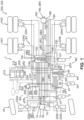
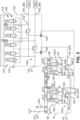
- Fig. 1 illustrates a vehicle 200, namely in particular a commercial vehicle 202, with a first axle, which here is a front axle VA, a second axle, which here is a first rear axle HA1, and a third axle, which here is a second rear axle HA2.
- the vehicle 200 comprises an electronically controllable pneumatic braking system 1, which comprises a primary level B1 and a secondary level B2. It also comprises a manual level B3, as described below.
- the electronically controllable pneumatic braking system 1 comprises an electronic operating control unit 10, which controls the electronically controllable pneumatic braking system 1 at primary level B1.
- the electronic operating control unit 10 is connected to a unit for autonomous driving 210 via a vehicle bus 212 and receives braking request signals SA from the unit. Furthermore, the electronic operating control unit 10 is connected to a first voltage source 204 via a first supply line 203 and is supplied with electrical voltage from the latter.
- the electronic operating control unit 10 converts the braking request signals SA and, based thereon, outputs first service braking signals SB1 to a first brake pressure modulator 12.
- the first brake pressure modulator 12 is provided here for the front axle VA and can thus also be referred to as a front axle modulator.
- the first brake pressure modulator 12 is connected to a first compressed air supply 2 and receives supply pressure from the same. Specifically, the supply pressure pV is provided at a first supply connection 22 of the first brake pressure modulator 12.
- the first brake pressure modulator 12 controls, based on the received first service brake signals SB1, a first service brake pressure pB1 at a first service brake pressure connection 14 and in the Fig. 1 shown embodiment also at a first further service brake pressure connection 15, wherein the first service brake pressure connection 14 and the first additional service brake pressure connection 15 only in Fig. 1 are shown separately and are actually connected inside the first brake pressure modulator 12.
- the first service brake pressure pB1 is determined in the Fig.
- the brake pressure is controlled in an axle-correct manner, so that the same first service brake pressure pB1 is provided on the left and right sides of the vehicle 200. This is initially routed via first and second front axle ABS valves 220a, 220b and then provided to first and second front axle brake actuators 222a, 222b.
- the electronically controllable pneumatic braking system 1 comprises a second brake pressure modulator 100 in the primary level B1, which is provided here for the first and second rear axles HA1, HA2 and can thus also be referred to as a rear axle modulator.
- the second brake pressure modulator 100 is installed with the electronic operating control unit 10 to form a module, which is referred to here as the central module 102.
- the second brake pressure modulator 100 and the electronic operating control unit 10 can also be structurally separate and then connected to one another, for example, via a signal line.
- the electronic operating control unit 10 outputs second and third service brake signals SB2, SB3 to the second brake pressure modulator 100 in accordance with the brake request signals SA that the electronic operating control unit 10 has received from the autonomous driving unit 210.
- the second brake pressure modulator 100 is connected to a second compressed air supply 4 and receives supply pressure pV therefrom.
- the second brake pressure modulator 100 controls a second and a third service brake pressure pB2, pB3 in a side-by-side manner.
- the second service brake pressure pB2 is provided to a first and a third rear axle brake actuator 224a, 224c
- the third service brake pressure pB3 is provided to a second and a fourth rear axle brake actuator 224b, 224d.
- the electronically controllable pneumatic braking system 1 initially comprises an electronic redundancy control unit 50, which is intended to control the electronically controllable pneumatic braking system 1 in the event that the primary level B1 has one or more errors, for example, a power failure in the first voltage source 204, an electronic error in the electronic operating control unit 10, or the like.
- the electronic redundancy control unit 50 is also connected to the autonomous driving unit 210 via the vehicle bus 212 and also receives operating request signals SA from it. However, unlike the electronic operating control unit 10, the electronic redundancy control unit 50 is connected to a second voltage source 206 via a second supply line 205 and is supplied with electrical voltage by the latter.
- the first and second voltage sources 204, 206 are independent of one another, so that a failure in the first voltage source 204 does not lead to a loss of the second voltage source 206, and vice versa.
- the electronic operation control unit 10 and the electronic redundancy control unit 50 are therefore electrically independent of each other.
- the electronic operating control unit 10 and the electronic redundancy control unit 50 are connected via a redundancy bus 230.
- the electronic redundancy control unit 50 can determine the availability of the electronic operating control unit 10 and only take over control of the electronically controllable pneumatic braking system 1 when the electronic operating control unit 10 is not available or is no longer available correctly.
- a first redundancy pressure modulator 52 is provided in the secondary level B2, which is connected to the electronic redundancy control unit 50 and receives first redundancy brake signals SR1 therefrom.
- the first redundancy pressure modulator 52 is connected to a first additional compressed air supply 2A and receives supply pressure therefrom.
- the first redundancy pressure modulator 52 can also be connected to the first compressed air supply 2
- additional redundancy is created by the fact that the first redundancy pressure modulator 52 is connected to the first additional compressed air supply 2A, which is preferably independent of the first compressed air supply 2.
- the first redundancy pressure modulator 52 controls a first redundancy brake pressure pR1 at at least one first redundancy brake pressure connection 54 as a function of the first redundancy brake signals SR1.
- the first redundancy brake pressure pR1 is used to redundantly control the brake actuators controlled by the first brake pressure modulator 12 during operation, in the specific case Fig. 1 In the case shown, the first and second front axle brake actuators 222a, 222b are to be redundantly supplied with compressed air.
- the first redundancy brake pressure connection 54 is connected to a vent connection 16 of the first brake pressure modulator 12 in order to thereby direct the first redundancy brake pressure pR1 through the first brake pressure modulator 12 and to output it to the first and second front axle brake actuators 222a, 222b, optionally with the interposition of the first and second front axle ABS valves 220a, 220b provided here.
- the vent connection 16 and the first vent path 17 connected to it (cf. Fig. 2 ) is also available in the event of a fault on the primary level B1 of the electronically controllable pneumatic brake system 1 and is typically open due to the monostability of the valves.
- the venting of the service brake pressure pB1 can, in the operating case when the control of the electronically controllable pneumatic brake system is carried out by the electronic operating control unit 10, in one case be carried out via the first redundancy pressure modulator 52. For this purpose, this can be a vent (in Fig. 1 not shown). Furthermore, the venting of the first service brake pressure pB1 can also take place via the first brake pressure modulator 12, as will be described below.
- the electronically controllable pneumatic braking system 1 comprises the secondary level B2 also has a second redundancy pressure modulator 60, which is intended to replace the second brake pressure modulator 100.
- the second redundancy pressure modulator 60 is integrated with the electronic redundancy control unit 50 in a redundancy module 51, similar to what was described above with reference to the central module 102.
- the electronic redundancy control unit 50 thus provides second and third redundancy brake signals SR2, SR3 to the second redundancy pressure modulator 60.
- the second redundancy pressure modulator 60 is connected to a second additional compressed air supply 4A, but can also be connected to the second compressed air supply 4. By connecting the second redundancy pressure modulator 60 to the second additional compressed air supply 4A, additional redundancy can be created in the compressed air supplies.
- the second additional compressed air supply 4A is preferably independent of the second compressed air supply 4. It can also be provided that the second additional compressed air supply 4A and the first additional compressed air supply 2A are a common compressed air supply and can therefore be referred to jointly as an additional compressed air supply. It would also be conceivable to introduce cross-redundancy by supplying the second redundancy pressure modulator 60 from the second compressed air supply 2, while the first redundancy pressure modulator 52 is supplied from the second compressed air supply 4.
- the second redundancy pressure modulator controls a second redundancy brake pressure pR2 at a second redundancy brake pressure connection 62 for the right side of the vehicle and thus for the first and third rear axle brake actuators 224a, 224c, and a third redundancy brake pressure pR3 at a third redundancy brake pressure connection 164 for the left side of the vehicle, specifically for the second and fourth rear axle brake actuators 224b, 224d.
- the second redundancy brake pressure connection 62 is connected to a second vent connection 106 of the second brake pressure modulator 100
- the third redundancy brake pressure connection 64 is connected to a third vent connection 108 of the second brake pressure modulator 100, as described with reference to FIG. Fig. 4 and 5 will be explained further.
- the electronically controllable pneumatic brake system 1 according to the embodiment shown here ( Fig. 1 ) a trailer control valve 180 in order to supply any trailer of the vehicle 200 with compressed air and to be able to brake it.
- the trailer control valve 180 has a trailer brake pressure connection 182 for providing a trailer brake pressure pBA and a trailer supply connection 183 for receiving supply pressure pV, here from the first compressed air supply 2.
- the trailer control valve 180 also has a further trailer supply connection 184, which is connected to the second compressed air supply 4 and also receives supply pressure pV.
- the electronically controllable pneumatic braking system 1 shown is intended for the North American region, where it is typical for the trailer control valve 180 to be supplied by two different compressed air supplies. This may be different in European-designed variants.
- the trailer control valve 180 also has a trailer vent port 186 for venting the trailer brake pressure pBA.
- the first redundancy pressure modulator 52 is connected to the trailer vent port 186, specifically via a trailer redundancy brake pressure port 56, at which a trailer redundancy pressure pRA is controlled, which in the exemplary embodiment shown here ( Fig. 1 ) preferably corresponds to the first redundancy brake pressure pR1. In this way, the trailer can also be braked redundantly using a vent path of the trailer control valve 180.
- the electronically controllable pneumatic brake system 1 in the embodiment shown here has a brake value transmitter 300, which is designed as a foot brake valve.
- the brake value transmitter 300 is connected to the electronic operating control unit 10 via a first brake value transmitter line 302 and to the electronic redundancy control unit 50 via a second brake value transmitter line 304.
- the brake value transmitter 300 provides foot brake signals SSB to the electronic operating control unit 10 and the electronic redundancy control unit 50 via these two lines, which also generate the first, second and third Service brake signals SB1, SB2, SB3 as well as the first, second, and third redundant brake signals SR1, SR2, SR3 can be controlled.
- the brake value transmitter 300 comprises a brake value transmitter brake pressure connection 306, at which a brake value transmitter brake pressure pFB can be controlled.
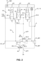
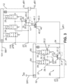
- the Fig. 2 and 3 first illustrate the first brake pressure modulator 12 and the first redundant pressure modulator 52 and their interaction.
- the first brake pressure modulator 12 comprises a pilot control unit 18 and a main valve unit 19, which here has a first operating relay valve 20.
- the first pilot control unit 18 serves to control a first pilot pressure pS1 at the main valve unit 19.
- the first brake pressure modulator 12 is basically designed like known brake pressure modulators and comprises a supply connection 22, which is connected to the first compressed air supply 2 and receives supply pressure pV from it (cf. Fig. 1 ). It also includes a first service brake pressure connection 14, at which the first service brake pressure pB1 is controlled.
- a first additional service brake pressure connection 15 is also provided, which is fluidly connected to the first service brake pressure connection 14.
- the first pilot control unit 18 comprises a first inlet valve 24, a first outlet valve 25 and a first redundancy valve 26.
- the first inlet valve 24 is designed here as a monostable 2/2-way solenoid valve and is spring-loaded into the closed position in Fig. 2 shown switching position.
- the first inlet valve 24 has a first inlet valve connection 24.1, which is connected to the first supply connection 22 and receives supply pressure pV therefrom.
- the first inlet valve 24 has a second inlet valve connection 24.2, which is connected to the first operating relay valve control connection 20.3 and can control the first pilot pressure pS1 thereon.
- the first inlet valve 24 is switched based on a first switching signal S1, which can be provided directly by the electronic operating control unit 10, without a separate electronic control unit of the first brake pressure modulator 12. In the event that the first brake pressure modulator 12 has its own electronic control unit, this provides the first switching signal S1 based on the received first service brake signal SB1 in order to switch the first inlet valve 24 to the Fig. 2 not shown switching position and thus to control the first control pressure pS1.
- the first outlet valve 25 is also designed as a monostable 2/2-way solenoid valve and is stable in the closed Fig. 2 shown switching position.
- the first outlet valve 25 has a first outlet valve connection 25.1, which is also connected to the first operating relay valve control connection 20.3.
- a second outlet valve connection 25.2 is connected to a vent 3.
- the first outlet valve 25 can be switched to the open position by a second switching signal S2. Fig. 2 not shown switching position in order to vent the first pilot pressure pS1.
- the first redundancy valve 26 comprises a first redundancy valve connection 26.1 and a second redundancy valve connection 26.2. It is also designed as a monostable 2/2-way solenoid valve, but in an open in Fig. 2 shown switching position preloaded and energized in a closed in Fig. 2 not shown switching position.
- the first redundancy valve 26 can be switched into the closed position by a third switching signal S3 Fig. 2 not shown.
- the first redundancy valve connection 26.1 is connected to a first foot brake pressure connection 316, at which the brake signal sensor brake pressure pFB can be controlled. If the vehicle 200 is in autonomous operation and the autonomous driving unit 210 takes over control, the first redundancy valve 26 should be closed. Only when the first redundancy valve 26 is moved to the open switching position can the brake signal sensor brake pressure pFB be controlled by the first redundancy valve 26 and controlled at the first operating relay valve control connection 20.3. In this way, the manual fallback level B3 can be implemented. and manual control of the vehicle 200 can be assumed.
- the first operating relay valve 20 comprises a first operating relay valve supply port 20.1, which is connected to the supply port 22 and receives supply pressure therefrom. It further comprises a first operating relay valve working port 20.2, which is connected to the first service brake pressure port 14 and, if applicable, the first further service brake pressure port 15. Depending on the first control pressure pS1 received at the first operating relay valve control port 20.3, the first operating relay valve 20 controls the first service brake pressure pB1, which then preferably corresponds to a volume-amplified control pressure pS1. To vent the first operating relay valve and in particular to vent the first service brake pressure pB1, the first operating relay valve 20 comprises a first operating relay valve vent port 20.4, which also forms the first vent port 16 of the first brake pressure modulator 12.
- a first quick vent valve 40 is provided in the first venting path 17 and serves to vent the first service brake pressure pB1.
- the first quick vent valve 40 has a first quick vent valve connection 40.1, which is connected to the venting path 17 and, in the case shown here, specifically to the first service relay valve vent connection 20.4.
- a second quick vent valve connection 40.2 is connected to the environment or a vent 3
- a third quick vent valve connection 40.3 is connected to the first redundancy brake pressure connection 54 of the first redundancy pressure modulator 52 (cf. Fig. 1 and 3 ).
- the first service brake pressure pB1 can be quickly vented via the quick vent valve 40 and the second quick vent valve connection 40.2, and on the other hand, the first redundancy pressure pR1 can be vented via the first quick vent valve 40, more precisely via the third quick vent valve connection 40.3, the first quick vent valve connection 40.1 and the first service relay valve vent connection 20.4 and in this way also controlled at the first service brake pressure connection 14 and preferably the first further service brake pressure connection 15.
- the first quick vent valve 40 is also integrated into the first brake pressure modulator housing 13, but it can also be connected outside the first brake pressure modulator housing. This is preferred, for example, if the first vent connection 16 is provided outside the first brake pressure modulator housing 13 and not inside it. In this case, the first vent connection 16 arranged on the housing could then be connected to the externally provided first quick vent valve 40.
- the first redundancy pressure modulator 52 comprises a first redundancy pilot control unit 27 and a first redundancy main valve unit 28.
- the first redundancy pilot control unit 27 comprises a first redundancy inlet valve 29 and a first redundancy outlet valve 30.
- the first redundancy main valve unit 28 comprises a first redundancy relay valve 31.
- the first redundancy pressure modulator 52 is constructed in the same way as the first brake pressure modulator 12, except that the first redundancy pressure modulator 52 does not comprise the first redundancy valve 26, since this does not have to implement pneumatic redundancy.
- the first redundancy inlet valve 29 is designed as a monostable 2/2-way solenoid valve and is de-energized into the closed Fig. 3 shown switching position. It has a first redundancy inlet valve connection 29.1, which is connected to a first redundancy supply connection 53, which in turn is connected to the further first compressed air supply 2A and receives supply pressure pV from this.
- a second redundancy inlet valve connection 29.2 is connected to the first redundancy main valve unit 28 and controls a first redundancy pilot pressure pSR1 thereon.
- the first redundancy outlet valve 30 serves to vent the first redundancy pilot pressure pSR1 and is, for this purpose, again designed as a monostable 2/2-way solenoid valve, which, however, is de-energized and pre-tensioned in the open switching position (cf. Fig. 3 ). This is advantageous in order to vent the first redundancy pilot pressure pSR1 in the normal case and thus also keep the first redundancy relay valve 31 in a vented position.
- the first redundancy outlet valve 30 comprises a first redundancy outlet valve connection 30.1 connected to the first redundancy relay valve 31 and a second redundancy outlet valve connection 30.2 connected to one or the vent 3.
- the fourth and fifth switching signals for switching the first redundancy inlet valve 29 and the first redundancy outlet valve 30 can in turn be provided directly by the electronic redundancy control unit 50, or the first redundancy pressure modulator 52 comprises its own control unit which converts the first redundancy brake signal SR1 and, based thereon, controls the fourth and fifth switching signals S4, S5.
- the first redundancy relay valve 31 comprises a first redundancy relay valve supply port 31.1, which is connected to the first redundancy supply port 53 and receives supply pressure pV therefrom.
- a first redundancy relay valve working port 31.2 is connected to the first redundancy brake pressure port 54 in order to control the first redundancy brake pressure pR1 thereat.
- the first redundancy relay valve 31 further has a first redundancy relay valve control port 31.3, which is connected to the first redundancy pilot control unit 27 and receives the first redundancy pilot control pressure pSR1 therefrom.
- the first redundancy relay valve 31 volume-amplifies this pressure and controls it as the first redundancy brake pressure pR1.
- the first redundancy relay valve 31 has a first redundancy relay valve vent port 31.4, which is connected to or forms a first redundancy vent port 55.
- the first redundancy brake pressure pR1 can be vented via this.
- the first redundancy brake pressure port 54 is connected, for example, directly to the first vent port 16, more precisely to the first service relay valve vent port 20.4, the first service brake pressure pB1 can be vented via the first redundancy vent connection 55.
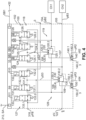
- Fig. 4 and 5 now show in a similar way to the Fig. 2 and 3 the structure of the second brake pressure modulator 100 and the interaction of the second brake pressure modulator 100 with the second redundancy pressure modulator 60.
- the second brake pressure modulator 100 is integrated with the electronic operating control unit 10 to form a central module 102.
- the electronic operating control unit 10 receives brake request signals SA via the vehicle bus 212 and also outputs the first service brake signal SB1 to the first redundancy pressure modulator 52.
- the second brake pressure modulator 100 is designed as a two-channel modulator and has a second service brake pressure connection 104 and a third service brake pressure connection 105, which are independent of one another.
- a second pilot control unit 118 and a second main valve unit 119 are provided for the first channel, namely the second service brake pressure connection 104. Both the second pilot control unit 118 and the second main valve unit 119 are formed identically to the first main valve unit 19, so that reference is generally made to the above description.
- the second pilot control unit 118 comprises a second inlet valve 124 with a third inlet valve connection 124.1, which is connected to the second supply connection 122 and receives supply pressure pV from it.
- a fourth inlet valve connection 124.2 controls a second pilot pressure pS2, which is provided to the second service relay valve 120.
- the second outlet valve 125 includes a third outlet valve port 125.1 connected to the second operating relay valve 120, and a fourth outlet valve port 125.2 connected to one or the vent 3.
- the second outlet valve 125 is switched based on a sixth switching signal provided by the electronic operating control unit 10, while the second outlet valve 125 is switched by a seventh switching signal S7. which is also provided by the electronic operating control unit 10.
- a second redundancy valve 126 has a third redundancy valve connection 126.1, which is connected to a second foot brake pressure connection 318 and receives the brake value sensor brake pressure pFB via this.
- the second redundancy valve can then control the brake value sensor brake pressure at the fourth redundancy valve connection 126.2 and provide it to the second operating relay valve 120 if it is in the open position.
- Fig. 4 shown switching position.
- pneumatic redundancy can be implemented here.
- the second operating relay valve 120 comprises a second operating relay valve supply connection 120.1, which is connected to the second supply connection 122 and receives supply pressure pV, a second operating relay valve working connection 120.2, which is connected to the second service brake pressure connection 104, a second operating relay valve control connection 120.3, which receives the second pilot pressure pS2 and is connected to the second pilot control unit 118, and a second operating relay valve vent connection 120.4.
- the second operating relay valve vent connection 120.4 forms the second vent connection of the second brake pressure modulator 100. This opens into a second vent path 107, in which, as also with reference to Fig. 2 and 3 described, a second quick exhaust valve 140 is provided.
- the second quick exhaust valve 140 has a fourth quick exhaust valve connection 140.1, which is connected to the second exhaust connection 106 or, more precisely, to the second operating relay valve exhaust connection 120.4.
- a fifth quick exhaust valve connection 140.2 is connected to a vent or the environment, and a sixth quick exhaust valve connection 140.3 is connected to the second redundancy brake pressure connection 62 and can receive the second redundancy brake pressure pR2 from it (cf. Fig. 1 ).
- the second redundancy brake pressure pR2 can be fed to the second exhaust path 107 and thus to the second operating relay valve exhaust connection 120.4 in order to control the second redundancy brake pressure pR2 at the second service brake pressure connection 104 in the event of a fault in the electronic operating control unit 10, which ensures that, for example, the sixth and seventh switching signals can no longer be provided correctly and thus the second pilot control pressure pS2 can no longer be controlled correctly, in order to be able to make this available to the first and third rear axle brake actuators 224a, 224c.
- an identical valve arrangement is provided with a third pilot control unit 127 and a third main valve unit 128, which includes a third service relay valve 130.
- the third pilot control unit has a third inlet valve 131 and a third outlet valve 132. Furthermore, it has a third redundancy valve 133.
- the third inlet valve 131 is again designed as a monostable 2/2-way solenoid valve and is de-energized in the closed position. Fig. 4 shown switching position. It comprises a fifth inlet valve connection 131.1, which is connected to the second supply connection 122 and receives supply pressure pV.
- a sixth inlet valve connection 131.2 is connected to the third main valve unit 128 and controls a third pilot pressure pS3 thereon.
- the third outlet valve 132 is connected to the third main valve unit 128 via a fifth outlet valve connection 132.1 and can thus vent the third pilot pressure pS3.
- a sixth outlet valve connection 132.2 of the third outlet valve 132 is connected to one or the vent 3.
- the third inlet valve 131 can be switched by a ninth switching signal S9 and the third outlet valve 132 by a tenth switching signal S10.
- the third redundancy valve 133 comprises a fifth redundancy valve connection 133.1, which is connected to the second foot brake pressure connection 318 and thus receives the brake signal transmitter brake pressure pFB.
- the third redundancy valve 133 is de-energized in the open position.
- Fig. 4 shown switching position and can then control the brake value transmitter brake pressure pFB at a sixth redundancy valve connection 133.2 and provide this as the third pilot pressure pS3.
- the third operating relay valve 130 has a third operating relay valve supply port 130.1, which is connected to the second supply port 122, a third operating relay valve working port 130.2, which is connected to the third service brake pressure port 105, a third operating relay valve control port 130.3, at which the third pilot pressure pS3 is controlled, and a third operating relay valve vent port 130.4, which here also forms the third vent port 108 of the second brake pressure modulator 100 and opens into a third vent path 109.
- a third quick vent valve 150 is provided in the third vent path 109.
- the third quick vent valve 150 is configured identically to the second quick vent valve 140 and has a seventh quick vent valve port 150.1 connected to the third vent port, more precisely to the third service relay valve vent port 130.4.
- An eighth quick vent valve port 150.2 is connected to one or the vent 3, and a ninth quick vent valve port 150.3 is connected to the third redundancy brake pressure port 64 of the second redundancy pressure modulator 60 and receives the third redundancy brake pressure therefrom.
- the third redundancy brake pressure can also be controlled through the third vent path 109 and provided at the third service brake pressure port 105.
- the second redundancy pressure modulator 60 is also constructed with two channels to correspond to the second brake pressure modulator 100. It is as described with reference to Fig. 1 described with the electronic redundancy control unit 50 in a redundancy module 51 and comprises, for the second redundancy brake pressure connection 62, a valve unit with a second redundancy pilot control unit 151 and a second redundancy main valve unit 152.
- the second redundancy pilot control unit 151 has a second redundancy inlet valve 153, which has a third redundancy inlet valve connection 153.1, which is connected to a second redundancy supply connection 67 and receives supply pressure pV from this.
- the second redundancy supply connection 67 is connected to the second compressed air supply 4 or the second another compressed air supply 4A.
- a fourth redundancy inlet valve connection 153.2 is connected to the second redundancy main valve unit 152 and controls a second redundancy pilot pressure pSR2 to it.
- the second redundancy outlet valve 154 is connected to a third redundancy outlet valve connection 154.1 to the second redundancy main valve unit 152 and can thus vent the second redundancy pilot pressure pSR2.
- the fourth redundancy outlet valve connection 154.2 is connected to one or the vent 3.
- the second redundancy outlet valve is in turn designed as a monostable 2/2-way solenoid valve and is de-energized in the open in Fig. 5 shown switching position. While the second redundancy inlet valve 153 can be switched by a twelfth switching signal S12, the second redundancy outlet valve 154 can be switched by a thirteenth switching valve S13.
- the second redundancy main valve unit 152 comprises a second redundancy relay valve 155 with a second redundancy relay valve supply connection 155.1, which is connected to the second redundancy supply connection 67 and receives supply pressure pV, a second redundancy relay valve working connection 155.2, which is connected to the second redundancy brake pressure connection 62 in order to control the second redundancy brake pressure pR2 thereat, a second redundancy relay valve control connection 155.3, which is connected to the second redundancy pilot control unit 151 and receives the second redundancy pilot control pressure pSR2 and a second redundancy relay valve vent connection 155.4, which is connected to one or the vent 3 and serves to vent the second redundancy brake pressure pR2.
- the second redundancy brake pressure connection 62 is directly connected to the second service relay valve vent connection 120.4, the second service brake pressure pB2 can also be vented via the second redundancy relay valve vent connection 155.4.
- the second redundancy pressure modulator for the second channel comprises a valve arrangement which is identical to the valve arrangement for the first channel of the second redundancy pressure modulator 60. Specifically, it has a third redundancy pilot control unit 156 and a third redundancy main valve unit 157.
- the third redundancy pilot control unit 156 serves to provide a third redundancy control pressure pSR3 to the third redundancy main valve unit 157.
- the third redundancy pilot control unit 156 comprises a third redundancy inlet valve 158 with a fifth redundancy inlet valve connection 158.1, which is connected to the second redundancy supply connection 67 and receives supply pressure pV therefrom.
- a sixth redundancy inlet valve connection 158.2 is then connected to the third redundancy main valve unit 157 and controls the third redundancy control pressure pSR3 thereat.
- the third redundancy pilot control unit 156 comprises a third redundancy outlet valve 159 with a fifth redundancy outlet valve connection 159.1, which is connected to the third redundancy main valve unit 157, and a sixth redundancy outlet valve connection 159.2, which is connected to one or the vent 3.
- the third redundancy main valve unit 157 comprises a third redundancy relay valve 160 with a third redundancy relay valve supply connection 160.1, which is connected to the second redundancy supply connection 67 and receives supply pressure.
- a third redundancy relay valve working connection 160.2 is connected to the third redundancy brake pressure connection 64 and controls the third redundancy brake pressure pR3 thereat.
- a third redundancy relay valve control port 160.3 is connected to the third redundancy pilot control unit 156 and receives the third redundancy pilot pressure pSR3 therefrom.
- a third redundancy relay valve vent port 160.4 is connected to one or the vent 3.
- the third service brake pressure pB3 can also be vented via the third redundancy relay valve 160.
- the third redundancy inlet valve 158 can be switched by a fourteenth switching signal S14 and the third redundancy outlet valve 159 can be switched by a fifteenth switching signal S15.
Landscapes
- Engineering & Computer Science (AREA)
- Transportation (AREA)
- Mechanical Engineering (AREA)
- Braking Systems And Boosters (AREA)
- Valves And Accessory Devices For Braking Systems (AREA)
Description
- Die Erfindung betrifft ein elektronisch steuerbares pneumatisches Bremssystem für ein Fahrzeug, vorzugsweise Nutzfahrzeug, mit einer elektronischen Betriebssteuereinheit und wenigstens einem ersten Bremsdruckmodulator, der mit einem ersten Druckluftvorrat zum Empfangen von Vorratsdruck verbunden ist, und der in Abhängigkeit von ersten Betriebsbremssignalen, die von der elektronischen Betriebssteuereinheit bereitgestellt werden, einen ersten Betriebsbremsdruck an wenigsten einem ersten Betriebsbremsdruckanschluss aussteuert. Der erste Bremsdruckmodulator weist einen ersten Entlüftungsanschluss auf zum Entlüften des ersten Betriebsbremsdrucks. Das Bremssystem weist ferner eine elektronische Redundanzsteuereinheit und wenigstens einen ersten Redundanzdruckmodulator auf, der mit dem ersten Druckluftvorrat oder einem weiteren Druckluftvorrat zum Empfangen von Vorratsdruck verbunden ist, und der in Abhängigkeit von ersten Redundanzbremssignalen, die von der elektronischen Redundanzsteuereinheit bereitgestellt werden, einen ersten Redundanzbremsdruck an wenigsten einem ersten Redundanzbremsdruckanschluss aussteuert. Der erste Redundanzdruckmodulator weist einen ersten Redundanz-Entlüftungsanschluss auf zum Entlüften des ersten Redundanzbremsdrucks.
- Konzepte zur redundanten Aussteuerung eines Bremsdrucks nutzen dabei in der Regel teilweise redundante Komponenten und teilweise vorhandene Komponenten, um den Bremsdruck auszusteuern. So ist beispielsweise aus
DE 10 2016 005 318 A1 ein System bekannt, bei dem, für den Fall, dass eine zentrale Steuereinheit ausfällt, die anderenfalls einen Vorderachsmodulator elektronisch ansteuern würde, ein Bypassventil pneumatisch einen Redundanzdruck aussteuert, der dann dem Vorderachsmodulator bereitgestellt wird, um auf diese Weise eine redundante pneumatische Aussteuerung des Vorderachsbremsdrucks zu erreichen. Allgemein offenbartDE 10 2016 005 318 A1 ein elektronisch steuerbares pneumatisches Bremssystem mit mindestens zwei Bremskreisen, wobei mindestens einem der mindestens zwei Bremskreise ein elektrisch und pneumatisch steuerbares Steuerventil und einem weiteren der mindestens zwei Bremskreise ein elektrisch steuerbares Parkbremsventil zugeordnet ist, zum Vorgeben von Bremsdrücken zur Ansteuerung von Radbremsen des jeweiligen Bremskreises. Eine erste Steuereinheit ist vorgesehen, die ausgebildet ist, das jeweilige Steuerventil in Abhängigkeit von einer automatisiert angeforderten Fahrzeug-Soll-Verzögerung oder einer vom Fahrer vorgegebenen Betätigung über ein Bremspedal elektrisch auszusteuern. Ferner ist eine zweite Steuereinheit vorgesehen, die dazu ausgebildet ist, das Parkbremsventil in Abhängigkeit von der automatisiert angeforderten Fahrzeug-Soll-Verzögerung elektrisch zu steuern, wenn eine elektrische Ansteuerung des jeweiligen Steuerventils verhindert ist zum Ausbilden einer elektronisch pneumatisch gesteuerten Redundanz. Weiterhin ist ein einem der Steuerventile zugeordnetes Bypassventil vorgesehen, das ausgebildet ist, das zugeordnete Steuerventil pneumatisch anzusteuern, wobei die pneumatische Ansteuerung in Abhängigkeit von der automatisiert angeforderten Fahrzeug-Soll-Verzögerung oder in Abhängigkeit von der von dem Fahrer vorgenommenen Betätigung des Bremspedals erfolgt, wenn eine elektrische Ansteuerung des jeweiligen Steuerventils verhindert ist. - Eine solche Gestaltung erfordert allerdings, dass der entsprechende Redundanzanschluss des Steuerventils, nämlich des Vorderachsmodulators oder Hinterachsmodulators, funktionsfähig ist. Dadurch ist eine solche Lösung abhängig davon, dass eine Hauptaktuatorik des Steuerventils, nämlich Vorderachsmodulator oder Hinterachsmodulator, funktionsfähig ist.
- Daneben gibt es andere Ansätze, die ein vollständig redundantes Bremssystem aufbauen, wie insbesondere in
DE 10 2019 106 591 A1 offenbart. Gemäß der dortigen Lehre sind alle relevanten Systemelemente aufgedoppelt und so ein vollständig redundantes Bremssystem aufgebaut. Die Bremssysteme werden dann über Select-High-Ventile an den Bremsaktuatoren zusammengeführt. Bei dieser Lösung besteht aber der strömungstechnische Nachteil, dass auch das Primärsystem den Bremsdruck nur über die Select-High-Ventile an den Bremsaktuatoren aussteuern kann und somit nicht unmittelbar. Zudem ergibt sich durch die vollständige Aufdoppelung der einzelnen Bauelemente auch ein erhöhter Bauraumbedarf. - Aufgabe der vorliegenden Erfindung ist es daher, die im Grunde gut funktionierenden bestehenden Systeme weiter zu verbessern und eine hohe Verfügbarkeit bei gleichzeitig strömungstechnisch vorteilhaften Lösungen, die weniger oder keine Rückwirkung auf das Primärsystem haben.
- Die Erfindung löst die Aufgabe bei einem elektronisch steuerbaren pneumatischen Bremssystem der eingangs genannten Art dadurch, dass der erste Redundanzbremsdruckanschluss des Redundanzdruckmodulators mit dem ersten Entlüftungsanschluss des ersten Bremsdruckmodulators verbunden ist, sodass der erste Redundanzbremsdruck über einen ersten Entlüftungspfad des ersten Bremsdruckmodulators an dem ersten Betriebsbremsdruckanschluss des ersten Bremsdruckmodulators aussteuerbar ist.
- Der Erfindung liegt die Erkenntnis zugrunde, dass der Entlüftungspfad eines Modulators auch bei einem schweren Fehler verfügbar ist. Anders als ein Redundanzanschluss eines Modulators, der auf die Verfügbarkeit einer Hauptaktuatorik des Modulators angewiesen ist, weil beispielsweise ein am Redundanzanschluss ausgesteuerter Steuerdruck zunächst auf eine Steuerfläche eines Relaisventils wirkt, um diesen Steuerdruck volumenzuverstärken, benötigt eine Aussteuerung des Bremsdrucks über den Entlüftungspfad keine solche Aktuatorik und kann auch bei einem fehlerhaften Relaisventil in der Regel verwendet werden. Anders als bei einem Redundanzanschluss üblich wird gemäß der Erfindung vorgesehen, dass der erste Redundanzdruckmodulator einen ersten Redundanzbremsdruck aussteuert, und zwar einen Volumendruck, nicht lediglich einen Steuerdruck, der noch einer Volumenverstärkung bedarf. Der Redundanzbremsdruck wird erfindungsgemäß durch den Entlüftungspfad des ersten Bremsdruckmodulators durchgesteuert und an dem ersten Betriebsbremsdruckanschluss bereitgestellt, vorzugsweise unmoduliert. Weiterhin ist kein Select-High-Ventil erforderlich, um den Redundanzbremsdruck und Betriebsbremsdruck wechselseitig oder bedarfsweise dem Bremsaktuator zuzuführen. Es wird auf diese Weise also eine bauliche Vereinfachung der im Stand der Technik bekannten Lösung erreicht, bei gleichzeitiger Erhöhung der Stabilität und Verfügbarkeit und Optimierung der strömungstechnischen Situation. Der erste Bremsdruckmodulator kann beispielsweise für eine Vorderachse vorgesehen sein und so als Vorderachsmodulator bezeichnet werden. Ebenso kann er für eine Hinterachse vorgesehen sein und als Hinterachsmodulator bezeichnet werden. Der erste Betriebsbremsdruck wäre dann im ersteren Fall ein Vorderachsbetriebsbremsdruck, im letzteren Fall ein Hinterachsbetriebsbremsdruck. Es kann auch vorgesehen sein, dass der erste Bremsdruckmodulator nicht für eine Achse, sondern für eine Fahrzeugseite vorgesehen ist, wie beispielsweise die linke Seite, oder kreuzweise, beispielsweise für ein linkes Vorderrad und ein rechtes Hinterrad. Es soll zudem verstanden werden, dass das elektronisch steuerbare pneumatische Bremssystem zwei oder mehr Bremsdruckmodulatoren und entsprechend zwei oder mehr Redundanzdruckmodulatoren aufweisen kann. Auch kann vorgesehen sein, dass an den ersten Betriebsbremsdruckanschluss ein, zwei oder mehr Betriebsbremsaktuatoren angeschlossen sind, gegebenenfalls unter Zwischenschaltung von einem oder mehreren ABS-Ventilen. Der erste Bremsdruckmodulator kann dazu ausgebildet sein, eine radgerechte Aussteuerung von Bremsdrücken zu ermöglichen und vorzugsweise von schlupfgeregelten Bremsdrücken. Er kann aber auch dazu vorgesehen sein, lediglich eine achsengerechte Aussteuerung des Betriebsbremsdrucks zu ermöglichen, und insofern kann das Vorsehen von zusätzlich und/oder separat vorgesehenen ABS-Ventilen zweckdienlich sein.
- Gemäß einer ersten bevorzugten Ausführungsform weist der erste Bremsdruckmodulator ein erstes Schnellentlüftungsventil an dem ersten Entlüftungsanschluss auf, zum Entlüften des ersten Betriebsbremsdrucks. Das Schnellentlüftungsventil kann in den Bremsdruckmodulator integriert sein oder separat von diesem beispielsweise an ein Gehäuse des ersten Bremsdruckmodulators von außen angeflanscht sein. Auch ist es denkbar, dass das erste Schnellentlüftungsventil als eigenständige Baueinheit verbaut ist. Über das Schnellentlüftungsventil kann der erste Betriebsbremsdruck rasch und unmittelbar entlüftet werden und es ist nicht erforderlich, den ersten Betriebsbremsdruck beispielsweise über eine zentrale Entlüftung eines Relaiskolbens im ersten Bremsdruckmodulator zu entlüften. An das erste Schnellentlüftungsventil kann zudem ein Schalldämpfer angeschlossen sein.
- Bevorzugt weist das erste Schnellentlüftungsventil einen mit dem ersten Entlüftungspfad verbundenen ersten Schnellentlüftungsventilanschluss, einen mit der Umgebung verbundenen zweiten Schnellentlüftungsventilanschluss und einen mit dem ersten Redundanzbremsdruckanschluss verbundenen dritten Schnellentlüftungsventilanschluss auf. Der mit der Umgebung verbundene zweite Schnellentlüftungsventilanschluss kann auch zu einer Zentralentlüftung führen. Auf diese Weise kann über den Entlüftungspfad einerseits der erste Betriebsbremsdruck bedarfsweise entlüftet werden, wenn ein Abbau des Bremsdrucks im Betriebsbremszylinder gewünscht ist, andererseits auch der erste Redundanzbremsdruck eingespeist werden, nämlich über den dritten Schnellentlüftungsventilanschluss, der mit dem ersten Redundanzbremsdruckanschluss verbunden ist. Das Schnellentlüftungsventil ist vorzugsweise so gebildet, dass in einem Betriebszustand des Bremssystems, in dem der erste Redundanzdruckmodulator nicht aktiv ist, der erste Schnellentlüftungsventilanschluss mit dem zweiten Schnellentlüftungsventilanschluss offen verbunden ist. Beispielsweise kann ein gegen den dritten Schnellentlüftungsventilanschluss vorgespanntes Ventilelement vorgesehen sein, um diesen zunächst abzuschließen und einen unversperrten Entlüftungspfad vom ersten zum zweiten Schnellentlüftungsventilanschluss vorzusehen.
- Gemäß einer weiteren bevorzugten Ausführungsform ist vorgesehen, dass der erste Bremsdruckmodulator ein erstes Betriebsrelaisventil aufweist, welches einen mit einem ersten Vorratsanschluss verbundenen ersten Betriebsrelaisventil-Vorratsanschluss, einen mit dem ersten Betriebsbremsdruckanschluss verbundenen ersten Betriebsrelaisventil-Arbeitsanschluss, einen einen ersten Vorsteuerdruck empfangenden ersten Betriebsrelaisventil-Steueranschluss und einen den ersten Entlüftungsanschluss bildenden oder mit diesem verbundenen ersten Betriebsrelaisventil-Entlüftungsanschluss aufweist. Das erste Betriebsrelaisventil dient im üblichen Fall dazu, den empfangenen ersten Vorsteuerdruck volumenzuverstärken und als ersten Betriebsbremsdruck auszusteuern. Wird kein Vorsteuerdruck bereitgestellt und herrscht am ersten Betriebsrelaisventil-Steueranschluss Umgebungsdruck, ist der erste Betriebsrelaisventil-Entlüftungsanschluss mit dem ersten Betriebsrelaisventil-Arbeitsanschluss verbunden. Dieser Pfad kann dann dazu verwendet werden, den ersten Redundanzbremsdruck durchzusteuern und an dem ersten Betriebsbremsdruckanschluss bereitzustellen. Die Funktionsfähigkeit des ersten Betriebsrelaisventils ist dazu nicht zwingend erforderlich. Es reicht aus, wenn der Entlüftungspfad des Betriebsrelaisventils bereitsteht und zur Aussteuerung des ersten Redundanzbremsdrucks verwendet werden kann. Hierdurch kann die Verfügbarkeit des elektronisch steuerbaren pneumatischen Bremssystems erhöht werden, auch für den Fall, dass das erste Betriebsrelaisventil nicht oder nicht richtig funktioniert.
- In einer bevorzugten Weiterbildung ist der erste Betriebsrelaisventil-Entlüftungsanschluss mit dem ersten Schnellentlüftungsventilanschluss verbunden. Das Schnellentlüftungsventil kann unmittelbar in den ersten Bremsdruckmodulator integriert sein, sodass dieses baulich auch mit dem ersten Betriebsrelaisventil integriert sein kann.
- Gemäß einer weiteren bevorzugten Ausführungsform umfasst das elektronisch steuerbare pneumatische Bremssystem einen zweiten Bremsdruckmodulator, der mit einem zweiten Druckluftvorrat verbunden ist zum Empfangen von Vorratsdruck, und der in Abhängigkeit von zweiten Betriebsbremssignalen, die von der elektronischen Betriebssteuereinheit bereitgestellt werden, wenigstens einen zweiten Betriebsbremsdruck an wenigstens einen zweiten Betriebsbremsdruckanschluss aussteuert. Der zweite Bremsdruckmodulator weist vorzugsweise einen zweiten Entlüftungsanschluss auf zum Entlüften des zweiten Betriebsbremsdrucks. Das elektronisch steuerbare pneumatische Bremssystem umfasst ferner bevorzugt einen zweiten Redundanzdruckmodulator, der mit dem zweiten Druckluftvorrat oder einem weiteren Druckluftvorrat verbunden ist zum Empfangen von Vorratsdruck, und der in Abhängigkeit von zweiten Redundanzbremssignalen, die von der elektronischen Redundanzsteuereinheit bereitgestellt werden, einen zweiten Redundanzbremsdruck an wenigstens einem zweiten Redundanzbremsdruckanschluss aussteuert.
- Der zweite Redundanzdruckmodulator weist vorzugsweise einen zweiten Redundanz-Entlüftungsanschluss auf, zum Entlüften des zweiten Redundanzbremsdrucks. Der zweite Redundanzbremsdruckanschluss ist vorzugsweise so mit dem zweiten Entlüftungsanschluss verbunden, dass der zweite Redundanzbremsdruck über einen zweiten Entlüftungspfad des zweiten Bremsdruckmodulators an dem zweiten Betriebsbremsdruckanschluss aussteuerbar ist. Die beschriebene Ausführungsform umfasst demnach eine Verdoppelung der Bremsdruckmodulatoren und Redundanzdruckmodulatoren, um so zwei Achsen, zwei Räder, zwei Seiten oder Ähnliches des Fahrzeugs unabhängig voneinander einbremsen zu können. Für den Fall, dass der erste Bremsdruckmodulator ein Vorderachsmodulator ist, ist der zweite Bremsdruckmodulator vorzugsweise ein Hinterachsmodulator. Der erste und der zweite Bremsdruckmodulator können identisch oder verschieden ausgebildet sein. Beispielsweise kann der erste Bremsdruckmodulator als Einkanalmodulator ausgebildet sein, während der zweite Bremsdruckmodulator als Zweikanalmodulator ausgebildet ist oder umgekehrt. Auch können beide als Einkanalmodulator oder beide als Zweikanalmodulator ausgebildet sein. Das Gleiche gilt auch für den ersten und den zweiten Redundanzdruckmodulator. Der erste Redundanzdruckmodulator kann als Einkanalmodulator und der zweite Redundanzdruckmodulator als Zweikanalmodulator ausgebildet sein oder umgekehrt. Auch können beide Redundanzdruckmodulatoren als Einkanalmodulator oder Zweikanalmodulator ausgebildet sein. Dies gilt unabhängig von der Ausgestaltung des ersten und zweiten Bremsdruckmodulators. Jegliche denkbare Paarung ist hier bevorzugt. Wie auch der erste Redundanzdruckmodulator kann der zweite Redundanzdruckmodulator mit dem zweiten Druckluftvorrat oder einem weiteren Druckluftvorrat verbunden sein. Der weitere Druckluftvorrat ist vorzugsweise unabhängig vom zweiten Druckluftvorrat, um so ein redundantes Bremsen auch bei einem Ausfall des zweiten Druckluftvorrats zu verhindern. Der zweite Druckluftvorrat ist dem Primärsystem zugeordnet, während der weitere Druckluftvorrat der Redundanzebene zugeordnet sein kann. Der weitere Druckluftvorrat, der den zweiten Redundanzdruckmodulator versorgt, kann derselbe weitere Vorrat sein, der auch den ersten Redundanzdruckmodulator versorgt. Auch ist bevorzugt, dass der erste und der zweite Redundanzdruckmodulator über eigene weitere Druckluftvorräte verfügen, um so die Unabhängigkeit vom Primärsystem weiter auszugestalten.
- Vorzugsweise weist der zweite Bremsdruckmodulator ein zweites Schnellentlüftungsventil an dem zweiten Entlüftungsanschluss auf, zum Entlüften des zweiten Betriebsbremsdrucks. Für das zweite Schnellentlüftungsventil gilt das oben Gesagte zum ersten Schnellentlüftungsventil analog. Auch dieses kann in den zweiten Bremsdruckmodulator integriert sein oder an ein Gehäuse des zweiten Bremsdruckmodulators angeflanscht oder als separates Element im Bremssystem verbaut sein.
- Weiter ist bevorzugt, dass das zweite Schnellentlüftungsventil einen mit dem zweiten Entlüftungspfad verbundenen vierten Schnellentlüftungsventilanschluss, einen mit der Umgebung verbundenen fünften Schnellentlüftungsventilanschluss und einen mit dem zweiten Redundanzbremsdruckanschluss verbundenen sechsten Schnellentlüftungsventilanschluss aufweist. Auch hier gilt das oben zum ersten Schnellentlüftungsventil Gesagte, sodass für die Vorteile und Ausführungsformen des zweiten Schnellentlüftungsventils auf die des ersten Schnellentlüftungsventils verwiesen wird.
- In ähnlicher Weise wie der erste Bremsdruckmodulator kann auch der zweite Bremsdruckmodulator ein zweites Betriebsrelaisventil aufweisen, welches einen mit einem zweiten Vorratsanschluss verbundenen zweiten Betriebsrelaisventil-Vorratsanschluss, einen mit dem zweiten Betriebsbremsdruckanschluss verbundenen zweiten Betriebsrelaisventil-Arbeitsanschluss, einen einen zweiten Vorsteuerdruck empfangenden Betriebsrelaisventil-Steueranschluss und einen den zweiten Entlüftungsanschluss bildenden oder mit diesem verbundenen zweiten Betriebsrelaisventil-Entlüftungsanschluss aufweist. Der zweite Betriebsrelaisventil-Entlüftungsanschluss kann mit dem vierten Schnellentlüftungsventilanschluss verbunden sein.
- In einer weiteren Ausgestaltung ist vorgesehen, dass der zweite Bremsdruckmodulator in Abhängigkeit von dritten Betriebsbremssignalen, die von der elektronischen Betriebssteuereinheit bereitgestellt werden, einen dritten Betriebsbremsdruck an wenigstens einem dritten Betriebsbremsdruckanschluss aussteuert, wobei der zweite Bremsdruckmodulator einen dritten Entlüftungsanschluss aufweist zum Entlüften des dritten Betriebsbremsdrucks. Der zweite Redundanzdruckmodulator steuert in Abhängigkeit von dritten Redundanzbremssignalen, die von der elektronischen Redundanzsteuereinheit bereitgestellt werden, einen dritten Redundanzbremsdruck an wenigsten einem dritten Redundanzbremsdruckanschluss aus. Der zweite Redundanz-Entlüftungsanschluss ist wirksam zum Entlüften des dritten Redundanzbremsdrucks und der dritte Redundanzbremsdruckanschluss ist mit dem dritten Entlüftungsanschluss verbunden, sodass der dritte Redundanzbremsdruck über einen dritten Entlüftungspfad des zweiten Bremsdruckmodulators an dem dritten Betriebsbremsdruckanschluss aussteuerbar ist. Nach dieser Ausführungsform sind sowohl der zweite Bremsdruckmodulator als auch der zweite Redundanzdruckmodulator zweikanalig ausgebildet, sodass jeweils die zweiten und dritten Redundanzbremsdruckanschlüsse mit zweiten und dritten Entlüftungsanschlüssen verbunden sind, um über zweite und dritte Entlüftungspfade des zweiten Bremsdruckmodulators den zweiten und dritten Redundanzbremsdruck einzusteuern. Eine solche Gestaltung bietet sich vor allem an, wenn seitengerecht ein Bremsdruck ausgesteuert werden soll unter Verwendung nur eines Modulators.
- Bei einer solchen Ausführungsform umfasst der zweite Bremsdruckmodulator vorzugsweise ein drittes Schnellentlüftungsventil an dem dritten Entlüftungsanschluss zum Entlüften des dritten Betriebsbremsdrucks. Bevorzugt weist das dritte Schnellentlüftungsventil einen mit dem dritten Entlüftungspfad verbundenen siebten Schnellentlüftungsventilanschluss, einen mit der Umgebung verbundenen achten Schnellentlüftungsventilanschluss und einen mit dem dritten Redundanzbremsdruckanschluss verbundenen neunten Schnellentlüftungsventilanschluss auf. Insofern entspricht das dritte Schnellentlüftungsventil in seiner Gestaltung dem ersten und dem zweiten Schnellentlüftungsventil und für die weiteren Vorteile und Weiterbildungen wird auf die obige Beschreibung zum ersten Schnellentlüftungsventil verwiesen. Diese Ausführungen gelten hier analog.
- Ferner kann auch vorgesehen sein, dass der zweite Bremsdruckmodulator ein drittes Betriebsrelaisventil aufweist, welches einen mit dem zweiten Vorratsanschluss verbundenen dritten Betriebsrelais-Vorratsanschluss, einen mit dem dritten Betriebsbremsdruckanschluss verbundenen dritten Betriebsrelaisventil-Arbeitsanschluss, einen einen dritten Vorsteuerdruck empfangenden dritten Betriebsrelaisventil-Steueranschluss und einen den dritten Entlüftungsanschluss bildenden oder mit diesem verbundenen dritten Betriebsrelaisventil-Entlüftungsanschluss aufweist. Das dritte Betriebsrelaisventil ist demnach für den zweiten Kanal des auf diese Weise zweikanalig ausgebildeten zweiten Bremsdruckmodulators vorgesehen. Jeder Kanal des zweikanaligen zweiten Bremsdruckmodulators verfügt über ein eigenes Betriebsrelaisventil mit einem eigenen Entlüftungsanschluss. Bevorzugt ist auch, wie ebenfalls in den vorherigen Ausführungsformen erläutert, dass der dritte Betriebsrelaisventil-Entlüftungsanschluss mit dem siebten Schnellentlüftungsventilanschluss verbunden ist. Auf diese Weise kann dem dritten Betriebsrelaisventil-Entlüftungsanschluss der dritte Redundanzbremsdruck zugeführt werden und der dritte Betriebsrelaisventil-Entlüftungsanschluss kann entlüftet werden.
- In einer weiteren bevorzugten Ausführungsform des elektronisch steuerbaren pneumatischen Bremssystems weist dieses ein Anhängersteuerventil mit wenigstens einem Anhängerbremsdruckanschluss zum Bereitstellen eines Anhängerbremsdrucks für einen Anhänger, einem Anhängervorratsanschluss zum Empfangen von Vorratsdruck und einem Anhängerentlüftungsanschluss zum Entlüften des Anhängerbremsdrucks auf. Das Anhängersteuerventil ist vorzugsweise mit der elektronischen Betriebssteuereinheit verbunden und empfängt von dieser Anhängerbremssignale und steuert vorzugsweise basierend hierauf den Anhängerbremsdruck aus. Über das Anhängersteuerventil kann ein Anhänger, der gegebenenfalls an das Fahrzeug angeschlossen ist, gebremst werden. Das Anhängersteuerventil weist hierzu vorzugsweise ein oder mehrere elektrisch schaltbare Magnetventile auf. Das Anhängersteuerventil kann zudem ein Anhänger-Relaisventil aufweisen, um einen von elektrisch schaltbaren Magnetventilen ausgesteuerten Vorsteuerdruck volumenzuverstärken und dem Anhänger bereitzustellen. Je nach Ausgestaltung des elektronisch steuerbaren pneumatischen Bremssystems für den europäischen oder den nordamerikanischen Raum kann die genaue Gestaltung des Anhängersteuerventils abweichen. Das hierin beschriebene Anhängersteuerventil soll beide Varianten umfassen.
- In einer bevorzugten Weiterbildung weist der erste Redundanzdruckmodulator oder der zweite Redundanzdruckmodulator einen Anhänger-Redundanzbremsdruckanschluss zum Bereitstellen eines Anhängerredundanzdrucks auf. Typischerweise wird ein Anhängersteuerventil redundant über Drücke von einer Vorderachse des Fahrzeugs angesteuert, sodass für den Fall, dass der erste Redundanzdruckmodulator für die Vorderachse des Fahrzeugs vorgesehen ist, es der erste Redundanzdruckmodulator ist, der den Anhänger-Redundanzbremsdruckanschluss zum Bereitstellen des Anhängerredundanzdrucks aufweist. Alternativ kann aber auch der zweite Redundanzdruckmodulator, der in dem beschriebenen Fall dann vorzugsweise für die Hinterachse vorgesehen ist, derjenige sein, der den Anhängerredundanzbremsdruckanschluss zum Bereitstellen des Anhängerredundanzdrucks aufweist. Der Anhängerredundanzdruck kann grundsätzlich an einem Redundanzanschluss des Anhängersteuerventils wie üblich und im Stand der Technik bekannt ausgesteuert werden. Besonders bevorzugt aber ist der Anhänger-Redundanzbremsdruckanschluss mit dem Anhängerentlüftungsanschluss verbunden, sodass der Anhänger-Redundanzdruck über einen Anhänger-Entlüftungspfad des Anhängersteuerventils an dem Anhängerbremsdruckanschluss aussteuerbar ist. Dieselben Überlegungen, die oben in Bezug auf den ersten Bremsdruckmodulator und den zweiten Bremsdruckmodulator angestellt wurden, nämlich dahingehend, dass ein Entlüftungspfad dieser zum Ansteuern des Redundanzbremsdrucks verwendet wird, wird hier nun auf das Anhängersteuerventil angewandt. Auch bei diesem wird der Anhänger-Entlüftungspfad zum Einsteuern des Anhänger-Redundanzdrucks verwendet.
- Der Anhänger-Redundanzdruck kann dem ersten Redundanzdruck, dem zweiten Redundanzdruck und/oder dem dritten Redundanzdruck entsprechen. Auch wenn der erste Redundanzdruckmodulator den Anhänger-Redundanzbremsdruckanschluss aufweist, heißt dies nicht zwingend, dass der erste Redundanzdruckmodulator als Zweikanalmodulator ausgebildet sein kann. Vielmehr kann der erste Redundanzdruckmodulator nach wie vor als Einkanalmodulator ausgebildet sein und der Anhänger-Redundanzbremsdruck entspricht dem ersten Redundanzbremsdruck, sodass der erste Redundanzbremsdruckanschluss und der Anhänger-Redundanzbremsdruckanschluss beispielsweise über eine Y-Leitung mit dem entsprechenden Ventil verbunden sind.
- In einer bevorzugten Weiterbildung ist die elektronische Betriebssteuereinheit mit einer ersten Spannungsquelle verbunden und die elektronische Redundanzsteuereinheit ist mit einer zweiten Spannungsquelle verbunden. Die ersten und zweiten Spannungsquellen sind vorzugsweise unabhängig voneinander, sodass ein Fehler in der einen Spannungsquelle nicht zum Ausfall der anderen Spannungsquelle führen kann. Auf diese Weise kann die Verfügbarkeit des elektronisch steuerbaren pneumatischen Bremssystems weiter erhöht werden.
- Ebenso ist vorzugsweise vorgesehen, dass der erste Druckluftvorrat und der weitere Druckluftvorrat unabhängig voneinander sind. Vorzugsweise werden der erste Druckluftvorrat und der weitere Druckluftvorrat von zwei verschiedenen und unabhängig voneinander vorgesehenen Druckluftquellen, insbesondere zwei Druckluftversorgungen, versorgt. Beispielsweise kann vorgesehen sein, dass sowohl für den ersten Druckluftvorrat als auch für den weiteren Druckluftvorrat eine eigene Luftaufbereitungseinheit vorgesehen ist. Alternativ sind der erste Druckluftvorrat und der weitere Druckluftvorrat mit einer gemeinsamen Druckluftaufbereitung verbunden, aber durch ein Mehrkreisschutzventil pneumatisch getrennt. Dasselbe gilt vorzugsweise für den zweiten Druckluftvorrat und den weiteren Druckluftvorrat. Insgesamt können vier Druckluftvorräte vorgesehen sein, beispielsweise der erste Druckluftvorrat für den ersten Bremsdruckmodulator, der weitere Druckluftvorrat für den ersten Redundanzdruckmodulator, der zweite Druckluftvorrat für den zweiten Bremsdruckmodulator und ein zweiter weiterer Druckluftvorrat für den zweiten Redundanzdruckmodulator. Darüber hinaus kann für jeden weiteren Bremsdruckmodulator ein eigener Druckluftvorrat und für jeden weiteren Redundanzdruckmodulator ein weiterer eigener Druckluftvorrat vorgesehen sein, für die das oben Gesagte gilt. Vorzugsweise sind dabei jeweils die für die Redundanzdruckmodulatoren vorgesehenen Druckluftvorräte unabhängig von den für die Bremsdruckmodulatoren vorgesehenen Druckluftvorräten. Es kann vorgesehen sein, dass die Druckluftvorräte für die Bremsdruckmodulatoren nicht unabhängig voneinander sind und auch die weiteren Druckluftvorräte für die Redundanzdruckmodulatoren nicht unabhängig voneinander sind, aber alle für die Redundanzdruckmodulatoren vorgesehenen weiteren Druckluftvorräte unabhängig von den für die Bremsdruckmodulatoren vorgesehenen Druckluftvorräten sind.
- Gemäß einer weiteren bevorzugten Ausführungsform weist das elektronisch steuerbare pneumatische Bremssystem eine Einheit für autonomes Fahren und einen Fahrzeug-BUS auf, wobei die elektronische Betriebssteuereinheit und die elektronische Redundanzsteuereinheit über den Fahrzeug-BUS oder eine alternative Netzwerkkommunikation mit der Einheit für autonomes Fahren verbunden sind und von dieser Bremsanforderungssignale empfangen. Die elektronische Betriebssteuereinheit und die elektronische Redundanzsteuereinheit sind dann vorzugsweise in der Lage, die elektronischen Bremsanforderungssignale umzusetzen und den oder die Bremsdruckmodulatoren und den oder die Redundanzdruckmodulatoren entsprechend anzusteuern. Alternative Netzwerckommunikationen können beispielsweise eine direkte Verkabelung, ein CAN-BUS oder andere Systeme umfassen. Auch eine drahtlose Kommunikation kann grundsätzlich in Betracht kommen.
- In einem weiteren Aspekt löst die Erfindung die eingangs genannte Aufgabe durch ein Fahrzeug, vorzugsweise Nutzfahrzeug, mit einer Vorderachse, wenigstens einer Hinterachse und einem elektronisch steuerbaren pneumatischen Bremssystem gemäß einer der vorstehend beschriebenen bevorzugten Ausführungsformen eines elektronisch steuerbaren pneumatischen Bremssystems gemäß dem ersten Aspekt der Erfindung. Es soll verstanden werden, dass das elektronisch steuerbare pneumatische Bremssystem gemäß dem ersten Aspekt der Erfindung und das Fahrzeug gemäß dem zweiten Aspekt der Erfindung gleiche und ähnliche Unteraspekte aufweisen, wie sie insbesondere in den abhängigen Ansprüchen niedergelegt sind. Insofern wird vollumfänglich auf die obige Beschreibung Bezug genommen.
- Vorzugsweise ist der erste Bremsdruckmodulator der Vorderachse des Fahrzeugs und der zweite Bremsdruckmodular der wenigstens einen Hinterachse des Fahrzeugs zugeordnet. Der zweite Bremsdruckmodulator kann auch der ersten und der zweiten Hinterachse des Fahrzeugs zugeordnet sein. Der erste Bremsdruckmodulator ist vorzugsweise als Einkanalmodulator ausgebildet und der zweite Bremsdruckmodulator vorzugsweise als Zweikanalmodulator, der eine seitengerechte Aussteuerung von Bremsdrücken erlaubt.
- Ausführungsformen der Erfindung werden nun nachfolgend anhand der Zeichnungen beschrieben. Diese sollen die Ausführungsformen nicht notwendigerweise maßstäblich darstellen, vielmehr sind die Zeichnungen, wenn dies zur Erläuterung dienlich ist, in schematisierter und/oder leicht verzerrter Form ausgeführt. Im Hinblick auf Ergänzungen der aus den Zeichnungen unmittelbar erkennbaren Lehren wird auf den einschlägigen Stand der Technik verwiesen.
- Der Einfachheit halber sind nachfolgend für identische oder ähnliche Teile oder Teile mit identischer oder ähnlicher Funktion gleiche Bezugszeichen verwendet.
- Weitere Vorteile, Merkmale und Einzelheiten der Erfindung ergeben sich aus der nachfolgenden Beschreibung der bevorzugten Ausführungsformen sowie anhand der Zeichnungen; diese zeigen in:
- Fig. 1
- eine schematische Darstellung eines elektronisch steuerbaren pneumatischen Bremssystems gemäß einem ersten Ausführungsbeispiel;
- Fig. 2
- eine Darstellung eines ersten Bremsdruckmodulators;
- Fig. 3
- den ersten Bremsdruckmodulator im Zusammenspiel mit einem ersten Redundanzdruckmodulator;
- Fig. 4
- einen zweiten Bremsdruckmodulator; und
- Fig. 5
- den zweiten Bremsdruckmodulator im Zusammenspiel mit dem zweiten Redundanzdruckmodulator.
-
Fig. 1 illustriert ein Fahrzeug 200, nämlich insbesondere ein Nutzfahrzeug 202, mit einer ersten Achse, die hier eine Vorderachse VA ist, einer zweiten Achse, die hier eine erste Hinterachse HA1 ist sowie einer dritten Achse, die hier eine zweite Hinterachse HA2 ist. Das Fahrzeug 200 umfasst ein elektronisch steuerbares pneumatisches Bremssystem 1, welches eine Primärebene B1 und eine Sekundärebene B2 umfasst. Daneben umfasst es noch eine manuelle Ebene B3, wie nachfolgend beschrieben. - In der Primärebene B1 umfasst das elektronisch steuerbare pneumatische Bremssystem 1 eine elektronische Betriebssteuereinheit 10, die das elektronisch steuerbare pneumatische Bremssystem 1 in der Primärebene B1 steuert. Die elektronische Betriebssteuereinheit 10 ist über einen Fahrzeug-BUS 212 mit einer Einheit für autonomes Fahren 210 verbunden und empfängt von dieser Bremsanforderungssignale SA. Darüber hinaus ist die elektronische Betriebssteuereinheit 10 über eine erste Versorgungsleitung 203 mit einer ersten Spannungsquelle 204 verbunden und wird von dieser mit elektrischer Spannung versorgt. Die elektronische Betriebssteuereinheit 10 setzt die Bremsanforderungssignale SA um und steuert basierend hierauf erste Betriebsbremssignale SB1 an einem ersten Bremsdruckmodulator 12 aus. Der erste Bremsdruckmodulator 12 ist hier für die Vorderachse VA vorgesehen und kann so auch als Vorderachsmodulator bezeichnet werden. Der erste Bremsdruckmodulator 12 ist mit einem ersten Druckluftvorrat 2 verbunden und empfängt Vorratsdruck von diesem. Konkret wird der Vorratsdruck pV an einem ersten Vorratsanschluss 22 des ersten Bremsdruckmodulators 12 bereitgestellt. Der erste Bremsdruckmodulator 12 (vgl. auch
Fig. 2 ) steuert basierend auf den empfangenen ersten Betriebsbremssignalen SB1 einen ersten Betriebsbremsdruck pB1 an einem ersten Betriebsbremsdruckanschluss 14 und in dem inFig. 1 gezeigten Ausführungsbeispiel auch an einem ersten weiteren Betriebsbremsdruckanschluss 15 aus, wobei der erste Betriebsbremsdruckanschluss 14 und der erste weitere Betriebsbremsdruckanschluss 15 nur inFig. 1 getrennt dargestellt sind und tatsächlich im Inneren des ersten Bremsdruckmodulators 12 verbunden sind. Der erste Betriebsbremsdruck pB1 wird in dem inFig. 1 gezeigten Ausführungsbeispiel achsengerecht ausgesteuert, sodass an der linken und rechten Seite des Fahrzeugs 200 jeweils derselbe erste Betriebsbremsdruck pB1 bereitgestellt wird. Dieser wird zunächst über erste und zweite Vorderachs-ABS-Ventile 220a, 220b geführt, um dann an ersten und zweiten Vorderachsbremsaktuatoren 222a, 222b bereitgestellt zu werden. - Um die erste und zweite Hinterachse HA1, HA2 zu bremsen, umfasst das elektronisch steuerbare pneumatische Bremssystem 1 in der Primärebene B1 einen zweiten Bremsdruckmodulator 100, der hier für die erste und zweite Hinterachse HA1, HA2 vorgesehen ist und somit auch als Hinterachsmodulator bezeichnet werden kann. In dem in
Fig. 1 gezeigten Ausführungsbeispiel ist der zweite Bremsdruckmodulator 100 mit der elektronischen Betriebssteuereinheit 10 zu einem Modul verbaut, welches hier als Zentralmodul 102 bezeichnet wird. Es soll aber verstanden werden, dass der zweite Bremsdruckmodulator 100 und die elektronische Betriebssteuereinheit 10 ebenso baulich getrennt sein können und dann beispielsweise über eine Signalleitung miteinander verbunden sein können. Intern steuert die elektronische Betriebssteuereinheit 10 zweite und dritte Betriebsbremssignale SB2, SB3 an dem zweiten Bremsdruckmodulator 100 aus, in Übereinstimmung mit den Bremsanforderungssignalen SA, die die elektronische Betriebssteuereinheit 10 von der Einheit für autonomes Fahren 210 empfangen hat. - Der zweite Bremsdruckmodulator 100 ist mit einem zweiten Druckluftvorrat 4 verbunden und empfängt Vorratsdruck pV von diesem. In Übereinstimmung mit den zweiten und dritten Betriebsbremssignalen SB2, SB3 steuert der zweite Bremsdruckmodulator 100 einen zweiten und einen dritten Betriebsbremsdruck pB2, pB3 seitengerecht aus. Der zweite Betriebsbremsdruck pB2 wird einem ersten und einem dritten Hinterachsbremsaktuator 224a, 224c und der dritte Betriebsbremsdruck pB3 einem zweiten und einem vierten Hinterachsbremsaktuator 224b, 224d bereitgestellt.
- In der Sekundärebene B2 umfasst das elektronisch steuerbare pneumatische Bremssystem 1 zunächst eine elektronische Redundanzsteuereinheit 50, die dafür vorgesehen ist, das elektronisch steuerbare pneumatische Bremssystem 1 für den Fall zu steuern, wenn die Primärebene B1 einen oder mehrere Fehler hat, beispielsweise einen Stromausfall in der ersten Spannungsquelle 204, einen elektronischen Fehler in der elektronischen Betriebssteuereinheit 10 oder dergleichen. Die elektronische Redundanzsteuereinheit 50 ist über den Fahrzeug-BUS 212 ebenfalls mit der Einheit für autonomes Fahren 210 verbunden und empfängt von dieser ebenfalls Betriebsanforderungssignale SA. Im Unterschied zu der elektronischen Betriebssteuereinheit 10 ist die elektronische Redundanzsteuereinheit 50 aber über eine zweite Versorgungsleitung 205 mit einer zweiten Spannungsquelle 206 verbunden und wird von dieser mit elektrischer Spannung versorgt. Die ersten und zweiten Spannungsquellen 204, 206 sind unabhängig voneinander, sodass ein Ausfall in der ersten Spannungsquelle 204 nicht zu einem Verlust der zweiten Spannungsquelle 206 führt und umgekehrt. Die elektronische Betriebssteuereinheit 10 und die elektronische Redundanzsteuereinheit 50 sind also elektrisch unabhängig voneinander.
- Um Signale austauschen zu können, sind die elektronische Betriebssteuereinheit 10 und die elektronische Redundanzsteuereinheit 50 über einen Redundanz-BUS 230 verbunden. Auf diese Weise kann die elektronische Redundanzsteuereinheit 50 die Verfügbarkeit der elektronischen Betriebssteuereinheit 10 ermitteln und erst wenn die elektronische Betriebssteuereinheit 10 nicht oder nicht mehr richtig verfügbar ist, die Steuerung des elektronisch steuerbaren pneumatischen Bremssystems 1 übernehmen.
- In der Sekundärebene B2 ist ferner ein erster Redundanzdruckmodulator 52 vorgesehen, der mit der elektronischen Redundanzsteuereinheit 50 verbunden ist und von dieser erste Redundanzbremssignale SR1 empfängt. Der erste Redundanzdruckmodulator 52 ist mit einem ersten weiteren Druckluftvorrat 2A verbunden und empfängt Vorratsdruck von diesem. Grundsätzlich kann der erste Redundanzdruckmodulator 52 auch mit dem ersten Druckluftvorrat 2 verbunden sein. Eine zusätzliche Redundanz wird aber dadurch gebildet, dass der erste Redundanzdruckmodulator 52 mit dem ersten weiteren Druckluftvorrat 2A verbunden ist, der vorzugsweise unabhängig von dem ersten Druckluftvorrat 2 ist. Der erste Redundanzdruckmodulator 52 steuert in Abhängigkeit von den ersten Redundanzbremssignalen SR1 einen ersten Redundanzbremsdruck pR1 an wenigstens einem ersten Redundanzbremsdruckanschluss 54 aus. Der erste Redundanzbremsdruck pR1 wird dazu verwendet, redundant die von dem ersten Bremsdruckmodulator 12 im Betriebsfall angesteuerten Bremsaktuatoren, in dem konkreten in
Fig. 1 gezeigten Fall die ersten und zweiten Vorderachsbremsaktuatoren 222a, 222b, redundant mit Druckluft zu beaufschlagen. Gemäß dem Konzept der Erfindung ist dabei vorgesehen, dass der erste Redundanzbremsdruckanschluss 54 mit einem Entlüftungsanschluss 16 des ersten Bremsdruckmodulators 12 verbunden ist, um auf diese Weise den ersten Redundanzbremsdruck pR1 durch den ersten Bremsdruckmodulator 12 durchzusteuern und an den ersten und zweiten Vorderachsbremsaktuatoren 222a, 222b gegebenenfalls unter Zwischenschaltung der hier vorgesehenen ersten und zweiten Vorderachs-ABS-Ventile 220a, 220b auszusteuern. - Der Entlüftungsanschluss 16 und der mit diesem verbundene erste Entlüftungspfad 17 (vgl.
Fig. 2 ) steht auch im Fehlerfall der Primärebene B1 des elektronisch steuerbaren pneumatischen Bremssystems 1 zur Verfügung und ist aufgrund einer Monostabilität von Ventilen typischerweise offen. Die Entlüftung des Betriebsbremsdrucks pB1 kann in dem Betriebsfall, wenn die Steuerung des elektronisch steuerbaren pneumatischen Bremssystems durch die elektronische Betriebssteuereinheit 10 ausgeführt wird, in einem Fall über den ersten Redundanzdruckmodulator 52 erfolgen. Dieser kann zu diesem Zweck eine Entlüftung (inFig. 1 nicht gezeigt) aufweisen. Weiterhin kann die Entlüftung des ersten Betriebsbremsdrucks pB1 auch über den ersten Bremsdruckmodulator 12 erfolgen, wie nachfolgend beschrieben werden wird. - Um nun auch die zweiten und dritten Achsen des Fahrzeugs 200, in einem konkreten Fall die erste und zweite Hinterachse HA1, HA2 redundant bremsen zu können, umfasst das elektronisch steuerbare pneumatische Bremssystem 1 in der Sekundärebene B2 auch einen zweiten Redundanzdruckmodulator 60, der dazu vorgesehen ist, den zweiten Bremsdruckmodulator 100 zu ersetzen. Der zweite Redundanzdruckmodulator 60 ist in dem hier gezeigten Ausführungsbeispiel mit der elektronischen Redundanzsteuereinheit 50 in ein Redundanzmodul 51 integriert, ähnlich wie dies oben mit Bezug auf das Zentralmodul 102 beschrieben wurde. Die elektronische Redundanzsteuereinheit 50 stellt insofern zweite und dritte Redundanzbremssignale SR2, SR3 an dem zweiten Redundanzdruckmodulator 60 bereit. Der zweite Redundanzdruckmodulator 60 ist mit einem zweiten weiteren Druckluftvorrat 4A verbunden, kann aber ebenso mit dem zweiten Druckluftvorrat 4 verbunden sein. Indem der zweite Redundanzdruckmodulator 60 mit dem zweiten weiteren Druckluftvorrat 4A verbunden ist, kann eine zusätzliche Redundanz in den Druckluftvorräten erzeugt werden. Der zweite weitere Druckluftvorrat 4A ist vorzugsweise unabhängig vom zweiten Druckluftvorrat 4. Es kann auch vorgesehen sein, dass der zweite weitere Druckluftvorrat 4A und der erste weitere Druckluftvorrat 2A ein gemeinsamer Druckluftvorrat sind und insofern gemeinsam als weiterer Druckluftvorrat bezeichnet werden können. Auch wäre denkbar, dass eine kreuzweise Redundanz eingeführt wird, indem der zweite Redundanzdruckmodulator 60 von dem zweiten Druckluftvorrat 2 versorgt wird, während der erste Redundanzdruckmodulator 52 von dem zweiten Druckluftvorrat 4 versorgt wird.
- Der zweite Redundanzdruckmodulator steuert an einem zweiten Redundanzbremsdruckanschluss 62 einen zweiten Redundanzbremsdruck pR2 aus, für die rechte Fahrzeugseite und damit für den ersten und dritten Hinterachsbremsaktuator 224a, 224c und an einem dritten Redundanzbremsdruckanschluss 164 einen dritten Redundanzbremsdruck pR3 für die linke Fahrzeugseite, nämlich konkret für den zweiten und vierten Hinterachsbremsaktuator 224b, 224d. Der zweite Redundanzbremsdruckanschluss 62 ist dazu mit einem zweiten Entlüftungsanschluss 106 des zweiten Bremsdruckmodulators 100 verbunden und der dritte Redundanzbremsdruckanschluss 64 ist mit einem dritten Entlüftungsanschluss 108 des zweiten Bremsdruckmodulators 100 verbunden, wie mit Bezug auf die
Fig. 4 und5 noch weiter erläutert werden wird. - Ferner weist das elektronisch steuerbare pneumatische Bremssystem 1 gemäß dem hier gezeigten Ausführungsbeispiel (
Fig. 1 ) ein Anhängersteuerventil 180 auf, um einen etwaig vorgesehenen Anhänger des Fahrzeugs 200 mit Druckluft zu versorgen und bremsen zu können. Das Anhängersteuerventil 180 hat einen Anhängerbremsdruckanschluss 182 zum Bereitstellen eines Anhängerbremsdrucks pBA sowie einen Anhängervorratsanschluss 183, um Vorratsdruck pV zu empfangen, hier von dem ersten Druckluftvorrat 2. Das Anhängersteuerventil 180 hat auch einen weiteren Anhängervorratsanschluss 184, der mit dem zweiten Druckluftvorrat 4 verbunden ist und ebenfalls Vorratsdruck pV empfängt. Das inFig. 1 gezeigte elektronisch steuerbare pneumatische Bremssystem 1 ist für den nordamerikanischen Raum vorgesehen, in welchem es typisch ist, dass das Anhängersteuerventil 180 von zwei verschiedenen Druckluftvorräten versorgt wird. In europäisch gestalteten Varianten kann dies anders ausfallen. - Das Anhängersteuerventil 180 hat darüber hinaus einen Anhängerentlüftungsanschluss 186, um den Anhängerbremsdruck pBA zu entlüften. An den Anhängerentlüftungsanschluss 186 ist in dem hier gezeigten Ausführungsbeispiel der erste Redundanzdruckmodulator 52 angeschlossen, konkret über einen Anhänger-Redundanzbremsdruckanschluss 56, an dem ein Anhänger-Redundanzdruck pRA ausgesteuert wird, der in dem hier gezeigten Ausführungsbeispiel (
Fig. 1 ) vorzugsweise dem ersten Redundanzbremsdruck pR1 entspricht. Auf diese Weise kann auch der Anhänger redundant gebremst werden unter Verwendung eines Entlüftungspfads des Anhängersteuerventils 180. - Schließlich weist das elektronisch steuerbare pneumatische Bremssystem 1 in dem hier gezeigten Ausführungsbeispiel einen Bremswertgeber 300 auf, der als Fußbremsventil ausgebildet ist. Der Bremswertgeber 300 ist über eine erste Bremswertgeberleitung 302 mit der elektronischen Betriebssteuereinheit 10 verbunden und über eine zweite Bremswertgeberleitung 304 mit der elektronischen Redundanzsteuereinheit 50. Der Bremswertegeber 300 stellt über diese beiden Leitungen Fußbremssignale SSB an der elektronischen Betriebssteuereinheit 10 und der elektronischen Redundanzsteuereinheit 50 bereit, die basierend auf den Fußbremssignalen SFB ebenfalls die ersten, zweiten und dritten Betriebsbremssignale SB1, SB2, SB3 sowie die ersten, zweiten und dritten Redundanzbremssignale SR1, SR2, SR3 aussteuern können. Darüber hinaus umfasst der Bremswertgeber 300 einen Bremswertgeber-Bremsdruckanschluss 306, an dem ein Bremswertgeber-Bremsdruck pFB ausgesteuert werden kann. Dieser wird über eine Vorderachs-Fußbremsleitung 310 an dem ersten Bremsdruckmodulator 12 bereitgestellt, über eine Hinterachs-Fußbremsleitung 312 an dem zweiten Bremsdruckmodulator 100 sowie über eine Anhänger-Fußbremsleitung 314 an dem Anhängersteuerventil 180, um auf diese Weise das Fahrzeug 200 rein pneumatisch durch den mittels des Bremswertgebers 300 ausgesteuerten Bremswertgeberbremsdruck pFB pneumatisch bremsen zu können.
- Die
Fig. 2 und3 illustrieren zunächst den ersten Bremsdruckmodulator 12 sowie den ersten Redundanzdruckmodulator 52 und deren Zusammenspiel. Der erste Bremsdruckmodulator 12 umfasst eine Vorsteuereinheit 18 und eine Hauptventileinheit 19, die hier ein erstes Betriebsrelaisventil 20 aufweist. Die erste Vorsteuereinheit 18 dient dazu, einen ersten Vorsteuerdruck pS1 an der Hauptventileinheit 19 auszusteuern. Der erste Bremsdruckmodulator 12 ist im Grunde wie bekannte Bremsdruckmodulatoren ausgebildet und umfasst einen Vorratsanschluss 22, der mit dem ersten Druckluftvorrat 2 verbunden ist und von diesem Vorratsdruck pV empfängt (vgl.Fig. 1 ). Er umfasst auch einen ersten Betriebsbremsdruckanschluss 14, an dem der erste Betriebsbremsdruck pB1 ausgesteuert wird. Ein erster weiterer Betriebsbremsdruckanschluss 15 ist ebenfalls vorgesehen, der fluidleitend mit dem ersten Betriebsbremsdruckanschluss 14 verbunden ist. - Die erste Vorsteuereinheit 18 umfasst ein erstes Einlassventil 24, ein erstes Auslassventil 25 sowie ein erstes Redundanzventil 26. Das erste Einlassventil 24 ist hier als monostabiles 2/2-Wege-Magnetventil ausgebildet und federbelastet in die geschlossene in
Fig. 2 gezeigte Schaltstellung vorgespannt. Das erste Einlassventil 24 weist einen ersten Einlassventilanschluss 24.1 auf, der mit dem ersten Vorratsanschluss 22 verbunden ist und von diesem Vorratsdruck pV empfängt. Das erste Einlassventil 24 weist einen zweiten Einlassventilanschluss 24.2 auf, der mit dem ersten Betriebsrelaisventil-Steueranschluss 20.3 verbunden ist und an diesem den ersten Vorsteuerdruck pS1 aussteuern kann. Das erste Einlassventil 24 wird basierend auf einem ersten Schaltsignal S1 geschaltet, welches unmittelbar von der elektronischen Betriebssteuereinheit 10 bereitgestellt werden kann, ohne durch eine eigene elektronische Steuereinheit des ersten Bremsdruckmodulators 12. Für den Fall, dass der erste Bremsdruckmodulator 12 über eine eigene elektronische Steuereinheit verfügt, stellt diese basierend auf dem empfangenen ersten Betriebsbremssignal SB1 das erste Schaltsignal S1 bereit, um das erste Einlassventil 24 in die inFig. 2 nicht gezeigte Schaltstellung zu bringen und so den ersten Steuerdruck pS1 auszusteuern. Das erste Auslassventil 25 ist ebenfalls als monostabiles 2/2-Wege-Magnetventil ausgebildet und stabil in der geschlossenen inFig. 2 gezeigten Schaltstellung. Das erste Auslassventil 25 weist einen ersten Auslassventilanschluss 25.1 auf, der ebenfalls mit dem ersten Betriebsrelaisventil-Steueranschluss 20.3 verbunden ist. Ein zweiter Auslassventilanschluss 25.2 ist mit einer Entlüftung 3 verbunden. Das erste Auslassventil 25 kann durch ein zweites Schaltsignal S2 in die offene inFig. 2 nicht gezeigte Schaltstellung geschaltet werden, um so den ersten Vorsteuerdruck pS1 zu entlüften. Das erste Redundanzventil 26 umfasst eine erste Redundanzventilanschluss 26.1 und einen zweiten Redundanzventilanschluss 26.2. Es ist ebenso als monostabiles 2/2-Wege-Magnetventil ausgebildet, aber in einer offene inFig. 2 gezeigte Schaltstellung vorgespannt und bestromt in einer in geschlossenen inFig. 2 nicht gezeigten Schaltstellung. Das erste Redundanzventil 26 kann durch ein drittes Schaltsignal S3 in die geschlossene inFig. 2 nicht gezeigte Schaltstellung verbracht werden. Der erste Redundanzventilanschluss 26.1 ist mit einem ersten Fußbremsdruckanschluss 316 verbunden, an dem der Bremswertgeber-Bremsdruck pFB ausgesteuert werden kann. Ist das Fahrzeug 200 im autonomen Betrieb und übernimmt die Einheit für autonomes Fahren 210 die Steuerung, sollte das erste Redundanzventil 26 geschlossen sein. Nur wenn das erste Redundanzventil 26 in die offene Schaltstellung verbracht wird, kann der Bremswertgeber-Bremsdruck pFB durch das erste Redundanzventil 26 durchgesteuert und an dem ersten Betriebsrelaisventil-Steueranschluss 20.3 ausgesteuert werden. Auf diese Weise kann die manuelle Rückfallebene B3 umgesetzt werden und eine manuelle Steuerung des Fahrzeugs 200 übernommen werden. - Das erste Betriebsrelaisventil 20 umfasst einen ersten Betriebsrelaisventil-Vorratsanschluss 20.1, der mit dem Vorratsanschluss 22 verbunden ist und von diesem Vorratsdruck empfängt. Ferner umfasst es einen ersten Betriebsrelaisventil-Arbeitsanschluss 20.2, der mit dem ersten Betriebsbremsdruckanschluss 14 und gegebenenfalls dem ersten weiteren Betriebsbremsdruckanschluss 15 verbunden ist. In Abhängigkeit von dem ersten Steuerdruck pS1, der an dem ersten Betriebsrelaisventil-Steueranschluss 20.3 empfangen wird, steuert das erste Betriebsrelaisventil 20 den ersten Betriebsbremsdruck pB1 aus, der dann vorzugsweise einem volumenverstärkten Steuerdruck pS1 entspricht. Zum Entlüften des ersten Betriebsrelaisventils und insbesondere zum Entlüften des ersten Betriebsbremsdrucks pB1 umfasst das erste Betriebsrelaisventil 20 einen ersten Betriebsrelaisventil-Entlüftungsanschluss 20.4, der auch den ersten Entlüftungsanschluss 16 des ersten Bremsdruckmodulators 12 bildet. An diesen schließt sich ein erster Entlüftungspfad 17 des ersten Bremsdruckmodulators 12 an, der noch im ersten Bremsdruckmodulatorgehäuse 13 des ersten Bremsdruckmodulators 12 verläuft. In dem ersten Entlüftungspfad 17 ist ein erstes Schnellentlüftungsventil 40 vorgesehen, welches dazu dient, den erste Betriebsbremsdruck pB1 zu entlüften. Das erste Schnellentlüftungsventil 40 hat einen ersten erste Schnellentlüftungsventilanschluss 40.1, der mit dem Entlüftungspfad 17 verbunden ist und in dem hier gezeigten Fall konkret mit dem ersten Betriebsrelaisventil-Entlüftungsanschluss 20.4. Ein zweiter Schnellentlüftungsventilanschluss 40.2 ist mit der Umgebung bzw. einer Entlüftung 3 verbunden und ein dritter Schnellentlüftungsventilanschluss 40.3 ist mit dem ersten Redundanzbremsdruckanschluss 54 des ersten Redundanzdruckmodulators 52 (vgl.
Fig. 1 und3 ) verbunden. Auf diese Weise kann einerseits der erste Betriebsbremsdruck pB1 schnell über das Schnellentlüftungsventil 40 und den zweiten Schnellentlüftungsventilanschluss 40.2 entlüftet werden, andererseits kann der erste Redundanzdruck pR1 über das erste Schnellentlüftungsventil 40, genauer gesagt über den dritten Schnellentlüftungsventilanschluss, 40.3, den ersten Schnellentlüftungsventilanschluss 40.1 sowie den ersten Betriebsrelaisventil-Entlüftungsanschluss 20.4 eingesteuert und auf diese Weise auch an dem ersten Betriebsbremsdruckanschluss 14 und vorzugsweise dem ersten weiteren Betriebsbremsdruckanschluss 15 ausgesteuert werden. - Das erste Schnellentlüftungsventil 40 ist hier ebenfalls mit in das erste Bremsdruckmodulatorgehäuse 13 integriert, es kann aber ebenso außerhalb des ersten Bremsdruckmodulatorgehäuses angeschlossen werden. Dies ist beispielsweise dann bevorzugt, wenn der erste Entlüftungsanschluss 16 außen am ersten Bremsdruckmodulatorgehäuse 13 vorgesehen ist und nicht innerhalb dessen. In diesem Fall könnte der am Gehäuse angeordnete erste Entlüftungsanschluss 16 dann mit dem extern vorgesehenen ersten Schnellentlüftungsventil 40 verbunden sein. Wie sich aus
Fig. 3 ergibt, umfasst der erste Redundanzdruckmodulator 52 eine erste Redundanz-Vorsteuereinheit 27 und eine erste Redundanzhauptventileinheit 28. Die erste Redundanz-Vorsteuereinheit 27 umfasst ein erstes Redundanz-Einlassventil 29 und ein erstes Redundanz-Auslassventil 30. Die erste Redundanz-Hauptventileinheit 28 umfasst ein erstes Redundanzrelaisventil 31. Insofern ist der erste Redundanzdruckmodulator 52 übereinstimmend mit dem ersten Bremsdruckmodulator 12 aufgebaut, bis auf dass der erste Redundanzdruckmodulator 52 nicht das erste Redundanzventil 26 umfasst, da dieser keine pneumatische Redundanz umsetzen muss. Das erste Redundanz-Einlassventil 29 ist als monostabiles 2/2-Wege-Magnetventil ausgebildet und ist stromlos in die geschlossene inFig. 3 gezeigte Schaltstellung vorgespannt. Es weist einen ersten Redundanz-Einlassventilanschluss 29.1 auf, der mit einem ersten Redundanz-Vorratsanschluss 53 verbunden ist, der seinerseits mit dem weiteren ersten Druckluftvorrat 2A verbunden ist und von diesem Vorratsdruck pV empfängt. Ein zweiter Redundanz-Einlassventilanschluss 29.2 ist mit der ersten Redundanz-Hauptventileinheit 28 verbunden und steuert an dieser einen ersten Redundanz-Vorsteuerdruck pSR1 aus. Das erste Redundanz-Auslassventil 30 dient dazu, den ersten Redundanz-Vorsteuerdruck pSR1 zu entlüften und ist zu diesem Zweck wiederum als monostabiles 2/2-Wege-Magnetventil ausgebildet, welches allerdings stromlos und vorgespannt in der offenen Schaltstellung ist (vgl.Fig. 3 ). Dies ist vorteilhaft, um so den ersten Redundanz-Vorsteuerdruck pSR1 im Normalfall entlüftet zu lassen und so auch das erste Redundanzrelaisventil 31 in einer entlüfteten Stellung zu behalten. - Das erste Redundanz-Auslassventil 30 umfasst einen ersten Redundanz-Auslassventilanschluss 30.1, der mit dem ersten Redundanzrelaisventil 31 verbunden ist, sowie einen zweiten Redundanz-Auslassventilanschluss 30.2, der mit einer oder der Entlüftung 3 verbunden ist.
- Das vierte und das fünfte Schaltsignal zum Schalten des ersten Redundanz-Einlassventils 29 und des ersten Redundanz-Auslassventils 30 kann wiederum unmittelbar von der elektronischen Redundanzsteuereinheit 50 bereitgestellt werden, oder der erste Redundanzdruckmodulator 52 umfasst eine eigene Steuereinheit, die das erste Redundanzbremssignal SR1 umsetzt und basierend hierauf das vierte und das fünfte Schaltsignal S4, S5 aussteuert.
- Das erste Redundanzrelaisventil 31 umfasst einen ersten Redundanzrelaisventil-Vorratsanschluss 31.1, der mit dem ersten Redundanz-Vorratsanschluss 53 verbunden ist und von diesem Vorratsdruck pV empfängt. Ein erster Redundanzrelaisventil-Arbeitsanschluss 31.2 ist mit dem ersten Redundanzbremsdruckanschluss 54 verbunden, um an diesem den ersten Redundanzbremsdruck pR1 auszusteuern. Das erste Redundanzrelaisventil 31 weist ferner einen ersten Redundanzrelaisventil-Steueranschluss 31.3 auf, der mit der ersten Redundanz-Vorsteuereinheit 27 verbunden ist und von dieser den ersten Redundanz-Vorsteuerdruck pSR1 empfängt. Das erste Redundanzrelaisventil 31 volumenverstärkt diesen Druck und steuert ihn als ersten Redundanzbremsdruck pR1 aus. Darüber hinaus weist das erste Redundanzrelaisventil 31 einen ersten Redundanzrelaisventil-Entlüftungsanschluss 31.4 auf, der mit einem ersten Redundanz-Entlüftungsanschluss 55 verbunden ist oder diesen bildet. Über diesen kann der erste Redundanzbremsdruck pR1 entlüftet werden. Für den Fall, dass kein erstes Schnellentlüftungsventil 40 vorgesehen ist, sondern der erste Redundanzbremsdruckanschluss 54 beispielsweise unmittelbar mit dem ersten Entlüftungsanschluss 16, genauer gesagt mit dem ersten Betriebsrelaisventil-Entlüftungsanschluss 20.4 verbunden ist, kann auch der erste Betriebsbremsdruck pB1 über den ersten Redundanz-Entlüftungsanschluss 55 entlüftet werden.
- Die
Fig. 4 und5 zeigen nun in ähnlicher Weise wie dieFig. 2 und3 den Aufbau des zweiten Bremsdruckmodulators 100 sowie das Zusammenspiel des zweiten Bremsdruckmodulators 100 mit dem zweiten Redundanzdruckmodulator 60. - Der zweite Bremsdruckmodulator 100 ist wie eingangs beschrieben mit der elektronischen Betriebssteuereinheit 10 zu einem Zentralmodul 102 integriert. In
Fig. 4 ist zu sehen, dass die elektronische Betriebssteuereinheit 10 über den Fahrzeug-BUS 212 Bremsanforderungssignale SA empfängt und auch das erste Betriebsbremssignal SB1 an den ersten Redundanzdruckmodulator 52 aussteuert. - Der zweite Bremsdruckmodulator 100 ist als Zweikanalmodulator ausgebildet und hat einen zweiten Betriebsbremsdruckanschluss 104 und einen dritten Betriebsbremsdruckanschluss 105, die unabhängig voneinander sind. Für den ersten Kanal, nämlich den zweiten Betriebsbremsdruckanschluss 104, ist eine zweite Vorsteuereinheit 118 vorgesehen und eine zweite Hauptventileinheit 119. Sowohl die zweite Vorsteuereinheit 118 als auch die zweite Hauptventileinheit 119 sind identisch zu der ersten Hauptventileinheit 19 gebildet, sodass grundsätzlich auf die obige Beschreibung Bezug genommen wird. Hier umfasst die zweite Vorsteuereinheit 118 ein zweites Einlassventil 124 mit einem dritten Einlassventilanschluss 124.1, der mit dem zweiten Vorratsanschluss 122 verbunden ist und von diesem Vorratsdruck pV empfängt. Ein vierter Einlassventilanschluss 124.2 steuert einen zweiten Vorsteuerdruck pS2 aus, der dem zweiten Betriebsrelaisventil 120 bereitgestellt wird. Das zweite Auslassventil 125 umfasst einen dritten Auslassventilanschluss 125.1, der mit dem zweiten Betriebsrelaisventil 120 verbunden ist, sowie einen vierten Auslassventilanschluss 125.2, der mit einer oder der Entlüftung 3 verbunden ist. Das zweite Auslassventil 125 wird basierend auf einem sechsten Schaltsignal, das von der elektronischen Betriebssteuereinheit 10 bereitgestellt wird, geschaltet, während das zweite Auslassventil 125 durch ein siebtes Schaltsignal S7 geschaltet wird, welches ebenfalls von der elektronischen Betriebssteuereinheit 10 bereitgestellt wird. Ein zweites Redundanzventil 126 hat einen dritten Redundanzventilanschluss 126.1, der wie mit einem zweiten Fußbremsdruckanschluss 318 verbunden ist und über diesen den Bremswertgeber-Bremsdruck pFB empfängt. Das zweite Redundanzventil kann dann an dem vierten Redundanzventilanschluss 126.2 den Bremswertgeber-Bremsdruck durchsteuern und an dem zweiten Betriebsrelaisventil 120 bereitstellen, falls es in der offenen in
Fig. 4 gezeigten Schaltstellung ist. Hierüber kann wie auch bereits mit Bezug auf den ersten Bremsdruckmodulator 12 beschrieben eine pneumatische Redundanz umgesetzt werden. - Das zweite Betriebsrelaisventil 120 umfasst einen zweiten Betriebsrelaisventil-Vorratsanschluss 120.1, der mit dem zweiten Vorratsanschluss 122 verbunden ist und Vorratsdruck pV empfängt, einen zweiten Betriebsrelaisventil-Arbeitsanschluss 120.2, der mit dem zweiten Betriebsbremsdruckanschluss 104 verbunden ist, einen zweiten Betriebsrelaisventil-Steueranschluss 120.3, der den zweiten Vorsteuerdruck pS2 empfängt und mit der zweiten Vorsteuereinheit 118 verbunden ist, sowie einen zweiten Betriebsrelaisventil-Entlüftungsanschluss 120.4. Der zweite Betriebsrelaisventil-Entlüftungsanschluss 120.4 bildet in der hier gezeigten Ausführungsform den zweiten Entlüftungsanschluss des zweiten Bremsdruckmodulators 100. Dieser mündet in einen zweiten Entlüftungspfad 107, in dem, wie auch mit Bezug auf
Fig. 2 und3 beschrieben, ein zweites Schnellentlüftungsventil 140 vorgesehen ist. Das zweite Schnellentlüftungsventil 140 hat einen vierten Schnellentlüftungsventilanschluss 140.1, der mit dem zweiten Entlüftungsanschluss 106 verbunden ist bzw. genauer gesagt mit dem zweiten Betriebsrelaisventil-Entlüftungsanschluss 120.4. Ein fünfter Schnellentlüftungsventilanschluss 140.2 ist mit einer Entlüftung oder der Umgebung verbunden und ein sechster Schnellentlüftungsventilanschluss 140.3 ist mit dem zweiten Redundanzbremsdruckanschluss 62 verbunden und kann von diesem den zweiten Redundanzbremsdruck pR2 empfangen (vgl.Fig. 1 ). Über das zweite Schnellentlüftungsventil 140 kann also der zweite Redundanzbremsdruck pR2 dem zweiten Entlüftungspfad 107 und so dem zweiten Betriebsrelaisventil-Entlüftungsanschluss 120.4 zugeführt werden, um in einem Fehlerfall der elektronischen Betriebssteuereinheit 10, der dafür sorgt, dass beispielsweise das sechste und das siebte Schaltsignal nicht mehr richtig zur Verfügung gestellt werden können und somit auch der zweite Vorsteuerdruck pS2 nicht mehr richtig ausgesteuert werden kann, den zweiten Redundanzbremsdruck pR2 an dem zweiten Betriebsbremsdruckanschluss 104 auszusteuern, um diesen so den ersten und dritten Hinterachsbremsaktuatoren 224a, 224c bereitstellen zu können. - Für den zweiten Kanal, nämlich den dritten Betriebsbremsdruckanschluss 105, ist eine identische Ventilanordnung vorgesehen mit einer dritten Vorsteuereinheit 127 und einer dritten Hauptventileinheit 128, die ein drittes Betriebsrelaisventil 130 umfasst. Die dritte Vorsteuereinheit weist ein drittes Einlassventil 131 und ein drittes Auslassventil 132 auf. Ferner weist sie ein drittes Redundanzventil 133 auf. Das dritte Einlassventil 131 ist wiederum als monostabiles 2/2-Wege-Magnetventil gebildet und ist stromlos in der geschlossenen in
Fig. 4 gezeigten Schaltstellung. Es umfasst einen fünften Einlassventilanschluss 131.1, der mit dem zweiten Vorratsanschluss 122 verbunden ist und Vorratsdruck pV empfängt. Ein sechster Einlassventilanschluss 131.2 ist mit der dritten Hauptventileinheit 128 verbunden und steuert einen dritten Vorsteuerdruck pS3 an dieser aus. Das dritte Auslassventil 132 ist mit einem fünften Auslassventilanschluss 132.1 mit der dritten Hauptventileinheit 128 verbunden und kann somit den dritten Vorsteuerdruck pS3 entlüften. Ein sechster Auslassventilanschluss 132.2 des dritten Auslassventils 132 ist mit einer oder der Entlüftung 3 verbunden. Das dritte Einlassventil 131 lässt sich durch ein neuntes Schaltsignal S9 und das dritte Auslassventil 132 durch ein zehntes Schaltsignal S10 schalten. Das dritte Redundanzventil 133 umfasst einen fünften Redundanzventilanschluss 133.1, der mit dem zweiten Fußbremsdruckanschluss 318 verbunden ist und somit den Bremswertgeber-Bremsdruck pFB empfängt. Das dritte Redundanzventil 133 ist stromlos in der offenen inFig. 4 gezeigten Schaltstellung und kann dann an einem sechsten Redundanzventilanschluss 133.2 den Bremswertgeber-Bremsdruck pFB durchsteuern und diesen als dritten Vorsteuerdruck pS3 bereitstellen. - Das dritte Betriebsrelaisventil 130 hat einen dritten Betriebsrelaisventil-Vorratsanschluss 130.1, der mit dem zweiten Vorratsanschluss 122 verbunden ist, einen dritten Betriebsrelaisventil-Arbeitsanschluss 130.2, der mit dem dritten Betriebsbremsdruckanschluss 105 verbunden ist, einen dritten Betriebsrelaisventil-Steueranschluss 130.3, an dem der dritte Vorsteuerdruck pS3 ausgesteuert wird, sowie einen dritten Betriebsrelaisventil-Entlüftungsanschluss 130.4, der hier auch den dritten Entlüftungsanschluss 108 des zweiten Bremsdruckmodulators 100 bildet und der in einen dritten Entlüftungspfad 109 mündet. In dem dritten Entlüftungspfad 109 ist ein drittes Schnellentlüftungsventil 150 vorgesehen. Das dritte Schnellentlüftungsventil 150 ist identisch zum zweiten Schnellentlüftungsventil 140 gebildet und hat einen siebten Schnellentlüftungsventilanschluss 150.1, der mit dem dritten Entlüftungsanschluss verbunden ist, genauer gesagt mit dem dritten Betriebsrelaisventil-Entlüftungsanschluss 130.4. Ein achter Schnellentlüftungsventilanschluss 150.2 ist mit einer oder der Entlüftung 3 verbunden und ein neunter Schnellentlüftungsventilanschluss 150.3 ist mit dem dritten Redundanzbremsdruckanschluss 64 des zweiten Redundanzdruckmodulators 60 verbunden und empfängt den dritten Redundanzbremsdruck von diesem. Auch für den zweiten Kanal kann also der dritte Redundanzbremsdruck durch den dritten Entlüftungspfad 109 durchgesteuert werden und an dem dritten Betriebsbremsdruckanschluss 105 bereitgestellt werden.
- Der zweite Redundanzdruckmodulator 60 ist, um dem zweiten Bremsdruckmodulator 100 zu entsprechen, auch zweikanalig aufgebaut. Er ist wie mit Bezug auf
Fig. 1 beschrieben mit der elektronischen Redundanzsteuereinheit 50 in ein Redundanzmodul 51 integriert und umfasst für den zweiten Redundanzbremsdruckanschluss 62 eine Ventileinheit mit einer zweiten Redundanz-Vorsteuereinheit 151 und einer zweiten Redundanz-Hauptventileinheit 152. Die zweite Redundanz-Vorsteuereinheit 151 weist ein zweites Redundanz-Einlassventil 153 auf, das einen dritten Redundanz-Einlassventilanschluss 153.1 aufweist, der mit einem zweiten Redundanz-Vorratsanschluss 67 verbunden ist und von diesem Vorratsdruck pV empfängt. Der zweite Redundanz-Vorratsanschluss 67 ist mit dem zweiten Druckluftvorrat 4 oder dem zweiten weiteren Druckluftvorrat 4A verbunden. Ein vierter Redundanz-Einlassventilanschluss 153.2 ist mit der zweiten Redundanz-Hauptventileinheit 152 verbunden und steuert einen zweiten Redundanz-Vorsteuerdruck pSR2 an diese aus. Das zweite Redundanz-Auslassventil 154 ist mit einem dritten Redundanz-Auslassventilanschluss 154.1 mit der zweiten Redundanz-Hauptventileinheit 152 verbunden und kann so den zweiten Redundanz-Vorsteuerdruck pSR2 entlüften. Der vierte Redundanz-Auslassventilanschluss 154.2 ist mit einer oder der Entlüftung 3 verbunden. Das zweite Redundanz-Auslassventil ist wiederum als monostabiles 2/2-Wege-Magnetventil gebildet und stromlos in der offenen inFig. 5 gezeigten Schaltstellung. Während das zweite Redundanz-Einlassventil 153 durch ein zwölftes Schaltsignal S12 geschaltet werden kann, kann das zweite Redundanz-Auslassventil 154 durch ein dreizehntes Schaltventil S13 geschaltet werden. - Die zweite Redundanz-Hauptventileinheit 152 umfasst ein zweites Redundanzrelaisventil 155 mit einem zweiten Redundanzrelaisventil-Vorratsanschluss 155.1, der mit dem zweiten Redundanz-Vorratsanschluss 67 verbunden ist und Vorratsdruck pV empfängt, einem zweiten Redundanzrelaisventil-Arbeitsanschluss 155.2, der mit dem zweiten Redundanzbremsdruckanschluss 62 verbunden ist, um den zweiten Redundanzbremsdruck pR2 an diesem auszusteuern, einem zweiten Redundanzrelaisventil-Steueranschluss 155.3, der mit der zweiten Redundanz-Vorsteuereinheit 151 verbunden ist und den zweiten Redundanzvorsteuerdruck pSR2 empfängt und einem zweiten Redundanzrelaisventil-Entlüftungsanschluss 155.4, der mit einer oder der Entlüftung 3 verbunden ist und dazu dient, den zweiten Redundanzbremsdruck pR2 zu entlüften. Für den Fall, dass kein zweites Schnellentlüftungsventil 140 vorgesehen ist, sondern der zweite Redundanzbremsdruckanschluss 62 unmittelbar mit dem zweiten Betriebsrelaisventil-Entlüftungsanschluss 120.4 verbunden ist, kann auch der zweite Betriebsbremsdruck pB2 über den zweiten Redundanzrelaisventil-Entlüftungsanschluss 155.4 entlüftet werden.
- In analoger Weise umfasst der zweite Redundanzdruckmodulator für den zweiten Kanal eine Ventilanordnung, die identisch ist zu der Ventilanordnung für den ersten Kanal des zweiten Redundanzdruckmodulators 60. Konkret weist sie eine dritte Redundanz-Vorsteuereinheit 156 und eine dritte Redundanz-Hauptventileinheit 157 auf. Die dritte Redundanz-Vorsteuereinheit 156 dient dazu, einen dritten Redundanzsteuerdruck pSR3 an der dritten Redundanz-Hauptventileinheit 157 bereitzustellen. Die dritte Redundanz-Vorsteuereinheit 156 umfasst ein drittes Redundanz-Einlassventil 158 mit einem fünften Redundanz-Einlassventilanschluss 158.1, der mit dem zweiten Redundanz-Vorratsanschluss 67 verbunden ist und von diesem Vorratsdruck pV empfängt. Ein sechster Redundanz-Einlassventilanschluss 158.2 ist dann mit der dritten Redundanz-Hauptventileinheit 157 verbunden und steuert den dritten Redundanzsteuerdruck pSR3 an dieser aus. Zum Entlüften des dritten Redundanzsteuerdrucks pSR3 umfasst die dritte Redundanz-Vorsteuereinheit 156 ein drittes Redundanz-Auslassventil 159 mit einem fünften Redundanz-Auslassventilanschluss 159.1, der mit der dritten Redundanz-Hauptventileinheit 157 verbunden ist, und einen sechsten Redundanz-Auslassventilanschluss 159.2, der mit einer oder der Entlüftung 3 verbunden ist. Die dritte Redundanz-Hauptventileinheit 157 umfasst ein drittes Redundanzrelaisventil 160 mit einem dritten Redundanzrelaisventil-Vorratsanschluss 160.1, der mit dem zweiten Redundanz-Vorratsanschluss 67 verbunden ist und Vorratsdruck empfängt. Ein dritter Redundanzrelaisventil-Arbeitsanschluss 160.2 ist mit dem dritten Redundanz-Bremsdruckanschluss 64 verbunden und steuert den dritten Redundanzbremsdruck pR3 an diesem aus. Ein dritter Redundanzrelaisventil-Steueranschluss 160.3 ist mit der dritten Redundanz-Vorsteuereinheit 156 verbunden und empfängt den dritten Redundanzvorsteuerdruck pSR3 von dieser. Ein dritter Redundanzrelaisventil-Entlüftungsanschluss 160.4 ist mit einer oder der Entlüftung 3 verbunden. Auch hier gilt, dass, für den Fall, dass kein drittes Schnellentlüftungsventil 150 vorgesehen ist, sondern der dritte Redundanzbremsdruckanschluss 64 auch der dritte Betriebsbremsdruck pB3 über das dritte Redundanzrelaisventil 160 entlüftet werden kann.
- Das dritte Redundanz-Einlassventil 158 kann durch ein vierzehntes Schaltsignal S14 geschaltet werden und das dritte Redundanz-Auslassventil 159 kann durch ein fünfzehntes Schaltsignal S15 geschaltet werden.
-
- 1
- Elektronisch steuerbares pneumatisches Bremssystem
- 2
- erster Druckluftvorrat
- 2A
- erster weiterer Druckluftvorrat
- 3
- Entlüftung
- 4
- zweiter Druckluftvorrat
- 4A
- zweiter weiterer Druckluftvorrat
- 10
- elektronische Betriebssteuereinheit
- 12
- erster Bremsdruckmodulator
- 13
- erstes Bremsdruckmodulatorgehäuse
- 14
- erster Betriebsbremsdruckanschluss
- 15
- erster weiterer Betriebsbremsdruckanschluss
- 16
- erster Entlüftungsanschluss
- 17
- erster Entlüftungspfad
- 18
- erste Vorsteuereinheit
- 19
- erste Hauptventileinheit
- 20
- erstes Betriebsrelaisventil
- 20.1
- erster Betriebsrelaisventil-Vorratsanschluss
- 20.2
- erster Betriebsrelaisventil-Arbeitsanschluss
- 20.3
- erster Betriebsrelaisventil-Steueranschluss
- 20.4
- erster Betriebsrelaisventil-Entlüftungsanschluss
- 22
- erster Vorratsanschluss
- 24
- erstes Einlassventil
- 24.1
- erster Einlassventilanschluss
- 24.2
- zweiter Einlassventilanschluss
- 25
- erstes Auslassventil
- 25.1
- erster Auslassventilanschluss
- 25.2
- zweiter Auslassventilanschluss
- 26
- erstes Redundanzventil
- 26.1
- erster Redundanzventilanschluss
- 26.2
- zweiter Redundanzventilanschluss
- 27
- erste Redundanz-Vorsteuereinheit
- 28
- erste Redundanz-Hauptventileinheit
- 29
- erstes Redundanz-Einlassventil
- 29.1
- erster Redundanz-Einlassventilanschluss
- 29.2
- zweiter Redundanz-Einlassventilanschluss
- 30
- erstes Redundanz-Auslassventil
- 30.1
- erster Redundanz-Auslassventilanschluss
- 30.2
- zweiter Redundanz-Auslassventilanschluss
- 31
- erstes Redundanzrelaisventil
- 31.1
- erster Redundanzrelaisventil-Vorratsanschluss
- 31.2
- erster Redundanzrelaisventil-Arbeitsanschluss
- 31.3
- erster Redundanzrelaisventil-Steueranschluss
- 31.4
- erster Redundanzrelaisventil-Entlüftungsanschluss
- 40
- ersten Schnellentlüftungsventil
- 40.1
- erster Schnellentlüftungsventilanschluss
- 40.2
- zweiter Schnellentlüftungsventilanschluss
- 40.3
- dritter Schnellentlüftungsventilanschluss
- 50
- elektronische Redundanzsteuereinheit
- 51
- Redundanzmodul
- 52
- erster Redundanzdruckmodulator
- 53
- erster Redundanz-Vorratsanschluss
- 54
- erster Redundanzbremsdruckanschluss
- 55
- erster Redundanz-Entlüftungsanschluss
- 56
- Anhänger-Redundanzbremsdruckanschluss
- 60
- zweiter Redundanzdruckmodulator
- 62
- zweiter Redundanzbremsdruckanschluss
- 64
- dritter Redundanzbremsdruckanschluss
- 66
- zweite Redundanzmodulator-Entlüftung
- 67
- zweiter Redundanz-Vorratsanschluss
- 100
- zweite Bremsdruckmodulator
- 102
- Zentralmodul
- 104
- zweiten Betriebsbremsdruckanschluss
- 105
- dritter Betriebsbremsdruckanschluss
- 106
- zweiten Entlüftungsanschluss
- 107
- zweiter Entlüftungspfad
- 108
- dritter Entlüftungsanschluss
- 109
- dritter Entlüftungspfad
- 118
- zweite Vorsteuereinheit
- 119
- zweite Hauptventileinheit
- 120
- zweites Betriebsrelaisventil
- 120.1
- zweiter Betriebsrelaisventil-Vorratsanschluss
- 120.2
- zweiter Betriebsrelaisventil-Arbeitsanschluss
- 120.3
- zweiter Betriebsrelaisventil-Steueranschluss
- 120.4
- zweiter Betriebsrelaisventil-Entlüftungsanschluss
- 122
- zweiter Vorratsanschluss
- 124
- zweites Einlassventil
- 124.1
- dritter Einlassventilanschluss
- 124.2
- vierter Einlassventilanschluss
- 125
- zweites Auslassventil
- 125.1
- dritter Auslassventilanschluss
- 125.2
- vierter Auslassventilanschluss
- 126
- zweites Redundanzventil
- 126.1
- dritter Redundanzventilanschluss
- 126.2
- vierter Redundanzventilanschluss
- 127
- zweite Vorsteuereinheit
- 128
- zweite Hauptventileinheit
- 130
- drittes Betriebsrelaisventil
- 130.1
- dritter Betriebsrelaisventil-Vorratsanschluss
- 130.2
- dritter Betriebsrelaisventil-Arbeitsanschluss
- 130.3
- dritter Betriebsrelaisventil-Steueranschluss
- 130.4
- dritter Betriebsrelaisventil-Entlüftungsanschluss
- 131
- drittes Einlassventil
- 131.1
- fünfter Einlassventilanschluss
- 131.2
- sechster Einlassventilanschluss
- 132
- drittes Auslassventil
- 132.1
- fünfter Auslassventilanschluss
- 132.2
- sechster Auslassventilanschluss
- 133
- drittes Redundanzventil
- 133.1
- fünfter Redundanzventilanschluss
- 133.2
- sechster Redundanzventilanschluss
- 140
- zweites Schnellentlüftungsventil
- 140.1
- vierter Schnellentlüftungsventilanschluss
- 140.2
- fünfter Schnellentlüftungsventilanschluss
- 140.3
- sechster Schnellentlüftungsventilanschluss
- 150
- drittes Schnellentlüftungsventil
- 150.1
- siebter Schnellentlüftungsventilanschluss
- 150.2
- achter Schnellentlüftungsventilanschluss
- 150.3
- neunter Schnellentlüftungsventilanschluss
- 151
- zweiten Redundanz-Vorsteuereinheit
- 152
- zweite Redundanz-Hauptventileinheit
- 153
- zweites Redundanz-Einlassventil
- 153.1
- dritter Redundanz-Einlassventilanschluss
- 153.2
- vierter Redundanz-Einlassventilanschluss
- 154
- zweites Redundanz-Auslassventil
- 154.1
- dritter Redundanz-Auslassventilanschluss
- 154.2
- vierter Redundanz-Auslassventilanschluss
- 155
- zweites Redundanzrelaisventil
- 155.1
- zweiter Redundanzrelaisventil-Vorratsanschluss
- 155.2
- zweiter Redundanzrelaisventil-Arbeitsanschluss
- 155.3
- zweiter Redundanzrelaisventil-Steueranschluss
- 155.4
- zweiter Redundanzrelaisventil-Entlüftungsanschluss
- 156
- dritte Redundanz-Vorsteuereinheit
- 157
- dritte Redundanz-Hauptventileinheit
- 158
- drittes Redundanz-Einlassventil
- 158.1
- fünfter Redundanz-Einlassventilanschluss
- 158.2
- sechster Redundanz-Einlassventilanschluss
- 159
- drittes Redundanz-Auslassventil
- 159.1
- fünfter Redundanz-Auslassventilanschluss
- 159.2
- sechster Redundanz-Auslassventilanschluss
- 160
- drittes Redundanzrelaisventil
- 160.1
- dritter Redundanzrelaisventil-Vorratsanschluss
- 160.2
- dritter Redundanzrelaisventil-Arbeitsanschluss
- 160.3
- dritter Redundanzrelaisventil-Steueranschluss
- 160.4
- dritter Redundanzrelaisventil-Entlüftungsanschluss
- 180
- Anhängersteuerventil
- 182
- Anhängerbremsdruckanschluss
- 183
- Anhängervorratsanschluss
- 184
- weiteren Anhängervorratsanschluss
- 186
- Anhängerentlüftungsanschluss
- 200
- Fahrzeug
- 202
- Nutzfahrzeug
- 203
- erste Versorgungsleitung
- 204
- erste Spannungsquelle
- 205
- zweite Versorgungsleitung
- 206
- zweite Spannungsquelle
- 210
- Einheit für autonomes Fahren
- 212
- Fahrzeug-BUS
- 220a
- erstes Vorderachs-ABS-Ventil
- 220b
- zweites Vorderachs-ABS-Ventil
- 222a
- erster Vorderachsbremsaktuator
- 222b
- zweiter Vorderachsbremsaktuator
- 224a
- erster Hinterachsbremsaktuator
- 224b
- zweiter Hinterachsbremsaktuator
- 224c
- dritter Hinterachsbremsaktuator
- 224d
- vierter Hinterachsbremsaktuator
- 230
- Redundanz-BUS
- 300
- Bremswertgeber
- 302
- erste Bremswertgeberleitung
- 304
- zweite Bremswertgeberleitung
- 306
- Bremswertgeber-Bremsdruckanschluss
- 310
- Vorderachs-Fußbremsleitung
- 312
- Hinterachs-Fußbremsleitung
- 314
- Anhänger-Fußbremsleitung
- 316
- erster Fußbremsdruckanschluss
- 318
- zweiter Fußbremsdruckanschluss
- B1
- Primärebene
- B2
- Sekundärebene
- B3
- manuelle Ebene
- HA1
- erste Hinterachse
- HA2
- zweite Hinterachse
- pB1
- erster Betriebsbremsdruck
- pB2
- zweiter Betriebsbremsdruck
- pB3
- dritter Betriebsbremsdruck
- pFB
- Bremswertgeber-Bremsdruck
- pR1
- erster Redundanzbremsdruck
- pR2
- zweiter Redundanzbremsdruck
- pR3
- dritter Redundanzbremsdruck
- pRA
- Anhänger-Redundanzdruck
- pS1
- erster Vorsteuerdruck
- pS2
- zweiter Vorsteuerdruck
- pS3
- dritter Vorsteuerdruck
- pSR1
- erster Redundanz-Vorsteuerdruck
- pSR2
- zweiter Redundanz-Vorsteuerdruck
- pSR3
- dritter Redundanz-Vorsteuerdruck
- pV
- Vorratsdruck
- SA
- Bremsanforderungssignal
- SB1
- erste Betriebsbremssignale
- SB2
- zweite Betriebsbremssignale
- SB3
- dritte Betriebsbremssignale
- SFB
- Fußbremssignale
- SR1
- erste Redundanzbremssignale
- SR2
- zweite Redundanzbremssignale
- SR3
- dritte Redundanzbremssignale
- S1
- erstes Schaltsignal
- S2
- zweites Schaltsignal
- S3
- drittes Schaltsignal
- S4
- viertes Schaltsignal
- S5
- fünftes Schaltsignal
- S6
- sechster Schaltsignal
- S7
- siebtes Schaltsignal
- S8
- achtes Schaltsignal
- S9
- neuntes Schaltsignal
- S10
- zehntes Schaltsignal
- S11
- elftes Schaltsignal
- S12
- zwölftes Schaltsignal
- S13
- dreizehntes Schaltsignal
- S14
- vierzehntes Schaltsignal
- S15
- fünfzehntes Schaltsignal
- VA
- Vorderachse
Claims (23)
- Elektronisch steuerbares pneumatisches Bremssystem (1) für ein Fahrzeug (200), vorzugsweise Nutzfahrzeug (202), miteiner elektronischen Betriebssteuereinheit (10);wenigstens einem ersten Bremsdruckmodulator (12), der mit einem ersten Druckluftvorrat (2) verbunden ist zum Empfangen von Vorratsdruck (pV), und der in Abhängigkeit von ersten Betriebsbremssignalen (SB1), die von der elektronischen Betriebssteuereinheit (10) bereitgestellt werden, einen ersten Betriebsbremsdruck (pB1) an wenigsten einem ersten Betriebsbremsdruckanschluss (14) aussteuert,einer elektronischen Redundanzsteuereinheit (50);wenigstens einem ersten Redundanzdruckmodulator (52), der mit dem ersten Druckluftvorrat (2) oder einem weiteren Druckluftvorrat (2A) verbunden ist zum Empfangen von Vorratsdruck (pV), und der in Abhängigkeit von ersten Redundanzbremssignalen (SR1), die von der elektronischen Redundanzsteuereinheit (50) bereitgestellt werden, einen ersten Redundanzbremsdruck (pR1) an wenigsten einem ersten Redundanzbremsdruckanschluss (54) aussteuert,dadurch gekennzeichnet, dassder erste Bremsdruckmodulator (12) einen ersten Entlüftungsanschluss (16) aufweist zum Entlüften des ersten Betriebsbremsdrucks (pB1),der erste Redundanzdruckmodulator (52) einen ersten Redundanz-Entlüftungsanschluss (55) aufweist zum Entlüften des ersten Redundanzbremsdrucks (pR1) undder erste Redundanzbremsdruckanschluss (54) mit dem ersten Entlüftungsanschluss (16) verbunden ist, sodass der erste Redundanzbremsdruck (pR1) über einen ersten Entlüftungspfad (17) des ersten Bremsdruckmodulators (12) an dem ersten Betriebsbremsdruckanschluss (14) aussteuerbar ist.
- Elektronisch steuerbares pneumatisches Bremssystem (1) nach Anspruch 1, wobei der erste Bremsdruckmodulator (12) ein erstes Schnellentlüftungsventil (40) an dem ersten Entlüftungsanschluss (16) aufweist, zum Entlüften des ersten Betriebsbremsdrucks (pB1).
- Elektronisch steuerbares pneumatisches Bremssystem (1) nach Anspruch 2, wobei das ersten Schnellentlüftungsventil (40) einen mit dem ersten Entlüftungspfad (17) verbundenen ersten Schnellentlüftungsventilanschluss (40.1), einen mit der Umgebung verbundenen zweiten Schnellentlüftungsventilanschluss (40.2) und einen mit dem ersten Redundanzbremsdruckanschluss (54) verbundenen dritten Schnellentlüftungsventilanschluss (40.3) aufweist.
- Elektronisch steuerbares pneumatisches Bremssystem (1) nach einem der vorstehenden Ansprüche, wobei der erste Bremsdruckmodulator (12) ein erstes Betriebsrelaisventil (20) aufweist, welches einen mit einem ersten Vorratsanschluss (22) verbundenen ersten Betriebsrelaisventil-Vorratsanschluss (20.1), einen mit dem ersten Betriebsbremsdruckanschluss (14) verbundenen ersten Betriebsrelaisventil-Arbeitsanschluss (20.2), einen ersten Vorsteuerdruck (pS1) empfangenden ersten Betriebsrelaisventil-Steueranschluss (20.3) und einen den ersten Entlüftungsanschluss (16) bildenden oder mit diesem verbundenen ersten Betriebsrelaisventil-Entlüftungsanschluss (20.4) aufweist.
- Elektronisch steuerbares pneumatisches Bremssystem (1) nach Anspruch 3 und 4, wobei der ersten Betriebsrelaisventil-Entlüftungsanschluss (20.4) mit dem ersten Schnellentlüftungsventilanschluss (40.1) verbunden ist.
- Elektronisch steuerbares pneumatisches Bremssystem (1) nach einem der vorstehenden Ansprüche, aufweisendeinen zweiten Bremsdruckmodulator (100), der mit einem zweiten Druckluftvorrat (4) verbunden ist zum Empfangen von Vorratsdruck (pV), und der in Abhängigkeit von zweiten Betriebsbremssignalen (SB2), die von der elektronischen Betriebssteuereinheit (10) bereitgestellt werden, wenigstens einen zweiten Betriebsbremsdruck (pB2) an wenigsten einem zweiten Betriebsbremsdruckanschluss (104) aussteuert,wobei der zweite Bremsdruckmodulator (100) einen zweiten Entlüftungsanschluss (106) aufweist zum Entlüften des zweiten Betriebsbremsdrucks (pB2);einem zweiten Redundanzdruckmodulator (60), der mit dem zweiten Druckluftvorrat (4) oder einem weiteren Druckluftvorrat (4A) verbunden ist zum Empfangen von Vorratsdruck (pV), und der in Abhängigkeit von zweiten Redundanzbremssignalen (SR2), die von der elektronischen Redundanzsteuereinheit (50) bereitgestellt werden, einen zweiten Redundanzbremsdruck (pR2) an wenigsten einem zweiten Redundanzbremsdruckanschluss (62) aussteuert,wobei der zweite Redundanzdruckmodulator (60) einen zweiten Redundanz-Entlüftungsanschluss (66) aufweist zum Entlüften des zweiten Redundanzbremsdrucks (pR2), und wobeider zweite Redundanzbremsdruckanschluss (62) mit dem zweiten Entlüftungsanschluss (106) verbunden ist, sodass der zweite Redundanzbremsdruck (pR2) über einen zweiten Entlüftungspfad (107) des zweiten Bremsdruckmodulators (100) an dem zweiten Betriebsbremsdruckanschluss (104) aussteuerbar ist.
- Elektronisch steuerbares pneumatisches Bremssystem (1) nach Anspruch 6, wobei der zweite Bremsdruckmodulator (100) ein zweites Schnellentlüftungsventil (140) an dem zweiten Entlüftungsanschluss (106) aufweist, zum Entlüften des zweiten Betriebsbremsdrucks (pB2).
- Elektronisch steuerbares pneumatisches Bremssystem (1) nach Anspruch 7, wobei das zweite Schnellentlüftungsventil (140) einen mit dem zweiten Entlüftungspfad (107) verbundenen vierten Schnellentlüftungsventilanschluss (140.1), einen mit der Umgebung verbundenen fünften Schnellentlüftungsventilanschluss (140.2) und einen mit dem zweiten Redundanzbremsdruckanschluss (62) verbundenen sechsten Schnellentlüftungsventilanschluss (140.3) aufweist.
- Elektronisch steuerbares pneumatisches Bremssystem (1) nach einem der vorstehenden Ansprüche 6 bis 8, wobei der zweite Bremsdruckmodulator (100) ein zweites Betriebsrelaisventil (120) aufweist, welches einen mit einem zweiten Vorratsanschluss (122) verbundenen zweiten Betriebsrelaisventil-Vorratsanschluss (120.1), einen mit dem zweiten Betriebsbremsdruckanschluss (104) verbundenen zweiten Betriebsrelaisventil-Arbeitsanschluss (120.2), einen zweiten Vorsteuerdruck (pS2) empfangenden zweiten Betriebsrelaisventil-Steueranschluss (120.3) und einen den zweiten Entlüftungsanschluss (106) bildenden oder mit diesem verbundenen zweiten Betriebsrelaisventil-Entlüftungsanschluss (120.4) aufweist.
- Elektronisch steuerbares pneumatisches Bremssystem (1) nach Anspruch 8 und 9, wobei der zweite Betriebsrelaisventil-Entlüftungsanschluss (120.4) mit dem vierten Schnellentlüftungsventilanschluss (140.1) verbunden ist.
- Elektronisch steuerbares pneumatisches Bremssystem (1) nach einem der vorstehenden Ansprüche, wobei der erste Bremsdruckmodulator (12) und/oder der zweite Bremsdruckmodulator (100) zweikanalig ausgebildet ist.
- Elektronisch steuerbares pneumatisches Bremssystem (1) nach einem der vorstehenden Ansprüche 6 bis 10, wobeider zweite Bremsdruckmodulator (100) in Abhängigkeit von dritten Betriebsbremssignalen (SB3), die von der elektronischen Betriebssteuereinheit (10) bereitgestellt werden, einen dritten Betriebsbremsdruck (pB3) an wenigsten dritten Betriebsbremsdruckanschluss (105) aussteuert,wobei der zweite Bremsdruckmodulator (100) einen dritten Entlüftungsanschluss (108) aufweist zum Entlüften des dritten Betriebsbremsdrucks (pB3);wobei der zweite Redundanzdruckmodulator (60) in Abhängigkeit von dritten Redundanzbremssignalen (SR3), die von der elektronischen Redundanzsteuereinheit (50) bereitgestellt werden, einen dritten Redundanzbremsdruck (pR3) an wenigsten einem dritten Redundanzbremsdruckanschluss (64) aussteuert,wobei der zweite Redundanz-Entlüftungsanschluss (66) zum Entlüften des dritten Redundanzbremsdrucks (pR3) wirksam ist, und wobeider dritte Redundanzbremsdruckanschluss (64) mit dem dritten Entlüftungsanschluss (108) verbunden ist, sodass der dritte Redundanzbremsdruck (pR3) über einen dritten Entlüftungspfad (109) des zweiten Bremsdruckmodulators (100) an dem dritten Betriebsbremsdruckanschluss (105) aussteuerbar ist.
- Elektronisch steuerbares pneumatisches Bremssystem (1) nach Anspruch 12, wobei der zweite Bremsdruckmodulator (100) ein drittes Schnellentlüftungsventil (150) an dem dritten Entlüftungsanschluss (108) aufweist, zum Entlüften des dritten Betriebsbremsdrucks (pB3).
- Elektronisch steuerbares pneumatisches Bremssystem (1) nach Anspruch 13, wobei das dritte Schnellentlüftungsventil (150) einen mit dem dritten Entlüftungspfad (109) verbundenen siebten Schnellentlüftungsventilanschluss (150.1), einen mit der Umgebung verbundenen achten Schnellentlüftungsventilanschluss (150.2) und einen mit dem dritten Redundanzbremsdruckanschluss (64) verbundenen neunten Schnellentlüftungsventilanschluss (150.3) aufweist.
- Elektronisch steuerbares pneumatisches Bremssystem (1) nach einem der vorstehenden Ansprüche 12 bis 14, wobei der zweite Bremsdruckmodulator (100) ein drittes Betriebsrelaisventil (130) aufweist, welches einen mit dem zweiten Vorratsanschluss (122) verbundenen dritten Betriebsrelaisventil-Vorratsanschluss (130.1), einen mit dem dritten Betriebsbremsdruckanschluss (105) verbundenen dritten Betriebsrelaisventil-Arbeitsanschluss (130.2), einen einen dritten Vorsteuerdruck (pS3) empfangenden dritten Betriebsrelaisventil-Steueranschluss (130.3) und einen den dritten Entlüftungsanschluss (108) bildenden oder mit diesem verbundenen dritten Betriebsrelaisventil-Entlüftungsanschluss (130.4) aufweist.
- Elektronisch steuerbares pneumatisches Bremssystem (1) nach Anspruch 14 und 15, wobei der dritte Betriebsrelaisventil-Entlüftungsanschluss (130.4) mit dem siebten Schnellentlüftungsventilanschluss (150.1) verbunden ist.
- Elektronisch steuerbares pneumatisches Bremssystem (1) nach einem der vorstehenden Ansprüche, aufweisendein Anhängersteuerventil (180) wenigstens mit einem Anhängerbremsdruckanschluss (182) zum Bereitstellen eines Anhängerbremsdrucks (pBA) für einen Anhänger, einem Anhängervorratsanschluss (183) zum Empfangen von Vorratsdruck (pV), und einem Anhängerentlüftungsanschluss (186) zum Entlüften des Anhängerbremsdrucks (pBA);wobei das Anhängersteuerventil (180) mit der elektronischen Betriebssteuereinheit (10) verbunden ist und von diesen Anhängerbremssignalen (SBA) empfängt und basierend hierauf den Anhängerbremsdruck (pBA) aussteuert; und
- Elektronisch steuerbares pneumatisches Bremssystem (1) nach Anspruch 17, wobeider erste Redundanzdruckmodulator (52) oder der zweite Redundanzdruckmodulator (100) einen Anhänger-Redundanzbremsdruckanschluss (56) zum Bereitstellen eines Anhänger-Redundanzdrucks (pRA) aufweist,und wobei der Anhänger-Redundanzbremsdruckanschluss (56) mit dem Anhängerentlüftungsanschluss (186) verbunden ist, sodass der Anhänger-Redundanzdruck (pRA) über einen Anhänger-Entlüftungspfad des Anhängersteuerventils (180) an dem Anhängerbremsdruckanschluss (182) aussteuerbar ist.
- Elektronisch steuerbares pneumatisches Bremssystem (1) nach einem der vorstehenden Ansprüche, wobei die elektronische Betriebssteuereinheit (10) mit einer ersten Spannungsquelle (204) und die elektronische Redundanzsteuereinheit (50) mit einer zweiten Spannungsquelle (206), die von der ersten Spannungsquelle (204) unabhängig ist, verbunden ist.
- Elektronisch steuerbares pneumatisches Bremssystem (1) nach einem der vorstehenden Ansprüche, wobei der erste Druckluftvorrat (2) der weitere Druckluftvorrat (2A) unabhängig voneinander sind.
- Elektronisch steuerbares pneumatisches Bremssystem (1) nach einem der vorstehenden Ansprüche, aufweisend eine Einheit für autonomes Fahren (210) und einen Fahrzeug-BUS (212), wobei die elektronische Betriebssteuereinheit (10) und die elektronische Redundanzsteuereinheit (50) über den Fahrzeug-BUS (212) oder eine alternative Netzwerkkommunikation mit der Einheit für autonomes Fahren (210) verbunden sind und von dieser Bremsanforderungssignale (SA) empfangen.
- Fahrzeug (200), vorzugsweise Nutzfahrzeug (202), mit einer Vorderachse (VA), wenigstens einer Hinterachse (HA1, HA2) und einem elektronisch steuerbaren pneumatischen Bremssystem (1) nach einem der vorstehenden Ansprüche.
- Fahrzeug (200) nach Anspruch 22, wobei der ersten Bremsdruckmodulator (12) der Vorderachse (VA) und der zweiten Bremsdruckmodulator (100) der wenigstens einen Hinterachse (HA1, HA2) zugeordnet ist.
Applications Claiming Priority (2)
| Application Number | Priority Date | Filing Date | Title |
|---|---|---|---|
| DE102021131327.9A DE102021131327A1 (de) | 2021-11-30 | 2021-11-30 | Ausfallsicheres redundantes Bremssystem mit Druckeinspeisung über einen Entlüftungspfad des primären Modulators |
| PCT/EP2022/080473 WO2023099102A1 (de) | 2021-11-30 | 2022-11-02 | Ausfallsicheres redundantes bremssystem mit druckeinspeisung über einen entlüftungspfad des primären modulators |
Publications (2)
| Publication Number | Publication Date |
|---|---|
| EP4440893A1 EP4440893A1 (de) | 2024-10-09 |
| EP4440893B1 true EP4440893B1 (de) | 2025-05-07 |
Family
ID=84359828
Family Applications (1)
| Application Number | Title | Priority Date | Filing Date |
|---|---|---|---|
| EP22805903.6A Active EP4440893B1 (de) | 2021-11-30 | 2022-11-02 | Ausfallsicheres redundantes bremssystem mit druckeinspeisung über einen entlüftungspfad des primären modulators |
Country Status (5)
| Country | Link |
|---|---|
| US (1) | US20240317200A1 (de) |
| EP (1) | EP4440893B1 (de) |
| CN (1) | CN118265642A (de) |
| DE (1) | DE102021131327A1 (de) |
| WO (1) | WO2023099102A1 (de) |
Families Citing this family (6)
| Publication number | Priority date | Publication date | Assignee | Title |
|---|---|---|---|---|
| EP4228941B1 (de) * | 2020-10-14 | 2025-02-26 | ZF CV Systems Europe BV | Bremsdruckmodulator und verwendung eines bremsdruckmodulators |
| US12091052B2 (en) | 2021-12-16 | 2024-09-17 | Gatik Ai Inc. | Method and system for addressing failure in an autonomous agent |
| DE102022134255B3 (de) * | 2022-12-21 | 2024-03-28 | Knorr-Bremse Systeme für Nutzfahrzeuge GmbH | Elektropneumatische Betriebsbremseinrichtung für ein Fahrzeug |
| DE102023115952A1 (de) * | 2023-06-19 | 2024-12-19 | Zf Cv Systems Global Gmbh | Magnetregelventilanordnung für ein elektropneumatisches Bremssystem für ein Fahrzeug, insbesondere Nutzfahrzeug, elektropneumatisches Bremssystem und Fahrzeug, insbesondere Nutzfahrzeug |
| CN119459629A (zh) * | 2024-12-17 | 2025-02-18 | 浙江吉利控股集团有限公司 | 冗余制动系统、车辆制动系统及车辆 |
| US12409824B1 (en) * | 2024-12-20 | 2025-09-09 | Gatik Ai Inc. | Drive-by-wire vehicle architecture |
Family Cites Families (4)
| Publication number | Priority date | Publication date | Assignee | Title |
|---|---|---|---|---|
| DE3501179A1 (de) | 1985-01-16 | 1986-07-17 | Wabco Westinghouse Fahrzeugbremsen GmbH, 3000 Hannover | Elektrische bremsanlage |
| DE102014011422A1 (de) * | 2014-07-31 | 2016-02-04 | Wabco Gmbh | Bremsdruckmodulator eines elektronischen Bremssystems eines Nutzfahrzeugs |
| DE102016005318A1 (de) | 2016-05-02 | 2017-11-02 | Wabco Gmbh | Elektronisch steuerbares pneumatisches Bremssystem in einem Nutzfahrzeug sowie Verfahren zum elektronischen Steuern eines pneumatischen Bremssystems. |
| DE102019106591A1 (de) | 2019-03-15 | 2020-09-17 | Wabco Gmbh | Elektronisch steuerbares Bremssystem mit zwei Rückfallebenen |
-
2021
- 2021-11-30 DE DE102021131327.9A patent/DE102021131327A1/de active Pending
-
2022
- 2022-11-02 WO PCT/EP2022/080473 patent/WO2023099102A1/de not_active Ceased
- 2022-11-02 CN CN202280074913.0A patent/CN118265642A/zh active Pending
- 2022-11-02 EP EP22805903.6A patent/EP4440893B1/de active Active
-
2024
- 2024-05-30 US US18/679,090 patent/US20240317200A1/en active Pending
Also Published As
| Publication number | Publication date |
|---|---|
| WO2023099102A1 (de) | 2023-06-08 |
| CN118265642A (zh) | 2024-06-28 |
| EP4440893A1 (de) | 2024-10-09 |
| DE102021131327A1 (de) | 2023-06-01 |
| US20240317200A1 (en) | 2024-09-26 |
Similar Documents
| Publication | Publication Date | Title |
|---|---|---|
| EP3774465B1 (de) | Elektropneumatisches bremssteuermodul für nutzfahrzeuge mit redundanz-druckanschluss | |
| EP4061678B1 (de) | Bremssystem mit sicherer notstoppfunktion und verfahren hierzu | |
| EP4058334B1 (de) | Elektropneumatisches steuermodul | |
| EP2090481B1 (de) | Elektronisch geregeltes Bremssystem mit redundanter Steuerung der Bremsaktuatoren | |
| EP4396052B1 (de) | Betriebssichere parkbremsventileinheit mit einem bypassventil | |
| EP4069559B1 (de) | Monostabil und fehlertolerant ausgelegte feststellbremsventilanordnung | |
| EP3749558B1 (de) | Bremsanlage für ein nutzfahrzeug, druckluftaufbereitungseinheit und verwendung einer druckluftaufbereitungseinheit | |
| WO2023099102A1 (de) | Ausfallsicheres redundantes bremssystem mit druckeinspeisung über einen entlüftungspfad des primären modulators | |
| EP4069561B1 (de) | Elektrisch steuerbares pneumatisches bremssystem mit einem zweikanaligen druckmodulatorsystem | |
| DE102017005979A1 (de) | Elektro-Pneumatische Handbremse (EPH) mit integrierten TCV (skandinavische Ansteuerung | |
| DE102014011422A1 (de) | Bremsdruckmodulator eines elektronischen Bremssystems eines Nutzfahrzeugs | |
| EP3774469B1 (de) | Elektropneumatischer zweikanalachsmodulator mit einem kanal für die vorderachse und einem kanal für die hinterachse | |
| EP3924225B1 (de) | Feststellbremsanordnung mit radindividueller abs-steuerung | |
| WO2020025225A1 (de) | Elektro-pneumatische handbremse (eph) mit teilweise entkoppelten tcv (europäische ansteuerung) | |
| EP3277551B1 (de) | Drucklufteinrichtung für fahrzeuge mit doppelrelaisventil | |
| DE102023136451A1 (de) | Betriebsbremsentlüftungseinheit für eine betriebssichere Feststellbremsanordnung | |
| EP4440888B1 (de) | Redundanzventilanordnung und bremssystem mit einer druckeinsteuerung über redundant ausgebildete abs ventile | |
| EP4341136B1 (de) | Elektropneumatische baueinheit mit integrierter ausfallsicherheitsventilanordnung für mehrfachfehler, elektronisch steuerbares pneumatisches bremssystem, sowie verfahren zum betreiben eines bremssystems | |
| EP4237298B1 (de) | Elektropneumatische einrichtung mit einer schutzventileinheit | |
| EP1069016B1 (de) | Druckmittelbetätigte Fahrzeugbremsanlage | |
| DE102022134255B3 (de) | Elektropneumatische Betriebsbremseinrichtung für ein Fahrzeug | |
| WO2025131583A1 (de) | Elektropneumatische feststellbremseinrichtung mit parallelen entlüftungspfaden | |
| DE102023134547A1 (de) | Mehrkanalbremsmodulator mit Redundanzfunktion | |
| WO2025131582A1 (de) | Elektropneumatische feststellbremseinrichtung mit notbremsfunktion | |
| DE102023136455A1 (de) | Elektropneumatische Feststellbremseinrichtung mit Feststellbremsredundanzeinheit |
Legal Events
| Date | Code | Title | Description |
|---|---|---|---|
| STAA | Information on the status of an ep patent application or granted ep patent |
Free format text: STATUS: UNKNOWN |
|
| STAA | Information on the status of an ep patent application or granted ep patent |
Free format text: STATUS: THE INTERNATIONAL PUBLICATION HAS BEEN MADE |
|
| PUAI | Public reference made under article 153(3) epc to a published international application that has entered the european phase |
Free format text: ORIGINAL CODE: 0009012 |
|
| STAA | Information on the status of an ep patent application or granted ep patent |
Free format text: STATUS: REQUEST FOR EXAMINATION WAS MADE |
|
| 17P | Request for examination filed |
Effective date: 20240409 |
|
| AK | Designated contracting states |
Kind code of ref document: A1 Designated state(s): AL AT BE BG CH CY CZ DE DK EE ES FI FR GB GR HR HU IE IS IT LI LT LU LV MC ME MK MT NL NO PL PT RO RS SE SI SK SM TR |
|
| DAV | Request for validation of the european patent (deleted) | ||
| DAX | Request for extension of the european patent (deleted) | ||
| GRAP | Despatch of communication of intention to grant a patent |
Free format text: ORIGINAL CODE: EPIDOSNIGR1 |
|
| STAA | Information on the status of an ep patent application or granted ep patent |
Free format text: STATUS: GRANT OF PATENT IS INTENDED |
|
| GRAS | Grant fee paid |
Free format text: ORIGINAL CODE: EPIDOSNIGR3 |
|
| GRAA | (expected) grant |
Free format text: ORIGINAL CODE: 0009210 |
|
| STAA | Information on the status of an ep patent application or granted ep patent |
Free format text: STATUS: THE PATENT HAS BEEN GRANTED |
|
| INTG | Intention to grant announced |
Effective date: 20250310 |
|
| AK | Designated contracting states |
Kind code of ref document: B1 Designated state(s): AL AT BE BG CH CY CZ DE DK EE ES FI FR GB GR HR HU IE IS IT LI LT LU LV MC ME MK MT NL NO PL PT RO RS SE SI SK SM TR |
|
| REG | Reference to a national code |
Ref country code: GB Ref legal event code: FG4D Free format text: NOT ENGLISH |
|
| REG | Reference to a national code |
Ref country code: CH Ref legal event code: EP |
|
| REG | Reference to a national code |
Ref country code: DE Ref legal event code: R096 Ref document number: 502022003910 Country of ref document: DE |
|
| REG | Reference to a national code |
Ref country code: IE Ref legal event code: FG4D Free format text: LANGUAGE OF EP DOCUMENT: GERMAN |
|
| REG | Reference to a national code |
Ref country code: NL Ref legal event code: MP Effective date: 20250507 |
|
| PG25 | Lapsed in a contracting state [announced via postgrant information from national office to epo] |
Ref country code: PT Free format text: LAPSE BECAUSE OF FAILURE TO SUBMIT A TRANSLATION OF THE DESCRIPTION OR TO PAY THE FEE WITHIN THE PRESCRIBED TIME-LIMIT Effective date: 20250908 Ref country code: FI Free format text: LAPSE BECAUSE OF FAILURE TO SUBMIT A TRANSLATION OF THE DESCRIPTION OR TO PAY THE FEE WITHIN THE PRESCRIBED TIME-LIMIT Effective date: 20250507 Ref country code: ES Free format text: LAPSE BECAUSE OF FAILURE TO SUBMIT A TRANSLATION OF THE DESCRIPTION OR TO PAY THE FEE WITHIN THE PRESCRIBED TIME-LIMIT Effective date: 20250507 |
|
| REG | Reference to a national code |
Ref country code: LT Ref legal event code: MG9D |
|
| PG25 | Lapsed in a contracting state [announced via postgrant information from national office to epo] |
Ref country code: NO Free format text: LAPSE BECAUSE OF FAILURE TO SUBMIT A TRANSLATION OF THE DESCRIPTION OR TO PAY THE FEE WITHIN THE PRESCRIBED TIME-LIMIT Effective date: 20250807 Ref country code: GR Free format text: LAPSE BECAUSE OF FAILURE TO SUBMIT A TRANSLATION OF THE DESCRIPTION OR TO PAY THE FEE WITHIN THE PRESCRIBED TIME-LIMIT Effective date: 20250808 |
|
| PG25 | Lapsed in a contracting state [announced via postgrant information from national office to epo] |
Ref country code: NL Free format text: LAPSE BECAUSE OF FAILURE TO SUBMIT A TRANSLATION OF THE DESCRIPTION OR TO PAY THE FEE WITHIN THE PRESCRIBED TIME-LIMIT Effective date: 20250507 Ref country code: PL Free format text: LAPSE BECAUSE OF FAILURE TO SUBMIT A TRANSLATION OF THE DESCRIPTION OR TO PAY THE FEE WITHIN THE PRESCRIBED TIME-LIMIT Effective date: 20250507 |
|
| PG25 | Lapsed in a contracting state [announced via postgrant information from national office to epo] |
Ref country code: BG Free format text: LAPSE BECAUSE OF FAILURE TO SUBMIT A TRANSLATION OF THE DESCRIPTION OR TO PAY THE FEE WITHIN THE PRESCRIBED TIME-LIMIT Effective date: 20250507 |
|
| PG25 | Lapsed in a contracting state [announced via postgrant information from national office to epo] |
Ref country code: HR Free format text: LAPSE BECAUSE OF FAILURE TO SUBMIT A TRANSLATION OF THE DESCRIPTION OR TO PAY THE FEE WITHIN THE PRESCRIBED TIME-LIMIT Effective date: 20250507 |
|
| PGFP | Annual fee paid to national office [announced via postgrant information from national office to epo] |
Ref country code: FR Payment date: 20250908 Year of fee payment: 4 |
|
| PG25 | Lapsed in a contracting state [announced via postgrant information from national office to epo] |
Ref country code: RS Free format text: LAPSE BECAUSE OF FAILURE TO SUBMIT A TRANSLATION OF THE DESCRIPTION OR TO PAY THE FEE WITHIN THE PRESCRIBED TIME-LIMIT Effective date: 20250807 |
|
| PG25 | Lapsed in a contracting state [announced via postgrant information from national office to epo] |
Ref country code: IS Free format text: LAPSE BECAUSE OF FAILURE TO SUBMIT A TRANSLATION OF THE DESCRIPTION OR TO PAY THE FEE WITHIN THE PRESCRIBED TIME-LIMIT Effective date: 20250907 |
|
| PG25 | Lapsed in a contracting state [announced via postgrant information from national office to epo] |
Ref country code: LV Free format text: LAPSE BECAUSE OF FAILURE TO SUBMIT A TRANSLATION OF THE DESCRIPTION OR TO PAY THE FEE WITHIN THE PRESCRIBED TIME-LIMIT Effective date: 20250507 |
|
| PGFP | Annual fee paid to national office [announced via postgrant information from national office to epo] |
Ref country code: DE Payment date: 20250910 Year of fee payment: 4 |
|
| PG25 | Lapsed in a contracting state [announced via postgrant information from national office to epo] |
Ref country code: DK Free format text: LAPSE BECAUSE OF FAILURE TO SUBMIT A TRANSLATION OF THE DESCRIPTION OR TO PAY THE FEE WITHIN THE PRESCRIBED TIME-LIMIT Effective date: 20250507 Ref country code: SM Free format text: LAPSE BECAUSE OF FAILURE TO SUBMIT A TRANSLATION OF THE DESCRIPTION OR TO PAY THE FEE WITHIN THE PRESCRIBED TIME-LIMIT Effective date: 20250507 |
|
| PGFP | Annual fee paid to national office [announced via postgrant information from national office to epo] |
Ref country code: AT Payment date: 20260113 Year of fee payment: 4 |
|
| PG25 | Lapsed in a contracting state [announced via postgrant information from national office to epo] |
Ref country code: CZ Free format text: LAPSE BECAUSE OF FAILURE TO SUBMIT A TRANSLATION OF THE DESCRIPTION OR TO PAY THE FEE WITHIN THE PRESCRIBED TIME-LIMIT Effective date: 20250507 |
|
| PG25 | Lapsed in a contracting state [announced via postgrant information from national office to epo] |
Ref country code: EE Free format text: LAPSE BECAUSE OF FAILURE TO SUBMIT A TRANSLATION OF THE DESCRIPTION OR TO PAY THE FEE WITHIN THE PRESCRIBED TIME-LIMIT Effective date: 20250507 |
|
| PG25 | Lapsed in a contracting state [announced via postgrant information from national office to epo] |
Ref country code: SK Free format text: LAPSE BECAUSE OF FAILURE TO SUBMIT A TRANSLATION OF THE DESCRIPTION OR TO PAY THE FEE WITHIN THE PRESCRIBED TIME-LIMIT Effective date: 20250507 |
|
| PG25 | Lapsed in a contracting state [announced via postgrant information from national office to epo] |
Ref country code: IT Free format text: LAPSE BECAUSE OF FAILURE TO SUBMIT A TRANSLATION OF THE DESCRIPTION OR TO PAY THE FEE WITHIN THE PRESCRIBED TIME-LIMIT Effective date: 20250507 |
|
| REG | Reference to a national code |
Ref country code: DE Ref legal event code: R097 Ref document number: 502022003910 Country of ref document: DE |
|
| PLBE | No opposition filed within time limit |
Free format text: ORIGINAL CODE: 0009261 |
|
| STAA | Information on the status of an ep patent application or granted ep patent |
Free format text: STATUS: NO OPPOSITION FILED WITHIN TIME LIMIT |
|
| PG25 | Lapsed in a contracting state [announced via postgrant information from national office to epo] |
Ref country code: RO Free format text: LAPSE BECAUSE OF FAILURE TO SUBMIT A TRANSLATION OF THE DESCRIPTION OR TO PAY THE FEE WITHIN THE PRESCRIBED TIME-LIMIT Effective date: 20250507 |
|
| REG | Reference to a national code |
Ref country code: CH Ref legal event code: L10 Free format text: ST27 STATUS EVENT CODE: U-0-0-L10-L00 (AS PROVIDED BY THE NATIONAL OFFICE) Effective date: 20260318 |
|
| 26N | No opposition filed |
Effective date: 20260210 |