EP4440280A1 - Display device - Google Patents
Display device Download PDFInfo
- Publication number
- EP4440280A1 EP4440280A1 EP23740407.4A EP23740407A EP4440280A1 EP 4440280 A1 EP4440280 A1 EP 4440280A1 EP 23740407 A EP23740407 A EP 23740407A EP 4440280 A1 EP4440280 A1 EP 4440280A1
- Authority
- EP
- European Patent Office
- Prior art keywords
- support portion
- module
- display panel
- support
- display device
- Prior art date
- Legal status (The legal status is an assumption and is not a legal conclusion. Google has not performed a legal analysis and makes no representation as to the accuracy of the status listed.)
- Pending
Links
Images















Classifications
-
- H—ELECTRICITY
- H10—SEMICONDUCTOR DEVICES; ELECTRIC SOLID-STATE DEVICES NOT OTHERWISE PROVIDED FOR
- H10K—ORGANIC ELECTRIC SOLID-STATE DEVICES
- H10K50/00—Organic light-emitting devices
- H10K50/80—Constructional details
- H10K50/84—Passivation; Containers; Encapsulations
- H10K50/841—Self-supporting sealing arrangements
-
- H—ELECTRICITY
- H05—ELECTRIC TECHNIQUES NOT OTHERWISE PROVIDED FOR
- H05K—PRINTED CIRCUITS; CASINGS OR CONSTRUCTIONAL DETAILS OF ELECTRIC APPARATUS; MANUFACTURE OF ASSEMBLAGES OF ELECTRICAL COMPONENTS
- H05K5/00—Casings, cabinets or drawers for electric apparatus
- H05K5/02—Details
- H05K5/0217—Mechanical details of casings
-
- G—PHYSICS
- G02—OPTICS
- G02F—OPTICAL DEVICES OR ARRANGEMENTS FOR THE CONTROL OF LIGHT BY MODIFICATION OF THE OPTICAL PROPERTIES OF THE MEDIA OF THE ELEMENTS INVOLVED THEREIN; NON-LINEAR OPTICS; FREQUENCY-CHANGING OF LIGHT; OPTICAL LOGIC ELEMENTS; OPTICAL ANALOGUE/DIGITAL CONVERTERS
- G02F1/00—Devices or arrangements for the control of the intensity, colour, phase, polarisation or direction of light arriving from an independent light source, e.g. switching, gating or modulating; Non-linear optics
- G02F1/01—Devices or arrangements for the control of the intensity, colour, phase, polarisation or direction of light arriving from an independent light source, e.g. switching, gating or modulating; Non-linear optics for the control of the intensity, phase, polarisation or colour
- G02F1/13—Devices or arrangements for the control of the intensity, colour, phase, polarisation or direction of light arriving from an independent light source, e.g. switching, gating or modulating; Non-linear optics for the control of the intensity, phase, polarisation or colour based on liquid crystals, e.g. single liquid crystal display cells
- G02F1/133—Constructional arrangements; Operation of liquid crystal cells; Circuit arrangements
- G02F1/1333—Constructional arrangements; Manufacturing methods
- G02F1/133305—Flexible substrates, e.g. plastics, organic film
-
- G—PHYSICS
- G06—COMPUTING OR CALCULATING; COUNTING
- G06F—ELECTRIC DIGITAL DATA PROCESSING
- G06F1/00—Details not covered by groups G06F3/00 - G06F13/00 and G06F21/00
- G06F1/16—Constructional details or arrangements
- G06F1/1613—Constructional details or arrangements for portable computers
- G06F1/1633—Constructional details or arrangements of portable computers not specific to the type of enclosures covered by groups G06F1/1615 - G06F1/1626
- G06F1/1637—Details related to the display arrangement, including those related to the mounting of the display in the housing
- G06F1/1652—Details related to the display arrangement, including those related to the mounting of the display in the housing the display being flexible, e.g. mimicking a sheet of paper, or rollable
-
- G—PHYSICS
- G09—EDUCATION; CRYPTOGRAPHY; DISPLAY; ADVERTISING; SEALS
- G09F—DISPLAYING; ADVERTISING; SIGNS; LABELS OR NAME-PLATES; SEALS
- G09F9/00—Indicating arrangements for variable information in which the information is built-up on a support by selection or combination of individual elements
- G09F9/30—Indicating arrangements for variable information in which the information is built-up on a support by selection or combination of individual elements in which the desired character or characters are formed by combining individual elements
- G09F9/301—Indicating arrangements for variable information in which the information is built-up on a support by selection or combination of individual elements in which the desired character or characters are formed by combining individual elements flexible foldable or roll-able electronic displays, e.g. thin LCD, OLED
-
- H—ELECTRICITY
- H04—ELECTRIC COMMUNICATION TECHNIQUE
- H04M—TELEPHONIC COMMUNICATION
- H04M1/00—Substation equipment, e.g. for use by subscribers
- H04M1/02—Constructional features of telephone sets
- H04M1/0202—Portable telephone sets, e.g. cordless phones, mobile phones or bar type handsets
- H04M1/026—Details of the structure or mounting of specific components
- H04M1/0266—Details of the structure or mounting of specific components for a display module assembly
- H04M1/0268—Details of the structure or mounting of specific components for a display module assembly including a flexible display panel
-
- H—ELECTRICITY
- H10—SEMICONDUCTOR DEVICES; ELECTRIC SOLID-STATE DEVICES NOT OTHERWISE PROVIDED FOR
- H10K—ORGANIC ELECTRIC SOLID-STATE DEVICES
- H10K59/00—Integrated devices, or assemblies of multiple devices, comprising at least one organic light-emitting element covered by group H10K50/00
- H10K59/10—OLED displays
-
- H—ELECTRICITY
- H10—SEMICONDUCTOR DEVICES; ELECTRIC SOLID-STATE DEVICES NOT OTHERWISE PROVIDED FOR
- H10K—ORGANIC ELECTRIC SOLID-STATE DEVICES
- H10K77/00—Constructional details of devices covered by this subclass and not covered by groups H10K10/80, H10K30/80, H10K50/80 or H10K59/80
- H10K77/10—Substrates, e.g. flexible substrates
- H10K77/111—Flexible substrates
-
- H—ELECTRICITY
- H10—SEMICONDUCTOR DEVICES; ELECTRIC SOLID-STATE DEVICES NOT OTHERWISE PROVIDED FOR
- H10K—ORGANIC ELECTRIC SOLID-STATE DEVICES
- H10K2102/00—Constructional details relating to the organic devices covered by this subclass
- H10K2102/301—Details of OLEDs
- H10K2102/311—Flexible OLED
-
- H—ELECTRICITY
- H10—SEMICONDUCTOR DEVICES; ELECTRIC SOLID-STATE DEVICES NOT OTHERWISE PROVIDED FOR
- H10K—ORGANIC ELECTRIC SOLID-STATE DEVICES
- H10K59/00—Integrated devices, or assemblies of multiple devices, comprising at least one organic light-emitting element covered by group H10K50/00
- H10K59/80—Constructional details
- H10K59/87—Passivation; Containers; Encapsulations
- H10K59/871—Self-supporting sealing arrangements
Definitions
- the present disclosure relates to a display device.
- OLED organic light emitting diode display
- LCD liquid crystal display
- the organic light emitting diode display is a self-light emitting device, it consumes less power and may be made thinner than the liquid crystal display that requires a backlight.
- the organic light emitting diode display has an advantage in that a viewing angle is wide and a response speed is fast.
- a flexible display device has been commercialized.
- the flexible display device may reproduce an input image on a screen of a display panel on which a plastic OLED is formed.
- the plastic OLED is formed on a flexible plastic substrate.
- the flexible display device may implement various designs and has advantages in portability and durability.
- the flexible display device may be implemented as various types of display devices, such as a bendable display device, a foldable display device, and a rollable display device.
- Such a flexible display device may be applied not only to mobile devices such as smart phones and tablet PCs, but also to televisions ("TVs"), automobile display devices, wearable devices, and the like, and a field of application thereof is expanding.
- TVs televisions
- the display panel may be wound, and the display panel may be used by being unrolled.
- the display panel is desirable to be maintained in an unrolled state.
- the conventional rollable display device does not include a fixing mechanism for maintaining the display panel in the unrolled state, so that the display panel may be wound during use, contrary to the user's intention. The absence of such a mechanism has a problem that may reduce the user's convenience of use.
- aspects of the present disclosure provide a display device capable of improving a drooping phenomenon of the display device in a state in which the display device is unrolled in a horizontal direction with respect to the ground.
- a display device includes: a first module including a first housing and a first roller portion disposed in the first housing; a plurality of support portions having one end portion fixed to the first roller portion in the first housing and extending in a first direction; a display panel disposed to overlap the plurality of support portions and including one surface and the other surface opposite to the one surface; and a second module including a second housing to which the other end portions of the plurality of support portions are fixed, wherein the plurality of support portions are disposed on the other surface of the display panel, the plurality of support portions include a first support portion, and a second support portion spaced apart from the first support portion in a second direction intersecting the first direction, the first support portion includes a concave pattern which is concave in a direction facing the other surface of the display panel, and the second support portion includes a convex pattern which is convex in the direction facing the other surface of the display panel.
- a display device includes: a first module including a first housing and a first roller portion disposed in the first housing and on or from which a display panel is wound or unwound; a second module including a second housing and a second roller portion disposed in the second housing, and moving away from the first module when the display panel is wound; a plurality of support portions having one end portion fixed to the second roller portion and extending in a first direction to have the other end portion fixed to the first housing; and the display panel disposed to overlap the plurality of support portions and including one surface and the other surface opposite to the one surface, wherein the plurality of support portions are disposed on the other surface of the display panel, the plurality of support portions include a first support portion, and a second support portion spaced apart from the first support portion in a second direction intersecting the first direction, the first support portion includes a concave pattern which is concave in a direction facing the other surface of the display panel, and the second support portion includes a convex pattern which is
- the drooping phenomenon may be reduced in a state in which the display device is unrolled in the horizontal direction with respect to the ground.
- first, second, , etc. may be used herein to describe various components, these components should not be limited by these terms. These terms are used to distinguish one component from another component. Thus, a first component discussed below could be termed a second component without departing from the teachings of the present disclosure.
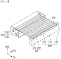
- FIG. 1 is a perspective view of a display device according to an embodiment.
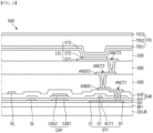
- FIG. 2 is a cross-sectional view of a display panel of FIG. 1 .
- FIG. 3 is a perspective view illustrating an operation of the display device of FIG. 1 .
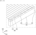
- FIG. 4 is a perspective view illustrating a first module, a second module, and a support portion of the display device of FIG. 1 .
- FIG. 5 is a perspective view illustrating in detail the first module and the support portion of FIG. 4 .
- FIG. 6 is a perspective view illustrating in detail the second module and the support portion of FIG. 4 .
- a display device may include a first module 100, a second module 200 spaced apart from the first module 100, a support portion 300, and a display panel 500.
- the first module 100 and the second module 200 may be spaced apart from each other in a first direction DR1.
- Each of the first module 100 and the second module 200 may extend along a second direction DR2 crossing the first direction DR1.
- the first direction DR1 and the second direction DR2 may be located on the same plane.
- a plane formed by the first direction DR1 and the second direction DR2 is referred to as a first plane
- a third direction DR3 is defined as a direction perpendicular to the first plane.
- the display panel 500 may include a liquid crystal display panel, an organic light emitting diode display panel, an inorganic light emitting diode display panel, or a quantum dot display panel.
- a case in which the display panel 500 is an organic light emitting diode display panel will be mainly described.
- the display panel 500 may be wound or unwound. That is, a predetermined flexibility is provided to the display panel 500, so that a rolling (or winding) or unrolling (or unwinding) operation may be easily and repeatedly performed.
- the first module 100 may include a first housing 130 and a first roller portion 120 disposed in the first housing 130.
- a plurality of support portions 300 may be provided.
- the plurality of support portions 300 may include a first support portion 310 and a second support portion 350.
- the first support portion 310 and the second support portion 350 may be spaced apart from each other in the second direction DR2.
- the first support portion 310 and the second support portion 350 may be alternately and repeatedly arranged along the second direction DR2.
- Each of the plurality of support portions 300 may have one end portion fixed to the first roller portion 120 in the first housing 130 and may extend in the first direction DR1.
- One end portion of the display panel 500 may be fixed to a second roller portion 110 to be described later.
- the present disclosure is not limited thereto, and in another embodiment, the one end portion of the support portion 300 may not be directly fixed to the first roller portion 120, but may be indirectly fixed to the first roller portion 120 by a separate fastening element.
- the first module 100 may not include the first roller portion 120, and the second module 200 may include the first roller portion 120.
- the display panel 500 may be disposed to overlap the plurality of support portions 300.
- the display panel 500 may include one surface and the other surface opposite to the one surface.
- the one surface (i.e., top surface) of the display panel 500 may be a display surface which displays an image and face upward (in the third direction DR3).
- An exemplary stacked structure of the display panel 500 is illustrated in FIG. 2 .
- the display panel 500 may include display pixels that display an image.
- Each of the display pixels may include a light emitting element LEL, a first thin film transistor ST1, and a capacitor CAP.
- a display substrate DSUB may be made of an insulating material such as glass or a polymer resin.
- the display substrate DSUB may include polyimide.
- the display substrate DSUB may be a flexible substrate that may be bent, folded, and rolled.
- the display substrate DSUB may include, for example, a plurality of organic layers and a plurality of inorganic layers.
- the display substrate DSUB may include a first organic layer, a first barrier layer disposed on the first organic layer and including at least one inorganic layer, a second organic layer disposed on the first barrier layer, and a second barrier layer disposed on the second organic layer and including at least one inorganic layer.
- a first buffer layer BF1 may be disposed on the display substrate DSUB.
- the first buffer layer BF1 is a layer for protecting the first thin film transistor ST1 and a light emitting layer 572 of the light emitting element LEL from moisture permeating through the display substrate DSUB, which is vulnerable to moisture permeation.
- a first buffer layer BF1 may include a plurality of inorganic layers.
- a first active layer ACT1, a first source electrode S1, and a first drain electrode D1 of the first thin film transistor ST1 may be disposed on the first buffer layer BF1.
- the first active layer ACT1 of the first thin film transistor ST1 includes polycrystalline silicon, single crystal silicon, low-temperature polycrystalline silicon, amorphous silicon, or an oxide semiconductor.
- the first active layer ACT1 may overlap a first gate electrode G1 in a third direction DR3 that is a thickness direction of the display substrate DSUB.
- a first gate insulating layer GI1 may be disposed on the first active layer ACT1 of the first thin film transistor ST1.
- the first gate insulating layer GI1 may be formed of an inorganic layer, for example, a silicon nitride layer, a silicon oxynitride layer, a silicon oxide layer, a titanium oxide layer, or an aluminum oxide layer.
- a first gate electrode G1 of the first thin film transistor ST1, a first capacitor electrode CAE1, and a scan line SL may be disposed on the first gate insulating layer GI1.
- the scan line SL may be electrically connected to the first gate electrode G1.
- the first capacitor electrode CAE1 may overlap a second capacitor electrode CAE2 in the third direction DR3 (i.e., in a plan view).
- a first interlayer insulating layer 541 may be disposed on the first gate electrode G1 and the first capacitor electrode CAE1.
- the first interlayer insulating layer 541 may include an inorganic layer.
- the second capacitor electrode CAE2 may be disposed on the first interlayer insulating layer 541. Since the first interlayer insulating layer 541 has a predetermined dielectric constant, a capacitor CAP may be formed by the first capacitor electrode CAE1, the second capacitor electrode CAE2, and the first interlayer insulating layer 541 disposed between the first capacitor electrode CAE1 and the second capacitor electrode CAE2.
- a second interlayer insulating layer 542 may be disposed on the second capacitor electrode CAE2.
- the second interlayer insulating layer 542 may include an inorganic layer.
- a first pixel connection electrode ANDE1 and a data line DL may be disposed on the second interlayer insulating layer 542.
- the first pixel connection electrode ANDE1 may be connected to the first drain electrode D1 of the first thin film transistor ST1 through a first pixel contact hole ANCT1 penetrating through the first interlayer insulating layer 541 and the second interlayer insulating layer 542 to expose the first drain electrode D 1 of the first thin film transistor ST1.
- a first organic layer 560 for planarization may be disposed on the first pixel connection electrode ANDE1.
- the first organic layer 560 may be formed of an acrylic resin, an epoxy resin, a phenolic resin, a polyamide resin, a polyimide resin, or the like.
- a second pixel connection electrode ANDE2 may be disposed on the first organic layer 560.
- the second pixel connection electrode ANDE2 may be connected to the first pixel connection electrode ANDE1 through a second pixel contact hole ANCT2 penetrating through the first organic layer 560 to expose the first pixel connection electrode ANDE1.
- a second organic layer 580 may be disposed on the second pixel connection electrode ANDE2.
- the second organic layer 580 may be formed of an acrylic resin, an epoxy resin, a phenolic resin, a polyamide resin, a polyimide resin, or the like.
- the first thin film transistor ST1 is formed in a top gate type in which the first gate electrode G1 is positioned above the first active layer ACT1, but it should be noted that the present disclosure is not limited thereto.
- Light emitting elements LEL and a bank 590 may be disposed on the second organic layer 580.
- Each of the light emitting elements LEL includes a light emitting pixel electrode 571, a light emitting layer 572, and a light emitting common electrode 573.
- the light emitting pixel electrode 571 may be formed on the second organic layer 580.
- the light emitting pixel electrode 571 may be connected to the second pixel connection electrode ANDE2 through a third pixel contact hole ANCT3 penetrating through the second organic layer 580 to expose the second pixel connection electrode ANDE2.
- the light emitting pixel electrode 571 may include, for example, a stacked structure (ITO/Ag/ITO) of silver and ITO.
- ITO/Ag/ITO stacked structure
- the bank 590 may be formed to partition the light emitting pixel electrode 571 on the second organic layer 580 to define an emission area EA.
- the emission area EA represents an area in which the light emitting pixel electrode 571, the light emitting layer 572, and the light emitting common electrode 573 are sequentially stacked, and holes from the light emitting pixel electrode 571 and electrons from the light emitting common electrode 573 are combined with each other in the light emitting layer 572 to emit light.
- the light emitting layer 572 is formed on the light emitting pixel electrode 571 and the bank 590.
- the light emitting layer 572 may include an organic material to emit light of a predetermined color.
- the light emitting common electrode 573 is formed on the light emitting layer 572.
- the light emitting common electrode 573 may be formed to cover the light emitting layer 572.
- the light emitting common electrode 573 may be a common layer commonly formed in all the emission areas EA.
- a capping layer may be formed on the light emitting common electrode 573.
- the light emitting common electrode 573 may be formed of transparent conductive oxide (“SCE”) such as ITO or indium zinc oxide (“IZO") capable of transmitting light, or a semi-transmissive conductive material such as magnesium (Mg), silver (Ag), or an alloy of magnesium (Mg) and silver (Ag).
- SCE transparent conductive oxide
- IZO indium zinc oxide
- Mg magnesium
- Ag silver
- Au alloy of magnesium
- Ag silver
- An encapsulation layer TFE may be disposed on the light emitting common electrode 573.
- the encapsulation layer TFE may include at least one inorganic layer to prevent oxygen or moisture from permeating into the light emitting element layer EML.
- the encapsulation layer TFE may include at least one organic layer and at least one inorganic layer in order to protect the light emitting element layer EML from foreign materials such as dust.
- the encapsulation layer TFE may include a first encapsulation inorganic layer TFE1, an encapsulation organic layer TFE2, and a second encapsulation inorganic layer TFE3.
- the second module 200 may include a second housing 230 to which the other end portion of the support portion 300 is fixed.
- the second module 200 may further include a frame 220 and a battery 210 disposed in the second housing 230.
- the other end portion of the support portion 300 and the other end portion of the display panel 500 may be fixed to the frame 220.
- the present disclosure is not limited thereto, and in another embodiment, the other end portion of the support portion 300 may not be directly fixed to the frame 220, but may be indirectly fixed to the frame 220 by a separate fastening element.
- the battery 210 may be positioned on a lower side of the frame 220. The battery 210 is included in the second module 200 and occupies most of the weight of the second module 200.
- the plurality of support portions 300 may be disposed on the other surface (i.e., bottom surface) of the display panel 500.
- the first support portion 310 may include a concave pattern which is concave in a direction (i.e., the third direction DR3) facing the other surface (i.e., bottom surface) of the display panel 500
- the second support portion 350 may include a convex pattern which is convex in the direction (i.e., the third direction DR3) facing the other surface (i.e., bottom surface) of the display panel 500.
- the first support portions 310 of the support portions 300 according to an embodiment are made of only the concave pattern, and the second support portions 350 thereof are made of only the convex pattern.
- the second module 200 may move to be close to or away from the first module 100 in the first direction DR1.
- the support portions 300 may be wound around the first roller portion 120, and as the second module 200 moves away from the first module 100, the support portions 300 may be unwound from the first roller portion 120.
- the concave pattern thereof may be unrolled
- the convex pattern thereof may be unrolled. That is, when the first support portion 310 and the second support portion 350 are wound around the first roller portion 120, the concave pattern of the first support portion 310 and the convex portion of the second support portion 350 are flatten to be wound around the first roller portion 120.
- the first support portion 310 when the first support portion 310 is unwound from the first roller portion 120, the first support portion 310 may recover the concave pattern in an unrolled state, and when the second support portion 350 is unwound from the first roller portion 120, the second support portion 350 may recover the convex pattern in an unrolled state.
- the first module 100 may further include a second roller portion 110 disposed in the first housing 130 and spaced apart from the first roller portion 120.
- the display panel 500 may be more wound around the second roller portion 110, and as the second module 200 moves away from the first module 100, the display panel 500 may be unwound from the second roller portion 110.
- the support portion 300 is unwound from the first roller portion 120, the first support portion 310 recovers and maintains the concave pattern, and the second support portion 350 recovers and maintains the convex pattern.
- a user may use the display panel 500 in a method in which the user holds the first module 100 of the display device, moves the second module 200 in a direction (e.g., the direction opposite to the first direction DR1) away from the first module 100, and then views the display surface (or one surface) of the unwound display panel 500 or presses the display surface.
- the unwound display panel 500 may droop downward.
- the display surface pressed by the user may be drooped downward.
- the support portion 300 since the support portion 300 according to an embodiment includes the second support portion 350 having the convex pattern which is convex in the direction (e.g., the third direction DR3) facing the other surface (i.e., bottom surface) of the display panel 500 as described above, it is possible to prevent the unwound display panel 500 from drooping downward by improving the support characteristics of the unwound support portion 300 supporting the display panel 500.
- the first support portion 310 having the concave pattern may prevent the second module 200 from drooping downward.
- the second module 200 further includes the battery 210 disposed in the second housing 230, which may occupy a significant weight of the second module 200.
- the second module 200 including the battery 210 may droop downward.
- the support portion 300 since the support portion 300 according to an embodiment further includes the first support portion 310 having the concave pattern, it is possible to prevent the second module 200 from drooping downward.
- first and second support portions 310 and 350 are not limited thereto.
- the first support portion 310 having the concave pattern may also prevent the unwound display panel 500 from drooping downward by improving the support characteristics of the unwound support portion 300 supporting the display panel 500, and the second support portion 350 having the convex pattern may also prevent the second module 200 from drooping downward.
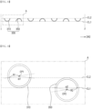
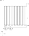
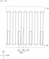
- FIG. 7 is a plan view of the first module, the second module, and the support portion of FIG. 4 .
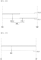
- FIG. 8 is a cross-sectional view taken along line I-I' of FIG. 7 .
- FIG. 9 is an enlarged cross-sectional view of area A of FIG. 8 .
- FIG. 10 is a cross-sectional view illustrating a state in which a display panel is disposed on the support portion of FIG. 8 .
- the "plan view" may be defined as a view from the third direction DR3.
- each of the first support portion 310 and the second support portion 350 may have a first width W1 in the second direction DR2.
- the first support portion 310 and the second support portion 350 may be alternately and repeatedly arranged along the second direction DR2.
- the present disclosure is not limited thereto, and in another embodiment, the first support portion 310 and the second support portion 350 are not alternately arranged, and two or more first support portions 310 may be continuously arranged along the second direction DR2, and then the second support portion 350 may be disposed, or two or more second support portions 350 may be continuously arranged along the second direction DR2, and then the first support portion 310 may also be disposed.
- the first support portion 310 and the second support portion 350 adjacent to each other are spaced apart from each other with a predetermined separation distance along the second direction DR2, and the separation distance may be set so that the wound first support portion 310 and the wound second support portion 350 adjacent to each other do not come into contact with each other.
- a first virtual extension line CL1 and a second virtual extension line CL2 each extending in the second direction DR2 are defined.
- the second virtual extension line CL2 is positioned above the first virtual extension line CL1.
- the first virtual extension line CL1 and the second virtual extension line CL2 are introduced to explain the arrangement of the first support portion 310 and the second support portion 350 more clearly.
- the most concave portion of the first support portion 310 may be in contact with the first virtual extension line CL1, and the most convex portion of the second support portion 350 may be in contact with the second virtual extension line CL2.
- each of the first support portion 310 and the second support portion 350 may have a cross-sectional shape having an arc shape.
- Central angles of the arc shapes of the first support portion 310 and the second support portion 350 may be equal to each other.
- the central angles ⁇ 1 and ⁇ 2 of the arc shapes with respect to the centers CP1 and CP2 may be the same and be greater than 90 degrees and smaller than 180 degrees.
- the central angle may be about 130 degrees.
- radii of curvature R1 and R2 of the first support portion 310 and the second support portion 350 may be equal to each other.
- the display panel 500 may be disposed and supported on the first and second support portions 310 and 350.
- the support portion 300 includes the second support portion 350 having the convex pattern which is convex in the direction facing the other surface (i.e., the bottom surface) of the display panel 500, it is possible to prevent the unwound display panel 500 from drooping downward by improving the support characteristics of the unwound support portion 300 supporting the display panel 500, and the first support portion 310 having the concave pattern may prevent the second module 200 from drooping downward.
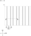
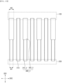
- FIG. 11 is a plan view of a first module, a second module, and a support portion according to another embodiment.
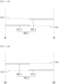
- FIG. 12 is a cross-sectional view taken along line II-II' of FIG. 11 .
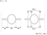
- the present embodiment is different from the embodiment of FIGS. 7 and 8 in that support portions 310_1 and 350_1 of the display device according to the present embodiment further include a sub-support portion, respectively.
- a first support portion 310_1 may include the first support portion 310 (or concave pattern) of FIG. 7 and first sub-support portions 311 and 312 connected to the first support portion 310
- a second support portion 350_1 may include the second support portion 350 (or convex pattern) of FIG. 7 and second sub-support portions 351 and 352 connected to the second support portion 350.
- the first sub-support portions 311 and 312 may be aligned with the second virtual extension line CL2, and the second sub-support portions 351 and 352 may be aligned with the first virtual extension line CL1.
- the first sub-support portions 311 and 312 and the uppermost convex portion of the second support portion 350 may support the display panel 500 of FIG. 10 .
- the first support portion 310 and the second support portion 350 may each have a predetermined width W2, the first sub-support portion 311 and the second sub-support portion 351 may have predetermined width W3, and the first sub-support portion 312 and the second sub-support portion 352 may have predetermined width W4 in the second direction DR2.
- the width W2 of the first support portion 310 may be greater than a sum of the width W3 of the first sub-support portion 311 and the width W4 of the first sub-support portion 312, and the width W2 of the second support portion 350 may be greater than a sum of the width W3 of the second sub-support portion 351 and the width W4 of the second sub-support portion 352.
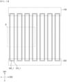
- FIG. 13 is a plan view of a first module, a second module, and a support portion according to still another embodiment.
- FIG. 14 is an enlarged plan view of a partial area of FIG. 13 .
- FIG. 15 is a cross-sectional view taken along line III-III' of FIG. 14 .
- a support portion 360 according to the present embodiment is different from the support portion 300 of FIGS. 7 and 8 in that first and second support portions 360 have the same shape.
- each of support portions 360 may include the first support portion 310_1 and the second support portion 350_1 of FIGS. 11 and 12 .
- the second support portion 350_1 may be positioned between the first support portion 310_1 and the display panel (500 in FIG. 10 ).
- the first sub-support portion 311 and the second sub-support portion 351 may be in contact with each other, and the first sub-support portion 312 and the second sub-support portion 352 may be in contact with each other.
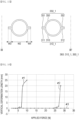
- FIG. 16 is a graph illustrating a vertical deformation length of a display panel according to a force applied to the display device.
- a horizontal axis of the graph of FIG. 16 represents a force (or applied force (newton: N)) that presses the display surface of the unwound display panel 500 from above
- a vertical axis represents a vertical (or downward DR3) deformation length (millimeters: mm) of the display panel 500
- the graph of FIG. 16 illustrates a first embodiment (#1), a second embodiment (#2), and a third embodiment (#3).
- the first embodiment (#1) is a case in which the support portion is applied only as the concave pattern in FIG.
- the second embodiment (#2) is a case in which the support portion 300 in which the convex pattern and the concave pattern of FIG. 1 are alternately disposed is applied
- the third embodiment (#3) is a case in which the support portion 360 of FIG. 15 is applied.
- FIG. 16 is a cross-sectional view illustrating another example of a first support portion and a second support portion according to FIG. 15 .
- the present embodiment is different from the embodiment of FIG. 15 in that the predetermined width W2 may be equal to or smaller than the sum of the widths W3 and W4.
- FIG. 18 is a plan view of a first module, a second module, and a support portion according to still another embodiment.
- FIG. 19 is a cross-sectional view taken along line IV-IV' of FIG. 18 .
- FIG. 20 is a cross-sectional view taken along line V-V' of FIG. 18 .
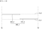
- FIG. 21 is a cross-sectional view taken along line VI-VI' of FIG. 18 .
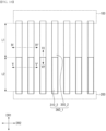
- the present embodiment is different from the embodiment of FIGS. 7 and 8 in that a first support portion and a second support portion next to the first support portion in the second direction DR2 have the same shape, and the first support portion and the second support portion each have a convex pattern and a concave pattern mixed with each other.
- first support portion and the second support portion will be collectively called as "support portion 360_1".
- each of the support portions 360_1 may include a concave pattern 310_2 and a convex pattern 350_2.
- the convex pattern 350_2 may be disposed between the concave pattern 310_2 and the first module 100 in a cross-sectional view such as FIGS. 19 and 20 .
- An end portion of the other side of the convex pattern 350_2 in the first direction DR1 may be directly connected to an end portion of one side of the concave pattern 310_2 in the first direction DR1 as shown in FIG. 18 .
- a length L1 (in the first direction DR1) of a portion of the convex pattern 350_2 that does not overlap the first module 100 in a plan view may be the same as a length L2 of the portion of the concave pattern 310_2 that does not overlap the second module 200.
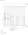
- FIG. 22 is a plan view of a first module, a second module, and a support portion according to still another embodiment.
- the present embodiment is different from the embodiment of FIG. 18 in that in the support portions 360_1 of the display device according to the present embodiment, a length L1' of a portion of the convex pattern 350_2 that does not overlap the first module 100 in a plan view is greater than a length L2' of the portion of the concave pattern 310_2 that does not overlap the second module 200.
- FIG. 23 is a plan view of a first module, a second module, and a support portion according to still another embodiment.
- FIG. 24 is a cross-sectional view taken along line VII-VII' of FIG. 23 .
- the present embodiment is different from the embodiment of FIG. 22 in that a width W5 of a concave pattern 310_3 of a support portion 360_2 of the display device according to the present embodiment in the second direction DR2 is greater than a width W1 of a convex pattern 350_2 thereof in the second direction DR2.
- FIG. 25 is a plan view of a first module, a second module, and a support portion according to still another embodiment.
- FIG. 26 is a cross-sectional view taken along line VIII-VIII' of FIG. 25 .
- FIG. 27 is a cross-sectional view taken along line IX-IX' of FIG. 25 .
- FIG. 28 is a cross-sectional view taken along line X-X' of FIG. 25 .
- the present embodiment is different from the embodiment of FIGS. 18 to 21 in that support portions 360_1 and 350 of the display device according to the present embodiment include the first support portion 360_1 of FIG. 18 and the second support portion 350 of FIG. 7 .
- first support portion 360_1 is described above with reference to FIG. 18 and the second support portion 350 is described above with reference to FIG. 7 , the detailed descriptions thereof will be omitted.
- FIG. 29 is a plan view of a first module, a second module, and a support portion according to still another embodiment.
- the present embodiment is different from the embodiment of FIG. 25 in that the support portions 360_1 and 350 of the display device according to the present embodiment have the same first support portion 360_1 as the first support portion 360_1 of FIG. 22 .
- FIG. 30 is a plan view of a first module, a second module, and a support portion according to still another embodiment.
- FIG. 31 is a cross-sectional view taken along line XI-XI' of FIG. 30 .
- FIG. 32 is a cross-sectional view taken along line XII-XII' of FIG. 30 .
- FIG. 33 is a cross-sectional view taken along line XIII-XIII' of FIG. 30 .
- FIG. 34 is a cross-sectional view taken along line XIV-XIV' of FIG. 30 .
- support portions 360_2 and 360_3 of the display device according to the present embodiment include a first support portion 360_2 and a second support portion 360_3.
- the first support portion 360_2 may include a concave pattern 310_2 and a convex pattern 350_2 positioned between the concave pattern 310_2 and the second module 200 in a plan view, and the second support portion 360_3 may have the same shape as the second support portion 360_1 of FIG. 18 .
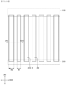
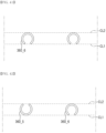
- support portions 310 and 360_4 may include a first support portion 310 and a second support portion 360_4.
- the second support portion 360_4 may include a convex pattern 350_3 having a predetermined width W5 in the second direction DR2 and a concave pattern 310_2 disposed between the convex pattern 350_3 and the second module 200 in a plan view.
- An end portion of the other side of the convex pattern 350_3 in the first direction DR1 may be directly connected to an end portion of one side of the concave pattern 310_2 in the first direction DR1.
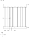
- FIG. 36 is a plan view of a first module, a second module, and a support portion according to still another embodiment.
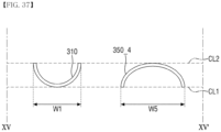
- FIG. 37 is a cross-sectional view taken along line XV-XV' of FIG. 36 .
- a predetermined width W5 of the second support portion 350_4 may be greater than a predetermined width W1 of the first support portion 310.
- FIG. 38 is a plan view of a first module, a second module, and a support portion according to still another embodiment.
- FIG. 39 is a cross-sectional view taken along line XVI-XVI' of FIG. 38 .
- support portions 310_3 and 350 may include a first support portion 310_3 and a second support portion 350.
- FIG. 40 is a cross-sectional view illustrating a first support portion and a second support portion according to still another embodiment.
- each of first and second support portions 360_5 of the support portion of the display device according to the present embodiment has an arc shape, and a central angle ⁇ 3 of the arc shape is greater than 180 degrees and smaller than 360 degrees.
- the first and second support portion 360_5 since the first and second support portion 360_5 have the concave pattern which is concave in the upward direction and have the arc shape, and the central angle ⁇ 3 of the arc shape is greater than 180 degrees and smaller than 360 degrees, the first and second support portions 360_5 may have the support characteristics by the first support portion 310 of FIG. 8 and the support characteristics by the second support portion 350 at the same time.
- FIG. 41 is a cross-sectional view illustrating a first support portion and a second support portion according to still another embodiment.
- first and second support portions 360_6 of the support portion of the display device according to the present embodiment have a convex pattern which is convex in an upward direction, respectively.
- the first and second support portion 360_6 since the first and second support portion 360_6 have the convex pattern which is convex in the upward direction and have an arc shape, and a central angle ⁇ 3 of the arc shape is greater than 180 degrees and smaller than 360 degrees, the first and second support portions 360_6 may have the support characteristics by the first support portion 310 of FIG. 8 and the support characteristics by the second support portion 350 at the same time.
- FIG. 42 is a cross-sectional view illustrating a first support portion and a second support portion according to still another embodiment.
- the present embodiment is different from the embodiment of FIG. 40 in that support portions 360_5 and 360_6 according to the present embodiment have the first support portion 360_5 and the second support portion 360_6.
- first support portion 360_5 is described above with reference to FIG. 40 and the second support portion 360_6 is described above with reference to FIG. 41 , the detailed descriptions thereof will be omitted.
- FIG. 43 is a perspective view of a display device according to still another embodiment.
- a display device is different from the display device of FIG. 1 in that a first module 100_1 does not include the first roller portion (see 120 in FIG. 1 ) and a second module 200_1 includes a first roller portion 240.
- the other end portion of the support portion 300 may be fixed to the first roller portion 240. Furthermore, one end portion of the support portion 300 may be fixed to the first housing 130.
- the battery (210 in FIG. 1 ) and the frame (220 in FIG. 1 ) may be omitted. However, the present disclosure is not limited thereto, and the battery 210 and the frame 220 may also not be omitted.
- the second module 200_1 may move away from the first module 100_1 when the display panel 500 is unwound.
Landscapes
- Engineering & Computer Science (AREA)
- Physics & Mathematics (AREA)
- General Physics & Mathematics (AREA)
- Theoretical Computer Science (AREA)
- Optics & Photonics (AREA)
- Computer Hardware Design (AREA)
- Nonlinear Science (AREA)
- Microelectronics & Electronic Packaging (AREA)
- Crystallography & Structural Chemistry (AREA)
- Signal Processing (AREA)
- Chemical & Material Sciences (AREA)
- Human Computer Interaction (AREA)
- General Engineering & Computer Science (AREA)
- Mathematical Physics (AREA)
- Devices For Indicating Variable Information By Combining Individual Elements (AREA)
Abstract
Description
- The present disclosure relates to a display device.
- With the development of information technology, the market for display devices, which is a connection medium between users and information, is growing. Accordingly, the use of display devices such as an organic light emitting diode display ("OLED") and a liquid crystal display ("LCD") is increasing.
- Among the display devices, since the organic light emitting diode display is a self-light emitting device, it consumes less power and may be made thinner than the liquid crystal display that requires a backlight. In addition, the organic light emitting diode display has an advantage in that a viewing angle is wide and a response speed is fast.
- A flexible display device has been commercialized. The flexible display device may reproduce an input image on a screen of a display panel on which a plastic OLED is formed. The plastic OLED is formed on a flexible plastic substrate. The flexible display device may implement various designs and has advantages in portability and durability. The flexible display device may be implemented as various types of display devices, such as a bendable display device, a foldable display device, and a rollable display device. Such a flexible display device may be applied not only to mobile devices such as smart phones and tablet PCs, but also to televisions ("TVs"), automobile display devices, wearable devices, and the like, and a field of application thereof is expanding.
- In the rollable display device, the display panel may be wound, and the display panel may be used by being unrolled. When the user intends to use the display panel, the display panel is desirable to be maintained in an unrolled state. The conventional rollable display device does not include a fixing mechanism for maintaining the display panel in the unrolled state, so that the display panel may be wound during use, contrary to the user's intention. The absence of such a mechanism has a problem that may reduce the user's convenience of use.
- Aspects of the present disclosure provide a display device capable of improving a drooping phenomenon of the display device in a state in which the display device is unrolled in a horizontal direction with respect to the ground.
- However, aspects of the present disclosure are not restricted to those set forth herein. The above and other aspects of the present disclosure will become more apparent to one of ordinary skill in the art to which the present disclosure pertains by referencing the detailed description of the present disclosure given below.
- According to an aspect of the present disclosure, a display device includes: a first module including a first housing and a first roller portion disposed in the first housing; a plurality of support portions having one end portion fixed to the first roller portion in the first housing and extending in a first direction; a display panel disposed to overlap the plurality of support portions and including one surface and the other surface opposite to the one surface; and a second module including a second housing to which the other end portions of the plurality of support portions are fixed, wherein the plurality of support portions are disposed on the other surface of the display panel, the plurality of support portions include a first support portion, and a second support portion spaced apart from the first support portion in a second direction intersecting the first direction, the first support portion includes a concave pattern which is concave in a direction facing the other surface of the display panel, and the second support portion includes a convex pattern which is convex in the direction facing the other surface of the display panel.
- According to another aspect of the present disclosure, a display device includes: a first module including a first housing and a first roller portion disposed in the first housing and on or from which a display panel is wound or unwound; a second module including a second housing and a second roller portion disposed in the second housing, and moving away from the first module when the display panel is wound; a plurality of support portions having one end portion fixed to the second roller portion and extending in a first direction to have the other end portion fixed to the first housing; and the display panel disposed to overlap the plurality of support portions and including one surface and the other surface opposite to the one surface, wherein the plurality of support portions are disposed on the other surface of the display panel, the plurality of support portions include a first support portion, and a second support portion spaced apart from the first support portion in a second direction intersecting the first direction, the first support portion includes a concave pattern which is concave in a direction facing the other surface of the display panel, and the second support portion includes a convex pattern which is convex in the direction facing the other surface of the display panel.
- According to the display device according to the embodiment, the drooping phenomenon may be reduced in a state in which the display device is unrolled in the horizontal direction with respect to the ground.
- However, the effects of the embodiments are not restricted to the one set forth herein. The above and other effects of the embodiments will become more apparent to one of daily skill in the art to which the embodiments pertain by referencing the claims.
-
-
FIG. 1 is a perspective view of a display device according to an embodiment; -
FIG. 2 is a cross-sectional view of a display panel ofFIG. 1 ; -
FIG. 3 is a perspective view illustrating an operation of the display device ofFIG. 1 ; -
FIG. 4 is a perspective view illustrating a first module, a second module, and a support portion of the display device ofFIG. 1 ; -
FIG. 5 is a perspective view illustrating in detail the first module and the support portion ofFIG. 4 ; -
FIG. 6 is a perspective view illustrating in detail the second module and the support portion ofFIG. 4 ; -
FIG. 7 is a plan view of the first module, the second module, and the support portion ofFIG. 4 ; -
FIG. 8 is a cross-sectional view taken along line I-I' ofFIG. 7 ; -
FIG. 9 is an enlarged cross-sectional view of area A ofFIG. 8 ; -
FIG. 10 is a cross-sectional view illustrating a state in which a display panel is disposed on the support portion ofFIG. 8 ; -
FIG. 11 is a plan view of a first module, a second module, and a support portion according to another embodiment; -
FIG. 12 is a cross-sectional view taken along line II-II' ofFIG. 11 ; -
FIG. 13 is a plan view of a first module, a second module, and a support portion according to still another embodiment; -
FIG. 14 is an enlarged plan view of a partial area B ofFIG. 13 ; -
FIG. 15 is a cross-sectional view taken along line III-III' ofFIG. 14 ; -
FIG. 16 is a graph illustrating a vertical deformation length (or Y-axis deformation length) of a display panel versus a force applied to the display device; -
FIG. 17 is a cross-sectional view illustrating another example of a first support portion and a second support portion according toFIG. 15 ; -
FIG. 18 is a plan view of a first module, a second module, and a support portion according to still another embodiment; -
FIG. 19 is a cross-sectional view taken along line IV-IV' ofFIG. 18 ; -
FIG. 20 is a cross-sectional view taken along line V-V' ofFIG. 18 ; -
FIG. 21 is a cross-sectional view taken along line VI-VI' ofFIG. 18 ; -
FIG. 22 is a plan view of a first module, a second module, and a support portion according to still another embodiment; -
FIG. 23 is a plan view of a first module, a second module, and a support portion according to still another embodiment; -
FIG. 24 is a cross-sectional view taken along line VII-VII' ofFIG. 23 ; -
FIG. 25 is a plan view of a first module, a second module, and a support portion according to still another embodiment; -
FIG. 26 is a cross-sectional view taken along line VIII-VIII' ofFIG. 25 ; -
FIG. 27 is a cross-sectional view taken along line IX-IX' ofFIG. 25 ; -
FIG. 28 is a cross-sectional view taken along line X-X' ofFIG. 25 ; -
FIG. 29 is a plan view of a first module, a second module, and a support portion according to still another embodiment; -
FIG. 30 is a plan view of a first module, a second module, and a support portion according to still another embodiment; -
FIG. 31 is a cross-sectional view taken along line XI-XI' ofFIG. 30 ; -
FIG. 32 is a cross-sectional view taken along line XII-XII' ofFIG. 30 ; -
FIG. 33 is a cross-sectional view taken along line XIII-XIII' ofFIG. 30 ; -
FIG. 34 is a cross-sectional view taken along line XIV-XIV' ofFIG. 30 ; -
FIG. 35 is a plan view of a first module, a second module, and a support portion according to still another embodiment; -
FIG. 36 is a plan view of a first module, a second module, and a support portion according to still another embodiment; -
FIG. 37 is a cross-sectional view taken along line XV-XV' ofFIG. 36 ; -
FIG. 38 is a plan view of a first module, a second module, and a support portion according to still another embodiment; -
FIG. 39 is a cross-sectional view taken along line XVI-XVI' ofFIG. 38 ; -
FIG. 40 is a cross-sectional view illustrating a first support portion and a second support portion according to still another embodiment; -
FIG. 41 is a cross-sectional view illustrating a first support portion and a second support portion according to still another embodiment; -
FIG. 42 is a cross-sectional view illustrating a first support portion and a second support portion according to still another embodiment; and -
FIG. 43 is a perspective view of a display device according to still another embodiment. - Advantages and features of the present disclosure and methods of accomplishing the same may be understood more readily by reference to the following detailed description of preferred embodiments and the accompanying drawings. The present disclosure may, however, be embodied in many different forms and should not be construed as being limited to the embodiments set forth herein. Rather, these embodiments are provided so that this disclosure will be thorough and complete and will fully convey the concept of the invention to those skilled in the art, and the present disclosure will only be defined by the appended claims.
- When an element or layer is referred to as being "on" another element or layer, it may be directly on the other element or layer or intervening elements or layers may be present. In contrast, when an element is referred to as being "directly on" another element, there are no intervening elements present. The same reference numbers indicate the same components throughout the specification.
- Although the terms first, second, , etc. may be used herein to describe various components, these components should not be limited by these terms. These terms are used to distinguish one component from another component. Thus, a first component discussed below could be termed a second component without departing from the teachings of the present disclosure.
- Each feature of the various embodiments of the present invention can be combined or combined with each other, partially or entirely, and various technical interconnections and operations are possible, and each embodiment may be implemented independently of each other or together in a related relationship.
- Hereinafter, exemplary embodiments will be described in detail with reference to the accompanying drawings.
-
FIG. 1 is a perspective view of a display device according to an embodiment.FIG. 2 is a cross-sectional view of a display panel ofFIG. 1 .FIG. 3 is a perspective view illustrating an operation of the display device ofFIG. 1 .FIG. 4 is a perspective view illustrating a first module, a second module, and a support portion of the display device ofFIG. 1 .FIG. 5 is a perspective view illustrating in detail the first module and the support portion ofFIG. 4 .FIG. 6 is a perspective view illustrating in detail the second module and the support portion ofFIG. 4 . - Referring to
FIGS. 1 to 6 , a display device according to an embodiment may include afirst module 100, asecond module 200 spaced apart from thefirst module 100, asupport portion 300, and adisplay panel 500. Thefirst module 100 and thesecond module 200 may be spaced apart from each other in a first direction DR1. Each of thefirst module 100 and thesecond module 200 may extend along a second direction DR2 crossing the first direction DR1. The first direction DR1 and the second direction DR2 may be located on the same plane. In the present specification, a plane formed by the first direction DR1 and the second direction DR2 is referred to as a first plane, and a third direction DR3 is defined as a direction perpendicular to the first plane. - The
display panel 500 may include a liquid crystal display panel, an organic light emitting diode display panel, an inorganic light emitting diode display panel, or a quantum dot display panel. Hereinafter, for convenience of description, a case in which thedisplay panel 500 is an organic light emitting diode display panel will be mainly described. - The
display panel 500 may be wound or unwound. That is, a predetermined flexibility is provided to thedisplay panel 500, so that a rolling (or winding) or unrolling (or unwinding) operation may be easily and repeatedly performed. - The
first module 100 may include afirst housing 130 and afirst roller portion 120 disposed in thefirst housing 130. A plurality ofsupport portions 300 may be provided. The plurality ofsupport portions 300 may include afirst support portion 310 and asecond support portion 350. Thefirst support portion 310 and thesecond support portion 350 may be spaced apart from each other in the second direction DR2. Thefirst support portion 310 and thesecond support portion 350 may be alternately and repeatedly arranged along the second direction DR2. - Each of the plurality of
support portions 300 may have one end portion fixed to thefirst roller portion 120 in thefirst housing 130 and may extend in the first direction DR1. One end portion of thedisplay panel 500 may be fixed to asecond roller portion 110 to be described later. However, the present disclosure is not limited thereto, and in another embodiment, the one end portion of thesupport portion 300 may not be directly fixed to thefirst roller portion 120, but may be indirectly fixed to thefirst roller portion 120 by a separate fastening element. - In some embodiments, the
first module 100 may not include thefirst roller portion 120, and thesecond module 200 may include thefirst roller portion 120. - The
display panel 500 may be disposed to overlap the plurality ofsupport portions 300. Thedisplay panel 500 may include one surface and the other surface opposite to the one surface. The one surface (i.e., top surface) of thedisplay panel 500 may be a display surface which displays an image and face upward (in the third direction DR3). An exemplary stacked structure of thedisplay panel 500 is illustrated inFIG. 2 . - As illustrated in
FIG. 2 , thedisplay panel 500 may include display pixels that display an image. Each of the display pixels may include a light emitting element LEL, a first thin film transistor ST1, and a capacitor CAP. - A display substrate DSUB may be made of an insulating material such as glass or a polymer resin. For example, the display substrate DSUB may include polyimide. The display substrate DSUB may be a flexible substrate that may be bent, folded, and rolled.
- The display substrate DSUB may include, for example, a plurality of organic layers and a plurality of inorganic layers. For example, the display substrate DSUB may include a first organic layer, a first barrier layer disposed on the first organic layer and including at least one inorganic layer, a second organic layer disposed on the first barrier layer, and a second barrier layer disposed on the second organic layer and including at least one inorganic layer.
- A first buffer layer BF1 may be disposed on the display substrate DSUB. The first buffer layer BF1 is a layer for protecting the first thin film transistor ST1 and a
light emitting layer 572 of the light emitting element LEL from moisture permeating through the display substrate DSUB, which is vulnerable to moisture permeation. A first buffer layer BF1 may include a plurality of inorganic layers. - A first active layer ACT1, a first source electrode S1, and a first drain electrode D1 of the first thin film transistor ST1 may be disposed on the first buffer layer BF1. The first active layer ACT1 of the first thin film transistor ST1 includes polycrystalline silicon, single crystal silicon, low-temperature polycrystalline silicon, amorphous silicon, or an oxide semiconductor. The first active layer ACT1 may overlap a first gate electrode G1 in a third direction DR3 that is a thickness direction of the display substrate DSUB.
- A first gate insulating layer GI1 may be disposed on the first active layer ACT1 of the first thin film transistor ST1. The first gate insulating layer GI1 may be formed of an inorganic layer, for example, a silicon nitride layer, a silicon oxynitride layer, a silicon oxide layer, a titanium oxide layer, or an aluminum oxide layer.
- A first gate electrode G1 of the first thin film transistor ST1, a first capacitor electrode CAE1, and a scan line SL may be disposed on the first gate insulating layer GI1. The scan line SL may be electrically connected to the first gate electrode G1. The first capacitor electrode CAE1 may overlap a second capacitor electrode CAE2 in the third direction DR3 (i.e., in a plan view).
- A first
interlayer insulating layer 541 may be disposed on the first gate electrode G1 and the first capacitor electrode CAE1. The firstinterlayer insulating layer 541 may include an inorganic layer. - The second capacitor electrode CAE2 may be disposed on the first
interlayer insulating layer 541. Since the firstinterlayer insulating layer 541 has a predetermined dielectric constant, a capacitor CAP may be formed by the first capacitor electrode CAE1, the second capacitor electrode CAE2, and the firstinterlayer insulating layer 541 disposed between the first capacitor electrode CAE1 and the second capacitor electrode CAE2. - A second
interlayer insulating layer 542 may be disposed on the second capacitor electrode CAE2. The secondinterlayer insulating layer 542 may include an inorganic layer. - A first pixel connection electrode ANDE1 and a data line DL may be disposed on the second
interlayer insulating layer 542. The first pixel connection electrode ANDE1 may be connected to the first drain electrode D1 of the first thin film transistor ST1 through a first pixel contact hole ANCT1 penetrating through the firstinterlayer insulating layer 541 and the secondinterlayer insulating layer 542 to expose the firstdrain electrode D 1 of the first thin film transistor ST1. - A first
organic layer 560 for planarization may be disposed on the first pixel connection electrode ANDE1. The firstorganic layer 560 may be formed of an acrylic resin, an epoxy resin, a phenolic resin, a polyamide resin, a polyimide resin, or the like. - A second pixel connection electrode ANDE2 may be disposed on the first
organic layer 560. The second pixel connection electrode ANDE2 may be connected to the first pixel connection electrode ANDE1 through a second pixel contact hole ANCT2 penetrating through the firstorganic layer 560 to expose the first pixel connection electrode ANDE1. - A second
organic layer 580 may be disposed on the second pixel connection electrode ANDE2. The secondorganic layer 580 may be formed of an acrylic resin, an epoxy resin, a phenolic resin, a polyamide resin, a polyimide resin, or the like. - It has been illustrated that the first thin film transistor ST1 is formed in a top gate type in which the first gate electrode G1 is positioned above the first active layer ACT1, but it should be noted that the present disclosure is not limited thereto.
- Light emitting elements LEL and a
bank 590 may be disposed on the secondorganic layer 580. Each of the light emitting elements LEL includes a light emittingpixel electrode 571, alight emitting layer 572, and a light emittingcommon electrode 573. - The light emitting
pixel electrode 571 may be formed on the secondorganic layer 580. The light emittingpixel electrode 571 may be connected to the second pixel connection electrode ANDE2 through a third pixel contact hole ANCT3 penetrating through the secondorganic layer 580 to expose the second pixel connection electrode ANDE2. - In a top emission structure that emits light in a direction of the light emitting
common electrode 573 based on thelight emitting layer 572, the light emittingpixel electrode 571 may include, for example, a stacked structure (ITO/Ag/ITO) of silver and ITO. However, the present disclosure is not limited thereto. - The
bank 590 may be formed to partition the light emittingpixel electrode 571 on the secondorganic layer 580 to define an emission area EA. - The emission area EA represents an area in which the light emitting
pixel electrode 571, thelight emitting layer 572, and the light emittingcommon electrode 573 are sequentially stacked, and holes from the light emittingpixel electrode 571 and electrons from the light emittingcommon electrode 573 are combined with each other in thelight emitting layer 572 to emit light. - The
light emitting layer 572 is formed on the light emittingpixel electrode 571 and thebank 590. Thelight emitting layer 572 may include an organic material to emit light of a predetermined color. - The light emitting
common electrode 573 is formed on thelight emitting layer 572. The light emittingcommon electrode 573 may be formed to cover thelight emitting layer 572. The light emittingcommon electrode 573 may be a common layer commonly formed in all the emission areas EA. A capping layer may be formed on the light emittingcommon electrode 573. - In the top emission structure, the light emitting
common electrode 573 may be formed of transparent conductive oxide ("SCE") such as ITO or indium zinc oxide ("IZO") capable of transmitting light, or a semi-transmissive conductive material such as magnesium (Mg), silver (Ag), or an alloy of magnesium (Mg) and silver (Ag). - An encapsulation layer TFE may be disposed on the light emitting
common electrode 573. The encapsulation layer TFE may include at least one inorganic layer to prevent oxygen or moisture from permeating into the light emitting element layer EML. In addition, the encapsulation layer TFE may include at least one organic layer and at least one inorganic layer in order to protect the light emitting element layer EML from foreign materials such as dust. For example, the encapsulation layer TFE may include a first encapsulation inorganic layer TFE1, an encapsulation organic layer TFE2, and a second encapsulation inorganic layer TFE3. - Referring to
FIG. 1 , thesecond module 200 may include asecond housing 230 to which the other end portion of thesupport portion 300 is fixed. Thesecond module 200 may further include aframe 220 and abattery 210 disposed in thesecond housing 230. The other end portion of thesupport portion 300 and the other end portion of thedisplay panel 500 may be fixed to theframe 220. However, the present disclosure is not limited thereto, and in another embodiment, the other end portion of thesupport portion 300 may not be directly fixed to theframe 220, but may be indirectly fixed to theframe 220 by a separate fastening element. Thebattery 210 may be positioned on a lower side of theframe 220. Thebattery 210 is included in thesecond module 200 and occupies most of the weight of thesecond module 200. - The plurality of
support portions 300 may be disposed on the other surface (i.e., bottom surface) of thedisplay panel 500. Thefirst support portion 310 may include a concave pattern which is concave in a direction (i.e., the third direction DR3) facing the other surface (i.e., bottom surface) of thedisplay panel 500, and thesecond support portion 350 may include a convex pattern which is convex in the direction (i.e., the third direction DR3) facing the other surface (i.e., bottom surface) of thedisplay panel 500. Thefirst support portions 310 of thesupport portions 300 according to an embodiment are made of only the concave pattern, and thesecond support portions 350 thereof are made of only the convex pattern. - As illustrated in
FIG. 3 , thesecond module 200 may move to be close to or away from thefirst module 100 in the first direction DR1. - As the
second module 200 is close to thefirst module 100, thesupport portions 300 may be wound around thefirst roller portion 120, and as thesecond module 200 moves away from thefirst module 100, thesupport portions 300 may be unwound from thefirst roller portion 120. When thefirst support portion 310 is wound around thefirst roller portion 120, the concave pattern thereof may be unrolled, and when thesecond support portion 350 is wound around thefirst roller portion 120, the convex pattern thereof may be unrolled. That is, when thefirst support portion 310 and thesecond support portion 350 are wound around thefirst roller portion 120, the concave pattern of thefirst support portion 310 and the convex portion of thesecond support portion 350 are flatten to be wound around thefirst roller portion 120. In addition, when thefirst support portion 310 is unwound from thefirst roller portion 120, thefirst support portion 310 may recover the concave pattern in an unrolled state, and when thesecond support portion 350 is unwound from thefirst roller portion 120, thesecond support portion 350 may recover the convex pattern in an unrolled state. - The
first module 100 according to an embodiment may further include asecond roller portion 110 disposed in thefirst housing 130 and spaced apart from thefirst roller portion 120. - As the
second module 200 is close to thefirst module 100, thedisplay panel 500 may be more wound around thesecond roller portion 110, and as thesecond module 200 moves away from thefirst module 100, thedisplay panel 500 may be unwound from thesecond roller portion 110. When thedisplay panel 500 is unwound from thesecond roller portion 110, thesupport portion 300 is unwound from thefirst roller portion 120, thefirst support portion 310 recovers and maintains the concave pattern, and thesecond support portion 350 recovers and maintains the convex pattern. - A user may use the
display panel 500 in a method in which the user holds thefirst module 100 of the display device, moves thesecond module 200 in a direction (e.g., the direction opposite to the first direction DR1) away from thefirst module 100, and then views the display surface (or one surface) of the unwounddisplay panel 500 or presses the display surface. When support characteristics of the unwoundsupport portion 300 supporting thedisplay panel 500 are poor, the unwounddisplay panel 500 may droop downward. In particular, when the user presses the display surface of thedisplay panel 500, the display surface pressed by the user may be drooped downward. However, since thesupport portion 300 according to an embodiment includes thesecond support portion 350 having the convex pattern which is convex in the direction (e.g., the third direction DR3) facing the other surface (i.e., bottom surface) of thedisplay panel 500 as described above, it is possible to prevent the unwounddisplay panel 500 from drooping downward by improving the support characteristics of the unwoundsupport portion 300 supporting thedisplay panel 500. - The
first support portion 310 having the concave pattern may prevent thesecond module 200 from drooping downward. As described above, thesecond module 200 further includes thebattery 210 disposed in thesecond housing 230, which may occupy a significant weight of thesecond module 200. When the user does not hold thesecond module 200 after the user moves thesecond module 200 in the direction away from thefirst module 100 to unwind thedisplay panel 500, thesecond module 200 including thebattery 210 may droop downward. However, since thesupport portion 300 according to an embodiment further includes thefirst support portion 310 having the concave pattern, it is possible to prevent thesecond module 200 from drooping downward. - However, the functions of the first and
second support portions - That is, the
first support portion 310 having the concave pattern may also prevent the unwounddisplay panel 500 from drooping downward by improving the support characteristics of the unwoundsupport portion 300 supporting thedisplay panel 500, and thesecond support portion 350 having the convex pattern may also prevent thesecond module 200 from drooping downward. -
FIG. 7 is a plan view of the first module, the second module, and the support portion ofFIG. 4 .FIG. 8 is a cross-sectional view taken along line I-I' ofFIG. 7 .FIG. 9 is an enlarged cross-sectional view of area A ofFIG. 8 .FIG. 10 is a cross-sectional view illustrating a state in which a display panel is disposed on the support portion ofFIG. 8 . As used herein, the "plan view" may be defined as a view from the third direction DR3. - Referring to
FIGS. 7 to 10 , each of thefirst support portion 310 and thesecond support portion 350 may have a first width W1 in the second direction DR2. Thefirst support portion 310 and thesecond support portion 350 may be alternately and repeatedly arranged along the second direction DR2. However, the present disclosure is not limited thereto, and in another embodiment, thefirst support portion 310 and thesecond support portion 350 are not alternately arranged, and two or morefirst support portions 310 may be continuously arranged along the second direction DR2, and then thesecond support portion 350 may be disposed, or two or moresecond support portions 350 may be continuously arranged along the second direction DR2, and then thefirst support portion 310 may also be disposed. - The
first support portion 310 and thesecond support portion 350 adjacent to each other are spaced apart from each other with a predetermined separation distance along the second direction DR2, and the separation distance may be set so that the woundfirst support portion 310 and the woundsecond support portion 350 adjacent to each other do not come into contact with each other. - As illustrated in
FIGS. 7 ,8 , and10 , a first virtual extension line CL1 and a second virtual extension line CL2 each extending in the second direction DR2 are defined. The second virtual extension line CL2 is positioned above the first virtual extension line CL1. The first virtual extension line CL1 and the second virtual extension line CL2 are introduced to explain the arrangement of thefirst support portion 310 and thesecond support portion 350 more clearly. - The most concave portion of the
first support portion 310 may be in contact with the first virtual extension line CL1, and the most convex portion of thesecond support portion 350 may be in contact with the second virtual extension line CL2. - Referring to
FIG. 9 , each of thefirst support portion 310 and thesecond support portion 350 may have a cross-sectional shape having an arc shape. Central angles of the arc shapes of thefirst support portion 310 and thesecond support portion 350 may be equal to each other. For example, the central angles α1 and α2 of the arc shapes with respect to the centers CP1 and CP2 may be the same and be greater than 90 degrees and smaller than 180 degrees. For example, the central angle may be about 130 degrees. In addition, radii of curvature R1 and R2 of thefirst support portion 310 and thesecond support portion 350 may be equal to each other. - As illustrated in
FIG. 10 , thedisplay panel 500 may be disposed and supported on the first andsecond support portions support portion 300 includes thesecond support portion 350 having the convex pattern which is convex in the direction facing the other surface (i.e., the bottom surface) of thedisplay panel 500, it is possible to prevent the unwounddisplay panel 500 from drooping downward by improving the support characteristics of the unwoundsupport portion 300 supporting thedisplay panel 500, and thefirst support portion 310 having the concave pattern may prevent thesecond module 200 from drooping downward. - Hereinafter, other embodiments will be described.
-
FIG. 11 is a plan view of a first module, a second module, and a support portion according to another embodiment.FIG. 12 is a cross-sectional view taken along line II-II' ofFIG. 11 . Referring toFIGS. 11 and12 , the present embodiment is different from the embodiment ofFIGS. 7 and8 in that support portions 310_1 and 350_1 of the display device according to the present embodiment further include a sub-support portion, respectively. - A first support portion 310_1 may include the first support portion 310 (or concave pattern) of
FIG. 7 and firstsub-support portions first support portion 310, and a second support portion 350_1 may include the second support portion 350 (or convex pattern) ofFIG. 7 and secondsub-support portions second support portion 350. The firstsub-support portions sub-support portions sub-support portions second support portion 350 may support thedisplay panel 500 ofFIG. 10 . Thefirst support portion 310 and thesecond support portion 350 may each have a predetermined width W2, the firstsub-support portion 311 and the secondsub-support portion 351 may have predetermined width W3, and the firstsub-support portion 312 and the secondsub-support portion 352 may have predetermined width W4 in the second direction DR2. The width W2 of thefirst support portion 310 may be greater than a sum of the width W3 of the firstsub-support portion 311 and the width W4 of the firstsub-support portion 312, and the width W2 of thesecond support portion 350 may be greater than a sum of the width W3 of the secondsub-support portion 351 and the width W4 of the secondsub-support portion 352. - Since other configurations have been described above with reference to
FIGS. 7 and8 , detailed descriptions thereof will be omitted. -
FIG. 13 is a plan view of a first module, a second module, and a support portion according to still another embodiment.FIG. 14 is an enlarged plan view of a partial area ofFIG. 13 .FIG. 15 is a cross-sectional view taken along line III-III' ofFIG. 14 . - Referring to
FIGS. 13 to 15 , asupport portion 360 according to the present embodiment is different from thesupport portion 300 ofFIGS. 7 and8 in that first andsecond support portions 360 have the same shape. - More specifically, each of
support portions 360 may include the first support portion 310_1 and the second support portion 350_1 ofFIGS. 11 and12 . The second support portion 350_1 may be positioned between the first support portion 310_1 and the display panel (500 inFIG. 10 ). The firstsub-support portion 311 and the secondsub-support portion 351 may be in contact with each other, and the firstsub-support portion 312 and the secondsub-support portion 352 may be in contact with each other. -
FIG. 16 is a graph illustrating a vertical deformation length of a display panel according to a force applied to the display device. A horizontal axis of the graph ofFIG. 16 represents a force (or applied force (newton: N)) that presses the display surface of the unwounddisplay panel 500 from above, a vertical axis represents a vertical (or downward DR3) deformation length (millimeters: mm) of thedisplay panel 500, and the graph ofFIG. 16 illustrates a first embodiment (#1), a second embodiment (#2), and a third embodiment (#3). The first embodiment (#1) is a case in which the support portion is applied only as the concave pattern inFIG. 1 , the second embodiment (#2) is a case in which thesupport portion 300 in which the convex pattern and the concave pattern ofFIG. 1 are alternately disposed is applied, and the third embodiment (#3) is a case in which thesupport portion 360 ofFIG. 15 is applied. - As illustrated in
FIG. 16 , it was confirmed that an amount of drooping sharply increased after 7N in the case of a first sample (#1), there was no change in the amount of drooping up to 23N in the case of a second sample (#2), and there was no change in the amount of drooping up to 30N or more in the case of a third sample (#3).FIG. 17 is a cross-sectional view illustrating another example of a first support portion and a second support portion according toFIG. 15 . - Referring to
FIG. 17 , the present embodiment is different from the embodiment ofFIG. 15 in that the predetermined width W2 may be equal to or smaller than the sum of the widths W3 and W4. - According to the present embodiment, since a contact area between the first support portion 310_1 and the second support portion 350_1 is increased, stability of the
support portion 360 may be improved. -
FIG. 18 is a plan view of a first module, a second module, and a support portion according to still another embodiment.FIG. 19 is a cross-sectional view taken along line IV-IV' ofFIG. 18 .FIG. 20 is a cross-sectional view taken along line V-V' ofFIG. 18 .FIG. 21 is a cross-sectional view taken along line VI-VI' ofFIG. 18 . - Referring to
FIGS. 18 to 21 , the present embodiment is different from the embodiment ofFIGS. 7 and8 in that a first support portion and a second support portion next to the first support portion in the second direction DR2 have the same shape, and the first support portion and the second support portion each have a convex pattern and a concave pattern mixed with each other. Hereinafter, the first support portion and the second support portion will be collectively called as "support portion 360_1". - More specifically, each of the support portions 360_1 may include a concave pattern 310_2 and a convex pattern 350_2. In a plan view, the convex pattern 350_2 may be disposed between the concave pattern 310_2 and the
first module 100 in a cross-sectional view such asFIGS. 19 and 20 . An end portion of the other side of the convex pattern 350_2 in the first direction DR1 may be directly connected to an end portion of one side of the concave pattern 310_2 in the first direction DR1 as shown inFIG. 18 . Furthermore, a length L1 (in the first direction DR1) of a portion of the convex pattern 350_2 that does not overlap thefirst module 100 in a plan view may be the same as a length L2 of the portion of the concave pattern 310_2 that does not overlap thesecond module 200. -
FIG. 22 is a plan view of a first module, a second module, and a support portion according to still another embodiment. - Referring to
FIG. 22 , the present embodiment is different from the embodiment ofFIG. 18 in that in the support portions 360_1 of the display device according to the present embodiment, a length L1' of a portion of the convex pattern 350_2 that does not overlap thefirst module 100 in a plan view is greater than a length L2' of the portion of the concave pattern 310_2 that does not overlap thesecond module 200. -
FIG. 23 is a plan view of a first module, a second module, and a support portion according to still another embodiment.FIG. 24 is a cross-sectional view taken along line VII-VII' ofFIG. 23 . - Referring to
FIGS. 23 and24 , the present embodiment is different from the embodiment ofFIG. 22 in that a width W5 of a concave pattern 310_3 of a support portion 360_2 of the display device according to the present embodiment in the second direction DR2 is greater than a width W1 of a convex pattern 350_2 thereof in the second direction DR2. -
FIG. 25 is a plan view of a first module, a second module, and a support portion according to still another embodiment.FIG. 26 is a cross-sectional view taken along line VIII-VIII' ofFIG. 25 .FIG. 27 is a cross-sectional view taken along line IX-IX' ofFIG. 25 .FIG. 28 is a cross-sectional view taken along line X-X' ofFIG. 25 . - Referring to
FIGS. 25 to 28 , the present embodiment is different from the embodiment ofFIGS. 18 to 21 in that support portions 360_1 and 350 of the display device according to the present embodiment include the first support portion 360_1 ofFIG. 18 and thesecond support portion 350 ofFIG. 7 . - Since the first support portion 360_1 is described above with reference to
FIG. 18 and thesecond support portion 350 is described above with reference toFIG. 7 , the detailed descriptions thereof will be omitted. -
FIG. 29 is a plan view of a first module, a second module, and a support portion according to still another embodiment. - Referring to
FIG. 29 , the present embodiment is different from the embodiment ofFIG. 25 in that the support portions 360_1 and 350 of the display device according to the present embodiment have the same first support portion 360_1 as the first support portion 360_1 ofFIG. 22 . - Since other descriptions have been made with reference to
FIG. 25 , detailed descriptions thereof will be omitted. -
FIG. 30 is a plan view of a first module, a second module, and a support portion according to still another embodiment.FIG. 31 is a cross-sectional view taken along line XI-XI' ofFIG. 30 .FIG. 32 is a cross-sectional view taken along line XII-XII' ofFIG. 30 .FIG. 33 is a cross-sectional view taken along line XIII-XIII' ofFIG. 30 .FIG. 34 is a cross-sectional view taken along line XIV-XIV' ofFIG. 30 . - Referring to
FIGS. 30 to 34 , the present embodiment is different from the embodiment ofFIGS. 18 to 21 in that support portions 360_2 and 360_3 of the display device according to the present embodiment include a first support portion 360_2 and a second support portion 360_3. - More specifically, the first support portion 360_2 may include a concave pattern 310_2 and a convex pattern 350_2 positioned between the concave pattern 310_2 and the
second module 200 in a plan view, and the second support portion 360_3 may have the same shape as the second support portion 360_1 ofFIG. 18 . - Since other descriptions have been made with reference to
FIG. 18 , detailed descriptions thereof will be omitted. -
FIG. 35 is a plan view of a first module, a second module, and a support portion according to still another embodiment. - Referring to
FIG. 35 ,support portions 310 and 360_4 according to the present embodiment may include afirst support portion 310 and a second support portion 360_4. The second support portion 360_4 may include a convex pattern 350_3 having a predetermined width W5 in the second direction DR2 and a concave pattern 310_2 disposed between the convex pattern 350_3 and thesecond module 200 in a plan view. An end portion of the other side of the convex pattern 350_3 in the first direction DR1 may be directly connected to an end portion of one side of the concave pattern 310_2 in the first direction DR1. -
FIG. 36 is a plan view of a first module, a second module, and a support portion according to still another embodiment.FIG. 37 is a cross-sectional view taken along line XV-XV' ofFIG. 36 . - Referring to
FIGS. 36 and37 , the present embodiment is different from the embodiment ofFIGS. 7 and8 in thatsupport portions 310 and 350_4 may include afirst support portion 310 and a second support portion 350_4. - A predetermined width W5 of the second support portion 350_4 may be greater than a predetermined width W1 of the
first support portion 310. -
FIG. 38 is a plan view of a first module, a second module, and a support portion according to still another embodiment.FIG. 39 is a cross-sectional view taken along line XVI-XVI' ofFIG. 38 . - Referring to
FIGS. 38 and39 , the present embodiment is different from the embodiment ofFIGS. 7 and8 in that support portions 310_3 and 350 may include a first support portion 310_3 and asecond support portion 350. - A predetermined width W5 of the first support portion 310_3 may be greater than a predetermined width W1 of the
second support portion 350. -
FIG. 40 is a cross-sectional view illustrating a first support portion and a second support portion according to still another embodiment. - Referring to
FIG. 40 , the present embodiment is different from the embodiment ofFIG. 8 in that each of first and second support portions 360_5 of the support portion of the display device according to the present embodiment has an arc shape, and a central angle α3 of the arc shape is greater than 180 degrees and smaller than 360 degrees. - More specifically, the first and second support portions 360_5 may have a concave pattern which is concave in an upward direction. In addition, each of the first and second support portions 360_5 may have an arc shape, and a central angle α3 of the arc shape may be greater than 180 degrees and smaller than 360 degrees. For example, the central angle α3 may be about 135 degrees.
- According to the present embodiment, since the first and second support portion 360_5 have the concave pattern which is concave in the upward direction and have the arc shape, and the central angle α3 of the arc shape is greater than 180 degrees and smaller than 360 degrees, the first and second support portions 360_5 may have the support characteristics by the
first support portion 310 ofFIG. 8 and the support characteristics by thesecond support portion 350 at the same time. -
FIG. 41 is a cross-sectional view illustrating a first support portion and a second support portion according to still another embodiment. - Referring to
FIG. 41 , the present embodiment is different from the embodiment ofFIG. 40 in that first and second support portions 360_6 of the support portion of the display device according to the present embodiment have a convex pattern which is convex in an upward direction, respectively. - According to the present embodiment, since the first and second support portion 360_6 have the convex pattern which is convex in the upward direction and have an arc shape, and a central angle α3 of the arc shape is greater than 180 degrees and smaller than 360 degrees, the first and second support portions 360_6 may have the support characteristics by the
first support portion 310 ofFIG. 8 and the support characteristics by thesecond support portion 350 at the same time. -
FIG. 42 is a cross-sectional view illustrating a first support portion and a second support portion according to still another embodiment. - Referring to
FIG. 42 , the present embodiment is different from the embodiment ofFIG. 40 in that support portions 360_5 and 360_6 according to the present embodiment have the first support portion 360_5 and the second support portion 360_6. - Since the first support portion 360_5 is described above with reference to
FIG. 40 and the second support portion 360_6 is described above with reference toFIG. 41 , the detailed descriptions thereof will be omitted. -
FIG. 43 is a perspective view of a display device according to still another embodiment. - Referring to
FIG. 43 , a display device according to the present embodiment is different from the display device ofFIG. 1 in that a first module 100_1 does not include the first roller portion (see 120 inFIG. 1 ) and a second module 200_1 includes afirst roller portion 240. - The other end portion of the
support portion 300 may be fixed to thefirst roller portion 240. Furthermore, one end portion of thesupport portion 300 may be fixed to thefirst housing 130. In the present embodiment, as illustrated inFIG. 43 , the battery (210 inFIG. 1 ) and the frame (220 inFIG. 1 ) may be omitted. However, the present disclosure is not limited thereto, and thebattery 210 and theframe 220 may also not be omitted. The second module 200_1 may move away from the first module 100_1 when thedisplay panel 500 is unwound. - Since other descriptions have been described above, redundant descriptions will be omitted below.
- Although embodiments of the invention have been disclosed for illustrative purposes, those skilled in the art will appreciate that various modifications, additions and substitutions are possible, without departing from the scope and spirit of the invention as disclosed in the accompanying claims. Therefore, the disclosed preferred embodiments of the invention are used in a generic and descriptive sense only and not for purposes of limitation.
Claims (20)
- A display device comprising:a first module including a first housing and a first roller portion disposed in the first housing;a plurality of support portions having one end portion fixed to the first roller portion in the first housing and extending in a first direction;a display panel disposed to overlap the plurality of support portions and including one surface and the other surface opposite to the one surface; anda second module including a second housing to which the other end portions of the plurality of support portions are fixed,wherein the plurality of support portions are disposed on the other surface of the display panel,the plurality of support portions include a first support portion, and a second support portion spaced apart from the first support portion in a second direction intersecting the first direction,the first support portion includes a concave pattern which is concave in a direction facing the other surface of the display panel, andthe second support portion includes a convex pattern which is convex in the direction facing the other surface of the display panel.
- The display device of claim 1, wherein the second module is movable to be close to or away from the first module in the first direction.
- The display device of claim 2, wherein the plurality of support portions are wound around the first roller portion as the second module is close to the first module, and
the plurality of support portions are unwound from the first roller portion as the second module moves away from the first module. - The display device of claim 3, wherein the first module further includes a second roller portion disposed in the first housing and spaced apart from the first roller portion.
- The display device of claim 4, wherein one end portion of the display panel is fixed to the second roller portion, and the other end portion of the display panel is fixed in the second housing.
- The display device of claim 5, wherein the display panel is wound around the second roller portion as the second module is close to the first module, and
the display panel is unwound from the second roller portion as the second module moves away from the first module. - The display device of claim 6, wherein the second module further includes a battery disposed in the second housing.
- The display device of claim 1, wherein the concave pattern and the convex pattern each have an arc shape, and the arc shape has a central angle greater than 90 degrees and smaller than 180 degrees.
- The display device of claim 1, wherein the first support portion and the second support portion are alternately disposed along the second direction intersecting the first direction.
- The display device of claim 1, wherein the first support portion further includes the convex pattern,the second support portion further includes the concave pattern,the convex pattern of the first support portion is disposed between the concave pattern of the first support portion and the display panel, andthe convex pattern of the second support portion is disposed between the concave pattern of the second support portion and the display panel.
- The display device of claim 1, wherein the first support portion further includes a first sub-support portion connected to both sides of the concave pattern in the second direction,the second support portion further includes a second sub-support portion connected to both sides of the convex pattern in the second direction, andthe first sub-support portion and the second sub-support portion are each flat.
- The display device of claim 11, wherein the first support portion further includes the convex pattern,the second support portion further includes the concave pattern,the convex pattern of the first support portion is disposed between the concave pattern of the first support portion and the display panel,the convex pattern of the second support portion is disposed between the concave pattern of the second support portion and the display panel,the first support portion further includes a third sub-support portion connected to both sides of the convex pattern of the first support portion in the second direction,the second support portion further includes a fourth sub-support portion connected to both sides of the concave pattern of the second support portion in the second direction,the first sub-support portion and the third sub-support portion are in direct contact with each other, andthe second sub-support portion and the fourth sub-support portion are in direct contact with each other.
- The display device of claim 1, wherein the first support portion further includes the convex pattern, and
the convex pattern of the first support portion is disposed between the first module and the concave pattern of the first support portion in plan view. - The display device of claim 13, wherein the second support portion further includes the concave pattern, and
the convex pattern of the second support portion is disposed between the first module and the concave pattern of the second support portion in plan view. - The display device of claim 13, wherein a width of the concave pattern of the first support portion in the second direction is greater than a width of the convex pattern of the first support portion in the second direction.
- The display device of claim 1, wherein a width of the first support portion in the second direction is greater than a width of the second support portion in the second direction.
- A display device comprising:a first module including a first housing and a first roller portion disposed in the first housing and on or from which a display panel is wound or unwound;a second module including a second housing and a second roller portion disposed in the second housing, and moving away from the first module when the display panel is wound;a plurality of support portions having one end portion fixed to the second roller portion and extending in a first direction to have the other end portion fixed to the first housing; andthe display panel disposed to overlap the plurality of support portions and including one surface and the other surface opposite to the one surface,wherein the plurality of support portions are disposed on the other surface of the display panel,the plurality of support portions include a first support portion, and a second support portion spaced apart from the first support portion in a second direction intersecting the first direction,the first support portion includes a concave pattern which is concave in a direction facing the other surface of the display panel, andthe second support portion includes a convex pattern which is convex in the direction facing the other surface of the display panel.
- The display device of claim 17, wherein the second module is movable to be close to or away from the first module in the first direction,
the plurality of support portions are wound around the second roller portion as the second module is close to the first module, and
the plurality of support portions are unwound from the second roller portion as the second module moves away from the first module. - The display device of claim 18, wherein one end portion of the display panel is fixed to the first roller portion, and the other end portion of the display panel is fixed in the second housing.
- The display device of claim 19, wherein the display panel is wound around the first roller portion as the second module is close to the first module, and
the display panel is unwound from the first roller portion as the second module moves away from the first module.
Applications Claiming Priority (2)
| Application Number | Priority Date | Filing Date | Title |
|---|---|---|---|
| KR1020220006793A KR102903784B1 (en) | 2022-01-17 | 2022-01-17 | Display device |
| PCT/KR2023/000358 WO2023136563A1 (en) | 2022-01-17 | 2023-01-09 | Display device |
Publications (2)
| Publication Number | Publication Date |
|---|---|
| EP4440280A1 true EP4440280A1 (en) | 2024-10-02 |
| EP4440280A4 EP4440280A4 (en) | 2026-01-07 |
Family
ID=87161526
Family Applications (1)
| Application Number | Title | Priority Date | Filing Date |
|---|---|---|---|
| EP23740407.4A Pending EP4440280A4 (en) | 2022-01-17 | 2023-01-09 | DISPLAY DEVICE |
Country Status (5)
| Country | Link |
|---|---|
| US (1) | US12052836B2 (en) |
| EP (1) | EP4440280A4 (en) |
| KR (1) | KR102903784B1 (en) |
| CN (1) | CN118542087A (en) |
| WO (1) | WO2023136563A1 (en) |
Families Citing this family (7)
| Publication number | Priority date | Publication date | Assignee | Title |
|---|---|---|---|---|
| KR20210041665A (en) * | 2019-10-07 | 2021-04-16 | 삼성디스플레이 주식회사 | Display device indluding module support and manufacturing method of module support |
| JP7770505B1 (en) * | 2024-09-26 | 2025-11-14 | レノボ・シンガポール・プライベート・リミテッド | display device |
| JP7741946B1 (en) * | 2024-09-26 | 2025-09-18 | レノボ・シンガポール・プライベート・リミテッド | display device |
| JP7770504B1 (en) * | 2024-09-26 | 2025-11-14 | レノボ・シンガポール・プライベート・リミテッド | display device |
| JP7741944B1 (en) * | 2024-09-26 | 2025-09-18 | レノボ・シンガポール・プライベート・リミテッド | display device |
| JP7762784B1 (en) * | 2024-09-26 | 2025-10-30 | レノボ・シンガポール・プライベート・リミテッド | display device |
| CN119600882B (en) * | 2024-11-25 | 2026-02-10 | 京东方科技集团股份有限公司 | Display module and display device |
Family Cites Families (19)
| Publication number | Priority date | Publication date | Assignee | Title |
|---|---|---|---|---|
| US20080013292A1 (en) * | 2004-03-16 | 2008-01-17 | Koninklijke Philips Electronics, N.V. | Rollable Electronic Panel Device |
| US7337567B2 (en) * | 2004-12-01 | 2008-03-04 | Skyline Displays, Inc. | Retractable banner stand with curvature means |
| TWI370419B (en) * | 2006-10-31 | 2012-08-11 | Creator Technology Bv | Flexible display supported by hinged frame |
| US7877914B2 (en) * | 2008-12-05 | 2011-02-01 | Skyline Displays, Inc. | Retractable banner stands with cooperating banners |
| US8763291B1 (en) | 2011-09-23 | 2014-07-01 | John A. Nichols | Support device for rollable graphical display |
| TWI676880B (en) * | 2013-12-24 | 2019-11-11 | 美商飛利斯有限公司 | Dynamically flexible article |
| JP6506648B2 (en) * | 2014-07-31 | 2019-04-24 | 株式会社半導体エネルギー研究所 | Display device |
| JP6472880B2 (en) * | 2014-10-29 | 2019-02-20 | シェンジェン ロイオル テクノロジーズ カンパニー リミテッドShenzhen Royole Technologies Co., Ltd. | Flexible screen module and electronic device including the module |
| KR102468289B1 (en) | 2016-05-30 | 2022-11-17 | 엘지디스플레이 주식회사 | Rollable display device |
| KR102522148B1 (en) * | 2016-06-09 | 2023-04-14 | 삼성디스플레이 주식회사 | Rollable display device |
| US10312228B2 (en) * | 2017-01-25 | 2019-06-04 | Innolux Corporation | Display device |
| KR102408844B1 (en) | 2017-12-06 | 2022-06-13 | 엘지디스플레이 주식회사 | Flexible display device |
| KR101945985B1 (en) * | 2018-06-28 | 2019-02-08 | 엘지디스플레이 주식회사 | Display device |
| KR102540136B1 (en) | 2018-09-21 | 2023-06-02 | 엘지디스플레이 주식회사 | Rollable display device |
| KR102737077B1 (en) | 2018-12-10 | 2024-12-03 | 엘지디스플레이 주식회사 | Back plate and Rollable Display having the same |
| KR102711116B1 (en) * | 2019-01-24 | 2024-09-27 | 삼성디스플레이 주식회사 | Mask unit for fabricating of display device |
| CN109630842A (en) * | 2019-01-30 | 2019-04-16 | 武汉华星光电半导体显示技术有限公司 | The support construction of flexible display screen |
| CN110580859A (en) * | 2019-10-14 | 2019-12-17 | 刘燕庭 | Support substrate for rollable display, rollable display device and electronic equipment |
| CN113132512B (en) | 2019-12-31 | 2022-09-23 | 华为技术有限公司 | Electronic device with curled screen |
-
2022
- 2022-01-17 KR KR1020220006793A patent/KR102903784B1/en active Active
- 2022-09-02 US US17/902,412 patent/US12052836B2/en active Active
-
2023
- 2023-01-09 CN CN202380017094.0A patent/CN118542087A/en active Pending
- 2023-01-09 WO PCT/KR2023/000358 patent/WO2023136563A1/en not_active Ceased
- 2023-01-09 EP EP23740407.4A patent/EP4440280A4/en active Pending
Also Published As
| Publication number | Publication date |
|---|---|
| KR20230111654A (en) | 2023-07-26 |
| KR102903784B1 (en) | 2025-12-24 |
| US12052836B2 (en) | 2024-07-30 |
| WO2023136563A1 (en) | 2023-07-20 |
| US20230232553A1 (en) | 2023-07-20 |
| CN118542087A (en) | 2024-08-23 |
| EP4440280A4 (en) | 2026-01-07 |
Similar Documents
| Publication | Publication Date | Title |
|---|---|---|
| EP4440280A1 (en) | Display device | |
| US11476431B2 (en) | Foldable electronic device having an elastic body in openings of the spacers | |
| US11089699B2 (en) | Rollable display | |
| KR102573780B1 (en) | Display device | |
| US10993337B2 (en) | Display device | |
| KR102505247B1 (en) | Display device | |
| US10524358B2 (en) | Backplate for foldable display device and foldable display device including the same | |
| US10216224B2 (en) | Display apparatus | |
| CN113241004A (en) | Flexible display | |
| KR20180021299A (en) | Flexible display device | |
| JP2021021946A (en) | Display device | |
| KR102639989B1 (en) | Flexible display device | |
| KR20170023231A (en) | Cover window for foldable display device and foldable display device including the same | |
| KR20200080665A (en) | Display device | |
| TW202113776A (en) | Display device | |
| US20230263005A1 (en) | Display apparatus | |
| KR20230103259A (en) | Display device | |
| US20250098456A1 (en) | Display device | |
| KR20190066252A (en) | Flexible display device | |
| KR20240042272A (en) | Display device and manufacturing method of the same | |
| KR20230135717A (en) | Display device | |
| KR20240144597A (en) | Display device | |
| KR20230088600A (en) | Electronic device |
Legal Events
| Date | Code | Title | Description |
|---|---|---|---|
| STAA | Information on the status of an ep patent application or granted ep patent |
Free format text: STATUS: THE INTERNATIONAL PUBLICATION HAS BEEN MADE |
|
| PUAI | Public reference made under article 153(3) epc to a published international application that has entered the european phase |
Free format text: ORIGINAL CODE: 0009012 |
|
| STAA | Information on the status of an ep patent application or granted ep patent |
Free format text: STATUS: REQUEST FOR EXAMINATION WAS MADE |
|
| 17P | Request for examination filed |
Effective date: 20240628 |
|
| AK | Designated contracting states |
Kind code of ref document: A1 Designated state(s): AL AT BE BG CH CY CZ DE DK EE ES FI FR GB GR HR HU IE IS IT LI LT LU LV MC ME MK MT NL NO PL PT RO RS SE SI SK SM TR |
|
| DAV | Request for validation of the european patent (deleted) | ||
| DAX | Request for extension of the european patent (deleted) | ||
| A4 | Supplementary search report drawn up and despatched |
Effective date: 20251208 |
|
| RIC1 | Information provided on ipc code assigned before grant |
Ipc: H10K 50/80 20230101AFI20251202BHEP Ipc: H10K 99/00 20230101ALI20251202BHEP Ipc: G09F 9/30 20060101ALI20251202BHEP Ipc: G02F 1/1333 20060101ALI20251202BHEP Ipc: G06F 1/16 20060101ALI20251202BHEP Ipc: H04M 1/02 20060101ALI20251202BHEP |
|
| P01 | Opt-out of the competence of the unified patent court (upc) registered |
Free format text: CASE NUMBER: UPC_APP_0007079_4440280/2026 Effective date: 20260226 |