EP4440267A1 - Data center cooling system and data center - Google Patents
Data center cooling system and data center Download PDFInfo
- Publication number
- EP4440267A1 EP4440267A1 EP22914231.0A EP22914231A EP4440267A1 EP 4440267 A1 EP4440267 A1 EP 4440267A1 EP 22914231 A EP22914231 A EP 22914231A EP 4440267 A1 EP4440267 A1 EP 4440267A1
- Authority
- EP
- European Patent Office
- Prior art keywords
- air
- server
- heat exchanger
- coolant
- data center
- Prior art date
- Legal status (The legal status is an assumption and is not a legal conclusion. Google has not performed a legal analysis and makes no representation as to the accuracy of the status listed.)
- Pending
Links
Images




Classifications
-
- H—ELECTRICITY
- H05—ELECTRIC TECHNIQUES NOT OTHERWISE PROVIDED FOR
- H05K—PRINTED CIRCUITS; CASINGS OR CONSTRUCTIONAL DETAILS OF ELECTRIC APPARATUS; MANUFACTURE OF ASSEMBLAGES OF ELECTRICAL COMPONENTS
- H05K7/00—Constructional details common to different types of electric apparatus
- H05K7/20—Modifications to facilitate cooling, ventilating, or heating
- H05K7/20709—Modifications to facilitate cooling, ventilating, or heating for server racks or cabinets; for data centers, e.g. 19-inch computer racks
- H05K7/20718—Forced ventilation of a gaseous coolant
- H05K7/20745—Forced ventilation of a gaseous coolant within rooms for removing heat from cabinets, e.g. by air conditioning device
-
- H—ELECTRICITY
- H05—ELECTRIC TECHNIQUES NOT OTHERWISE PROVIDED FOR
- H05K—PRINTED CIRCUITS; CASINGS OR CONSTRUCTIONAL DETAILS OF ELECTRIC APPARATUS; MANUFACTURE OF ASSEMBLAGES OF ELECTRICAL COMPONENTS
- H05K7/00—Constructional details common to different types of electric apparatus
- H05K7/20—Modifications to facilitate cooling, ventilating, or heating
- H05K7/20709—Modifications to facilitate cooling, ventilating, or heating for server racks or cabinets; for data centers, e.g. 19-inch computer racks
- H05K7/20763—Liquid cooling without phase change
- H05K7/2079—Liquid cooling without phase change within rooms for removing heat from cabinets
-
- G—PHYSICS
- G06—COMPUTING OR CALCULATING; COUNTING
- G06F—ELECTRIC DIGITAL DATA PROCESSING
- G06F1/00—Details not covered by groups G06F3/00 - G06F13/00 and G06F21/00
- G06F1/16—Constructional details or arrangements
- G06F1/20—Cooling means
-
- H—ELECTRICITY
- H05—ELECTRIC TECHNIQUES NOT OTHERWISE PROVIDED FOR
- H05K—PRINTED CIRCUITS; CASINGS OR CONSTRUCTIONAL DETAILS OF ELECTRIC APPARATUS; MANUFACTURE OF ASSEMBLAGES OF ELECTRICAL COMPONENTS
- H05K7/00—Constructional details common to different types of electric apparatus
- H05K7/20—Modifications to facilitate cooling, ventilating, or heating
- H05K7/20218—Modifications to facilitate cooling, ventilating, or heating using a liquid coolant without phase change in electronic enclosures
- H05K7/20254—Cold plates transferring heat from heat source to coolant
-
- H—ELECTRICITY
- H05—ELECTRIC TECHNIQUES NOT OTHERWISE PROVIDED FOR
- H05K—PRINTED CIRCUITS; CASINGS OR CONSTRUCTIONAL DETAILS OF ELECTRIC APPARATUS; MANUFACTURE OF ASSEMBLAGES OF ELECTRICAL COMPONENTS
- H05K7/00—Constructional details common to different types of electric apparatus
- H05K7/20—Modifications to facilitate cooling, ventilating, or heating
- H05K7/20709—Modifications to facilitate cooling, ventilating, or heating for server racks or cabinets; for data centers, e.g. 19-inch computer racks
- H05K7/20763—Liquid cooling without phase change
-
- H—ELECTRICITY
- H05—ELECTRIC TECHNIQUES NOT OTHERWISE PROVIDED FOR
- H05K—PRINTED CIRCUITS; CASINGS OR CONSTRUCTIONAL DETAILS OF ELECTRIC APPARATUS; MANUFACTURE OF ASSEMBLAGES OF ELECTRICAL COMPONENTS
- H05K7/00—Constructional details common to different types of electric apparatus
- H05K7/20—Modifications to facilitate cooling, ventilating, or heating
- H05K7/20709—Modifications to facilitate cooling, ventilating, or heating for server racks or cabinets; for data centers, e.g. 19-inch computer racks
- H05K7/20763—Liquid cooling without phase change
- H05K7/20772—Liquid cooling without phase change within server blades for removing heat from heat source
-
- H—ELECTRICITY
- H05—ELECTRIC TECHNIQUES NOT OTHERWISE PROVIDED FOR
- H05K—PRINTED CIRCUITS; CASINGS OR CONSTRUCTIONAL DETAILS OF ELECTRIC APPARATUS; MANUFACTURE OF ASSEMBLAGES OF ELECTRICAL COMPONENTS
- H05K7/00—Constructional details common to different types of electric apparatus
- H05K7/20—Modifications to facilitate cooling, ventilating, or heating
- H05K7/20709—Modifications to facilitate cooling, ventilating, or heating for server racks or cabinets; for data centers, e.g. 19-inch computer racks
- H05K7/20836—Thermal management, e.g. server temperature control
Definitions
- the present disclosure relates to the field of data center, specifically, to a data center cooling system and a data center.
- the air conditioning cooling unit mainly includes a compressor, an expansion valve, an evaporator, a condenser and other structures.
- An object of the present disclosure is to provide a data center cooling system and data center to solve the technical problems existing in related technologies.
- a data center cooling system comprising a cooling tower, an air cooling unit, a liquid cooling unit and a cabinet, the air cooling unit comprising a first heat exchanger, a fan and an air returning channel, the liquid cooling unit comprising a second heat exchanger, the cabinet comprising a server;
- the server comprises a central processing unit, a hard disk drive, a network interface controller, a dual inline memory module and a power supply;
- the air inlet of the server is arranged opposite to the air outlet of the server, the hard disk drive and the network interface controller are arranged close to the air inlet of the server, the power supply is arranged close to the air outlet of the server, and the central processing unit and the dual inline memory module are located between both the hard disk drive and the network interface controller and the power supply.
- both the central processing unit and the cold plate are multiple, the multiple cold plates and the multiple central processing units are arranged in one-to-one correspondence, and the multiple cold plates are connected in series or in parallel with each other.
- the cabinet comprises a plurality of servers, the cabinet further comprises a water segregator and a water collector, the water segregator comprises a water segregating pipe, a first water incoming port and a first water outcoming port arranged on the water segregating pipe, the first water outcoming port is multiple, and the water collector comprises a water collecting pipe, a second water incoming port and a second water outcoming port arranged on the water collecting pipe, the second water incoming port is multiple; the second coolant outlet of the second heat exchanger is connected to the first water incoming port, each first water outcoming port is connected to the coolant inlet of the corresponding server, each second water incoming port is connected to the coolant outlet of the corresponding server, and the second water outcoming port is connected to the second coolant inlet of the second heat exchanger.
- the water segregator comprises a water segregating pipe, a first water incoming port and a first water outcoming port arranged on the water segregating pipe, the first water outcoming port is multiple
- the water collector
- At least one of a filtering device, a sterilization device, and a descaling device is provided at the second coolant outlet of the second heat exchanger.
- the air cooling unit further comprises a mounting structure on which an air incoming hole and an air outcoming hole are formed, and the first heat exchanger and the fan are mounted on the mounting structure and are located between the air incoming hole and the air outcoming hole; wherein the air outlet of the air returning channel is connected to the air incoming hole; or, the mounting structure is configured to be arranged in a machine room, and to separate the interior of the machine room into a first space and a second space, the air incoming hole is located on a side of the mounting structure close to the first space, and the air outcoming hole is located on a side of the mounting structure close to the second space, the server is arranged within the second space, and the air outlet of the air returning channel is in communication with the first space.
- the air cooling unit further comprises an air filtering mesh arranged at the air incoming hole.
- the data center cooling system further comprises a first water pump and a second water pump, the first water pump is configured to pump the coolant flowing out of the coolant outlet of the cooling tower to the first heat exchanger and the second heat exchanger, and the water pump is configured to pump the coolant flowing out of the second coolant outlet of the second heat exchanger to the server.
- the data center cooling system further comprises a first switching valve and a second switching valve, the first switching valve is arranged at the coolant outlet of the first heat exchanger and/or the first coolant outlet of the second heat exchanger, and the second switching valve is arranged at the coolant inlet of the server.
- a data center including the data center cooling system as described above.
- the data center cooling system discharges the heat of the server into the atmosphere through the cooling tower.
- the cooling capacity for both liquid cooling and air cooling of the server comes from the cooling tower.
- the cooling of existing data centers accounts for about 40% of the total power consumption of a machine room, and the use of air-conditioning cooling units is one of the important factors leading to an increase in total cooling power consumption.
- the data center cooling system provided by the present disclosure does not require the use of air-conditioning cooling unit, so that the energy consumption required for cooling the server of the present disclosure is lower, which is conducive to reducing the total energy consumption of the data center, thereby reducing the PUE of the data center, thereby reducing carbon emissions, and helping to achieve targets of "peak carbon dioxide emissions and carbon neutrality.”
- the data center cooling system provided by the present disclosure is not cooled by the air-conditioning cooling unit, that is, Freon is not used as a refrigerant.
- Freon is not used as a refrigerant.
- fluoride emissions Since fluorine-containing gas is also a greenhouse gas, it avoids the emission of fluorine-containing gas from increasing the greenhouse effect.
- the data center cooling system provided by the present disclosure has a simpler architecture and therefore has higher reliability, and the cost is lower, and when deploying a data center, it can achieve rapid deployment of the data center.
- the cooling temperature of the cooling tower is related to the wet-bulb temperature of the environment where the cooling tower is located, rather than the dry-bulb temperature (i.e., ambient temperature) of the environment where the cooling tower is located, the wet-bulb temperature in most parts of the world can meet the requirements for the temperature of the coolant flowing out of the coolant outlet of the cooling tower. Therefore, the data center cooling system provided by the present disclosure is not easily restricted by the regional ambient temperature and can be applied to most regions around the world.
- the server can be liquid-cooled with the coolant of 35°C-40°C, and at the same time, the fan and first heat exchanger can be used to transport air of 35°C-40°C to the server for air cooling.
- the temperature of the heat-exchanged air flowing out of the air outlet of the server is about 40°C-45°C, achieving "large air volume and small temperature difference" heat dissipation.
- connection may be a direct connection or an indirect connection
- inside and outside refers to the inside and outside of the corresponding structure or component outline
- far and near refers to far from or near to the corresponding structure or component.
- PUE (Power Usage Effectiveness) value has become an internationally accepted measure of data center power usage efficiency.
- the PUE value is the ratio of all energy consumed by the data center to the energy consumed by the IT loads. The closer the PUE value is to 1, the higher the greenness of a data center.
- the PUE value of most data centers is between 2-3. Therefore, how to reduce the PUE value of the data center and reduce the carbon emissions related to the data center is crucial.
- a coolant outlet of the cooling tower 10 is connected to a coolant inlet of the first heat exchanger 21 and a first coolant inlet of the second heat exchanger 31.
- a coolant outlet of first heat exchanger 21 and a first coolant outlet of the second heat exchanger 31 are connected to a coolant inlet of cooling tower 10.
- a second coolant outlet of the second heat exchanger 31 is connected to a coolant inlet of the server 41, and a coolant outlet of the server 41 is connected to a second coolant inlet of the second heat exchanger 31. That is, the first heat exchanger 21 and the second heat exchanger 31 are connected in parallel with each other.
- An air inlet of the air returning channel 23 is connected to an air outlet 49 of the server 41 and is used to transport the air flowing out of the air outlet 49 of the server 41 to the first heat exchanger 21.
- the fan 22 is used to cause the air flowing out of the air outlet of the air returning channel 23 flow to the server 41 after passing through the first heat exchanger 21, so that the air flowing through the first heat exchanger 21 can enter the server 41 through the air inlet 48 of the server 41.
- a portion of the coolant at a lower temperature flowing out of the coolant outlet of the cooling tower 10 flows into the first heat exchanger 21, and the other portion flows into the second heat exchanger 31.
- the fan 22 When the fan 22 is running, the hot air flowing out of the air outlet of the air returning channel 12 and absorbing heat in the server 41 flows through the first heat exchanger 21 and exchanges heat with the coolant in the first heat exchanger 21, so that the temperature of the hot air that absorbs heat in the server 41 is reduced.
- the air at the reduced temperature blows into the server 41 and continues to cool the server 41, achieving air cooling of the server 41.
- the coolant at a higher temperature after absorbing the heat of the server 41 flows out of the coolant outlet of the server 41 and flows into the second heat exchanger 31 through the second coolant inlet of the second heat exchanger 31.
- the coolant at the higher temperature after absorbing the heat of the server 41 exchange heat with the coolant at the lower temperature flowing out of the cooling tower 10, so that the coolant at the lower temperature flows out of the second coolant outlet of the second heat exchanger 31.
- the coolant flows to the server 41 to absorb the heat of the server 41.
- the heat-absorbed coolant flowing out of the coolant outlet of the first heat exchanger 21 and the first coolant outlet of the second heat exchanger 31 finally returns to the cooling tower 10 and discharges the heat to the atmosphere.
- the data center cooling system discharges the heat of the server 41 into the atmosphere through the cooling tower 10.
- the cooling capacity for both liquid cooling and air cooling of the server 41 comes from the cooling tower 10.
- the cooling of existing data centers accounts for about 40% of the total power consumption of a machine room 1, and the use of air-conditioning cooling units is one of the important factors leading to an increase in total cooling power consumption.
- the data center cooling system provided by the present disclosure does not require the use of air-conditioning cooling unit, so that the energy consumption required for cooling the server of the present disclosure is lower, which is conducive to reducing the total energy consumption of the data center, thereby reducing the PUE of the data center, thereby reducing carbon emissions, and helping to achieve targets of "peak carbon dioxide emissions and carbon neutrality.”
- the data center cooling system provided by the present disclosure is not cooled by the air-conditioning cooling unit, that is, Freon is not used as a refrigerant.
- Freon is not used as a refrigerant.
- fluoride emissions Since fluorine-containing gas is also a greenhouse gas, it avoids the emission of fluorine-containing gas from increasing the greenhouse effect.
- the data center cooling system provided by the present disclosure has a simpler architecture and therefore has higher reliability, and the cost is lower, and when deploying a data center, it can achieve rapid deployment of the data center.
- the cooling temperature of the cooling tower 10 is related to the wet-bulb temperature of the environment where the cooling tower 10 is located, rather than the dry-bulb temperature (i.e., ambient temperature) of the environment where the cooling tower 10 is located, the wet-bulb temperature in most parts of the world can meet the requirements for the temperature of the coolant flowing out of the coolant outlet of the cooling tower 10. Therefore, the data center cooling system provided by the present disclosure is not easily restricted by the regional ambient temperature and can be applied to most regions around the world.
- the server 41 can be liquid-cooled with the coolant of 35°C-40°C, and at the same time, the fan 22 and first heat exchanger 21 can be used to transport air of 35°C-40°C to the server 41 for air cooling.
- the temperature of the heat-exchanged air flowing out of the air outlet 49 of the server 41 is about 40°C-45°C, achieving "large air volume and small temperature difference" heat dissipation for the server 41.
- the number of the first heat exchanger 21, the second heat exchanger 31 and the fan 22 described above may be one or multiple, which is not limited in the present disclosure.
- the cooling tower 10 described above can be an open cooling tower, a closed cooling tower, a natural ventilation cooling tower, a mechanical ventilation cooling tower, a mixed ventilation cooling tower, a wet cooling tower, a dry cooling tower, a wet and dry cooling tower, etc.,
- the present disclosure does not limit the specific type, quantity, size, shape, etc. of the cooling tower 10.
- the above-mentioned server 41 includes a central processing unit 410 (CPU), a hard disk drive 420 (HDD), a network interface controller 430 (NIC), and a dual inline memory module 440 (DIMM) and a power supply 450 (Power supply unit, PSU).
- the central processing unit 410 is provided with a cold plate 50.
- the second coolant outlet of the second heat exchanger 31 is connected to the coolant inlet of the cold plate 50.
- the coolant outlet of the cold plate 50 is connected to the second coolant inlet of the second heat exchanger 31.
- the coolant inlet of cold plate 50 is the coolant inlet of the server 41, and the coolant outlet of cold plate 50 is the coolant outlet of the server 41.
- the central processing unit 410, the hard disk drive 420, the network interface controller 430, the dual inline memory module 440 and the power supply 450 are all arranged between the air inlet 48 of the server 41 and the air outlet 49 of the server 41.
- the coolant in the second heat exchanger 31 enters the cold plate 50 through the second coolant outlet and the coolant inlet of the cold plate 50.
- the coolant in the cold plate 50 is performing heat exchange with the central processing unit 410, absorbing the heat of the central processing unit 410 to achieve liquid cooling of the central processing unit 410.
- the coolant flowing out of the coolant outlet of the cold plate 50 can perform heat exchange with the coolant flowing from the cooling tower 10 to the second heat exchanger 31, thereby bringing the heat of the central processing unit 410 to the cooling tower 10 and releasing the heat into the atmosphere.
- the central processing unit 410, the hard disk drive 420, the network interface controller 430, the dual inline memory module 440 and the power supply 450 are all mounted between the air inlet 48 of the server 41 and the air outlet 49 of the server 41, during the process of the fan 22 blowing the air at a lower temperature flowing through the first heat exchanger 21 to the interior of the data center, the air flows in from the air inlet 48 of the server 41 and out from the air outlet 49 of the server 41.
- the air flows inside the server 41 it can take away the heat from the central processing unit 410, the hard disk drive 420, the network interface controller 430, the dual inline memory module 440 and the power supply 450, achieving the cooling of the central processing unit 410, the hard disk drive 420, the network interface controller 430, the dual inline memory module 440 and the power supply 450.
- the central processing unit 410 is liquid-cooled through the cold plate 50, which can effectively reduce the temperature of the central processing unit 410 first, avoiding the internal temperature of the server 41 to be too high during the process of the air flowing from the air inlet 48 of the server 41 to the air outlet 49 of the server 41 to bring out the heat of the central processing unit 410, which reversely heats the hard disk drive 420, the network interface controller 430, the dual inline memory module 440 and the power supply 450, or affects the heat dissipation of the air inside server 41 on the hard disk drive 420, the network interface controller 430, the dual inline memory module 440 and the power supply 450, ensuring the cooling effect and cooling efficiency.
- the air inlet 48 of the server 41 may be arranged opposite to the air outlet 49 of the server 4, the hard disk drive 420 and the network interface controller 430 are both arranged close to the air inlet 48 of the server 41, and the power supply 450 is arranged close to the air outlet 49 of the server 41, and the central processing unit 410 and the dual inline memory module 440 are located between both the hard disk drive 420 and the network interface controller 430 and the power supply 450.
- the hard disk drive 420 and the network interface controller 430 have a weak ability to withstand temperature, and the temperature of the air at the air inlet 48 of the server 41 is low, the hard disk drive 420 and the network interface controller 430 are arranged close to the air inlet 48 of the server 41 to ensure the cooling of the hard disk drive 420 and the network interface controller 430, and the power supply 450 has a strong ability to withstand medium or high temperatures, so the power supply 450 is arranged close to the air outlet 49 of the server 41.
- the air enters the server 41 from the air inlet 48 of the server 41 it will blow through the hard disk drive 420, the network interface controller 430, the dual inline memory module 440, the central processing unit 410 and the power supply 450 in sequence, and then flow out of the air outlet 49 of the server 41, such that the cooling needs of the hard disk drive 420, the network interface controller 430, the dual inline memory module 440, the central processing unit 410 and the power supply 450 inside the server 41 can be met.
- both the central processing unit 410 and the cold plate 50 are multiple.
- the multiple cold plates 50 and the multiple central processing units 410 are arranged in one-to-one correspondence.
- the multiple cold plates 50 may be connected in series or in parallel with each other.
- the coolant flowing out of the second coolant outlet of the second heat exchanger 31 can first enter a first cold plate 50, and then flow to the next cold plate 50 in sequence, and finally flow out of the coolant outlet of the last cold plate 50.
- the temperature difference between the coolant between adjacent cold plates 50 can be reduced by increasing the flow rate of the coolant from the second heat exchanger 31 to the cold plate 50, so that each central processing unit 410 can obtain better cooling effect.
- the coolant with lower temperature can flow through different cold plates 50 respectively.
- the coolant will not be interfered by the heat exchange of the adjacent central processing unit 410 during the flow process, and, because the coolant in different cold plates 50 is independent of each other, precise control of the heat dissipation of the multiple central processing units 410 can be achieved by controlling the flow of coolant flowing through different cold plates 50.
- the cabinet 40 may include a plurality of servers 41.
- the cabinet 40 may also include a water segregator 46 and a water collector 47.
- the water segregator 46 includes a water segregating pipe 460, a first water incoming port 461 and a first water outcoming port 462 arranged on the water segregating pipe 460.
- the first water outcoming port 462 is multiple.
- the water collector 47 includes a water collecting pipe 470, a second water incoming port 471 and a second water outcoming port 472 arranged on the water collecting pipe 470.
- the second water incoming port 471 is multiple.
- the second coolant outlet of the second heat exchanger 31 is connected to the first water incoming port 461.
- Each first water outcoming port 462 is connected to the coolant inlet of the corresponding server 41.
- Each second water incoming port 471 is connected to the coolant outlet of the corresponding server 41.
- the second water outcoming port 472 is connected to the second coolant inlet of the second heat exchanger 31.
- the coolant enters the water segregating pipe 460 through the second coolant outlet of the second heat exchanger 31 and the first water incoming port 461 of the water segregator 46.
- the water segregating pipe 460 is provided with the first water outcoming port 462 connected to the coolant inlet of the corresponding server 41.
- the coolant entering the water segregator 46 enters the corresponding server 41 through the first water outcoming port 462.
- the coolant flows into the collecting pipe 470 through the second water incoming port 471 of the water collector 47.
- the high-temperature coolant flowing into the water collecting pipe 470 exchanges heat with the low-temperature coolant flowing out of the cooling tower 10, and then becomes low-temperature coolant again and flows into the water segregator 46.
- a continuous cooling and heat dissipation of the multiple servers 41 can be implemented.
- the central processing unit 410 since the coolant directly flows from the second coolant outlet of the second heat exchanger 31 into the cold plate 50 provided on the central processing unit 410, the central processing unit 410, as a core component of the server 41, has high requirements for the cleanliness of the coolant.
- the second coolant outlet of the second heat exchanger 31 may be provided with at least one of a filtering device, a sterilization device, and a descaling device.
- the filtering device, the sterilization device, and the descaling device at the second coolant outlet of the second heat exchanger 31, the cleanliness of the coolant circulating in the cold plate 50 can be improved, avoiding or reducing the clogging and poor flow of the coolant in the cold plate, further improving the cooling efficiency and effect of the central processing unit 410.
- the cabinet 40 may be multiple, and the servers 41 in the multiple cabinets 40 are connected in parallel with each other, so that the coolant flowing out of the second coolant outlet of the second heat exchanger 31 can be divided into a plurality of streams and flow to the servers 41 in different cabinets 40.
- the air outlet 49 of the server 41 of one cabinet 40 can be arranged opposite to the air outlet 49 of the server 41 of another cabinet 40, and the air outlets 49 of the two servers 41 are located between the air inlets 48 of the two servers 41, thereby facilitating the arrangement of the air returning channel 23.
- the air cooling unit 20 may further include a mounting structure on which an air incoming hole and an air outcoming hole 100 are formed.
- the first heat exchanger 21 and the fan 22 are mounted on the mounting structure and located between the air incoming hole and the air outcoming hole 100.
- the air outlet of the air returning channel 23 is connected to the air incoming hole. In this way, the hot air flowing out of the air outlet of the air returning channel 23 and absorbing the heat of the server 41 can flow to the first heat exchanger 21 through the air incoming hole of the mounting structure.
- the Fan 22 After the air flow that has absorbed the heat of the server 41 is cooled by the first heat exchanger 21, the Fan 22 re-blows the air flow that has been dissipated by first heat exchanger 21 to the server 41 through the air outcoming hole of the mounting structure, circulating in this manner. Since the air outlet of the air returning channel 23 is connected to the air incoming hole, it can be ensured that all the air that has absorbed the heat of the server 41 flows through the first heat exchanger 21 for heat exchange.
- the mounting structure is adapted to be arranged in the machine room 1, and to separate the interior of the machine room 1 into a first space 60 and a second space 70.
- the air incoming hole is located on a side of the mounting structure close to the first space 60
- the air outcoming hole 100 is located on a side of the mounting structure close to the second space 70.
- the server 41 is arranged within the second space 70, and the air outlet of the air returning channel 23 is in communication with the first space 60. The hot air flowing out of the air outlet of the air returning channel 23 and absorbing the heat of the server 41 can flow into first space 60.
- the hot air in first space 60 will not flow into the second space 70 and cause the temperature of the server in the second space 70 to be increased, and the hot air in first space 60 can flow through first heat exchanger 21 for heat exchange under the action of the fan 22.
- the mounting structure when the air outlet of the air returning channel 23 is connected to the air incoming hole of the mounting structure, the mounting structure may not isolate the internal space of machine room 1, but when the mounting structure isolates the internal space of machine room 1, the air outlet of the air returning channel 23 can be or be not connected to the air incoming hole of the mounting structure.
- the fan 22 can be arranged close to the air incoming hole of the mounting structure, or can be arranged close to the air outcoming hole 100 of the mounting structure, which is not limited in the present disclosure.
- the air cooling unit 20 also includes an air filtering mesh arranged at the air incoming hole.
- the air filtering mesh can filter the air flow before entering the data center and prevent dust carried in the air flow from entering the interior of the server 41 to ensure the operating environment of the server 41.
- the data center cooling system also includes a first water pump 80 and a second water pump 90.
- the first water pump 80 is used to pump the coolant flowing out of the coolant outlet of the cooling tower 10 to the first heat exchanger 21 and the second heat exchanger 31.
- the second water pump 90 are used to pump the coolant flowing out of the second coolant outlet of the second heat exchanger 31 to the server 41.
- the first water pump 80 can provide driving force for the flow of coolant in the first heat exchanger 21, and the second water pump 90 can provide driving force for the flow of the coolant in the second heat exchanger 31, so that the coolant can continuously circulate in the first heat exchanger 21 and the second heat exchanger 31, achieving uninterrupted cooling and heat dissipation of the data center.
- the rotation speed of first water pump 80 and second water pump 90 may be adjusted to match the cooling and heat dissipation needs of the server 41. Specifically, when the heat dissipation needs of the server 41 increase, the rotation speed of first water pump 80 and second water pump 90 may be increased accordingly, so that a larger amount of coolant can exchange heat with the server 41 per unit time, improving the heat exchange efficiency with server 41; when the heat dissipation needs of the data center decreases, the rotation speed of the first water pump 80 and second water pump 90 can be lowered accordingly. The rotation speed can meet the heat dissipation needs of the server 41 while reducing the energy consumption of the first water pump 80 and the second water pump 90.
- the data center cooling system also includes a first switching valve 95 and a second switching valve 96, as shown in FIGS. 1-2 .
- the first switching valve 95 is arranged at the coolant outlet of the first heat exchanger 21 and/or the first coolant outlet of the second heat exchanger 31, the second switching valve 96 is arranged at the coolant inlet of the server 41. Since the first switching valve 95 is arranged at the coolant outlet of the first heat exchanger 21 and/or the first coolant outlet of the second heat exchanger 31, the first heat exchanger 21 and the second heat exchanger 31 can operate simultaneously or independently. Take the embodiments with the first switching valve 95 being provided at the first coolant outlet of the second heat exchanger 31 as an example.
- the coolant flowing out of the coolant outlet of the cooling tower 10 will no longer flow into the second heat exchanger 31 continuously, but only continuously flows into the first heat exchanger 21, so that the continuous air cooling of the server 41 can be achieved only through the air cooling unit 20, without the continuous liquid cooling of the server 41 through the liquid cooling unit 30.
- the cooling manner of the server 41 can be selected based on the current temperature of the server 41, which is more beneficial to reduce the energy consumption of data center cooling system. Since the second switching valve 96 is provided at the coolant inlet of the server 41, the coolant entering the server 41 can be conducted and cut off by opening or closing the second switching valve 96.
- the coolant can be allowed to enter the server 41 that need to dissipate heat, avoiding the coolant flowing through the server 41 that does not need to dissipate heat, causing the cooling capacity of the coolant to not be effectively utilized.
- the coolant mentioned above can be water. Water is cheap, easy to supply, and will not cause pollution to the atmospheric environment during the heat exchange process.
- a data center including the data center cooling system described above.
- the data center has all the technical effects of the data center cooling system described above, which will not be described in detail here.
- any combination of various embodiments of the present disclosure can also be carried out, and as long as they do not violate the idea of the present disclosure, they should also be regarded as the contents disclosed in the present disclosure.
Landscapes
- Engineering & Computer Science (AREA)
- Microelectronics & Electronic Packaging (AREA)
- Physics & Mathematics (AREA)
- Thermal Sciences (AREA)
- General Engineering & Computer Science (AREA)
- Computer Hardware Design (AREA)
- Theoretical Computer Science (AREA)
- Human Computer Interaction (AREA)
- General Physics & Mathematics (AREA)
- Cooling Or The Like Of Electrical Apparatus (AREA)
Abstract
Description
- The present application claims priority to
Chinese Patent Application No. 202111658729.4, filed on December 30, 2021 - The present disclosure relates to the field of data center, specifically, to a data center cooling system and a data center.
- With rapid development of information technologies such as Internet of Things, big data, and cloud computing, the demand for a data center is increasing day by day. In order to ensure the normal operation of the data center, the data center needs to be cooled during the operation of the data center.
- Currently, the data center is mostly cooled using liquid cooling combined with air conditioning supplementary cooling. The air conditioning cooling unit mainly includes a compressor, an expansion valve, an evaporator, a condenser and other structures. On one hand, due to the large energy consumption of the air conditioning cooling unit during operation, the total energy consumption of the data center will increase, which is not conducive to the realization of energy saving of the data center, reducing the PUE (Power Usage Effectiveness, PUE = total equipment energy consumption of the data center/IT equipment energy consumption) of the data center; on the other hand, the air conditioning cooling unit has more equipment, which is not conducive to implementing rapid deployment of cooling centers.
- An object of the present disclosure is to provide a data center cooling system and data center to solve the technical problems existing in related technologies.
- In order to achieve the above object, according to a first aspect of the present disclosure, a data center cooling system is provided, comprising a cooling tower, an air cooling unit, a liquid cooling unit and a cabinet, the air cooling unit comprising a first heat exchanger, a fan and an air returning channel, the liquid cooling unit comprising a second heat exchanger, the cabinet comprising a server;
- a coolant outlet of the cooling tower is connected to a coolant inlet of the first heat exchanger and a first coolant inlet of the second heat exchanger, a coolant outlet of the first heat exchanger and a first coolant outlet of the second heat exchanger are connected to a coolant inlet of the cooling tower, a second coolant outlet of the second heat exchanger is connected to a coolant inlet of the server, and a coolant outlet of the server is connected to a second coolant inlet of the second heat exchanger;
- an air inlet of the air returning channel is connected to an air outlet of the server and is configured to transport air flowing out of the air outlet of the server to the first heat exchanger, the fan is configured to cause the air flowing out of an air outlet of the air returning channel to flow to the server after flowing through the first heat exchanger, so that the air flow through the first heat exchanger can enter the server through an air inlet of the server.
- Optionally, the server comprises a central processing unit, a hard disk drive, a network interface controller, a dual inline memory module and a power supply;
- the central processing unit is provided with a cold plate, the second coolant outlet of the second heat exchanger is connected to a coolant inlet of the cold plate, a coolant outlet of the cold plate is connected to the second coolant inlet of the second heat exchanger, the coolant inlet of the cold plate is the coolant inlet of the server, the coolant outlet of the cold plate is the coolant outlet of the server;
- the central processing unit, the hard disk drive, the network interface controller, the dual inline memory module and the power supply are all arranged between the air inlet of the server and the air outlet of the server.
- Optionally, the air inlet of the server is arranged opposite to the air outlet of the server, the hard disk drive and the network interface controller are arranged close to the air inlet of the server, the power supply is arranged close to the air outlet of the server, and the central processing unit and the dual inline memory module are located between both the hard disk drive and the network interface controller and the power supply.
- Optionally, both the central processing unit and the cold plate are multiple, the multiple cold plates and the multiple central processing units are arranged in one-to-one correspondence, and the multiple cold plates are connected in series or in parallel with each other.
- Optionally, the cabinet comprises a plurality of servers, the cabinet further comprises a water segregator and a water collector, the water segregator comprises a water segregating pipe, a first water incoming port and a first water outcoming port arranged on the water segregating pipe, the first water outcoming port is multiple, and the water collector comprises a water collecting pipe, a second water incoming port and a second water outcoming port arranged on the water collecting pipe, the second water incoming port is multiple;
the second coolant outlet of the second heat exchanger is connected to the first water incoming port, each first water outcoming port is connected to the coolant inlet of the corresponding server, each second water incoming port is connected to the coolant outlet of the corresponding server, and the second water outcoming port is connected to the second coolant inlet of the second heat exchanger. - Optionally, at least one of a filtering device, a sterilization device, and a descaling device is provided at the second coolant outlet of the second heat exchanger.
- Optionally, the air cooling unit further comprises a mounting structure on which an air incoming hole and an air outcoming hole are formed, and the first heat exchanger and the fan are mounted on the mounting structure and are located between the air incoming hole and the air outcoming hole;
wherein the air outlet of the air returning channel is connected to the air incoming hole; or, the mounting structure is configured to be arranged in a machine room, and to separate the interior of the machine room into a first space and a second space, the air incoming hole is located on a side of the mounting structure close to the first space, and the air outcoming hole is located on a side of the mounting structure close to the second space, the server is arranged within the second space, and the air outlet of the air returning channel is in communication with the first space. - Optionally, the air cooling unit further comprises an air filtering mesh arranged at the air incoming hole.
- Optionally, the data center cooling system further comprises a first water pump and a second water pump, the first water pump is configured to pump the coolant flowing out of the coolant outlet of the cooling tower to the first heat exchanger and the second heat exchanger, and the water pump is configured to pump the coolant flowing out of the second coolant outlet of the second heat exchanger to the server.
- Optionally, the data center cooling system further comprises a first switching valve and a second switching valve, the first switching valve is arranged at the coolant outlet of the first heat exchanger and/or the first coolant outlet of the second heat exchanger, and the second switching valve is arranged at the coolant inlet of the server.
- According to a second aspect of the present disclosure, a data center is provided, including the data center cooling system as described above.
- During a cooling process of the server, a portion of the coolant at a lower temperature flowing out of the coolant outlet of the cooling tower flows into the first heat exchanger, and the other portion flows into the second heat exchanger. When the fan is running, the hot air flowing out of the air outlet of the air returning channel and absorbing heat in the server flows through the first heat exchanger and exchanges heat with the coolant in the first heat exchanger, so that the temperature of the hot air that absorbs heat in the server is reduced. The air at the reduced temperature blows into the server and continues to cool the server, achieving air cooling of the server. The coolant at a higher temperature after absorbing the heat of the server flows out of the coolant outlet of the server and flows into the second heat exchanger through the second coolant inlet of the second heat exchanger. In the second heat exchanger, the coolant at the higher temperature after absorbing the heat of the server exchange heat with the coolant at the lower temperature flowing out of the cooling tower, so that the coolant at the lower temperature flows out of the second coolant outlet of the second heat exchanger. The coolant flows to the server to absorb the heat of the server. The heat-absorbed coolant flowing out of the coolant outlet of the first heat exchanger and the first coolant outlet of the second heat exchanger finally returns to the cooling tower and discharges the heat to the atmosphere.
- With the above technical solution, the data center cooling system provided by the present disclosure discharges the heat of the server into the atmosphere through the cooling tower. In other words, the cooling capacity for both liquid cooling and air cooling of the server comes from the cooling tower. According to statistical data, the cooling of existing data centers accounts for about 40% of the total power consumption of a machine room, and the use of air-conditioning cooling units is one of the important factors leading to an increase in total cooling power consumption. Comparing the data center cooling system provided by the present disclosure with the existing technical solutions that provide cooling capacity through a plurality of devices (such as a compressor, an expansion valve, an evaporator, a condenser) in the air-conditioning cooling unit, the data center cooling system provided by the present disclosure does not require the use of air-conditioning cooling unit, so that the energy consumption required for cooling the server of the present disclosure is lower, which is conducive to reducing the total energy consumption of the data center, thereby reducing the PUE of the data center, thereby reducing carbon emissions, and helping to achieve targets of "peak carbon dioxide emissions and carbon neutrality."
- Moreover, since the data center cooling system provided by the present disclosure is not cooled by the air-conditioning cooling unit, that is, Freon is not used as a refrigerant. On one hand, it is possible to avoid the leakage of Freon which may pollute the environment. On the other hand, it is also possible to avoid fluoride emissions. Since fluorine-containing gas is also a greenhouse gas, it avoids the emission of fluorine-containing gas from increasing the greenhouse effect.
- In addition, compared with the existing technical solution of cooling the data center through liquid cooling combined with air conditioning supplementary cooling, the data center cooling system provided by the present disclosure has a simpler architecture and therefore has higher reliability, and the cost is lower, and when deploying a data center, it can achieve rapid deployment of the data center. Moreover, since the cooling temperature of the cooling tower is related to the wet-bulb temperature of the environment where the cooling tower is located, rather than the dry-bulb temperature (i.e., ambient temperature) of the environment where the cooling tower is located, the wet-bulb temperature in most parts of the world can meet the requirements for the temperature of the coolant flowing out of the coolant outlet of the cooling tower. Therefore, the data center cooling system provided by the present disclosure is not easily restricted by the regional ambient temperature and can be applied to most regions around the world.
- Through the data center cooling system provided by the present disclosure, the server can be liquid-cooled with the coolant of 35°C-40°C, and at the same time, the fan and first heat exchanger can be used to transport air of 35°C-40°C to the server for air cooling. The temperature of the heat-exchanged air flowing out of the air outlet of the server is about 40°C-45°C, achieving "large air volume and small temperature difference" heat dissipation.
- Other features and advantages of the present disclosure will be detailed in the detailed description section that follows.
- The drawings are used to provide a further understanding of the present disclosure and constitute a part of the specification, together with the following detailed description, are used to explain the present disclosure, but do not constitute a limitation of the present disclosure. In the drawings:
-
FIG. 1 is a schematic perspective view of a data center cooling system provided by an example embodiment of the present disclosure; -
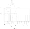
FIG. 2 is a schematic plan view of a data center cooling system provided by an example embodiment of the present disclosure; -
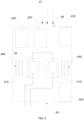
FIG. 3 is a schematic view of the connection between the cooling tower and the first heat exchanger, the second heat exchanger, the server in the data center cooling system provided by an example embodiment of the present disclosure; -
FIG. 4 is a schematic view of the arrangement position between a plurality of cabinets and an air returning channel in a data center cooling system provided by an example embodiment of the present disclosure; -
FIG. 5 is an internal schematic view of a server of a data center cooling system provided by an example embodiment of the present disclosure, in which the direction pointed by the arrow is the flow direction of the air flow; -
FIG. 6 is a schematic view of the cooperation between the first heat exchanger and the fan of the data center cooling system provided by an example embodiment of the present disclosure. - 1-machine room; 10-cooling tower; 20-air cooling unit; 21-first heat exchanger; 22-fan; 23-air returning channel; 30-liquid cooling unit; 31-second heat exchanger; 40-cabinet; 41- server; 410-central processing unit; 420-hard disk drive; 430-network interface controller; 440-dual inline memory module; 450-power supply; 46-water segregator; 460-water segregating pipe; 461-first water incoming port; 462- first water outcoming port; 47-water collector; 470-water collecting pipe; 471-second water incoming port; 472-second water outcoming port; 48-air inlet of the server; 49-air outlet of the server; 50-cold plate; 60-first space; 70-second space; 80-first water pump; 90-second water pump; 95-first switching valve; 96-second switching valve; 100-air outcoming hole.
- Detailed description of the present disclosure will be described in detail below with reference to the accompanying drawings. It should be understood that the detailed description described here is only used to illustrate and explain the present disclosure, and is not used to limit the present disclosure.
- In the present disclosure, unless otherwise stated, "connection" may be a direct connection or an indirect connection, "inside and outside" refers to the inside and outside of the corresponding structure or component outline; "far and near" refers to far from or near to the corresponding structure or component.
- With the high-density integration of IT equipment of an electronic information system machine room, the phenomenon of increasing equipment heat dissipation and machine room heat dissipation has begun to attract strong attention from all walks of life. According to research, IT/telecommunications-related carbon emissions have become one of the largest sources of greenhouse gas emissions, resulting in 860 million tons of carbon emissions per year, and the emission momentum in this field is still growing rapidly with the growing global demand for computing, data storage, and communication technologies. Even if people vigorously improve the energy efficiency of equipment, machine rooms and other devices and data centers, global IT-related carbon emissions will reach 1.54 billion tons by 2020. Therefore, more and more people are paying attention to the construction of green machine rooms.
- PUE (Power Usage Effectiveness) value has become an internationally accepted measure of data center power usage efficiency. The PUE value is the ratio of all energy consumed by the data center to the energy consumed by the IT loads. The closer the PUE value is to 1, the higher the greenness of a data center. Currently, the PUE value of most data centers is between 2-3. Therefore, how to reduce the PUE value of the data center and reduce the carbon emissions related to the data center is crucial.
- In view of this, according to a first aspect of the present disclosure, a data center cooling system is provided. Referring to
FIGS. 1-6 , the data center cooling system includes acooling tower 10, anair cooling unit 20, aliquid cooling unit 30 and acabinet 40. Theair cooling unit 20 includes afirst heat exchanger 21, afan 22 and anair returning channel 23. Theliquid cooling unit 30 includes asecond heat exchanger 31, and thecabinet 40 includes aserver 41. - A coolant outlet of the
cooling tower 10 is connected to a coolant inlet of thefirst heat exchanger 21 and a first coolant inlet of thesecond heat exchanger 31. A coolant outlet offirst heat exchanger 21 and a first coolant outlet of thesecond heat exchanger 31 are connected to a coolant inlet of coolingtower 10. A second coolant outlet of thesecond heat exchanger 31 is connected to a coolant inlet of theserver 41, and a coolant outlet of theserver 41 is connected to a second coolant inlet of thesecond heat exchanger 31. That is, thefirst heat exchanger 21 and thesecond heat exchanger 31 are connected in parallel with each other. An air inlet of theair returning channel 23 is connected to anair outlet 49 of theserver 41 and is used to transport the air flowing out of theair outlet 49 of theserver 41 to thefirst heat exchanger 21. Thefan 22 is used to cause the air flowing out of the air outlet of theair returning channel 23 flow to theserver 41 after passing through thefirst heat exchanger 21, so that the air flowing through thefirst heat exchanger 21 can enter theserver 41 through theair inlet 48 of theserver 41. - During the cooling process of the
server 41, a portion of the coolant at a lower temperature flowing out of the coolant outlet of thecooling tower 10 flows into thefirst heat exchanger 21, and the other portion flows into thesecond heat exchanger 31. When thefan 22 is running, the hot air flowing out of the air outlet of the air returning channel 12 and absorbing heat in theserver 41 flows through thefirst heat exchanger 21 and exchanges heat with the coolant in thefirst heat exchanger 21, so that the temperature of the hot air that absorbs heat in theserver 41 is reduced. The air at the reduced temperature blows into theserver 41 and continues to cool theserver 41, achieving air cooling of theserver 41. The coolant at a higher temperature after absorbing the heat of theserver 41 flows out of the coolant outlet of theserver 41 and flows into thesecond heat exchanger 31 through the second coolant inlet of thesecond heat exchanger 31. In thesecond heat exchanger 31, the coolant at the higher temperature after absorbing the heat of theserver 41 exchange heat with the coolant at the lower temperature flowing out of thecooling tower 10, so that the coolant at the lower temperature flows out of the second coolant outlet of thesecond heat exchanger 31. The coolant flows to theserver 41 to absorb the heat of theserver 41. The heat-absorbed coolant flowing out of the coolant outlet of thefirst heat exchanger 21 and the first coolant outlet of thesecond heat exchanger 31 finally returns to thecooling tower 10 and discharges the heat to the atmosphere. - With the above technical solution, the data center cooling system provided by the present disclosure discharges the heat of the
server 41 into the atmosphere through thecooling tower 10. In other words, the cooling capacity for both liquid cooling and air cooling of theserver 41 comes from thecooling tower 10. According to statistical data, the cooling of existing data centers accounts for about 40% of the total power consumption of amachine room 1, and the use of air-conditioning cooling units is one of the important factors leading to an increase in total cooling power consumption. Comparing the data center cooling system provided by the present disclosure with the existing technical solutions that provide cooling capacity through a plurality of devices (such as a compressor, an expansion valve, an evaporator, a condenser) in the air-conditioning cooling unit, the data center cooling system provided by the present disclosure does not require the use of air-conditioning cooling unit, so that the energy consumption required for cooling the server of the present disclosure is lower, which is conducive to reducing the total energy consumption of the data center, thereby reducing the PUE of the data center, thereby reducing carbon emissions, and helping to achieve targets of "peak carbon dioxide emissions and carbon neutrality." - Moreover, since the data center cooling system provided by the present disclosure is not cooled by the air-conditioning cooling unit, that is, Freon is not used as a refrigerant. On one hand, it is possible to avoid the leakage of Freon which may pollute the environment. On the other hand, it is also possible to avoid fluoride emissions. Since fluorine-containing gas is also a greenhouse gas, it avoids the emission of fluorine-containing gas from increasing the greenhouse effect.
- In addition, compared with the existing technical solution of cooling the data center through liquid cooling combined with air conditioning supplementary cooling, the data center cooling system provided by the present disclosure has a simpler architecture and therefore has higher reliability, and the cost is lower, and when deploying a data center, it can achieve rapid deployment of the data center. Moreover, since the cooling temperature of the
cooling tower 10 is related to the wet-bulb temperature of the environment where thecooling tower 10 is located, rather than the dry-bulb temperature (i.e., ambient temperature) of the environment where thecooling tower 10 is located, the wet-bulb temperature in most parts of the world can meet the requirements for the temperature of the coolant flowing out of the coolant outlet of thecooling tower 10. Therefore, the data center cooling system provided by the present disclosure is not easily restricted by the regional ambient temperature and can be applied to most regions around the world. - Through the data center cooling system provided by the present disclosure, the
server 41 can be liquid-cooled with the coolant of 35°C-40°C, and at the same time, thefan 22 andfirst heat exchanger 21 can be used to transport air of 35°C-40°C to theserver 41 for air cooling. The temperature of the heat-exchanged air flowing out of theair outlet 49 of theserver 41 is about 40°C-45°C, achieving "large air volume and small temperature difference" heat dissipation for theserver 41. - Optionally, the number of the
first heat exchanger 21, thesecond heat exchanger 31 and thefan 22 described above may be one or multiple, which is not limited in the present disclosure. - Optionally, the
cooling tower 10 described above can be an open cooling tower, a closed cooling tower, a natural ventilation cooling tower, a mechanical ventilation cooling tower, a mixed ventilation cooling tower, a wet cooling tower, a dry cooling tower, a wet and dry cooling tower, etc., The present disclosure does not limit the specific type, quantity, size, shape, etc. of thecooling tower 10. - As an implementation manner, as shown in
FIG. 5 , the above-mentionedserver 41 includes a central processing unit 410 (CPU), a hard disk drive 420 (HDD), a network interface controller 430 (NIC), and a dual inline memory module 440 (DIMM) and a power supply 450 (Power supply unit, PSU). Thecentral processing unit 410 is provided with acold plate 50. The second coolant outlet of thesecond heat exchanger 31 is connected to the coolant inlet of thecold plate 50. The coolant outlet of thecold plate 50 is connected to the second coolant inlet of thesecond heat exchanger 31. The coolant inlet ofcold plate 50 is the coolant inlet of theserver 41, and the coolant outlet ofcold plate 50 is the coolant outlet of theserver 41. Thecentral processing unit 410, thehard disk drive 420, thenetwork interface controller 430, the dualinline memory module 440 and thepower supply 450 are all arranged between theair inlet 48 of theserver 41 and theair outlet 49 of theserver 41. - During the cooling process of the
server 41 by the data center cooling system, the coolant in thesecond heat exchanger 31 enters thecold plate 50 through the second coolant outlet and the coolant inlet of thecold plate 50. The coolant in thecold plate 50 is performing heat exchange with thecentral processing unit 410, absorbing the heat of thecentral processing unit 410 to achieve liquid cooling of thecentral processing unit 410. The coolant flowing out of the coolant outlet of thecold plate 50 can perform heat exchange with the coolant flowing from thecooling tower 10 to thesecond heat exchanger 31, thereby bringing the heat of thecentral processing unit 410 to thecooling tower 10 and releasing the heat into the atmosphere. Since thecentral processing unit 410, thehard disk drive 420, thenetwork interface controller 430, the dualinline memory module 440 and thepower supply 450 are all mounted between theair inlet 48 of theserver 41 and theair outlet 49 of theserver 41, during the process of thefan 22 blowing the air at a lower temperature flowing through thefirst heat exchanger 21 to the interior of the data center, the air flows in from theair inlet 48 of theserver 41 and out from theair outlet 49 of theserver 41. As the air flows inside theserver 41, it can take away the heat from thecentral processing unit 410, thehard disk drive 420, thenetwork interface controller 430, the dualinline memory module 440 and thepower supply 450, achieving the cooling of thecentral processing unit 410, thehard disk drive 420, thenetwork interface controller 430, the dualinline memory module 440 and thepower supply 450. - Here, in the data center cooling system provided by the present disclosure, the
central processing unit 410 is liquid-cooled through thecold plate 50, which can effectively reduce the temperature of thecentral processing unit 410 first, avoiding the internal temperature of theserver 41 to be too high during the process of the air flowing from theair inlet 48 of theserver 41 to theair outlet 49 of theserver 41 to bring out the heat of thecentral processing unit 410, which reversely heats thehard disk drive 420, thenetwork interface controller 430, the dualinline memory module 440 and thepower supply 450, or affects the heat dissipation of the air insideserver 41 on thehard disk drive 420, thenetwork interface controller 430, the dualinline memory module 440 and thepower supply 450, ensuring the cooling effect and cooling efficiency. - Optionally, in an embodiment provided by the present disclosure, as shown in
FIG. 5 , theair inlet 48 of theserver 41 may be arranged opposite to theair outlet 49 of the server 4, thehard disk drive 420 and thenetwork interface controller 430 are both arranged close to theair inlet 48 of theserver 41, and thepower supply 450 is arranged close to theair outlet 49 of theserver 41, and thecentral processing unit 410 and the dualinline memory module 440 are located between both thehard disk drive 420 and thenetwork interface controller 430 and thepower supply 450. Since thehard disk drive 420 and thenetwork interface controller 430 have a weak ability to withstand temperature, and the temperature of the air at theair inlet 48 of theserver 41 is low, thehard disk drive 420 and thenetwork interface controller 430 are arranged close to theair inlet 48 of theserver 41 to ensure the cooling of thehard disk drive 420 and thenetwork interface controller 430, and thepower supply 450 has a strong ability to withstand medium or high temperatures, so thepower supply 450 is arranged close to theair outlet 49 of theserver 41. - With the above arrangement, after the air enters the
server 41 from theair inlet 48 of theserver 41, it will blow through thehard disk drive 420, thenetwork interface controller 430, the dualinline memory module 440, thecentral processing unit 410 and thepower supply 450 in sequence, and then flow out of theair outlet 49 of theserver 41, such that the cooling needs of thehard disk drive 420, thenetwork interface controller 430, the dualinline memory module 440, thecentral processing unit 410 and thepower supply 450 inside theserver 41 can be met. - Here, as shown in
FIG. 5 , both thecentral processing unit 410 and thecold plate 50 are multiple. The multiplecold plates 50 and the multiplecentral processing units 410 are arranged in one-to-one correspondence. The multiplecold plates 50 may be connected in series or in parallel with each other. - For embodiments with of the multiple
cold plates 50 connected in series have the advantages of simple structural components and easy to ensure that the flow rate of the coolant in eachcold plate 50 is approximately the same. During the cooling process of the multiplecold plates 50 by theliquid cooling unit 30, the coolant flowing out of the second coolant outlet of thesecond heat exchanger 31 can first enter a firstcold plate 50, and then flow to the nextcold plate 50 in sequence, and finally flow out of the coolant outlet of the lastcold plate 50. Here, it should be noted that in order to prevent the temperature of the coolant from rising after absorbing the heat of the upstreamcentral processing unit 410 and affecting the absorption of heat from the nextcentral processing unit 410, in the present disclosure, the temperature difference between the coolant between adjacentcold plates 50 can be reduced by increasing the flow rate of the coolant from thesecond heat exchanger 31 to thecold plate 50, so that eachcentral processing unit 410 can obtain better cooling effect. - For embodiments with the multiple
cold plates 50 connected in parallel, the coolant with lower temperature can flow through differentcold plates 50 respectively. The coolant will not be interfered by the heat exchange of the adjacentcentral processing unit 410 during the flow process, and, because the coolant in differentcold plates 50 is independent of each other, precise control of the heat dissipation of the multiplecentral processing units 410 can be achieved by controlling the flow of coolant flowing through differentcold plates 50. - Optionally, in the present disclosure, as shown in
FIG. 3 , in order to improve the integration of the data center, thecabinet 40 may include a plurality ofservers 41. Thecabinet 40 may also include awater segregator 46 and awater collector 47. Thewater segregator 46 includes awater segregating pipe 460, a first waterincoming port 461 and a firstwater outcoming port 462 arranged on thewater segregating pipe 460. The firstwater outcoming port 462 is multiple. Thewater collector 47 includes awater collecting pipe 470, a second waterincoming port 471 and a secondwater outcoming port 472 arranged on thewater collecting pipe 470. The second waterincoming port 471 is multiple. The second coolant outlet of thesecond heat exchanger 31 is connected to the first waterincoming port 461. Each firstwater outcoming port 462 is connected to the coolant inlet of the correspondingserver 41. Each second waterincoming port 471 is connected to the coolant outlet of the correspondingserver 41. The secondwater outcoming port 472 is connected to the second coolant inlet of thesecond heat exchanger 31. - In other words, during the cooling and heat dissipation process of the
server 41, the coolant enters thewater segregating pipe 460 through the second coolant outlet of thesecond heat exchanger 31 and the first waterincoming port 461 of thewater segregator 46. Thewater segregating pipe 460 is provided with the firstwater outcoming port 462 connected to the coolant inlet of the correspondingserver 41. In this way, the coolant entering thewater segregator 46 enters the correspondingserver 41 through the firstwater outcoming port 462. After absorbing the heat of theserver 41, the coolant flows into the collectingpipe 470 through the second waterincoming port 471 of thewater collector 47. Subsequently, the high-temperature coolant flowing into thewater collecting pipe 470 exchanges heat with the low-temperature coolant flowing out of thecooling tower 10, and then becomes low-temperature coolant again and flows into thewater segregator 46. In this cycle, a continuous cooling and heat dissipation of themultiple servers 41 can be implemented. - In the present disclosure, since the coolant directly flows from the second coolant outlet of the
second heat exchanger 31 into thecold plate 50 provided on thecentral processing unit 410, thecentral processing unit 410, as a core component of theserver 41, has high requirements for the cleanliness of the coolant. Optionally, the second coolant outlet of thesecond heat exchanger 31 may be provided with at least one of a filtering device, a sterilization device, and a descaling device. By setting the filtering device, the sterilization device, and the descaling device at the second coolant outlet of thesecond heat exchanger 31, the cleanliness of the coolant circulating in thecold plate 50 can be improved, avoiding or reducing the clogging and poor flow of the coolant in the cold plate, further improving the cooling efficiency and effect of thecentral processing unit 410. - Optionally, the
cabinet 40 may be multiple, and theservers 41 in themultiple cabinets 40 are connected in parallel with each other, so that the coolant flowing out of the second coolant outlet of thesecond heat exchanger 31 can be divided into a plurality of streams and flow to theservers 41 indifferent cabinets 40. - For the case where the
cabinet 40 is multiple, as shown inFIG. 4 , theair outlet 49 of theserver 41 of onecabinet 40 can be arranged opposite to theair outlet 49 of theserver 41 of anothercabinet 40, and theair outlets 49 of the twoservers 41 are located between theair inlets 48 of the twoservers 41, thereby facilitating the arrangement of theair returning channel 23. - Optionally, the
air cooling unit 20 may further include a mounting structure on which an air incoming hole and an airoutcoming hole 100 are formed. Thefirst heat exchanger 21 and thefan 22 are mounted on the mounting structure and located between the air incoming hole and the airoutcoming hole 100. In an embodiment provided by the present disclosure, the air outlet of theair returning channel 23 is connected to the air incoming hole. In this way, the hot air flowing out of the air outlet of theair returning channel 23 and absorbing the heat of theserver 41 can flow to thefirst heat exchanger 21 through the air incoming hole of the mounting structure. After the air flow that has absorbed the heat of theserver 41 is cooled by thefirst heat exchanger 21, theFan 22 re-blows the air flow that has been dissipated byfirst heat exchanger 21 to theserver 41 through the air outcoming hole of the mounting structure, circulating in this manner. Since the air outlet of theair returning channel 23 is connected to the air incoming hole, it can be ensured that all the air that has absorbed the heat of theserver 41 flows through thefirst heat exchanger 21 for heat exchange. - In another embodiment provided by the present disclosure, as shown in
FIGS. 1-2 , the mounting structure is adapted to be arranged in themachine room 1, and to separate the interior of themachine room 1 into afirst space 60 and asecond space 70. The air incoming hole is located on a side of the mounting structure close to thefirst space 60, and the airoutcoming hole 100 is located on a side of the mounting structure close to thesecond space 70. Theserver 41 is arranged within thesecond space 70, and the air outlet of theair returning channel 23 is in communication with thefirst space 60. The hot air flowing out of the air outlet of theair returning channel 23 and absorbing the heat of theserver 41 can flow intofirst space 60. Since thefirst space 60 and thesecond space 70 are separated by the mounting structure, the hot air infirst space 60 will not flow into thesecond space 70 and cause the temperature of the server in thesecond space 70 to be increased, and the hot air infirst space 60 can flow throughfirst heat exchanger 21 for heat exchange under the action of thefan 22. - The difference between the above two embodiments is that when the air outlet of the
air returning channel 23 is connected to the air incoming hole of the mounting structure, the mounting structure may not isolate the internal space ofmachine room 1, but when the mounting structure isolates the internal space ofmachine room 1, the air outlet of theair returning channel 23 can be or be not connected to the air incoming hole of the mounting structure. - Optionally, the
fan 22 can be arranged close to the air incoming hole of the mounting structure, or can be arranged close to the airoutcoming hole 100 of the mounting structure, which is not limited in the present disclosure. - Optionally, in order to prevent the airflow entraining dust and other impurities from entering the
server 41, in the present disclosure, theair cooling unit 20 also includes an air filtering mesh arranged at the air incoming hole. The air filtering mesh can filter the air flow before entering the data center and prevent dust carried in the air flow from entering the interior of theserver 41 to ensure the operating environment of theserver 41. - Optionally, as shown in
FIGS. 1 and2 , the data center cooling system also includes afirst water pump 80 and asecond water pump 90. Thefirst water pump 80 is used to pump the coolant flowing out of the coolant outlet of thecooling tower 10 to thefirst heat exchanger 21 and thesecond heat exchanger 31. Thesecond water pump 90 are used to pump the coolant flowing out of the second coolant outlet of thesecond heat exchanger 31 to theserver 41. Thefirst water pump 80 can provide driving force for the flow of coolant in thefirst heat exchanger 21, and thesecond water pump 90 can provide driving force for the flow of the coolant in thesecond heat exchanger 31, so that the coolant can continuously circulate in thefirst heat exchanger 21 and thesecond heat exchanger 31, achieving uninterrupted cooling and heat dissipation of the data center. Here, the rotation speed offirst water pump 80 andsecond water pump 90 may be adjusted to match the cooling and heat dissipation needs of theserver 41. Specifically, when the heat dissipation needs of theserver 41 increase, the rotation speed offirst water pump 80 andsecond water pump 90 may be increased accordingly, so that a larger amount of coolant can exchange heat with theserver 41 per unit time, improving the heat exchange efficiency withserver 41; when the heat dissipation needs of the data center decreases, the rotation speed of thefirst water pump 80 andsecond water pump 90 can be lowered accordingly. The rotation speed can meet the heat dissipation needs of theserver 41 while reducing the energy consumption of thefirst water pump 80 and thesecond water pump 90. - Optionally, the data center cooling system also includes a
first switching valve 95 and asecond switching valve 96, as shown inFIGS. 1-2 . Thefirst switching valve 95 is arranged at the coolant outlet of thefirst heat exchanger 21 and/or the first coolant outlet of thesecond heat exchanger 31, thesecond switching valve 96 is arranged at the coolant inlet of theserver 41. Since thefirst switching valve 95 is arranged at the coolant outlet of thefirst heat exchanger 21 and/or the first coolant outlet of thesecond heat exchanger 31, thefirst heat exchanger 21 and thesecond heat exchanger 31 can operate simultaneously or independently. Take the embodiments with thefirst switching valve 95 being provided at the first coolant outlet of thesecond heat exchanger 31 as an example. When thefirst switching valve 95 is closed, the coolant flowing out of the coolant outlet of thecooling tower 10 will no longer flow into thesecond heat exchanger 31 continuously, but only continuously flows into thefirst heat exchanger 21, so that the continuous air cooling of theserver 41 can be achieved only through theair cooling unit 20, without the continuous liquid cooling of theserver 41 through theliquid cooling unit 30. In this way, the cooling manner of theserver 41 can be selected based on the current temperature of theserver 41, which is more beneficial to reduce the energy consumption of data center cooling system. Since thesecond switching valve 96 is provided at the coolant inlet of theserver 41, the coolant entering theserver 41 can be conducted and cut off by opening or closing thesecond switching valve 96. For embodiments with a plurality ofservers 41, the coolant can be allowed to enter theserver 41 that need to dissipate heat, avoiding the coolant flowing through theserver 41 that does not need to dissipate heat, causing the cooling capacity of the coolant to not be effectively utilized. - In order to further reduce the cost of the data center cooling system, the coolant mentioned above can be water. Water is cheap, easy to supply, and will not cause pollution to the atmospheric environment during the heat exchange process.
- According to a second aspect of the present disclosure, a data center is provided, including the data center cooling system described above. The data center has all the technical effects of the data center cooling system described above, which will not be described in detail here.
- The preferred embodiments of the present disclosure have been described in detail above with reference to the accompanying drawings. However, the present disclosure is not limited to the specific details of the above-mentioned embodiments. Within the scope of the technical concept of the present disclosure, various simple modifications can be made to the technical solutions of the present disclosure. These simple modifications all belong to the protection scope of the present disclosure.
- In addition, it should be noted that each of the specific technical features described in the above detailed description can be combined in any suitable way if there is no contradiction. In order to avoid unnecessary repetition, the present disclosure discusses various possible combinations. The method will not be further explained.
- In addition, any combination of various embodiments of the present disclosure can also be carried out, and as long as they do not violate the idea of the present disclosure, they should also be regarded as the contents disclosed in the present disclosure.
Claims (11)
- A data center cooling system, comprising a cooling tower (10), an air cooling unit (20), a liquid cooling unit (30) and a cabinet (40), the air cooling unit (20) comprising a first heat exchanger (21), a fan (22) and an air returning channel (23), the liquid cooling unit (30) comprising a second heat exchanger (31), the cabinet (40) comprising a server (41);a coolant outlet of the cooling tower (10) is connected to a coolant inlet of the first heat exchanger (21) and a first coolant inlet of the second heat exchanger (31), a coolant outlet of the first heat exchanger (21) and a first coolant outlet of the second heat exchanger (31) are connected to a coolant inlet of the cooling tower (10), a second coolant outlet of the second heat exchanger (31) is connected to a coolant inlet of the server (41), and a coolant outlet of the server (41) is connected to a second coolant inlet of the second heat exchanger (31);an air inlet of the air returning channel (23) is connected to an air outlet (49) of the server (41) and is configured to transport air flowing out of the air outlet (49) of the server (41) to the first heat exchanger (21), the fan (22) is configured to cause the air flowing out of an air outlet of the air returning channel (23) to flow to the server (41) after flowing through the first heat exchanger (21), so that the air flow through the first heat exchanger (21) can enter the server (41) through an air inlet (48) of the server (41).
- The data center cooling system of claim 1, wherein the server (41) comprises a central processing unit (410), a hard disk drive (420), a network interface controller (430), a dual inline memory module (440) and a power supply (450);the central processing unit (410) is provided with a cold plate (50), the second coolant outlet of the second heat exchanger (31) is connected to a coolant inlet of the cold plate (50), a coolant outlet of the cold plate (50) is connected to the second coolant inlet of the second heat exchanger (31), the coolant inlet of the cold plate (50) is the coolant inlet of the server (41), the coolant outlet of the cold plate (50) is the coolant outlet of the server (41);the central processing unit (410), the hard disk drive (420), the network interface controller (430), the dual inline memory module (440) and the power supply (450) are all arranged between the air inlet (48) of the server (41) and the air outlet (49) of the server (41).
- The data center cooling system of claim 2, wherein the air inlet (48) of the server (41) is arranged opposite to the air outlet (49) of the server (41), the hard disk drive (420) and the network interface controller (430) are arranged close to the air inlet (48) of the server (41), the power supply (450) is arranged close to the air outlet (49) of the server (41), and the central processing unit (410) and the dual inline memory module (440) are located between both the hard disk drive (420) and the network interface controller (430) and the power supply (450).
- The data center cooling system of claim 2, wherein both the central processing unit (410) and the cold plate (50) are multiple, the multiple cold plates (50) and the multiple central processing units (410) are arranged in one-to-one correspondence, and the multiple cold plates (50) are connected in series or in parallel with each other.
- The data center cooling system of any of claims 1-4, wherein the cabinet (40) comprises a plurality of servers (41), the cabinet (40) further comprises a water segregator (46) and a water collector (47), the water segregator (46) comprises a water segregating pipe (460), a first water incoming port (461) and a first water outcoming port (462) arranged on the water segregating pipe (460), the first water outcoming port (462) is multiple, and the water collector (47) comprises a water collecting pipe (470), a second water incoming port (471) and a second water outcoming port (472) arranged on the water collecting pipe (470), the second water incoming port (471) is multiple;
the second coolant outlet of the second heat exchanger (31) is connected to the first water incoming port (461), each first water outcoming port (462) is connected to the coolant inlet of the corresponding server (41), each second water incoming port (471) is connected to the coolant outlet of the corresponding server (41), and the second water outcoming port (472) is connected to the second coolant inlet of the second heat exchanger (31). - The data center cooling system of any of claims 1-4, wherein at least one of a filtering device, a sterilization device, and a descaling device is provided at the second coolant outlet of the second heat exchanger (31).
- The data center cooling system of claim 1, wherein the air cooling unit (20) further comprises a mounting structure on which an air incoming hole and an air outcoming hole (100) are formed, and the first heat exchanger (21) and the fan (22) are mounted on the mounting structure and are located between the air incoming hole and the air outcoming hole (100);
wherein the air outlet of the air returning channel (23) is connected to the air incoming hole; or, the mounting structure is configured to be arranged in a machine room (1), and to separate the interior of the machine room (1) into a first space (60) and a second space (70), the air incoming hole is located on a side of the mounting structure close to the first space (60), and the air outcoming hole (100) is located on a side of the mounting structure close to the second space (70), the server (41) is arranged within the second space (70), and the air outlet of the air returning channel (23) is in communication with the first space (60). - The data center cooling system of claim 7, wherein the air cooling unit (20) further comprises an air filtering mesh arranged at the air incoming hole.
- The data center cooling system of any of claims 1-4 or 7-8, wherein the data center cooling system further comprises a first water pump (80) and a second water pump (90), the first water pump (80) is configured to pump the coolant flowing out of the coolant outlet of the cooling tower (10) to the first heat exchanger (21) and the second heat exchanger (31), and the water pump (90) is configured to pump the coolant flowing out of the second coolant outlet of the second heat exchanger (31) to the server (41).
- The data center cooling system of any of claims 1-4 or 7-8, wherein the data center cooling system further comprises a first switching valve (95) and a second switching valve (96), the first switching valve (95) is arranged at the coolant outlet of the first heat exchanger (21) and/or the first coolant outlet of the second heat exchanger (31), and the second switching valve (96) is arranged at the coolant inlet of the server (41).
- A data center, comprising the data center cooling system of any of claims 1-10.
Applications Claiming Priority (2)
| Application Number | Priority Date | Filing Date | Title |
|---|---|---|---|
| CN202111658729.4A CN114269129A (en) | 2021-12-30 | 2021-12-30 | Data center cooling system and data center |
| PCT/CN2022/138713 WO2023124976A1 (en) | 2021-12-30 | 2022-12-13 | Data center cooling system and data center |
Publications (2)
| Publication Number | Publication Date |
|---|---|
| EP4440267A1 true EP4440267A1 (en) | 2024-10-02 |
| EP4440267A4 EP4440267A4 (en) | 2025-04-02 |
Family
ID=80832031
Family Applications (1)
| Application Number | Title | Priority Date | Filing Date |
|---|---|---|---|
| EP22914231.0A Pending EP4440267A4 (en) | 2021-12-30 | 2022-12-13 | COOLING SYSTEM FOR DATA CENTER AND DATA CENTER |
Country Status (4)
| Country | Link |
|---|---|
| US (1) | US12328850B2 (en) |
| EP (1) | EP4440267A4 (en) |
| CN (1) | CN114269129A (en) |
| WO (1) | WO2023124976A1 (en) |
Families Citing this family (16)
| Publication number | Priority date | Publication date | Assignee | Title |
|---|---|---|---|---|
| CN114269129A (en) * | 2021-12-30 | 2022-04-01 | 北京字节跳动网络技术有限公司 | Data center cooling system and data center |
| CN115038299B (en) * | 2022-06-02 | 2025-05-27 | 上海威固信息技术股份有限公司 | A data center cooling system and control method thereof |
| CN115226375B (en) | 2022-07-13 | 2024-06-04 | 北京有竹居网络技术有限公司 | Cooling system |
| CN115151110A (en) * | 2022-07-20 | 2022-10-04 | 阿里巴巴(中国)有限公司 | Liquid cooling data center test equipment and liquid cooling data center test system |
| CN117560889B (en) * | 2022-08-03 | 2026-03-20 | 超聚变数字技术股份有限公司 | Cooling medium distribution device, heat dissipation cabinet and server system |
| CN115406689B (en) * | 2022-08-08 | 2024-06-18 | 国网浙江省电力有限公司杭州供电公司 | A data center testing device based on fake load simulation server operation |
| CN218514728U (en) * | 2022-08-16 | 2023-02-21 | 北京比特大陆科技有限公司 | Cooling Integrated System |
| JP2025006986A (en) * | 2023-06-30 | 2025-01-17 | ニデック株式会社 | system |
| CN116583092B (en) * | 2023-07-10 | 2023-09-08 | 深圳安森德半导体有限公司 | High-temperature protection equipment of DCDC voltage stabilizer |
| CN117202636A (en) * | 2023-09-25 | 2023-12-08 | 扬州智能科技有限公司 | A control system for computer room air conditioners |
| CN117424115B (en) * | 2023-10-28 | 2024-04-19 | 浙江诺电电力科技有限公司 | High-voltage switch station convenient for heat dissipation |
| CN117560910A (en) * | 2023-12-06 | 2024-02-13 | 中创美纵信息科技(重庆)有限公司 | Cold plate liquid cooling fully loaded cabinet cooling system with backplane |
| CN117596845A (en) * | 2023-12-06 | 2024-02-23 | 中创美纵信息科技(重庆)有限公司 | Refrigeration system of heat pipe refrigeration integrated cabinet |
| CN121038211A (en) * | 2024-05-27 | 2025-11-28 | 华为云计算技术有限公司 | A liquid-cooled data center |
| CN119136493A (en) * | 2024-09-10 | 2024-12-13 | 抖音视界有限公司 | Cooling systems and data centers |
| CN118829176B (en) * | 2024-09-18 | 2024-12-31 | 腾讯科技(深圳)有限公司 | Cooling system, control method, device and equipment of cooling system and storage medium |
Family Cites Families (21)
| Publication number | Priority date | Publication date | Assignee | Title |
|---|---|---|---|---|
| CA3013470C (en) * | 2010-06-23 | 2021-04-13 | Inertech Ip Llc | Space-saving high-density modular data center and an energy-efficient cooling system |
| TWI445493B (en) * | 2011-11-11 | 2014-07-11 | Inventec Corp | Heat dissipation system |
| US9043035B2 (en) * | 2011-11-29 | 2015-05-26 | International Business Machines Corporation | Dynamically limiting energy consumed by cooling apparatus |
| CN103047723A (en) * | 2012-12-25 | 2013-04-17 | 北京百度网讯科技有限公司 | Cooling system for server in machine room |
| CN103206747B (en) * | 2013-02-27 | 2016-01-20 | 北京百度网讯科技有限公司 | For the cooling system of server in server room |
| CN104254232B (en) * | 2014-09-17 | 2017-02-15 | 中国移动通信集团广东有限公司 | Heat-pipe circulating type primary refrigerant loop server cabinet heat dissipation system |
| WO2019019151A1 (en) * | 2017-07-28 | 2019-01-31 | Baidu.Com Times Technology (Beijing) Co., Ltd. | A design of liquid cooling for electronic racks with liquid cooled it components in data centers |
| CN207652877U (en) | 2017-11-23 | 2018-07-24 | 维谛技术有限公司 | The cooling system of liquid cooling server |
| CN207751075U (en) * | 2018-01-16 | 2018-08-21 | 香江科技股份有限公司 | A kind of double low-temperature receiver dual systems dehumidifying constant temperature energy-saving air-conditioning systems of data center |
| CN108834366B (en) * | 2018-06-08 | 2023-10-27 | 贵州绿云科技有限公司 | Air conditioning system of data machine room |
| US11116114B2 (en) * | 2019-06-18 | 2021-09-07 | Baidu Usa Llc | Cooling system design for data centers |
| CN210519308U (en) * | 2019-08-07 | 2020-05-12 | 世源科技工程有限公司 | A data center plate-cooled liquid cooling system |
| US10912229B1 (en) * | 2019-08-15 | 2021-02-02 | Baidu Usa Llc | Cooling system for high density racks with multi-function heat exchangers |
| CN110958812B (en) * | 2019-12-05 | 2021-07-23 | 山东超越数控电子股份有限公司 | Liquid cooling and air cooling combined cooling cabinet and cooling system |
| CN111031770B (en) * | 2020-01-15 | 2025-09-12 | 河南晶锐冷却技术股份有限公司 | Server cabinet and heat exchange equipment cabinet for server |
| US11297741B2 (en) * | 2020-05-26 | 2022-04-05 | Baidu Usa Llc | High resilient deployment based cooling system for electronic racks |
| US12029015B2 (en) * | 2020-12-23 | 2024-07-02 | Microsoft Technology Licensing, Llc | Control systems for air-assisted and liquid-cooled enclosures |
| CN113365477B (en) * | 2021-06-22 | 2023-02-03 | 北京百度网讯科技有限公司 | Cooling device, cabinet and data processing equipment |
| US11656665B2 (en) * | 2021-06-24 | 2023-05-23 | Nvidia Corporation | Hybrid cooling systems for datacenters |
| CN216626506U (en) * | 2021-12-30 | 2022-05-27 | 北京字节跳动网络技术有限公司 | Data center cooling system and data center |
| CN114269129A (en) * | 2021-12-30 | 2022-04-01 | 北京字节跳动网络技术有限公司 | Data center cooling system and data center |
-
2021
- 2021-12-30 CN CN202111658729.4A patent/CN114269129A/en active Pending
-
2022
- 2022-12-13 WO PCT/CN2022/138713 patent/WO2023124976A1/en not_active Ceased
- 2022-12-13 EP EP22914231.0A patent/EP4440267A4/en active Pending
-
2024
- 2024-06-28 US US18/759,113 patent/US12328850B2/en active Active
Also Published As
| Publication number | Publication date |
|---|---|
| EP4440267A4 (en) | 2025-04-02 |
| WO2023124976A1 (en) | 2023-07-06 |
| CN114269129A (en) | 2022-04-01 |
| US12328850B2 (en) | 2025-06-10 |
| US20240357772A1 (en) | 2024-10-24 |
Similar Documents
| Publication | Publication Date | Title |
|---|---|---|
| US12328850B2 (en) | Data center cooling system and data center | |
| Nadjahi et al. | A review of thermal management and innovative cooling strategies for data center | |
| US10356949B2 (en) | Server rack heat sink system with combination of liquid cooling device and auxiliary heat sink device | |
| US10401077B2 (en) | Chilled water cooling system | |
| CN216626506U (en) | Data center cooling system and data center | |
| CN110351986B (en) | Partitioned Internal Cooling Cabinet Cooling System with Compound Cooling Sources | |
| CN104699207A (en) | Server radiating system combining air-cooled naturally-cooled heat pipe air-conditioner with liquid-cooled device | |
| CN108444040A (en) | A kind of double low-temperature receiver data centers and temprature control method | |
| CN211953105U (en) | Cooling system | |
| CN102833988A (en) | Data center heat dissipation scheme | |
| CN211429864U (en) | A single-cabinet data center liquid cooling structure | |
| CN105135572A (en) | Heat pipe composite heat recovery type evaporative cooling air-conditioning system for data center | |
| CN221448921U (en) | Cooling system for air-liquid mixed cooling and miniature data center | |
| US20240349447A1 (en) | Cooling system, cabinet, and data center | |
| CN211406657U (en) | A heat pipe type backplane cooling device | |
| CN210425382U (en) | Outdoor unit with waste heat recovery and natural cold source utilization functions | |
| CN215872548U (en) | Heat management system of outdoor base station cabinet integrating storage battery compartment, equipment compartment and power supply compartment | |
| CN213367622U (en) | Frequency converter and refrigerating system | |
| CN101668409B (en) | Temperature control system and electronic equipment | |
| CN209768093U (en) | Liquid cooling system based on evaporative cooling technology | |
| CN202918627U (en) | Data center heat radiation device | |
| CN203518304U (en) | Power electronic device cooling system and distributed power generation system | |
| CN110602930A (en) | Data center machine room system | |
| CN216058077U (en) | A thermal management reformation system for communication base stations based on multiple cabinets | |
| JP2025522602A (en) | Cooling System |
Legal Events
| Date | Code | Title | Description |
|---|---|---|---|
| STAA | Information on the status of an ep patent application or granted ep patent |
Free format text: STATUS: THE INTERNATIONAL PUBLICATION HAS BEEN MADE |
|
| PUAI | Public reference made under article 153(3) epc to a published international application that has entered the european phase |
Free format text: ORIGINAL CODE: 0009012 |
|
| STAA | Information on the status of an ep patent application or granted ep patent |
Free format text: STATUS: REQUEST FOR EXAMINATION WAS MADE |
|
| 17P | Request for examination filed |
Effective date: 20240627 |
|
| AK | Designated contracting states |
Kind code of ref document: A1 Designated state(s): AL AT BE BG CH CY CZ DE DK EE ES FI FR GB GR HR HU IE IS IT LI LT LU LV MC ME MK MT NL NO PL PT RO RS SE SI SK SM TR |
|
| A4 | Supplementary search report drawn up and despatched |
Effective date: 20250305 |
|
| RIC1 | Information provided on ipc code assigned before grant |
Ipc: G06F 1/20 20060101ALI20250227BHEP Ipc: H05K 7/20 20060101AFI20250227BHEP |
|
| DAV | Request for validation of the european patent (deleted) | ||
| DAX | Request for extension of the european patent (deleted) |