EP4440265A1 - Heat dissipation assembly and control method and apparatus therefor, and heat dissipator and communication device - Google Patents
Heat dissipation assembly and control method and apparatus therefor, and heat dissipator and communication device Download PDFInfo
- Publication number
- EP4440265A1 EP4440265A1 EP22903400.4A EP22903400A EP4440265A1 EP 4440265 A1 EP4440265 A1 EP 4440265A1 EP 22903400 A EP22903400 A EP 22903400A EP 4440265 A1 EP4440265 A1 EP 4440265A1
- Authority
- EP
- European Patent Office
- Prior art keywords
- vibration plate
- heat dissipation
- dissipation assembly
- driving frequency
- piezoelectric sheet
- Prior art date
- Legal status (The legal status is an assumption and is not a legal conclusion. Google has not performed a legal analysis and makes no representation as to the accuracy of the status listed.)
- Pending
Links
- 230000017525 heat dissipation Effects 0.000 title claims abstract description 157
- 238000000034 method Methods 0.000 title claims abstract description 40
- 238000004891 communication Methods 0.000 title claims abstract description 18
- 238000003491 array Methods 0.000 claims description 30
- 230000004044 response Effects 0.000 claims description 4
- 238000010586 diagram Methods 0.000 description 13
- 230000001960 triggered effect Effects 0.000 description 8
- 230000000694 effects Effects 0.000 description 6
- 238000001816 cooling Methods 0.000 description 5
- 238000009434 installation Methods 0.000 description 3
- 239000000047 product Substances 0.000 description 3
- 238000009825 accumulation Methods 0.000 description 1
- 229910010293 ceramic material Inorganic materials 0.000 description 1
- 230000008602 contraction Effects 0.000 description 1
- 238000002788 crimping Methods 0.000 description 1
- 239000000428 dust Substances 0.000 description 1
- 239000013013 elastic material Substances 0.000 description 1
- 238000005265 energy consumption Methods 0.000 description 1
- 238000002474 experimental method Methods 0.000 description 1
- 239000012530 fluid Substances 0.000 description 1
- 239000004519 grease Substances 0.000 description 1
- 238000001746 injection moulding Methods 0.000 description 1
- 230000010354 integration Effects 0.000 description 1
- 230000007774 longterm Effects 0.000 description 1
- 239000000463 material Substances 0.000 description 1
- 230000010355 oscillation Effects 0.000 description 1
- 230000000737 periodic effect Effects 0.000 description 1
- 230000002035 prolonged effect Effects 0.000 description 1
- 238000010187 selection method Methods 0.000 description 1
- 239000013589 supplement Substances 0.000 description 1
- 230000003313 weakening effect Effects 0.000 description 1
Images




Classifications
-
- H—ELECTRICITY
- H05—ELECTRIC TECHNIQUES NOT OTHERWISE PROVIDED FOR
- H05K—PRINTED CIRCUITS; CASINGS OR CONSTRUCTIONAL DETAILS OF ELECTRIC APPARATUS; MANUFACTURE OF ASSEMBLAGES OF ELECTRICAL COMPONENTS
- H05K7/00—Constructional details common to different types of electric apparatus
- H05K7/20—Modifications to facilitate cooling, ventilating, or heating
- H05K7/20009—Modifications to facilitate cooling, ventilating, or heating using a gaseous coolant in electronic enclosures
- H05K7/20209—Thermal management, e.g. fan control
-
- B—PERFORMING OPERATIONS; TRANSPORTING
- B06—GENERATING OR TRANSMITTING MECHANICAL VIBRATIONS IN GENERAL
- B06B—METHODS OR APPARATUS FOR GENERATING OR TRANSMITTING MECHANICAL VIBRATIONS OF INFRASONIC, SONIC, OR ULTRASONIC FREQUENCY, e.g. FOR PERFORMING MECHANICAL WORK IN GENERAL
- B06B1/00—Methods or apparatus for generating mechanical vibrations of infrasonic, sonic, or ultrasonic frequency
- B06B1/02—Methods or apparatus for generating mechanical vibrations of infrasonic, sonic, or ultrasonic frequency making use of electrical energy
- B06B1/0207—Driving circuits
- B06B1/0223—Driving circuits for generating signals continuous in time
- B06B1/0238—Driving circuits for generating signals continuous in time of a single frequency, e.g. a sine-wave
- B06B1/0246—Driving circuits for generating signals continuous in time of a single frequency, e.g. a sine-wave with a feedback signal
- B06B1/0253—Driving circuits for generating signals continuous in time of a single frequency, e.g. a sine-wave with a feedback signal taken directly from the generator circuit
-
- H—ELECTRICITY
- H05—ELECTRIC TECHNIQUES NOT OTHERWISE PROVIDED FOR
- H05K—PRINTED CIRCUITS; CASINGS OR CONSTRUCTIONAL DETAILS OF ELECTRIC APPARATUS; MANUFACTURE OF ASSEMBLAGES OF ELECTRICAL COMPONENTS
- H05K7/00—Constructional details common to different types of electric apparatus
- H05K7/20—Modifications to facilitate cooling, ventilating, or heating
- H05K7/20009—Modifications to facilitate cooling, ventilating, or heating using a gaseous coolant in electronic enclosures
- H05K7/20136—Forced ventilation, e.g. by fans
- H05K7/20172—Fan mounting or fan specifications
-
- H—ELECTRICITY
- H01—ELECTRIC ELEMENTS
- H01Q—ANTENNAS, i.e. RADIO AERIALS
- H01Q1/00—Details of, or arrangements associated with, antennas
- H01Q1/02—Arrangements for de-icing; Arrangements for drying-out ; Arrangements for cooling; Arrangements for preventing corrosion
-
- H—ELECTRICITY
- H01—ELECTRIC ELEMENTS
- H01Q—ANTENNAS, i.e. RADIO AERIALS
- H01Q1/00—Details of, or arrangements associated with, antennas
- H01Q1/12—Supports; Mounting means
- H01Q1/22—Supports; Mounting means by structural association with other equipment or articles
- H01Q1/24—Supports; Mounting means by structural association with other equipment or articles with receiving set
- H01Q1/241—Supports; Mounting means by structural association with other equipment or articles with receiving set used in mobile communications, e.g. GSM
- H01Q1/246—Supports; Mounting means by structural association with other equipment or articles with receiving set used in mobile communications, e.g. GSM specially adapted for base stations
-
- H—ELECTRICITY
- H05—ELECTRIC TECHNIQUES NOT OTHERWISE PROVIDED FOR
- H05K—PRINTED CIRCUITS; CASINGS OR CONSTRUCTIONAL DETAILS OF ELECTRIC APPARATUS; MANUFACTURE OF ASSEMBLAGES OF ELECTRICAL COMPONENTS
- H05K7/00—Constructional details common to different types of electric apparatus
- H05K7/20—Modifications to facilitate cooling, ventilating, or heating
- H05K7/20009—Modifications to facilitate cooling, ventilating, or heating using a gaseous coolant in electronic enclosures
- H05K7/20136—Forced ventilation, e.g. by fans
-
- B—PERFORMING OPERATIONS; TRANSPORTING
- B06—GENERATING OR TRANSMITTING MECHANICAL VIBRATIONS IN GENERAL
- B06B—METHODS OR APPARATUS FOR GENERATING OR TRANSMITTING MECHANICAL VIBRATIONS OF INFRASONIC, SONIC, OR ULTRASONIC FREQUENCY, e.g. FOR PERFORMING MECHANICAL WORK IN GENERAL
- B06B1/00—Methods or apparatus for generating mechanical vibrations of infrasonic, sonic, or ultrasonic frequency
- B06B1/02—Methods or apparatus for generating mechanical vibrations of infrasonic, sonic, or ultrasonic frequency making use of electrical energy
- B06B1/0207—Driving circuits
- B06B1/0223—Driving circuits for generating signals continuous in time
- B06B1/0269—Driving circuits for generating signals continuous in time for generating multiple frequencies
- B06B1/0284—Driving circuits for generating signals continuous in time for generating multiple frequencies with consecutive, i.e. sequential generation, e.g. with frequency sweep
-
- B—PERFORMING OPERATIONS; TRANSPORTING
- B06—GENERATING OR TRANSMITTING MECHANICAL VIBRATIONS IN GENERAL
- B06B—METHODS OR APPARATUS FOR GENERATING OR TRANSMITTING MECHANICAL VIBRATIONS OF INFRASONIC, SONIC, OR ULTRASONIC FREQUENCY, e.g. FOR PERFORMING MECHANICAL WORK IN GENERAL
- B06B1/00—Methods or apparatus for generating mechanical vibrations of infrasonic, sonic, or ultrasonic frequency
- B06B1/02—Methods or apparatus for generating mechanical vibrations of infrasonic, sonic, or ultrasonic frequency making use of electrical energy
- B06B1/06—Methods or apparatus for generating mechanical vibrations of infrasonic, sonic, or ultrasonic frequency making use of electrical energy operating with piezoelectric effect or with electrostriction
- B06B1/0603—Methods or apparatus for generating mechanical vibrations of infrasonic, sonic, or ultrasonic frequency making use of electrical energy operating with piezoelectric effect or with electrostriction using a piezoelectric bender, e.g. bimorph
-
- B—PERFORMING OPERATIONS; TRANSPORTING
- B06—GENERATING OR TRANSMITTING MECHANICAL VIBRATIONS IN GENERAL
- B06B—METHODS OR APPARATUS FOR GENERATING OR TRANSMITTING MECHANICAL VIBRATIONS OF INFRASONIC, SONIC, OR ULTRASONIC FREQUENCY, e.g. FOR PERFORMING MECHANICAL WORK IN GENERAL
- B06B2201/00—Indexing scheme associated with B06B1/0207 for details covered by B06B1/0207 but not provided for in any of its subgroups
- B06B2201/20—Application to multi-element transducer
-
- B—PERFORMING OPERATIONS; TRANSPORTING
- B06—GENERATING OR TRANSMITTING MECHANICAL VIBRATIONS IN GENERAL
- B06B—METHODS OR APPARATUS FOR GENERATING OR TRANSMITTING MECHANICAL VIBRATIONS OF INFRASONIC, SONIC, OR ULTRASONIC FREQUENCY, e.g. FOR PERFORMING MECHANICAL WORK IN GENERAL
- B06B2201/00—Indexing scheme associated with B06B1/0207 for details covered by B06B1/0207 but not provided for in any of its subgroups
- B06B2201/40—Indexing scheme associated with B06B1/0207 for details covered by B06B1/0207 but not provided for in any of its subgroups with testing, calibrating, safety devices, built-in protection, construction details
-
- B—PERFORMING OPERATIONS; TRANSPORTING
- B06—GENERATING OR TRANSMITTING MECHANICAL VIBRATIONS IN GENERAL
- B06B—METHODS OR APPARATUS FOR GENERATING OR TRANSMITTING MECHANICAL VIBRATIONS OF INFRASONIC, SONIC, OR ULTRASONIC FREQUENCY, e.g. FOR PERFORMING MECHANICAL WORK IN GENERAL
- B06B2201/00—Indexing scheme associated with B06B1/0207 for details covered by B06B1/0207 but not provided for in any of its subgroups
- B06B2201/70—Specific application
-
- Y—GENERAL TAGGING OF NEW TECHNOLOGICAL DEVELOPMENTS; GENERAL TAGGING OF CROSS-SECTIONAL TECHNOLOGIES SPANNING OVER SEVERAL SECTIONS OF THE IPC; TECHNICAL SUBJECTS COVERED BY FORMER USPC CROSS-REFERENCE ART COLLECTIONS [XRACs] AND DIGESTS
- Y02—TECHNOLOGIES OR APPLICATIONS FOR MITIGATION OR ADAPTATION AGAINST CLIMATE CHANGE
- Y02D—CLIMATE CHANGE MITIGATION TECHNOLOGIES IN INFORMATION AND COMMUNICATION TECHNOLOGIES [ICT], I.E. INFORMATION AND COMMUNICATION TECHNOLOGIES AIMING AT THE REDUCTION OF THEIR OWN ENERGY USE
- Y02D10/00—Energy efficient computing, e.g. low power processors, power management or thermal management
Definitions
- the present disclosure relates to the technical field of electronic heat dissipation, and more particularly, to a heat dissipation assembly and a control method therefor, an apparatus, a heat dissipator, and a communication device.
- a piezoelectric vibration fan is suitable to forced air cooling of the RRU or the AAU of the outdoor communication base station due to its high reliability, low noise, low power consumption, high temperature resistance, and small installation space.
- the amplitude of the vibration plate is significantly reduced, greatly weakening its heat dissipation capability.
- the present disclosure proposes a heat dissipation assembly and a control method therefor, an apparatus, a heat dissipator, and a communication device.
- an embodiment provides a heat dissipation assembly, including a vibration plate unit and a drive unit, the vibration plate unit is provided with a vibration plate, and at least one piezoelectric sheet connected to the vibration plate, the drive unit is electrically connected to the vibration plate unit and is configured to: adjust, in response to meeting a trigger condition, a first driving frequency output to the piezoelectric sheet within a preset frequency range to obtain a plurality of corresponding first output currents, determine a target driving frequency based on the plurality of first output currents, and apply a driving voltage to the piezoelectric sheet based on the target driving frequency.
- an embodiment provides a heat dissipator, including the heat dissipation assembly described in the embodiment of the first aspect of the present disclosure.
- an embodiment provides a control method for a heat dissipation assembly, the heat dissipation assembly is provided with a vibration plate unit and a drive unit electrically connected to the vibration plate unit, and the vibration plate unit is provided with a vibration plate and at least one piezoelectric sheet connected to the vibration plate, the control method for a heat dissipation assembly includes: adjusting, in response to meeting a trigger condition, a first driving frequency output to the piezoelectric sheet within a preset frequency range to obtain a plurality of corresponding first output currents; determining a target driving frequency based on the plurality of first output currents; and applying a driving voltage to the piezoelectric sheet based on the target driving frequency.
- an embodiment provides a communication device, including the heat dissipation assembly described in the embodiment of the first aspect of the present disclosure or the heat dissipator described in the embodiment of the second aspect of the present disclosure.
- an embodiment provides an operation control apparatus, including at least one control processor and a memory configured to be communicatively connected to the at least one control processor, the memory stores instructions executable by the at least one control processor which, when executed by the at least one control processor, causes the at least one control processor to carry out the control method for a heat dissipation assembly described in the embodiment of the third aspect of the present disclosure.
- an embodiment provides a computer-readable storage medium, storing computer-executable instructions which, when executed by a computer, causes the computer to carry out the control method for a heat dissipation assembly described in the embodiment of the third aspect of the present disclosure.
- “several” means one or more, “a plural of/multiple” means two or more, “greater than”, “less than”, “exceed” or variants thereof prior to a number or series of numbers is understood to not include the number adjacent to the term, and “above”, “below”, “within”, and the like are understood to include the number.
- the terms such as “first”, “second”, and the like are merely used for distinguishing technical features, and are not intended to indicate or imply relative importance, or implicitly point out the number of the indicated technical features, or implicitly point out the precedence order of the indicated technical features.
- a fan is a device that blows air.
- a commonly-used conventional rotary fan is limited duration application in outdoor scenes due to its unsatisfactory reliability, large noise, and high energy consumption caused by characteristics of a bearing and a blade.
- a piezoelectric vibration fan is applicable to forced air cooling of an RRU or an AAU of an outdoor communication base station due to its technical characteristics of high reliability, low noise, low power consumption, high temperature resistance, and small installation space.
- piezoelectric vibration fans in the related art generally use a fixed-frequency driving mode.
- a fan vibration plate is fatigued after operating under long-term alternating stress.
- stiffness changes, and a natural frequency of the piezoelectric vibration fan shifts.
- the natural frequency of the system may also change, causing a fundamental frequency of the piezoelectric vibration fan to drift. Consequently, an amplitude is significantly reduced, and a heat dissipation capability is weakened.
- the natural frequency of the system changes due to accumulation of dust, grease, or catkins on the fan vibration plate. In this case, if the fixed-frequency driving mode is still used, a resonance phenomenon cannot occur. Consequently, an amplitude of the vibration plate becomes smaller, and a heat dissipation capability is weakened.
- Embodiments of the present disclosure provide a heat dissipation assembly, a control method therefor, an apparatus, a heat dissipator, and a communication device, which can intelligently adjust a target driving frequency output to a piezoelectric sheet, to increase an amplitude of a vibration plate, and greatly improve a heat dissipation capability.
- an embodiment of a first aspect of the present disclosure provides a heat dissipation assembly 100, including a vibration plate unit 200 and a drive unit 300.
- the vibration plate unit 200 is provided with a vibration plate 210, and at least one piezoelectric sheet 220 connected to the vibration plate 210.
- the drive unit 300 is electrically connected to the vibration plate unit 200, and the drive unit 300 is configured to: when a trigger condition is met, adjust a first driving frequency output to the piezoelectric sheet 220 within a preset frequency range to obtain a plurality of corresponding first output currents, determine a target driving frequency based on the plurality of first output currents, and apply a driving voltage to the piezoelectric sheet 220 based on the target driving frequency.
- the vibration plate unit 200 is formed by connecting the vibration plate 210 and the piezoelectric sheet 220.
- the drive unit 300 searches for a target driving frequency within a preset frequency range.
- a first driving frequency output to the piezoelectric sheet 220 is continually changed within the given preset frequency range to obtain a plurality of first output currents corresponding to the first driving frequency, and then the target driving frequency is determined.
- the drive unit 300 applies a driving voltage to the piezoelectric sheet 220 based on the target driving frequency.
- the drive unit 300 intelligently adjusts the target driving frequency output to the piezoelectric sheet 220, which can increase an amplitude of the vibration plate 210 to increase a wind speed of the heat dissipation assembly 100, and greatly improve a heat dissipation capability.
- a resonance phenomenon is that when a frequency of an input driving voltage is equal to a natural frequency of the vibration plate unit 200, an overhanging end of the vibration plate 210 reaches a maximum amplitude.
- the heat dissipation assembly 100 in this embodiment of the present disclosure uses a driving mode of automatic frequency training.
- the drive unit 300 may adjust the driving frequency based on a status of the heat dissipation assembly 100.
- the target driving frequency output to the piezoelectric sheet 220 can be intelligently adjusted to be consistent with the natural frequency, such that the vibration plate 210 always maintains a maximum amplitude under a resonance condition, which improves a heat dissipation effect and resolves drift of a fundamental frequency caused by the conventional natural-frequency driving mode.
- the piezoelectric sheet 220 is made of a piezoelectric ceramic material
- the vibration plate 210 is made of an elastic material
- the piezoelectric sheet 220 is bonded to the vibration plate 210 to form the vibration plate unit 200.
- the drive unit 300 applies an alternating voltage (a periodically changing direct current) to the piezoelectric sheet 220, and the piezoelectric sheet 220 performs periodic contraction based on an inverse piezoelectric effect of the piezoelectric material, which drives the vibration plate 210 to oscillate periodically, thereby driving fluid nearby to flow directionally.
- the drive unit 300 uses an intermittent direct current to drive the piezoelectric sheet 220.
- the piezoelectric sheet 220 can drive the vibration plate 210 to vibrate to generate an objective directional wind speed, thereby ensuring a satisfactory heat dissipation effect.
- the heat dissipation assembly 100 is a piezoelectric vibration fan. Since the heat dissipation assembly 100 generates a wind speed through oscillation of the vibration plate 210, heat exchange efficiency of a heat dissipator can be effectively improved. In addition, there are no bearing parts in the heat dissipation assembly 100, which helps improve reliability of the heat dissipation assembly 100, and is different from a conventional rotary fan used in some cases.
- the heat dissipation assembly 100 in this embodiment of the present disclosure effectively reduces system noise, resolves a problem of unsatisfactory heat dissipation capability of a conventional heat dissipation method for an outdoor communication device while ensuring reliability, and achieves a significant decrease in the size and weight of the communication device.
- determining a target driving frequency based on the plurality of first output currents includes:
- the drive unit 300 continually changes the first driving frequency within the given preset frequency range, records and stores corresponding first output currents at first driving frequencies, determines a current extremum (a maximum value or a minimum value of the currents) based on the plurality of obtained first output currents, a target driving frequency corresponding to the current extremum being a better frequency, and applies a driving voltage to the piezoelectric sheet 220 based on the target driving frequency.
- a current extremum a maximum value or a minimum value of the currents
- the target driving frequency is a better frequency.
- the trigger condition includes at least one of the following that:
- the trigger condition is added for the drive unit 300 to search for a better frequency. Only when the trigger condition is met, the drive unit 300 searches for the target driving frequency, which can ensure operation stability of the heat dissipation assembly 100.
- the trigger condition may be met in the following three cases:
- the heat dissipation assembly 100 further includes a fastening structure 400.
- the vibration plate unit 200 is connected to the fastening structure 400, and the vibration plate 210 has one end connected to the fastening structure 400 and the other end overhanging.
- the fastening structure 400 provides a boundary fastening condition for the vibration plate unit 200.
- the vibration plate unit 200 may be fastened to the fastening structure 400 by injection molding or mechanical crimping, to ensure operation stability of the vibration plate 210.
- the drive unit 300 may be independent of the vibration plate unit 200 and the fastening structure 400 such that the vibration plate unit 200, the fastening structure 400, and the drive unit 300 form a split heat dissipation assembly 100, or may be integrated into the fastening structure 400 such that the vibration plate unit 200, the fastening structure 400, and the drive unit 300 form an integrated heat dissipation assembly 100.
- the piezoelectric sheet 220 is arranged at an end of the vibration plate 210 connected to the fastening structure 400.
- the vibration plate 210 can oscillate periodically as driven by the piezoelectric sheet 220, to generate a wind speed, thereby ensuring a satisfactory heat dissipation effect.
- one side of the vibration plate 210 is provided with the piezoelectric sheet 220, or two sides of the vibration plate 210 are both provided with the piezoelectric sheet 220.
- the vibration plate unit 200 may be formed by connecting one piezoelectric sheet 220 to one side of the vibration plate 210, or may be formed by connecting one piezoelectric sheet 220 to each of the two sides of the vibration plate 210.
- the vibration plate unit 200 can generate a greater driving force, to increase the wind speed of the heat dissipation assembly 100.
- 2N vibration plate units 200 are provided and divided into two vibration plate arrays 500 each including N vibration plate units 200, and the drive unit 300 is further configured to apply driving signals with opposite phases to the vibration plate units 200 located in different arrays respectively, where N ⁇ 1.
- the 2N vibration plate units 200 may be divided into two vibration plate arrays 500 each including N vibration plate units 200.
- the drive unit 300 respectively applies driving signals with opposite phases to the vibration plate units 200 in different arrays.
- phase values of driving signals applied to different vibration plate units 200 By controlling phase values of driving signals applied to different vibration plate units 200, symmetrical vibration can be formed to reduce overall vibration of the heat dissipation assembly 100, thereby reducing noise generated by resonance between the heat dissipation assembly 100 and a heat dissipator 600.
- a selection method for the N vibration plate units 200 in each array is not limited. For example, N adjacent vibration plate units 200 may be selected, or N vibration plate units 200 may be selected alternately.
- 2N+1 vibration plate units 200 are provided and divided into two vibration plate arrays 500.
- the two vibration plate arrays 500 respectively include N+1 vibration plate units 200 and N vibration plate units 200, and the drive unit 300 is further configured to apply driving signals with opposite phases to vibration plate units 200 located in different arrays respectively, where N ⁇ 1.
- the 2N+1 vibration plate units 200 may be divided into two vibration plate arrays 500, with one array including include N+1 vibration plate units 200, and the other array including N vibration plate units 200.
- the drive unit 300 applies driving signals with opposite phases to the vibration plate units 200 in different arrays, respectively.
- phase values of driving signals applied to different vibration plate units 200 symmetrical vibration can be formed to reduce overall vibration of the heat dissipation assembly 100, thereby reducing noise generated by resonance between the heat dissipation assembly 100 and a heat dissipator 600.
- vibration plate units 200 are arranged.
- two forms namely, an even number of vibration plate units 200 and an odd number of vibration plate units 200 are adopted.
- the vibration plate units 200 are divided into two arrays, and driving voltages with opposite phases are respectively applied thereto, which can greatly reduce operating noise.
- each vibration plate unit 200 may have one drive unit 300 configured, or a plurality of vibration plates 210 may share one drive unit 300, to form the heat dissipation assembly 100 of the present disclosure.
- a plurality of vibration plate units 200 are provided and arranged in an array along a first direction and a second direction of the fastening structure 400.
- the heat dissipation assembly 100 includes a plurality of vibration plate units 200 arranged in an array.
- the vibration plate units 200 are arranged on the fastening structure 400 in an array including two direction dimensions.
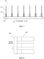
- FIG. 7 is a schematic diagram of an array arrangement of the vibration plate units 200 along the first direction of the fastening structure 400.
- FIG. 8 is a schematic diagram of an array arrangement of the vibration plate units 200 along the second direction of the fastening structure 400.
- the plurality of vibration plate units 200 are arranged in a two-dimensional array structure on the fastening structure 400, to form the heat dissipation assembly 100 shown in FIG.
- An embodiment of a second aspect of the present disclosure provides a heat dissipator 600, including the heat dissipation assembly 100 in the foregoing embodiments.
- the heat dissipator 600 provided in this embodiment is provided with the heat dissipation assembly 100.
- the heat dissipation assembly 100 includes a vibration plate unit 200 and a drive unit 300.
- the vibration plate unit 200 is formed by connecting a vibration plate 210 and a piezoelectric sheet 220.
- the drive unit 300 searches for a target driving frequency within a preset frequency range.
- a first driving frequency output to the piezoelectric sheet 220 is continually changed within the given preset frequency range to obtain a plurality of first output currents corresponding to the first driving frequency, and then the target driving frequency is determined.
- the drive unit 300 applies a driving voltage to the piezoelectric sheet 220 based on the target driving frequency.
- the drive unit 300 intelligently adjusts the target driving frequency output to the piezoelectric sheet 220, which can increase an amplitude of the vibration plate 210, increase a wind speed of the heat dissipation assembly 100, and greatly improve a heat dissipation capability.
- the heat dissipator 600 is provided with a base 610, and the heat dissipation assembly 100 is mounted on the heat dissipator 600 along a normal direction of the base 610, or the heat dissipation assembly 100 is mounted on the heat dissipator 600 along a direction parallel to the base 610.
- the heat dissipator 600 is provided with a base 610, and the heat dissipation assembly 100 may be mounted and fastened on the heat dissipator 600 in two manners: perpendicular to the base 610 or parallel to the base 610.
- the two manners are described as follows.
- the heat dissipation assembly 100 is mounted and fastened along the normal direction of the base 610, that is, mounted along a depth direction of the heat dissipator 600, which can be flexibly located at any height in the normal direction of the base 610, making it easy to install and having satisfactory stability and reliability.
- the heat dissipation assembly 100 is mounted and fastened sideways along the direction parallel to the base 610, that is, located and mounted along a width direction of the heat dissipator 600, which facilitates installation and replacement of the heat dissipation assembly 100.
- an embodiment of a third aspect of the present disclosure provides a control method for a heat dissipation assembly.
- the heat dissipation assembly 100 is provided with a vibration plate unit 200 and a drive unit 300 electrically connected to the vibration plate unit 200, and the vibration plate unit 200 is provided with a vibration plate 210 and at least one piezoelectric sheet 220 connected to the vibration plate 210.
- the control method for a heat dissipation assembly includes, but not limited to, the following steps S110 to S130.
- a first driving frequency output to the piezoelectric sheet is adjusted within a preset frequency range to obtain a plurality of corresponding first output currents.
- a target driving frequency is determined based on the plurality of first output currents.
- a driving voltage is applied to the piezoelectric sheet based on the target driving frequency.
- the vibration plate unit 200 is formed by connecting the vibration plate 210 and the piezoelectric sheet 220.
- the drive unit 300 searches for a target driving frequency within a preset frequency range.
- a first driving frequency output to the piezoelectric sheet 220 is continually changed within the given preset frequency range to obtain a plurality of first output currents corresponding to the first driving frequency, and then the target driving frequency is determined.
- the drive unit 300 applies a driving voltage to the piezoelectric sheet 220 based on the target driving frequency.
- the drive unit 300 intelligently adjusts the target driving frequency output to the piezoelectric sheet 220, which can increase an amplitude of the vibration plate 210 to increase a wind speed of the heat dissipation assembly 100, and greatly improve a heat dissipation capability.
- the drive unit 300 applies an alternating voltage (a periodically changing direct current) to the piezoelectric sheet 220, such that the piezoelectric sheet 220 drives the vibration plate 210 to oscillate periodically, thereby generating an air flow.
- a driving mode of automatic frequency training is used.
- the drive unit 300 may be controlled to adjust the driving frequency based on a status of the heat dissipation assembly 100.
- the target driving frequency output to the piezoelectric sheet 220 can be intelligently adjusted to be close to the natural frequency, such that an amplitude of the vibration plate 210 is maximized as much as possible, which helps improve a heat dissipation effect and resolves drift of a fundamental frequency caused by a conventional fixed-frequency driving mode.
- determining a target driving frequency based on the plurality of first output currents at S 120 includes, but not limited to, the following steps S210 and S220:
- the drive unit 300 continually changes the first driving frequency f within the given preset frequency range, records and stores corresponding first output currents I 1 at first driving frequencies f, determines a current extremum I 0 (a maximum value or a minimum value of the currents) based on the plurality of obtained first output currents Ii, a target driving frequency f 0 corresponding to the current extremum I 0 being a better frequency, and applies a driving voltage to the piezoelectric sheet 220 based on the target driving frequency f 0 .
- a current extremum I 0 a maximum value or a minimum value of the currents
- the trigger condition includes at least one of the following that:
- the trigger condition is added for the drive unit 300 to search for a better frequency. Only when the trigger condition is met, the drive unit 300 searches for the target driving frequency f 0 , which can ensure operation stability of the heat dissipation assembly 100.
- Conditions for triggering the search for a better frequency include: 1. The drive unit 300 is triggered once each time the heat dissipation assembly 100 is started. 2. When the heat dissipation assembly 100 operates continuously, the drive unit 300 regularly detects the second output current I 2 , and compares the second output current I 2 with the internally stored current extremum I 0 .
- the drive unit 300 When a difference between the detected second output current I 2 and the stored current extremum I 0 exceeds the specified preset difference range, the drive unit 300 is triggered to perform the action of searching for a better frequency. 3.
- the drive unit 300 When the heat dissipation assembly 100 operates continuously, based on the preset time period T, the drive unit 300 is triggered to perform the action of searching for a better frequency each time one preset time period T elapses, that is, triggered once when a continuous operation time reaches the preset time period T after the target driving frequency f 0 is determined each time.
- Embodiment one As shown in FIG. 13 , the heat dissipation assembly is started, and the drive unit continually adjusts a first driving frequency f within a preset frequency range, records and stores corresponding first output currents I 1 at different first driving frequencies f, and selects a corresponding target driving frequency f 0 based on a current extremum I 0 of the first output currents I 1 .
- the drive unit applies a driving signal with the frequency f 0 to the piezoelectric sheet, operates continuously, regularly detects a second output current I 2 of the drive unit when the heat dissipation assembly operates continuously, and when a difference between the second output current I 2 and the stored current extremum I 0 exceeds a preset difference range, searches for a target driving frequency f 0 again.
- Embodiment two As shown in FIG. 14 , the heat dissipation assembly is started, and the drive unit continually adjusts a first driving frequency f within a preset frequency range, records and stores corresponding first output currents I 1 at different first driving frequencies f, and selects a corresponding target driving frequency f 0 based on a current extremum I 0 of the first output currents I 1 .
- the drive unit applies a driving signal with the frequency f 0 to the piezoelectric sheet, operates continuously, and after a preset time period T elapses, searches for a target driving frequency f 0 again.
- 2N vibration plate units 200 are provided and divided into two vibration plate arrays 500 each including N vibration plate units 200, where N ⁇ 1.
- the control method for a heat dissipation assembly further includes: applying driving signals with opposite phases to vibration plate units 200 located in different arrays, respectively.
- the 2N vibration plate units 200 may be divided into two vibration plate arrays 500 each includes N vibration plate units 200.
- the drive unit 300 applies driving signals with opposite phases to vibration plate units 200 in different arrays, respectively.
- phase values of the driving signals of different vibration plate units 200 By controlling phase values of the driving signals of different vibration plate units 200, symmetrical vibration can be formed to reduce overall vibration of the heat dissipation assembly 100, thereby reducing noise generated by resonance between the heat dissipation assembly 100 and a heat dissipator 600.
- control method for a heat dissipation assembly 2N+1 vibration plate units 200 are provided and divided into two vibration plate arrays 500, and the two vibration plate arrays 500 respectively include N+1 vibration plate units 200 and N vibration plate units 200, where N ⁇ 1.
- the control method for a heat dissipation assembly further includes: applying driving signals with opposite phases to vibration plate units 200 located in different arrays, respectively.
- the 2N+1 vibration plate units 200 may be divided into two vibration plate arrays 500, with one array including include N+1 vibration plate units 200, and the other array including N vibration plate units 200.
- the drive unit 300 applies driving signals with opposite phases to vibration plate units 200 in different arrays, respectively.
- phase values of the driving signals of different vibration plate units 200 By controlling phase values of the driving signals of different vibration plate units 200, symmetrical vibration can be formed to reduce overall vibration of the heat dissipation assembly 100, thereby reducing noise generated by resonance between the heat dissipation assembly 100 and a heat dissipator 600.
- vibration plate units 200 are arranged.
- two forms namely, an even number of vibration plate units 200 and an odd number of vibration plate units 200 are adopted.
- the vibration plate units 200 are divided into two arrays, and driving voltages with opposite phases are respectively applied thereto, that is, the vibration plate units 200 are driven in portions, which can greatly reduce operating noise.
- An embodiment of a fourth aspect of the present disclosure provides a communication device, including the heat dissipation assembly 100 or the heat dissipator 600 in the foregoing embodiments.
- the communication device provided in this embodiment includes the heat dissipation assembly 100 or the heat dissipator 600 in the foregoing embodiments.
- the heat dissipator 600 is provided with the heat dissipation assembly 100.
- the vibration plate unit 200 is formed by connecting a vibration plate 210 and a piezoelectric sheet 220.
- the drive unit 300 searches for a target driving frequency within a preset frequency range. A first driving frequency output to the piezoelectric sheet 220 is continually changed within the given preset frequency range to obtain a plurality of first output currents corresponding to the first driving frequency, and then the target driving frequency is determined.
- the drive unit 300 applies a driving voltage to the piezoelectric sheet 220 based on the target driving frequency.
- the drive unit 300 intelligently adjusts the target driving frequency output to the piezoelectric sheet 220, which can increase an amplitude of the vibration plate 210 to increase a wind speed of the heat dissipation assembly 100, and greatly improve a heat dissipation capability.
- the communication device in this embodiment of the present disclosure may be an outdoor communication device with high reliability and noise requirements such as an AAU or an RRU, or may be an indoor communication device such as a Building Base Band Unit (BBU).
- BBU Building Base Band Unit
- an embodiment of a fifth aspect of the present disclosure provides an operation control apparatus 1500, including at least one control processor 1510 and a memory 1520 configured to be communicatively connected to the at least one control processor 1510.
- the memory 1520 stores instructions executable by the at least one control processor 1510 which, when executed by the at least one control processor 1510, causes the at least one control processor 1510 to carry out the control method for a heat dissipation assembly in the foregoing embodiments.
- the drive unit 300 searches for a target driving frequency within a preset frequency range.
- a first driving frequency output to the piezoelectric sheet 220 is continually changed within the given preset frequency range to obtain a plurality of first output currents corresponding to the first driving frequency, and then the target driving frequency is determined.
- the drive unit 300 applies a driving voltage to the piezoelectric sheet 220 based on the target driving frequency.
- the drive unit 300 intelligently adjusts the target driving frequency output to the piezoelectric sheet 220, which can increase an amplitude of the vibration plate 210 to increase a wind speed of the heat dissipation assembly 100, and greatly improve a heat dissipation capability.
- An embodiment of a sixth aspect of the present disclosure provides a computer-readable storage medium, storing computer-executable instructions which, when executed by a computer, causes the computer to implement the control method for a heat dissipation assembly in the foregoing embodiments.
- the drive unit 300 searches for a target driving frequency within a preset frequency range.
- a first driving frequency output to the piezoelectric sheet 220 is continually changed within the given preset frequency range to obtain a plurality of first output currents corresponding to the first driving frequency, and then the target driving frequency is determined.
- the drive unit 300 applies a driving voltage to the piezoelectric sheet 220 based on the target driving frequency.
- the drive unit 300 intelligently adjusts the target driving frequency output to the piezoelectric sheet 220, which can increase an amplitude of the vibration plate 210 to increase a wind speed of the heat dissipation assembly 100, and greatly improve a heat dissipation capability.
- the embodiments of the present disclosure include a heat dissipation assembly and a control method therefor, an apparatus, a heat dissipator, and a communication device.
- the heat dissipation assembly includes a vibration plate unit and a drive unit.
- the vibration plate unit is provided with a vibration plate and at least one piezoelectric sheet connected to the vibration plate.
- the drive unit is electrically connected to the vibration plate unit, and the drive unit is configured to: when a trigger condition is met, adjust a first driving frequency output to the piezoelectric sheet within a preset frequency range to obtain a plurality of corresponding first output currents, determine a target driving frequency based on the plurality of first output currents, and apply a driving voltage to the piezoelectric sheet based on the target driving frequency.
- the vibration plate unit is formed by connecting a vibration plate and a piezoelectric sheet.
- the drive unit searches for a target driving frequency within a preset frequency range.
- a first driving frequency output to the piezoelectric sheet is continually changed within the given preset frequency range to obtain a plurality of first output currents corresponding to the first driving frequency, and then the target driving frequency is determined.
- the drive unit applies a driving voltage to the piezoelectric sheet based on the target driving frequency.
- the drive unit intelligently adjusts the target driving frequency output to the piezoelectric sheet, which can increase an amplitude of the vibration plate to increase a wind speed of the heat dissipation assembly, and greatly improve a heat dissipation capability.
Landscapes
- Engineering & Computer Science (AREA)
- Microelectronics & Electronic Packaging (AREA)
- Physics & Mathematics (AREA)
- Thermal Sciences (AREA)
- Computer Networks & Wireless Communication (AREA)
- Mechanical Engineering (AREA)
- Cooling Or The Like Of Electrical Apparatus (AREA)
- General Electrical Machinery Utilizing Piezoelectricity, Electrostriction Or Magnetostriction (AREA)
Abstract
Description
- This application is filed on the basis of
Chinese Patent Application No. 202111493916.1 filed on December 8, 2021 - The present disclosure relates to the technical field of electronic heat dissipation, and more particularly, to a heat dissipation assembly and a control method therefor, an apparatus, a heat dissipator, and a communication device.
- Electronic products generate a large amount of heat during operation. To ensure product reliability, an effective heat dissipation method is needed to control temperature rise. With increasing demands for miniaturization and integration of electronic products, natural heat dissipation methods often cannot provide efficient temperature control. For example, for a Remote Radio Unit (RRU) or an Active Antenna Unit (AAU) of an outdoor communication base station, its mainstream heat dissipation method is natural heat dissipation (heat dissipation through heat dissipation fins). However, as power consumption of the RRU or the AAU increases continuously, a heat dissipation volume of the devices also needs to increase. Therefore, an active cooling method using forced air cooling is needed to reduce the size and weight of the device.
- A piezoelectric vibration fan is suitable to forced air cooling of the RRU or the AAU of the outdoor communication base station due to its high reliability, low noise, low power consumption, high temperature resistance, and small installation space. However, for a piezoelectric vibration fan in the related art, after prolonged use, the amplitude of the vibration plate is significantly reduced, greatly weakening its heat dissipation capability.
- The present disclosure proposes a heat dissipation assembly and a control method therefor, an apparatus, a heat dissipator, and a communication device.
- In accordance with a first aspect of the present disclosure, an embodiment provides a heat dissipation assembly, including a vibration plate unit and a drive unit, the vibration plate unit is provided with a vibration plate, and at least one piezoelectric sheet connected to the vibration plate, the drive unit is electrically connected to the vibration plate unit and is configured to: adjust, in response to meeting a trigger condition, a first driving frequency output to the piezoelectric sheet within a preset frequency range to obtain a plurality of corresponding first output currents, determine a target driving frequency based on the plurality of first output currents, and apply a driving voltage to the piezoelectric sheet based on the target driving frequency.
- In accordance with a second aspect of the present disclosure, an embodiment provides a heat dissipator, including the heat dissipation assembly described in the embodiment of the first aspect of the present disclosure.
- In accordance with a third aspect of the present disclosure, an embodiment provides a control method for a heat dissipation assembly, the heat dissipation assembly is provided with a vibration plate unit and a drive unit electrically connected to the vibration plate unit, and the vibration plate unit is provided with a vibration plate and at least one piezoelectric sheet connected to the vibration plate, the control method for a heat dissipation assembly includes: adjusting, in response to meeting a trigger condition, a first driving frequency output to the piezoelectric sheet within a preset frequency range to obtain a plurality of corresponding first output currents; determining a target driving frequency based on the plurality of first output currents; and applying a driving voltage to the piezoelectric sheet based on the target driving frequency.
- In accordance with a fourth aspect of the present disclosure, an embodiment provides a communication device, including the heat dissipation assembly described in the embodiment of the first aspect of the present disclosure or the heat dissipator described in the embodiment of the second aspect of the present disclosure.
- In accordance with a fifth aspect of the present disclosure, an embodiment provides an operation control apparatus, including at least one control processor and a memory configured to be communicatively connected to the at least one control processor, the memory stores instructions executable by the at least one control processor which, when executed by the at least one control processor, causes the at least one control processor to carry out the control method for a heat dissipation assembly described in the embodiment of the third aspect of the present disclosure.
- In accordance with a sixth aspect of the present disclosure, an embodiment provides a computer-readable storage medium, storing computer-executable instructions which, when executed by a computer, causes the computer to carry out the control method for a heat dissipation assembly described in the embodiment of the third aspect of the present disclosure.
- Additional features and advantages of the present disclosure will be set forth in the description which follows, and in part will be apparent from the description, or may be learned by the practice of the present disclosure. The objects and other advantages of the present disclosure can be realized and obtained by the structures particularly pointed out in the description, claims, and drawings.
- The drawings are provided for a further understanding of the technical schemes of the present disclosure, and constitute a part of the description. The drawings and the embodiments of the present disclosure are used to illustrate the technical schemes of the present disclosure, and are not intended to limit the technical schemes of the present disclosure.
- The present disclosure is further described below in conjunction with the accompanying drawings and embodiments.
-
FIG. 1 is a schematic structural diagram of a heat dissipation assembly according to an embodiment of the present disclosure; -
FIG. 2 is a schematic structural diagram of a vibration plate unit with two piezoelectric sheets according to another embodiment of the present disclosure; -
FIG. 3 is a schematic structural diagram of a vibration plate unit with a single piezoelectric sheet according to another embodiment of the present disclosure; -
FIG. 4 is a schematic structural diagram of a heat dissipation assembly provided with 2N vibration plate units according to another embodiment of the present disclosure; -
FIG. 5 is a schematic structural diagram of a heat dissipation assembly provided with 2N+1 vibration plate units according to another embodiment of the present disclosure; -
FIG. 6 is a schematic structural diagram of a heat dissipation assembly with vibration plate units arranged in a two-dimensional array according to another embodiment of the present disclosure; -
FIG. 7 is a schematic diagram of an array arrangement of vibration plate units along a first direction of a fastening structure according to another embodiment of the present disclosure; -
FIG. 8 is a schematic diagram of an array arrangement of vibration plate units along a second direction of a fastening structure according to another embodiment of the present disclosure; -
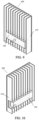
FIG. 9 is a schematic structural diagram of a heat dissipator according to an embodiment of the present disclosure; -
FIG. 10 is a schematic structural diagram of a heat dissipator according to another embodiment of the present disclosure; -
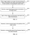
FIG. 11 is a flowchart of a control method for a heat dissipation assembly according to an embodiment of the present disclosure; -
FIG. 12 is a flowchart of a control method for a heat dissipation assembly according to another embodiment of the present disclosure; -
FIG. 13 is a flowchart of a control method for a heat dissipation assembly according to another embodiment of the present disclosure; -
FIG. 14 is a flowchart of a control method for a heat dissipation assembly according to another embodiment of the present disclosure; and -
FIG. 15 is a schematic structural diagram of an operation control apparatus according to an embodiment of the present disclosure. - This section will describe in detail some embodiments of the present disclosure. Some embodiments of the present disclosure are shown in the accompanying drawings. The accompanying drawings are used to supplement the descriptions of the specification with graphics, such that people can understand each technical feature and the overall technical scheme of the present disclosure intuitively and vividly, but they shall not be understood as limiting the protection scope of the present disclosure.
- In the descriptions of the present disclosure, "several" means one or more, "a plural of/multiple" means two or more, "greater than", "less than", "exceed" or variants thereof prior to a number or series of numbers is understood to not include the number adjacent to the term, and "above", "below", "within", and the like are understood to include the number. If used herein, the terms such as "first", "second", and the like are merely used for distinguishing technical features, and are not intended to indicate or imply relative importance, or implicitly point out the number of the indicated technical features, or implicitly point out the precedence order of the indicated technical features.
- In the descriptions of the present disclosure, unless otherwise explicitly limited, terms such as "arrange", "install", and "connect" should be understood in a broad sense. Those having ordinary skills in the art can properly determine meanings of the terms in the present disclosure based on contents of the technical schemes.
- A fan is a device that blows air. A commonly-used conventional rotary fan is limited duration application in outdoor scenes due to its unsatisfactory reliability, large noise, and high energy consumption caused by characteristics of a bearing and a blade. A piezoelectric vibration fan is applicable to forced air cooling of an RRU or an AAU of an outdoor communication base station due to its technical characteristics of high reliability, low noise, low power consumption, high temperature resistance, and small installation space.
- In some embodiments, for practical application of piezoelectric vibration fans in heat dissipation by forced air cooling, piezoelectric vibration fans in the related art generally use a fixed-frequency driving mode. A fan vibration plate is fatigued after operating under long-term alternating stress. As a result, stiffness changes, and a natural frequency of the piezoelectric vibration fan shifts. In addition, in some specific environments, when foreign matter adheres to the fan vibration plate, the natural frequency of the system may also change, causing a fundamental frequency of the piezoelectric vibration fan to drift. Consequently, an amplitude is significantly reduced, and a heat dissipation capability is weakened. Typically, the natural frequency of the system changes due to accumulation of dust, grease, or catkins on the fan vibration plate. In this case, if the fixed-frequency driving mode is still used, a resonance phenomenon cannot occur. Consequently, an amplitude of the vibration plate becomes smaller, and a heat dissipation capability is weakened.
- Embodiments of the present disclosure provide a heat dissipation assembly, a control method therefor, an apparatus, a heat dissipator, and a communication device, which can intelligently adjust a target driving frequency output to a piezoelectric sheet, to increase an amplitude of a vibration plate, and greatly improve a heat dissipation capability.
- The embodiments of the present disclosure will be described blow in conjunction with the accompanying drawings.
- As shown in
FIG. 1 , an embodiment of a first aspect of the present disclosure provides aheat dissipation assembly 100, including avibration plate unit 200 and adrive unit 300. Thevibration plate unit 200 is provided with avibration plate 210, and at least onepiezoelectric sheet 220 connected to thevibration plate 210. Thedrive unit 300 is electrically connected to thevibration plate unit 200, and thedrive unit 300 is configured to: when a trigger condition is met, adjust a first driving frequency output to thepiezoelectric sheet 220 within a preset frequency range to obtain a plurality of corresponding first output currents, determine a target driving frequency based on the plurality of first output currents, and apply a driving voltage to thepiezoelectric sheet 220 based on the target driving frequency. - In this embodiment, the
vibration plate unit 200 is formed by connecting thevibration plate 210 and thepiezoelectric sheet 220. When a trigger condition is met, thedrive unit 300 searches for a target driving frequency within a preset frequency range. A first driving frequency output to thepiezoelectric sheet 220 is continually changed within the given preset frequency range to obtain a plurality of first output currents corresponding to the first driving frequency, and then the target driving frequency is determined. Thedrive unit 300 applies a driving voltage to thepiezoelectric sheet 220 based on the target driving frequency. Thedrive unit 300 intelligently adjusts the target driving frequency output to thepiezoelectric sheet 220, which can increase an amplitude of thevibration plate 210 to increase a wind speed of theheat dissipation assembly 100, and greatly improve a heat dissipation capability. - It should be noted that a resonance phenomenon is that when a frequency of an input driving voltage is equal to a natural frequency of the
vibration plate unit 200, an overhanging end of thevibration plate 210 reaches a maximum amplitude. Different from a fixed-frequency driving mode used in some cases, theheat dissipation assembly 100 in this embodiment of the present disclosure uses a driving mode of automatic frequency training. Thedrive unit 300 may adjust the driving frequency based on a status of theheat dissipation assembly 100. When the natural frequency changes, the target driving frequency output to thepiezoelectric sheet 220 can be intelligently adjusted to be consistent with the natural frequency, such that thevibration plate 210 always maintains a maximum amplitude under a resonance condition, which improves a heat dissipation effect and resolves drift of a fundamental frequency caused by the conventional natural-frequency driving mode. - It should be noted that the
piezoelectric sheet 220 is made of a piezoelectric ceramic material, thevibration plate 210 is made of an elastic material, and thepiezoelectric sheet 220 is bonded to thevibration plate 210 to form thevibration plate unit 200. Thedrive unit 300 applies an alternating voltage (a periodically changing direct current) to thepiezoelectric sheet 220, and thepiezoelectric sheet 220 performs periodic contraction based on an inverse piezoelectric effect of the piezoelectric material, which drives thevibration plate 210 to oscillate periodically, thereby driving fluid nearby to flow directionally. - In an embodiment, the
drive unit 300 uses an intermittent direct current to drive thepiezoelectric sheet 220. When the target driving frequency is close to the natural frequency of thevibration plate unit 200, thepiezoelectric sheet 220 can drive thevibration plate 210 to vibrate to generate an objective directional wind speed, thereby ensuring a satisfactory heat dissipation effect. - It can be understood that the
heat dissipation assembly 100 is a piezoelectric vibration fan. Since theheat dissipation assembly 100 generates a wind speed through oscillation of thevibration plate 210, heat exchange efficiency of a heat dissipator can be effectively improved. In addition, there are no bearing parts in theheat dissipation assembly 100, which helps improve reliability of theheat dissipation assembly 100, and is different from a conventional rotary fan used in some cases. Theheat dissipation assembly 100 in this embodiment of the present disclosure effectively reduces system noise, resolves a problem of unsatisfactory heat dissipation capability of a conventional heat dissipation method for an outdoor communication device while ensuring reliability, and achieves a significant decrease in the size and weight of the communication device. - In the
heat dissipation assembly 100, determining a target driving frequency based on the plurality of first output currents includes: - determining a current extremum based on the plurality of first output currents; and
- determining a corresponding target driving frequency based on the current extremum.
- In this embodiment, the
drive unit 300 continually changes the first driving frequency within the given preset frequency range, records and stores corresponding first output currents at first driving frequencies, determines a current extremum (a maximum value or a minimum value of the currents) based on the plurality of obtained first output currents, a target driving frequency corresponding to the current extremum being a better frequency, and applies a driving voltage to thepiezoelectric sheet 220 based on the target driving frequency. - It should be noted that it is found through experiments that within the given frequency range, the driving frequency corresponding to the current extremum leads to a maximum amplitude of the
vibration plate 210 and a maximum wind speed of theheat dissipation assembly 100, thereby improving a heat dissipation effect. Therefore, the target driving frequency is a better frequency. - In the
heat dissipation assembly 100, the trigger condition includes at least one of the following that: - the
heat dissipation assembly 100 is started; or - a second output current of the
drive unit 300 is detected when theheat dissipation assembly 100 operates continuously, and a difference between the second output current and the current extremum exceeds a preset difference range; or - a continuous operation time of the
heat dissipation assembly 100 reaches a preset time period after the target driving frequency is determined each time. - In this embodiment, the trigger condition is added for the
drive unit 300 to search for a better frequency. Only when the trigger condition is met, thedrive unit 300 searches for the target driving frequency, which can ensure operation stability of theheat dissipation assembly 100. The trigger condition may be met in the following three cases: - 1. The
drive unit 300 is triggered once each time theheat dissipation assembly 100 is started. - 2. When the
heat dissipation assembly 100 operates continuously, thedrive unit 300 regularly detects the second output current, and compares the second output current with the internally stored current extremum. When a difference between the detected second output current and the stored current extremum exceeds the specified preset difference range, thedrive unit 300 is triggered to perform the action of searching for a better frequency. - 3. When the
heat dissipation assembly 100 operates continuously, based on the preset time period, thedrive unit 300 is triggered to perform the action of searching for a better frequency each time one preset time period elapses, that is, triggered once when a continuous operation time reaches the preset time period after the target driving frequency is determined each time. - As shown in
FIG. 1 , theheat dissipation assembly 100 further includes afastening structure 400. Thevibration plate unit 200 is connected to thefastening structure 400, and thevibration plate 210 has one end connected to thefastening structure 400 and the other end overhanging. - In this embodiment, the
fastening structure 400 provides a boundary fastening condition for thevibration plate unit 200. Thevibration plate unit 200 may be fastened to thefastening structure 400 by injection molding or mechanical crimping, to ensure operation stability of thevibration plate 210. - It should be noted that the
drive unit 300 may be independent of thevibration plate unit 200 and thefastening structure 400 such that thevibration plate unit 200, thefastening structure 400, and thedrive unit 300 form a splitheat dissipation assembly 100, or may be integrated into thefastening structure 400 such that thevibration plate unit 200, thefastening structure 400, and thedrive unit 300 form an integratedheat dissipation assembly 100. - In the
heat dissipation assembly 100, thepiezoelectric sheet 220 is arranged at an end of thevibration plate 210 connected to thefastening structure 400. Thevibration plate 210 can oscillate periodically as driven by thepiezoelectric sheet 220, to generate a wind speed, thereby ensuring a satisfactory heat dissipation effect. - As shown in
FIG. 2 andFIG. 3 , in theheat dissipation assembly 100, one side of thevibration plate 210 is provided with thepiezoelectric sheet 220, or two sides of thevibration plate 210 are both provided with thepiezoelectric sheet 220. - As shown in
FIG. 2 andFIG. 3 , in this embodiment, thevibration plate unit 200 may be formed by connecting onepiezoelectric sheet 220 to one side of thevibration plate 210, or may be formed by connecting onepiezoelectric sheet 220 to each of the two sides of thevibration plate 210. When twopiezoelectric sheets 220 are arranged on the two sides of thevibration plate 210, thevibration plate unit 200 can generate a greater driving force, to increase the wind speed of theheat dissipation assembly 100. - As shown in
FIG. 4 , in theheat dissipation assembly 100, 2Nvibration plate units 200 are provided and divided into twovibration plate arrays 500 each including Nvibration plate units 200, and thedrive unit 300 is further configured to apply driving signals with opposite phases to thevibration plate units 200 located in different arrays respectively, where N≥1. - In this embodiment, when an even number (2N) of
vibration plate units 200 are arranged, the 2Nvibration plate units 200 may be divided into twovibration plate arrays 500 each including Nvibration plate units 200. During driving, thedrive unit 300 respectively applies driving signals with opposite phases to thevibration plate units 200 in different arrays. By controlling phase values of driving signals applied to differentvibration plate units 200, symmetrical vibration can be formed to reduce overall vibration of theheat dissipation assembly 100, thereby reducing noise generated by resonance between theheat dissipation assembly 100 and aheat dissipator 600. It should be noted that in this embodiment of the present disclosure, a selection method for the Nvibration plate units 200 in each array is not limited. For example, N adjacentvibration plate units 200 may be selected, or Nvibration plate units 200 may be selected alternately. - As shown in
FIG. 5 , in theheat dissipation assembly 100, 2N+1vibration plate units 200 are provided and divided into twovibration plate arrays 500. The twovibration plate arrays 500 respectively include N+1vibration plate units 200 and Nvibration plate units 200, and thedrive unit 300 is further configured to apply driving signals with opposite phases tovibration plate units 200 located in different arrays respectively, where N≥1. - In this embodiment, when an odd number (2N+1) of
vibration plate units 200 are arranged, the 2N+1vibration plate units 200 may be divided into twovibration plate arrays 500, with one array including include N+1vibration plate units 200, and the other array including Nvibration plate units 200. During operation, thedrive unit 300 applies driving signals with opposite phases to thevibration plate units 200 in different arrays, respectively. By controlling phase values of driving signals applied to differentvibration plate units 200, symmetrical vibration can be formed to reduce overall vibration of theheat dissipation assembly 100, thereby reducing noise generated by resonance between theheat dissipation assembly 100 and aheat dissipator 600. - It should be noted that a plurality of
vibration plate units 200 are arranged. In this embodiment of the present disclosure, two forms, namely, an even number ofvibration plate units 200 and an odd number ofvibration plate units 200 are adopted. Thevibration plate units 200 are divided into two arrays, and driving voltages with opposite phases are respectively applied thereto, which can greatly reduce operating noise. - It should be noted that the
drive unit 300 adjusts a frequency during operation. In this embodiment of the present disclosure, the number ofdrive units 300 is not limited. For example, eachvibration plate unit 200 may have onedrive unit 300 configured, or a plurality ofvibration plates 210 may share onedrive unit 300, to form theheat dissipation assembly 100 of the present disclosure. - As shown in
FIG. 6 , in theheat dissipation assembly 100, a plurality ofvibration plate units 200 are provided and arranged in an array along a first direction and a second direction of thefastening structure 400. - As shown in
FIG. 6 to FIG. 8 , in this embodiment, theheat dissipation assembly 100 includes a plurality ofvibration plate units 200 arranged in an array. Thevibration plate units 200 are arranged on thefastening structure 400 in an array including two direction dimensions.FIG. 7 is a schematic diagram of an array arrangement of thevibration plate units 200 along the first direction of thefastening structure 400.FIG. 8 is a schematic diagram of an array arrangement of thevibration plate units 200 along the second direction of thefastening structure 400. Through the array arrangement along the first direction and the second direction of thefastening structure 400, the plurality ofvibration plate units 200 are arranged in a two-dimensional array structure on thefastening structure 400, to form theheat dissipation assembly 100 shown inFIG. 6 , which can increase an air outlet area of theheat dissipation assembly 100, to help improve heat dissipation performance, and resolve a problem that a wind speed of a conventional piezoelectric vibration fans attenuates excessively quickly in heat dissipation fins. - An embodiment of a second aspect of the present disclosure provides a
heat dissipator 600, including theheat dissipation assembly 100 in the foregoing embodiments. - As shown in
FIG. 1 ,FIG. 9, and FIG. 10 , theheat dissipator 600 provided in this embodiment is provided with theheat dissipation assembly 100. Theheat dissipation assembly 100 includes avibration plate unit 200 and adrive unit 300. Thevibration plate unit 200 is formed by connecting avibration plate 210 and apiezoelectric sheet 220. When a trigger condition is met, thedrive unit 300 searches for a target driving frequency within a preset frequency range. A first driving frequency output to thepiezoelectric sheet 220 is continually changed within the given preset frequency range to obtain a plurality of first output currents corresponding to the first driving frequency, and then the target driving frequency is determined. Thedrive unit 300 applies a driving voltage to thepiezoelectric sheet 220 based on the target driving frequency. Thedrive unit 300 intelligently adjusts the target driving frequency output to thepiezoelectric sheet 220, which can increase an amplitude of thevibration plate 210, increase a wind speed of theheat dissipation assembly 100, and greatly improve a heat dissipation capability. - As shown in
FIG. 9 and FIG. 10 , theheat dissipator 600 is provided with abase 610, and theheat dissipation assembly 100 is mounted on theheat dissipator 600 along a normal direction of thebase 610, or theheat dissipation assembly 100 is mounted on theheat dissipator 600 along a direction parallel to thebase 610. - In this embodiment, the
heat dissipator 600 is provided with abase 610, and theheat dissipation assembly 100 may be mounted and fastened on theheat dissipator 600 in two manners: perpendicular to the base 610 or parallel to thebase 610. The two manners are described as follows. - Manner one: As shown in
FIG. 9 , theheat dissipation assembly 100 is mounted and fastened along the normal direction of thebase 610, that is, mounted along a depth direction of theheat dissipator 600, which can be flexibly located at any height in the normal direction of thebase 610, making it easy to install and having satisfactory stability and reliability. - Manner two: As shown in
FIG. 10 , theheat dissipation assembly 100 is mounted and fastened sideways along the direction parallel to thebase 610, that is, located and mounted along a width direction of theheat dissipator 600, which facilitates installation and replacement of theheat dissipation assembly 100. - As shown in
FIG. 1 andFIG. 11 , an embodiment of a third aspect of the present disclosure provides a control method for a heat dissipation assembly. Theheat dissipation assembly 100 is provided with avibration plate unit 200 and adrive unit 300 electrically connected to thevibration plate unit 200, and thevibration plate unit 200 is provided with avibration plate 210 and at least onepiezoelectric sheet 220 connected to thevibration plate 210. The control method for a heat dissipation assembly includes, but not limited to, the following steps S110 to S130. - At S110, when a trigger condition is met, a first driving frequency output to the piezoelectric sheet is adjusted within a preset frequency range to obtain a plurality of corresponding first output currents.
- At S120, a target driving frequency is determined based on the plurality of first output currents.
- At
S 130, a driving voltage is applied to the piezoelectric sheet based on the target driving frequency. - In this embodiment, the
vibration plate unit 200 is formed by connecting thevibration plate 210 and thepiezoelectric sheet 220. When a trigger condition is met, thedrive unit 300 searches for a target driving frequency within a preset frequency range. A first driving frequency output to thepiezoelectric sheet 220 is continually changed within the given preset frequency range to obtain a plurality of first output currents corresponding to the first driving frequency, and then the target driving frequency is determined. Thedrive unit 300 applies a driving voltage to thepiezoelectric sheet 220 based on the target driving frequency. Thedrive unit 300 intelligently adjusts the target driving frequency output to thepiezoelectric sheet 220, which can increase an amplitude of thevibration plate 210 to increase a wind speed of theheat dissipation assembly 100, and greatly improve a heat dissipation capability. - It should be noted that the
drive unit 300 applies an alternating voltage (a periodically changing direct current) to thepiezoelectric sheet 220, such that thepiezoelectric sheet 220 drives thevibration plate 210 to oscillate periodically, thereby generating an air flow. In the control method for a heat dissipation assembly in this embodiment of the present disclosure, a driving mode of automatic frequency training is used. Thedrive unit 300 may be controlled to adjust the driving frequency based on a status of theheat dissipation assembly 100. When a natural frequency of theheat dissipation assembly 100 changes, the target driving frequency output to thepiezoelectric sheet 220 can be intelligently adjusted to be close to the natural frequency, such that an amplitude of thevibration plate 210 is maximized as much as possible, which helps improve a heat dissipation effect and resolves drift of a fundamental frequency caused by a conventional fixed-frequency driving mode. - As shown in
FIG. 12 , in the control method for a heat dissipation assembly, determining a target driving frequency based on the plurality of first output currents at S 120 includes, but not limited to, the following steps S210 and S220: - At S210, a current extremum is determined based on the plurality of first output currents.
- At S220, a corresponding target driving frequency is determined based on the current extremum.
- In this embodiment, the
drive unit 300 continually changes the first driving frequency f within the given preset frequency range, records and stores corresponding first output currents I1 at first driving frequencies f, determines a current extremum I0 (a maximum value or a minimum value of the currents) based on the plurality of obtained first output currents Ii, a target driving frequency f0 corresponding to the current extremum I0 being a better frequency, and applies a driving voltage to thepiezoelectric sheet 220 based on the target driving frequency f0. - In the control method for a heat dissipation assembly, the trigger condition includes at least one of the following that:
- the
heat dissipation assembly 100 is started; or - a second output current I2 of the
drive unit 300 is detected when theheat dissipation assembly 100 operates continuously, and a difference between the second output current I2 and the current extremum I0 exceeds a preset difference range; or - a continuous operation time of the
heat dissipation assembly 100 reaches a preset time period after the target driving frequency f0 is determined each time. - In this embodiment, the trigger condition is added for the
drive unit 300 to search for a better frequency. Only when the trigger condition is met, thedrive unit 300 searches for the target driving frequency f0, which can ensure operation stability of theheat dissipation assembly 100. Conditions for triggering the search for a better frequency include: 1. Thedrive unit 300 is triggered once each time theheat dissipation assembly 100 is started. 2. When theheat dissipation assembly 100 operates continuously, thedrive unit 300 regularly detects the second output current I2, and compares the second output current I2 with the internally stored current extremum I0. When a difference between the detected second output current I2 and the stored current extremum I0 exceeds the specified preset difference range, thedrive unit 300 is triggered to perform the action of searching for a better frequency. 3. When theheat dissipation assembly 100 operates continuously, based on the preset time period T, thedrive unit 300 is triggered to perform the action of searching for a better frequency each time one preset time period T elapses, that is, triggered once when a continuous operation time reaches the preset time period T after the target driving frequency f0 is determined each time. - Two embodiments of the control method for a heat dissipation assembly in the present disclosure are described below.
- Embodiment one: As shown in
FIG. 13 , the heat dissipation assembly is started, and the drive unit continually adjusts a first driving frequency f within a preset frequency range, records and stores corresponding first output currents I1 at different first driving frequencies f, and selects a corresponding target driving frequency f0 based on a current extremum I0 of the first output currents I1. The drive unit applies a driving signal with the frequency f0 to the piezoelectric sheet, operates continuously, regularly detects a second output current I2 of the drive unit when the heat dissipation assembly operates continuously, and when a difference between the second output current I2 and the stored current extremum I0 exceeds a preset difference range, searches for a target driving frequency f0 again. - Embodiment two: As shown in
FIG. 14 , the heat dissipation assembly is started, and the drive unit continually adjusts a first driving frequency f within a preset frequency range, records and stores corresponding first output currents I1 at different first driving frequencies f, and selects a corresponding target driving frequency f0 based on a current extremum I0 of the first output currents I1. The drive unit applies a driving signal with the frequency f0 to the piezoelectric sheet, operates continuously, and after a preset time period T elapses, searches for a target driving frequency f0 again. - As shown in
FIG. 4 , in the control method for a heat dissipation assembly, 2Nvibration plate units 200 are provided and divided into twovibration plate arrays 500 each including Nvibration plate units 200, where N≥1. The control method for a heat dissipation assembly further includes:
applying driving signals with opposite phases tovibration plate units 200 located in different arrays, respectively. - In this embodiment, when an even number (2N) of
vibration plate units 200 are arranged, the 2Nvibration plate units 200 may be divided into twovibration plate arrays 500 each includes Nvibration plate units 200. During driving, thedrive unit 300 applies driving signals with opposite phases tovibration plate units 200 in different arrays, respectively. By controlling phase values of the driving signals of differentvibration plate units 200, symmetrical vibration can be formed to reduce overall vibration of theheat dissipation assembly 100, thereby reducing noise generated by resonance between theheat dissipation assembly 100 and aheat dissipator 600. - As shown in
FIG. 5 , in the control method for a heat dissipation assembly, 2N+1vibration plate units 200 are provided and divided into twovibration plate arrays 500, and the twovibration plate arrays 500 respectively include N+1vibration plate units 200 and Nvibration plate units 200, where N≥1. The control method for a heat dissipation assembly further includes:
applying driving signals with opposite phases tovibration plate units 200 located in different arrays, respectively. - In this embodiment, when an odd number (2N+1) of
vibration plate units 200 are arranged, the 2N+1vibration plate units 200 may be divided into twovibration plate arrays 500, with one array including include N+1vibration plate units 200, and the other array including Nvibration plate units 200. During operation, thedrive unit 300 applies driving signals with opposite phases tovibration plate units 200 in different arrays, respectively. By controlling phase values of the driving signals of differentvibration plate units 200, symmetrical vibration can be formed to reduce overall vibration of theheat dissipation assembly 100, thereby reducing noise generated by resonance between theheat dissipation assembly 100 and aheat dissipator 600. - It should be noted that a plurality of
vibration plate units 200 are arranged. In this embodiment of the present disclosure, two forms, namely, an even number ofvibration plate units 200 and an odd number ofvibration plate units 200 are adopted. Thevibration plate units 200 are divided into two arrays, and driving voltages with opposite phases are respectively applied thereto, that is, thevibration plate units 200 are driven in portions, which can greatly reduce operating noise. - An embodiment of a fourth aspect of the present disclosure provides a communication device, including the
heat dissipation assembly 100 or theheat dissipator 600 in the foregoing embodiments. - The communication device provided in this embodiment includes the
heat dissipation assembly 100 or theheat dissipator 600 in the foregoing embodiments. Theheat dissipator 600 is provided with theheat dissipation assembly 100. Thevibration plate unit 200 is formed by connecting avibration plate 210 and apiezoelectric sheet 220. When a trigger condition is met, thedrive unit 300 searches for a target driving frequency within a preset frequency range. A first driving frequency output to thepiezoelectric sheet 220 is continually changed within the given preset frequency range to obtain a plurality of first output currents corresponding to the first driving frequency, and then the target driving frequency is determined. Thedrive unit 300 applies a driving voltage to thepiezoelectric sheet 220 based on the target driving frequency. Thedrive unit 300 intelligently adjusts the target driving frequency output to thepiezoelectric sheet 220, which can increase an amplitude of thevibration plate 210 to increase a wind speed of theheat dissipation assembly 100, and greatly improve a heat dissipation capability. - The communication device in this embodiment of the present disclosure may be an outdoor communication device with high reliability and noise requirements such as an AAU or an RRU, or may be an indoor communication device such as a Building Base Band Unit (BBU).
- As shown in
FIG. 15 , an embodiment of a fifth aspect of the present disclosure provides anoperation control apparatus 1500, including at least onecontrol processor 1510 and amemory 1520 configured to be communicatively connected to the at least onecontrol processor 1510. Thememory 1520 stores instructions executable by the at least onecontrol processor 1510 which, when executed by the at least onecontrol processor 1510, causes the at least onecontrol processor 1510 to carry out the control method for a heat dissipation assembly in the foregoing embodiments. - In the operation control apparatus provided in this embodiment, when a trigger condition is met, the
drive unit 300 searches for a target driving frequency within a preset frequency range. A first driving frequency output to thepiezoelectric sheet 220 is continually changed within the given preset frequency range to obtain a plurality of first output currents corresponding to the first driving frequency, and then the target driving frequency is determined. Thedrive unit 300 applies a driving voltage to thepiezoelectric sheet 220 based on the target driving frequency. Thedrive unit 300 intelligently adjusts the target driving frequency output to thepiezoelectric sheet 220, which can increase an amplitude of thevibration plate 210 to increase a wind speed of theheat dissipation assembly 100, and greatly improve a heat dissipation capability. - An embodiment of a sixth aspect of the present disclosure provides a computer-readable storage medium, storing computer-executable instructions which, when executed by a computer, causes the computer to implement the control method for a heat dissipation assembly in the foregoing embodiments.
- In the computer-readable storage medium provided in this embodiment, when a trigger condition is met, the
drive unit 300 searches for a target driving frequency within a preset frequency range. A first driving frequency output to thepiezoelectric sheet 220 is continually changed within the given preset frequency range to obtain a plurality of first output currents corresponding to the first driving frequency, and then the target driving frequency is determined. Thedrive unit 300 applies a driving voltage to thepiezoelectric sheet 220 based on the target driving frequency. Thedrive unit 300 intelligently adjusts the target driving frequency output to thepiezoelectric sheet 220, which can increase an amplitude of thevibration plate 210 to increase a wind speed of theheat dissipation assembly 100, and greatly improve a heat dissipation capability. - The embodiments of the present disclosure include a heat dissipation assembly and a control method therefor, an apparatus, a heat dissipator, and a communication device. The heat dissipation assembly includes a vibration plate unit and a drive unit. The vibration plate unit is provided with a vibration plate and at least one piezoelectric sheet connected to the vibration plate. The drive unit is electrically connected to the vibration plate unit, and the drive unit is configured to: when a trigger condition is met, adjust a first driving frequency output to the piezoelectric sheet within a preset frequency range to obtain a plurality of corresponding first output currents, determine a target driving frequency based on the plurality of first output currents, and apply a driving voltage to the piezoelectric sheet based on the target driving frequency. According to the schemes provided in the embodiments of the present disclosure, in the embodiments, the vibration plate unit is formed by connecting a vibration plate and a piezoelectric sheet. When a trigger condition is met, the drive unit searches for a target driving frequency within a preset frequency range. A first driving frequency output to the piezoelectric sheet is continually changed within the given preset frequency range to obtain a plurality of first output currents corresponding to the first driving frequency, and then the target driving frequency is determined. The drive unit applies a driving voltage to the piezoelectric sheet based on the target driving frequency. The drive unit intelligently adjusts the target driving frequency output to the piezoelectric sheet, which can increase an amplitude of the vibration plate to increase a wind speed of the heat dissipation assembly, and greatly improve a heat dissipation capability.
- The embodiments of the present disclosure are described in detail above with reference to the accompanying drawings, but the present disclosure is not limited thereto. Various changes can be made within the knowledge scope of those having ordinary skills in the art without departing from the protection scope of the present disclosure.
Claims (19)
- A heat dissipation assembly, comprising:a vibration plate unit, provided with a vibration plate and at least one piezoelectric sheet connected to the vibration plate; anda drive unit, electrically connected to the vibration plate unit, and the drive unit is configured to:
adjust, in response to meeting a trigger condition, a first driving frequency output to the piezoelectric sheet within a preset frequency range to obtain a plurality of corresponding first output currents, determine a target driving frequency based on the plurality of first output currents, and apply a driving voltage to the piezoelectric sheet based on the target driving frequency. - The heat dissipation assembly of claim 1, wherein determining a target driving frequency based on the plurality of first output currents comprises:determining a current extremum based on the plurality of first output currents; anddetermining a corresponding target driving frequency based on the current extremum.
- The heat dissipation assembly of claim 2, wherein the trigger condition comprises at least one of the following that:the heat dissipation assembly is started; ora second output current of the drive unit is detected when the heat dissipation assembly operates continuously, and a difference between the second output current and the current extremum exceeds a preset difference range; ora continuous operation time of the heat dissipation assembly reaches a preset time period after the target driving frequency is determined each time.
- The heat dissipation assembly of claim 1, further comprising a fastening structure, wherein the vibration plate unit is connected to the fastening structure, and the vibration plate has one end connected to the fastening structure and the other end overhanging.
- The heat dissipation assembly of claim 4, wherein the piezoelectric sheet is arranged at an end of the vibration plate connected to the fastening structure.
- The heat dissipation assembly of claim 1, wherein one side of the vibration plate is provided with the piezoelectric sheet, or two sides of the vibration plate are both provided with the piezoelectric sheet.
- The heat dissipation assembly of claim 1, wherein 2N vibration plate units are provided and divided into two vibration plate arrays each comprising N vibration plate units, and the drive unit is further configured to apply driving signals with opposite phases to vibration plate units located in different arrays respectively, wherein N≥1.
- The heat dissipation assembly of claim 1, wherein 2N+1 vibration plate units are provided and divided into two vibration plate arrays, the two vibration plate arrays respectively comprise N+1 vibration plate units and N vibration plate units, and the drive unit is further configured to apply driving signals with opposite phases to vibration plate units located in different arrays respectively, wherein N≥1.
- The heat dissipation assembly of claim 4, wherein a plurality of vibration plate units are provided and arranged in an array along a first direction and a second direction of the fastening structure.
- A heat dissipator, comprising the heat dissipation assembly of any of claims 1 to 9.
- The heat dissipator of claim 10, wherein the heat dissipator is provided with a base, and the heat dissipation assembly is mounted on the heat dissipator along a normal direction of the base, or the heat dissipation assembly is mounted on the heat dissipator along a direction parallel to the base.
- A control method for a heat dissipation assembly, wherein the heat dissipation assembly is provided with a vibration plate unit and a drive unit electrically connected to the vibration plate unit, and the vibration plate unit is provided with a vibration plate and at least one piezoelectric sheet connected to the vibration plate; and the control method comprises:adjusting, in response to meeting a trigger condition, a first driving frequency output to the piezoelectric sheet within a preset frequency range to obtain a plurality of corresponding first output currents;determining a target driving frequency based on the plurality of first output currents; andapplying a driving voltage to the piezoelectric sheet based on the target driving frequency.
- The control method of claim 12, wherein determining a target driving frequency based on the plurality of first output currents comprises:determining a current extremum based on the plurality of first output currents; anddetermining a corresponding target driving frequency based on the current extremum.
- The control method of claim 13, wherein the trigger condition comprises at least one of the following that:the heat dissipation assembly is started; ora second output current of the drive unit is detected when the heat dissipation assembly operates continuously, and a difference between the second output current and the current extremum exceeds a preset difference range; ora continuous operation time of the heat dissipation assembly reaches a preset time period after the target driving frequency is determined each time.
- The control method of claim 12, wherein 2N vibration plate units are provided and divided into two vibration plate arrays each comprising N vibration plate units, wherein N≥1, and the control method further comprises:
applying driving signals with opposite phases to vibration plate units located in different arrays, respectively. - The control method of claim 12, wherein 2N+1 vibration plate units are provided and divided into two vibration plate arrays, the two vibration plate arrays respectively comprise N+1 vibration plate units and N vibration plate units, wherein N≥1, and the control method further comprises:
applying driving signals with opposite phases to vibration plate units located in different arrays, respectively. - A communication device, comprising the heat dissipation assembly of any of claims 1 to 9 or the heat dissipator of claim 10 or 11.
- An operation control apparatus, comprising at least one control processor and a memory configured to be communicatively connected to the at least one control processor, wherein the memory stores instructions executable by the at least one control processor which, when executed by the at least one control processor, causes the at least one control processor to carry out the control method of any of claims 12 to 16.
- A computer-readable storage medium, storing computer-executable instructions which, when executed by a computer, cause the computer to carry out the control method of any of claims 12 to 16.
Applications Claiming Priority (2)
| Application Number | Priority Date | Filing Date | Title |
|---|---|---|---|
| CN202111493916.1A CN116321913A (en) | 2021-12-08 | 2021-12-08 | Heat dissipation component and its control method, device, heat sink, communication equipment |
| PCT/CN2022/136640 WO2023103978A1 (en) | 2021-12-08 | 2022-12-05 | Heat dissipation assembly and control method and apparatus therefor, and heat dissipator and communication device |
Publications (2)
| Publication Number | Publication Date |
|---|---|
| EP4440265A1 true EP4440265A1 (en) | 2024-10-02 |
| EP4440265A4 EP4440265A4 (en) | 2025-03-26 |
Family
ID=86729611
Family Applications (1)
| Application Number | Title | Priority Date | Filing Date |
|---|---|---|---|
| EP22903400.4A Pending EP4440265A4 (en) | 2021-12-08 | 2022-12-05 | HEAT DISSIPATION ASSEMBLY AND CONTROL METHOD AND APPARATUS THEREOF, AND HEAT SINK AND COMMUNICATION DEVICE |
Country Status (4)
| Country | Link |
|---|---|
| US (1) | US20250048585A1 (en) |
| EP (1) | EP4440265A4 (en) |
| CN (1) | CN116321913A (en) |
| WO (1) | WO2023103978A1 (en) |
Families Citing this family (2)
| Publication number | Priority date | Publication date | Assignee | Title |
|---|---|---|---|---|
| CN120812923B (en) * | 2025-09-10 | 2025-11-21 | 广东纽恩泰新能源科技股份有限公司 | Swing device and swing method of flexible circuit board and electronic element radiator |
| CN121506697A (en) * | 2026-01-09 | 2026-02-10 | 明珠电气股份有限公司 | An oil-immersed transformer |
Family Cites Families (9)
| Publication number | Priority date | Publication date | Assignee | Title |
|---|---|---|---|---|
| JP2005024229A (en) * | 2002-09-20 | 2005-01-27 | Daikin Ind Ltd | Heat exchanger module, outdoor unit for air conditioner and indoor unit for air conditioner |
| US7804222B2 (en) * | 2006-03-02 | 2010-09-28 | Dell Products L.P. | Method of optimizing drive frequency for piezo fan device |
| JP2009089504A (en) * | 2007-09-28 | 2009-04-23 | Murata Mfg Co Ltd | Drive voltage frequency adjusting mechanism for piezoelectric element, and piezoelectric micro blower using the same |
| JP5170238B2 (en) * | 2008-03-25 | 2013-03-27 | 株式会社村田製作所 | Piezoelectric fan device and air cooling device using this piezoelectric fan device |
| JP5999590B2 (en) * | 2012-03-21 | 2016-09-28 | セイコーNpc株式会社 | Frequency adjustment circuit |
| WO2014007088A1 (en) * | 2012-07-04 | 2014-01-09 | 株式会社村田製作所 | Piezoelectric fan |
| CN103557188A (en) * | 2013-10-28 | 2014-02-05 | 广州市番禺奥迪威电子有限公司 | Direct-current piezoelectric type fan |
| CN103747656B (en) * | 2013-12-26 | 2017-01-18 | 华为技术有限公司 | Heat-dissipating module and system, control method, and correlative device |
| CN106930964B (en) * | 2015-12-31 | 2018-10-12 | 华为技术有限公司 | Piezoelectric fan intrinsic frequency measurement method and piezoelectric fan |
-
2021
- 2021-12-08 CN CN202111493916.1A patent/CN116321913A/en active Pending
-
2022
- 2022-12-05 EP EP22903400.4A patent/EP4440265A4/en active Pending
- 2022-12-05 US US18/717,603 patent/US20250048585A1/en active Pending
- 2022-12-05 WO PCT/CN2022/136640 patent/WO2023103978A1/en not_active Ceased
Also Published As
| Publication number | Publication date |
|---|---|
| US20250048585A1 (en) | 2025-02-06 |
| WO2023103978A1 (en) | 2023-06-15 |
| EP4440265A4 (en) | 2025-03-26 |
| CN116321913A (en) | 2023-06-23 |
Similar Documents
| Publication | Publication Date | Title |
|---|---|---|
| EP4440265A1 (en) | Heat dissipation assembly and control method and apparatus therefor, and heat dissipator and communication device | |
| US6486589B1 (en) | Circuit card assembly having controlled vibrational properties | |
| US7017863B2 (en) | Turbulent flow drag reduction | |
| JP2003220168A (en) | Ski, ski stiffening method, and ski manufacturing method | |
| US20030175125A1 (en) | Operation control method of reciprocating compressor | |
| US20120032508A1 (en) | Method and Apparatus for Peak Shifting Adjustment | |
| WO2006013377A1 (en) | A linear free piston stirling machine | |
| KR101190451B1 (en) | A frequency changeable piezoelectric power generating system | |
| US5291461A (en) | Elastomer structure for transducers | |
| JP4615638B2 (en) | Method and apparatus for attenuating mechanical resonance of a speaker | |
| KR102020269B1 (en) | Piezoelectric Energy Harvester Module capable of displacement amplification | |
| WO2019147599A1 (en) | Power take-off for a wave energy converter | |
| US11309558B2 (en) | Control method and system for driving of motor and control method of driving of air compressor of fuel cell system using the same | |
| EP2731131A1 (en) | Cooling assembly | |
| CN104716865B (en) | Amplitude stabilizing structure | |
| US6794795B2 (en) | Method and apparatus for exciting a piezoelectric material | |
| US5821669A (en) | Vibration wave motor having piezoelectric pressure member | |
| CN210868534U (en) | Host with heat radiating device | |
| US20220416146A1 (en) | Method for operating a drive unit and drive unit | |
| CN112953029A (en) | Electromagnetic coupling transmission device | |
| US20210372472A1 (en) | Magnetic bearing control device and control method | |
| JP6237164B2 (en) | Switching control device | |
| CN223377901U (en) | Piezoelectric laminated buzzer | |
| KR20050122341A (en) | Linear oscillator | |
| JP5053176B2 (en) | Piezo fan |
Legal Events
| Date | Code | Title | Description |
|---|---|---|---|
| STAA | Information on the status of an ep patent application or granted ep patent |
Free format text: STATUS: THE INTERNATIONAL PUBLICATION HAS BEEN MADE |
|
| PUAI | Public reference made under article 153(3) epc to a published international application that has entered the european phase |
Free format text: ORIGINAL CODE: 0009012 |
|
| STAA | Information on the status of an ep patent application or granted ep patent |
Free format text: STATUS: REQUEST FOR EXAMINATION WAS MADE |
|
| 17P | Request for examination filed |
Effective date: 20240625 |
|
| AK | Designated contracting states |
Kind code of ref document: A1 Designated state(s): AL AT BE BG CH CY CZ DE DK EE ES FI FR GB GR HR HU IE IS IT LI LT LU LV MC ME MK MT NL NO PL PT RO RS SE SI SK SM TR |
|
| DAV | Request for validation of the european patent (deleted) | ||
| DAX | Request for extension of the european patent (deleted) | ||
| A4 | Supplementary search report drawn up and despatched |
Effective date: 20250226 |
|
| RIC1 | Information provided on ipc code assigned before grant |
Ipc: H01Q 1/24 20060101ALI20250220BHEP Ipc: H01Q 1/02 20060101ALI20250220BHEP Ipc: B06B 1/02 20060101ALI20250220BHEP Ipc: H01Q 1/00 20060101ALI20250220BHEP Ipc: B06B 1/06 20060101ALI20250220BHEP Ipc: H05K 7/20 20060101AFI20250220BHEP |