EP4440254A1 - Shield for fan-cooled units - Google Patents
Shield for fan-cooled units Download PDFInfo
- Publication number
- EP4440254A1 EP4440254A1 EP23165666.1A EP23165666A EP4440254A1 EP 4440254 A1 EP4440254 A1 EP 4440254A1 EP 23165666 A EP23165666 A EP 23165666A EP 4440254 A1 EP4440254 A1 EP 4440254A1
- Authority
- EP
- European Patent Office
- Prior art keywords
- housing
- vent
- shield
- opening
- wall
- Prior art date
- Legal status (The legal status is an assumption and is not a legal conclusion. Google has not performed a legal analysis and makes no representation as to the accuracy of the status listed.)
- Pending
Links
Images
Classifications
-
- H—ELECTRICITY
- H05—ELECTRIC TECHNIQUES NOT OTHERWISE PROVIDED FOR
- H05K—PRINTED CIRCUITS; CASINGS OR CONSTRUCTIONAL DETAILS OF ELECTRIC APPARATUS; MANUFACTURE OF ASSEMBLAGES OF ELECTRICAL COMPONENTS
- H05K5/00—Casings, cabinets or drawers for electric apparatus
- H05K5/0026—Casings, cabinets or drawers for electric apparatus provided with connectors and printed circuit boards [PCB], e.g. automotive electronic control units
- H05K5/0047—Casings, cabinets or drawers for electric apparatus provided with connectors and printed circuit boards [PCB], e.g. automotive electronic control units having a two-part housing enclosing a PCB
- H05K5/0056—Casings, cabinets or drawers for electric apparatus provided with connectors and printed circuit boards [PCB], e.g. automotive electronic control units having a two-part housing enclosing a PCB characterized by features for protecting electronic components against vibration and moisture, e.g. potting, holders for relatively large capacitors
-
- H—ELECTRICITY
- H05—ELECTRIC TECHNIQUES NOT OTHERWISE PROVIDED FOR
- H05K—PRINTED CIRCUITS; CASINGS OR CONSTRUCTIONAL DETAILS OF ELECTRIC APPARATUS; MANUFACTURE OF ASSEMBLAGES OF ELECTRICAL COMPONENTS
- H05K5/00—Casings, cabinets or drawers for electric apparatus
- H05K5/02—Details
-
- H—ELECTRICITY
- H05—ELECTRIC TECHNIQUES NOT OTHERWISE PROVIDED FOR
- H05K—PRINTED CIRCUITS; CASINGS OR CONSTRUCTIONAL DETAILS OF ELECTRIC APPARATUS; MANUFACTURE OF ASSEMBLAGES OF ELECTRICAL COMPONENTS
- H05K5/00—Casings, cabinets or drawers for electric apparatus
- H05K5/02—Details
- H05K5/0213—Venting apertures; Constructional details thereof
-
- H—ELECTRICITY
- H05—ELECTRIC TECHNIQUES NOT OTHERWISE PROVIDED FOR
- H05K—PRINTED CIRCUITS; CASINGS OR CONSTRUCTIONAL DETAILS OF ELECTRIC APPARATUS; MANUFACTURE OF ASSEMBLAGES OF ELECTRICAL COMPONENTS
- H05K5/00—Casings, cabinets or drawers for electric apparatus
- H05K5/02—Details
- H05K5/0213—Venting apertures; Constructional details thereof
- H05K5/0214—Venting apertures; Constructional details thereof with means preventing penetration of rain water or dust
-
- H—ELECTRICITY
- H05—ELECTRIC TECHNIQUES NOT OTHERWISE PROVIDED FOR
- H05K—PRINTED CIRCUITS; CASINGS OR CONSTRUCTIONAL DETAILS OF ELECTRIC APPARATUS; MANUFACTURE OF ASSEMBLAGES OF ELECTRICAL COMPONENTS
- H05K5/00—Casings, cabinets or drawers for electric apparatus
- H05K5/02—Details
- H05K5/03—Covers
-
- H—ELECTRICITY
- H05—ELECTRIC TECHNIQUES NOT OTHERWISE PROVIDED FOR
- H05K—PRINTED CIRCUITS; CASINGS OR CONSTRUCTIONAL DETAILS OF ELECTRIC APPARATUS; MANUFACTURE OF ASSEMBLAGES OF ELECTRICAL COMPONENTS
- H05K7/00—Constructional details common to different types of electric apparatus
- H05K7/20—Modifications to facilitate cooling, ventilating, or heating
- H05K7/20009—Modifications to facilitate cooling, ventilating, or heating using a gaseous coolant in electronic enclosures
- H05K7/20136—Forced ventilation, e.g. by fans
- H05K7/20145—Means for directing air flow, e.g. ducts, deflectors, plenum or guides
-
- H—ELECTRICITY
- H05—ELECTRIC TECHNIQUES NOT OTHERWISE PROVIDED FOR
- H05K—PRINTED CIRCUITS; CASINGS OR CONSTRUCTIONAL DETAILS OF ELECTRIC APPARATUS; MANUFACTURE OF ASSEMBLAGES OF ELECTRICAL COMPONENTS
- H05K7/00—Constructional details common to different types of electric apparatus
- H05K7/20—Modifications to facilitate cooling, ventilating, or heating
- H05K7/20845—Modifications to facilitate cooling, ventilating, or heating for automotive electronic casings
- H05K7/20863—Forced ventilation, e.g. on heat dissipaters coupled to components
Definitions
- the present disclosure relates to a shield for fan-cooled units, e.g. an environmental shield that prevents water from entering an electronic control unit (ECU) during use and testing.
- ECU electronice control unit
- a fan-cooling unit is a device for transferring heat which locates a high rpm fan close to a processor or like component and either blows cool air onto or draws hot air away from it during use. Cooling is enabled by air movement where hot air in the proximity of the component surface is replaced by cooler air.
- Fan units are practical solutions, but they typically require some form of vent to enable an air flow path between inside and outside the housing within which the component is located.
- a vent may be in the form of a grill or multi-apertured structure which prevents relatively large solid objects from passing through it, while permitting air or other fluid through to circulate for the purposes of cooling.
- the fan itself is normally located on the internal side of the vent within the housing so it is protected from external objects and damage.
- the fan direction is generally configured to expel hot air from the housing, so as to avoid dust/moisture being drawn into the vent.
- the present disclosure seeks to address issues with conventional solutions or at least provide an alternative to the public and manufacturers of electronic devices.
- a shield for a vent in a housing for electronic components is provided according to claim 1.
- the shield may comprise: an interfacing side for interfacing with the vent and/or fan-cooled unit in the housing; an opening configured for communicating with the interfacing side which, in use, diverts airflow to or from the vent or fan-cooled unit in use.
- the shield herein may alternatively termed or function as a protective cover, hood, shroud, enclosure, manifold, cowling, etc. relative to a vent opening for the purpose of minimising liquid ingress thereinto during use and testing.
- air from the fan unit is relatively unimpeded to perform its cooling function, by having an outlet or inlet path through the opening.
- the invention can be expressed as a shield for a vent or cooling-fan unit in a housing for electronic components, comprising: an outwardly projectable wall for substantially covering the vent or cooling-fan unit and, at edges of the wall, interfacing with the housing; and an opening for communicating with the vent or cooling-fan unit to, in use, divert airflow to or from the vent or fan-cooled unit while ingress of fluid from a direction not into the opening is mitigated by the outwardly projectable wall.
- the edges of the wall interface/ contact with the housing about the vent on at least three sides, e.g. upper, left and right sides, creating a seal therewith.
- the lower side comprises the opening, although it too may have a contact edge with the housing.
- the wall is contoured, i.e. contoured to project outwardly relative to the housing/vent.
- the contour may be narrow opposite to the opening and widen toward the opening.
- the surface of the wall may be tapered to gradually widen toward the outlet opening.
- a generally wide cross section should be maintained so as not to inhibit cooling airflow.
- the shield acts to deflect droplets directed (e.g. by falling under gravity or in a spray/shower) from above or at an angle toward/into the fan unit/vent from entering said vent.
- airflow is maintained through the opening which is positioned to face a direction least vulnerable to liquid ingress (i.e. opposite to the most common/expected direction of droplets falling under gravity or in a spray/shower).
- the shield should be configured to prevent water droplet/shower ingress travelling in a downward direction or at least if the housing is tilted by up to fifteen degrees in any direction from horizontal, assuming the vent is located on a vertical side edge of the housing.
- the invention provides a shielding element for countering any angle of attack of a water droplet/shower/jet toward the vent, unless it is directly pointed at the opening. It is less effective if water comes "up and under" the shield through the open outlet, however, it will be appreciated that it is generally possible to predict from which angle unwanted moisture is likely to approach the housing.
- the shield may comprise interfacing features for coupling to a vent opening/fan unit by permanent or removable means.
- an edge of the wall/interfacing side may be configured to slide into a channel provided in the ECU housing, proximate a vent.
- Multiple fixture possibilities and surface features such as holes (for screws), profiles/ridges (for interference fit into a channel) or clip mechanisms may be employed to secure the shield in place.
- abutting edges of the interfacing side of the wall will be sealed with the housing or its interfacing features to prevent ingress of liquid at that edge.
- the shield may be pressed from sheet metal.
- the shield may be moulded from plastics, e.g. by thermoforming, vacuum forming, injection moulding, etc.
- the shield may be overmouled with the housing.
- the invention envisages a combination of the shield as described above with an ECU housing which is configured to receive the shield at an interface thereof.
- a maximum dimension of the shield's external surface should not exceed a footprint of the ECU housing. In this way, installation of the ECU is not inhibited by the shield excessively protruding from one side thereof.
- the ECU may have protruding brackets/mounting structures, and the shield should not extend substantially beyond such structures.
- the shield may be provided as a set of shields of differing dimensions that may be selected according to the housing to which it is to be attached, e.g. according to available space for installation.
- a second aspect of the invention is embodied by a method according to claim 14.
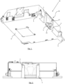
- FIG. 1 shows a shield 10 according to the invention in place over a vent V to an ECU housing H. Behind the vent V, a cooling fan unit will be located and, further internally, a PCB/processor/component to be cooled.
- the precise function of the ECU is not critical to the invention, however, a particular application is for an ECU in the automotive field, such as within direct neighbourhood of an HVAC system in a vehicle where condensation is known to develop.
- shield 10 provides a protective outer wall 11 that serves as a hood/shroud over the openings of vent V such that any fluids dropping or spraying from a direction D above and/or to the side of the housing H will be prevented from entering said housing H.
- the only access to vent V is via a side/underneath opening/airflow outlet 12 of shield 10, which is effectively a downwards facing (upwardly accessed) opening for diverting airflow from, or into, the vent V transversely/downwardly from naturally lateral direction that would be motivated by the fan within.
- housing H is fixed against a mounting surface (not shown), e.g. by fixing brackets F, it will be apparent that only a narrow clearance would be available between that surface and the outlet 12, further minimising the opportunity for fluid to enter vent V.
- Figures 3 and 4 show side and front elevation section views respectively. Particularly, Figure 3 shows a cross section of a supporting bracket S at either side of the vent V that may slidably receive a side edge 13 of shield 10. As seen in Figures 1 and 2 , brackets S provide channels for edges of the shield 13 to slide into.
- edges 13 slide from above into channels/tracks S and engage, at a distal end, via a bifurcated slot 14 with a locating feature R. Edges 13 also include ridges 15 that serve to engage and lock, via an interference fit, within a wall of channel S.
- Figure 4 shows a view where the vent V is clearly visible through the shield 10 because the outer protective wall 11 is cutaway for convenience of illustration.
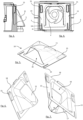
- Figures 5 to 7 show various perspective views of the shield alone so the structure of the embodiment is clear.
- Figure 7 best shows a first opening or interfacing side 16 of the shield 10 for interfacing with a fan-cooled unit and/or vent V in a housing H.
- Interfacing opening 16 is wide and generally corresponds to the outer dimensions of vent V so that airflow therethrough is not impeded.
- opening 16 is framed by side edges 13, a lower optional edge 17 and an upper edge 18 which in use, along with side edges 13, is sealed against the housing to prevent ingress of fluid through said edges.
- Figure 5 best shows the opening for airflow in use, i.e. mouth or outlet 12 transverse to and communicating with the first open side 16.
- outlet 12 is for diverting airflow from the fan-cooled unit exiting housing H through vent V.
- the external, outwardly projecting, wall 11 of the shield 10 is contoured in a tapered configuration and, in use, adapted to substantially cover the vent V, for mitigating ingress of fluid not travelling in the direction of open mouth 12; which is to say most/all fluid expected during normal use will not have an opportunity to enter housing H via vent V.
- wall 11 is contoured to generally taper outwardly from the upper edge 18, against housing H, toward the mouth 12 which is wide so as not to impede airflow.
- Many contoured or otherwise profiled shapes are possible dependent on the application, however, it is noteworthy that the maximum height of wall 11, at mouth 12, relative to frame edge 17 (see Figure 7 dimension M) is preferably limited by the footprint of housing H. That is to say, referring to Figure 1 , the lip of wall 11 at outlet 12 preferably does not extend far beyond, say, the extent of mounting brackets F. In this way, if housing H is required to slot through a tight-fitting arrangement during assembly, shield 10 will not interfere/conflict with other components or structures.
- shield 10 may be pressed/stamped from sheet metal or similar, from a blank that incorporates slots 14 and a slot opening that is drawn to form outlet 12, along with ridge formations 15.
- Various forms of the invention may feature alternative, not-illustrated, fastening elements and mechanisms, such as screws, adhesive, clips, snap-fit arrangements and the like.
- the shield may be supplied as a set of multiple shields with a range of dimensions or fastening formations to be attached to a housing specification as needed.
- a housing H fitted with a shield 10 according to the invention is ready for testing against ingress of water according to standardised methods for IPx protection, such as where a water jet or shower/splash is aimed at the housing from above where the risk of water occurs (e.g. against the roof of a horizontally positioned housing H as in Figure 1 ) and the housing or jet is tilted by up to 15 degrees in four directions from vertical during the test. It will be appreciated that a water jet would have to be aimed at the housing at greater than 90 degrees from vertical before water ingress is likely. Such scenarios are highly unlikely in the use situation envisaged for the invention, such as nearby/below an HVAC system where moisture may be present, but the direction of water droplets, etc. are predictable.
- the invention enables a method of mitigating ingress of fluid through a vent in a housing of an ECU, e.g. in a vehicle.
- the method involves the following exemplary steps: determining a fixing orientation of the housing relative to an expected source of fluid, e.g. nearby/under an HVAC unit; providing a protective cover having an outwardly projecting profile wall and an opening; positioning the protective cover over the vent so that the opening faces away from the expected source of fluid such that, in use, the outwardly projecting profile wall deflects the source of fluid.
- the shield will likely be positioned onto the housing before it is fixed in place for use, i.e. the fixing orientation takes into account where the shield is located and the direction its protective opening is facing.
- a shield for covering a vent or cooling-fan opening in a housing for electronic components.
- the shield includes an outwardly projecting wall for substantially covering the vent, while leaving a cavity for airflow, and interfaces with the housing at its edges (13) to hold it in place.
- An opening/outlet in the shield serves to divert airflow to or from the vent or fan-cooled opening while ingress of fluid is mitigated by the outwardly projectable wall, i.e. when aimed from a direction above the housing.
Landscapes
- Engineering & Computer Science (AREA)
- Microelectronics & Electronic Packaging (AREA)
- Physics & Mathematics (AREA)
- Thermal Sciences (AREA)
- Cooling Or The Like Of Electrical Apparatus (AREA)
- Theoretical Computer Science (AREA)
- Human Computer Interaction (AREA)
- General Engineering & Computer Science (AREA)
- General Physics & Mathematics (AREA)
Abstract
Description
- The present disclosure relates to a shield for fan-cooled units, e.g. an environmental shield that prevents water from entering an electronic control unit (ECU) during use and testing.
- Electronic components and computer processors are known to generate heat during use, which can result in reduced performance and failure if not addressed. Common solutions for reducing the heat load of a component include heat sinks, heat spreaders and fan-cooling.
- A fan-cooling unit is a device for transferring heat which locates a high rpm fan close to a processor or like component and either blows cool air onto or draws hot air away from it during use. Cooling is enabled by air movement where hot air in the proximity of the component surface is replaced by cooler air.
- Fan units are practical solutions, but they typically require some form of vent to enable an air flow path between inside and outside the housing within which the component is located. Such a vent may be in the form of a grill or multi-apertured structure which prevents relatively large solid objects from passing through it, while permitting air or other fluid through to circulate for the purposes of cooling. The fan itself is normally located on the internal side of the vent within the housing so it is protected from external objects and damage. The fan direction is generally configured to expel hot air from the housing, so as to avoid dust/moisture being drawn into the vent.
- It will be appreciated that while external solid objects should be prevented from access to the inside of the housing and its components, so too should some fluids such as water from condensation, rain, leakage, etc. While the rotating fan itself may provide some amount of water repulsion outwardly from the unit, it is generally impractical to provide a vent that is impervious to water, while also enabling air flow sufficient for heat exchange purposes. The contents of the unit are particularly vulnerable when powered down and the fan is off.
- It is known to test electronic devices for compliance with standards, such as IPx where the device can be certified resistant to water at the splash level, i.e. it can survive minor water splashes, droplets or even showers although it is not designed to be submerged.
- The present disclosure seeks to address issues with conventional solutions or at least provide an alternative to the public and manufacturers of electronic devices.
- According to a first aspect, a shield for a vent in a housing for electronic components is provided according to claim 1. The shield may comprise: an interfacing side for interfacing with the vent and/or fan-cooled unit in the housing; an opening configured for communicating with the interfacing side which, in use, diverts airflow to or from the vent or fan-cooled unit in use. An external wall, opposite the interfacing side, substantially shields the vent and/or fan-cooled unit in the housing, such that ingress of fluid from directions not toward with the opening is mitigated. The shield herein may alternatively termed or function as a protective cover, hood, shroud, enclosure, manifold, cowling, etc. relative to a vent opening for the purpose of minimising liquid ingress thereinto during use and testing. At the same time, air from the fan unit is relatively unimpeded to perform its cooling function, by having an outlet or inlet path through the opening.
- Alternatively, the invention can be expressed as a shield for a vent or cooling-fan unit in a housing for electronic components, comprising: an outwardly projectable wall for substantially covering the vent or cooling-fan unit and, at edges of the wall, interfacing with the housing; and an opening for communicating with the vent or cooling-fan unit to, in use, divert airflow to or from the vent or fan-cooled unit while ingress of fluid from a direction not into the opening is mitigated by the outwardly projectable wall. In practice, the edges of the wall interface/ contact with the housing about the vent on at least three sides, e.g. upper, left and right sides, creating a seal therewith. The lower side comprises the opening, although it too may have a contact edge with the housing.
- In embodiments, the wall is contoured, i.e. contoured to project outwardly relative to the housing/vent. The contour may be narrow opposite to the opening and widen toward the opening. Broadly, the surface of the wall may be tapered to gradually widen toward the outlet opening. A generally wide cross section should be maintained so as not to inhibit cooling airflow.
- As a consequence of the invention, the problem of water droplets forming/falling in the proximity of a fanunit or vent opening in a housing associated with electronic components, such as an ECU, is mitigated. Specifically, the shield acts to deflect droplets directed (e.g. by falling under gravity or in a spray/shower) from above or at an angle toward/into the fan unit/vent from entering said vent. At the same time, airflow is maintained through the opening which is positioned to face a direction least vulnerable to liquid ingress (i.e. opposite to the most common/expected direction of droplets falling under gravity or in a spray/shower). By way of example, in general terms the shield should be configured to prevent water droplet/shower ingress travelling in a downward direction or at least if the housing is tilted by up to fifteen degrees in any direction from horizontal, assuming the vent is located on a vertical side edge of the housing. The invention provides a shielding element for countering any angle of attack of a water droplet/shower/jet toward the vent, unless it is directly pointed at the opening. It is less effective if water comes "up and under" the shield through the open outlet, however, it will be appreciated that it is generally possible to predict from which angle unwanted moisture is likely to approach the housing.
- In embodiments, the shield may comprise interfacing features for coupling to a vent opening/fan unit by permanent or removable means. For example, an edge of the wall/interfacing side may be configured to slide into a channel provided in the ECU housing, proximate a vent. Multiple fixture possibilities and surface features such as holes (for screws), profiles/ridges (for interference fit into a channel) or clip mechanisms may be employed to secure the shield in place. Preferably, abutting edges of the interfacing side of the wall will be sealed with the housing or its interfacing features to prevent ingress of liquid at that edge.
- In embodiments, the shield may be pressed from sheet metal. In other forms, the shield may be moulded from plastics, e.g. by thermoforming, vacuum forming, injection moulding, etc. In embodiments, the shield may be overmouled with the housing.
- In a second broad aspect, the invention envisages a combination of the shield as described above with an ECU housing which is configured to receive the shield at an interface thereof. In one form, a maximum dimension of the shield's external surface should not exceed a footprint of the ECU housing. In this way, installation of the ECU is not inhibited by the shield excessively protruding from one side thereof. For example, the ECU may have protruding brackets/mounting structures, and the shield should not extend substantially beyond such structures.
- In embodiments, the shield may be provided as a set of shields of differing dimensions that may be selected according to the housing to which it is to be attached, e.g. according to available space for installation.
- A second aspect of the invention is embodied by a method according to
claim 14. - Illustrative embodiments will now be described with reference to the accompanying drawings in which:
-
Figure 1 illustrates an overview of a shield according to the invention in place over a cooling vent of a housing for an electronic control unit; -
Figure 2 illustrates a front elevation view of the housing fromFigure 1 ; -
Figure 3 illustrates a side elevation, partial cross section, view of the shield in place at a cooling vent of the housing; -
Figure 4 illustrates a front elevation, partial cross section, view of the shield in place at a cooling vent of the housing; -
Figure 5 illustrates a frontal overview from a low angle of the shield; -
Figure 6 illustrates a frontal overview from a high angle of the shield; and -
Figure 7 illustrates a rear overview from a low angle of the shield. - The following description presents exemplary embodiments and, together with the drawings, serves to explain principles of the invention. However, the scope of the invention is not intended to be limited to the precise details of the embodiments or exact adherence with all system features and/or method steps, since variations will be apparent to a skilled person and are deemed also to be covered by the description. Terms for components used herein should be given a broad interpretation that also encompasses equivalent functions and features.
- In some cases, several alternative terms (synonyms) for structural, system features have been provided but such terms are not intended to be exhaustive. For the avoidance of doubt, any terms separated by the "/" symbol generally refer to alternative "or" expressions where the terms can be used interchangeably. Descriptive terms should also be given the broadest possible interpretation; e.g. the term "comprising" as used in this specification means "consisting at least in part of" such that interpreting each statement in this specification that includes the term "comprising", features other than that or those prefaced by the term may also be present. Related terms such as "comprise" and "comprises" are to be interpreted in the same manner. Any directional terms such as "vertical", "horizontal", "up", "down", "sideways", "upper" and "lower" are used for convenience of explanation usually with reference to the form shown in illustrations and are not intended to be ultimately limiting if an equivalent function can be achieved with an alternative dimension and/or direction. All directional terms are relative to each other.
- The description herein refers to embodiments with particular combinations of steps or features, however, it is envisaged that further combinations and crosscombinations of compatible steps or features between embodiments will be possible. Indeed, isolated features may function independently as an invention from other features and not necessarily require implementation as a complete combination.
- It will be understood that the illustrated embodiments show applications only for the purposes of explanation. In practice, the invention may be applied to many different configurations, where the embodiment is straightforward for those skilled in the art to implement.
-
Figure 1 shows ashield 10 according to the invention in place over a vent V to an ECU housing H. Behind the vent V, a cooling fan unit will be located and, further internally, a PCB/processor/component to be cooled. The precise function of the ECU is not critical to the invention, however, a particular application is for an ECU in the automotive field, such as within direct neighbourhood of an HVAC system in a vehicle where condensation is known to develop. - It will be apparent from
Figure 1 thatshield 10 provides a protectiveouter wall 11 that serves as a hood/shroud over the openings of vent V such that any fluids dropping or spraying from a direction D above and/or to the side of the housing H will be prevented from entering said housing H. The only access to vent V is via a side/underneath opening/airflow outlet 12 ofshield 10, which is effectively a downwards facing (upwardly accessed) opening for diverting airflow from, or into, the vent V transversely/downwardly from naturally lateral direction that would be motivated by the fan within. - If/when housing H is fixed against a mounting surface (not shown), e.g. by fixing brackets F, it will be apparent that only a narrow clearance would be available between that surface and the
outlet 12, further minimising the opportunity for fluid to enter vent V. -
Figures 3 and 4 show side and front elevation section views respectively. Particularly,Figure 3 shows a cross section of a supporting bracket S at either side of the vent V that may slidably receive aside edge 13 ofshield 10. As seen inFigures 1 and 2 , brackets S provide channels for edges of theshield 13 to slide into. - In the illustrated form, edges 13 slide from above into channels/tracks S and engage, at a distal end, via a
bifurcated slot 14 with a locatingfeature R. Edges 13 also includeridges 15 that serve to engage and lock, via an interference fit, within a wall of channel S. For the avoidance of doubt,Figure 4 shows a view where the vent V is clearly visible through theshield 10 because the outerprotective wall 11 is cutaway for convenience of illustration. -
Figures 5 to 7 show various perspective views of the shield alone so the structure of the embodiment is clear. For example,Figure 7 best shows a first opening or interfacingside 16 of theshield 10 for interfacing with a fan-cooled unit and/or vent V in a housingH. Interfacing opening 16 is wide and generally corresponds to the outer dimensions of vent V so that airflow therethrough is not impeded. Notably, opening 16 is framed byside edges 13, a loweroptional edge 17 and anupper edge 18 which in use, along with side edges 13, is sealed against the housing to prevent ingress of fluid through said edges. -
Figure 5 best shows the opening for airflow in use, i.e. mouth oroutlet 12 transverse to and communicating with the firstopen side 16. In use,outlet 12 is for diverting airflow from the fan-cooled unit exiting housing H through vent V. As best seen inFigure 6 , the external, outwardly projecting,wall 11 of theshield 10 is contoured in a tapered configuration and, in use, adapted to substantially cover the vent V, for mitigating ingress of fluid not travelling in the direction ofopen mouth 12; which is to say most/all fluid expected during normal use will not have an opportunity to enter housing H via vent V. - In the illustrated form,
wall 11 is contoured to generally taper outwardly from theupper edge 18, against housing H, toward themouth 12 which is wide so as not to impede airflow. Many contoured or otherwise profiled shapes are possible dependent on the application, however, it is noteworthy that the maximum height ofwall 11, atmouth 12, relative to frame edge 17 (seeFigure 7 dimension M) is preferably limited by the footprint of housing H. That is to say, referring toFigure 1 , the lip ofwall 11 atoutlet 12 preferably does not extend far beyond, say, the extent of mounting brackets F. In this way, if housing H is required to slot through a tight-fitting arrangement during assembly, shield 10 will not interfere/conflict with other components or structures. - In the illustrated form, shield 10 may be pressed/stamped from sheet metal or similar, from a blank that incorporates
slots 14 and a slot opening that is drawn to formoutlet 12, along withridge formations 15. - Various forms of the invention may feature alternative, not-illustrated, fastening elements and mechanisms, such as screws, adhesive, clips, snap-fit arrangements and the like.
- The shield may be supplied as a set of multiple shields with a range of dimensions or fastening formations to be attached to a housing specification as needed.
- A housing H fitted with a
shield 10 according to the invention is ready for testing against ingress of water according to standardised methods for IPx protection, such as where a water jet or shower/splash is aimed at the housing from above where the risk of water occurs (e.g. against the roof of a horizontally positioned housing H as inFigure 1 ) and the housing or jet is tilted by up to 15 degrees in four directions from vertical during the test. It will be appreciated that a water jet would have to be aimed at the housing at greater than 90 degrees from vertical before water ingress is likely. Such scenarios are highly unlikely in the use situation envisaged for the invention, such as nearby/below an HVAC system where moisture may be present, but the direction of water droplets, etc. are predictable. - The invention enables a method of mitigating ingress of fluid through a vent in a housing of an ECU, e.g. in a vehicle. The method involves the following exemplary steps: determining a fixing orientation of the housing relative to an expected source of fluid, e.g. nearby/under an HVAC unit; providing a protective cover having an outwardly projecting profile wall and an opening; positioning the protective cover over the vent so that the opening faces away from the expected source of fluid such that, in use, the outwardly projecting profile wall deflects the source of fluid. In practice the shield will likely be positioned onto the housing before it is fixed in place for use, i.e. the fixing orientation takes into account where the shield is located and the direction its protective opening is facing.
- By way of summary, a shield is described herein for covering a vent or cooling-fan opening in a housing for electronic components. The shield includes an outwardly projecting wall for substantially covering the vent, while leaving a cavity for airflow, and interfaces with the housing at its edges (13) to hold it in place. An opening/outlet in the shield serves to divert airflow to or from the vent or fan-cooled opening while ingress of fluid is mitigated by the outwardly projectable wall, i.e. when aimed from a direction above the housing.
Claims (15)
- A shield for a vent or cooling-fan opening in a housing for electronic components, the shield comprising:an outwardly projectable wall for substantially covering the vent or cooling-fan opening and, at edges of the wall, interfacing with the housing; andan opening for communicating with the vent or cooling-fan unit to, in use, divert airflow to or from the vent or fan-cooled opening while ingress of fluid is mitigated by the outwardly projectable wall.
- The shield according to claim 1, wherein edges of the wall are configured to contact with the housing about the vent on at least two sides for sealing therewith.
- The shield according to claim 2, wherein at least one of the edges comprises an interfacing feature for removably coupling to the housing or vent.
- The shield according to claim 3, wherein the interfacing feature is configured to cooperate with a channel provided in the housing.
- The shield according to claim 3 or 4, wherein the interfacing feature includes surface features selected from at least one of: holes, profiles, ridges, clip.
- The shield according to any preceding claim, wherein the wall is contoured, configuring the shield to project outwardly relative to the housing/vent.
- The shield according to claim 6, wherein the contour is profiled to taper from a narrow end, opposite to the opening, and widen toward the opening.
- The shield according to any preceding claim, pressed from sheet metal.
- An ECU housing configured to mount the shield according to any preceding claim, over a vent for a fan unit thereof.
- The ECU housing of claim 9, comprising a coupling feature for receiving edges of the shield wall.
- The ECU housing of claim 9, wherein the shield is overmoulded to the housing.
- The ECU housing of any preceding claim 9 to 11, wherein an outwardly projecting dimension of the wall is adapted to be within a footprint of the ECU housing.
- The ECU housing of claim 10, wherein a set of shields is provided, with a range of dimensions, to be selected for attachment to the coupling feature.
- A method of mitigating ingress of fluid through a vent in a housing of an ECU, comprising:determining a fixing orientation of the housing relative to an expected source of fluid;providing a protective cover having an outwardly projecting profile wall and an opening;positioning the protective cover over the vent so that the opening faces away from the expected source of fluid and, in use, the outwardly projecting profile wall deflects the source of fluid.
- The method of claim 14, wherein the housing is fixed into a vehicle.
Priority Applications (3)
| Application Number | Priority Date | Filing Date | Title |
|---|---|---|---|
| EP23165666.1A EP4440254A1 (en) | 2023-03-30 | 2023-03-30 | Shield for fan-cooled units |
| CN202410332866.6A CN118741906A (en) | 2023-03-30 | 2024-03-22 | Protective cover for fan cooling unit |
| US18/616,360 US20240329702A1 (en) | 2023-03-30 | 2024-03-26 | Shield For Fan-Cooled Units |
Applications Claiming Priority (1)
| Application Number | Priority Date | Filing Date | Title |
|---|---|---|---|
| EP23165666.1A EP4440254A1 (en) | 2023-03-30 | 2023-03-30 | Shield for fan-cooled units |
Publications (1)
| Publication Number | Publication Date |
|---|---|
| EP4440254A1 true EP4440254A1 (en) | 2024-10-02 |
Family
ID=85792027
Family Applications (1)
| Application Number | Title | Priority Date | Filing Date |
|---|---|---|---|
| EP23165666.1A Pending EP4440254A1 (en) | 2023-03-30 | 2023-03-30 | Shield for fan-cooled units |
Country Status (3)
| Country | Link |
|---|---|
| US (1) | US20240329702A1 (en) |
| EP (1) | EP4440254A1 (en) |
| CN (1) | CN118741906A (en) |
Citations (6)
| Publication number | Priority date | Publication date | Assignee | Title |
|---|---|---|---|---|
| JPH06327121A (en) * | 1993-05-10 | 1994-11-25 | Yazaki Corp | Electrical junction box |
| JP2002118925A (en) * | 2000-10-11 | 2002-04-19 | Suzuki Motor Corp | Waterproof controller |
| US20040057209A1 (en) * | 2002-09-24 | 2004-03-25 | I-Huei Huang | Heat dissipation apparatus |
| CN202285471U (en) * | 2011-10-26 | 2012-06-27 | 中国北车股份有限公司大连电力牵引研发中心 | Ventilated rain-proof cabinet body |
| JP2018188974A (en) * | 2017-04-28 | 2018-11-29 | いすゞ自動車株式会社 | Cover structure of control unit |
| CN213007982U (en) * | 2020-08-27 | 2021-04-20 | 长沙海韵汽车零部件有限公司 | Automobile ECU waterproof cover |
Family Cites Families (6)
| Publication number | Priority date | Publication date | Assignee | Title |
|---|---|---|---|---|
| US6930882B2 (en) * | 2003-04-07 | 2005-08-16 | Dell Products L.P. | Processor shroud adaptor for multiple CPU locations |
| US20050237716A1 (en) * | 2004-04-21 | 2005-10-27 | International Business Machines Corporation | Air flow system and method for facilitating cooling of stacked electronics components |
| US8009430B2 (en) * | 2007-05-17 | 2011-08-30 | International Business Machines Corporation | Techniques for data center cooling |
| US20130088833A1 (en) * | 2011-10-05 | 2013-04-11 | International Business Machines Corporation | Flexible air duct for equipment cooling |
| FR3086891B1 (en) * | 2018-10-03 | 2020-12-18 | Valeo Systemes Thermiques | ELECTRONIC COMPONENT FOR MOTOR VEHICLES |
| US11907029B2 (en) * | 2019-05-15 | 2024-02-20 | Upstream Data Inc. | Portable blockchain mining system and methods of use |
-
2023
- 2023-03-30 EP EP23165666.1A patent/EP4440254A1/en active Pending
-
2024
- 2024-03-22 CN CN202410332866.6A patent/CN118741906A/en active Pending
- 2024-03-26 US US18/616,360 patent/US20240329702A1/en active Pending
Patent Citations (6)
| Publication number | Priority date | Publication date | Assignee | Title |
|---|---|---|---|---|
| JPH06327121A (en) * | 1993-05-10 | 1994-11-25 | Yazaki Corp | Electrical junction box |
| JP2002118925A (en) * | 2000-10-11 | 2002-04-19 | Suzuki Motor Corp | Waterproof controller |
| US20040057209A1 (en) * | 2002-09-24 | 2004-03-25 | I-Huei Huang | Heat dissipation apparatus |
| CN202285471U (en) * | 2011-10-26 | 2012-06-27 | 中国北车股份有限公司大连电力牵引研发中心 | Ventilated rain-proof cabinet body |
| JP2018188974A (en) * | 2017-04-28 | 2018-11-29 | いすゞ自動車株式会社 | Cover structure of control unit |
| CN213007982U (en) * | 2020-08-27 | 2021-04-20 | 长沙海韵汽车零部件有限公司 | Automobile ECU waterproof cover |
Also Published As
| Publication number | Publication date |
|---|---|
| CN118741906A (en) | 2024-10-01 |
| US20240329702A1 (en) | 2024-10-03 |
Similar Documents
| Publication | Publication Date | Title |
|---|---|---|
| CN107787141B (en) | Housing for an electronic device comprising an air outlet with fluid penetration mitigation | |
| US5725622A (en) | Hood for use on Avionic line replaceable unit | |
| CN107366986B (en) | Baffle structure, electric control box, air conditioner outdoor unit and air conditioner | |
| EP2887786B1 (en) | Universal inlet duct system for side air intake equipment | |
| CN205812602U (en) | Anti-spraying protection device, cooling air system and electrically or electronically device | |
| EP2416638A2 (en) | Electronic Device | |
| CN107791826B (en) | Shield for heat dissipation assembly of vehicle and heat dissipation assembly | |
| US20240329702A1 (en) | Shield For Fan-Cooled Units | |
| CN211261046U (en) | Electric control box and window type air conditioner | |
| US12302539B2 (en) | Electronic device with active cooling | |
| CN114537292B (en) | Vehicle Camera Mounting Kit | |
| CN112684862B (en) | Air guiding device and server | |
| JP2008296853A (en) | Automobile intake duct structure | |
| CN112856002A (en) | Air flue waterproof structure, pressure release valve and vehicle | |
| JP2000294965A (en) | Electronic equipment cooling device | |
| CN214792119U (en) | Heat dissipation system and refrigerator | |
| CN210641167U (en) | Automatically controlled box subassembly and air condensing units | |
| CN212538075U (en) | Waterproof installation device and air conditioner | |
| JPH0534977Y2 (en) | ||
| CN223624790U (en) | A reactor protection structure and a heat pump | |
| US9776472B2 (en) | Body vent protector | |
| JP3102206B2 (en) | Bathroom TV cooling system | |
| CN110878968A (en) | Air conditioner indoor unit with hidden human sensing device | |
| EP3859132B1 (en) | Fan guide unit | |
| CN215774056U (en) | Automatically controlled box waterproof construction and integral air conditioner |
Legal Events
| Date | Code | Title | Description |
|---|---|---|---|
| PUAI | Public reference made under article 153(3) epc to a published international application that has entered the european phase |
Free format text: ORIGINAL CODE: 0009012 |
|
| STAA | Information on the status of an ep patent application or granted ep patent |
Free format text: STATUS: THE APPLICATION HAS BEEN PUBLISHED |
|
| AK | Designated contracting states |
Kind code of ref document: A1 Designated state(s): AL AT BE BG CH CY CZ DE DK EE ES FI FR GB GR HR HU IE IS IT LI LT LU LV MC ME MK MT NL NO PL PT RO RS SE SI SK SM TR |
|
| STAA | Information on the status of an ep patent application or granted ep patent |
Free format text: STATUS: REQUEST FOR EXAMINATION WAS MADE |
|
| 17P | Request for examination filed |
Effective date: 20241024 |
|
| RBV | Designated contracting states (corrected) |
Designated state(s): AL AT BE BG CH CY CZ DE DK EE ES FI FR GB GR HR HU IE IS IT LI LT LU LV MC ME MK MT NL NO PL PT RO RS SE SI SK SM TR |
|
| GRAP | Despatch of communication of intention to grant a patent |
Free format text: ORIGINAL CODE: EPIDOSNIGR1 |
|
| STAA | Information on the status of an ep patent application or granted ep patent |
Free format text: STATUS: GRANT OF PATENT IS INTENDED |