EP4440155A1 - Acqusition sequences of binaural hearing systems comprising hearing implants - Google Patents
Acqusition sequences of binaural hearing systems comprising hearing implants Download PDFInfo
- Publication number
- EP4440155A1 EP4440155A1 EP23165779.2A EP23165779A EP4440155A1 EP 4440155 A1 EP4440155 A1 EP 4440155A1 EP 23165779 A EP23165779 A EP 23165779A EP 4440155 A1 EP4440155 A1 EP 4440155A1
- Authority
- EP
- European Patent Office
- Prior art keywords
- processing unit
- hearing
- wireless communication
- hearing device
- implant
- Prior art date
- Legal status (The legal status is an assumption and is not a legal conclusion. Google has not performed a legal analysis and makes no representation as to the accuracy of the status listed.)
- Pending
Links
Images




Classifications
-
- H—ELECTRICITY
- H04—ELECTRIC COMMUNICATION TECHNIQUE
- H04R—LOUDSPEAKERS, MICROPHONES, GRAMOPHONE PICK-UPS OR LIKE ACOUSTIC ELECTROMECHANICAL TRANSDUCERS; ELECTRIC HEARING AIDS; PUBLIC ADDRESS SYSTEMS
- H04R25/00—Electric hearing aids
- H04R25/55—Electric hearing aids using an external connection, either wireless or wired
- H04R25/552—Binaural
-
- H—ELECTRICITY
- H04—ELECTRIC COMMUNICATION TECHNIQUE
- H04B—TRANSMISSION
- H04B5/00—Near-field transmission systems, e.g. inductive or capacitive transmission systems
- H04B5/70—Near-field transmission systems, e.g. inductive or capacitive transmission systems specially adapted for specific purposes
- H04B5/79—Near-field transmission systems, e.g. inductive or capacitive transmission systems specially adapted for specific purposes for data transfer in combination with power transfer
-
- H—ELECTRICITY
- H04—ELECTRIC COMMUNICATION TECHNIQUE
- H04L—TRANSMISSION OF DIGITAL INFORMATION, e.g. TELEGRAPHIC COMMUNICATION
- H04L65/00—Network arrangements, protocols or services for supporting real-time applications in data packet communication
- H04L65/10—Architectures or entities
- H04L65/1059—End-user terminal functionalities specially adapted for real-time communication
-
- H—ELECTRICITY
- H04—ELECTRIC COMMUNICATION TECHNIQUE
- H04L—TRANSMISSION OF DIGITAL INFORMATION, e.g. TELEGRAPHIC COMMUNICATION
- H04L65/00—Network arrangements, protocols or services for supporting real-time applications in data packet communication
- H04L65/60—Network streaming of media packets
- H04L65/70—Media network packetisation
-
- H—ELECTRICITY
- H04—ELECTRIC COMMUNICATION TECHNIQUE
- H04L—TRANSMISSION OF DIGITAL INFORMATION, e.g. TELEGRAPHIC COMMUNICATION
- H04L65/00—Network arrangements, protocols or services for supporting real-time applications in data packet communication
- H04L65/80—Responding to QoS
-
- H—ELECTRICITY
- H04—ELECTRIC COMMUNICATION TECHNIQUE
- H04R—LOUDSPEAKERS, MICROPHONES, GRAMOPHONE PICK-UPS OR LIKE ACOUSTIC ELECTROMECHANICAL TRANSDUCERS; ELECTRIC HEARING AIDS; PUBLIC ADDRESS SYSTEMS
- H04R25/00—Electric hearing aids
- H04R25/55—Electric hearing aids using an external connection, either wireless or wired
- H04R25/554—Electric hearing aids using an external connection, either wireless or wired using a wireless connection, e.g. between microphone and amplifier or using Tcoils
-
- H—ELECTRICITY
- H04—ELECTRIC COMMUNICATION TECHNIQUE
- H04W—WIRELESS COMMUNICATION NETWORKS
- H04W4/00—Services specially adapted for wireless communication networks; Facilities therefor
- H04W4/80—Services using short range communication, e.g. near-field communication [NFC], radio-frequency identification [RFID] or low energy communication
-
- A—HUMAN NECESSITIES
- A61—MEDICAL OR VETERINARY SCIENCE; HYGIENE
- A61N—ELECTROTHERAPY; MAGNETOTHERAPY; RADIATION THERAPY; ULTRASOUND THERAPY
- A61N1/00—Electrotherapy; Circuits therefor
- A61N1/18—Applying electric currents by contact electrodes
- A61N1/32—Applying electric currents by contact electrodes alternating or intermittent currents
- A61N1/36—Applying electric currents by contact electrodes alternating or intermittent currents for stimulation
- A61N1/36036—Applying electric currents by contact electrodes alternating or intermittent currents for stimulation of the outer, middle or inner ear
- A61N1/36038—Cochlear stimulation
-
- A—HUMAN NECESSITIES
- A61—MEDICAL OR VETERINARY SCIENCE; HYGIENE
- A61N—ELECTROTHERAPY; MAGNETOTHERAPY; RADIATION THERAPY; ULTRASOUND THERAPY
- A61N1/00—Electrotherapy; Circuits therefor
- A61N1/18—Applying electric currents by contact electrodes
- A61N1/32—Applying electric currents by contact electrodes alternating or intermittent currents
- A61N1/36—Applying electric currents by contact electrodes alternating or intermittent currents for stimulation
- A61N1/372—Arrangements in connection with the implantation of stimulators
- A61N1/37211—Means for communicating with stimulators
- A61N1/37217—Means for communicating with stimulators characterised by the communication link, e.g. acoustic or tactile
- A61N1/37223—Circuits for electromagnetic coupling
-
- A—HUMAN NECESSITIES
- A61—MEDICAL OR VETERINARY SCIENCE; HYGIENE
- A61N—ELECTROTHERAPY; MAGNETOTHERAPY; RADIATION THERAPY; ULTRASOUND THERAPY
- A61N1/00—Electrotherapy; Circuits therefor
- A61N1/18—Applying electric currents by contact electrodes
- A61N1/32—Applying electric currents by contact electrodes alternating or intermittent currents
- A61N1/36—Applying electric currents by contact electrodes alternating or intermittent currents for stimulation
- A61N1/372—Arrangements in connection with the implantation of stimulators
- A61N1/37211—Means for communicating with stimulators
- A61N1/37252—Details of algorithms or data aspects of communication system, e.g. handshaking, transmitting specific data or segmenting data
- A61N1/37288—Communication to several implantable medical devices within one patient
-
- H—ELECTRICITY
- H04—ELECTRIC COMMUNICATION TECHNIQUE
- H04R—LOUDSPEAKERS, MICROPHONES, GRAMOPHONE PICK-UPS OR LIKE ACOUSTIC ELECTROMECHANICAL TRANSDUCERS; ELECTRIC HEARING AIDS; PUBLIC ADDRESS SYSTEMS
- H04R2225/00—Details of deaf aids covered by H04R25/00, not provided for in any of its subgroups
- H04R2225/55—Communication between hearing aids and external devices via a network for data exchange
-
- H—ELECTRICITY
- H04—ELECTRIC COMMUNICATION TECHNIQUE
- H04R—LOUDSPEAKERS, MICROPHONES, GRAMOPHONE PICK-UPS OR LIKE ACOUSTIC ELECTROMECHANICAL TRANSDUCERS; ELECTRIC HEARING AIDS; PUBLIC ADDRESS SYSTEMS
- H04R2225/00—Details of deaf aids covered by H04R25/00, not provided for in any of its subgroups
- H04R2225/67—Implantable hearing aids or parts thereof not covered by H04R25/606
Definitions
- the present disclosure relates to acquisition sequences of binaural hearing systems and corresponding binaural hearing systems.
- the binaural hearing systems may comprise first and second hearing devices, for example head-wearable devices at a user's ears, and first and second hearing implants.
- Binaural hearing systems that comprise a pair of hearing implants may comprise at least four separate devices that are wirelessly connected via at least three bidirectional wireless communication links during normal operation.
- a first bidirectional wireless communication link must be connected between a first hearing device, typically arranged at, in or on a user's ear, and a first hearing implant such as a cochlea implant.
- a second bidirectional wireless communication link must be connected between a second hearing device, typically arranged at, in or on the user's opposite ear, and a second hearing implant.
- a third bidirectional wireless communication link must be connected between the first and second hearing devices, i.e. a bilateral link, to allow the devices at opposite sides of the user's head to communicate data for example digital audio signals to enable sophisticated binaural processing algorithms and/or synchronize other functions of the first and second hearing devices.
- a hearing systems that for example use a common communication protocol between devices and implants, and support rapid and energy efficient acquisition of each of the first and second bidirectional wireless communication links as well as the bilateral link at start-up of the binaural hearing system.
- energy efficient operation of the first and second hearing devices and the first and second hearing implants during normal operation of the binaural hearing system.
- Each of the first and second hearing devices and the first and second hearing implants is typically a relatively small device energized by power sources with limited capacity like rechargeable batteries.
- a first aspect of the invention relates to a binaural hearing system comprising:
- the latter After a successful acquisition sequence of the binaural hearing system the latter preferably enters a normal operation mode where the first hearing device and the first hearing implant are wirelessly connected through the first bidirectional wireless communication link.
- the second hearing device and the second hearing implant are likewise wirelessly connected through the second bidirectional wireless communication link during normal operation.
- the first hearing device and the second hearing device are wirelessly connected through the bilateral bidirectional wireless communication link during normal operation.
- the common communication protocol may be proprietary and designed for minimal power consumption since each of the first and second hearing devices and each of the first and second hearing implants typically are relatively small battery powered devices or otherwise energized by a power source with limited capacity.
- One of the first hearing device and second hearing device is preferably configured as master and the other one as slave for the purpose of acquiring and operating the bilateral bidirectional wireless communication link using their respective first and second processing units as discussed in additional detail below with reference to the appended drawings.
- Each of the first and second hearing devices may comprise a head-wearable housing shaped and sized similarly to a traditional hearing aid for example of so-called BTE, ITE, ITC, CIC or RIC types of housings.
- the housings may be shaped and sized for placement at, or in, a user's left or right ear for example shaped and sized for placement behind the user's left and right ear pinna.
- the first and second hearing implants may be configured for placement at respective sides of the user's skull and configured to supply respective nerve stimulus signals to the user's left and right hearing nerves via implanted electrode arrays.
- Each of the first and second bidirectional wireless communication links and the bilateral bidirectional wireless communication link may be based on near-field magnetic coupling, such as NFMI, using respective magnetic coil antennas mounted in the first and second hearing devices.
- Each of the first and second bidirectional wireless communication links and the bilateral bidirectional wireless communication link may for example use a carrier frequency between 5 and 50 MHz as discussed in additional detail below with reference to the appended drawings.
- At least a subset of the first and second ipsilateral data packets comprises respective digital audio data such as real-time digital audio signals; and/or at least a subset of the bilateral data packets comprises respective digital audio data such as real-time digital audio signals as discussed in additional detail below with reference to the appended drawings.
- Each of the first processing unit and second processing unit may comprise a digital signal processor (DSP) and/or a microprocessor such as a software programmable DSP or a software programmable microprocessor.
- the software programmable DSP or microprocessor may be configured to execute plurality of program instructions configured to implement at least parts of the respective acquisitions of the first and second bidirectional wireless communication links and the bilateral bidirectional wireless communication link in accordance with the common communication protocol.
- Each of the first processing unit and second processing unit may comprise a dedicated digital state machine configured to handle certain steps of the acquisitions of the first and second bidirectional wireless communication links and the bilateral bidirectional wireless communication link in accordance with the common communication protocol.
- a "time slot” is the shortest time division of the bilateral bidirectional wireless communication link and first and second bidirectional wireless communication links as defined by the common communication protocol.
- One data packet may for example be transmitted in one time slot.
- a "frame” is a unit of data that comprises a predefined number of time slots as defined by a communication protocol.
- Connectable shall mean that the wireless communication link in question is configured to establish a wireless connection between specified devices after acquisition of the wireless communication link in question.
- a "bidirectional wireless communication link” is a wireless communication link that supports transmission of data packets or data messages from a first device to a second device and transmission of data packets or data messages from the second device to the first device.
- Ipsilateral data packets are data packets exchanged between a hearing device and a hearing implant arranged at the same side of a user's head.
- a “hearing implant” shall mean that portion of a cochlear implant that is located inside the user's skull.
- Each frame of the plurality of consecutive time frames may comprise at least four time slots such as four overlapping time slots.
- the length of each of the at least four time slots may be identical as discussed in additional detail below with reference to the appended drawings.
- each of the predetermined time steps for the sliding of the plurality of time slots is less than 5 %, for example less than 1 %, of a length of one time slot of the plurality of time slots of the frame as discussed in additional detail below with reference to the appended drawings.
- the first synchronization marker comprises a unique pair ID for pairing the first hearing device and the second hearing device
- the first synchronization marker transmitted from the first processing unit to the second processing unit during acquisition of the bilateral bidirectional wireless communication link may for example comprise a first unique pair ID.
- the second processing unit is configured to:
- the synchronization marker may at least comprise:
- the common communication protocol may comprise a plurality of super frames each comprising a plurality of individual frames, such as between 4 and 32 individual frames, of the plurality of consecutive frames.
- the second processing unit is preferably configured to determine an offset in frames between consecutive super frames,
- the acquisition sequence comprises:
- a second aspect of the invention relates to an acquisition sequence, e.g. an computer-implemented acquisition method, in accordance with the common communication protocol for acquiring respective connections between a first hearing device and a first hearing implant, a second hearing device and a second hearing implant and the first hearing device and the second hearing device.
- the acquisition sequence comprising:
- FIG. 1 schematically illustrates a first hearing device 100L and a first hearing implant 150L of an exemplary binaural hearing system 125.
- the binaural hearing system 125 further comprises a second hearing device 100L and a second hearing implant 150L both arranged at the opposite side of the user's head 250 and therefore not visible.
- the first hearing implant 150L is adapted for surgical implantation in the user's skull and therefore invisible from the outside when implanted.
- the second hearing implant 150R is arranged in a corresponding manner at the opposite side of the user's head 250.
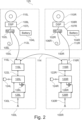
- FIG. 2 is a block diagram of the binaural hearing system 125.
- the first hearing device 100L is connectable to the first hearing implant 150L via a first bidirectional wireless communication link 112L ("first link") for exchange of first ipsilateral data packets.
- the second hearing device 100L is likewise connectable to the second hearing implant 150L via a second bidirectional wireless communication link 112L ("second link”) for exchange of second ipsilateral data packets.
- the binaural hearing system 125 further comprises a bilateral bidirectional wireless communication link 114 ("bilateral link", or "third link”) that is connectable between the first hearing device 100L and second hearing device 100R for exchange of bilateral data packets.
- the first hearing device 100L and second hearing device 100R are preferably configured to use the respective magnetic coil antennas 116L, 116R for wireless communication with the first hearing implant 150L and second hearing implant 150R, respectively.
- the bilateral link 114, first link 112L and second link 112R are preferably configured to utilize, i.e. operate in accordance with, a common data communication protocol.
- the common data communication protocol comprises a plurality of consecutive time frames that each comprises a plurality of time slots holding the first and second ipsilateral data packets and the bilateral data packets.
- the respective pluralities of first and second ipsilateral data packets and bilateral data packets are structured, transmitted and received in accordance with the common data communication protocol as discussed in further detail below.
- synchronization markers and acknowledge messages may be wirelessly transmitted between the first hearing device 100L and second hearing device 100R, between the first hearing device 100L and the first hearing implant 150L and between the second hearing device 100R second hearing implant 150R before the respective acquisitions of the bilateral link 114, first link 112L and second link 112R.
- the bilateral data packets exchanged by the bilateral link 114 may comprise digital audio samples and control information transmitted by respective ones of the first and second hearing devices 100L, 100R.
- Each of the first and second hearing devices 100L, 100R may transmit digital audio samples and control data to the first and second hearing implant 150L, 150R, respectively.
- Each of the first and second hearing implants 150L, 150R preferably utilizing the first and second control units, e.g. implant processor, 108L, 108R, respectively, may additionally be configured to transmit respective control data to the first and second hearing devices 100L, 100R via the first link 112L and second link 112R. In the latter embodiment both of the first link 112L and second link 112R are adapted for bidirectional data transfer.
- Each of the first link 112L, second link 112R and bilateral link 114 may in certain embodiments of the invention be based on, or comprise, near-field magnetic coupling, such as NFMI links.
- the first link 112L may accordingly comprise a magnetic coil antenna 116R of the first hearing device 100L and a magnetic coil antenna 102R of the first hearing implant 150L.
- the second link 112R may likewise comprise a magnetic coil antenna 116L of the second hearing device 100L and a magnetic coil antenna 102L of the second hearing implant 100L.
- Each of first link 112L, second link 112R and bilateral link 114 may for example utilize a carrier frequency between 5 MHz and 50 MHz, such as between 9 MHz and 27 MHz for transmissions of the first and second ipsilateral data packets and the bilateral data packets.
- the first hearing implant 150L comprises the first control unit 108L that is connected to the magnetic coil antenna 102L for receipt and processing of the first ipsilateral data packets transmitted by the first hearing device 100L.
- the first control unit 108L is further configured to transmit the first ipsilateral data packets to the first hearing device 100L via the first link 112L.
- a first processing unit 108L of the first hearing implant 150L may comprise a digital signal processor (DSP) and/or a microprocessor.
- DSP digital signal processor
- Certain embodiments of the first hearing implant 150L may comprise a rechargeable battery assembly 104L.
- the rechargeable battery assembly 104L is configured for receiving electrical power from a receiver (Rx) charging coil 110L during dedicated recharging operations or sessions.
- the receiver (Rx) charging coil 110L may be energized by an appropriately positioned external, i.e. outside the user's skull, transmitter (Tx) charging coil (not shown) of a charging device (not shown) during the dedicated recharging sessions. This allows wireless transfer of power to the rechargeable battery assembly 104L.
- the rechargeable battery assembly 104L is preferably coupled to a power supply input of an implant processor 108L to energize the latter as schematically indicated by a power line or wire 107L.
- the implant processor 108L may comprise a microprocessor for example software programmable microprocessor.
- the first hearing implant 150L further comprises an electrode array 106L for insertion into a cochlea of the user during implantation.
- the electrode array 106L may be electrically coupled to the first processing unit 108L that supplies suitable electrode stimuli signals to the electrode array 106L to stimulate the user's cochlea nerve.
- these electrode stimuli signals may be generated by the first processing unit 108L and derived by the latter based on the first ipsilateral data packets, in particular digital audio signals or data embedded or held in the first ipsilateral data packets.
- corresponding functions, structures and features of the second hearing implant 150R may be largely identical to those of the first hearing implant 150L.
- the block diagram on FIG. 2 further illustrates an exemplary embodiment of the first hearing device 100L.
- the first hearing device 100L comprises the magnetic coil antenna 116L which is electrically connected to a transceiver 118L.
- the transceiver 118R is configured to repeatedly switch between Tx and Rx modes to modulate and demodulate incoming and outgoing data of the first ipsilateral data packets and bilateral data packets.
- the transceiver 118L may be configured to convert the first ipsilateral data packets and bilateral data packets to a format understood by a first processing unit 120L of the first hearing device 100L.
- the first processing unit 120L may comprise a digital signal processor (DSP) and/or a microprocessor such as a software programmable DSP or a microprocessor.
- DSP digital signal processor
- the first hearing device 100L further comprises one or more microphones 124L that are coupled to an appropriate audio interface of the first processing unit 120L.
- the first processing unit 120L may be configured to execute a suitable operating system.
- the operating system may be configured to manage various hardware and software resources of the first hearing device 100L such as handling of the common communication protocol, computation of monaurally or bilaterally beamformed microphone signals, hearing loss compensation processing of the microphone signal(s), the first wireless data communication interface 118L, certain memory resources etc.
- the operating system may schedule tasks for efficient use of hearing device resources and may further include accounting software for cost allocation, including power consumption, processor time, memory locations, wireless transmissions, and other resources.
- the operating system may be stored in and retrieved from a non-volatile memory (not shown), e.g. flash memory or EEPROM, of the processing unit 120L.
- Each of the first and second hearing devices 100L, 100R may comprise a housing of a type that is well-known from the hearing aid industry like so-called BTE, ITE, ITC, CIC or RIC housing types. These housing types are shaped and sized for placement at, or in, the user's ear.
- the first hearing device 100L further comprises a system clock generator 126L that is configured to supply system clock signals to various digital logic circuits and components of the device 100L including the first processing unit 120R as schematically illustrated.
- a nominal value of a clock frequency of the system clock generator 126R may lie between 2 MHz and 64 MHz such as between 10 MHz and 50 MHz.
- the first processing unit 120R may be configured to derive respective lengths of certain time slots and time frames of the common communication protocol of the first link 112L and the bilateral link 114 as discussed in additional detail below.
- the first hearing device 100L may additionally comprises a second, optional, wireless communication interface 128L and RF antennal 130L configured to jointly communicate through a second wireless communication link (not shown).
- the second wireless communication link and interface may be configured to operate in the 2.4 GHz industrial scientific medical (ISM) band and may be compliant with a Bluetooth LE standard.
- This second wireless communication link may provide convenient data connectivity to various types of portable communication devices like smartphones, mobile phones, tablets and personal computers etc. due to the industry standard compatible nature of the second wireless communication link.
- Various types of control data and audio data may be transmitted from the portable communication device to the first hearing device 100L and vice versa.
- the second hearing device 100L may for the same purpose comprise a similar optional second wireless communication interface 128L and RF antenna 130L as illustrated.
- the first hearing device 100L of the binaural hearing system 125 is assigned as master during execution of the common communication protocol while the second hearing device 100R is configured as a slave.
- the system clock signal of the master processing unit 120L may control timing of transmissions of respective data packets through the first link 112L, second link 112R and bilateral link 114 at least after the acquisitions of the first link 112L, second link 112R and bilateral link 114.
- FIG. 3 schematically illustrates transmission of a first synchronization marker 465c from the master processing unit 120L of the first or master hearing device 100L to the second or slave hearing device 100R during acquisition of the bilateral link 114 according to embodiments of the common communication protocol of the exemplary binaural hearing system 125.
- the master processing unit 120L operates as a master device towards the second hearing device 100R.
- the master processing unit 120L may start to repeatedly transmit the first synchronization marker 465c to the second hearing device 100R. using one of a plurality of time slots, e.g. time slots 1-4, of each frame, Frame-1, Frame-2 etc., of a plurality of consecutive frames.
- the indicated time slots 1-4 are referenced to the master processing unit 120L.
- Time slot 1 at the master processing unit 120L is selected for transmission of the first synchronization marker 465c in the present example as illustrated and made in accordance with the common communication protocol.
- the second hearing device 100R resides concurrently in a receipt mode such that the second, or slave, processing unit 102R of the slave hearing device 100R monitors the bilateral link 114 to detect receipt of the first synchronization marker 465c.
- the respective time slots 1-4 at the master processing unit 120L and the first hearing implant 150L are most likely more or less unaligned or non-synchronous at the current acquisition step of the acquisition sequence caused by free-running clock generators and system clock signals at the master processing unit 120L and the slave processing unit 120R. As illustrated by FIG.
- the slave hearing device 100R searches for the first synchronization marker 465c in a time slot 471 at the slave hearing device 100R which exemplary time slot 471 is shifted or misaligned, as indicated by the S-slot-2 arrow, with about one-fourth of the length of one time slot relative to the time slots at the master processing unit 120L.
- This misalignment of time slots prevents the slave hearing device 100R from detecting the first synchronization marker 465c because the latter extends across two adjacent time slots at the slave hearing device 100R.
- the slave processing unit 120R advances or slides its time slots 1-4, such as the exemplary time slot 471, with predetermined time steps between frames of the plurality of consecutive frames using a wrap-around scheme as schematically indicated by "Time slide" arrow.
- the wrap-around scheme means that that the sliding of the time slots slave processing unit 120R, such as S-slot 2, jumps back to time slot 1 when the end of time slot 4 is reached by the sliding operation.
- the predetermined time step for the slot sliding is preferably much shorter than a length of one time slot such as less 5 % or less than 1 % of the length of one time slot to gradually align the time slots 1-4 at the slave processing unit 120R with the time slots 1-4 at the master processing unit 120L.
- the slave processing unit 120R may continue to slide its time slots 1-4 by a wrap-around scheme until the latter time slots are sufficiently aligned with the time slots 1-4 at the master processing unit 120L to detect receipt of the first synchronization marker 465c at the slave processing unit 120R.
- the slave processing unit 120R may check the unique pair ID of the received first synchronization marker to ensure it is transmitted from the paired device, i.e. the master hearing device 100L in the present situation.
- the search for the first synchronization marker 465c by the slave processing unit 120R may optionally comprise recognition of a predetermined search sequence 701 ( FIG. 7 ) as described in further detail below.
- the slave processing unit 120R may be configured to ignore the first synchronization marker 465c if it is not transmitted by the paired device, i.e. the unique pair ID of the received synchronization marker does not match that of the first synchronization marker 465c. In the latter situation slave processing unit 120R may thereafter continue the search for the first synchronization marker 465a.
- the slave processing unit 120R may respond by detecting the time slot, e.g. time slot 1, at the master processing unit 120L in which the first synchronization marker 465c was transmitted by a slot indicator bit or field of the first synchronization marker as discussed in further detail below.
- the slave processing unit 120R may, based on that time slot identification, align, i.e. synchronize, the time slots at the slave processing unit 120R with the corresponding time slots at the master processing unit 120L of the first hearing device 100L. Hence, synchronize data packet exchange or communication between the slave processing unit 120R and the master processing unit 120L through the bilateral link 114.
- the slave processing unit 120R thereafter shifts to a transmission mode and transmits an acknowledge message 470 (ACK) to the master processing unit 120L in time slot 2 at the master processing unit 120L as schematically illustrated by FIG. 3 .
- the master processing unit 120L may respond by completing or terminating the acquisition of the bilateral link 114 because the latter is now appropriately connected between the master processing unit 120 and the slave processing unit 120R in accordance with exemplary embodiments of the common communication protocol of the binaural hearing system 125.
- the master processing unit 120L and the slave processing unit 120R are accordingly ready to exchange the bilateral data packets 430, 480 using time slots 1 and 2 of the plurality of consecutive frames as illustrated by FIG. 4 .
- the master processing unit 120L transmits a first bilateral data packet 430 to the slave processing unit 120R which resides in a receipt mode or state during time slot 1.
- the slave processing unit 120R transmits a second bilateral data packet 480 to the master processing unit 120L which now has switched to a receipt mode or state during time slot 2.
- time slots may specify more than four time slots per frame such as between 5 and 16 time slots. Irrespective of the actual number of time slots, such as at least four time slots, these are preferably non-overlapping time slots.
- Each time slot may have a length between 24 ⁇ s and 384 ⁇ s for example depending a number of bits of at least some of the exchanged data packets. The length of each of the time slots may be identical.
- Each of the first ipsilateral data packets 455, 460 and the second ipsilateral data packets 405, 410 may comprise identical number of bits for example between 4 bits and 96 bits such as between 6 bits and 24 bits. The number of bits in a particular data packet may depend on content type, i.e. digital audio signals, control information or a combination of both.
- At least some of the bilateral data packets 430, 480 comprise digital audio signals and/or control information.
- the control information may be held in a packet header and the digital audio signals held in a packet payload.
- the digital audio signals may be perceptually encoded to reduce the amount of audio data in the messages for transmission.
- the respective digital audio signals of the bilateral data packets 430, 480 may be generated by, or derived, from respective microphone arrangements of the master and slave hearing devices 100L, 100R. These microphone arrangements may for example be integrated in respective housings of the master and slave hearing devices 100L,100R.
- the respective digital audio signals of the bilateral data packets 430, 480 may alternatively be derived from remote microphone arrangements wirelessly coupled to the master and slave hearing devices 100L, 100R.
- the sound may comprise speech, noise or any mixture thereof for example sound present in a user's external environment or sound streamed sound from an audio enabled portable device.
- FIG. 5 schematically illustrates acquisition of the first link 112L and acquisition of the second link 112R in accordance with embodiments of the exemplary binaural hearing system 125.
- the acquisition of the bilateral link 114 has been completed and in response the master processing unit 120L initiates the acquisition of the first link 112L and the acquisition of the second link 112R.
- FIG. 5 illustrates how the master processing unit 120L and the slave processing unit 120R exchange the bilateral data packets 430, 480 using time slots 1 and 2 of a frame.
- the master processing unit 120L may further be configured to repeatedly generate and transmit the second synchronization marker 465a to the first control unit 108L of the first hearing implant 150L using an unoccupied time slot of the frames, like time slot 3, at the master processing unit 120L.
- the first control unit 108L operates in its receipt mode and searches for the second synchronization marker 465a in a time slot 571 at the slave hearing device 100R.
- the exemplary time slot 571 is shifted or misaligned, as indicated by the S-slot-2 arrow, with about one-fourth of the length of one time slot relative to the time slots at the master processing unit 120L indicated on the x-axis. This misalignment of time slots prevents the first control unit 108L from detecting the second synchronization marker 465a for the reasons discussed above in connection with the first synchronization marker 465c.
- the first control unit 108L therefore advances or slides its time slots 1-4, such as the exemplary time slot 571, with predetermined time steps from frame to frame of the plurality of consecutive frames using a wrap-around scheme as schematically indicated by "Time slide" arrow 575.
- the predetermined time step is preferably shorter than the length of one time slot such as less 5 % or less than 1 % of the length of one time slot.
- the predetermined time step may be 250 ns for a slot length of about 48 ⁇ s.
- the first control unit 108L is configured to gradually align the time slots 1-4 at the first control unit 108L with the time slots 1-4 at the master processing unit 120L.
- the first control unit 108L may continue to slide its time slots 1-4 until the latter time slots are sufficiently aligned with the time slots 1-4 at the master processing unit 120L to detect receipt of the second synchronization marker 465a at the first control unit 108L.
- the first control unit 108 may optionally proceed to check the unique pair ID of the received synchronization marker 465a to ensure it is transmitted from a paired device, i.e. the master hearing device 100L in the present situation.
- the first control unit 108L may be configured to ignore the synchronization marker if it is not transmitted by the paired device, i.e. the unique pair ID of the received synchronization marker does not match that of the second synchronization marker 465a.
- the first control unit 108L may thereafter continue searching for the second synchronization marker 465a.
- the first control unit 108L may respond by reading the slot indicator 709 of the third synchronization marker 465b and align its time slots 1-4 at with the corresponding time slots at the master processing unit 120L to synchronize the ipsilateral data packet exchange between the first hearing implant 150L and the master hearing device 100L through the first link 112L.
- the first control unit 108L thereafter shifts to a transmission mode and transmit an acknowledge message (not shown) to the master processing unit 120L in the unoccupied time slot 4 at the master processing unit 120L.
- the master processing unit 120L may respond to receipt of the acknowledge message by completing the acquisition of the first link 112L because the latter is now appropriately connected between the master hearing device 100L and the first hearing implant 150L in accordance with the exemplary embodiments of the common communication protocol of the binaural hearing system 125.
- the master hearing device 100L and the first implant 150L are accordingly ready to exchange the first ipsilateral data packets 455, 460 using time slots 3 and 4 of the plurality of consecutive frames as illustrated by FIG. 6 .
- time slot 3 of frames 1 the master hearing device 100L transmits, TxM, an ipsilateral bilateral data packet 455 to the first hearing implant 150L.
- the first implant 150L resides in the receipt mode or state in time slot 3.
- the first hearing implant 150L transmits, Txl1,, a second ipsilateral data packet 460 to the master processing unit 120L which now has switched to a receipt mode or state, from the previous transmit mode in time slot 3.
- the second hearing implant 150R transmits, Txl2, a second ipsilateral data packet 410 to the slave processing unit 120R which now has switched to a transmission mode or state from the previous receipt mode in time slot 3.
- the acquisition of the second link 112R of the exemplary binaural hearing system 125 may follow a corresponding acquisition scheme of the first link 112R to create the wireless connection between the slave hearing device 100R and the second hearing implant 150R.
- the slave processing unit 120R operates as a master device towards the second hearing implant 150R during acquisition.
- the slave processing unit 120L may be configured to repeatedly generate and transmit the third synchronization marker 465b to the second control unit 108L of the second hearing implant 150R using an unoccupied time slot of the frames, like time slot 3, at the master processing unit 120L.
- the third synchronization marker has a different pair ID, than that of each of the first and second synchronization markers 465c, 465a and is preferably utilized by the slave processing unit 120R and the second hearing implant 150L for the acquisition of the second link 112R.
- the second control unit 108L advances or slides its time slots 1-4, such as the exemplary time slot 573, with predetermined time steps in the same manner as described in detail above in connection with the acquisition of the second link 112R.
- the master processing unit 120L responds by completing, e.g. terminating, the acquisition sequence of the exemplary binaural hearing system 125.
- the master processing unit 120L, the slave processing unit 120R, the first hearing implant 150L and second hearing implant 120R enter normal operation, i.e. a "payload mode", where the first and second ipsilateral data packets 455, 460, 405, 410, respectively, are exchanged in time slots 3 and 4 and the bilateral data packets 480, 430 are exchanged in time slots 1 and 2, respectively, of the consecutive frames as schematically illustrated on FIG. 6 .
- Some embodiments of the common communication protocol comprise that the master processing unit 120L is configured to respond to receipt of each of the acknowledge messages by starting a count-down sequence before each link acquisition is completed.
- the count-down sequence may comprises an exchange of several rounds, e.g. 2, 3 or 4 rounds, of the synchronization marker in question and the accompanying acknowledge message before termination of the link acquisition.
- the optional use of count-down sequences may further verify the reliability of the link in question.
- time-slot based scheme for synchronous transmission of the first and second ipsilateral data packets and bilateral data packets 480, 430 during normal operation of the exemplary binaural hearing system 125, as devised by the common communication protocol leads to efficient use of the bandwidth of the respective wireless links.
- This time-slot based scheme for synchronous transmission is additionally energy efficient for the respective transceiver circuitries of the master processing unit 120L, the slave processing unit 120R, the first hearing implant 150L and second hearing implant 120R.
- FIG. 7 illustrates an exemplary synchronization marker 465 that may be utilized for the respective acquisitions of the bilateral bidirectional wireless communication link 114, the first link 112L and the second link 112R.
- the exemplary synchronization marker 465 preferably comprises unique pair IDs 703 such as a unique number or code.
- a unique pair ID 703 may comprise between 8 bits and 32 bits.
- a first unique pair ID 703 may be utilized to pair the master hearing device 100L and the first hearing implant 150L to each other.
- the first unique pair ID 703 may be stored in a memory of the master processing unit 120L and further stored in a memory of the first control unit 108L of the first hearing implant 150L.
- the first unique pair ID 703 may for example be stored during manufacture of the master hearing device 100L or later in connection with a fitting of the binaural hearing system 125 to the user.
- the first unique pair ID 703 may be stored in a similar manner in the memory of the first control unit 108L.
- a second unique pair ID 703 may be utilized to pair the slave hearing device 100L and the second hearing implant 150L to each other.
- the second unique pair ID 703 may be stored in the memory of the master processing unit 120L and further stored in a memory of the second control unit 108R of the second hearing implant 150R.
- the second unique pair ID 703 may for example be stored in the master processing unit 120L and the second control unit 108R in a similar manner to the first unique pair ID 703 as outlined above.
- a third unique pair ID 703 may be utilized to pair the slave hearing device 100L and the master hearing device 100L to each other.
- the third unique pair ID 703 may be stored in the memory of the master processing unit 120L and further stored in the memory of the slave processing unit 120R.
- the third unique pair ID 703 may for example be stored in the slave processing unit 120R and the master processing unit 120L in a similar manner to the first unique pair ID 703 as outlined above.
- unique pair IDs 703 ensures that only the appropriate pair of devices are connected to each other during the respective acquisitions of the first link 112L, second link 112R and bilateral link 114. Otherwise, unintended crosstalk between the devices, for example between the first and second second hearing implants 150L, 150R of the binaural hearing system 125 could lead to erroneous pairing of devices.
- the unique pair IDs 703 in a similar manner prevents unintended crosstalk and erroneous pairing of devices of two different but nearby located bilateral hearing systems.
- the synchronization marker 465 can be viewed as special type of data packet and may have the same length and number of bits as at least some of the bilateral data packets.
- the synchronization marker 465 may comprise a predetermined search sequence 701 for example a predetermined binary pattern like 10101010 or equivalently 01010101. The latter is a priori known to both the master processing unit 120, the slave processing unit 120R and each of the first and second control units 108L, 108R for example by storage in respective memories of the units at manufacture.
- the predetermined binary pattern may be received and recognized by the slave processing unit 120R to detect the first synchronization marker 465c in a currently unoccupied time slot at the slave processing unit 120R.
- the predetermined binary pattern may likewise be received and recognized by the first control unit 108L of the first hearing implant 150L to detect the second synchronization marker 465a in a currently unoccupied time slot at the first control unit 108L.
- the predetermined binary pattern may likewise be received and recognized by the second control unit 108R of the second hearing implant 150R in a similar manner.
- the synchronization marker 465 may comprise an optional wrap-around count-down number. The latter may be utilized by the master processing unit 120L and slave processing unit 120R for providing an additional layer of safety once the slave processing unit 120R and master processing unit 120L have acknowledged each other through the bilateral link as described in additional detail below.
- a slot indicator 709 tells the slave processing unit 120R in which time slot at the master side the synchronization marker 465 is arranged. This feature allows the slave processing unit 120R aligning its time slots with the corresponding time slots at the master processing unit 120L.
- the slave processing unit 120R may for example determine a time offset between already known time slots at the slave processing unit 120R and the corresponding time slots at the master processing unit 120R for alignment. Since, the length of a time slot, e.g. 48 ⁇ s, is known to the slave processing unit 120R at least via the common communication protocol the time offset can indicate slot alignment.
- FIG. 8 illustrates an exemplary super-frame structure comprising where each super-frame comprises a plurality of individual frames, such as between 4 and 32 individual frames, of the plurality of consecutive frames in accordance with one embodiment of the common communication protocol.
- the frames at the master side of the binaural hearing system are structured in consecutive super-frames 901 and the super-frames at the slave side of the binaural hearing system are structured in consecutive super-frames 951.
- Each frame such as frame-1 may carry the same type of data for example digital audio signals which means that all data packets of the frame in question hold the same type of data e.g. digital audio signals, control information or error-correction codes like CRC and/or forward error-correction codes (FEC) etc.
- the super-frames at the master and slave sides may be misaligned in time, i.e. a time off-set, as schematically illustrated by an off-set arrow 953.
- the slave processing unit 120R may be configured to detect this time off-set and transmit that to the master processing unit 120L which proceeds to align the super-frames 901, 951 between the master side and slave side.
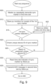
- FIG. 9 and FIG. 10 are flow charts illustrating respective processing steps 805 - 875 carried out by the master and slave processing units of the first and second hearing devices in connection with the above-outlined acquisition sequence according to embodiments of the exemplary binaural hearing system 125.
Landscapes
- Engineering & Computer Science (AREA)
- Computer Networks & Wireless Communication (AREA)
- Signal Processing (AREA)
- Multimedia (AREA)
- Health & Medical Sciences (AREA)
- General Health & Medical Sciences (AREA)
- Neurosurgery (AREA)
- Otolaryngology (AREA)
- Physics & Mathematics (AREA)
- Acoustics & Sound (AREA)
- Headphones And Earphones (AREA)
- Mobile Radio Communication Systems (AREA)
Abstract
The present disclosure relates to acquisition sequences of binaural hearing systems and corresponding binaural hearing systems. The binaural hearing systems may comprise first and second hearing devices, for example head-wearable devices at a user's ears, and first and second hearing implants.
Description
- The present disclosure relates to acquisition sequences of binaural hearing systems and corresponding binaural hearing systems. The binaural hearing systems may comprise first and second hearing devices, for example head-wearable devices at a user's ears, and first and second hearing implants.
- Binaural hearing systems that comprise a pair of hearing implants, such as cochlea hearing implants, may comprise at least four separate devices that are wirelessly connected via at least three bidirectional wireless communication links during normal operation. A first bidirectional wireless communication link must be connected between a first hearing device, typically arranged at, in or on a user's ear, and a first hearing implant such as a cochlea implant. A second bidirectional wireless communication link must be connected between a second hearing device, typically arranged at, in or on the user's opposite ear, and a second hearing implant. Finally, a third bidirectional wireless communication link must be connected between the first and second hearing devices, i.e. a bilateral link, to allow the devices at opposite sides of the user's head to communicate data for example digital audio signals to enable sophisticated binaural processing algorithms and/or synchronize other functions of the first and second hearing devices.
- There is need for a hearing systems, that for example use a common communication protocol between devices and implants, and support rapid and energy efficient acquisition of each of the first and second bidirectional wireless communication links as well as the bilateral link at start-up of the binaural hearing system. There is also a need for energy efficient operation of the first and second hearing devices and the first and second hearing implants during normal operation of the binaural hearing system. Each of the first and second hearing devices and the first and second hearing implants is typically a relatively small device energized by power sources with limited capacity like rechargeable batteries.
- A first aspect of the invention relates to a binaural hearing system comprising:
- a first hearing device, a second hearing device, a first hearing implant and a second hearing implant; wherein
- the first hearing device is connectable to the first hearing implant via a first bidirectional wireless communication link for exchange of first ipsilateral data packets,
- the second hearing device is connectable to the second hearing implant via a second bidirectional wireless communication link for exchange of second ipsilateral data packets,
- a bilateral bidirectional wireless communication link is connectable between the first hearing device and second hearing device for exchange of bilateral data packets. The bilateral bidirectional wireless communication link and said first and second bidirectional wireless communication links are preferably configured to operate in accordance with a common communication protocol. The common communication protocol comprises a plurality of consecutive frames each comprising a plurality of time slots and an acquisition sequence. The latter comprises:
- acquire the bilateral bidirectional wireless communication link using at least a first processing unit of the first hearing device and a second processing unit of the second hearing device,
- acquire the first bidirectional wireless communication link in response to acquisition of the bilateral bidirectional wireless communication link using at least the first processing unit of the first hearing device,
- acquire the second bidirectional wireless communication link in response to acquisition of the bilateral bidirectional wireless communication link using at least the second processing unit of the second hearing device.
- After a successful acquisition sequence of the binaural hearing system the latter preferably enters a normal operation mode where the first hearing device and the first hearing implant are wirelessly connected through the first bidirectional wireless communication link. The second hearing device and the second hearing implant are likewise wirelessly connected through the second bidirectional wireless communication link during normal operation. Finally, the first hearing device and the second hearing device are wirelessly connected through the bilateral bidirectional wireless communication link during normal operation. The common communication protocol may be proprietary and designed for minimal power consumption since each of the first and second hearing devices and each of the first and second hearing implants typically are relatively small battery powered devices or otherwise energized by a power source with limited capacity.
- One of the first hearing device and second hearing device is preferably configured as master and the other one as slave for the purpose of acquiring and operating the bilateral bidirectional wireless communication link using their respective first and second processing units as discussed in additional detail below with reference to the appended drawings.
- Each of the first and second hearing devices may comprise a head-wearable housing shaped and sized similarly to a traditional hearing aid for example of so-called BTE, ITE, ITC, CIC or RIC types of housings. The housings may be shaped and sized for placement at, or in, a user's left or right ear for example shaped and sized for placement behind the user's left and right ear pinna. The first and second hearing implants may be configured for placement at respective sides of the user's skull and configured to supply respective nerve stimulus signals to the user's left and right hearing nerves via implanted electrode arrays.
- Each of the first and second bidirectional wireless communication links and the bilateral bidirectional wireless communication link may be based on near-field magnetic coupling, such as NFMI, using respective magnetic coil antennas mounted in the first and second hearing devices. Each of the first and second bidirectional wireless communication links and the bilateral bidirectional wireless communication link may for example use a carrier frequency between 5 and 50 MHz as discussed in additional detail below with reference to the appended drawings.
- According to one embodiment of the binaural hearing system at least a subset of the first and second ipsilateral data packets comprises respective digital audio data such as real-time digital audio signals; and/or at least a subset of the bilateral data packets comprises respective digital audio data such as real-time digital audio signals as discussed in additional detail below with reference to the appended drawings.
- Each of the first processing unit and second processing unit may comprise a digital signal processor (DSP) and/or a microprocessor such as a software programmable DSP or a software programmable microprocessor. The software programmable DSP or microprocessor may be configured to execute plurality of program instructions configured to implement at least parts of the respective acquisitions of the first and second bidirectional wireless communication links and the bilateral bidirectional wireless communication link in accordance with the common communication protocol. Each of the first processing unit and second processing unit may comprise a dedicated digital state machine configured to handle certain steps of the acquisitions of the first and second bidirectional wireless communication links and the bilateral bidirectional wireless communication link in accordance with the common communication protocol.
- According to an embodiment of the common communication protocol and corresponding binaural hearing system the acquisition of the bilateral bidirectional wireless communication link comprises:
- transmit a first synchronization marker from the first processing unit to the second processing unit in a first time slot at the first processing unit,
- monitor the plurality of time slots at the second processing unit for the first synchronization marker,
- slide the plurality of time slots at the second processing unit with predetermined time steps from frame to frame of the plurality of consecutive frames using a wrap-around scheme,
- detect the first synchronization marker at the second processing unit,
- transmit an acknowledge message from the second processing unit to the first processing unit in a second time slot at the first processing unit,
- synchronize the plurality of time slots at the second processing unit with the plurality of time slots at the first processing unit based on the first synchronization marker,
- complete the acquisition of the bilateral bidirectional wireless communication link,
- start the exchange of the bilateral data packets through the bilateral bidirectional wireless communication link in the first and second times slots of the consecutive frames.
- A "time slot" is the shortest time division of the bilateral bidirectional wireless communication link and first and second bidirectional wireless communication links as defined by the common communication protocol. One data packet may for example be transmitted in one time slot.
- A "frame" is a unit of data that comprises a predefined number of time slots as defined by a communication protocol.
- "Connectable" shall mean that the wireless communication link in question is configured to establish a wireless connection between specified devices after acquisition of the wireless communication link in question.
- A "bidirectional wireless communication link" is a wireless communication link that supports transmission of data packets or data messages from a first device to a second device and transmission of data packets or data messages from the second device to the first device.
- "Ipsilateral data packets" are data packets exchanged between a hearing device and a hearing implant arranged at the same side of a user's head.
- A "hearing implant" shall mean that portion of a cochlear implant that is located inside the user's skull.
- According to an embodiment of the common communication protocol and corresponding binaural hearing system the acquisition of the first bidirectional wireless communication link comprises:
- transmit a second synchronization marker from the first processing unit to a first implant processor of the first hearing implant in a third time slot at the first processing unit,
- monitor the plurality of time slots at the first implant processor for receipt of the second synchronization marker,
- sliding the plurality of time slots at the first implant processor with predetermined time steps from frame to frame of the consecutive frames using a wrap-around scheme,
- detect the second synchronization marker at the first implant processor,
- synchronize the plurality of time slots at first implant processor with the plurality of time slots at the first processing unit based on the second synchronization marker,
- complete the acquisition of the first bidirectional wireless communication link,-transmit an acknowledge message from the first implant processor to the first processing unit in a fourth time slot at the first processing unit; and
- transmit a third synchronization marker from the second processing unit to a second implant processor of the second hearing implant in a third time slot at the second processing unit,
- monitor the plurality of time slots, at the second implant processor for receipt of the third synchronization marker,
- sliding the plurality of time slots at the second implant processor with predetermined time steps from frame to frame of the plurality of consecutive frames using a wrap-around scheme,
- detect the third synchronization marker at the second implant processor,
- synchronize the plurality of time slots at second implant processor with the plurality of time slots at the second processing unit based on the third synchronization marker,-transmit an acknowledge message from the second implant processor to the second processing unit in a fourth time slot at the second processing unit,
- complete the acquisition of the second bidirectional wireless communication link; and complete the acquisition sequence and enter normal operation of the binaural hearing system.
- Each frame of the plurality of consecutive time frames may comprise at least four time slots such as four overlapping time slots. The length of each of the at least four time slots may be identical as discussed in additional detail below with reference to the appended drawings.
- In one embodiment each of the predetermined time steps for the sliding of the plurality of time slots is less than 5 %, for example less than 1 %, of a length of one time slot of the plurality of time slots of the frame as discussed in additional detail below with reference to the appended drawings.
- According to an embodiment of the common communication protocol and corresponding binaural hearing system, the first synchronization marker comprises a unique pair ID for pairing the first hearing device and the second hearing device; and
- the second synchronization marker comprises a unique pair ID for pairing the first hearing device and first hearing implant; and
- the third synchronization marker comprises a unique pair ID for pairing the second hearing device and the second hearing implant.
- The first synchronization marker transmitted from the first processing unit to the second processing unit during acquisition of the bilateral bidirectional wireless communication link may for example comprise a first unique pair ID. The second processing unit is configured to:
- compare the first unique pair ID of the synchronization marker with a pre-stored unique pair ID,
- ignore the first synchronization marker if the first unique pair ID does not match the pre-stored unique pair ID; and
- transmit the acknowledge message if the pre-stored unique pair ID matches the first unique pair ID of the first synchronization marker. Certain embodiments of the binaural hearing system utilize three unique pair IDs, i.e. two additional unique pair IDs in addition to the first unique pair ID, in the above-mentioned pairings of the first hearing device and the first hearing implant, the first hearing device and the second hearing device and the second hearing device and the second hearing implant. This embodiment is favourable because the use of unique pair IDs of the first, second and third synchronization markers avoids erroneous pairings of devices of the binaural hearing system during the acquisition sequence as discussed in further detail below with reference of the appended drawings.
- The synchronization marker may at least comprise:
- a predetermined binary pattern,
- a time slot indicator for indicating which time slot of the plurality of time slots at the first processing unit that holds the synchronization marker, and optionally and error-detecting code.
- The common communication protocol may comprise a plurality of super frames each comprising a plurality of individual frames, such as between 4 and 32 individual frames, of the plurality of consecutive frames. In the latter embodiment, the second processing unit is preferably configured to determine an offset in frames between consecutive super frames,
- transmit the offset to the first processing unit via the bilateral bidirectional wireless communication link while the first processing unit is configured to read the offset and adjust timing of the super frames at the first processing unit to align super frames at the first and second processing units.
- According to one embodiment of the binaural hearing system, the acquisition sequence comprises:
- maintain connection through the bilateral bidirectional wireless communication link during the acquisition of the first bidirectional wireless communication link and during the acquisition of the second bidirectional wireless communication link.
- A second aspect of the invention relates to an acquisition sequence, e.g. an computer-implemented acquisition method, in accordance with the common communication protocol for acquiring respective connections between a first hearing device and a first hearing implant, a second hearing device and a second hearing implant and the first hearing device and the second hearing device. The acquisition sequence comprising:
- acquire a bilateral bidirectional wireless communication link between the first hearing device and the second hearing device using at least a first processing unit of the first hearing device and a second processing unit of the second hearing device,
- exchange bilateral data packets between the first hearing device and the second hearing device,
- acquire a first bidirectional wireless communication link between the first hearing device and the first hearing implant, in response to acquisition of the bilateral bidirectional wireless communication link, using at least the first processing unit of the first hearing device,
- exchange first ipsilateral data packets between the first hearing device and the first hearing implant,
- acquire a second bidirectional wireless communication link between the second hearing device and second hearing implant, in response to acquisition of the bilateral bidirectional wireless communication link, using at least the second processing unit of the second hearing device
- exchange second ipsilateral data packets between the second hearing device and the second hearing implant;
- enter normal operation of the binaural hearing system.
- One embodiment of the acquisition sequence comprises:
- exchange the bilateral data packets in first and second time slots at the first processing unit of respective frames of the plurality of consecutive frames,
- exchange the first ipsilateral data packets in third and fourth time slots at the first processing unit of the respective frames of the plurality of consecutive frames,
- exchange the second ipsilateral data packets using in the third and fourth time slots at the second processing unit of respective frames of the plurality of consecutive frames.
- In the following exemplary embodiments of the invention are described in more detail with reference to the appended drawings, wherein:
-
FIG. 1 schematically illustrates an exemplary binaural hearing system in accordance with the invention mounted on user's head, -
FIG. 2 shows respective schematic block diagrams of first and second hearing devices and associated first and second hearing implants of the exemplary binaural hearing system, -
FIG. 3 schematically illustrates transmission of a first synchronization marker from the first hearing device to the second hearing device during acquisition of a bilateral bidirectional wireless communication link according to embodiments of the exemplary binaural hearing system, -
FIG. 4 schematically illustrates exchange of bilateral data packets between the first hearing device and the second hearing device after the acquisition of the bilateral bidirectional wireless communication link according to embodiments of the exemplary binaural hearing system, -
FIG. 5 schematically illustrates acquisition of the first bidirectional wireless communication link and acquisition of the second bidirectional wireless communication link in accordance with embodiments of the exemplary binaural hearing system, -
FIG. 6 schematically illustrates exchange of first and second ipsilateral data packets and exchange of bilateral data packets during normal operation, i.e. payload mode, of the binaural hearing system after completion of an acquisition sequence in accordance with embodiments of the exemplary binaural hearing system, -
FIG. 7 illustrates features of an exemplary synchronization marker utilized during the acquisition of the bilateral bidirectional wireless communication link in accordance with the embodiments of the exemplary binaural hearing system, -
FIG. 8 illustrates exemplary super-frame structures each comprising a plurality of frames of the ipsilateral data packets and bilateral data packets in accordance with the embodiments of the exemplary binaural hearing system, -
FIG. 9 andFIG. 10 are flow charts illustrating respective processing steps carried out by the first and second processing units of the first and second hearing devices, respectively, during acquisition of the bilateral bidirectional wireless communication link according to embodiments of the exemplary binaural hearing system. - In the following various exemplary embodiments of the present hearing system are described with reference to the appended drawings. The skilled person will understand that the accompanying drawings are schematic and therefore merely show details which are essential to understanding of the invention. Other details may have been left out or simplified for brevity and clarity. Like reference numerals refer to like elements throughout the drawings. Like elements will, thus, not necessarily be described in detail with respect to each drawing.
-
FIG. 1 schematically illustrates afirst hearing device 100L and afirst hearing implant 150L of an exemplarybinaural hearing system 125. Thebinaural hearing system 125 further comprises asecond hearing device 100L and asecond hearing implant 150L both arranged at the opposite side of the user'shead 250 and therefore not visible. Thefirst hearing implant 150L is adapted for surgical implantation in the user's skull and therefore invisible from the outside when implanted. Thesecond hearing implant 150R is arranged in a corresponding manner at the opposite side of the user'shead 250. -
FIG. 2 is a block diagram of thebinaural hearing system 125. Thefirst hearing device 100L is connectable to thefirst hearing implant 150L via a first bidirectionalwireless communication link 112L ("first link") for exchange of first ipsilateral data packets. Thesecond hearing device 100L is likewise connectable to thesecond hearing implant 150L via a second bidirectionalwireless communication link 112L ("second link") for exchange of second ipsilateral data packets. - The
binaural hearing system 125 further comprises a bilateral bidirectional wireless communication link 114 ("bilateral link", or "third link") that is connectable between thefirst hearing device 100L andsecond hearing device 100R for exchange of bilateral data packets. Thefirst hearing device 100L andsecond hearing device 100R are preferably configured to use the respectivemagnetic coil antennas first hearing implant 150L andsecond hearing implant 150R, respectively. Thebilateral link 114,first link 112L andsecond link 112R are preferably configured to utilize, i.e. operate in accordance with, a common data communication protocol. The common data communication protocol comprises a plurality of consecutive time frames that each comprises a plurality of time slots holding the first and second ipsilateral data packets and the bilateral data packets. The respective pluralities of first and second ipsilateral data packets and bilateral data packets are structured, transmitted and received in accordance with the common data communication protocol as discussed in further detail below. - The skilled person will understand that certain types of data packets such as synchronization markers and acknowledge messages may be wirelessly transmitted between the
first hearing device 100L andsecond hearing device 100R, between thefirst hearing device 100L and thefirst hearing implant 150L and between thesecond hearing device 100Rsecond hearing implant 150R before the respective acquisitions of thebilateral link 114,first link 112L andsecond link 112R. - The bilateral data packets exchanged by the
bilateral link 114 may comprise digital audio samples and control information transmitted by respective ones of the first andsecond hearing devices second hearing devices second hearing implant second hearing implants second hearing devices first link 112L andsecond link 112R. In the latter embodiment both of thefirst link 112L andsecond link 112R are adapted for bidirectional data transfer. - Each of the
first link 112L,second link 112R andbilateral link 114 may in certain embodiments of the invention be based on, or comprise, near-field magnetic coupling, such as NFMI links. Thefirst link 112L may accordingly comprise amagnetic coil antenna 116R of thefirst hearing device 100L and amagnetic coil antenna 102R of thefirst hearing implant 150L. Thesecond link 112R may likewise comprise amagnetic coil antenna 116L of thesecond hearing device 100L and amagnetic coil antenna 102L of thesecond hearing implant 100L. Each offirst link 112L,second link 112R andbilateral link 114 may for example utilize a carrier frequency between 5 MHz and 50 MHz, such as between 9 MHz and 27 MHz for transmissions of the first and second ipsilateral data packets and the bilateral data packets. - The
first hearing implant 150L comprises thefirst control unit 108L that is connected to themagnetic coil antenna 102L for receipt and processing of the first ipsilateral data packets transmitted by thefirst hearing device 100L. Thefirst control unit 108L is further configured to transmit the first ipsilateral data packets to thefirst hearing device 100L via thefirst link 112L. In some embodiments, afirst processing unit 108L of thefirst hearing implant 150L may comprise a digital signal processor (DSP) and/or a microprocessor. Certain embodiments of thefirst hearing implant 150L may comprise arechargeable battery assembly 104L. Therechargeable battery assembly 104L is configured for receiving electrical power from a receiver (Rx) chargingcoil 110L during dedicated recharging operations or sessions. The receiver (Rx) chargingcoil 110L may be energized by an appropriately positioned external, i.e. outside the user's skull, transmitter (Tx) charging coil (not shown) of a charging device (not shown) during the dedicated recharging sessions. This allows wireless transfer of power to therechargeable battery assembly 104L. Therechargeable battery assembly 104L is preferably coupled to a power supply input of animplant processor 108L to energize the latter as schematically indicated by a power line orwire 107L. Theimplant processor 108L may comprise a microprocessor for example software programmable microprocessor. - The
first hearing implant 150L further comprises anelectrode array 106L for insertion into a cochlea of the user during implantation. Theelectrode array 106L may be electrically coupled to thefirst processing unit 108L that supplies suitable electrode stimuli signals to theelectrode array 106L to stimulate the user's cochlea nerve. The skilled person will understand that these electrode stimuli signals may be generated by thefirst processing unit 108L and derived by the latter based on the first ipsilateral data packets, in particular digital audio signals or data embedded or held in the first ipsilateral data packets. The skilled person will appreciate that corresponding functions, structures and features of thesecond hearing implant 150R may be largely identical to those of thefirst hearing implant 150L. - The block diagram on
FIG. 2 further illustrates an exemplary embodiment of thefirst hearing device 100L. Thefirst hearing device 100L comprises themagnetic coil antenna 116L which is electrically connected to atransceiver 118L. Thetransceiver 118R is configured to repeatedly switch between Tx and Rx modes to modulate and demodulate incoming and outgoing data of the first ipsilateral data packets and bilateral data packets. Thetransceiver 118L may be configured to convert the first ipsilateral data packets and bilateral data packets to a format understood by afirst processing unit 120L of thefirst hearing device 100L. In some embodiments, thefirst processing unit 120L may comprise a digital signal processor (DSP) and/or a microprocessor such as a software programmable DSP or a microprocessor. - The
first hearing device 100L further comprises one ormore microphones 124L that are coupled to an appropriate audio interface of thefirst processing unit 120L. Thefirst processing unit 120L may be configured to execute a suitable operating system. The operating system may be configured to manage various hardware and software resources of thefirst hearing device 100L such as handling of the common communication protocol, computation of monaurally or bilaterally beamformed microphone signals, hearing loss compensation processing of the microphone signal(s), the first wirelessdata communication interface 118L, certain memory resources etc. The operating system may schedule tasks for efficient use of hearing device resources and may further include accounting software for cost allocation, including power consumption, processor time, memory locations, wireless transmissions, and other resources. The operating system may be stored in and retrieved from a non-volatile memory (not shown), e.g. flash memory or EEPROM, of theprocessing unit 120L. - Each of the first and
second hearing devices first hearing device 100L further comprises asystem clock generator 126L that is configured to supply system clock signals to various digital logic circuits and components of thedevice 100L including thefirst processing unit 120R as schematically illustrated. A nominal value of a clock frequency of thesystem clock generator 126R may lie between 2 MHz and 64 MHz such as between 10 MHz and 50 MHz. Thefirst processing unit 120R may be configured to derive respective lengths of certain time slots and time frames of the common communication protocol of thefirst link 112L and thebilateral link 114 as discussed in additional detail below. - The
first hearing device 100L may additionally comprises a second, optional,wireless communication interface 128L andRF antennal 130L configured to jointly communicate through a second wireless communication link (not shown). The second wireless communication link and interface may be configured to operate in the 2.4 GHz industrial scientific medical (ISM) band and may be compliant with a Bluetooth LE standard. This second wireless communication link may provide convenient data connectivity to various types of portable communication devices like smartphones, mobile phones, tablets and personal computers etc. due to the industry standard compatible nature of the second wireless communication link. Various types of control data and audio data may be transmitted from the portable communication device to thefirst hearing device 100L and vice versa. Thesecond hearing device 100L may for the same purpose comprise a similar optional secondwireless communication interface 128L andRF antenna 130L as illustrated. - In the following disclosure the
first hearing device 100L of thebinaural hearing system 125 is assigned as master during execution of the common communication protocol while thesecond hearing device 100R is configured as a slave. The skilled person will understand that the system clock signal of themaster processing unit 120L may control timing of transmissions of respective data packets through thefirst link 112L,second link 112R andbilateral link 114 at least after the acquisitions of thefirst link 112L,second link 112R andbilateral link 114. -
FIG. 3 schematically illustrates transmission of afirst synchronization marker 465c from themaster processing unit 120L of the first ormaster hearing device 100L to the second orslave hearing device 100R during acquisition of thebilateral link 114 according to embodiments of the common communication protocol of the exemplarybinaural hearing system 125. During the acquisition of thebilateral link 114, themaster processing unit 120L operates as a master device towards thesecond hearing device 100R. Themaster processing unit 120L may start to repeatedly transmit thefirst synchronization marker 465c to thesecond hearing device 100R. using one of a plurality of time slots, e.g. time slots 1-4, of each frame, Frame-1, Frame-2 etc., of a plurality of consecutive frames. The indicated time slots 1-4 are referenced to themaster processing unit 120L.Time slot 1, at themaster processing unit 120L, is selected for transmission of thefirst synchronization marker 465c in the present example as illustrated and made in accordance with the common communication protocol. Thesecond hearing device 100R resides concurrently in a receipt mode such that the second, or slave, processingunit 102R of theslave hearing device 100R monitors thebilateral link 114 to detect receipt of thefirst synchronization marker 465c. However, the respective time slots 1-4 at themaster processing unit 120L and thefirst hearing implant 150L are most likely more or less unaligned or non-synchronous at the current acquisition step of the acquisition sequence caused by free-running clock generators and system clock signals at themaster processing unit 120L and theslave processing unit 120R. As illustrated byFIG. 3 where theslave hearing device 100R searches for thefirst synchronization marker 465c in atime slot 471 at theslave hearing device 100R whichexemplary time slot 471 is shifted or misaligned, as indicated by the S-slot-2 arrow, with about one-fourth of the length of one time slot relative to the time slots at themaster processing unit 120L. This misalignment of time slots prevents theslave hearing device 100R from detecting thefirst synchronization marker 465c because the latter extends across two adjacent time slots at theslave hearing device 100R. Theslave processing unit 120R advances or slides its time slots 1-4, such as theexemplary time slot 471, with predetermined time steps between frames of the plurality of consecutive frames using a wrap-around scheme as schematically indicated by "Time slide" arrow. The wrap-around scheme means that that the sliding of the time slotsslave processing unit 120R, such as S-slot 2, jumps back totime slot 1 when the end oftime slot 4 is reached by the sliding operation. The predetermined time step for the slot sliding is preferably much shorter than a length of one time slot such as less 5 % or less than 1 % of the length of one time slot to gradually align the time slots 1-4 at theslave processing unit 120R with the time slots 1-4 at themaster processing unit 120L. Theslave processing unit 120R may continue to slide its time slots 1-4 by a wrap-around scheme until the latter time slots are sufficiently aligned with the time slots 1-4 at themaster processing unit 120L to detect receipt of thefirst synchronization marker 465c at theslave processing unit 120R. Theslave processing unit 120R may check the unique pair ID of the received first synchronization marker to ensure it is transmitted from the paired device, i.e. themaster hearing device 100L in the present situation. The search for thefirst synchronization marker 465c by theslave processing unit 120R may optionally comprise recognition of a predetermined search sequence 701 (FIG. 7 ) as described in further detail below. - The
slave processing unit 120R may be configured to ignore thefirst synchronization marker 465c if it is not transmitted by the paired device, i.e. the unique pair ID of the received synchronization marker does not match that of thefirst synchronization marker 465c. In the latter situationslave processing unit 120R may thereafter continue the search for thefirst synchronization marker 465a. When the unique pair ID of the received synchronization marker is a match to that of thefirst synchronization marker 465c, theslave processing unit 120R may respond by detecting the time slot,e.g. time slot 1, at themaster processing unit 120L in which thefirst synchronization marker 465c was transmitted by a slot indicator bit or field of the first synchronization marker as discussed in further detail below. Theslave processing unit 120R may, based on that time slot identification, align, i.e. synchronize, the time slots at theslave processing unit 120R with the corresponding time slots at themaster processing unit 120L of thefirst hearing device 100L. Hence, synchronize data packet exchange or communication between theslave processing unit 120R and themaster processing unit 120L through thebilateral link 114. - The
slave processing unit 120R thereafter shifts to a transmission mode and transmits an acknowledge message 470 (ACK) to themaster processing unit 120L intime slot 2 at themaster processing unit 120L as schematically illustrated byFIG. 3 . Thereafter, themaster processing unit 120L may respond by completing or terminating the acquisition of thebilateral link 114 because the latter is now appropriately connected between the master processing unit 120 and theslave processing unit 120R in accordance with exemplary embodiments of the common communication protocol of thebinaural hearing system 125. Themaster processing unit 120L and theslave processing unit 120R are accordingly ready to exchange thebilateral data packets time slots FIG. 4 . Intime slot 1 offrame 1, themaster processing unit 120L transmits a firstbilateral data packet 430 to theslave processing unit 120R which resides in a receipt mode or state duringtime slot 1. Intime slot 2 offrame 1, theslave processing unit 120R transmits a secondbilateral data packet 480 to themaster processing unit 120L which now has switched to a receipt mode or state duringtime slot 2. - The skilled person will understand that other embodiments of the common communication protocol may specify more than four time slots per frame such as between 5 and 16 time slots. Irrespective of the actual number of time slots, such as at least four time slots, these are preferably non-overlapping time slots. Each time slot may have a length between 24 µs and 384 µs for example depending a number of bits of at least some of the exchanged data packets. The length of each of the time slots may be identical. Each of the first
ipsilateral data packets ipsilateral data packets - At least some of the
bilateral data packets bilateral data packets slave hearing devices slave hearing devices bilateral data packets slave hearing devices -
FIG. 5 schematically illustrates acquisition of thefirst link 112L and acquisition of thesecond link 112R in accordance with embodiments of the exemplarybinaural hearing system 125. As outlined above the acquisition of thebilateral link 114 has been completed and in response themaster processing unit 120L initiates the acquisition of thefirst link 112L and the acquisition of thesecond link 112R.FIG. 5 illustrates how themaster processing unit 120L and theslave processing unit 120R exchange thebilateral data packets time slots master processing unit 120L may further be configured to repeatedly generate and transmit thesecond synchronization marker 465a to thefirst control unit 108L of thefirst hearing implant 150L using an unoccupied time slot of the frames, liketime slot 3, at themaster processing unit 120L. Thefirst control unit 108L operates in its receipt mode and searches for thesecond synchronization marker 465a in atime slot 571 at theslave hearing device 100R. Theexemplary time slot 571 is shifted or misaligned, as indicated by the S-slot-2 arrow, with about one-fourth of the length of one time slot relative to the time slots at themaster processing unit 120L indicated on the x-axis. This misalignment of time slots prevents thefirst control unit 108L from detecting thesecond synchronization marker 465a for the reasons discussed above in connection with thefirst synchronization marker 465c. Thefirst control unit 108L therefore advances or slides its time slots 1-4, such as theexemplary time slot 571, with predetermined time steps from frame to frame of the plurality of consecutive frames using a wrap-around scheme as schematically indicated by "Time slide"arrow 575. The predetermined time step is preferably shorter than the length of one time slot such as less 5 % or less than 1 % of the length of one time slot. The predetermined time step may be 250 ns for a slot length of about 48 µs. Following this scheme, thefirst control unit 108L is configured to gradually align the time slots 1-4 at thefirst control unit 108L with the time slots 1-4 at themaster processing unit 120L. Thefirst control unit 108L may continue to slide its time slots 1-4 until the latter time slots are sufficiently aligned with the time slots 1-4 at themaster processing unit 120L to detect receipt of thesecond synchronization marker 465a at thefirst control unit 108L. The first control unit 108 may optionally proceed to check the unique pair ID of the receivedsynchronization marker 465a to ensure it is transmitted from a paired device, i.e. themaster hearing device 100L in the present situation. Thefirst control unit 108L may be configured to ignore the synchronization marker if it is not transmitted by the paired device, i.e. the unique pair ID of the received synchronization marker does not match that of thesecond synchronization marker 465a. In the latter situation, thefirst control unit 108L may thereafter continue searching for thesecond synchronization marker 465a. When the unique pair ID of the receivedsynchronization marker 465a is a match, thefirst control unit 108L may respond by reading theslot indicator 709 of thethird synchronization marker 465b and align its time slots 1-4 at with the corresponding time slots at themaster processing unit 120L to synchronize the ipsilateral data packet exchange between thefirst hearing implant 150L and themaster hearing device 100L through thefirst link 112L. Thefirst control unit 108L thereafter shifts to a transmission mode and transmit an acknowledge message (not shown) to themaster processing unit 120L in theunoccupied time slot 4 at themaster processing unit 120L. - The
master processing unit 120L may respond to receipt of the acknowledge message by completing the acquisition of thefirst link 112L because the latter is now appropriately connected between themaster hearing device 100L and thefirst hearing implant 150L in accordance with the exemplary embodiments of the common communication protocol of thebinaural hearing system 125. Themaster hearing device 100L and thefirst implant 150L are accordingly ready to exchange the firstipsilateral data packets time slots FIG. 6 . Intime slot 3 offrames 1, themaster hearing device 100L transmits, TxM, an ipsilateralbilateral data packet 455 to thefirst hearing implant 150L. - The
first implant 150L resides in the receipt mode or state intime slot 3. Intime slot 4 offrames 1, thefirst hearing implant 150L transmits, Txl1,, a secondipsilateral data packet 460 to themaster processing unit 120L which now has switched to a receipt mode or state, from the previous transmit mode intime slot 3. Further intime slot 4 of the frames, thesecond hearing implant 150R transmits, Txl2, a secondipsilateral data packet 410 to theslave processing unit 120R which now has switched to a transmission mode or state from the previous receipt mode intime slot 3. The skilled person will appreciate that the acquisition of thesecond link 112R of the exemplarybinaural hearing system 125 may follow a corresponding acquisition scheme of thefirst link 112R to create the wireless connection between theslave hearing device 100R and thesecond hearing implant 150R. Preferably, theslave processing unit 120R operates as a master device towards thesecond hearing implant 150R during acquisition. Briefly, theslave processing unit 120L may be configured to repeatedly generate and transmit thethird synchronization marker 465b to thesecond control unit 108L of thesecond hearing implant 150R using an unoccupied time slot of the frames, liketime slot 3, at themaster processing unit 120L. The third synchronization marker has a different pair ID, than that of each of the first andsecond synchronization markers slave processing unit 120R and thesecond hearing implant 150L for the acquisition of thesecond link 112R. Thesecond control unit 108L advances or slides its time slots 1-4, such as theexemplary time slot 573, with predetermined time steps in the same manner as described in detail above in connection with the acquisition of thesecond link 112R. After completions of the acquisitions of the first andsecond links master processing unit 120L responds by completing, e.g. terminating, the acquisition sequence of the exemplarybinaural hearing system 125. Themaster processing unit 120L, theslave processing unit 120R, thefirst hearing implant 150L andsecond hearing implant 120R enter normal operation, i.e. a "payload mode", where the first and secondipsilateral data packets time slots bilateral data packets time slots FIG. 6 . - Some embodiments of the common communication protocol comprise that the
master processing unit 120L is configured to respond to receipt of each of the acknowledge messages by starting a count-down sequence before each link acquisition is completed. The count-down sequence may comprises an exchange of several rounds, e.g. 2, 3 or 4 rounds, of the synchronization marker in question and the accompanying acknowledge message before termination of the link acquisition. The optional use of count-down sequences may further verify the reliability of the link in question. - The above outlined time-slot based scheme for synchronous transmission of the first and second ipsilateral data packets and
bilateral data packets binaural hearing system 125, as devised by the common communication protocol, leads to efficient use of the bandwidth of the respective wireless links. This time-slot based scheme for synchronous transmission is additionally energy efficient for the respective transceiver circuitries of themaster processing unit 120L, theslave processing unit 120R, thefirst hearing implant 150L andsecond hearing implant 120R. -
FIG. 7 illustrates anexemplary synchronization marker 465 that may be utilized for the respective acquisitions of the bilateral bidirectionalwireless communication link 114, thefirst link 112L and thesecond link 112R. Theexemplary synchronization marker 465 preferably comprisesunique pair IDs 703 such as a unique number or code. Aunique pair ID 703 may comprise between 8 bits and 32 bits. A firstunique pair ID 703 may be utilized to pair themaster hearing device 100L and thefirst hearing implant 150L to each other. The firstunique pair ID 703 may be stored in a memory of themaster processing unit 120L and further stored in a memory of thefirst control unit 108L of thefirst hearing implant 150L. The firstunique pair ID 703 may for example be stored during manufacture of themaster hearing device 100L or later in connection with a fitting of thebinaural hearing system 125 to the user. The firstunique pair ID 703 may be stored in a similar manner in the memory of thefirst control unit 108L. A secondunique pair ID 703 may be utilized to pair theslave hearing device 100L and thesecond hearing implant 150L to each other. The secondunique pair ID 703 may be stored in the memory of themaster processing unit 120L and further stored in a memory of thesecond control unit 108R of thesecond hearing implant 150R. The secondunique pair ID 703 may for example be stored in themaster processing unit 120L and thesecond control unit 108R in a similar manner to the firstunique pair ID 703 as outlined above. - A third
unique pair ID 703 may be utilized to pair theslave hearing device 100L and themaster hearing device 100L to each other. The thirdunique pair ID 703 may be stored in the memory of themaster processing unit 120L and further stored in the memory of theslave processing unit 120R. The thirdunique pair ID 703 may for example be stored in theslave processing unit 120R and themaster processing unit 120L in a similar manner to the firstunique pair ID 703 as outlined above. - The use of
unique pair IDs 703 ensures that only the appropriate pair of devices are connected to each other during the respective acquisitions of thefirst link 112L,second link 112R andbilateral link 114. Otherwise, unintended crosstalk between the devices, for example between the first and secondsecond hearing implants binaural hearing system 125 could lead to erroneous pairing of devices. Theunique pair IDs 703 in a similar manner prevents unintended crosstalk and erroneous pairing of devices of two different but nearby located bilateral hearing systems. - The
synchronization marker 465 can be viewed as special type of data packet and may have the same length and number of bits as at least some of the bilateral data packets. Thesynchronization marker 465 may comprise apredetermined search sequence 701 for example a predetermined binary pattern like 10101010 or equivalently 01010101. The latter is a priori known to both the master processing unit 120, theslave processing unit 120R and each of the first andsecond control units slave processing unit 120R to detect thefirst synchronization marker 465c in a currently unoccupied time slot at theslave processing unit 120R. The predetermined binary pattern may likewise be received and recognized by thefirst control unit 108L of thefirst hearing implant 150L to detect thesecond synchronization marker 465a in a currently unoccupied time slot at thefirst control unit 108L. The predetermined binary pattern may likewise be received and recognized by thesecond control unit 108R of thesecond hearing implant 150R in a similar manner. - The
synchronization marker 465 may comprise an optional wrap-around count-down number. The latter may be utilized by themaster processing unit 120L andslave processing unit 120R for providing an additional layer of safety once theslave processing unit 120R andmaster processing unit 120L have acknowledged each other through the bilateral link as described in additional detail below. Aslot indicator 709 tells theslave processing unit 120R in which time slot at the master side thesynchronization marker 465 is arranged. This feature allows theslave processing unit 120R aligning its time slots with the corresponding time slots at themaster processing unit 120L. Theslave processing unit 120R may for example determine a time offset between already known time slots at theslave processing unit 120R and the corresponding time slots at themaster processing unit 120R for alignment. Since, the length of a time slot, e.g. 48 µs, is known to theslave processing unit 120R at least via the common communication protocol the time offset can indicate slot alignment. -
FIG. 8 illustrates an exemplary super-frame structure comprising where each super-frame comprises a plurality of individual frames, such as between 4 and 32 individual frames, of the plurality of consecutive frames in accordance with one embodiment of the common communication protocol. The frames at the master side of the binaural hearing system are structured inconsecutive super-frames 901 and the super-frames at the slave side of the binaural hearing system are structured inconsecutive super-frames 951. Each frame such as frame-1 may carry the same type of data for example digital audio signals which means that all data packets of the frame in question hold the same type of data e.g. digital audio signals, control information or error-correction codes like CRC and/or forward error-correction codes (FEC) etc. The super-frames at the master and slave sides may be misaligned in time, i.e. a time off-set, as schematically illustrated by an off-setarrow 953. Theslave processing unit 120R may be configured to detect this time off-set and transmit that to themaster processing unit 120L which proceeds to align thesuper-frames -
FIG. 9 andFIG. 10 are flow charts illustrating respective processing steps 805 - 875 carried out by the master and slave processing units of the first and second hearing devices in connection with the above-outlined acquisition sequence according to embodiments of the exemplarybinaural hearing system 125.
Claims (16)
- A binaural hearing system comprising:a first hearing device, a second hearing device, a first hearing implant and a second hearing implant; whereinthe first hearing device is connectable to the first hearing implant via a first bidirectional wireless communication link for exchange of first ipsilateral data packets,the second hearing device is connectable to the second hearing implant via a second bidirectional wireless communication link for exchange of second ipsilateral data packets,a bilateral bidirectional wireless communication link is connectable between the first hearing device and second hearing device for exchange of bilateral data packets; whereinsaid bilateral bidirectional wireless communication link and said first and second bidirectional wireless communication links are configured to operate in accordance with a common communication protocol which comprises a plurality of consecutive frames each comprising a plurality of time slots;said common communication protocol comprising an acquisition sequence which comprises:acquire the bilateral bidirectional wireless communication link using at least a first processing unit of the first hearing device and a second processing unit of the second hearing device,acquire the first bidirectional wireless communication link in response to acquisition of the bilateral bidirectional wireless communication link using at least the first processing unit of the first hearing device,acquire the second bidirectional wireless communication link in response to acquisition of the bilateral bidirectional wireless communication link using at least the second processing unit of the second hearing device.
- A binaural hearing system according to claim 1, wherein the acquisition of the bilateral bidirectional wireless communication link comprises:- transmit a first synchronization marker from the first processing unit to the second processing unit in a first time slot at the first processing unit,- monitor the plurality of time slots at the second processing unit for the first synchronization marker,- slide the plurality of time slots at the second processing unit with predetermined time steps from frame to frame of the plurality of consecutive frames using a wrap-around scheme,- detect the first synchronization marker at the second processing unit,- synchronize the plurality of time slots at the second processing unit with the plurality of time slots at the first processing unit based on the first synchronization marker,- transmit an acknowledge message from the second processing unit to the first processing unit in a second time slot at the first processing unit,- complete the acquisition of the bilateral bidirectional wireless communication link,- start the exchange of the bilateral data packets through the bilateral bidirectional wireless communication link in the first and second times slots of the consecutive frames.
- A binaural hearing system according to claim 1 or 2, wherein:
the acquisition of the first bidirectional wireless communication link comprises:- transmit a second synchronization marker from the first processing unit to a first implant processor of the first hearing implant in a third time slot at the first processing unit,- monitor the plurality of time slots at the first implant processor for receipt of the second synchronization marker,- sliding the plurality of time slots at the first implant processor with predetermined time steps from frame to frame of the consecutive frames using a wrap-around scheme,- detect the second synchronization marker at the first implant processor,- synchronize the plurality of time slots at first implant processor with the plurality of time slots at the first processing unit based on the second synchronization marker,- transmit an acknowledge message from the first implant processor to the first processing unit in a fourth time slot at the first processing unit,- complete the acquisition of the first bidirectional wireless communication link. - A binaural hearing system according to claim 3, wherein: the acquisition of the second bidirectional wireless communication link comprises:- transmit a third synchronization marker from the second processing unit to a second implant processor of the second hearing implant in a third time slot at the second processing unit,- monitor the plurality of time slots, at the second implant processor for receipt of the third synchronization marker,- sliding the plurality of time slots at the second implant processor with predetermined time steps from frame to frame of the plurality of consecutive frames using a wrap-around scheme,- detect the third synchronization marker at the second implant processor,- synchronize the plurality of time slots at second implant processor with the plurality of time slots at the second processing unit based on the third synchronization marker,transmit an acknowledge message from the second implant processor to the second processing unit in a fourth time slot at the second processing unit,- complete the acquisition of the second bidirectional wireless communication link; andcomplete the acquisition sequence and enter normal operation of the binaural hearing system.
- A binaural hearing system according to any of claims 2-4, wherein- the first synchronization marker comprises a unique pair ID for pairing the first hearing device and the second hearing device; and- the second synchronization marker comprises a unique pair ID for pairing the first hearing device and first hearing implant; and- the third synchronization marker comprises a unique pair ID for pairing the second hearing device and the second hearing implant.
- A binaural hearing system according to claim 4, wherein the second processing unit is configured to:- compare the unique pair ID of the first synchronization marker with a pre-stored unique pair ID,- ignore the first synchronization marker if the unique pair ID does not match the pre-stored unique pair ID; and- transmit the acknowledge message if the pre-stored unique pair ID matches the unique pair ID of the first synchronization marker.
- A binaural hearing system according to any of claims 2-6, wherein said common communication protocol comprises:
a plurality of super frames each comprising a plurality of individual frames, such as between 4 and 32 individual frames, of the plurality of consecutive frames. - A binaural hearing system according to any of claims 3-7, wherein each of the predetermined time steps for the sliding of the plurality of time slots is less than 5 % of a length of one time slot of the plurality of time slots of the frame.
- A binaural hearing system according to any of claims 1-8, wherein the acquisition sequence comprises:- maintain connection through the bilateral bidirectional wireless communication link during the acquisition of the first bidirectional wireless communication link and/or during the acquisition of the second bidirectional wireless communication link.
- A binaural hearing system according to any of claims 4-9, wherein the second processing unit is configured to determine an offset in frames between consecutive super frames,- transmit the offset to the first processing unit via the bilateral bidirectional wireless communication link,- read the offset by the first processing unit,- adjust timing of the super frames at the first processing unit to align super frames at the first and second processing units.
- A binaural hearing system according to according to any of claims 2-10, wherein the synchronization marker at least comprises:- a predetermined binary pattern, and/or- a time slot indicator for indicating which time slot of the plurality of time slots at the first processing unit that holds the synchronization marker, and/or an error-detecting code.
- A binaural hearing system according to any of claims 2-11, wherein each frame of the plurality of consecutive time frames comprises at least four non-overlapping time slots.
- A binaural hearing system according to claim 12, wherein a length of each of the at least four non-overlapping time slots is identical.
- A binaural hearing system according to any of the preceding claims, wherein at least a subset of the first and second ipsilateral data packets comprises respective digital audio data such as real-time digital audio signals; and/or at least a subset of the bilateral data packets comprises respective digital audio data such as real-time digital audio signals.
- An acquisition sequence in accordance with a common communication protocol for acquiring respective connections between a first hearing device and a first hearing implant, a second hearing device and a second hearing implant and the first hearing device and the second hearing device;
said acquisition sequence comprising:- acquire a bilateral bidirectional wireless communication link between the first hearing device and the second hearing device using a first processing unit of the first hearing device and a second processing unit of the second hearing device,- exchange bilateral data packets between the first hearing device and the second hearing device,- acquire a first bidirectional wireless communication link between the first hearing device and the first hearing implant, in response to acquisition of the bilateral bidirectional wireless communication link, using the first processing unit of the first hearing device,- exchange first ipsilateral data packets between the first hearing device and the first hearing implant,- acquire a second bidirectional wireless communication link between the second hearing device and second hearing implant, in response to acquisition of the bilateral bidirectional wireless communication link, using the second processing unit of the second hearing device- exchange second ipsilateral data packets between the second hearing device and the second hearing implant;- enter normal operation of the binaural hearing system. - An acquisition sequence according to claim 15, comprising:- exchange the bilateral data packets in first and second time slots at the first processing unit of respective frames of the plurality of consecutive frames,- exchange the first ipsilateral data packets in third and fourth time slots at the first processing unit of the respective frames of the plurality of consecutive frames,- exchange the second ipsilateral data packets using in the third and fourth time slots at the second processing unit of respective frames of the plurality of consecutive frames.
Priority Applications (4)
| Application Number | Priority Date | Filing Date | Title |
|---|---|---|---|
| EP23165779.2A EP4440155A1 (en) | 2023-03-31 | 2023-03-31 | Acqusition sequences of binaural hearing systems comprising hearing implants |
| EP24713486.9A EP4690845A1 (en) | 2023-03-31 | 2024-03-26 | Acquisition sequences of binaural hearing systems comprising hearing implants |
| CN202480023231.6A CN120937393A (en) | 2023-03-31 | 2024-03-26 | Capture sequence for binaural hearing system comprising hearing implant |
| PCT/EP2024/058120 WO2024200444A1 (en) | 2023-03-31 | 2024-03-26 | Acquisition sequences of binaural hearing systems comprising hearing implants |
Applications Claiming Priority (1)
| Application Number | Priority Date | Filing Date | Title |
|---|---|---|---|
| EP23165779.2A EP4440155A1 (en) | 2023-03-31 | 2023-03-31 | Acqusition sequences of binaural hearing systems comprising hearing implants |
Publications (1)
| Publication Number | Publication Date |
|---|---|
| EP4440155A1 true EP4440155A1 (en) | 2024-10-02 |
Family
ID=85795415
Family Applications (2)
| Application Number | Title | Priority Date | Filing Date |
|---|---|---|---|
| EP23165779.2A Pending EP4440155A1 (en) | 2023-03-31 | 2023-03-31 | Acqusition sequences of binaural hearing systems comprising hearing implants |
| EP24713486.9A Pending EP4690845A1 (en) | 2023-03-31 | 2024-03-26 | Acquisition sequences of binaural hearing systems comprising hearing implants |
Family Applications After (1)
| Application Number | Title | Priority Date | Filing Date |
|---|---|---|---|
| EP24713486.9A Pending EP4690845A1 (en) | 2023-03-31 | 2024-03-26 | Acquisition sequences of binaural hearing systems comprising hearing implants |
Country Status (3)
| Country | Link |
|---|---|
| EP (2) | EP4440155A1 (en) |
| CN (1) | CN120937393A (en) |
| WO (1) | WO2024200444A1 (en) |
Citations (4)
| Publication number | Priority date | Publication date | Assignee | Title |
|---|---|---|---|---|
| US20090067653A1 (en) * | 2007-07-06 | 2009-03-12 | Cochlear Limited | Wireless communication between devices of a hearing prosthesis |
| US20120232616A1 (en) * | 2011-03-10 | 2012-09-13 | Erika Van Baelen | Wireless communications in medical devices |
| US20140214123A1 (en) * | 2013-01-28 | 2014-07-31 | Jan Janssen | Bilateral Communication in a Two-Channel System |
| EP3657818A1 (en) * | 2018-11-26 | 2020-05-27 | GN Hearing A/S | Near field magnetic induction wireless communication system with dynamic change of transmitting power |
-
2023
- 2023-03-31 EP EP23165779.2A patent/EP4440155A1/en active Pending
-
2024
- 2024-03-26 WO PCT/EP2024/058120 patent/WO2024200444A1/en not_active Ceased
- 2024-03-26 EP EP24713486.9A patent/EP4690845A1/en active Pending
- 2024-03-26 CN CN202480023231.6A patent/CN120937393A/en active Pending
Patent Citations (4)
| Publication number | Priority date | Publication date | Assignee | Title |
|---|---|---|---|---|
| US20090067653A1 (en) * | 2007-07-06 | 2009-03-12 | Cochlear Limited | Wireless communication between devices of a hearing prosthesis |
| US20120232616A1 (en) * | 2011-03-10 | 2012-09-13 | Erika Van Baelen | Wireless communications in medical devices |
| US20140214123A1 (en) * | 2013-01-28 | 2014-07-31 | Jan Janssen | Bilateral Communication in a Two-Channel System |
| EP3657818A1 (en) * | 2018-11-26 | 2020-05-27 | GN Hearing A/S | Near field magnetic induction wireless communication system with dynamic change of transmitting power |
Also Published As
| Publication number | Publication date |
|---|---|
| WO2024200444A1 (en) | 2024-10-03 |
| CN120937393A (en) | 2025-11-11 |
| EP4690845A1 (en) | 2026-02-11 |
Similar Documents
| Publication | Publication Date | Title |
|---|---|---|
| US8175306B2 (en) | Wireless communication between devices of a hearing prosthesis | |
| US11784678B2 (en) | Audio stream detection | |
| US10412567B1 (en) | Short-range wireless communication based on indirect transmission of communication parameters | |
| EP2633702B1 (en) | Pairing or associating electronic devices | |
| US8344689B2 (en) | Hearing aid and energy charger as well as associated method | |
| US7174214B2 (en) | General purpose accessory for a cochlear implant system | |
| EP2117180B1 (en) | A short range, uni-directional wireless link | |
| US9838829B2 (en) | Wireless streaming of an audio signal to multiple audio receiver devices | |
| EP2648800B1 (en) | Portable power charging of implantable medical devices | |
| JP6004588B2 (en) | Wireless communication in medical devices | |
| WO2010000027A1 (en) | Removable implantable battery positioned inside implant coil | |
| CN110381490A (en) | A kind of communication means, wireless headset and wireless device for wireless headset | |
| US9020169B2 (en) | Adaptive data rate for a bilateral hearing prosthesis system | |
| WO2015142355A1 (en) | Auditory prosthesis system including sound processor and wireless module for communication with an external computing device | |
| US20020191806A1 (en) | Hearing aid system with a programmable hearing aid and a transmission and/or reception unit, a transmission and/or reception unit as well as a programmable hearing aid | |
| US20260136142A1 (en) | Acquisition sequences of binaural hearing systems comprising hearing implants | |
| EP4440154B1 (en) | Recording sequences from binaural hearing systems with hearing implants | |
| EP4690845A1 (en) | Acquisition sequences of binaural hearing systems comprising hearing implants | |
| US20130223663A1 (en) | Wireless Streaming Link Break-in | |
| WO2013022444A1 (en) | Bilateral auditory prosthesis systems and methods | |
| KR102353157B1 (en) | Cochlear Implant System Using Body Area Network |
Legal Events
| Date | Code | Title | Description |
|---|---|---|---|
| PUAI | Public reference made under article 153(3) epc to a published international application that has entered the european phase |
Free format text: ORIGINAL CODE: 0009012 |
|
| STAA | Information on the status of an ep patent application or granted ep patent |
Free format text: STATUS: THE APPLICATION HAS BEEN PUBLISHED |
|
| AK | Designated contracting states |
Kind code of ref document: A1 Designated state(s): AL AT BE BG CH CY CZ DE DK EE ES FI FR GB GR HR HU IE IS IT LI LT LU LV MC ME MK MT NL NO PL PT RO RS SE SI SK SM TR |
|
| STAA | Information on the status of an ep patent application or granted ep patent |
Free format text: STATUS: REQUEST FOR EXAMINATION WAS MADE |
|
| 17P | Request for examination filed |
Effective date: 20250320 |