EP4440101A1 - Information processing system - Google Patents
Information processing system Download PDFInfo
- Publication number
- EP4440101A1 EP4440101A1 EP22924157.5A EP22924157A EP4440101A1 EP 4440101 A1 EP4440101 A1 EP 4440101A1 EP 22924157 A EP22924157 A EP 22924157A EP 4440101 A1 EP4440101 A1 EP 4440101A1
- Authority
- EP
- European Patent Office
- Prior art keywords
- captured image
- signal output
- external
- signal
- external signal
- Prior art date
- Legal status (The legal status is an assumption and is not a legal conclusion. Google has not performed a legal analysis and makes no representation as to the accuracy of the status listed.)
- Withdrawn
Links
Images



Classifications
-
- G—PHYSICS
- G05—CONTROLLING; REGULATING
- G05B—CONTROL OR REGULATING SYSTEMS IN GENERAL; FUNCTIONAL ELEMENTS OF SUCH SYSTEMS; MONITORING OR TESTING ARRANGEMENTS FOR SUCH SYSTEMS OR ELEMENTS
- G05B19/00—Program-control systems
- G05B19/02—Program-control systems electric
- G05B19/418—Total factory control, i.e. centrally controlling a plurality of machines, e.g. direct or distributed numerical control [DNC], flexible manufacturing systems [FMS], integrated manufacturing systems [IMS] or computer integrated manufacturing [CIM]
-
- H—ELECTRICITY
- H04—ELECTRIC COMMUNICATION TECHNIQUE
- H04N—PICTORIAL COMMUNICATION, e.g. TELEVISION
- H04N7/00—Television systems
- H04N7/18—Closed-circuit television [CCTV] systems, i.e. systems in which the video signal is not broadcast
- H04N7/181—Closed-circuit television [CCTV] systems, i.e. systems in which the video signal is not broadcast for receiving images from a plurality of remote sources
-
- G—PHYSICS
- G06—COMPUTING OR CALCULATING; COUNTING
- G06Q—INFORMATION AND COMMUNICATION TECHNOLOGY [ICT] SPECIALLY ADAPTED FOR ADMINISTRATIVE, COMMERCIAL, FINANCIAL, MANAGERIAL OR SUPERVISORY PURPOSES; SYSTEMS OR METHODS SPECIALLY ADAPTED FOR ADMINISTRATIVE, COMMERCIAL, FINANCIAL, MANAGERIAL OR SUPERVISORY PURPOSES, NOT OTHERWISE PROVIDED FOR
- G06Q10/00—Administration; Management
- G06Q10/06—Resources, workflows, human or project management; Enterprise or organisation planning; Enterprise or organisation modelling
- G06Q10/063—Operations research, analysis or management
-
- G—PHYSICS
- G06—COMPUTING OR CALCULATING; COUNTING
- G06Q—INFORMATION AND COMMUNICATION TECHNOLOGY [ICT] SPECIALLY ADAPTED FOR ADMINISTRATIVE, COMMERCIAL, FINANCIAL, MANAGERIAL OR SUPERVISORY PURPOSES; SYSTEMS OR METHODS SPECIALLY ADAPTED FOR ADMINISTRATIVE, COMMERCIAL, FINANCIAL, MANAGERIAL OR SUPERVISORY PURPOSES, NOT OTHERWISE PROVIDED FOR
- G06Q50/00—Information and communication technology [ICT] specially adapted for implementation of business processes of specific business sectors, e.g. utilities or tourism
- G06Q50/04—Manufacturing
-
- H—ELECTRICITY
- H04—ELECTRIC COMMUNICATION TECHNIQUE
- H04N—PICTORIAL COMMUNICATION, e.g. TELEVISION
- H04N7/00—Television systems
- H04N7/18—Closed-circuit television [CCTV] systems, i.e. systems in which the video signal is not broadcast
Definitions
- the present invention relates to an information processing system.
- a technique is known to facilitate confirmation of an event by combining data from the event detected by a camera with a video feed captured by another (cf. Patent Document 1).
- a factory drive recorder has been developed as a tool to assist verification at a manufacturing site. Compared to a typical drive recorder, the factory drive recorder can record at higher resolution and frame rate, and can perform spot recording when a change occurs or with an input from an external signal as a trigger.
- the factory drive recorder can be retrofitted with a camera and other equipment, making it possible to monitor a problem that is difficult to anticipate during the design phase of the manufacturing line. The factory drive recorder is thus suitable for verification at the manufacturing site.
- Patent Document 1 Japanese Unexamined Patent Publication No. 2018-98778
- the factory drive recorder can record a video of the manufacturing site by triggering a signal from an external sensor connected to the camera, thus enabling an operator to grasp a work status when a problem occurs by checking the video.
- a signal from an external sensor connected to the camera thus enabling an operator to grasp a work status when a problem occurs by checking the video.
- the status of equipment at the manufacturing site is unknown even though the video was checked, it takes time to investigate the cause and perform recovery work when the problem occurs.
- the present invention has been made in view of the above circumstances, and an object of the present invention is to provide a technique capable of reducing the time required for investigating the cause and performing recovery work when a problem occurs.
- An information processing system is an information processing system including: a signal output unit configured to output an external signal; an imaging unit configured to acquire the external signal from the signal output unit and synchronously output a captured image generated by imaging an object and the external signal; and a creation unit configured to acquire the captured image and the external signal from the imaging unit, add information regarding the external signal to the captured image synchronized with the external signal, and create a moving image including a plurality of the captured images continuous in time series on the basis of the captured image to which the information regarding the external signal has been added.
- a user can grasp the state of the external signal output from the signal output device by viewing the moving image and checking the information regarding the external signal added to the captured image. Since the captured image and the external signal are synchronized with each other, the user can grasp the timing at which the state of the external signal output from the signal output device changes. This makes it possible to reduce the time required for investigating the cause and performing recovery work when a problem occurs.
- the signal output unit may one of a plurality of the signal output units
- the imaging unit may acquire the external signal from each of the plurality of signal output units and output the captured image and a plurality of the external signals in synchronization with each other
- the creation unit may acquire the captured image and the plurality of external signals from the imaging unit, add information regarding the plurality of external signals to the captured image synchronized with the plurality of external signals, and create a moving image including a plurality of the captured images continuous in time series on the basis of the captured image to which the information regarding the plurality of external signals has been added.
- the user can grasp the state of the external signal output from each of the plurality of signal output devices by viewing the moving image and checking the information regarding the plurality of external signal added to the captured image.
- the signal output unit may be one of a plurality of the signal output units
- the imaging unit may be one of a plurality of the imaging units
- the plurality of imaging units may each acquire the external signals from the signal output units connected to each of the imaging units, and output the captured image and the external signals in synchronization with each other
- the creation unit may acquire the captured image and the external signals from each of the plurality of imaging units, add information regarding the external signals output from the plurality of signal output units to the captured image synchronized with the external signals output from one of the plurality of signal output units, and create a moving image including a plurality of the captured images continuous in time series on the basis of the captured image to which the information regarding the plurality of external signals has been added.
- the user can grasp the state of the external signal output from each of the plurality of signal output devices by viewing the moving image and checking the information regarding the plurality of external signal added to the captured image.
- the signal output unit may be one of a plurality of the signal output units
- the imaging unit may be one of a plurality of the imaging units
- the plurality of imaging units may each acquire the external signals from the plurality of signal output units connected to each of the imaging units, and output the captured image and the a plurality of the external signals in synchronization with each other
- the creation unit may acquire the captured image and the plurality of external signals from each of the plurality of imaging units, add information regarding the external signals output from the plurality of signal output units to the captured image synchronized with the external signals output from one of the plurality of signal output units, and create a moving image including a plurality of the captured images continuous in time series on the basis of the captured image to which the information regarding the plurality of external signals has been added.
- the user can grasp the state of the external signal output from each of the plurality of signal output devices by viewing the moving image and checking the information regarding the plurality of external signal added to the captured image.
- the signal output unit may be a sensor or a PLC.
- at least one of the plurality of signal output units may be a sensor, and at least one of the plurality of signal output units may be a PLC.
- the information regarding the external signal may include at least one of a letter, a number, a symbol, a character string, a number string, a graph, a time chart, and an icon.
- an information processing system 1 includes a plurality of signal output devices 10 (10A to 10J), a plurality of imaging devices 11 (11A to 11C), and an information processing apparatus 12.
- the signal output device 10 is an example of a signal output unit.
- the imaging device 11 is an example of an imaging unit.
- the information processing system 1 is employed at a manufacturing site, for example.
- the signal output devices 10A to 10C are connected to the imaging device 11A
- the signal output devices 10D to 10F are connected to the imaging device 11B
- the signal output devices 10G to 10J are connected to the imaging device 11C.
- the imaging devices 11A to 11C are connected to the information processing apparatus 12.
- the signal output devices 10A to 10C are connected to the imaging device 11A, but the number of signal output devices 10 connected to the imaging device 11A is not limited to three, and may be one, two, or four or more.
- the signal output devices 10D to 10F are connected to the imaging device 11B, but the number of signal output devices 10 connected to the imaging device 11B is not limited to three, and may be one, two, or four or more.
- the signal output devices 10G to 10J are connected to the imaging device 11C, but the number of signal output devices 10 connected to the imaging device 11C is not limited to four, and may be one, two, three, or five or more.
- the imaging devices 11A to 11C are connected to the information processing apparatus 12, but the number of the imaging devices 11 connected to the information processing apparatus 12 is not limited to three, and may be one, two, or four or more.
- the signal output device 10 is a particle sensor, an image sensor, a flow rate sensor, a pressure sensor, a photoelectric sensor, a proximity sensor, a safety sensor (e.g., safety light curtain), a PLC (programmable logic controller), or the like.
- the signal output device 10 outputs an external signal.
- the signal output device 10 may be a sensor that performs sensing for obtaining various information in the surroundings and outputs an external signal according to the sensing result.
- the signal output device 10 may be a controller that acquires sensing results from various sensors, controls a control target, and outputs an external signal according to the sensing results.
- the signal output device 10 and the imaging device 11 are connected in a wired or wireless manner.
- the imaging device 11 acquires the external signal output from the signal output device 10. When the plurality of signal output devices 10 is connected to the imaging device 11, the imaging device 11 acquires external signals output from the plurality of signal output devices 10.
- the imaging device 11 is a camera that images an object and generates a captured image.
- the imaging device 11 may be an industrial camera.
- the imaging device 11 generates a captured image at a predetermined frame rate.
- the imaging device 11 synchronously outputs a captured image and the external signal acquired from the signal output device 10.
- the imaging device 11 synchronously outputs a captured image and the plurality of external signals acquired from the plurality of signal output devices 10.
- the imaging device 11 and the information processing apparatus 12 are connected to each other in a wired or wireless manner.
- the information processing apparatus 12 acquires the captured image and the external signal output from the imaging device 11.
- the external signal output from the signal output device 10 is input to the information processing apparatus 12 via the imaging device 11. As a result, the information processing apparatus 12 can easily acquire the external signal and the captured image synchronized with the external signal.
- the information processing apparatus 12 may include a computer including, for example, a CPU (processor), a RAM, a nonvolatile storage device (e.g., ROM, flash memory, hard disk, etc.), an I/O interface, and the like.
- the information processing apparatus 12 may be, for example, a processing device such as a personal computer (PC), an industrial personal computer (IPC), an embedded computer, a smartphone, or a tablet terminal. All or some of the functions provided by the information processing apparatus 12 may include a circuit such as an ASIC or a FPGA. Alternatively, the information processing apparatus 12 may perform predetermined processing in cooperation with another computer using a distributed computing or cloud computing technique.
- the information processing apparatus 12 adds information regarding the external signal to the captured image synchronized with the external signal.
- the information processing apparatus 12 may combine the captured image synchronized with the external signal with the information regarding the external signal.
- the information processing apparatus 12 adds information regarding the plurality of external signals to the captured image.
- the information regarding the external signal may be information indicating the state of the external signal.
- the information regarding the external signal includes at least one of a letter, a number, a symbol, a character string, a number string, a graph, a time chart, and an icon.
- the information processing apparatus 12 creates a moving image including a plurality of captured images continuous in time series on the basis of the captured image to which the information regarding the external signal has been added.
- the user can grasp the state of the external signal output from the signal output device 10 by viewing the moving image (video) and checking the information regarding the external signal added to the captured image. Since the captured image and the external signal are synchronized with each other, the user can grasp the timing at which the state of the external signal output from the signal output device 10 changes. This makes it possible to reduce the time required for investigating the cause and performing recovery work when a problem occurs.
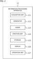
- Fig. 2 is a block diagram schematically illustrating the configuration of the information processing apparatus 12.
- the information processing apparatus 12 includes an acquisition unit 121, a generator 122, an adder 123, a creation unit 124, a storage 125, a display 126, and an operation unit 127.
- the acquisition unit 121 acquires the external signal and the captured image synchronized with the external signal from the imaging device 11.
- the generator 122 generates information regarding the external signal on the basis of the external signal.
- the adder 123 adds the information regarding the external signal to the captured image synchronized with the external signal.
- the adder 123 may combine the captured image synchronized with the external signal with the information regarding the external signal.
- the creation unit 124 creates a moving image including a plurality of captured images continuous in time series on the basis of the captured image to which the information regarding the external signal has been added.
- the storage 125 stores the moving image created by the creation unit 124.
- the display 126 displays the moving image created by the creation unit 124 or the moving image stored in the storage 125.
- the operation unit 127 is a controller that instructs the information processing apparatus 12 and operates the information processing apparatus 12.
- the acquisition unit 121 When the CPU of the information processing apparatus 12 executes a program stored in the storage 125, the acquisition unit 121, the generator 122, the adder 123, and the creation unit 124 perform predetermined processing. At least two of the acquisition unit 121, the generator 122, the adder 123, and the creation unit 124 may be integrated.
- the storage 125 includes a RAM and a nonvolatile storage device (e.g., ROM, flash memory, hard disk, etc.).
- the display 126 is, for example, a CRT (cathode ray tube) display, a liquid crystal display, a plasma display, an organic EL (Electro Luminescence) display, or the like.
- the operation unit 127 may include input devices such as a keyboard, a mouse, operation buttons, and a touch panel. Not all the components of the information processing apparatus 12 illustrated in Fig. 2 are essential, and components of the information processing apparatus 12 may be added or deleted as appropriate.
- Fig. 3 is a flowchart illustrating a flow of processing of the information processing apparatus 12.
- the processing illustrated in Fig. 3 is started when the information processing apparatus 12 receives a recording instruction.
- the recording is a process of creating a moving image including a plurality of captured images continuous in time series.
- Examples of the recording instruction include a constant recording instruction and a trigger recording instruction.
- the constant recording is a process of recording in a set time. In the constant recording, for example, a moving image including a plurality of captured images from time A to time B is created.
- the trigger recording is a process of starting recording when the setting condition is satisfied.
- a moving image that includes a plurality of captured images in a predetermined time (e.g., 5 minutes) before and after the timing at which the setting condition is satisfied is created.
- recording may be started when the amount of change between a plurality of captured images continuous in time series becomes equal to or greater than a threshold value.
- a preset still image and a captured image are compared, and recording may be started when the amount of change becomes equal to or greater than a threshold value.
- the information processing apparatus 12 acquires an external signal from the imaging device 11 (S1).
- the information processing apparatus 12 acquires a captured image synchronized with the external signal from the imaging device 11 (S2).
- the information processing apparatus 12 generates information regarding the external signal (S3).
- the information processing apparatus 12 adds the information regarding the external signal to the captured image synchronized with the external signal (S4).
- the information processing apparatus 12 determines whether or not it is the recording end timing (S5). When it is the recording end timing (S5; YES), the information processing apparatus 12 creates a moving image including a plurality of captured images continuous in time series on the basis of the captured image to which the information regarding the external signal has been added (S6). When it is not the recording end timing (S5; NO), the process returns to S1.
- the information processing apparatus 12 adds information regarding an external signal output from one signal output device 10 (e.g., signal output device 10A) to a captured image to create a moving image.
- the imaging device 11A acquires an external signal from the signal output device 10A connected to the imaging device 11A, and synchronously outputs a captured image and the external signal (the external signal output from the signal output device 10A).
- the information processing apparatus 12 acquires the captured image and the external signal from the imaging device 11A.
- the information processing apparatus 12 adds information regarding the external signal to a captured image synchronized with the external signal, and creates a moving image including a plurality of captured images continuous in time series on the basis of the captured image to which the information regarding the external signal has been added.
- the moving image includes a plurality of captured images output from the imaging device 11A, and the information regarding the external signal output from the signal output device 10A has been added to the captured images included in the moving image.
- the user can grasp the state of the external signal output from the signal output device 10A by viewing the moving image and checking the information regarding the external signal added to the captured image. Since the captured image and the external signal are synchronized with each other, the user can grasp the timing at which the state of the external signal output from the signal output device 10A changes. This makes it possible to reduce the time required for investigating the cause and performing recovery work when a problem occurs.
- the information processing apparatus 12 adds information regarding external signals output from a plurality of signal output devices 10 (e.g., signal output devices 10A to 10C) to a captured image to create a moving image.
- the imaging device 11A acquires external signals from the signal output devices 10A to 10C connected to the imaging device 11A, and synchronously outputs a captured image and a plurality of external signals (the external signals output from the signal output devices 10A to 10C).
- the information processing apparatus 12 acquires the captured image and the plurality of external signals from the imaging device 11A.
- the information processing apparatus 12 adds information regarding the plurality of external signals to the captured image synchronized with the plurality of external signals, and creates a moving image including a plurality of captured images continuous in time series on the basis of the captured image to which the information regarding the external signal has been added.
- the moving image includes a plurality of captured images output from the imaging device 11A, and the information regarding the external signals output from the signal output devices 10A to 10C has been added to the captured images included in the moving image.
- the user can grasp the state of the external signal output from each of the signal output devices 10A to 10C by viewing the moving image and checking the information regarding the plurality of external signal added to the captured image. This makes it possible to reduce the time required for investigating the cause and performing recovery work when a problem occurs, and to conduct complex analysis.
- the imaging device 11A acquires an external signal from the signal output device 10A connected to the imaging device 11A, and synchronously outputs a captured image and the external signal (the external signal output from the signal output device 10A).
- the imaging device 11B acquires an external signal from the signal output device 10D connected to the imaging device 11B, and synchronously outputs a captured image and the external signal (the external signal output from the signal output device 10D).
- the imaging device 11C acquires an external signal from the signal output device 10G connected to the imaging device 11C, and synchronously outputs a captured image and the external signal (the external signal output from the signal output device 10G).
- the information processing apparatus 12 acquires the captured image and the external signal (the external signal output from the signal output device 10A) from the imaging device 11A.
- the information processing apparatus 12 acquires the captured image and the external signal (the external signal output from the signal output device 10D) from the imaging device 11B.
- the information processing apparatus 12 acquires the captured image and the external signal (the external signal output from the signal output device 10G) from the imaging device 11C. In this manner, the information processing apparatus 12 acquires the captured images and external signals from the imaging devices 11A to 11C.
- the information processing apparatus 12 adds information regarding the external signals output from the signal output devices 10A, 10D, 10G to the captured image synchronized with the external signal output from one of the signal output devices 10A, 10D, 10G.
- the information processing apparatus 12 creates a moving image including a plurality of captured images continuous in time series on the basis of the captured image to which the information regarding the external signal output from the signal output devices 10A, 10D, 10G has been added. Therefore, the information regarding the external signals output from the signal output devices 10A, 10D, 10G has been added to the captured image included in the moving image.
- the moving image includes a plurality of captured images output from the imaging device 11A.
- the moving image includes a plurality of captured images output from the imaging device 11B.
- the moving image includes a plurality of captured images output from the imaging device 11C.
- the user can grasp the states of the external signals output from the signal output devices 10A, 10D, 10G by viewing the moving image and checking information regarding the plurality of external signals added to the captured image. This makes it possible to reduce the time required for investigating the cause and performing recovery work when a problem occurs, and to conduct complex analysis.
- the user can grasp the states of the external signals output from the signal output devices 10A, 10D, 10G by viewing a moving image including a plurality of captured images output from the imaging device 11A.
- the user can grasp the state of the external signal output from the signal output device 10A connected to the imaging device 11A, the state of the external signal output from the signal output device 10D connected to the imaging device 11B, and the state of the external signal output from the signal output device 10G connected to the imaging device 11C.
- the imaging device 11A acquires external signals from the signal output devices 10A to 10C connected to the imaging device 11A, and synchronously outputs a captured image and a plurality of external signals (the external signals output from the signal output devices 10A to 10C).
- the imaging device 11 B acquires external signals from the signal output devices 10D to 10F connected to the imaging device 11B, and synchronously outputs a captured image and a plurality of external signals (the external signals output from the signal output devices 10D to 10F).
- the imaging device 11C acquires external signals from the signal output devices 10G to 10J connected to the imaging device 11C, and synchronously outputs a captured image and a plurality of external signals (the external signals output from the signal output devices 10G to 10J).
- the information processing apparatus 12 acquires a captured image and the plurality of external signals (the external signals output from the signal output devices 10A to 10C) from the imaging device 11A.
- the information processing apparatus 12 acquires a captured image and the plurality of external signals (the external signals output from the signal output devices 10D to 10F) from the imaging device 11B.
- the information processing apparatus 12 acquires a captured image and the plurality of external signals (the external signals output from the signal output devices 10G to 10J) from the imaging device 11C. In this manner, the information processing apparatus 12 acquires the captured image and the plurality of external signals from each of the imaging devices 11A to 11C.
- the information processing apparatus 12 adds information regarding the external signals output from the signal output devices 10A to 10J to the captured image synchronized with the external signal output from one of the signal output devices 10A to 10J.
- the information processing apparatus 12 creates a moving image including a plurality of captured images continuous in time series on the basis of the captured image to which the information regarding the external signal output from the signal output devices 10A to 10J has been added. Therefore, information regarding the external signals output from the signal output devices 10A to 10J has been added to the captured image included in the moving image.
- the moving image includes a plurality of captured images output from the imaging device 11A.
- the moving image includes a plurality of captured images output from the imaging device 11B.
- the moving image includes a plurality of captured images output from the imaging device 11C.
- the user can grasp the states of the external signals output from the signal output devices 10A to 10J by viewing the moving image and checking information regarding the plurality of external signals added to the captured image. This makes it possible to reduce the time required for investigating the cause and performing recovery work when a problem occurs, and to conduct complex analysis.
- the user can grasp the states of the external signals output from the signal output devices 10A to 10J by viewing a moving image including a plurality of captured images output from the imaging device 11A.
- the user can grasp the states of the external signals output from the signal output devices 10A to 10C connected to the imaging device 11A, the states of the external signals output from the signal output devices 10D to 10F connected to the imaging device 11B, and the states of the external signals output from the signal output devices 10G to 10J connected to the imaging device 11C.
- the imaging devices 11A to 11C may set time information in the captured image.
- the information processing apparatus 12 may add information regarding the external signals output from the signal output devices 10A to 10J to the captured image synchronized with the external signal output from one of the signal output devices 10A to 10J by using time information set in the captured image. An example of a process of adding information regarding each external signal to a captured image synchronized with the external signal will be described.
- the information processing apparatus 12 acquires an external signal A1 and a captured image A2 synchronized with the external signal A1 from the imaging device 11A.
- the information processing apparatus 12 acquires an external signal B1 and a captured image B2 synchronized with the external signal B1 from the imaging device 11B.
- the information processing apparatus 12 acquires an external signal C1 and a captured image C2 synchronized with the external signal C1 from the imaging device 11C.
- the information processing apparatus 12 may add information regarding the external signal A1, information regarding the external signal B1, and information regarding the external signal C1 to the captured image A2 synchronized with the external signal A1 by using the time information set in the captured images A2, B2, C2.
- the information processing apparatus 12 may add information regarding the external signal A1, information regarding the external signal B1, and information regarding the external signal C1 to the captured image B2 synchronized with the external signal B1 by using the time information set in the captured images A2, B2, C2.
- the information processing apparatus 12 may add information regarding the external signal A1, information regarding the external signal B1, and information regarding the external signal C1 to the captured image C2 synchronized with the external signal C1 by using the time information set in the captured images A2, B2, C2.
- Fig. 4 is a diagram illustrating an example of the captured image.
- Fig. 4 illustrates a captured image when a robot 200 and a conveyor 300 are imaged.
- the robot 200 includes a robot arm 201 that performs predetermined work on a workpiece conveyed by the conveyor 300.
- the workpiece is, for example, a final product, an intermediate product, a semi-product, a part, a material, or the like.
- the imaging device 11A is performing imaging, and sensors 211 to 213 are connected to the imaging device 11A.
- the sensor 211 is a monitoring sensor that monitors the motion of the robot arm 201.
- the sensor 211 detects that the motion of the robot arm 201 is abnormal.
- the sensor 211 outputs an ON signal as an external signal.
- the sensor 211 falls within the predetermined range, the sensor 211 outputs an OFF signal as an external signal.
- the sensor 211 may be a current clamp attached to a cable line of an indicating lamp of a monitoring device that monitors the motion of the robot arm 201.
- a monitoring device that monitors the motion of the robot arm 201.
- the motion range of the robot arm 201 exceeds the predetermined range, current flows through the indicating lamp, and the indicating lamp is illuminated.
- the motion range of the robot arm 201 falls within the predetermined range, no current flows through the indicating lamp, and the indicating lamp is not illuminated.
- the sensor 211 outputs an ON signal as an external signal.
- no current flows through the indicating lamp the sensor 211 outputs an OFF signal as an external signal.
- the sensor 212 is a sensor that detects an abnormality in the conveyor 300. When the conveyor 300 is abnormal, the sensor 212 outputs an ON signal as an external signal. When the conveyor 300 is normal, the sensor 212 outputs an OFF signal as an external signal. For example, when detecting an abnormal sound from the conveyor 300, the sensor 212 detects that the conveyor 300 is abnormal.
- the sensor 212 may be a current clamp attached to a cable line of an indicating lamp of a detection device that detects an abnormality in the conveyor 300.
- the sensor 212 When the conveyor 300 is abnormal, current flows through the indicating lamp, and the indicating lamp is illuminated.
- the sensor 212 When the conveyor 300 is normal, no current flows through the indicating lamp, and the indicating lamp is not illuminated.
- the sensor 212 When current flows through the indicating lamp, the sensor 212 outputs an ON signal as an external signal.
- the sensor 212 outputs an OFF signal as an external signal.
- the sensor 213 is a vibration sensor that measures the vibration of the robot arm 201.
- the sensor 213 is installed near the base of the robot arm 201. When the measured vibration value does not fall within the predetermined range, the sensor 213 outputs an ON signal as an external signal. When the measured vibration value falls within the predetermined range, the sensor 213 outputs the OFF signal as an external signal.
- the imaging device 11A acquires the external signals output from the sensors 211 to 213.
- the imaging device 11A synchronously outputs a captured image and the external signal acquired from the sensors 211 to 213.
- the information processing apparatus 12 acquires the captured image and the external signals output from the imaging device 11A.
- the information processing apparatus 12 generates information regarding the external signals, and adds information regarding the external signals to the captured image synchronized with the external signals.
- the information regarding the external signals is superimposed on a predetermined area of the captured image.
- the captured image to which the information regarding the external signals has been added is displayed on the display 126 of the information processing apparatus 12.
- the information processing apparatus 12 may transmit the captured image to which the information regarding the external signals has been added to an external display apparatus, and the external display apparatus may display the captured image to which the information regarding the external signal has been added.
- the information regarding the external signals includes "Sensor 211: OFF”, “Sensor 212: OFF”, and "Sensor 213: ON”.
- the information regarding the external signals may include characters, numbers, and a time chart.
- the user can grasp the states of the external signals output from the sensors 211 to 213 by viewing the moving image using the information processing apparatus 12 or the external display apparatus and checking the information regarding the external signals added to the captured image. Since the captured image and the external signals are synchronized with each other, the user can grasp the timing at which the states of the external signals output from the sensors 211 to 213 change. For example, the user can grasp the timing at which the external signal of the sensor 213 changes from OFF to ON. This makes it possible to grasp the status of the equipment at the manufacturing site, and to reduce the time required for investigating the cause and performing recovery work when a problem occurs.
- Fig. 6 is a diagram illustrating an example of the captured image.
- Fig. 6 illustrates a captured image when the inside of a clean room is imaged.
- a precision equipment 400 and a particle sensor 401 are installed in the clean room.
- the particle sensor 401 detects a particle count in the clean room.
- Sensors 411 to 414 are provided in the precision equipment 400.
- the imaging device 11C is performing imaging, and sensors 411 to 414 are connected to the imaging device 11C.
- the sensor 411 is a sensor that detects the opening and closing of the door of precision equipment 400.
- the sensor 411 is, for example, a proximity sensor. When the door of the precision equipment 400 is open, the sensor 411 outputs an ON signal as an external signal. When the door of the precision equipment 400 is closed, the sensor 411 outputs an OFF signal as an external signal.
- the sensor 412 is a temperature sensor that measures the temperature in the precision equipment 400. When the temperature in the precision equipment 400 does not fall within a predetermined range, the sensor 412 outputs an ON signal as an external signal. When the temperature in the precision equipment 400 falls within the predetermined range, the sensor 412 outputs an OFF signal as an external signal.
- the sensor 413 is a humidity sensor that measures humidity in the precision equipment 400. When the humidity in the precision equipment 400 does not fall within a predetermined range, the sensor 413 outputs an ON signal as an external signal. When the humidity in the precision equipment 400 falls within the predetermined range, the sensor 413 outputs an OFF signal as an external signal.
- the sensor 414 is a vibration sensor that measures the vibration of the precision equipment 400. When the measured vibration value does not fall within a predetermined range, the sensor 414 outputs an ON signal as an external signal. When the measured vibration value falls within the predetermined range, the sensor 414 outputs the OFF signal as an external signal.
- the imaging device 11C acquires the external signals output from the sensors 411 to 414.
- the imaging device 11C outputs a captured image and the external signals acquired from the sensors 411 to 414 in synchronization with each other.
- the information processing apparatus 12 acquires the captured image and the external signal outputs from the imaging device 11C.
- the information processing apparatus 12 generates information regarding the external signals, and adds information regarding the external signals to the captured image synchronized with the external signals.
- information regarding external signals is superimposed on a predetermined area of the captured image.
- the captured image to which the information regarding the external signals has been added is displayed on the display 126 of the information processing apparatus 12.
- the information processing apparatus 12 may transmit the captured image to which the information regarding the external signals has been added to an external display apparatus, and the external display apparatus may display the captured image to which the information regarding the external signal has been added.
- the particle sensor 401 when the particle sensor 401 has detected a particle count equal to or greater than the threshold value, by analyzing the captured image illustrated in Fig. 6 , it can be inferred that the cause of the increase in a particle count in the clean room is the precision equipment 400.
- "Sensor 411: ON”, “Sensor 412: OFF”, “Sensor 413: ON”, and “Sensor 414: OFF” have been added to the captured image illustrated in Fig. 6 . Since “Sensor 411: ON” and “Sensor 413: ON” have been added to the captured image illustrated in Fig. 6 , the user can grasp that the door of the precision equipment 400 is open and the humidity in the precision equipment 400 does not fall within the predetermined range. In addition to the fact that the door of the precision equipment 400 is not closed, the user can consider that the humidity in the precision equipment 400 outside the predetermined range is the cause of the increase in a particle count in the clean room.
- the user can grasp the states of the external signals output from the sensors 411 to 414 by viewing the moving image using the information processing apparatus 12 or the external display apparatus and checking the information regarding the external signals added to the captured image. Since the captured image and the external signal are synchronized with each other, the user can grasp the timing at which the state of each of the external signals output from the sensors 411 to 414 changes. For example, the user can grasp the timing at which the external signal of the sensor 411 changes from OFF to ON and the timing at which the external signal of the sensor 413 changes from OFF to ON. This makes it possible to grasp the status of the equipment at the manufacturing site, and to reduce the time required for investigating the cause and performing recovery work when a problem occurs.
- each process described above may be regarded as an information processing method of the information processing system 1 or the like.
- Each process described above may be regarded as a method executed by a computer.
- a program for causing a computer to execute each process described above may be provided to the computer through a network or from a computer-readable recording medium or the like that holds data non-temporarily. Note that each of the above methods and processes can be combined with each other as much as possible to constitute the present invention.
- An information processing system (1) including:
Landscapes
- Engineering & Computer Science (AREA)
- Business, Economics & Management (AREA)
- Human Resources & Organizations (AREA)
- Strategic Management (AREA)
- Economics (AREA)
- Physics & Mathematics (AREA)
- General Physics & Mathematics (AREA)
- Signal Processing (AREA)
- Multimedia (AREA)
- Entrepreneurship & Innovation (AREA)
- Manufacturing & Machinery (AREA)
- Theoretical Computer Science (AREA)
- Marketing (AREA)
- Quality & Reliability (AREA)
- Tourism & Hospitality (AREA)
- General Business, Economics & Management (AREA)
- Game Theory and Decision Science (AREA)
- Operations Research (AREA)
- Educational Administration (AREA)
- Development Economics (AREA)
- Health & Medical Sciences (AREA)
- General Health & Medical Sciences (AREA)
- Primary Health Care (AREA)
- General Engineering & Computer Science (AREA)
- Automation & Control Theory (AREA)
- Studio Devices (AREA)
- Closed-Circuit Television Systems (AREA)
- Management, Administration, Business Operations System, And Electronic Commerce (AREA)
- General Factory Administration (AREA)
Abstract
Description
- The present invention relates to an information processing system.
- At a manufacturing site, equipment stoppage directly leads to loss, and hence, early investigation of the cause and early recovery from the stoppage are required. However, since the timing at which equipment stoppage occurs is unknown, a camera may be used to monitor equipment constantly, but constant monitoring is not very realistic in terms of resources (time and storage capacity).
- A technique is known to facilitate confirmation of an event by combining data from the event detected by a camera with a video feed captured by another (cf. Patent Document 1). In addition, a factory drive recorder has been developed as a tool to assist verification at a manufacturing site. Compared to a typical drive recorder, the factory drive recorder can record at higher resolution and frame rate, and can perform spot recording when a change occurs or with an input from an external signal as a trigger. The factory drive recorder can be retrofitted with a camera and other equipment, making it possible to monitor a problem that is difficult to anticipate during the design phase of the manufacturing line. The factory drive recorder is thus suitable for verification at the manufacturing site.
- Patent Document 1:
Japanese Unexamined Patent Publication No. 2018-98778 - The factory drive recorder can record a video of the manufacturing site by triggering a signal from an external sensor connected to the camera, thus enabling an operator to grasp a work status when a problem occurs by checking the video. However, if the status of equipment at the manufacturing site is unknown even though the video was checked, it takes time to investigate the cause and perform recovery work when the problem occurs.
- The present invention has been made in view of the above circumstances, and an object of the present invention is to provide a technique capable of reducing the time required for investigating the cause and performing recovery work when a problem occurs.
- An information processing system according to one aspect of the present invention is an information processing system including: a signal output unit configured to output an external signal; an imaging unit configured to acquire the external signal from the signal output unit and synchronously output a captured image generated by imaging an object and the external signal; and a creation unit configured to acquire the captured image and the external signal from the imaging unit, add information regarding the external signal to the captured image synchronized with the external signal, and create a moving image including a plurality of the captured images continuous in time series on the basis of the captured image to which the information regarding the external signal has been added.
- A user can grasp the state of the external signal output from the signal output device by viewing the moving image and checking the information regarding the external signal added to the captured image. Since the captured image and the external signal are synchronized with each other, the user can grasp the timing at which the state of the external signal output from the signal output device changes. This makes it possible to reduce the time required for investigating the cause and performing recovery work when a problem occurs.
- In the present invention, the signal output unit may one of a plurality of the signal output units, the imaging unit may acquire the external signal from each of the plurality of signal output units and output the captured image and a plurality of the external signals in synchronization with each other, and the creation unit may acquire the captured image and the plurality of external signals from the imaging unit, add information regarding the plurality of external signals to the captured image synchronized with the plurality of external signals, and create a moving image including a plurality of the captured images continuous in time series on the basis of the captured image to which the information regarding the plurality of external signals has been added. The user can grasp the state of the external signal output from each of the plurality of signal output devices by viewing the moving image and checking the information regarding the plurality of external signal added to the captured image.
- In the present invention, the signal output unit may be one of a plurality of the signal output units, the imaging unit may be one of a plurality of the imaging units, the plurality of imaging units may each acquire the external signals from the signal output units connected to each of the imaging units, and output the captured image and the external signals in synchronization with each other, and the creation unit may acquire the captured image and the external signals from each of the plurality of imaging units, add information regarding the external signals output from the plurality of signal output units to the captured image synchronized with the external signals output from one of the plurality of signal output units, and create a moving image including a plurality of the captured images continuous in time series on the basis of the captured image to which the information regarding the plurality of external signals has been added. The user can grasp the state of the external signal output from each of the plurality of signal output devices by viewing the moving image and checking the information regarding the plurality of external signal added to the captured image.
- In the present invention, the signal output unit may be one of a plurality of the signal output units, the imaging unit may be one of a plurality of the imaging units, the plurality of imaging units may each acquire the external signals from the plurality of signal output units connected to each of the imaging units, and output the captured image and the a plurality of the external signals in synchronization with each other, and the creation unit may acquire the captured image and the plurality of external signals from each of the plurality of imaging units, add information regarding the external signals output from the plurality of signal output units to the captured image synchronized with the external signals output from one of the plurality of signal output units, and create a moving image including a plurality of the captured images continuous in time series on the basis of the captured image to which the information regarding the plurality of external signals has been added. The user can grasp the state of the external signal output from each of the plurality of signal output devices by viewing the moving image and checking the information regarding the plurality of external signal added to the captured image.
- In the present invention, the signal output unit may be a sensor or a PLC. In the present invention, at least one of the plurality of signal output units may be a sensor, and at least one of the plurality of signal output units may be a PLC. In the present invention, the information regarding the external signal may include at least one of a letter, a number, a symbol, a character string, a number string, a graph, a time chart, and an icon.
- According to the present invention, it is possible to reduce the time required for investigating the cause and performing recovery work when a problem occurs.
-
- [
Fig. 1] Fig. 1 is a diagram illustrating a schematic configuration of an information processing system. - [
Fig. 2] Fig. 2 is a block diagram schematically illustrating a configuration of an information processing apparatus. - [
Fig. 3] Fig. 3 is a flowchart illustrating a flow of the processing of the information processing apparatus. - [
Fig. 4] Fig. 4 is a view illustrating an example of a captured image. - [
Fig. 5] Fig. 5 is a diagram illustrating an example of information regarding an external signal. - [
Fig. 6] Fig. 6 is a view illustrating an example of the captured image. - Hereinafter, application examples of the present invention will be described with reference to the drawings. As illustrated in
Fig. 1 , aninformation processing system 1 according to the present application example includes a plurality of signal output devices 10 (10A to 10J), a plurality of imaging devices 11 (11A to 11C), and aninformation processing apparatus 12. Thesignal output device 10 is an example of a signal output unit. Theimaging device 11 is an example of an imaging unit. Theinformation processing system 1 is employed at a manufacturing site, for example. In the configuration example illustrated inFig. 1 , thesignal output devices 10A to 10C are connected to theimaging device 11A, the signal output devices 10D to 10F are connected to theimaging device 11B, and thesignal output devices 10G to 10J are connected to theimaging device 11C. Theimaging devices 11A to 11C are connected to theinformation processing apparatus 12. - In the configuration example illustrated in
Fig. 1 , thesignal output devices 10A to 10C are connected to theimaging device 11A, but the number ofsignal output devices 10 connected to theimaging device 11A is not limited to three, and may be one, two, or four or more. In the configuration example illustrated inFig. 1 , the signal output devices 10D to 10F are connected to theimaging device 11B, but the number ofsignal output devices 10 connected to theimaging device 11B is not limited to three, and may be one, two, or four or more. In the configuration example illustrated inFig. 1 , thesignal output devices 10G to 10J are connected to theimaging device 11C, but the number ofsignal output devices 10 connected to theimaging device 11C is not limited to four, and may be one, two, three, or five or more. In the configuration example illustrated inFig. 1 , theimaging devices 11A to 11C are connected to theinformation processing apparatus 12, but the number of theimaging devices 11 connected to theinformation processing apparatus 12 is not limited to three, and may be one, two, or four or more. - The
signal output device 10 is a particle sensor, an image sensor, a flow rate sensor, a pressure sensor, a photoelectric sensor, a proximity sensor, a safety sensor (e.g., safety light curtain), a PLC (programmable logic controller), or the like. Thesignal output device 10 outputs an external signal. Thesignal output device 10 may be a sensor that performs sensing for obtaining various information in the surroundings and outputs an external signal according to the sensing result. Thesignal output device 10 may be a controller that acquires sensing results from various sensors, controls a control target, and outputs an external signal according to the sensing results. Thesignal output device 10 and theimaging device 11 are connected in a wired or wireless manner. Theimaging device 11 acquires the external signal output from thesignal output device 10. When the plurality ofsignal output devices 10 is connected to theimaging device 11, theimaging device 11 acquires external signals output from the plurality ofsignal output devices 10. - The
imaging device 11 is a camera that images an object and generates a captured image. Theimaging device 11 may be an industrial camera. Theimaging device 11 generates a captured image at a predetermined frame rate. Theimaging device 11 synchronously outputs a captured image and the external signal acquired from thesignal output device 10. When the plurality ofsignal output devices 10 are connected to theimaging device 11, theimaging device 11 synchronously outputs a captured image and the plurality of external signals acquired from the plurality ofsignal output devices 10. Theimaging device 11 and theinformation processing apparatus 12 are connected to each other in a wired or wireless manner. Theinformation processing apparatus 12 acquires the captured image and the external signal output from theimaging device 11. The external signal output from thesignal output device 10 is input to theinformation processing apparatus 12 via theimaging device 11. As a result, theinformation processing apparatus 12 can easily acquire the external signal and the captured image synchronized with the external signal. - The
information processing apparatus 12 may include a computer including, for example, a CPU (processor), a RAM, a nonvolatile storage device (e.g., ROM, flash memory, hard disk, etc.), an I/O interface, and the like. Theinformation processing apparatus 12 may be, for example, a processing device such as a personal computer (PC), an industrial personal computer (IPC), an embedded computer, a smartphone, or a tablet terminal. All or some of the functions provided by theinformation processing apparatus 12 may include a circuit such as an ASIC or a FPGA. Alternatively, theinformation processing apparatus 12 may perform predetermined processing in cooperation with another computer using a distributed computing or cloud computing technique. - The
information processing apparatus 12 adds information regarding the external signal to the captured image synchronized with the external signal. Theinformation processing apparatus 12 may combine the captured image synchronized with the external signal with the information regarding the external signal. When acquiring a plurality of external signals from theimaging device 11, theinformation processing apparatus 12 adds information regarding the plurality of external signals to the captured image. The information regarding the external signal may be information indicating the state of the external signal. The information regarding the external signal includes at least one of a letter, a number, a symbol, a character string, a number string, a graph, a time chart, and an icon. Theinformation processing apparatus 12 creates a moving image including a plurality of captured images continuous in time series on the basis of the captured image to which the information regarding the external signal has been added. - The user can grasp the state of the external signal output from the
signal output device 10 by viewing the moving image (video) and checking the information regarding the external signal added to the captured image. Since the captured image and the external signal are synchronized with each other, the user can grasp the timing at which the state of the external signal output from thesignal output device 10 changes. This makes it possible to reduce the time required for investigating the cause and performing recovery work when a problem occurs. -
Fig. 2 is a block diagram schematically illustrating the configuration of theinformation processing apparatus 12. Theinformation processing apparatus 12 includes anacquisition unit 121, agenerator 122, anadder 123, acreation unit 124, astorage 125, adisplay 126, and anoperation unit 127. Theacquisition unit 121 acquires the external signal and the captured image synchronized with the external signal from theimaging device 11. Thegenerator 122 generates information regarding the external signal on the basis of the external signal. Theadder 123 adds the information regarding the external signal to the captured image synchronized with the external signal. Theadder 123 may combine the captured image synchronized with the external signal with the information regarding the external signal. Thecreation unit 124 creates a moving image including a plurality of captured images continuous in time series on the basis of the captured image to which the information regarding the external signal has been added. Thestorage 125 stores the moving image created by thecreation unit 124. Thedisplay 126 displays the moving image created by thecreation unit 124 or the moving image stored in thestorage 125. Theoperation unit 127 is a controller that instructs theinformation processing apparatus 12 and operates theinformation processing apparatus 12. - When the CPU of the
information processing apparatus 12 executes a program stored in thestorage 125, theacquisition unit 121, thegenerator 122, theadder 123, and thecreation unit 124 perform predetermined processing. At least two of theacquisition unit 121, thegenerator 122, theadder 123, and thecreation unit 124 may be integrated. Thestorage 125 includes a RAM and a nonvolatile storage device (e.g., ROM, flash memory, hard disk, etc.). Thedisplay 126 is, for example, a CRT (cathode ray tube) display, a liquid crystal display, a plasma display, an organic EL (Electro Luminescence) display, or the like. Theoperation unit 127 may include input devices such as a keyboard, a mouse, operation buttons, and a touch panel. Not all the components of theinformation processing apparatus 12 illustrated inFig. 2 are essential, and components of theinformation processing apparatus 12 may be added or deleted as appropriate. -
Fig. 3 is a flowchart illustrating a flow of processing of theinformation processing apparatus 12. The processing illustrated inFig. 3 is started when theinformation processing apparatus 12 receives a recording instruction. The recording is a process of creating a moving image including a plurality of captured images continuous in time series. Examples of the recording instruction include a constant recording instruction and a trigger recording instruction. The constant recording is a process of recording in a set time. In the constant recording, for example, a moving image including a plurality of captured images from time A to time B is created. The trigger recording is a process of starting recording when the setting condition is satisfied. In the trigger recording, a moving image that includes a plurality of captured images in a predetermined time (e.g., 5 minutes) before and after the timing at which the setting condition is satisfied is created. In trigger recording, recording may be started when the amount of change between a plurality of captured images continuous in time series becomes equal to or greater than a threshold value. In addition, in the trigger recording, a preset still image and a captured image are compared, and recording may be started when the amount of change becomes equal to or greater than a threshold value. - The
information processing apparatus 12 acquires an external signal from the imaging device 11 (S1). Theinformation processing apparatus 12 acquires a captured image synchronized with the external signal from the imaging device 11 (S2). Theinformation processing apparatus 12 generates information regarding the external signal (S3). Theinformation processing apparatus 12 adds the information regarding the external signal to the captured image synchronized with the external signal (S4). Theinformation processing apparatus 12 determines whether or not it is the recording end timing (S5). When it is the recording end timing (S5; YES), theinformation processing apparatus 12 creates a moving image including a plurality of captured images continuous in time series on the basis of the captured image to which the information regarding the external signal has been added (S6). When it is not the recording end timing (S5; NO), the process returns to S1. - A description will be given of an example in which the
information processing apparatus 12 adds information regarding an external signal output from one signal output device 10 (e.g.,signal output device 10A) to a captured image to create a moving image. Theimaging device 11A acquires an external signal from thesignal output device 10A connected to theimaging device 11A, and synchronously outputs a captured image and the external signal (the external signal output from thesignal output device 10A). - The
information processing apparatus 12 acquires the captured image and the external signal from theimaging device 11A. Theinformation processing apparatus 12 adds information regarding the external signal to a captured image synchronized with the external signal, and creates a moving image including a plurality of captured images continuous in time series on the basis of the captured image to which the information regarding the external signal has been added. In this case, the moving image includes a plurality of captured images output from theimaging device 11A, and the information regarding the external signal output from thesignal output device 10A has been added to the captured images included in the moving image. The user can grasp the state of the external signal output from thesignal output device 10A by viewing the moving image and checking the information regarding the external signal added to the captured image. Since the captured image and the external signal are synchronized with each other, the user can grasp the timing at which the state of the external signal output from thesignal output device 10A changes. This makes it possible to reduce the time required for investigating the cause and performing recovery work when a problem occurs. - A description will be given of an example in which the
information processing apparatus 12 adds information regarding external signals output from a plurality of signal output devices 10 (e.g.,signal output devices 10A to 10C) to a captured image to create a moving image. Theimaging device 11A acquires external signals from thesignal output devices 10A to 10C connected to theimaging device 11A, and synchronously outputs a captured image and a plurality of external signals (the external signals output from thesignal output devices 10A to 10C). Theinformation processing apparatus 12 acquires the captured image and the plurality of external signals from theimaging device 11A. - The
information processing apparatus 12 adds information regarding the plurality of external signals to the captured image synchronized with the plurality of external signals, and creates a moving image including a plurality of captured images continuous in time series on the basis of the captured image to which the information regarding the external signal has been added. In this case, the moving image includes a plurality of captured images output from theimaging device 11A, and the information regarding the external signals output from thesignal output devices 10A to 10C has been added to the captured images included in the moving image. The user can grasp the state of the external signal output from each of thesignal output devices 10A to 10C by viewing the moving image and checking the information regarding the plurality of external signal added to the captured image. This makes it possible to reduce the time required for investigating the cause and performing recovery work when a problem occurs, and to conduct complex analysis. - A description will be given of an example in which the
information processing apparatus 12 adds information regarding external signals output from a plurality of signal output devices 10 (e.g.,signal output devices imaging device 11A acquires an external signal from thesignal output device 10A connected to theimaging device 11A, and synchronously outputs a captured image and the external signal (the external signal output from thesignal output device 10A). Theimaging device 11B acquires an external signal from the signal output device 10D connected to theimaging device 11B, and synchronously outputs a captured image and the external signal (the external signal output from the signal output device 10D). Theimaging device 11C acquires an external signal from thesignal output device 10G connected to theimaging device 11C, and synchronously outputs a captured image and the external signal (the external signal output from thesignal output device 10G). - The
information processing apparatus 12 acquires the captured image and the external signal (the external signal output from thesignal output device 10A) from theimaging device 11A. Theinformation processing apparatus 12 acquires the captured image and the external signal (the external signal output from the signal output device 10D) from theimaging device 11B. Theinformation processing apparatus 12 acquires the captured image and the external signal (the external signal output from thesignal output device 10G) from theimaging device 11C. In this manner, theinformation processing apparatus 12 acquires the captured images and external signals from theimaging devices 11A to 11C. - The
information processing apparatus 12 adds information regarding the external signals output from thesignal output devices signal output devices information processing apparatus 12 creates a moving image including a plurality of captured images continuous in time series on the basis of the captured image to which the information regarding the external signal output from thesignal output devices signal output devices - In the case of adding the information regarding the external signals output from the
signal output devices signal output device 10A, the moving image includes a plurality of captured images output from theimaging device 11A. In the case of adding the information regarding the external signals output from thesignal output devices imaging device 11B. In the case of adding the information regarding the external signals output from thesignal output devices signal output device 10G, the moving image includes a plurality of captured images output from theimaging device 11C. - The user can grasp the states of the external signals output from the
signal output devices - For example, the user can grasp the states of the external signals output from the
signal output devices imaging device 11A. In this manner, by viewing one moving image, the user can grasp the state of the external signal output from thesignal output device 10A connected to theimaging device 11A, the state of the external signal output from the signal output device 10D connected to theimaging device 11B, and the state of the external signal output from thesignal output device 10G connected to theimaging device 11C. - A description will be given of an example in which the
information processing apparatus 12 adds information regarding external signals output from a plurality of signal output devices 10 (e.g.,signal output devices 10A to 10J) to a captured image to create a moving image. Theimaging device 11A acquires external signals from thesignal output devices 10A to 10C connected to theimaging device 11A, and synchronously outputs a captured image and a plurality of external signals (the external signals output from thesignal output devices 10A to 10C). Theimaging device 11 B acquires external signals from the signal output devices 10D to 10F connected to theimaging device 11B, and synchronously outputs a captured image and a plurality of external signals (the external signals output from the signal output devices 10D to 10F). Theimaging device 11C acquires external signals from thesignal output devices 10G to 10J connected to theimaging device 11C, and synchronously outputs a captured image and a plurality of external signals (the external signals output from thesignal output devices 10G to 10J). - The
information processing apparatus 12 acquires a captured image and the plurality of external signals (the external signals output from thesignal output devices 10A to 10C) from theimaging device 11A. Theinformation processing apparatus 12 acquires a captured image and the plurality of external signals (the external signals output from the signal output devices 10D to 10F) from theimaging device 11B. Theinformation processing apparatus 12 acquires a captured image and the plurality of external signals (the external signals output from thesignal output devices 10G to 10J) from theimaging device 11C. In this manner, theinformation processing apparatus 12 acquires the captured image and the plurality of external signals from each of theimaging devices 11A to 11C. - The
information processing apparatus 12 adds information regarding the external signals output from thesignal output devices 10A to 10J to the captured image synchronized with the external signal output from one of thesignal output devices 10A to 10J. Theinformation processing apparatus 12 creates a moving image including a plurality of captured images continuous in time series on the basis of the captured image to which the information regarding the external signal output from thesignal output devices 10A to 10J has been added. Therefore, information regarding the external signals output from thesignal output devices 10A to 10J has been added to the captured image included in the moving image. - In the case of adding the information regarding the external signals output from the
signal output devices 10A to 10J to the captured image synchronized with the external signal output from one of thesignal output devices 10A to 10C, the moving image includes a plurality of captured images output from theimaging device 11A. In the case of adding the information regarding the external signals output from thesignal output devices 10A to 10J to the captured image synchronized with the external signal output from one of the signal output devices 10D to 10F, the moving image includes a plurality of captured images output from theimaging device 11B. In the case of adding the information regarding the external signals output from thesignal output devices 10A to 10J to the captured image synchronized with the external signal output from one of thesignal output devices 10G to 10J, the moving image includes a plurality of captured images output from theimaging device 11C. - The user can grasp the states of the external signals output from the
signal output devices 10A to 10J by viewing the moving image and checking information regarding the plurality of external signals added to the captured image. This makes it possible to reduce the time required for investigating the cause and performing recovery work when a problem occurs, and to conduct complex analysis. - For example, the user can grasp the states of the external signals output from the
signal output devices 10A to 10J by viewing a moving image including a plurality of captured images output from theimaging device 11A. In this manner, by viewing one moving image, the user can grasp the states of the external signals output from thesignal output devices 10A to 10C connected to theimaging device 11A, the states of the external signals output from the signal output devices 10D to 10F connected to theimaging device 11B, and the states of the external signals output from thesignal output devices 10G to 10J connected to theimaging device 11C. - The
imaging devices 11A to 11C may set time information in the captured image. Theinformation processing apparatus 12 may add information regarding the external signals output from thesignal output devices 10A to 10J to the captured image synchronized with the external signal output from one of thesignal output devices 10A to 10J by using time information set in the captured image. An example of a process of adding information regarding each external signal to a captured image synchronized with the external signal will be described. Theinformation processing apparatus 12 acquires an external signal A1 and a captured image A2 synchronized with the external signal A1 from theimaging device 11A. Theinformation processing apparatus 12 acquires an external signal B1 and a captured image B2 synchronized with the external signal B1 from theimaging device 11B. Theinformation processing apparatus 12 acquires an external signal C1 and a captured image C2 synchronized with the external signal C1 from theimaging device 11C. - The
information processing apparatus 12 may add information regarding the external signal A1, information regarding the external signal B1, and information regarding the external signal C1 to the captured image A2 synchronized with the external signal A1 by using the time information set in the captured images A2, B2, C2. Theinformation processing apparatus 12 may add information regarding the external signal A1, information regarding the external signal B1, and information regarding the external signal C1 to the captured image B2 synchronized with the external signal B1 by using the time information set in the captured images A2, B2, C2. Theinformation processing apparatus 12 may add information regarding the external signal A1, information regarding the external signal B1, and information regarding the external signal C1 to the captured image C2 synchronized with the external signal C1 by using the time information set in the captured images A2, B2, C2. -
Fig. 4 is a diagram illustrating an example of the captured image.Fig. 4 illustrates a captured image when arobot 200 and aconveyor 300 are imaged. Therobot 200 includes arobot arm 201 that performs predetermined work on a workpiece conveyed by theconveyor 300. The workpiece is, for example, a final product, an intermediate product, a semi-product, a part, a material, or the like. Here, theimaging device 11A is performing imaging, andsensors 211 to 213 are connected to theimaging device 11A. - The
sensor 211 is a monitoring sensor that monitors the motion of therobot arm 201. When the motion range of therobot arm 201 exceeds a predetermined range, thesensor 211 detects that the motion of therobot arm 201 is abnormal. When the motion range of therobot arm 201 exceeds the predetermined range, thesensor 211 outputs an ON signal as an external signal. When the motion range of therobot arm 201 falls within the predetermined range, thesensor 211 outputs an OFF signal as an external signal. - The
sensor 211 may be a current clamp attached to a cable line of an indicating lamp of a monitoring device that monitors the motion of therobot arm 201. When the motion range of therobot arm 201 exceeds the predetermined range, current flows through the indicating lamp, and the indicating lamp is illuminated. When the motion range of therobot arm 201 falls within the predetermined range, no current flows through the indicating lamp, and the indicating lamp is not illuminated. When current flows through the indicating lamp, thesensor 211 outputs an ON signal as an external signal. When no current flows through the indicating lamp, thesensor 211 outputs an OFF signal as an external signal. - The
sensor 212 is a sensor that detects an abnormality in theconveyor 300. When theconveyor 300 is abnormal, thesensor 212 outputs an ON signal as an external signal. When theconveyor 300 is normal, thesensor 212 outputs an OFF signal as an external signal. For example, when detecting an abnormal sound from theconveyor 300, thesensor 212 detects that theconveyor 300 is abnormal. - The
sensor 212 may be a current clamp attached to a cable line of an indicating lamp of a detection device that detects an abnormality in theconveyor 300. When theconveyor 300 is abnormal, current flows through the indicating lamp, and the indicating lamp is illuminated. When theconveyor 300 is normal, no current flows through the indicating lamp, and the indicating lamp is not illuminated. When current flows through the indicating lamp, thesensor 212 outputs an ON signal as an external signal. When no current flows through the indicating lamp, thesensor 212 outputs an OFF signal as an external signal. - The
sensor 213 is a vibration sensor that measures the vibration of therobot arm 201. Thesensor 213 is installed near the base of therobot arm 201. When the measured vibration value does not fall within the predetermined range, thesensor 213 outputs an ON signal as an external signal. When the measured vibration value falls within the predetermined range, thesensor 213 outputs the OFF signal as an external signal. - The
imaging device 11A acquires the external signals output from thesensors 211 to 213. Theimaging device 11A synchronously outputs a captured image and the external signal acquired from thesensors 211 to 213. Theinformation processing apparatus 12 acquires the captured image and the external signals output from theimaging device 11A. Theinformation processing apparatus 12 generates information regarding the external signals, and adds information regarding the external signals to the captured image synchronized with the external signals. In the example of the captured image illustrated inFig. 4 , the information regarding the external signals is superimposed on a predetermined area of the captured image. The captured image to which the information regarding the external signals has been added is displayed on thedisplay 126 of theinformation processing apparatus 12. Furthermore, theinformation processing apparatus 12 may transmit the captured image to which the information regarding the external signals has been added to an external display apparatus, and the external display apparatus may display the captured image to which the information regarding the external signal has been added. - In the example of the captured image illustrated in
Fig. 4 , the information regarding the external signals includes "Sensor 211: OFF", "Sensor 212: OFF", and "Sensor 213: ON". As illustrated inFig. 5 , the information regarding the external signals may include characters, numbers, and a time chart. - For example, when a flaw with an unknown cause has occurred in the workpiece at the site where the
robot 200 is used, it can be inferred that the cause is around therobot arm 201 used during the processing by analyzing the captured image illustrated inFig. 4 . The user can check whether or not therobot 200 is in motion by viewing the captured image illustrated inFig. 4 . "Sensor 211: OFF", "Sensor 212: OFF", and "Sensor 213: ON" have been added to the captured image illustrated inFig. 4 . Since "Sensor 213: ON" has been added to the captured image illustrated inFig. 4 , the user can grasp that the vibration value measured by thesensor 213 does not fall within the predetermined range. The user can consider that the vibration of therobot arm 201 is out of the expected range to be the cause of the flaw on the workpiece. - The user can grasp the states of the external signals output from the
sensors 211 to 213 by viewing the moving image using theinformation processing apparatus 12 or the external display apparatus and checking the information regarding the external signals added to the captured image. Since the captured image and the external signals are synchronized with each other, the user can grasp the timing at which the states of the external signals output from thesensors 211 to 213 change. For example, the user can grasp the timing at which the external signal of thesensor 213 changes from OFF to ON. This makes it possible to grasp the status of the equipment at the manufacturing site, and to reduce the time required for investigating the cause and performing recovery work when a problem occurs. -
Fig. 6 is a diagram illustrating an example of the captured image.Fig. 6 illustrates a captured image when the inside of a clean room is imaged. Aprecision equipment 400 and aparticle sensor 401 are installed in the clean room. Theparticle sensor 401 detects a particle count in the clean room.Sensors 411 to 414 are provided in theprecision equipment 400. Here, theimaging device 11C is performing imaging, andsensors 411 to 414 are connected to theimaging device 11C. - The
sensor 411 is a sensor that detects the opening and closing of the door ofprecision equipment 400. Thesensor 411 is, for example, a proximity sensor. When the door of theprecision equipment 400 is open, thesensor 411 outputs an ON signal as an external signal. When the door of theprecision equipment 400 is closed, thesensor 411 outputs an OFF signal as an external signal. - The
sensor 412 is a temperature sensor that measures the temperature in theprecision equipment 400. When the temperature in theprecision equipment 400 does not fall within a predetermined range, thesensor 412 outputs an ON signal as an external signal. When the temperature in theprecision equipment 400 falls within the predetermined range, thesensor 412 outputs an OFF signal as an external signal. - The
sensor 413 is a humidity sensor that measures humidity in theprecision equipment 400. When the humidity in theprecision equipment 400 does not fall within a predetermined range, thesensor 413 outputs an ON signal as an external signal. When the humidity in theprecision equipment 400 falls within the predetermined range, thesensor 413 outputs an OFF signal as an external signal. - The
sensor 414 is a vibration sensor that measures the vibration of theprecision equipment 400. When the measured vibration value does not fall within a predetermined range, thesensor 414 outputs an ON signal as an external signal. When the measured vibration value falls within the predetermined range, thesensor 414 outputs the OFF signal as an external signal. - The
imaging device 11C acquires the external signals output from thesensors 411 to 414. Theimaging device 11C outputs a captured image and the external signals acquired from thesensors 411 to 414 in synchronization with each other. Theinformation processing apparatus 12 acquires the captured image and the external signal outputs from theimaging device 11C. Theinformation processing apparatus 12 generates information regarding the external signals, and adds information regarding the external signals to the captured image synchronized with the external signals. In the example of the captured image illustrated inFig. 6 , information regarding external signals is superimposed on a predetermined area of the captured image. The captured image to which the information regarding the external signals has been added is displayed on thedisplay 126 of theinformation processing apparatus 12. Furthermore, theinformation processing apparatus 12 may transmit the captured image to which the information regarding the external signals has been added to an external display apparatus, and the external display apparatus may display the captured image to which the information regarding the external signal has been added. - For example, when the
particle sensor 401 has detected a particle count equal to or greater than the threshold value, by analyzing the captured image illustrated inFig. 6 , it can be inferred that the cause of the increase in a particle count in the clean room is theprecision equipment 400. "Sensor 411: ON", "Sensor 412: OFF", "Sensor 413: ON", and "Sensor 414: OFF" have been added to the captured image illustrated inFig. 6 . Since "Sensor 411: ON" and "Sensor 413: ON" have been added to the captured image illustrated inFig. 6 , the user can grasp that the door of theprecision equipment 400 is open and the humidity in theprecision equipment 400 does not fall within the predetermined range. In addition to the fact that the door of theprecision equipment 400 is not closed, the user can consider that the humidity in theprecision equipment 400 outside the predetermined range is the cause of the increase in a particle count in the clean room. - The user can grasp the states of the external signals output from the
sensors 411 to 414 by viewing the moving image using theinformation processing apparatus 12 or the external display apparatus and checking the information regarding the external signals added to the captured image. Since the captured image and the external signal are synchronized with each other, the user can grasp the timing at which the state of each of the external signals output from thesensors 411 to 414 changes. For example, the user can grasp the timing at which the external signal of thesensor 411 changes from OFF to ON and the timing at which the external signal of thesensor 413 changes from OFF to ON. This makes it possible to grasp the status of the equipment at the manufacturing site, and to reduce the time required for investigating the cause and performing recovery work when a problem occurs. - Furthermore, each process described above may be regarded as an information processing method of the
information processing system 1 or the like. Each process described above may be regarded as a method executed by a computer. A program for causing a computer to execute each process described above may be provided to the computer through a network or from a computer-readable recording medium or the like that holds data non-temporarily. Note that each of the above methods and processes can be combined with each other as much as possible to constitute the present invention. - An information processing system (1) including:
- a signal output unit (10) that outputs an external signal;
- an imaging unit (11) that acquires the external signal from the signal output unit (10) and synchronously output a captured image generated by imaging an object and the external signal; and
- a creation unit (10, 124) that acquires the captured image and the external signal from the imaging unit (11), adds information regarding the external signal to the captured image synchronized with the external signal, and creates a moving image including a plurality of the captured images continuous in time series on the basis of the captured image to which the information regarding the external signal has been added.
-
- 1 information processing system
- 10 (10 to 10J) signal output device
- 11 (11A to 11C) imaging device
- 12 information processing apparatus
- 121 acquisition unit
- 122 generator
- 123 adder
- 124 creation unit
- 125 storage
- 126 display
- 127 operation unit
Claims (7)
- An information processing system comprising:a signal output unit configured to output an external signal;an imaging unit configured to acquire the external signal from the signal output unit and synchronously output a captured image generated by imaging an object and the external signal; anda creation unit configured to acquire the captured image and the external signal from the imaging unit, add information regarding the external signal to the captured image synchronized with the external signal, and create a moving image including a plurality of the captured images continuous in time series on a basis of the captured image to which the information regarding the external signal has been added.
- The information processing system according to claim 1, whereinthe signal output unit is one of a plurality of the signal output units,the imaging unit acquires the external signal from each of the plurality of signal output units and outputs the captured image and a plurality of the external signals in synchronization with each other, andthe creation unit acquires the captured image and the plurality of external signals from the imaging unit, adds information regarding the plurality of external signals to the captured image synchronized with the plurality of external signals, and creates a moving image including a plurality of the captured images continuous in time series on a basis of the captured image to which the information regarding the plurality of external signals has been added.
- The information processing system according to claim 1, whereinthe signal output unit is one of a plurality of the signal output units,the imaging unit is one of a plurality of the imaging units,the plurality of imaging units each acquires the external signals from the signal output units connected to each of the imaging units, and outputs the captured image and the external signals in synchronization with each other, andthe creation unit acquires the captured image and the external signals from each of the plurality of imaging units, adds information regarding the external signals output from the plurality of signal output units to the captured image synchronized with the external signals output from one of the plurality of signal output units, and creates a moving image including a plurality of the captured images continuous in time series on a basis of the captured image to which the information regarding the plurality of external signals has been added.
- The information processing system according to claim 1, whereinthe signal output unit is one of a plurality of the signal output units,the imaging unit is one of a plurality of the imaging units,the plurality of imaging units each acquires the external signals from the plurality of signal output units connected to each of the imaging units, and outputs the captured image and the plurality of external signals in synchronization with each other, andthe creation unit acquires the captured image and the plurality of external signals from each of the plurality of imaging units, adds information regarding the external signals output from the plurality of signal output units to the captured image synchronized with the external signals output from one of the plurality of signal output units, and creates a moving image including a plurality of the captured images continuous in time series on a basis of the captured image to which the information regarding the plurality of external signals has been added.
- The information processing system according to claim 1, wherein the signal output unit is a sensor or a PLC.
- The information processing system according to any one of claims 2 to 4, whereinat least one of the plurality of signal output units is a sensor, andat least one of the plurality of signal output units is a PLC.
- The information processing system according to any one of claims 1 to 6, wherein the information regarding the external signal includes at least one of a letter, a number, a symbol, a character string, a number string, a graph, a time chart, and an icon.
Applications Claiming Priority (2)
| Application Number | Priority Date | Filing Date | Title |
|---|---|---|---|
| JP2022010958A JP7753903B2 (en) | 2022-01-27 | 2022-01-27 | Information Processing Systems |
| PCT/JP2022/046909 WO2023145308A1 (en) | 2022-01-27 | 2022-12-20 | Information processing system |
Publications (1)
| Publication Number | Publication Date |
|---|---|
| EP4440101A1 true EP4440101A1 (en) | 2024-10-02 |
Family
ID=87471615
Family Applications (1)
| Application Number | Title | Priority Date | Filing Date |
|---|---|---|---|
| EP22924157.5A Withdrawn EP4440101A1 (en) | 2022-01-27 | 2022-12-20 | Information processing system |
Country Status (4)
| Country | Link |
|---|---|
| US (1) | US20250063144A1 (en) |
| EP (1) | EP4440101A1 (en) |
| JP (1) | JP7753903B2 (en) |
| WO (1) | WO2023145308A1 (en) |
Families Citing this family (1)
| Publication number | Priority date | Publication date | Assignee | Title |
|---|---|---|---|---|
| US20250131290A1 (en) * | 2023-10-18 | 2025-04-24 | Minitab, Llc | Identifying relevance of process inputs |
Family Cites Families (7)
| Publication number | Priority date | Publication date | Assignee | Title |
|---|---|---|---|---|
| US9589190B2 (en) * | 2012-12-21 | 2017-03-07 | Robert Bosch Gmbh | System and method for detection of high-interest events in video data |
| WO2016145443A1 (en) * | 2015-03-12 | 2016-09-15 | Daniel Kerzner | Virtual enhancement of security monitoring |
| GB2557597B (en) | 2016-12-09 | 2020-08-26 | Canon Kk | A surveillance apparatus and a surveillance method for indicating the detection of motion |
| JP7192243B2 (en) * | 2018-05-11 | 2022-12-20 | オムロン株式会社 | Analysis support device and analysis support method |
| JP2020071568A (en) * | 2018-10-30 | 2020-05-07 | キヤノンマーケティングジャパン株式会社 | Information processing system, information processing method, and program |
| JP7014133B2 (en) * | 2018-11-09 | 2022-02-01 | オムロン株式会社 | Information gathering system, information gathering method, self-propelled robot, information processing device and program |
| JP7055394B2 (en) * | 2019-06-11 | 2022-04-18 | 株式会社ユピテル | Systems and programs |
-
2022
- 2022-01-27 JP JP2022010958A patent/JP7753903B2/en active Active
- 2022-12-20 WO PCT/JP2022/046909 patent/WO2023145308A1/en not_active Ceased
- 2022-12-20 US US18/721,946 patent/US20250063144A1/en not_active Abandoned
- 2022-12-20 EP EP22924157.5A patent/EP4440101A1/en not_active Withdrawn
Also Published As
| Publication number | Publication date |
|---|---|
| JP7753903B2 (en) | 2025-10-15 |
| WO2023145308A1 (en) | 2023-08-03 |
| JP2023109442A (en) | 2023-08-08 |
| US20250063144A1 (en) | 2025-02-20 |
Similar Documents
| Publication | Publication Date | Title |
|---|---|---|
| EP3540546B1 (en) | Failure prediction support device, failure prediction support method and failure prediction support program | |
| US20230152771A1 (en) | Control device and image recording method | |
| WO2016143072A1 (en) | Programmable logic controller | |
| CN113767407A (en) | Information processing device, information processing method, information processing program, and recording medium | |
| US10789705B2 (en) | Quality monitoring system | |
| KR102483811B1 (en) | Abnormal status monitoring and controlling system for automated process | |
| EP3973364B1 (en) | System and method for determining a health condition and an anomaly of an equipment | |
| CN110058983B (en) | Abnormal inspection parameter adjustment display device | |
| WO2019216199A1 (en) | Analysis assistance device and analysis assistance method | |
| US20250063144A1 (en) | Information processing system | |
| WO2020026344A1 (en) | Abnormality determination device and abnormality determination method | |
| CN111989198B (en) | Abnormality detection device and abnormality detection method | |
| KR20170016437A (en) | Information Retrieval System and Method | |
| EP3617703B1 (en) | Computer readable program code and monitoring device for monitoring a state of a chromatography apparatus | |
| JP2015084176A (en) | Fault diagnostic apparatus and active machine | |
| US10955829B2 (en) | System and a method to enable zero defect production | |
| JP6898382B2 (en) | Support method for injection molding machine operation management | |
| US20220121191A1 (en) | Time-series data processing method | |
| KR20160141971A (en) | Plc apparatus | |
| KR101999781B1 (en) | Monitoring apparatus and method for monitoring device without supporting Internet of Thing | |
| JP6937251B2 (en) | Abnormal factor determination device, control system, and abnormal factor determination method | |
| KR20150110862A (en) | System for providing car repair technique | |
| CN119797184A (en) | A method, system and device for remotely operating a crane video delay detection alarm | |
| JPH0916250A (en) | Monitoring and control equipment | |
| JP2024040655A (en) | Failure prediction system and failure prediction method |
Legal Events
| Date | Code | Title | Description |
|---|---|---|---|
| STAA | Information on the status of an ep patent application or granted ep patent |
Free format text: STATUS: THE INTERNATIONAL PUBLICATION HAS BEEN MADE |
|
| PUAI | Public reference made under article 153(3) epc to a published international application that has entered the european phase |
Free format text: ORIGINAL CODE: 0009012 |
|
| STAA | Information on the status of an ep patent application or granted ep patent |
Free format text: STATUS: REQUEST FOR EXAMINATION WAS MADE |
|
| 17P | Request for examination filed |
Effective date: 20240626 |
|
| AK | Designated contracting states |
Kind code of ref document: A1 Designated state(s): AL AT BE BG CH CY CZ DE DK EE ES FI FR GB GR HR HU IE IS IT LI LT LU LV MC ME MK MT NL NO PL PT RO RS SE SI SK SM TR |
|
| DAV | Request for validation of the european patent (deleted) | ||
| DAX | Request for extension of the european patent (deleted) | ||
| STAA | Information on the status of an ep patent application or granted ep patent |
Free format text: STATUS: THE APPLICATION HAS BEEN WITHDRAWN |
|
| 18W | Application withdrawn |
Effective date: 20250812 |