EP4439972A1 - Cooling architecture for a cryogenic and superconducting powertrain using liquid hydrogen on board and method for managing the cooling temperature of the powertrain components - Google Patents
Cooling architecture for a cryogenic and superconducting powertrain using liquid hydrogen on board and method for managing the cooling temperature of the powertrain components Download PDFInfo
- Publication number
- EP4439972A1 EP4439972A1 EP24161407.2A EP24161407A EP4439972A1 EP 4439972 A1 EP4439972 A1 EP 4439972A1 EP 24161407 A EP24161407 A EP 24161407A EP 4439972 A1 EP4439972 A1 EP 4439972A1
- Authority
- EP
- European Patent Office
- Prior art keywords
- superconducting
- cryogenic
- powertrain
- fluid
- cooling
- Prior art date
- Legal status (The legal status is an assumption and is not a legal conclusion. Google has not performed a legal analysis and makes no representation as to the accuracy of the status listed.)
- Granted
Links
Images


Classifications
-
- H—ELECTRICITY
- H02—GENERATION; CONVERSION OR DISTRIBUTION OF ELECTRIC POWER
- H02K—DYNAMO-ELECTRIC MACHINES
- H02K55/00—Dynamo-electric machines having windings operating at cryogenic temperatures
-
- H—ELECTRICITY
- H02—GENERATION; CONVERSION OR DISTRIBUTION OF ELECTRIC POWER
- H02P—CONTROL OR REGULATION OF ELECTRIC MOTORS, ELECTRIC GENERATORS OR DYNAMO-ELECTRIC CONVERTERS; CONTROLLING TRANSFORMERS, REACTORS OR CHOKE COILS
- H02P29/00—Arrangements for regulating or controlling electric motors, appropriate for both AC and DC motors
- H02P29/60—Controlling or determining the temperature of the motor or of the drive
-
- B—PERFORMING OPERATIONS; TRANSPORTING
- B60—VEHICLES IN GENERAL
- B60L—PROPULSION OF ELECTRICALLY-PROPELLED VEHICLES; SUPPLYING ELECTRIC POWER FOR AUXILIARY EQUIPMENT OF ELECTRICALLY-PROPELLED VEHICLES; ELECTRODYNAMIC BRAKE SYSTEMS FOR VEHICLES IN GENERAL; MAGNETIC SUSPENSION OR LEVITATION FOR VEHICLES; MONITORING OPERATING VARIABLES OF ELECTRICALLY-PROPELLED VEHICLES; ELECTRIC SAFETY DEVICES FOR ELECTRICALLY-PROPELLED VEHICLES
- B60L58/00—Methods or circuit arrangements for monitoring or controlling batteries or fuel cells, specially adapted for electric vehicles
- B60L58/30—Methods or circuit arrangements for monitoring or controlling batteries or fuel cells, specially adapted for electric vehicles for monitoring or controlling fuel cells
- B60L58/32—Methods or circuit arrangements for monitoring or controlling batteries or fuel cells, specially adapted for electric vehicles for monitoring or controlling fuel cells for controlling the temperature of fuel cells, e.g. by controlling the electric load
- B60L58/33—Methods or circuit arrangements for monitoring or controlling batteries or fuel cells, specially adapted for electric vehicles for monitoring or controlling fuel cells for controlling the temperature of fuel cells, e.g. by controlling the electric load by cooling
-
- B—PERFORMING OPERATIONS; TRANSPORTING
- B64—AIRCRAFT; AVIATION; COSMONAUTICS
- B64D—EQUIPMENT FOR FITTING IN OR TO AIRCRAFT; FLIGHT SUITS; PARACHUTES; ARRANGEMENT OR MOUNTING OF POWER PLANTS OR PROPULSION TRANSMISSIONS IN AIRCRAFT
- B64D27/00—Arrangement or mounting of power plants in aircraft; Aircraft characterised by the type or position of power plants
- B64D27/02—Aircraft characterised by the type or position of power plants
- B64D27/30—Aircraft characterised by electric power plants
- B64D27/34—All-electric aircraft
-
- B—PERFORMING OPERATIONS; TRANSPORTING
- B64—AIRCRAFT; AVIATION; COSMONAUTICS
- B64D—EQUIPMENT FOR FITTING IN OR TO AIRCRAFT; FLIGHT SUITS; PARACHUTES; ARRANGEMENT OR MOUNTING OF POWER PLANTS OR PROPULSION TRANSMISSIONS IN AIRCRAFT
- B64D27/00—Arrangement or mounting of power plants in aircraft; Aircraft characterised by the type or position of power plants
- B64D27/02—Aircraft characterised by the type or position of power plants
- B64D27/30—Aircraft characterised by electric power plants
- B64D27/35—Arrangements for on-board electric energy production, distribution, recovery or storage
- B64D27/355—Arrangements for on-board electric energy production, distribution, recovery or storage using fuel cells
-
- B—PERFORMING OPERATIONS; TRANSPORTING
- B64—AIRCRAFT; AVIATION; COSMONAUTICS
- B64D—EQUIPMENT FOR FITTING IN OR TO AIRCRAFT; FLIGHT SUITS; PARACHUTES; ARRANGEMENT OR MOUNTING OF POWER PLANTS OR PROPULSION TRANSMISSIONS IN AIRCRAFT
- B64D33/00—Arrangement in aircraft of power plant parts or auxiliaries not otherwise provided for
- B64D33/08—Arrangement in aircraft of power plant parts or auxiliaries not otherwise provided for of power plant cooling systems
-
- B—PERFORMING OPERATIONS; TRANSPORTING
- B64—AIRCRAFT; AVIATION; COSMONAUTICS
- B64D—EQUIPMENT FOR FITTING IN OR TO AIRCRAFT; FLIGHT SUITS; PARACHUTES; ARRANGEMENT OR MOUNTING OF POWER PLANTS OR PROPULSION TRANSMISSIONS IN AIRCRAFT
- B64D37/00—Arrangements in connection with fuel supply for power plant
- B64D37/30—Fuel systems for specific fuels
-
- H—ELECTRICITY
- H01—ELECTRIC ELEMENTS
- H01M—PROCESSES OR MEANS, e.g. BATTERIES, FOR THE DIRECT CONVERSION OF CHEMICAL ENERGY INTO ELECTRICAL ENERGY
- H01M8/00—Fuel cells; Manufacture thereof
- H01M8/04—Auxiliary arrangements, e.g. for control of pressure or for circulation of fluids
- H01M8/04007—Auxiliary arrangements, e.g. for control of pressure or for circulation of fluids related to heat exchange
- H01M8/04067—Heat exchange or temperature measuring elements, thermal insulation, e.g. heat pipes, heat pumps, fins
-
- H—ELECTRICITY
- H01—ELECTRIC ELEMENTS
- H01M—PROCESSES OR MEANS, e.g. BATTERIES, FOR THE DIRECT CONVERSION OF CHEMICAL ENERGY INTO ELECTRICAL ENERGY
- H01M8/00—Fuel cells; Manufacture thereof
- H01M8/04—Auxiliary arrangements, e.g. for control of pressure or for circulation of fluids
- H01M8/04082—Arrangements for control of reactant parameters, e.g. pressure or concentration
- H01M8/04201—Reactant storage and supply, e.g. means for feeding, pipes
- H01M8/04208—Cartridges, cryogenic media or cryogenic reservoirs
-
- H—ELECTRICITY
- H02—GENERATION; CONVERSION OR DISTRIBUTION OF ELECTRIC POWER
- H02K—DYNAMO-ELECTRIC MACHINES
- H02K11/00—Structural association of dynamo-electric machines with electric components or with devices for shielding, monitoring or protection
- H02K11/30—Structural association with control circuits or drive circuits
- H02K11/33—Drive circuits, e.g. power electronics
-
- H—ELECTRICITY
- H02—GENERATION; CONVERSION OR DISTRIBUTION OF ELECTRIC POWER
- H02K—DYNAMO-ELECTRIC MACHINES
- H02K7/00—Arrangements for handling mechanical energy structurally associated with dynamo-electric machines, e.g. structural association with mechanical driving motors or auxiliary dynamo-electric machines
- H02K7/003—Couplings; Details of shafts
-
- H—ELECTRICITY
- H02—GENERATION; CONVERSION OR DISTRIBUTION OF ELECTRIC POWER
- H02K—DYNAMO-ELECTRIC MACHINES
- H02K9/00—Arrangements for cooling or ventilating
- H02K9/10—Arrangements for cooling or ventilating by gaseous cooling medium flowing in closed circuit, a part of which is external to the machine casing
-
- B—PERFORMING OPERATIONS; TRANSPORTING
- B60—VEHICLES IN GENERAL
- B60L—PROPULSION OF ELECTRICALLY-PROPELLED VEHICLES; SUPPLYING ELECTRIC POWER FOR AUXILIARY EQUIPMENT OF ELECTRICALLY-PROPELLED VEHICLES; ELECTRODYNAMIC BRAKE SYSTEMS FOR VEHICLES IN GENERAL; MAGNETIC SUSPENSION OR LEVITATION FOR VEHICLES; MONITORING OPERATING VARIABLES OF ELECTRICALLY-PROPELLED VEHICLES; ELECTRIC SAFETY DEVICES FOR ELECTRICALLY-PROPELLED VEHICLES
- B60L2200/00—Type of vehicles
- B60L2200/10—Air crafts
-
- H—ELECTRICITY
- H01—ELECTRIC ELEMENTS
- H01M—PROCESSES OR MEANS, e.g. BATTERIES, FOR THE DIRECT CONVERSION OF CHEMICAL ENERGY INTO ELECTRICAL ENERGY
- H01M2250/00—Fuel cells for particular applications; Specific features of fuel cell system
- H01M2250/20—Fuel cells in motive systems, e.g. vehicle, ship, plane
-
- Y—GENERAL TAGGING OF NEW TECHNOLOGICAL DEVELOPMENTS; GENERAL TAGGING OF CROSS-SECTIONAL TECHNOLOGIES SPANNING OVER SEVERAL SECTIONS OF THE IPC; TECHNICAL SUBJECTS COVERED BY FORMER USPC CROSS-REFERENCE ART COLLECTIONS [XRACs] AND DIGESTS
- Y02—TECHNOLOGIES OR APPLICATIONS FOR MITIGATION OR ADAPTATION AGAINST CLIMATE CHANGE
- Y02T—CLIMATE CHANGE MITIGATION TECHNOLOGIES RELATED TO TRANSPORTATION
- Y02T90/00—Enabling technologies or technologies with a potential or indirect contribution to GHG emissions mitigation
- Y02T90/40—Application of hydrogen technology to transportation, e.g. using fuel cells
Definitions
- the present invention relates to a cryogenic and superconducting powertrain using liquid hydrogen and having a cooling architecture, and also to a method for managing a cooling temperature of powertrain components.
- liquid hydrogen (LH 2 ) available on-board can be used to cool-down the components of the powertrain.
- LH 2 is not meant for direct use (i.e. for the direct cooling of electrical components).
- the amount of LH 2 flowing from the LH 2 tank to the fuel cell system for a given flight phase is limited and, in general, driven by the fuel cell needs itself.
- a current cryogenic and superconducting powertrain comprises at least the following elements:
- the different components of the cryogenic and superconducting powertrain have different cooling needs both in terms of maximum allowable temperature and maximum allowable temperature gradient across the components itself.
- the performances and the efficiency of the component itself depend on the temperature.
- Table 1 summarizes the maximum allowable temperature and maximum allowable temperature gradient of the components in the cryogenic and superconducting powertrain: Table 1: Maximum allowable temperature and maximum allowable temperature gradient of the components in the cryogenic and superconducting powertrain Component of the cryogenic and superconducting powertrain Maximum allowable temperature (Tmax) Maximum allowable temperature gradient Superconducting Motor 40K / Motor Control Unit (MCU) 120K 20K DC Line 75K / DC/DC Converter 140K 20K Main Current Leads 150K /
- the maximum allowable temperature gradient of the MCU (here 20K) shall not be exceeded to guarantee the proper operation of the MCU.
- the efficiency of the MCU depends on the temperature: the MCU has a better efficiency at a lower temperature than its Tmax (i.e. lower than 120K).
- the maximum allowable temperature gradient of the DC/DC Converter (here 20K) shall not be exceeded to guarantee the proper operation of the DC/DC Converter.
- the efficiency of the DC/DC Converter depends on the temperature: the DC/DC Converter has a better efficiency at a lower temperature than its Tmax (i.e. lower than 140K).
- the efficiency of the main Current Leads to the fuel cell depends on the temperature: the main Current Leads have a better efficiency at a lower temperature than its Tmax (i.e. lower than 150K). Hence, all components of the cryogenic powertrain do not have the same cooling needs, and thus do not need to be cooled at the same temperature, since each component does not have the same maximum allowable temperature.
- cryogenic and superconducting powertrain comprising:
- the first fluid comprises LH 2 and the second fluid comprises gaseous helium (GHe).
- the cooling architecture comprises a primary cooling loop for the first fluid and a secondary cooling loop for the second fluid.
- the secondary cooling loop is arranged and configured to cool down the cryogenic and superconducting powertrain components.
- the secondary cooling loop is cooled by LH 2 flow, and in return heats the LH 2 that will enter in the fuel cell.
- cryogenic and superconducting powertrain further comprising:
- the cooling architecture further comprises a second heat exchanger configured to exchange heat between the first fluid and the second fluid.
- the cooling architecture further comprises a third heat exchanger configured to exchange heat between the first fluid and a third fluid, the third fluid being a coolant of the Thermal Management System.
- the cooling architecture further comprises a third cryostat of second fluid for cooling the third heat exchanger.
- the third heat exchanger is configured to exchange heat between the first fluid of the first heat exchanger and the third fluid
- the cooling architecture further comprises a fourth heat exchanger configured to exchange heat between the first fluid of the second heat exchanger and the third fluid.
- the cooling architecture further comprises a fourth cryostat of second fluid for cooling the third heat exchanger.
- the cooling architecture further comprises a fifth cryostat of second fluid for cooling the cryogenic recirculation fan and the heat exchanger.
- the second cryostat of second fluid is further arranged for cooling the main current leads.
- the cooling architecture further comprises a sixth cryostat of second fluid for cooling the superconducting distribution and protection device.
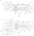
- Fig. 1 represents a cooling architecture for a cryogenic and superconducting powertrain (including a Superconducting Motor, Motor Control Units, a Superconducting distribution and protection and the cryogenic DC/DC conversion) operating at cryogenic temperature.
- a cryogenic and superconducting powertrain including a Superconducting Motor, Motor Control Units, a Superconducting distribution and protection and the cryogenic DC/DC conversion
- the cryogenic and superconducting powertrain 10 comprises:
- the cooling architecture 30 comprises:
- the cooling architecture 30 comprises a primary cooling loop 100 for LH 2 and a secondary cooling loop 102 for GHe.
- the secondary cooling loop 102 is arranged and configured to cool down the powertrain components.
- the secondary cooling loop 102 is cooled by LH 2 flow, and in return heats the LH 2 that will enter in the fuel cell 22.
- the cooling architecture 30 comprises a first heat exchanger 36a and a second heat exchanger 36b.
- Each heat exchanger 36a, 36b is configured to transfer heat from a first fluid to a second fluid.
- the first fluid of each heat exchanger 36a, 36b is liquid hydrogen (H 2 )
- the second fluid of each heat exchanger 36a, 36b is gaseous helium (He).
- the second fluid of the heat exchangers 36a, 36b may be another inert fluid than helium, for instance liquid Neon or liquid Nitrogen (N 2 ).
- gaseous helium is used in the secondary cooling loop 102, since it is less expensive than Neon, and it is an inert element, reducing the safety risk significantly compared to H 2 , and is lightweight. Moreover, helium is the only element with a boiling point lower than H 2 , so it will be in its gaseous phase in all the possible aircraft scenarios. This simplifies the global cooling architecture 30 for the cryogenic and superconducting powertrain 10, since no compressors and/or buffers need to be introduced in the architecture (which have an impact on the global weight of the cooling architecture and its reliability).
- the cooling architecture 30 also comprises:
- LH 2 is used for cooling the cryogenic and superconducting powertrain 10. This allows to facilitate the subsequent conditioning of H 2 (before injection into the fuel cell 22), since H 2 rejected by the cooling architecture 30 of the cryogenic and superconducting powertrain 10 will be at an intermediate temperature between the boil temperature (20K at atmospheric pressure) and the injection temperature (around 300K) into the fuel cells 22, reducing the needs in terms of electrical heaters for H 2 conditioning.
- Table 2 represents the operations at maximum power for a typical 1.1 MW cryogenic and superconducting powertrain 10: Table 2: Dissipation of each component of the cryogenic and superconducting powertrain 10. Components Dissipation Superconducting Motor 12 3100W Motor Control Unit 14 (two in the powertrain 10) 4800W each Superconducting distribution 20 (two in the powertrain 10) 30W each DC/DC converter 26 (two in the powertrain 10) 5400W each Current Leads 24 to Fuel Cells 22 (eight in the powertrain 10) 100W each Cryofan 44 500W Cryolines/cryostats 100W
- the superconducting motor 12 is dissipating 3100W in use of the superconducting and cryogenic powertrain 10. Such dissipation is advantageously extracted with the fluids (more precisely with helium cooled by H 2 ) flowing through the superconducting motor 12. Helium, firstly cooled by H 2 , is warmed up by the heat dissipating from the superconducting motor 12, allowing the superconducting motor 12 to stay at its stable working temperature, even if the superconducting motor 12 dissipates 3100W.
- H 2 Helium, firstly cooled by H 2 , is warmed up by the heat dissipating from the superconducting motor 12, allowing the superconducting motor 12 to stay at its stable working temperature, even if the superconducting motor 12 dissipates 3100W.
- the same principle applies to all components of the powertrain 10.
- Fig. 2 represents a cooling architecture 30 of a cryogenic and superconducting powertrain 10 in which all components of the powertrain 10 are cooled in series, in order to minimize the impact of the cooling lines.
- dotted boxes indicate a dedicated cryostat for the respective components which need to be maintained at low temperatures.
- the superconducting motor 12 and the MCUs are arranged in the same cryostat 38.
- Each superconducting distribution and protection device 20 is arranged in a dedicated cryostat 48a, 48b.
- the current leads 24 and a DC/DC converter 26 are arranged in a common cryostat 50a, 50b. More precisely, as represented in Fig.
- current leads 24 and the DC/DC converters 26 of the powertrain 10 are divided into two electric lines, each electric line of the current leads 24 and a DC/DC converter 26 is arranged in a dedicated cryostat 50a, 50b.
- the cryogenic fan 44 and the heat exchanger 36 are also arranged in a common cryostat 52.
- the temperature of H 2 at the H 2 inlet of the heat exchanger 36 may be between 10K and 30K (here around 21K)
- the temperature of H 2 at the H 2 outlet of the heat exchanger 36 i.e. on the LH 2 line 104 in direction to the fuel cells 22
- the flow of H 2 may be between 20 g/s and 40 g/s (here around 27.1g/s).
- the flow of helium may be between 90 g/s and 115 g/s (here around 103g/s).
- the temperature of helium between the cryogenic fan 44 and the input of the heat exchanger 36 (on the cryogenic insulated line 54f) may be between 60K and 80K (here around 70K).
- the temperature of helium between the output of the heat exchanger 36 and the superconducting motor 12 (on the cryogenic insulated line 54a) may be between 10K and 30K (here around 23K).
- the temperature of helium between the superconducting motor 12 and the MCUs 14 (on the cryogenic insulated line 54b) may be between 20K and 40K (here around 29K).
- the temperature of helium between the DC distribution 20 and the MCU 14 may be between 35K and 55K (here around 46K).
- the temperature of helium between the DC/DC converter 26 and the DC distribution 20 may be between 40K and 60K (here around 47K).
- the temperature of helium between the current leads 24 and the DC/DC converter 26 may be between 55K and 75K (here around 67K). Helium is then transmitted from the current leads 24 to the cryogenic fan 44 through the cryogenic insulated line 54g.
- a predetermined amount of second fluid is cooled at a predetermined temperature, using the first fluid, before being injected in the superconducting motor 12 of the powertrain 10.
- helium (He) is cooled at a temperature around 23K by hydrogen (H 2 ).
- the amount of second fluid to be cooled is calculated depending on the constraints coming from the powertrain 10. For example, the flow of He circulating from the heat exchanger 36 to the superconducting motor 12 is around 103 g/s.
- the main constraint is the maximum temperature gradient allowed by the DC/DC converter 26 (here 20K).
- the flow of He circulating through the whole powertrain 10, and thus through the DC/DC converter 26, is around 103 g/s.
- a method for managing the cooling temperature of the powertrain components comprises the steps of:
- the limiting parameters of the powertrain components are determined based on the technical features of said components. Tests can be realized to determine such limiting parameters.
- the superconducting motor 12 is the powertrain component having the most limiting of the limiting parameters.
- first flow and temperature for helium are calculated taking into account the limiting parameters of the superconducting motor 12.
- second flow and temperature for helium are calculated for each component of the powertrain 10.
- the second flow and temperature of helium are compared to the first flow and temperature of helium calculated for the superconducting motor 12 of the powertrain 10. If the second flow of helium is lower than the first flow of helium that has been calculated for the superconducting motor 12, the first flow of helium is selected, and no adjustment of flow of helium is realized.
- the second flow of helium is higher than the first flow of helium that has been calculated for the superconducting motor 12, the second flow of helium is selected so that the flow of helium is adjusted. If the second temperature of helium is higher than the first temperature of helium that has been calculated for the superconducting motor 12, the first temperature of helium is selected, and no adjustment of temperature of helium is realized. If the second temperature of helium is lower than the first temperature of helium that has been calculated for the superconducting motor 12, the second temperature of helium is selected so that the temperature of helium is adjusted.
- the flow and temperature of helium finally selected correspond to the flow and temperature of helium the most limiting for the cooling architecture 30.
- the lower temperature of helium, either firstly calculated or adjusted, is selected for the cooling architecture 30; and the higher flow of helium, either firstly calculated or adjusted, is selected for the cooling architecture 30.
- LH 2 at around 20K (21K in Fig. 2 ) stored in a pressurized tank 32 is used as a cooling source.
- a working fluid of gaseous helium (GHe) is used in a closed circuit to cool-down the electrical components of the cryogenic and superconducting powertrain 10.
- the flow of GHe in the closed circuit is regulated by a circulation fan 44 (also called cryofan or cryogenic fan). This flow of GHe is also regulated based on the cooling power requirements of the powertrain 10.
- a circulation fan 44 also called cryofan or cryogenic fan.
- This flow of GHe is also regulated based on the cooling power requirements of the powertrain 10.
- one GHe/LH 2 heat exchanger 36 is used.
- LH 2 enters at around 20K in the heat exchanger 36 from the LH 2 tank 32.
- warm GHe around 70K
- MCU Motor Control Unit 14
- DC/DC converter 26 and the main current leads 24 (CL) to the Fuel Cell 22 (FC) at the desired low temperature.
- GHe coming out from the superconducting motor 12 may also be used to cool-down the Direct Current (DC) line 20 and other components of the powertrain 10.
- DC Direct Current
- This cooling architecture 30 also comprises remote control valves 46 to regulate the flow in different components.
- a valve 46 is arranged on the LH 2 line 104.
- the cryostat 52 housing the cryogenic fan 44 and the heat exchanger 36 is equipped with rupture disks 56 and a non-return valve with spring 58 to allow an evacuation of the fluid of the cryostat 52.
- the functioning of the valves is not detailed here.
- GHe entering the superconducting motor 12 is at a first temperature between 15K and 30K (here around 23K), GHe is warmed by the superconducting motor 12 up to a second temperature between 20K and 35K (here around 29K), due to the dissipation of the superconducting motor 12.
- GHe then enters to the MCU 14, and is warmed by the MCU 14 to a third temperature between 35K and 55K (here around 46K), due to the dissipation of the MCU 14.
- GHe then enters to the DC line 20, and is warmed by the DC line 20 to a fourth temperature between 40K and 55K (here around 47K), due to the dissipation of the DC line 20.
- GHe then enters to the DC/DC converter 26, and is warmed by the DC/DC converter 26 to a fifth temperature between 55K and 75K (here around 67K), due to the dissipation of the DC/DC converter 26. Then, GHe enters to the current leads 24 to the fuel cell 22, and is warmed by said current leads 24, due to the dissipation of said current leads 24, before being cooled by the cryogenic fan 44 to a temperature between 60K and 80K (here around 70K). GHe then passes through the heat exchanger 36 to be cooled, thanks to LH 2 , to the first temperature.
- the cooling architecture 30 preferably comprises two heat exchangers He/H 2 36a, 36b.
- Cooling architecture with two heat exchangers In Fig. 3 , the cooling architecture 30 of a cryogenic powertrain 10 is presented for a single superconducting motor 12 with two channels.
- a single channel configuration refers to the cryogenic powertrain 10 with one superconducting electric motor 12 coupled with a single Motor Control Unit 14 (MCU), Direct Current (DC) cable 20, DC/DC converter 26 and current leads 24 to the fuel cell 22.
- MCU Motor Control Unit 14
- DC Direct Current
- the temperature of H 2 at the H 2 inlet may be between 15K and 30K (here around 21K)
- the temperature of H 2 at the H 2 outlet may be between 125K and 140K (here around 132K)
- the flow of H2 may be between 10 g/s and 20 g/s (here around 15.3g/s).
- the flow of helium may be between 65 g/s and 85 g/s (here around 76g/s).
- the temperature of helium between the cryogenic fan 44 and the heat exchangers 36a, 36b (on the cryogenic insulated line 54f) may be between 120K and 140K (here around 130K).
- the temperature of helium between the first heat exchanger 36a and the superconducting motor 12 (on the cryogenic insulated line 54j) may be between 10K and 30K (here around 23K).
- the temperature of helium between the second heat exchanger 36b and the MCU 14 (at the connection side of the superconducting motor 12 with the MCU 14, on the cryogenic insulated line 54k) may be between 90K and 120K (here around 105K).
- the temperature of helium between MCUs 14 may be between 80K and 100K (here around 90K).
- the temperature of helium between the DC distribution 20 and the MCU 14 (at the connection side of the superconducting motor 12 with the MCU 14, on the cryogenic insulated line 54h) may be between 35K and 55K (here around 45K).
- the MCUs 14 are connected between the DC line 20 and the DC/DC converter 26 through the cryogenic insulated line 106.
- the temperature of helium at the output of the DC/DC converter 26 (on the cryogenic insulated line 54d arranged between the DC/DC converter 26 and the DC line 20) may be between 100K and 120K (here around 110K).
- the temperature of helium between the cryogenic fan 44 and the current leads 24 (on the cryogenic insulated line 54g) may be between 122K and 142K (here around 128K).
- a predetermined amount of second fluid is cooled at a predetermined temperature, using the first fluid, before being injected in the superconducting motor 12 of the powertrain 10.
- helium (He) is cooled at a temperature around 23K by hydrogen (H 2 ).
- the amount of second fluid to be cooled is calculated depending on the constraints coming from the powertrain. For example, the flow of He circulating from the heat exchanger 36a, 36b to the superconducting motor 12 is around 76 g/s.
- the main constraint is the maximum temperature gradient allowed by the DC/DC converter 26 (here 20K).
- the flow of He circulating through the whole powertrain 10, and thus through the DC/DC converter 26, is around 76 g/s.
- LH 2 at around 20K (at 21K in Fig. 3 ) stored in a pressurized tank 32 is used as a cooling source.
- a working fluid of gaseous helium (GHe) is used in a closed circuit to cool-down the electrical components of the cryogenic and superconducting powertrain 10.
- the flow of GHe in the closed circuit is regulated by the cryogenic fan 44.
- the flow of GHe is also regulated based on the cooling power requirements of the powertrain 10.
- two separate GHe/LH 2 heat exchangers 36a, 36b are used, because for the superconducting motor 12, a low mass flow rate is needed, with much lower temperature inlet (about 20K, 23K in Fig. 3 ), whereas for the motor control unit 14 and DC/DC converter 26, high flow rate at comparatively higher temperature inlet (about 100K) is needed.
- LH 2 enters at around 20K in both the heat exchangers 36a, 36b.
- warm GHe around 150K (130K in Fig. 3 ) is cooled down to around 20K (23K in Fig. 3 ) by LH 2 .
- Cold GHe is then used to maintain the superconducting motor 12 at the desired low temperature.
- GHe coming out from the superconducting motor 12 may also be used to cool-down the Direct Current (DC) line 20 and other components of the powertrain 10 (as represented in Fig. 3 ).
- DC Direct Current
- This cooling architecture 30 comprises remote control valves 46 to regulate the flow in different components. For instance, in Fig. 3 , valves 46 are arranged on each LH 2 line 34 to the heat exchanger 36a, 36b, on the cryogenic insulated lines 54k, 54h. The functioning of the valves is not detailed here.
- GHe coming from the first heat exchanger 36a and entering the superconducting motor 12 is at a first temperature between 20K and 30K (here around 23K), GHe is warmed by the superconducting motor 12 up to a second temperature between 30K and 55K (here around 45K), due to the dissipation of the superconducting motor 12.
- GHe coming out from the superconducting motor 12 enters to the DC line 20, and is warmed by the DC line 20, due to the dissipation of the DC line 20.
- GHe coming from the MCU 14 and from the DC line 20 enters to the DC/DC converter 26 at a temperature between 100K and 120K (here around 110K), and is warmed by the DC/DC converter 26, due to the dissipation of the DC/DC converter 26.
- GHe coming from the second heat exchanger 36b is at a temperature between 95K and 115K (here around 105K).
- GHe coming out from the superconducting motor 12 (here around 45K) is melted with GHe coming from the second heat exchanger 36b (here around 105K) before entering the MCU 14.
- GHe enters to the MCU 14 at a temperature between 80K and 100K (here around 90K), and is warmed by the MCU 14, due to the dissipation of the MCU 14. Then, GHe enters to the current leads 24 to the fuel cell 22, and is warmed by said current leads 24 up to a temperature between 120K and 140K (here around 128K), due to the dissipation of said current leads 24. Then, GHe passes through the cryogenic fan 44, and through the heat exchangers 36a, 36b to be cooled from a temperature between 120K and 140K (here around 130K), thanks to LH 2 , to the first temperature.
- the cryogenic fan 44 and the heat exchangers 36a, 36b are arranged in a common cryostat 52.
- the heat exchangers 36a, 36b are arranged in a cryostat 52, near to the fuel cell 22, to reduce the weight of the cooling architecture 30.
- this cryostat 52 and fuel cell 22 are arranged close to each other, for instance at one or two meters one from the other.
- FIG. 4 shows a powertrain 10 comprising a single superconducting motor 12 with two separate electrical channels.
- two channels are used in order to omit the electrical dependency on a single channel.
- the powertrain 10 would be able to work, in a degraded mode.
- a gearbox 18 is used to control the rotating speed of the motor shaft, through the electric line 108. In this architecture, a reduction ratio of speed will be applied using a gearbox 18.
- a motor control unit 14 is required to control all the functioning aspects of the superconducting motor 12.
- a DC/DC converter 26 is used because the main current leads 24 and the DC cables 20 are working at different voltage levels. Fuel cells 22 in this architecture are used as a source of DC power supply.
- the superconducting motor 12 and the two MCUs 14 are arranged in a common cryostat 38.
- Each DC line 20 is arranged in a distinct cryostat 48a, 48b.
- the DC/DC converter 26 and the main currents leads 24 to the fuel cell 22 of the first electrical channel are arranged in a common cryostat 50a.
- the DC/DC converter 26 and the main currents leads 24 to the fuel cell 22 of the second electrical channel are arranged in a common cryostat 50b.
- the two heat exchangers 36a, 36b and the cryofan 44 are arranged in a common cryostat 52.
- cold H 2 is firstly used to cool helium, through first and second heat exchangers 36a, 36b, and then H 2 at an intermediate temperature (on the H 2 line 116) is used to cool the Thermal Management System (TMS) 60 coolant, with another heat exchanger 62 arranged in a "cold" box 64 (another cryostat).
- TMS Thermal Management System
- Warm H 2 is then used to feed the fuel cell 22.
- Warm H 2 passes from the heat exchanger 62 (via a H 2 line 118) through a manifold 68 to be divided into two H 2 lines 70a, 70b.
- Each H 2 line 70a, 70b is equipped with a PGM 72, and then connected to the fuel cells 22 through the H 2 line 114.
- Each main current leads 24 to the fuel cells 22 can be bypassed, through the bypass lines 110a, 110b.
- This cooling architecture 30 also comprises remote control valves 46 to regulate the flow in different components.
- a valve 46 is arranged on the LH 2 line 34, and on each LH 2 line 34 to the heat exchanger 36a, 36b, on the cryogenic insulated lines 54k, 54h, on the bypass lines 110a, 110b of the main current leads 24, on the coolant lines 112a, 112b from and to the TMS 60.
- the cryostat 64 housing the heat exchanger 62 is equipped with rupture disks 56 and a non-return valve with spring 58 to allow an evacuation of the fluid of the cryostat 64.
- a throttle valve 66 is arranged on the cryogenic insulated line 34 coming from the H 2 tank 32 to the heat exchangers 36a, 36b.
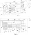
- Fig. 5A-5C show a cryogenic and superconducting powertrain 10 with two superconducting motors 12 with two electrical channels each, along with cross-links for the two cooling loops.
- Fig. 5B represents a box "motor assembly” 112a, 112b.
- Fig. 5C represents a box "heat exchanger assembly” 136a, 136b.
- the powertrain 10 comprises two superconducting motors 12 with two parallel electrical channels for each superconducting motor 12, and two cooling architectures 30.
- the two cooling architectures 30 are independent one from the other, but with cross-links between them in order to be able to continue to cool both superconducting motors 12 in case of a failure (of a fan 44 or a valve 46 for instance) or of LH 2 flow reduction (due to a fuel cell 22 failure).
- H 2 In a nominal situation, cold H 2 (coming from the H 2 tank 32 through the LH 2 line 34) entering the first "cold" box 74a (first cryostat) is used to cool He in the first heat exchanger assembly 136a. H 2 at an intermediate temperature results. Then, H 2 at an intermediate temperature (on the H 2 line 116a) is used to cool the TMS 60 coolant in the heat exchanger 62a. Resulting warm H 2 is then used to feed the fuel cell 22 of the first motor assembly 112a passing through a manifold 68 and PGM 72, and via the H 2 line 114.
- first "cold" box 74a first cryostat
- H 2 (coming from the H 2 tank 32) entering the second "cold" box 74b (second cryostat) is used to cool He in the second heat exchanger assembly 136b. H 2 at an intermediate temperature results. Then, H 2 at an intermediate temperature (on the H 2 line 116b) is used to cool the TMS 60 coolant in the heat exchanger 62b. Resulting warm H 2 is then used to feed the fuel cell 22 of the second motor assembly 112b.
- warm H 2 from either the first or second "cold" box 74a, 74b can be used to feed the fuel cell 22 of the first motor assembly 112a and the fuel cell 22 of the second motor assembly 122b.
- cross-links 76a, 76b are arranged on the H 2 circulation pipes 70a-d between the manifold 68 of the "cold" boxes 74a, 74b and the PGMs 72.
- H 2 circulation pipes 70a, 70b between the first "cold” box 74a and the PGMs 72 connected to the first motor assembly 112a comprise branching 76a, 76b to the H 2 circulation pipes 70c, 70d between the second "cold” box 74b and the PGMs 72 connected to the second motor assembly 112b.
- He from either the first or second heat exchanger assembly 136a, 136b can be used to cool the first motor assembly 112a and the second motor assembly 112b.
- cross-links 78a-c are arranged on the He circulation pipes 80a-b between the heat exchanger assemblies and the motor assemblies. More precisely, He circulation pipes between the first heat exchanger assembly and the first motor assembly comprise branching to the He circulation pipes between the second heat exchanger assembly and the second motor assembly.
- the powertrain comprises two superconducting motors with one electrical channel per superconducting motor, and two cooling architectures, with cross-links between the two cooling loops, to be able to use each cooling loop for both motors in a degraded mode.
- the systems and devices described herein may include a controller or a computing device comprising a processing and a memory which has stored therein computer-executable instructions for implementing the processes described herein.
- the processing unit may comprise any suitable devices configured to cause a series of steps to be performed so as to implement the method such that instructions, when executed by the computing device or other programmable apparatus, may cause the functions/acts/steps specified in the methods described herein to be executed.
- the processing unit may comprise, for example, any type of general-purpose microprocessor or microcontroller, a digital signal processing (DSP) processor, a central processing unit (CPU), an integrated circuit, a field programmable gate array (FPGA), a reconfigurable processor, other suitably programmed or programmable logic circuits, or any combination thereof.
- DSP digital signal processing
- CPU central processing unit
- FPGA field programmable gate array
- reconfigurable processor other suitably programmed or programmable logic circuits, or any combination thereof.
- the memory may be any suitable known or other machine-readable storage medium.
- the memory may comprise non-transitory computer readable storage medium such as, for example, but not limited to, an electronic, magnetic, optical, electromagnetic, infrared, or semiconductor system, apparatus, or device, or any suitable combination of the foregoing.
- the memory may include a suitable combination of any type of computer memory that is located either internally or externally to the device such as, for example, random-access memory (RAM), read-only memory (ROM), compact disc read-only memory (CDROM), electro-optical memory, magneto-optical memory, erasable programmable read-only memory (EPROM), and electrically-erasable programmable read-only memory (EEPROM), Ferroelectric RAM (FRAM) or the like.
- the memory may comprise any storage means (e.g., devices) suitable for retrievably storing the computer-executable instructions executable by processing unit.
- the methods and systems described herein may be implemented in a high-level procedural or object-oriented programming or scripting language, or a combination thereof, to communicate with or assist in the operation of the controller or computing device.
- the methods and systems described herein may be implemented in assembly or machine language.
- the language may be a compiled or interpreted language.
- Program code for implementing the methods and systems described herein may be stored on the storage media or the device, for example a ROM, a magnetic disk, an optical disc, a flash drive, or any other suitable storage media or device.
- the program code may be readable by a general or special-purpose programmable computer for configuring and operating the computer when the storage media or device is read by the computer to perform the procedures described herein.
- Computer-executable instructions may be in many forms, including modules, executed by one or more computers or other devices.
- modules include routines, programs, objects, components, data structures, etc., that perform particular tasks or implement particular abstract data types.
- functionality of the modules may be combined or distributed as desired in various embodiments.
Landscapes
- Engineering & Computer Science (AREA)
- Power Engineering (AREA)
- Aviation & Aerospace Engineering (AREA)
- Chemical & Material Sciences (AREA)
- Life Sciences & Earth Sciences (AREA)
- Sustainable Development (AREA)
- Sustainable Energy (AREA)
- Mechanical Engineering (AREA)
- Electrochemistry (AREA)
- General Chemical & Material Sciences (AREA)
- Chemical Kinetics & Catalysis (AREA)
- Manufacturing & Machinery (AREA)
- Combustion & Propulsion (AREA)
- Microelectronics & Electronic Packaging (AREA)
- Transportation (AREA)
- Containers, Films, And Cooling For Superconductive Devices (AREA)
Abstract
Description
- The present invention relates to a cryogenic and superconducting powertrain using liquid hydrogen and having a cooling architecture, and also to a method for managing a cooling temperature of powertrain components.
- Current cooling architectures for a cryogenic and superconducting powertrain are based on industrial cryocoolers specially made for ground applications. Cryocoolers made for ground applications cannot be used for aviation applications, since they do not have the cooling capacities necessary for aviation applications.
- In addition, there are also major concerns related to the weight and efficiency of such cryocoolers for aviation applications.
- On the other hand, liquid hydrogen (LH2) available on-board can be used to cool-down the components of the powertrain. However, due to safety reasons, in aviation applications, LH2 is not meant for direct use (i.e. for the direct cooling of electrical components).
- In addition, the amount of LH2 flowing from the LH2 tank to the fuel cell system for a given flight phase is limited and, in general, driven by the fuel cell needs itself.
- Therefore, an optimization of the cooling architecture is necessary in order to optimize the LH2 consumption and to meet the cooling needs of the powertrain with the LH2 flow available in a given flight phase.
- A current cryogenic and superconducting powertrain comprises at least the following elements:
- A Superconducting Motor,
- A Motor Control Unit (MCU), arranged to control the functioning aspects of the Superconducting Motor,
- A Direct Current (DC) Line,
- Main Current Leads (CL) to the Fuel Cells, and
- A DC/DC Converter arranged to adapt the voltage levels between the DC Line and the Main Current Leads.
- The different components of the cryogenic and superconducting powertrain have different cooling needs both in terms of maximum allowable temperature and maximum allowable temperature gradient across the components itself. In addition, the performances and the efficiency of the component itself depend on the temperature.
- Table 1 summarizes the maximum allowable temperature and maximum allowable temperature gradient of the components in the cryogenic and superconducting powertrain:
Table 1: Maximum allowable temperature and maximum allowable temperature gradient of the components in the cryogenic and superconducting powertrain Component of the cryogenic and superconducting powertrain Maximum allowable temperature (Tmax) Maximum allowable temperature gradient Superconducting Motor 40K / Motor Control Unit (MCU) 120K 20K DC Line 75K / DC/DC Converter 140K 20K Main Current Leads 150K / - According to Table 1, if the superconducting motor is exposed to a temperature above 40K (its Tmax), a risk of quench within the superconducting motor appears. Moreover, the efficiency of the superconducting motor depends on the temperature: the superconducting motor has a better efficiency at lower temperature than its Tmax (i.e. lower than 40K).
- The maximum allowable temperature gradient of the MCU (here 20K) shall not be exceeded to guarantee the proper operation of the MCU. Moreover, the efficiency of the MCU depends on the temperature: the MCU has a better efficiency at a lower temperature than its Tmax (i.e. lower than 120K).
- If the DC line is exposed to a temperature above 75K (its Tmax), a risk of quench appears within the DC line.
- The maximum allowable temperature gradient of the DC/DC Converter (here 20K) shall not be exceeded to guarantee the proper operation of the DC/DC Converter. Moreover, the efficiency of the DC/DC Converter depends on the temperature: the DC/DC Converter has a better efficiency at a lower temperature than its Tmax (i.e. lower than 140K).
- The efficiency of the main Current Leads to the fuel cell depends on the temperature: the main Current Leads have a better efficiency at a lower temperature than its Tmax (i.e. lower than 150K). Hence, all components of the cryogenic powertrain do not have the same cooling needs, and thus do not need to be cooled at the same temperature, since each component does not have the same maximum allowable temperature.
- Thus, there is a need for a method and system for managing the cooling temperature of each component of the cryogenic and superconducting powertrain.
- To this end, it is proposed a cryogenic and superconducting powertrain comprising:
- at least a superconducting e-motor, including a motor shaft,
- at least a motor control unit configured to control all functioning aspects of the superconducting e-motor,
- a propeller lead by the superconducting e-motor,
- a gearbox, arranged between the superconducting e-motor and the propeller, and configured to control a rotating speed of the motor shaft,
- at least a superconducting distribution and protection device,
- at least a fuel cell, which comprises a DC power supply,
- main current leads to the fuel cell,
- at least a DC/DC converter to adapt voltage levels between the superconducting distribution and protection device and the main current leads, wherein the main current leads and the superconducting distribution and protection device have different working voltage levels,
- a Thermal Management System (TMS) for managing the temperature of the fuel cell, and,
- a cooling architecture comprising:
- a liquid hydrogen (LH2) tank for LH2 storage at cryogenic temperature,
- LH2 circulation pipes starting and ending at the LH2 tank,
- a first heat exchanger configured to exchange heat between a first fluid and a second fluid,
- a first cryostat of second fluid for cooling the motor control unit and the superconducting e-motor,
- a second cryostat of second fluid for cooling the DC/DC converter, and
- second fluid circulation pipes, starting and ending at each cryostat.
- According to an embodiment of the invention, the first fluid comprises LH2 and the second fluid comprises gaseous helium (GHe).
- According to an embodiment of the invention, the cooling architecture comprises a primary cooling loop for the first fluid and a secondary cooling loop for the second fluid.
- According to an embodiment of the invention, the secondary cooling loop is arranged and configured to cool down the cryogenic and superconducting powertrain components.
- According to an embodiment of the invention, the secondary cooling loop is cooled by LH2 flow, and in return heats the LH2 that will enter in the fuel cell.
- According to an embodiment of the invention, the cryogenic and superconducting powertrain further comprising:
- a cryogenic recirculation fan in order to recirculate the second fluid into the cryogenic and superconducting powertrain components in a complete closed loop, and
- cryogenic insulated lines, in order to convey the cryogenic fluid to the electrical components of the cryogenic and superconducting powertrain.
- According to an embodiment of the invention, the cooling architecture further comprises a second heat exchanger configured to exchange heat between the first fluid and the second fluid.
- According to an embodiment of the invention, the cooling architecture further comprises a third heat exchanger configured to exchange heat between the first fluid and a third fluid, the third fluid being a coolant of the Thermal Management System.
- According to an embodiment of the invention, the cooling architecture further comprises a third cryostat of second fluid for cooling the third heat exchanger.
- According to an embodiment of the invention, the third heat exchanger is configured to exchange heat between the first fluid of the first heat exchanger and the third fluid, and the cooling architecture further comprises a fourth heat exchanger configured to exchange heat between the first fluid of the second heat exchanger and the third fluid.
- According to an embodiment of the invention, the cooling architecture further comprises a fourth cryostat of second fluid for cooling the third heat exchanger.
- According to an embodiment of the invention, the cooling architecture further comprises a fifth cryostat of second fluid for cooling the cryogenic recirculation fan and the heat exchanger.
- According to an embodiment of the invention, the second cryostat of second fluid is further arranged for cooling the main current leads.
- According to an embodiment of the invention, the cooling architecture further comprises a sixth cryostat of second fluid for cooling the superconducting distribution and protection device.
- It is also proposed a method for managing a cooling temperature of cryogenic and superconducting powertrain components of the cryogenic and superconducting powertrain components of the invention, comprising the steps of:
- determining limiting parameters of each component of the cryogenic and superconducting powertrain, said limiting parameters being a maximum allowable temperature and/or a maximum temperature gradient of each component of the cryogenic and superconducting powertrain,
- calculating a flow and temperature of a fluid passing through the superconducting e-motor which is necessary to respect the limiting parameters of the superconducting e-motor, and
- adjusting the flow and temperature of a fluid circulating through the whole cryogenic and superconducting powertrain which is necessary to respect the other limiting parameters, knowing the flow and temperature of said fluid through the superconducting e-motor .
- The characteristics of the invention mentioned above, as well as others, will appear more clearly on reading the following description of at least one embodiment, said description being made in relation to the attached drawings, among which:
-
Fig. 1 schematically illustrates a cooling architecture for a cryogenic and superconducting powertrain operating at cryogenic temperature according to an embodiment of the invention; -
Fig. 2 schematically illustrates a cooling architecture of a cryogenic and superconducting powertrain operating at cryogenic temperature according to another embodiment of the invention; -
Fig. 3 schematically illustrates a cooling architecture of a cryogenic and superconducting powertrain operating at cryogenic temperature according to another embodiment of the invention; -
Fig. 4 schematically illustrates a cooling architecture of a cryogenic and superconducting powertrain operating at cryogenic temperature according to another embodiment of the invention; -
Fig. 5A schematically illustrates a cooling architecture of a cryogenic and superconducting powertrain operating at cryogenic temperature according to another embodiment of the invention; -
Fig. 5B schematically illustrates a part of the cooling architecture of the cryogenic and superconducting powertrain operating at cryogenic temperature according toFig. 5A ; -
Fig. 5C schematically illustrates a part of the cooling architecture of the cryogenic and superconducting powertrain operating at cryogenic temperature according toFig. 5A ; and -
Fig. 6 schematically illustrates a method for managing a cooling temperature of powertrain components. -
Fig. 1 represents a cooling architecture for a cryogenic and superconducting powertrain (including a Superconducting Motor, Motor Control Units, a Superconducting distribution and protection and the cryogenic DC/DC conversion) operating at cryogenic temperature. - The cryogenic and
superconducting powertrain 10 comprises: - A
superconducting e-motor 12, including a motor shaft, - A motor control unit (MCU) 14 configured to control all the functioning aspects of the
superconducting e-motor 12, - A
propeller 16, lead by thesuperconducting e-motor 12, - A
gearbox 18, arranged between thesuperconducting e-motor 12 and thepropeller 16, and configured to control the rotating speed of the motor shaft, - Superconducting distribution and
protection devices 20, also calledDC cables 20 orDC Line 20, - At least a
fuel cell 22, which in this architecture is used as a source of DC power supply, - Main current leads 24 to the
fuel cell 22, - (cryogenic) DC/
DC converters 26 to adapt the voltage levels between theDC cables 20 and the main current leads 24, since in this architecture, the main current leads 24 and theDC cables 20 are working at different voltage levels, and - A Thermal Management System (TMS) 28 for managing the temperature of the
fuel cell 22. - In this cryogenic and
superconducting powertrain 10, a reduction ratio of speed is applied using thegearbox 18. - The cooling
architecture 30 comprises: - A LH2 tank 32 for LH2 storage at cryogenic temperature,
- LH2 circulation pipes 34 starting and ending at the LH2 tank 32,
- At least one
heat exchanger Fig. 1 ), between a first fluid (here LH2) and a second fluid (here gaseous helium, GHe), - A
cryostat 38 of second fluid for cooling theMCU 14 and thesuperconducting e-motor 12, - A
cryostat 40 of second fluid for cooling the DC/DC converters 26, and - Second
fluid circulation pipes 42, starting and ending at eachcryostat - Thus, the cooling
architecture 30 comprises aprimary cooling loop 100 for LH2 and asecondary cooling loop 102 for GHe. Thesecondary cooling loop 102 is arranged and configured to cool down the powertrain components. Thesecondary cooling loop 102 is cooled by LH2 flow, and in return heats the LH2 that will enter in thefuel cell 22. - As represented in
Fig. 1 , the coolingarchitecture 30 comprises afirst heat exchanger 36a and asecond heat exchanger 36b. Eachheat exchanger heat exchanger heat exchanger - The second fluid of the
heat exchangers - Preferably, gaseous helium is used in the
secondary cooling loop 102, since it is less expensive than Neon, and it is an inert element, reducing the safety risk significantly compared to H2, and is lightweight. Moreover, helium is the only element with a boiling point lower than H2, so it will be in its gaseous phase in all the possible aircraft scenarios. This simplifies theglobal cooling architecture 30 for the cryogenic andsuperconducting powertrain 10, since no compressors and/or buffers need to be introduced in the architecture (which have an impact on the global weight of the cooling architecture and its reliability). - The cooling
architecture 30 also comprises: - A cryogenic recirculation fan 44 (not represented in
Fig. 1 , but visible inFig. 2-4 and5C ) in order to recirculate the helium coolant into the powertrain components in a complete closed loop, and - Cryogenic
insulated lines 54a-k in order to convey the cryogenic fluid to the electrical components of thepowertrain 10. - According to the invention, LH2 is used for cooling the cryogenic and
superconducting powertrain 10. This allows to facilitate the subsequent conditioning of H2 (before injection into the fuel cell 22), since H2 rejected by the coolingarchitecture 30 of the cryogenic andsuperconducting powertrain 10 will be at an intermediate temperature between the boil temperature (20K at atmospheric pressure) and the injection temperature (around 300K) into thefuel cells 22, reducing the needs in terms of electrical heaters for H2 conditioning. - As an example, Table 2 represents the operations at maximum power for a typical 1.1 MW cryogenic and superconducting powertrain 10:
Table 2: Dissipation of each component of the cryogenic and superconducting powertrain 10.Components Dissipation Superconducting Motor 12 3100W Motor Control Unit 14 (two in the powertrain 10) 4800W each Superconducting distribution 20 (two in the powertrain 10) 30W each DC/DC converter 26 (two in the powertrain 10) 5400W each Current Leads 24 to Fuel Cells 22 (eight in the powertrain 10) 100W each Cryofan 44 500W Cryolines/cryostats 100W - According to Table 2, the
superconducting motor 12 is dissipating 3100W in use of the superconducting andcryogenic powertrain 10. Such dissipation is advantageously extracted with the fluids (more precisely with helium cooled by H2) flowing through thesuperconducting motor 12. Helium, firstly cooled by H2, is warmed up by the heat dissipating from thesuperconducting motor 12, allowing thesuperconducting motor 12 to stay at its stable working temperature, even if thesuperconducting motor 12 dissipates 3100W. The same principle applies to all components of thepowertrain 10. - Cooling architecture with one heat exchanger:
Fig. 2 represents a coolingarchitecture 30 of a cryogenic andsuperconducting powertrain 10 in which all components of thepowertrain 10 are cooled in series, in order to minimize the impact of the cooling lines. As shown inFig. 2 dotted boxes indicate a dedicated cryostat for the respective components which need to be maintained at low temperatures. As mentioned previously, thesuperconducting motor 12 and the MCUs are arranged in thesame cryostat 38. Each superconducting distribution andprotection device 20 is arranged in adedicated cryostat DC converter 26 are arranged in acommon cryostat Fig. 2 , current leads 24 and the DC/DC converters 26 of thepowertrain 10 are divided into two electric lines, each electric line of the current leads 24 and a DC/DC converter 26 is arranged in adedicated cryostat cryogenic fan 44 and theheat exchanger 36 are also arranged in acommon cryostat 52. - In the cooling architecture of
Fig. 2 , only oneheat exchanger 36 is arranged to transfer heat between H2 and helium. - In
Fig. 2 , the temperature of H2 at the H2 inlet of the heat exchanger 36 (i.e. on the cryogenic insulated line ofLH 2 34 coming from the LH2 tank 32) may be between 10K and 30K (here around 21K), the temperature of H2 at the H2 outlet of the heat exchanger 36 (i.e. on the LH2 line 104 in direction to the fuel cells 22) may be between 60K and 80K (here around 68K), and the flow of H2 may be between 20 g/s and 40 g/s (here around 27.1g/s). - The flow of helium may be between 90 g/s and 115 g/s (here around 103g/s). The temperature of helium between the
cryogenic fan 44 and the input of the heat exchanger 36 (on the cryogenicinsulated line 54f) may be between 60K and 80K (here around 70K). The temperature of helium between the output of theheat exchanger 36 and the superconducting motor 12 (on the cryogenicinsulated line 54a) may be between 10K and 30K (here around 23K). The temperature of helium between thesuperconducting motor 12 and the MCUs 14 (on the cryogenicinsulated line 54b) may be between 20K and 40K (here around 29K). The temperature of helium between theDC distribution 20 and the MCU 14 (on the cryogenicinsulated line 54c) may be between 35K and 55K (here around 46K). The temperature of helium between the DC/DC converter 26 and the DC distribution 20 (on the cryogenicinsulated line 54d) may be between 40K and 60K (here around 47K). The temperature of helium between the current leads 24 and the DC/DC converter 26 (on the cryogenicinsulated line 54e) may be between 55K and 75K (here around 67K). Helium is then transmitted from the current leads 24 to thecryogenic fan 44 through the cryogenicinsulated line 54g. - According to this embodiment of the invention, in the cooling
architecture 30 of the cryogenic andsuperconducting powertrain 10 represented inFig. 2 , a predetermined amount of second fluid is cooled at a predetermined temperature, using the first fluid, before being injected in thesuperconducting motor 12 of thepowertrain 10. For example, helium (He) is cooled at a temperature around 23K by hydrogen (H2). The amount of second fluid to be cooled is calculated depending on the constraints coming from thepowertrain 10. For example, the flow of He circulating from theheat exchanger 36 to thesuperconducting motor 12 is around 103 g/s. - In the architecture represented in
Fig. 2 , the main constraint is the maximum temperature gradient allowed by the DC/DC converter 26 (here 20K). In order to respect a maximum temperature gradient for the DC/DC converter 26 of 20K, the flow of He circulating through thewhole powertrain 10, and thus through the DC/DC converter 26, is around 103 g/s. - The temperature increase of He through a powertrain component, assuming that helium is absorbing all the power dissipated by said powertrain component, is calculated according to the following equation:

- with dT the temperature increase of helium,
- with Q the dissipation of the powertrain component,
- with mdot the mass flow of helium, and
- with cp the specific heat capacity of helium.
- In the architecture represented in
Fig. 2 , another major constraint is the inlet temperature of thesuperconducting motor 12, that needs to be kept as low as possible. - Taking into account that the flow of helium entering into the
powertrain 10 is 103 g/s, and knowing the dissipation of each component of the powertrain 10 (see Table 2), the temperature at each point of the coolingarchitecture 30 is calculated accordingly. - In a summary, according to the invention, and as represented in
Fig. 6 , a method for managing the cooling temperature of the powertrain components comprises the steps of: - determining the limiting parameters of each component of the
powertrain 10, said limiting parameters being the maximum allowable temperature and/or the maximum temperature gradient of each component of thepowertrain 10, - calculating the flow and temperature of the fluid (here helium) passing through the
superconducting motor 12 which is necessary to respect the limiting parameters of thesuperconducting motor 12, and - adjusting the flow and temperature of the fluid (here helium) circulating through the
whole powertrain 10 which is necessary to respect the other limiting parameters, knowing the flow and temperature of said fluid through thesuperconducting motor 12. - The limiting parameters of the powertrain components are determined based on the technical features of said components. Tests can be realized to determine such limiting parameters.
- Other limiting parameters than the maximum allowable temperature and/or the maximum temperature gradient of each component of the
powertrain 10 can be determined. - The
superconducting motor 12 is the powertrain component having the most limiting of the limiting parameters. Thus, first flow and temperature for helium are calculated taking into account the limiting parameters of thesuperconducting motor 12. Then, for each component of thepowertrain 10, taking into account its limiting parameters, second flow and temperature for helium are calculated. The second flow and temperature of helium are compared to the first flow and temperature of helium calculated for thesuperconducting motor 12 of thepowertrain 10. If the second flow of helium is lower than the first flow of helium that has been calculated for thesuperconducting motor 12, the first flow of helium is selected, and no adjustment of flow of helium is realized. If the second flow of helium is higher than the first flow of helium that has been calculated for thesuperconducting motor 12, the second flow of helium is selected so that the flow of helium is adjusted. If the second temperature of helium is higher than the first temperature of helium that has been calculated for thesuperconducting motor 12, the first temperature of helium is selected, and no adjustment of temperature of helium is realized. If the second temperature of helium is lower than the first temperature of helium that has been calculated for thesuperconducting motor 12, the second temperature of helium is selected so that the temperature of helium is adjusted. - According to the invention, in order to respect all limiting constraints of each powertrain component, the flow and temperature of helium finally selected correspond to the flow and temperature of helium the most limiting for the cooling
architecture 30. Generally, the lower temperature of helium, either firstly calculated or adjusted, is selected for the coolingarchitecture 30; and the higher flow of helium, either firstly calculated or adjusted, is selected for the coolingarchitecture 30. - According to the invention, LH2 at around 20K (21K in
Fig. 2 ) stored in apressurized tank 32 is used as a cooling source. A working fluid of gaseous helium (GHe) is used in a closed circuit to cool-down the electrical components of the cryogenic andsuperconducting powertrain 10. The flow of GHe in the closed circuit is regulated by a circulation fan 44 (also called cryofan or cryogenic fan). This flow of GHe is also regulated based on the cooling power requirements of thepowertrain 10. InFig. 2 , one GHe/LH2 heat exchanger 36 is used. - LH2 enters at around 20K in the
heat exchanger 36 from the LH2 tank 32. In theheat exchanger 36, warm GHe (around 70K) is cooled down to around 20K (23K inFig. 2 ) by LH2. Cold GHe is then used to maintain thesuperconducting motor 12, the Motor Control Unit 14 (MCU), the DC/DC converter 26 and the main current leads 24 (CL) to the Fuel Cell 22 (FC) at the desired low temperature. - GHe coming out from the
superconducting motor 12 may also be used to cool-down the Direct Current (DC)line 20 and other components of thepowertrain 10. - Warm GHe out of the current leads 24 is then fed back to the
heat exchanger 36 through thereturn line 54g with the help of thecryofan 44. - This cooling
architecture 30 also comprisesremote control valves 46 to regulate the flow in different components. For instance, inFig. 2 , avalve 46 is arranged on the LH2 line 104. Thecryostat 52 housing thecryogenic fan 44 and theheat exchanger 36 is equipped withrupture disks 56 and a non-return valve withspring 58 to allow an evacuation of the fluid of thecryostat 52. The functioning of the valves is not detailed here. - For instance, GHe entering the
superconducting motor 12 is at a first temperature between 15K and 30K (here around 23K), GHe is warmed by thesuperconducting motor 12 up to a second temperature between 20K and 35K (here around 29K), due to the dissipation of thesuperconducting motor 12. GHe then enters to theMCU 14, and is warmed by theMCU 14 to a third temperature between 35K and 55K (here around 46K), due to the dissipation of theMCU 14. GHe then enters to theDC line 20, and is warmed by theDC line 20 to a fourth temperature between 40K and 55K (here around 47K), due to the dissipation of theDC line 20. GHe then enters to the DC/DC converter 26, and is warmed by the DC/DC converter 26 to a fifth temperature between 55K and 75K (here around 67K), due to the dissipation of the DC/DC converter 26. Then, GHe enters to the current leads 24 to thefuel cell 22, and is warmed by said current leads 24, due to the dissipation of said current leads 24, before being cooled by thecryogenic fan 44 to a temperature between 60K and 80K (here around 70K). GHe then passes through theheat exchanger 36 to be cooled, thanks to LH2, to the first temperature. - According to Table 1, none of the powertrain components is subjected to a temperature above its maximum allowable temperature.
- As regards to Table 2, since the
MCU 14 and the DC/DC converter 26 have a higher dissipation than the other components of thepowertrain 10, the rise of temperature of GHe is higher through theMCU 14 and the DC/DC converter 26 (a rise of temperature above 15K) than through other components of the powertrain 10 (a rise of temperature below 10K). - In order to reduce the overall consumption of LH2, the cooling
architecture 30 preferably comprises two heat exchangers He/H - Cooling architecture with two heat exchangers:
InFig. 3 , the coolingarchitecture 30 of acryogenic powertrain 10 is presented for asingle superconducting motor 12 with two channels. A single channel configuration refers to thecryogenic powertrain 10 with one superconductingelectric motor 12 coupled with a single Motor Control Unit 14 (MCU), Direct Current (DC)cable 20, DC/DC converter 26 andcurrent leads 24 to thefuel cell 22. - In
Fig. 3 , the temperature of H2 at the H2 inlet (from the LH2 tank 32, on the LH2 line 34) may be between 15K and 30K (here around 21K), the temperature of H2 at the H2 outlet (on the LH2 line 104 in direction to the fuel cell 22) may be between 125K and 140K (here around 132K), and the flow of H2 may be between 10 g/s and 20 g/s (here around 15.3g/s). - The flow of helium may be between 65 g/s and 85 g/s (here around 76g/s). The temperature of helium between the
cryogenic fan 44 and theheat exchangers insulated line 54f) may be between 120K and 140K (here around 130K). The temperature of helium between thefirst heat exchanger 36a and the superconducting motor 12 (on the cryogenicinsulated line 54j) may be between 10K and 30K (here around 23K). The temperature of helium between thesecond heat exchanger 36b and the MCU 14 (at the connection side of thesuperconducting motor 12 with theMCU 14, on the cryogenicinsulated line 54k) may be between 90K and 120K (here around 105K). The temperature of helium between MCUs 14 (on the cryogenic insulated line 54i) may be between 80K and 100K (here around 90K). The temperature of helium between theDC distribution 20 and the MCU 14 (at the connection side of thesuperconducting motor 12 with theMCU 14, on the cryogenicinsulated line 54h) may be between 35K and 55K (here around 45K). TheMCUs 14 are connected between theDC line 20 and the DC/DC converter 26 through the cryogenicinsulated line 106. The temperature of helium at the output of the DC/DC converter 26 (on the cryogenicinsulated line 54d arranged between the DC/DC converter 26 and the DC line 20) may be between 100K and 120K (here around 110K). The temperature of helium between thecryogenic fan 44 and the current leads 24 (on the cryogenicinsulated line 54g) may be between 122K and 142K (here around 128K). - According to this embodiment of the invention, in the cooling
architecture 30 of the cryogenic andsuperconducting powertrain 10 represented inFig. 3 , a predetermined amount of second fluid is cooled at a predetermined temperature, using the first fluid, before being injected in thesuperconducting motor 12 of thepowertrain 10. For example, helium (He) is cooled at a temperature around 23K by hydrogen (H2). The amount of second fluid to be cooled is calculated depending on the constraints coming from the powertrain. For example, the flow of He circulating from theheat exchanger superconducting motor 12 is around 76 g/s. - In the architecture represented in
Fig. 3 , the main constraint is the maximum temperature gradient allowed by the DC/DC converter 26 (here 20K). In order to respect a maximum temperature gradient for the DC/DC converter 26 of 20K, the flow of He circulating through thewhole powertrain 10, and thus through the DC/DC converter 26, is around 76 g/s. - In the architecture represented in
Fig. 3 , another major constraint is the inlet temperature of thesuperconducting motor 12, that needs to be kept as low as possible. - Taking into account that the flow of helium entering into the powertrain is 76 g/s, and knowing the dissipation of each component of the powertrain 10 (see Table 2), the temperature at each point of the cooling
architecture 30 is calculated accordingly. - According to the invention, LH2 at around 20K (at 21K in
Fig. 3 ) stored in apressurized tank 32 is used as a cooling source. A working fluid of gaseous helium (GHe) is used in a closed circuit to cool-down the electrical components of the cryogenic andsuperconducting powertrain 10. The flow of GHe in the closed circuit is regulated by thecryogenic fan 44. The flow of GHe is also regulated based on the cooling power requirements of thepowertrain 10. Here, two separate GHe/LH2 heat exchangers 36a, 36b are used, because for thesuperconducting motor 12, a low mass flow rate is needed, with much lower temperature inlet (about 20K, 23K inFig. 3 ), whereas for themotor control unit 14 and DC/DC converter 26, high flow rate at comparatively higher temperature inlet (about 100K) is needed. - LH2 enters at around 20K in both the
heat exchangers first heat exchanger 36a, warm GHe around 150K (130K inFig. 3 ) is cooled down to around 20K (23K inFig. 3 ) by LH2. Cold GHe is then used to maintain thesuperconducting motor 12 at the desired low temperature. GHe coming out from thesuperconducting motor 12 may also be used to cool-down the Direct Current (DC)line 20 and other components of the powertrain 10 (as represented inFig. 3 ). - In the
second heat exchanger 36b, warm GHe around 150K is cooled down to 115K (105K inFig. 3 ) by LH2. Cold GHe is then used to maintain the Motor Control Unit 14 (MCU), DC/DC converter 26 and the main current leads 24 (CL) to the Fuel Cell 22 (FC) at the required cold temperature. Warm GHe out of current leads 24 is then fed back to theheat exchangers return line 54g with the help of thecryofan 44. This coolingarchitecture 30 comprisesremote control valves 46 to regulate the flow in different components. For instance, inFig. 3 ,valves 46 are arranged on each LH2 line 34 to theheat exchanger insulated lines - For instance, GHe coming from the
first heat exchanger 36a and entering thesuperconducting motor 12 is at a first temperature between 20K and 30K (here around 23K), GHe is warmed by thesuperconducting motor 12 up to a second temperature between 30K and 55K (here around 45K), due to the dissipation of thesuperconducting motor 12. GHe coming out from thesuperconducting motor 12 enters to theDC line 20, and is warmed by theDC line 20, due to the dissipation of theDC line 20. GHe coming from theMCU 14 and from theDC line 20 enters to the DC/DC converter 26 at a temperature between 100K and 120K (here around 110K), and is warmed by the DC/DC converter 26, due to the dissipation of the DC/DC converter 26. GHe coming from thesecond heat exchanger 36b is at a temperature between 95K and 115K (here around 105K). GHe coming out from the superconducting motor 12 (here around 45K) is melted with GHe coming from thesecond heat exchanger 36b (here around 105K) before entering theMCU 14. Thus, GHe enters to theMCU 14 at a temperature between 80K and 100K (here around 90K), and is warmed by theMCU 14, due to the dissipation of theMCU 14. Then, GHe enters to the current leads 24 to thefuel cell 22, and is warmed by said current leads 24 up to a temperature between 120K and 140K (here around 128K), due to the dissipation of said current leads 24. Then, GHe passes through thecryogenic fan 44, and through theheat exchangers - According to Table 1, none of the powertrain components is subjected to a temperature above its maximum allowable temperature.
- As regard to Table 2, since the
MCU 14 and the DC/DC converter 26 have a higher dissipation than the other components of thepowertrain 10, the rise of temperature of GHe is higher through theMCU 14 and the DC/DC converter 26 than through other components of thepowertrain 10. - The
cryogenic fan 44 and theheat exchangers common cryostat 52. Preferably, theheat exchangers cryostat 52, near to thefuel cell 22, to reduce the weight of the coolingarchitecture 30. Generally, thiscryostat 52 andfuel cell 22 are arranged close to each other, for instance at one or two meters one from the other. - With the
above cooling architecture 30, various configurations of the cryogenic andsuperconducting powertrain 10 are possible. - First configuration of the cryogenic and superconducting powertrain:
In a first configuration,Fig. 4 shows apowertrain 10 comprising asingle superconducting motor 12 with two separate electrical channels. Here, two channels are used in order to omit the electrical dependency on a single channel. Thus, even with a failure of a single electrical channel, thepowertrain 10 would be able to work, in a degraded mode. - A
gearbox 18 is used to control the rotating speed of the motor shaft, through theelectric line 108. In this architecture, a reduction ratio of speed will be applied using agearbox 18. - A
motor control unit 14 is required to control all the functioning aspects of thesuperconducting motor 12. A DC/DC converter 26 is used because the main current leads 24 and theDC cables 20 are working at different voltage levels.Fuel cells 22 in this architecture are used as a source of DC power supply. - According to this configuration, the
superconducting motor 12 and the twoMCUs 14 are arranged in acommon cryostat 38. EachDC line 20 is arranged in adistinct cryostat DC converter 26 and the main currents leads 24 to thefuel cell 22 of the first electrical channel are arranged in acommon cryostat 50a. The DC/DC converter 26 and the main currents leads 24 to thefuel cell 22 of the second electrical channel are arranged in acommon cryostat 50b. The twoheat exchangers cryofan 44 are arranged in acommon cryostat 52. - In this configuration of the
powertrain 10, cold H2 is firstly used to cool helium, through first andsecond heat exchangers heat exchanger 62 arranged in a "cold" box 64 (another cryostat). - Warm H2 is then used to feed the
fuel cell 22. Warm H2 passes from the heat exchanger 62 (via a H2 line 118) through a manifold 68 to be divided into two H2 lines 70a, 70b. Each H2 line 70a, 70b is equipped with aPGM 72, and then connected to thefuel cells 22 through the H2 line 114. Each main current leads 24 to thefuel cells 22 can be bypassed, through thebypass lines - This cooling
architecture 30 also comprisesremote control valves 46 to regulate the flow in different components. For instance, inFig. 4 , avalve 46 is arranged on the LH2 line 34, and on each LH2 line 34 to theheat exchanger insulated lines bypass lines coolant lines TMS 60. Thecryostat 64 housing theheat exchanger 62 is equipped withrupture disks 56 and a non-return valve withspring 58 to allow an evacuation of the fluid of thecryostat 64. Athrottle valve 66 is arranged on the cryogenicinsulated line 34 coming from the H2 tank 32 to theheat exchangers - Second configuration of the cryogenic and superconducting powertrain:
In a second configuration,Fig. 5A-5C show a cryogenic andsuperconducting powertrain 10 with twosuperconducting motors 12 with two electrical channels each, along with cross-links for the two cooling loops.Fig. 5B represents a box "motor assembly" 112a, 112b.Fig. 5C represents a box "heat exchanger assembly" 136a, 136b. In order to increase the redundancy, thepowertrain 10 comprises twosuperconducting motors 12 with two parallel electrical channels for eachsuperconducting motor 12, and twocooling architectures 30. The twocooling architectures 30 are independent one from the other, but with cross-links between them in order to be able to continue to cool bothsuperconducting motors 12 in case of a failure (of afan 44 or avalve 46 for instance) or of LH2 flow reduction (due to afuel cell 22 failure). - In a nominal situation, cold H2 (coming from the H2 tank 32 through the LH2 line 34) entering the first "cold"
box 74a (first cryostat) is used to cool He in the firstheat exchanger assembly 136a. H2 at an intermediate temperature results. Then, H2 at an intermediate temperature (on the H2 line 116a) is used to cool theTMS 60 coolant in theheat exchanger 62a. Resulting warm H2 is then used to feed thefuel cell 22 of thefirst motor assembly 112a passing through a manifold 68 andPGM 72, and via the H2 line 114. - Cold H2 (coming from the H2 tank 32) entering the second "cold"
box 74b (second cryostat) is used to cool He in the secondheat exchanger assembly 136b. H2 at an intermediate temperature results. Then, H2 at an intermediate temperature (on the H2 line 116b) is used to cool theTMS 60 coolant in theheat exchanger 62b. Resulting warm H2 is then used to feed thefuel cell 22 of thesecond motor assembly 112b. - In a degraded mode, in case of failure on a H2 line, warm H2 from either the first or second "cold"
box fuel cell 22 of thefirst motor assembly 112a and thefuel cell 22 of the second motor assembly 122b. Indeed,cross-links boxes PGMs 72. More precisely, H2 circulation pipes 70a, 70b between the first "cold"box 74a and thePGMs 72 connected to thefirst motor assembly 112a comprise branching 76a, 76b to the H2 circulation pipes 70c, 70d between the second "cold"box 74b and thePGMs 72 connected to thesecond motor assembly 112b. - In a degraded mode, in case of failure on a He line, He from either the first or second
heat exchanger assembly first motor assembly 112a and thesecond motor assembly 112b. Indeed, cross-links 78a-c are arranged on theHe circulation pipes 80a-b between the heat exchanger assemblies and the motor assemblies. More precisely, He circulation pipes between the first heat exchanger assembly and the first motor assembly comprise branching to the He circulation pipes between the second heat exchanger assembly and the second motor assembly. - Third configuration of the cryogenic and superconducting powertrain:
In a third configuration (not shown in the Figs.), the powertrain comprises two superconducting motors with one electrical channel per superconducting motor, and two cooling architectures, with cross-links between the two cooling loops, to be able to use each cooling loop for both motors in a degraded mode. - The systems and devices described herein may include a controller or a computing device comprising a processing and a memory which has stored therein computer-executable instructions for implementing the processes described herein. The processing unit may comprise any suitable devices configured to cause a series of steps to be performed so as to implement the method such that instructions, when executed by the computing device or other programmable apparatus, may cause the functions/acts/steps specified in the methods described herein to be executed. The processing unit may comprise, for example, any type of general-purpose microprocessor or microcontroller, a digital signal processing (DSP) processor, a central processing unit (CPU), an integrated circuit, a field programmable gate array (FPGA), a reconfigurable processor, other suitably programmed or programmable logic circuits, or any combination thereof.
- The memory may be any suitable known or other machine-readable storage medium. The memory may comprise non-transitory computer readable storage medium such as, for example, but not limited to, an electronic, magnetic, optical, electromagnetic, infrared, or semiconductor system, apparatus, or device, or any suitable combination of the foregoing. The memory may include a suitable combination of any type of computer memory that is located either internally or externally to the device such as, for example, random-access memory (RAM), read-only memory (ROM), compact disc read-only memory (CDROM), electro-optical memory, magneto-optical memory, erasable programmable read-only memory (EPROM), and electrically-erasable programmable read-only memory (EEPROM), Ferroelectric RAM (FRAM) or the like. The memory may comprise any storage means (e.g., devices) suitable for retrievably storing the computer-executable instructions executable by processing unit.
- The methods and systems described herein may be implemented in a high-level procedural or object-oriented programming or scripting language, or a combination thereof, to communicate with or assist in the operation of the controller or computing device. Alternatively, the methods and systems described herein may be implemented in assembly or machine language. The language may be a compiled or interpreted language. Program code for implementing the methods and systems described herein may be stored on the storage media or the device, for example a ROM, a magnetic disk, an optical disc, a flash drive, or any other suitable storage media or device. The program code may be readable by a general or special-purpose programmable computer for configuring and operating the computer when the storage media or device is read by the computer to perform the procedures described herein.
- Computer-executable instructions may be in many forms, including modules, executed by one or more computers or other devices. Generally, modules include routines, programs, objects, components, data structures, etc., that perform particular tasks or implement particular abstract data types. Typically, the functionality of the modules may be combined or distributed as desired in various embodiments.
- While at least one exemplary embodiment of the present invention(s) is disclosed herein, it should be understood that modifications, substitutions and alternatives may be apparent to one of ordinary skill in the art and can be made without departing from the scope of this disclosure. This disclosure is intended to cover any adaptations or variations of the exemplary embodiment(s). In addition, in this disclosure, the terms "comprise" or "comprising" do not exclude other elements or steps, the terms "a" or "one" do not exclude a plural number, and the term "or" means either or both. Furthermore, characteristics or steps which have been described may also be used in combination with other characteristics or steps and in any order unless the disclosure or context suggests otherwise. This disclosure hereby incorporates by reference the complete disclosure of any patent or application from which it claims benefit or priority.
Claims (15)
- A cryogenic and superconducting powertrain (10) comprising:- at least a superconducting e-motor (12), including a motor shaft,- at least a motor control unit (14) configured to control the functioning aspects of the superconducting e-motor (12),- a propeller (16) lead by the superconducting e-motor (12),- a gearbox (18), arranged between the superconducting e-motor (12) and the propeller (16), and configured to control a rotating speed of the motor shaft,- at least a superconducting distribution and protection device (20),- at least a fuel cell (22), which comprises a DC power supply,- main current leads (24) to the fuel cell (22),- at least a DC/DC converter (26) to adapt voltage levels between the superconducting distribution and protection device (20) and the main current leads (24), wherein the main current leads (24) and the superconducting distribution and protection device (20) have different working voltage levels,- a Thermal Management System (60) for managing the temperature of the fuel cell (22), and,- a cooling architecture (30) comprising:- a liquid hydrogen (LH2) tank (32) for LH2 storage at cryogenic temperature,- LH2 circulation pipes (34) starting and ending at the LH2 tank (32),- a first heat exchanger (36, 36a, 36b) configured to exchange heat between a first fluid and a second fluid,- a first cryostat (38) of second fluid for cooling the motor control unit (14) and the superconducting e-motor (12),- a second cryostat (50a, 50b) of second fluid for cooling the DC/DC converter (26), and- second fluid circulation pipes (42, 54a-k), starting and ending at each cryostat (38, 50a, 50b).
- The cryogenic and superconducting powertrain (10) according to claim 1, wherein the first fluid comprises LH2 and the second fluid comprises gaseous helium (GHe).
- The cryogenic and superconducting powertrain (10) according to any of the preceding claims, wherein the cooling architecture (30) comprises a primary cooling loop (100) for the first fluid and a secondary cooling loop (102) for the second fluid.
- The cryogenic and superconducting powertrain (10) according to the preceding claim, wherein the secondary cooling loop (102) is arranged and configured to cool down the cryogenic and superconducting powertrain components.
- The cryogenic and superconducting powertrain (10) according to the preceding claim, wherein the secondary cooling loop (102) is cooled by LH2 flow, and in return heats the LH2 that will enter in the fuel cell (22).
- The cryogenic and superconducting powertrain (10) according to any of the preceding claims, further comprising:- a cryogenic recirculation fan (44) in order to recirculate the second fluid into the cryogenic and superconducting powertrain components in a complete closed loop, and- cryogenic insulated lines (54a-k, 34), in order to convey the cryogenic fluid to the electrical components of the cryogenic and superconducting powertrain (10).
- The cryogenic and superconducting powertrain (10) according to any of the preceding claims, wherein the cooling architecture (30) further comprises a second heat exchanger (36a, 36b) configured to exchange heat between the first fluid and the second fluid.
- The cryogenic and superconducting powertrain (10) according to any of the preceding claims, wherein the cooling architecture (30) further comprises a third heat exchanger (62, 62a, 62b) configured to exchange heat between the first fluid and a third fluid, the third fluid being a coolant of the Thermal Management System (60).
- The cryogenic and superconducting powertrain (10) according to the preceding claim, wherein the cooling architecture (30) further comprises a third cryostat (64, 74a, 74b) of second fluid for cooling the third heat exchanger (62, 62a, 62b).
- The cryogenic and superconducting powertrain (10) according to claim 7 and claim 8 or 9, wherein the third heat exchanger (62a) is configured to exchange heat between the first fluid of the first heat exchanger (36a) and the third fluid, and wherein the cooling architecture (30) further comprises a fourth heat exchanger (62b) configured to exchange heat between the first fluid of the second heat exchanger (36b) and the third fluid.
- The cryogenic and superconducting powertrain (10) according to the preceding claim, wherein the cooling architecture (30) further comprises a fourth cryostat (74b) of second fluid for cooling the third heat exchanger (62b).
- The cryogenic and superconducting powertrain (10) according to claim 6, wherein the cooling architecture (30) further comprises a fifth cryostat (52) of second fluid for cooling the cryogenic recirculation fan (44) and the heat exchanger (36, 36a, 36b).
- The cryogenic and superconducting powertrain (10) according to claim 6, wherein the second cryostat (50a, 50b) of second fluid is further arranged for cooling the main current leads (24).
- The cryogenic and superconducting powertrain (10) according to any of the preceding claims, wherein the cooling architecture (30) further comprises a sixth cryostat (48a, 48b) of second fluid for cooling the superconducting distribution and protection device (20).
- A method for managing a cooling temperature of the cryogenic and superconducting powertrain components of a cryogenic and superconducting powertrain (10) according to any of the preceding claims, comprising the steps of:- determining limiting parameters of each component of the cryogenic and superconducting powertrain (10), said limiting parameters being a maximum allowable temperature and/or a maximum temperature gradient of each component of the cryogenic and superconducting powertrain,- calculating a flow and temperature of a fluid passing through the superconducting e-motor (12) which is necessary to respect the limiting parameters of the superconducting e-motor (12), and- adjusting the flow and temperature of a fluid circulating through the whole cryogenic and superconducting powertrain (10) which is necessary to respect the other limiting parameters, knowing the flow and temperature of said fluid through the superconducting e-motor (12).
Applications Claiming Priority (1)
| Application Number | Priority Date | Filing Date | Title |
|---|---|---|---|
| US202363492371P | 2023-03-27 | 2023-03-27 |
Publications (2)
| Publication Number | Publication Date |
|---|---|
| EP4439972A1 true EP4439972A1 (en) | 2024-10-02 |
| EP4439972B1 EP4439972B1 (en) | 2025-06-25 |
Family
ID=90361756
Family Applications (1)
| Application Number | Title | Priority Date | Filing Date |
|---|---|---|---|
| EP24161407.2A Active EP4439972B1 (en) | 2023-03-27 | 2024-03-05 | Cooling architecture for a cryogenic and superconducting powertrain using liquid hydrogen on board and method for managing the cooling temperature of the powertrain components |
Country Status (3)
| Country | Link |
|---|---|
| US (1) | US12647013B2 (en) |
| EP (1) | EP4439972B1 (en) |
| CN (1) | CN118700903A (en) |
Families Citing this family (2)
| Publication number | Priority date | Publication date | Assignee | Title |
|---|---|---|---|---|
| US20240271833A1 (en) * | 2023-02-15 | 2024-08-15 | General Electric Company | Systems, methods, and apparatus for cooling superconducting motors |
| CN119408719B (en) * | 2024-12-19 | 2025-10-28 | 南京航空航天大学 | A superconducting hydrogen-electric propulsion aircraft thermal management system and working method |
Citations (1)
| Publication number | Priority date | Publication date | Assignee | Title |
|---|---|---|---|---|
| CN115333329A (en) * | 2022-06-23 | 2022-11-11 | 北京航天试验技术研究所 | Double-evaporation condensation circulating cooling device and method for high-temperature superconducting motor of hydrogen energy airplane |
Family Cites Families (13)
| Publication number | Priority date | Publication date | Assignee | Title |
|---|---|---|---|---|
| US9493090B2 (en) * | 2014-08-14 | 2016-11-15 | Fca Us Llc | Dynamic battery system voltage control through mixed dynamic series and parallel cell connections |
| CN110268547B (en) * | 2017-04-21 | 2022-08-26 | 惠普发展公司,有限责任合伙企业 | Efficiency-based battery configuration |
| DE102019111301B4 (en) * | 2019-05-02 | 2024-11-14 | Schaeffler Technologies AG & Co. KG | DRIVE SYSTEM WITH A FUEL CELL AND A UNIPOLAR MACHINE SUPPLIED THEREWITH AND A MOTOR VEHICLE |
| KR102672892B1 (en) * | 2019-10-15 | 2024-06-07 | 현대자동차 주식회사 | Apparatus for controlling hybrid vehciel having electric supercharger and method using the same |
| US11186199B2 (en) * | 2019-11-22 | 2021-11-30 | Toyota Motor Engineering & Manufacturing North America, Inc. | HEV battery SOC meter and boost power display |
| GB2594706A (en) * | 2020-04-29 | 2021-11-10 | Gkn Aerospace Services Ltd | Motor drive system |
| US11584357B2 (en) * | 2020-08-18 | 2023-02-21 | Ford Global Technologies, Llc | Powertrain control to preclude thermal-related reduced operation |
| KR102409466B1 (en) * | 2020-11-20 | 2022-06-16 | 현대모비스 주식회사 | Thermal management system for fuel cell vehicle |
| FR3116653B1 (en) * | 2020-11-23 | 2022-12-16 | Commissariat Energie Atomique | Power supply system |
| US11465764B2 (en) * | 2020-12-08 | 2022-10-11 | Archer Aviation, Inc. | Systems and methods for power distribution in electric aircraft |
| US11465532B2 (en) * | 2021-01-22 | 2022-10-11 | Archer Aviation, Inc. | Systems and methods for power distribution in electric aircraft |
| US11967851B2 (en) * | 2021-02-25 | 2024-04-23 | GM Global Technology Operations LLC | Electrified powertrain with method for determining battery limits based on cell factors |
| US12291111B2 (en) * | 2022-02-25 | 2025-05-06 | Cummins Inc. | Control system for an electric vehicle |
-
2024
- 2024-03-05 EP EP24161407.2A patent/EP4439972B1/en active Active
- 2024-03-12 US US18/602,551 patent/US12647013B2/en active Active
- 2024-03-13 CN CN202410284031.8A patent/CN118700903A/en active Pending
Patent Citations (1)
| Publication number | Priority date | Publication date | Assignee | Title |
|---|---|---|---|---|
| CN115333329A (en) * | 2022-06-23 | 2022-11-11 | 北京航天试验技术研究所 | Double-evaporation condensation circulating cooling device and method for high-temperature superconducting motor of hydrogen energy airplane |
Non-Patent Citations (3)
| Title |
|---|
| AIGNER B ET AL: "DESIGN OF A HYBRID ELECTRIC PROUPULSION SYSTEM WITHIN A PRELIMINARY AIRCRAFT DESIGN SOFTWARE ENVIRONMENT", 31 December 2018 (2018-12-31), XP093057562, Retrieved from the Internet <URL:https://publications.rwth-aachen.de/record/749147/files/749147.pdf> DOI: 10.25967/480153 * |
| NOLAND JONAS KRISTIANSEN ET AL: "Next-Generation Cryo-Electric Hydrogen-Powered Aviation: A Disruptive Superconducting Propulsion System Cooled by Onboard Cryogenic Fuels", IEEE INDUSTRIAL ELECTRONICS MAGAZINE, IEEE, US, vol. 16, no. 4, 1 December 2022 (2022-12-01), pages 6 - 15, XP011930503, ISSN: 1932-4529, [retrieved on 20220602], DOI: 10.1109/MIE.2022.3174332 * |
| NOLAND JONAS KRISTIANSEN: "Hydrogen Electric Airplanes: A Disruptive Technological Path to Clean Up the Aviation Sector", IEEE ELECTRIFICATION MAGAZINE, IEEE, USA, vol. 9, no. 1, 5 March 2021 (2021-03-05), pages 92 - 102, XP011843057, ISSN: 2325-5897, [retrieved on 20210304], DOI: 10.1109/MELE.2020.3047173 * |
Also Published As
| Publication number | Publication date |
|---|---|
| US12647013B2 (en) | 2026-06-02 |
| CN118700903A (en) | 2024-09-27 |
| US20240333120A1 (en) | 2024-10-03 |
| EP4439972B1 (en) | 2025-06-25 |
Similar Documents
| Publication | Publication Date | Title |
|---|---|---|
| EP4439972B1 (en) | Cooling architecture for a cryogenic and superconducting powertrain using liquid hydrogen on board and method for managing the cooling temperature of the powertrain components | |
| JP2003125555A (en) | Cryogenic cooling system and method with open loop short term cooling for superconducting field windings | |
| JP2005043044A (en) | Cryogenic cooling system and method with refrigeration apparatus | |
| US20240125431A1 (en) | Device for Providing Liquid Helium Forced Flow Cooling Fluid | |
| WO1995001539A1 (en) | Sealed dewar with separate circulation loop for external cooling at constant pressure | |
| Modica et al. | Superconducting dipole for Elettra 2.0 | |
| Bredy et al. | Cryogenics around the 11.7 T MRI Iseult magnet | |
| US7278280B1 (en) | Helium process cycle | |
| Barton Jr et al. | The refrigeration system for the superconducting proton ring of the electron proton collider HERA | |
| Delikaris et al. | The LHC cryogenic system and operational experience from the first three years run | |
| Ramos et al. | Integration of the 11-T Nb 3 Sn Dipoles and Collimators in the LHC | |
| US7409834B1 (en) | Helium process cycle | |
| Brindza et al. | CEBAF’s cryogenic system | |
| US20070240451A1 (en) | Integration of IGCC plant with superconducting power island | |
| McAshan et al. | Refrigeration Plants for the SSCL | |
| Pagani et al. | Design of the thermal shields for the new improved version of the TESLA Test Facility (TTF) cryostat | |
| Delikaris et al. | The cryogenic system for the superconducting solenoid magnet of the CMS experiment | |
| Bai et al. | Design of cryogenic system for SCH magnets | |
| Nixon et al. | The liquid helium system of ATLAS | |
| McAshan | SSC refrigeration system design studies | |
| Andersson et al. | A major upgrade to the ISAC radioactive beam facility at TRIUMF, the ISAC-II project, requires the addition of a superconducting heavy ion linac as an energy | |
| Schauer et al. | Cryotechnology for Wendelstein 7-X | |
| Green et al. | Cooling-down and Cooling of Superconducting Magnets at 4.5 K with Very Little Liquid Helium using Coolers | |
| Ganni et al. | Operational Modes and Control Philosophy of the SSCL Magnet Test Lab (MTL) Cryogenic System | |
| Green et al. | Forced two-phase cooling of the TPC superconducting solenoid |
Legal Events
| Date | Code | Title | Description |
|---|---|---|---|
| PUAI | Public reference made under article 153(3) epc to a published international application that has entered the european phase |
Free format text: ORIGINAL CODE: 0009012 |
|
| STAA | Information on the status of an ep patent application or granted ep patent |
Free format text: STATUS: EXAMINATION IS IN PROGRESS |
|
| 17P | Request for examination filed |
Effective date: 20240305 |
|
| AK | Designated contracting states |
Kind code of ref document: A1 Designated state(s): AL AT BE BG CH CY CZ DE DK EE ES FI FR GB GR HR HU IE IS IT LI LT LU LV MC ME MK MT NL NO PL PT RO RS SE SI SK SM TR |
|
| GRAP | Despatch of communication of intention to grant a patent |
Free format text: ORIGINAL CODE: EPIDOSNIGR1 |
|
| STAA | Information on the status of an ep patent application or granted ep patent |
Free format text: STATUS: GRANT OF PATENT IS INTENDED |
|
| INTG | Intention to grant announced |
Effective date: 20250404 |
|
| RIC1 | Information provided on ipc code assigned before grant |
Ipc: B64D 37/30 20060101ALI20250328BHEP Ipc: B64D 33/08 20060101ALI20250328BHEP Ipc: B64D 27/355 20240101ALI20250328BHEP Ipc: B64D 27/34 20240101ALI20250328BHEP Ipc: H02P 29/60 20160101AFI20250328BHEP |
|
| GRAS | Grant fee paid |
Free format text: ORIGINAL CODE: EPIDOSNIGR3 |
|
| GRAA | (expected) grant |
Free format text: ORIGINAL CODE: 0009210 |
|
| STAA | Information on the status of an ep patent application or granted ep patent |
Free format text: STATUS: THE PATENT HAS BEEN GRANTED |
|
| AK | Designated contracting states |
Kind code of ref document: B1 Designated state(s): AL AT BE BG CH CY CZ DE DK EE ES FI FR GB GR HR HU IE IS IT LI LT LU LV MC ME MK MT NL NO PL PT RO RS SE SI SK SM TR |
|
| REG | Reference to a national code |
Ref country code: GB Ref legal event code: FG4D |
|
| REG | Reference to a national code |
Ref country code: CH Ref legal event code: EP |
|
| REG | Reference to a national code |
Ref country code: CH Ref legal event code: EP |
|
| REG | Reference to a national code |
Ref country code: IE Ref legal event code: FG4D |
|
| REG | Reference to a national code |
Ref country code: DE Ref legal event code: R096 Ref document number: 602024000236 Country of ref document: DE |
|
| PG25 | Lapsed in a contracting state [announced via postgrant information from national office to epo] |
Ref country code: FI Free format text: LAPSE BECAUSE OF FAILURE TO SUBMIT A TRANSLATION OF THE DESCRIPTION OR TO PAY THE FEE WITHIN THE PRESCRIBED TIME-LIMIT Effective date: 20250625 |
|
| REG | Reference to a national code |
Ref country code: LT Ref legal event code: MG9D |
|
| PG25 | Lapsed in a contracting state [announced via postgrant information from national office to epo] |
Ref country code: NO Free format text: LAPSE BECAUSE OF FAILURE TO SUBMIT A TRANSLATION OF THE DESCRIPTION OR TO PAY THE FEE WITHIN THE PRESCRIBED TIME-LIMIT Effective date: 20250925 Ref country code: GR Free format text: LAPSE BECAUSE OF FAILURE TO SUBMIT A TRANSLATION OF THE DESCRIPTION OR TO PAY THE FEE WITHIN THE PRESCRIBED TIME-LIMIT Effective date: 20250926 |
|
| PG25 | Lapsed in a contracting state [announced via postgrant information from national office to epo] |
Ref country code: BG Free format text: LAPSE BECAUSE OF FAILURE TO SUBMIT A TRANSLATION OF THE DESCRIPTION OR TO PAY THE FEE WITHIN THE PRESCRIBED TIME-LIMIT Effective date: 20250625 |
|
| PG25 | Lapsed in a contracting state [announced via postgrant information from national office to epo] |
Ref country code: HR Free format text: LAPSE BECAUSE OF FAILURE TO SUBMIT A TRANSLATION OF THE DESCRIPTION OR TO PAY THE FEE WITHIN THE PRESCRIBED TIME-LIMIT Effective date: 20250625 |
|
| PG25 | Lapsed in a contracting state [announced via postgrant information from national office to epo] |
Ref country code: RS Free format text: LAPSE BECAUSE OF FAILURE TO SUBMIT A TRANSLATION OF THE DESCRIPTION OR TO PAY THE FEE WITHIN THE PRESCRIBED TIME-LIMIT Effective date: 20250925 |
|
| PG25 | Lapsed in a contracting state [announced via postgrant information from national office to epo] |
Ref country code: LV Free format text: LAPSE BECAUSE OF FAILURE TO SUBMIT A TRANSLATION OF THE DESCRIPTION OR TO PAY THE FEE WITHIN THE PRESCRIBED TIME-LIMIT Effective date: 20250625 |
|
| REG | Reference to a national code |
Ref country code: NL Ref legal event code: MP Effective date: 20250625 |
|
| PG25 | Lapsed in a contracting state [announced via postgrant information from national office to epo] |
Ref country code: NL Free format text: LAPSE BECAUSE OF FAILURE TO SUBMIT A TRANSLATION OF THE DESCRIPTION OR TO PAY THE FEE WITHIN THE PRESCRIBED TIME-LIMIT Effective date: 20250625 |
|
| PG25 | Lapsed in a contracting state [announced via postgrant information from national office to epo] |
Ref country code: PT Free format text: LAPSE BECAUSE OF FAILURE TO SUBMIT A TRANSLATION OF THE DESCRIPTION OR TO PAY THE FEE WITHIN THE PRESCRIBED TIME-LIMIT Effective date: 20251027 |
|
| REG | Reference to a national code |
Ref country code: AT Ref legal event code: MK05 Ref document number: 1807656 Country of ref document: AT Kind code of ref document: T Effective date: 20250625 |
|
| PG25 | Lapsed in a contracting state [announced via postgrant information from national office to epo] |
Ref country code: IS Free format text: LAPSE BECAUSE OF FAILURE TO SUBMIT A TRANSLATION OF THE DESCRIPTION OR TO PAY THE FEE WITHIN THE PRESCRIBED TIME-LIMIT Effective date: 20251025 |
|
| PG25 | Lapsed in a contracting state [announced via postgrant information from national office to epo] |
Ref country code: AT Free format text: LAPSE BECAUSE OF FAILURE TO SUBMIT A TRANSLATION OF THE DESCRIPTION OR TO PAY THE FEE WITHIN THE PRESCRIBED TIME-LIMIT Effective date: 20250625 Ref country code: SM Free format text: LAPSE BECAUSE OF FAILURE TO SUBMIT A TRANSLATION OF THE DESCRIPTION OR TO PAY THE FEE WITHIN THE PRESCRIBED TIME-LIMIT Effective date: 20250625 |
|
| PG25 | Lapsed in a contracting state [announced via postgrant information from national office to epo] |
Ref country code: CZ Free format text: LAPSE BECAUSE OF FAILURE TO SUBMIT A TRANSLATION OF THE DESCRIPTION OR TO PAY THE FEE WITHIN THE PRESCRIBED TIME-LIMIT Effective date: 20250625 |
|
| PG25 | Lapsed in a contracting state [announced via postgrant information from national office to epo] |
Ref country code: PL Free format text: LAPSE BECAUSE OF FAILURE TO SUBMIT A TRANSLATION OF THE DESCRIPTION OR TO PAY THE FEE WITHIN THE PRESCRIBED TIME-LIMIT Effective date: 20250625 |
|
| PG25 | Lapsed in a contracting state [announced via postgrant information from national office to epo] |
Ref country code: EE Free format text: LAPSE BECAUSE OF FAILURE TO SUBMIT A TRANSLATION OF THE DESCRIPTION OR TO PAY THE FEE WITHIN THE PRESCRIBED TIME-LIMIT Effective date: 20250625 |
|
| PG25 | Lapsed in a contracting state [announced via postgrant information from national office to epo] |
Ref country code: SK Free format text: LAPSE BECAUSE OF FAILURE TO SUBMIT A TRANSLATION OF THE DESCRIPTION OR TO PAY THE FEE WITHIN THE PRESCRIBED TIME-LIMIT Effective date: 20250625 |
|
| PG25 | Lapsed in a contracting state [announced via postgrant information from national office to epo] |
Ref country code: ES Free format text: LAPSE BECAUSE OF FAILURE TO SUBMIT A TRANSLATION OF THE DESCRIPTION OR TO PAY THE FEE WITHIN THE PRESCRIBED TIME-LIMIT Effective date: 20250625 |
|
| REG | Reference to a national code |
Ref country code: DE Ref legal event code: R097 Ref document number: 602024000236 Country of ref document: DE |
|
| PG25 | Lapsed in a contracting state [announced via postgrant information from national office to epo] |
Ref country code: DK Free format text: LAPSE BECAUSE OF FAILURE TO SUBMIT A TRANSLATION OF THE DESCRIPTION OR TO PAY THE FEE WITHIN THE PRESCRIBED TIME-LIMIT Effective date: 20250625 |
|
| PGFP | Annual fee paid to national office [announced via postgrant information from national office to epo] |
Ref country code: DE Payment date: 20260319 Year of fee payment: 3 |
|
| PG25 | Lapsed in a contracting state [announced via postgrant information from national office to epo] |
Ref country code: IT Free format text: LAPSE BECAUSE OF FAILURE TO SUBMIT A TRANSLATION OF THE DESCRIPTION OR TO PAY THE FEE WITHIN THE PRESCRIBED TIME-LIMIT Effective date: 20250625 |
|
| PGFP | Annual fee paid to national office [announced via postgrant information from national office to epo] |
Ref country code: FR Payment date: 20260323 Year of fee payment: 3 |
|
| PLBE | No opposition filed within time limit |
Free format text: ORIGINAL CODE: 0009261 |
|
| STAA | Information on the status of an ep patent application or granted ep patent |
Free format text: STATUS: NO OPPOSITION FILED WITHIN TIME LIMIT |
|
| REG | Reference to a national code |
Ref country code: CH Ref legal event code: L10 Free format text: ST27 STATUS EVENT CODE: U-0-0-L10-L00 (AS PROVIDED BY THE NATIONAL OFFICE) Effective date: 20260507 |
|
| 26N | No opposition filed |
Effective date: 20260326 |
|
| PG25 | Lapsed in a contracting state [announced via postgrant information from national office to epo] |
Ref country code: LT Free format text: LAPSE BECAUSE OF FAILURE TO SUBMIT A TRANSLATION OF THE DESCRIPTION OR TO PAY THE FEE WITHIN THE PRESCRIBED TIME-LIMIT Effective date: 20250625 |
|
| PG25 | Lapsed in a contracting state [announced via postgrant information from national office to epo] |
Ref country code: SE Free format text: LAPSE BECAUSE OF FAILURE TO SUBMIT A TRANSLATION OF THE DESCRIPTION OR TO PAY THE FEE WITHIN THE PRESCRIBED TIME-LIMIT Effective date: 20250625 |