EP4439968A1 - Method of identifying parameters of a motor system - Google Patents
Method of identifying parameters of a motor system Download PDFInfo
- Publication number
- EP4439968A1 EP4439968A1 EP23164935.1A EP23164935A EP4439968A1 EP 4439968 A1 EP4439968 A1 EP 4439968A1 EP 23164935 A EP23164935 A EP 23164935A EP 4439968 A1 EP4439968 A1 EP 4439968A1
- Authority
- EP
- European Patent Office
- Prior art keywords
- vibration
- reactive torque
- injected
- magnitude
- electric motor
- Prior art date
- Legal status (The legal status is an assumption and is not a legal conclusion. Google has not performed a legal analysis and makes no representation as to the accuracy of the status listed.)
- Pending
Links
- 238000000034 method Methods 0.000 title claims abstract description 33
- 230000004044 response Effects 0.000 claims abstract description 22
- 238000005259 measurement Methods 0.000 claims abstract description 9
- 230000009467 reduction Effects 0.000 claims abstract description 4
- 238000010408 sweeping Methods 0.000 claims abstract description 3
- 230000001133 acceleration Effects 0.000 claims description 13
- 238000012545 processing Methods 0.000 claims description 9
- 238000006073 displacement reaction Methods 0.000 claims description 5
- 238000004590 computer program Methods 0.000 claims description 3
- 230000005284 excitation Effects 0.000 description 8
- 238000012986 modification Methods 0.000 description 4
- 230000004048 modification Effects 0.000 description 4
- 238000010586 diagram Methods 0.000 description 3
- 230000008569 process Effects 0.000 description 3
- 238000013459 approach Methods 0.000 description 2
- 238000006243 chemical reaction Methods 0.000 description 2
- 238000013461 design Methods 0.000 description 2
- 230000001066 destructive effect Effects 0.000 description 2
- 230000003044 adaptive effect Effects 0.000 description 1
- 238000003491 array Methods 0.000 description 1
- 230000015556 catabolic process Effects 0.000 description 1
- 230000008859 change Effects 0.000 description 1
- 238000011217 control strategy Methods 0.000 description 1
- 238000013016 damping Methods 0.000 description 1
- 238000006731 degradation reaction Methods 0.000 description 1
- 238000005183 dynamical system Methods 0.000 description 1
- 230000006870 function Effects 0.000 description 1
- 230000010363 phase shift Effects 0.000 description 1
- 230000001629 suppression Effects 0.000 description 1
Images


Classifications
-
- H—ELECTRICITY
- H02—GENERATION; CONVERSION OR DISTRIBUTION OF ELECTRIC POWER
- H02P—CONTROL OR REGULATION OF ELECTRIC MOTORS, ELECTRIC GENERATORS OR DYNAMO-ELECTRIC CONVERTERS; CONTROLLING TRANSFORMERS, REACTORS OR CHOKE COILS
- H02P23/00—Arrangements or methods for the control of AC motors characterised by a control method other than vector control
- H02P23/04—Arrangements or methods for the control of AC motors characterised by a control method other than vector control specially adapted for damping motor oscillations, e.g. for reducing hunting
-
- H—ELECTRICITY
- H02—GENERATION; CONVERSION OR DISTRIBUTION OF ELECTRIC POWER
- H02P—CONTROL OR REGULATION OF ELECTRIC MOTORS, ELECTRIC GENERATORS OR DYNAMO-ELECTRIC CONVERTERS; CONTROLLING TRANSFORMERS, REACTORS OR CHOKE COILS
- H02P23/00—Arrangements or methods for the control of AC motors characterised by a control method other than vector control
- H02P23/14—Estimation or adaptation of motor parameters, e.g. rotor time constant, flux, speed, current or voltage
-
- G—PHYSICS
- G01—MEASURING; TESTING
- G01H—MEASUREMENT OF MECHANICAL VIBRATIONS OR ULTRASONIC, SONIC OR INFRASONIC WAVES
- G01H1/00—Measuring characteristics of vibrations in solids by using direct conduction to the detector
- G01H1/003—Measuring characteristics of vibrations in solids by using direct conduction to the detector of rotating machines
-
- G—PHYSICS
- G01—MEASURING; TESTING
- G01H—MEASUREMENT OF MECHANICAL VIBRATIONS OR ULTRASONIC, SONIC OR INFRASONIC WAVES
- G01H13/00—Measuring resonant frequency
Definitions
- the present disclosure generally relates to electric motors.
- Severe vibrations of the foundation of an electrical motor occur when an electrical motor operates at natural frequencies of the mechanical body, i.e., of the entire motor assembly.
- this problem has been resolved by making design modifications to the mechanical assembly to alter the natural frequency modes. This involves either design modifications to the machine itself, replacing machine bearings with higher damping factor or modifications of the mounting assembly, etc.
- a better approach is to use a frequency converter to inject a compensation torque reference which is added to the torque reference generated by the frequency converter's speed controller.
- This additional torque generates counter forces in the air gap of the machine which leads to suppression of machine vibrations.
- the machine vibrations at critical frequencies are damped in both steady state as well as dynamic operating conditions of the machine.
- the output of PI-type or PR-type controllers is increased to a value sufficient to suppress mechanical vibrations below acceptable limits.
- there are always small vibrations presents in the machine structure, which drive the PI-type controller to saturate, leading to dynamic stability issues.
- the use of Phase Locked Loop (PLL) in the control system is another source of instability issue while motor speed is undergoing dynamic changes. The delay caused by synchronization of the PLL leads to suboptimal operation of the vibration controller and can even lead to control instability issues.
- PLL Phase Locked Loop
- an object of the present disclosure is to provide a method which solves or at least mitigates the problems of the prior art.
- a method of identifying parameters of a motor system comprising an electric motor assembly and a control system, for vibration reduction in the electric motor assembly, the method comprising: a) sweeping a frequency of an oscillating reactive torque injected into the electric motor, b) determining a natural frequency of the motor system, the natural frequency being the frequency at which the oscillating reactive torque produces a maximum amplitude of a vibration-related parameter obtained based on vibration-related measurements by sensors mounted to the electric motor, c) incrementally increasing a magnitude of reactive torque oscillating at the natural frequency, injected to the electric motor, d) obtaining a magnitude of the vibration-related parameter for each magnitude of the reactive torque injected in step c), and e) determining, for each magnitude of the injected reactive torque, a gain and a phase response of the motor system, the gain being determined based on the magnitude of the injected reactive torque and the corresponding magnitude of the vibration-related parameter, and the phase response being determined based on a
- the gain and the phase of the injected reactive torque can be controlled adaptively during electric motor operation. Without these parameters, the information regarding the external excitation caused by vibrations at the natural frequency is lost when the counteracting vibrations are injected by the reactive torque.
- An accurate model of the motor system, excluding the external excitation force can be obtained based on the gain and the phase response, and the external excitations may be reconstructed from the total vibrations, i.e., the vibrations generated by external resonance excitation and resonance excited by the reactive torque, using the gain and the phase response. Based on the gain the exact amplitude of the reactive torque to be injected to essentially completely compensate for horizontal vibrations can be obtained.
- the phase response is used to set the phase angle of the reactive torque, instead of using a PLL.
- the vibration performance of the electric motor during operation may be improved. Additionally, the operating speed range of the electric motor is increased as it can be operated at the natural frequency of the motor system. Additionally, the lifetime of the bearings of the electric motor is increased, and the structural noise as a result of vibrations is reduced. There is also no need for any mechanical modifications to reduce the vibrations.
- the parameter identification process is in general a two-phase process wherein the natural frequency of vibrations of the motor system is measured in the first phase and the control parameters, gain and phase response, at that natural frequency are identified in the second phase.
- the oscillating reactive torque is injected at constant amplitude in step a).
- each gain is determined by a ratio between the magnitude of the vibration-related parameter and the magnitude of the injected reactive torque.
- each phase response is determined by a difference between the phase angle of the vibration-related parameter and the phase angle of the injected reactive torque.
- the vibration-related parameter is one of vibrational velocity, acceleration, and displacement.
- the sensors are accelerometers, and the vibration-related parameter is vibrational velocity, and wherein the method comprises converting the acceleration to vibrational velocity.
- the sensors measure horizontal acceleration.
- One embodiment comprises utilising the natural frequency, the gains, and the phase responses in a control scheme to control injected reactive torque and thereby reduce vibrations in the electric motor.
- the injected reactive torque will counteract mechanical vibrations in the electric motor.
- control system comprising: a storage medium comprising computer code, and processing circuitry configured to execute the computer code, causing the control system to perform the method of the first aspect.
- the control system may comprise a variable speed drive (VSD) for main control tasks.
- VSD variable speed drive
- the vibration control can be implemented on the VSD or using a separate controller.
- a motor system comprising: an electric motor, and the control system of the third aspect, configured to control the electric motor.
- Fig. 1 shows an example of a motor system 1.
- the motor system 1 comprises a motor assembly including an electric motor 3, the foundation on which the electric motor 3 stands, and the outer cover of the electric motor 3.
- the motor system 1 also comprises a control system 5 configured to control the electric motor 3, and a plurality of sensors 7.
- the sensors 7 are configured to make vibration-related measurements of a vibration-related parameter such as acceleration, vibrational velocity, displacement, or sound, of the motor system 1.
- the sensors may thus for example be accelerometers, displacement sensors, or microphones.
- the sensors may for example be arranged to measure horizontal acceleration, i.e., acceleration in the horizontal plane.
- Fig. 2 schematically depicts a block diagram of an example of the control system 5.
- the control system 5 is configured to identify parameters of the motor system 1, and to control the electric motor 3 based on the parameters to reduce vibrations of the motor assembly.
- the control system 5 comprises an input unit 9 configured to receive the vibration-related measurements from the sensors.
- the control system 5 comprises processing circuitry 11 configured to process the vibration-related measurements.
- control system 5 may comprise a signal conditioner which converts the vibration-related measurements from one vibration-related parameter to another.
- the sensors may be accelerometers, and the signal conditioner may be configured to convert the acceleration to vibrational velocity. The thus obtained vibration-related parameter is then processed by the processing circuitry 11.
- the control system 5 may comprise a storage medium 13.
- the storage medium 13 may comprise a computer program including computer code which when executed by the processing circuitry 13 causes the control system 5 to perform the methods as disclosed herein.
- the processing circuitry 11 may for example use any combination of one or more of a suitable central processing unit (CPU), multiprocessor, microcontroller, digital signal processor (DSP), application specific integrated circuit (ASIC), field programmable gate arrays (FPGA) etc., capable of executing any herein disclosed operations concerning identification of parameters of the motor system 1.
- CPU central processing unit
- DSP digital signal processor
- ASIC application specific integrated circuit
- FPGA field programmable gate arrays
- the storage medium 13 may for example be embodied as a memory, such as a random access memory (RAM), a read-only memory (ROM), an erasable programmable read-only memory (EPROM), or an electrically erasable programmable read-only memory (EEPROM) and more particularly as a non-volatile storage medium of a device in an external memory such as a USB (Universal Serial Bus) memory or a Flash memory, such as a compact Flash memory.
- RAM random access memory
- ROM read-only memory
- EPROM erasable programmable read-only memory
- EEPROM electrically erasable programmable read-only memory
- the method is generally divided into two stages; a first stage comprising steps a)-b) and a second stage comprising steps c)-e) described in the following.
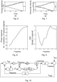
- step a) a frequency of an oscillating reactive torque injected into the electric motor 11 is swept. This is illustrated in Fig. 4 , which shows a frequency sweep of the reactive torque from about 28 Hz to about 36 Hz.
- Reactive torque is to be understood as a torque that oscillates around a value, which may be zero or offset from zero.
- the swept range is selected to cover the expected natural frequency of the motor system 9.
- the reactive torque injected in step a) preferably has a constant amplitude.
- the vibration-related parameter may according to one exemplary embodiment be vibrational velocity of the motor system 1.
- Fig. 5 shows the absolute value, or magnitude, of the reactive vibrational velocity for the frequencies swept in step a).
- the reactive vibrational velocity may for example be detected as acceleration by the sensors 7, which is converted to vibrational speed by the signal conditioner.
- the reactive vibrational velocity v reactive is the velocity of the vibrations of the motor assembly generated as a result of the injected reactive torque ⁇ reactive * .
- step a If the rotor is at a standstill during step a), i.e., at zero rotational speed, the measurements by the sensors 7 results in v reactive because in this case v ext is zero. This also holds if e.g., displacement is measured by the sensors 7 instead of acceleration.
- the electric motor 3 is at standstill during step a).
- the natural frequency of the motor system 1 is where the reactive vibration-related parameter, in this case vibrational velocity, attains its maximum amplitude, which is at about 32.4 Hz according to the present example.
- step b) the natural frequency of the motor system 1 is determined by identifying the frequency of the reactive torque injected in step a), and thus of the vibration-related parameter, which generates the maximum amplitude.
- Step b) ends the first stage of the method, which was to determine the natural frequency of the motor system 1.
- Step c) starts the second stage of the method, which is to determine the gain and phase response of the motor system 1 at the natural frequency.
- a step c) the magnitude of reactive torque oscillating at the natural frequency, injected to the electric motor 5, is incrementally increased.
- the incremental increase may for example be from a level of 1% of the nominal torque to a level of 10% of the nominal torque, for example in steps of 1 percentage point, i.e., 1%, 2%, 3%,..., 10% of the nominal torque.
- the values of the reactive torque, in % is as an example shown in Fig. 6 , with the data points being indicated by circles.
- a magnitude of the vibration-related parameter is obtained for each magnitude of the reactive torque injected in step c).
- the corresponding data points for the reactive vibrational velocity are shown in Fig. 7 .
- Steps c) and d) may be carried out at standstill of the rotor.
- a gain and a phase response of the motor system 1 is determined.
- Each gain is determined based on the magnitude of the injected reactive torque in step c) and the corresponding magnitude of the vibration-related parameter.
- each gain is determined by a ratio between the magnitude of the vibration-related parameter and the magnitude of the injected reactive torque.
- the absolute value of the total vibrational velocity which is equal to the absolute value of the reactive vibrational velocity at standstill of the rotor, is divided with the absolute value of the reactive torque.
- the gain at 1% of the nominal torque is about 5.75.
- Each phase response is determined based on a phase angle of the injected reactive torque and a phase angle of the corresponding vibration-related parameter.
- each phase response is determined by a difference between the phase angle of the vibration-related parameter and the phase angle of the injected reactive torque.
- the vibration-related parameter oscillates and thus has a phase angle, while the phase angle of the injected reactive torque is known by the control system 5.
- the vibration-related parameter is vibrational velocity
- the vibrational velocity varies over time as the motor assembly vibrates between its two extreme positions, as can be understood from the schematic illustration in Fig. 7 .
- the phase response for the reactive torque injected at 1% of the nominal torque is according to the example about 160°.
- the determined gains and phase responses can be used in a control scheme to control injected reactive torque and thereby reduce vibrations in the electric motor 3. This will be described with reference to Fig. 10 , which shows an exemplary control scheme for vibration reduction of the motor system 1.
- a reactive torque reference ⁇ reactive * in the form of a compensation torque signal is fed to an approximate model 15 of the electric motor 3 driven by the control system 5.
- the approximate model 15 models the gain and phase response of the motor system 1 as determined by the method described above.
- the approximate model is composed of multiple non-linear dynamical systems, including all relevant properties of mechanical, control, and electromagnetics of the motor system 1.
- an estimated reactive vibrational velocity ⁇ reactive is obtained based on the reactive torque reference ⁇ reactive * .
- the reactive torque reference ⁇ reactive * is also fed to a drive line 27, which represents a power converter, such as a variable frequency line, which controls the electric motor 3, the electric motor 3, and the sensors 7.
- a drive line 27 represents a power converter, such as a variable frequency line, which controls the electric motor 3, the electric motor 3, and the sensors 7.
- the total vibrational velocity v tot is the sum of the reactive vibrational velocity v reactive and the vibrational velocity v ext .
- the total vibrational velocity v tot is obtained based on measurements by the sensors 7.
- the reactive vibrational velocity reference v ⁇ reactive is converted to a preliminary reactive torque reference. The conversion may be obtained by multiplying the reactive vibrational velocity reference v ⁇ reactive with the inverse of the gain.
- the phase of the preliminary reactive torque reference is then corrected by means of a time delay module 25 to obtain a new value of the reactive torque reference ⁇ reactive * .
- the phase of the preliminary reactive torque reference may be determined as follows.
- a phase difference ⁇ between the estimated reactive vibrational velocity ⁇ reactive and the estimation of vibrational velocity v ext due to external excitation is determined by a phase shift calculating module 17.
- a difference between ⁇ and the phase difference ⁇ is then determined to obtain a phase error ⁇ .
- the number ⁇ is the phase reference of the injected reactive torque relative to the total vibrational velocity v tot , resulting in destructive interference.
- the phase error ⁇ is fed to a PI controller 19.
- a phase output ⁇ of the PI controller 19 is converted from phase to a time delay in a phase conversion module 21. This time delay is used by the time delay module 25 to obtain the new value of the reactive torque reference ⁇ reactive * .
Landscapes
- Engineering & Computer Science (AREA)
- Power Engineering (AREA)
- Physics & Mathematics (AREA)
- General Physics & Mathematics (AREA)
- Control Of Electric Motors In General (AREA)
Abstract
A method of identifying parameters of a motor system comprising an electric motor assembly and a control system, for vibration reduction in the electric motor assembly, the method comprising: a) sweeping a frequency of an oscillating reactive torque injected into the electric motor, b) determining a natural frequency of the motor system, the natural frequency being the frequency at which the oscillating reactive torque produces a maximum amplitude of a vibration-related parameter obtained based on vibration-related measurements by sensors mounted to the electric motor, c) incrementally increasing a magnitude of reactive torque oscillating at the natural frequency, injected to the electric motor, d) obtaining a magnitude of the vibration-related parameter for each magnitude of the reactive torque injected in step c), and e) determining, for each magnitude of the injected reactive torque, a gain and a phase response of the motor system, the gain being determined based on the magnitude of the injected reactive torque and the corresponding magnitude of the vibration-related parameter, and the phase response being determined based on a phase angle of the injected reactive torque and a phase angle of the corresponding vibration-related parameter.
Description
- The present disclosure generally relates to electric motors.
- Severe vibrations of the foundation of an electrical motor occur when an electrical motor operates at natural frequencies of the mechanical body, i.e., of the entire motor assembly. Traditionally, this problem has been resolved by making design modifications to the mechanical assembly to alter the natural frequency modes. This involves either design modifications to the machine itself, replacing machine bearings with higher damping factor or modifications of the mounting assembly, etc.
- Another approach with electrical motors fed from a frequency converter is to use frequency skip functions which prohibits the operation of the machine at critical speeds. Still during acceleration and deceleration of motor, there are instances when machine speed passes through the natural frequency and results in large vibrations. Also, the natural frequency of the mechanical body will change over the period due to mechanical wear, tear, and bearing degradation, resulting in different unbalance to the rotating mass. The correct natural frequencies must be measured and accordingly skip frequencies must be modified. This is costly, time consuming and can cause halt in machine operation which may not be feasible in certain applications.
- A better approach is to use a frequency converter to inject a compensation torque reference which is added to the torque reference generated by the frequency converter's speed controller. This additional torque generates counter forces in the air gap of the machine which leads to suppression of machine vibrations. The machine vibrations at critical frequencies are damped in both steady state as well as dynamic operating conditions of the machine. The output of PI-type or PR-type controllers is increased to a value sufficient to suppress mechanical vibrations below acceptable limits. Still, there are always small vibrations presents in the machine structure, which drive the PI-type controller to saturate, leading to dynamic stability issues. Thus, it is still not known what the optimal compensation signal should be. The use of Phase Locked Loop (PLL) in the control system is another source of instability issue while motor speed is undergoing dynamic changes. The delay caused by synchronization of the PLL leads to suboptimal operation of the vibration controller and can even lead to control instability issues.
- Thus, in view of the above an object of the present disclosure is to provide a method which solves or at least mitigates the problems of the prior art.
- There is hence according to a first aspect of the present disclosure provided a method of identifying parameters of a motor system comprising an electric motor assembly and a control system, for vibration reduction in the electric motor assembly, the method comprising: a) sweeping a frequency of an oscillating reactive torque injected into the electric motor, b) determining a natural frequency of the motor system, the natural frequency being the frequency at which the oscillating reactive torque produces a maximum amplitude of a vibration-related parameter obtained based on vibration-related measurements by sensors mounted to the electric motor, c) incrementally increasing a magnitude of reactive torque oscillating at the natural frequency, injected to the electric motor, d) obtaining a magnitude of the vibration-related parameter for each magnitude of the reactive torque injected in step c), and e) determining, for each magnitude of the injected reactive torque, a gain and a phase response of the motor system, the gain being determined based on the magnitude of the injected reactive torque and the corresponding magnitude of the vibration-related parameter, and the phase response being determined based on a phase angle of the injected reactive torque and a phase angle of the corresponding vibration-related parameter.
- By using the parameters determined by the method in an adaptive closedloop control strategy, the gain and the phase of the injected reactive torque can be controlled adaptively during electric motor operation. Without these parameters, the information regarding the external excitation caused by vibrations at the natural frequency is lost when the counteracting vibrations are injected by the reactive torque. An accurate model of the motor system, excluding the external excitation force can be obtained based on the gain and the phase response, and the external excitations may be reconstructed from the total vibrations, i.e., the vibrations generated by external resonance excitation and resonance excited by the reactive torque, using the gain and the phase response. Based on the gain the exact amplitude of the reactive torque to be injected to essentially completely compensate for horizontal vibrations can be obtained. The phase response is used to set the phase angle of the reactive torque, instead of using a PLL.
- Thus, the vibration performance of the electric motor during operation may be improved. Additionally, the operating speed range of the electric motor is increased as it can be operated at the natural frequency of the motor system. Additionally, the lifetime of the bearings of the electric motor is increased, and the structural noise as a result of vibrations is reduced. There is also no need for any mechanical modifications to reduce the vibrations.
- The parameter identification process is in general a two-phase process wherein the natural frequency of vibrations of the motor system is measured in the first phase and the control parameters, gain and phase response, at that natural frequency are identified in the second phase.
- According to one embodiment the oscillating reactive torque is injected at constant amplitude in step a).
- According to one embodiment in step e) each gain is determined by a ratio between the magnitude of the vibration-related parameter and the magnitude of the injected reactive torque.
- According to one embodiment in step e) each phase response is determined by a difference between the phase angle of the vibration-related parameter and the phase angle of the injected reactive torque.
- According to one embodiment the vibration-related parameter is one of vibrational velocity, acceleration, and displacement.
- According to one embodiment the sensors are accelerometers, and the vibration-related parameter is vibrational velocity, and wherein the method comprises converting the acceleration to vibrational velocity.
- According to one embodiment the sensors measure horizontal acceleration.
- One embodiment comprises utilising the natural frequency, the gains, and the phase responses in a control scheme to control injected reactive torque and thereby reduce vibrations in the electric motor. In particular, the injected reactive torque will counteract mechanical vibrations in the electric motor.
- There is according to a second aspect of the present disclosure provided a computer program comprising computer code which when executed by a processing circuitry of a control system causes the control system to perform the steps of the method as claimed in any of the preceding claims.
- There is according to a third aspect of the present disclosure provided a control system comprising: a storage medium comprising computer code, and processing circuitry configured to execute the computer code, causing the control system to perform the method of the first aspect.
- The control system may comprise a variable speed drive (VSD) for main control tasks. The vibration control can be implemented on the VSD or using a separate controller.
- There is according to a fourth aspect of the present disclosure provided a motor system comprising: an electric motor, and the control system of the third aspect, configured to control the electric motor.
- Generally, all terms used in the claims are to be interpreted according to their ordinary meaning in the technical field, unless explicitly defined otherwise herein. All references to "a/an/the element, apparatus, component, means", etc. are to be interpreted openly as referring to at least one instance of the element, apparatus, component, means, etc., unless explicitly stated otherwise.
- The specific embodiments of the inventive concept will now be described, by way of example, with reference to the accompanying drawings, in which:
-
Fig. 1 schematically shows a motor system; -
Fig. 2 schematically shows a block diagram of a control system; -
Fig. 3 is a flowchart of a method of identifying parameters of a motor system; -
Fig. 4 shows an example of a frequency sweep of reactive torque injected to an electric motor; -
Fig. 5 shows the absolute value of reactive vibrational velocity of vibrations of the motor system resulting from the frequency sweep inFig. 4 ; -
Fig. 6 shows injected reactive torque in incremental steps; -
Fig. 7 shows the resultant velocity of the vibration for each incremental step inFig. 6 ; -
Fig. 8 shows the phase response of the motor system for each incremental step inFig. 6 ; -
Fig. 9 shows the gain of the motor system for each incremental step inFig. 6 ; and -
Fig. 10 shows a block diagram of a control scheme for compensating for vibrations in a motor system utilising the parameters obtained by the method ofFig. 3 . - The inventive concept will now be described more fully hereinafter with reference to the accompanying drawings, in which exemplifying embodiments are shown. The inventive concept may, however, be embodied in many different forms and should not be construed as limited to the embodiments set forth herein; rather, these embodiments are provided by way of example so that this disclosure will be thorough and complete, and will fully convey the scope of the inventive concept to those skilled in the art. Like numbers refer to like elements throughout the description.
-
Fig. 1 shows an example of amotor system 1. Themotor system 1 comprises a motor assembly including anelectric motor 3, the foundation on which theelectric motor 3 stands, and the outer cover of theelectric motor 3. Themotor system 1 also comprises acontrol system 5 configured to control theelectric motor 3, and a plurality ofsensors 7. - The
sensors 7 are configured to make vibration-related measurements of a vibration-related parameter such as acceleration, vibrational velocity, displacement, or sound, of themotor system 1. The sensors may thus for example be accelerometers, displacement sensors, or microphones. In case of accelerometers, the sensors may for example be arranged to measure horizontal acceleration, i.e., acceleration in the horizontal plane. -
Fig. 2 schematically depicts a block diagram of an example of thecontrol system 5. Thecontrol system 5 is configured to identify parameters of themotor system 1, and to control theelectric motor 3 based on the parameters to reduce vibrations of the motor assembly. - The
control system 5 comprises aninput unit 9 configured to receive the vibration-related measurements from the sensors. - The
control system 5 comprises processingcircuitry 11 configured to process the vibration-related measurements. - According to one example, the
control system 5 may comprise a signal conditioner which converts the vibration-related measurements from one vibration-related parameter to another. For example, the sensors may be accelerometers, and the signal conditioner may be configured to convert the acceleration to vibrational velocity. The thus obtained vibration-related parameter is then processed by theprocessing circuitry 11. - The
control system 5 may comprise astorage medium 13. Thestorage medium 13 may comprise a computer program including computer code which when executed by theprocessing circuitry 13 causes thecontrol system 5 to perform the methods as disclosed herein. - The
processing circuitry 11 may for example use any combination of one or more of a suitable central processing unit (CPU), multiprocessor, microcontroller, digital signal processor (DSP), application specific integrated circuit (ASIC), field programmable gate arrays (FPGA) etc., capable of executing any herein disclosed operations concerning identification of parameters of themotor system 1. - The
storage medium 13 may for example be embodied as a memory, such as a random access memory (RAM), a read-only memory (ROM), an erasable programmable read-only memory (EPROM), or an electrically erasable programmable read-only memory (EEPROM) and more particularly as a non-volatile storage medium of a device in an external memory such as a USB (Universal Serial Bus) memory or a Flash memory, such as a compact Flash memory. - A method of identifying parameters of the
motor system 1 will now be described with reference toFigs. 3-9 . - The method is generally divided into two stages; a first stage comprising steps a)-b) and a second stage comprising steps c)-e) described in the following.
- In step a) a frequency of an oscillating reactive torque injected into the
electric motor 11 is swept. This is illustrated inFig. 4 , which shows a frequency sweep of the reactive torque from about 28 Hz to about 36 Hz. Reactive torque is to be understood as a torque that oscillates around a value, which may be zero or offset from zero. - The swept range is selected to cover the expected natural frequency of the
motor system 9. - The reactive torque reference

electric motor 11 is based may be expressed as:
- The reactive torque injected in step a) preferably has a constant amplitude.
- The vibration-related parameter may according to one exemplary embodiment be vibrational velocity of the
motor system 1.Fig. 5 shows the absolute value, or magnitude, of the reactive vibrational velocity for the frequencies swept in step a). The reactive vibrational velocity may for example be detected as acceleration by thesensors 7, which is converted to vibrational speed by the signal conditioner. The reactive vibrational velocity vreactive is the velocity of the vibrations of the motor assembly generated as a result of the injected reactive torque
motor system 1 is given by vtot=vreactive+vext, where vext is the vibrational velocity of all vibrations other than vreactive. If the rotor is at a standstill during step a), i.e., at zero rotational speed, the measurements by thesensors 7 results in vreactive because in this case vext is zero. This also holds if e.g., displacement is measured by thesensors 7 instead of acceleration. Hereto, according to one example, theelectric motor 3 is at standstill during step a). - The natural frequency of the
motor system 1 is where the reactive vibration-related parameter, in this case vibrational velocity, attains its maximum amplitude, which is at about 32.4 Hz according to the present example. - In a step b) the natural frequency of the
motor system 1 is determined by identifying the frequency of the reactive torque injected in step a), and thus of the vibration-related parameter, which generates the maximum amplitude. - Step b) ends the first stage of the method, which was to determine the natural frequency of the
motor system 1. Step c) starts the second stage of the method, which is to determine the gain and phase response of themotor system 1 at the natural frequency. - In a step c) the magnitude of reactive torque oscillating at the natural frequency, injected to the
electric motor 5, is incrementally increased. The incremental increase may for example be from a level of 1% of the nominal torque to a level of 10% of the nominal torque, for example in steps of 1 percentage point, i.e., 1%, 2%, 3%,..., 10% of the nominal torque. The values of the reactive torque, in %, is as an example shown inFig. 6 , with the data points being indicated by circles. - In a step d) a magnitude of the vibration-related parameter is obtained for each magnitude of the reactive torque injected in step c). The corresponding data points for the reactive vibrational velocity are shown in
Fig. 7 . - Steps c) and d) may be carried out at standstill of the rotor.
- In a step e) for each magnitude of the injected reactive torque a gain and a phase response of the
motor system 1 is determined. - Each gain is determined based on the magnitude of the injected reactive torque in step c) and the corresponding magnitude of the vibration-related parameter. In particular, each gain is determined by a ratio between the magnitude of the vibration-related parameter and the magnitude of the injected reactive torque. Thus, for example for the reactive torque injected at 1% of the nominal torque, with the vibration-related parameter being vibrational velocity, the absolute value of the total vibrational velocity, which is equal to the absolute value of the reactive vibrational velocity at standstill of the rotor, is divided with the absolute value of the reactive torque. According to the example shown in
Fig. 9 , the gain at 1% of the nominal torque is about 5.75. - Each phase response is determined based on a phase angle of the injected reactive torque and a phase angle of the corresponding vibration-related parameter. In particular, each phase response is determined by a difference between the phase angle of the vibration-related parameter and the phase angle of the injected reactive torque. The vibration-related parameter oscillates and thus has a phase angle, while the phase angle of the injected reactive torque is known by the
control system 5. For example, if the vibration-related parameter is vibrational velocity, the vibrational velocity varies over time as the motor assembly vibrates between its two extreme positions, as can be understood from the schematic illustration inFig. 7 . As shown inFig. 8 , the phase response for the reactive torque injected at 1% of the nominal torque is according to the example about 160°. - The determined gains and phase responses can be used in a control scheme to control injected reactive torque and thereby reduce vibrations in the
electric motor 3. This will be described with reference toFig. 10 , which shows an exemplary control scheme for vibration reduction of themotor system 1. - A reactive torque reference

approximate model 15 of theelectric motor 3 driven by thecontrol system 5. Theapproximate model 15 models the gain and phase response of themotor system 1 as determined by the method described above. The approximate model is composed of multiple non-linear dynamical systems, including all relevant properties of mechanical, control, and electromagnetics of themotor system 1. - By means of the
approximate model 15, an estimated reactive vibrational velocity ṽreactive , is obtained based on the reactive torque reference
- The reactive torque reference

drive line 27, which represents a power converter, such as a variable frequency line, which controls theelectric motor 3, theelectric motor 3, and thesensors 7. This results in the generation of reactive vibrational velocity vreactive in thedrive line 27, and a vibrational velocity vext due to external excitation of thedrive line 27. The total vibrational velocity vtot is the sum of the reactive vibrational velocity vreactive and the vibrational velocity vext. The total vibrational velocity vtot is obtained based on measurements by thesensors 7. - The difference between the estimated reactive vibrational velocity ṽreactive and the total vibrational velocity vtot , is obtained and this difference is an estimation of vibrational velocity ṽext due to external excitation of the
electric motor 3. The estimation of vibrational velocity ṽext due to external excitation of theelectric motor 3, which is a constant, is then inverted by multiplication with -1 for destructive interference. This results in a reactive vibrational velocity reference v ∗ reactive . In an inversegain multiplier module 23, the reactive vibrational velocity reference v ∗ reactive is converted to a preliminary reactive torque reference. The conversion may be obtained by multiplying the reactive vibrational velocity reference v ∗ reactive with the inverse of the gain. The phase of the preliminary reactive torque reference is then corrected by means of atime delay module 25 to obtain a new value of the reactive torque reference
- The phase of the preliminary reactive torque reference may be determined as follows. A phase difference δ between the estimated reactive vibrational velocity ṽreactive and the estimation of vibrational velocity vext due to external excitation is determined by a phase
shift calculating module 17. According to the example, a difference between π and the phase difference δ, is then determined to obtain a phase error ε. The number π is the phase reference of the injected reactive torque relative to the total vibrational velocity vtot , resulting in destructive interference. The phase error ε is fed to aPI controller 19. A phase output θ of thePI controller 19 is converted from phase to a time delay in aphase conversion module 21. This time delay is used by thetime delay module 25 to obtain the new value of the reactive torque reference
- The inventive concept has mainly been described above with reference to a few examples. However, as is readily appreciated by a person skilled in the art, other embodiments than the ones disclosed above are equally possible within the scope of the inventive concept, as defined by the appended claims.
Claims (11)
- A method of identifying parameters of a motor system (1) comprising an electric motor assembly, and a control system (5), for vibration reduction in the electric motor assembly, the method comprising:a) sweeping a frequency of an oscillating reactive torque injected into the electric motor (3),b) determining a natural frequency of the motor system (1), the natural frequency being the frequency at which the oscillating reactive torque produces a maximum amplitude of a vibration-related parameter obtained based on vibration-related measurements by sensors (7) mounted to the electrical motor (3),c) incrementally increasing a magnitude of reactive torque oscillating at the natural frequency, injected to the electric motor (3),d) obtaining a magnitude of the vibration-related parameter for each magnitude of the reactive torque injected in step c), ande) determining, for each magnitude of the injected reactive torque, a gain and a phase response of the motor system (1), the gain being determined based on the magnitude of the injected reactive torque and the corresponding magnitude of the vibration-related parameter, and the phase response being determined based on a phase angle of the injected reactive torque and a phase angle of the corresponding vibration-related parameter.
- The method as claimed in claim 1, wherein the oscillating reactive torque is injected at constant amplitude in step a).
- The method as claimed in any of the preceding claims, wherein in step e) each gain is determined by a ratio between the magnitude of the vibration-related parameter and the magnitude of the injected reactive torque.
- The method as claimed in any of the preceding claims, wherein in step e) each phase response is determined by a difference between the phase angle of the vibration-related parameter and the phase angle of the injected reactive torque.
- The method as claimed in any of the preceding claims, wherein the - vibration-related parameter is one of vibrational velocity, acceleration, and displacement.
- The method as claimed in claim 5, wherein the sensors (7) are accelerometers, and the vibration-related parameter is vibrational velocity, and wherein the method comprises converting the acceleration to vibrational velocity.
- The method as claimed in any of the preceding claims, wherein the sensors measure horizontal acceleration.
- Method as claimed in any of the preceding claims, comprising utilising the natural frequency, the gains, and the phase responses in a control scheme to control injected reactive torque and thereby reduce vibrations in the electric motor assembly.
- Computer program comprising computer code which when executed by a processing circuitry (11) of a control system (5) causes the control system (5) to perform the steps of the method as claimed in any of the preceding claims.
- A control system (5) comprising:a storage medium (13) comprising computer code, andprocessing circuitry (11) configured to execute the computer code, causing the control system (5) to perform the method as claimed in any of claims 1-8.
- A motor system (1) comprising:an electric motor assembly including an electric motor (3), andthe control system (5) as claimed in claim 10, configured to control the electric motor (3).
Priority Applications (2)
| Application Number | Priority Date | Filing Date | Title |
|---|---|---|---|
| EP23164935.1A EP4439968A1 (en) | 2023-03-29 | 2023-03-29 | Method of identifying parameters of a motor system |
| US18/604,667 US20240333187A1 (en) | 2023-03-29 | 2024-03-14 | Method of identifying parameters of a motor system |
Applications Claiming Priority (1)
| Application Number | Priority Date | Filing Date | Title |
|---|---|---|---|
| EP23164935.1A EP4439968A1 (en) | 2023-03-29 | 2023-03-29 | Method of identifying parameters of a motor system |
Publications (1)
| Publication Number | Publication Date |
|---|---|
| EP4439968A1 true EP4439968A1 (en) | 2024-10-02 |
Family
ID=85781873
Family Applications (1)
| Application Number | Title | Priority Date | Filing Date |
|---|---|---|---|
| EP23164935.1A Pending EP4439968A1 (en) | 2023-03-29 | 2023-03-29 | Method of identifying parameters of a motor system |
Country Status (2)
| Country | Link |
|---|---|
| US (1) | US20240333187A1 (en) |
| EP (1) | EP4439968A1 (en) |
Citations (2)
| Publication number | Priority date | Publication date | Assignee | Title |
|---|---|---|---|---|
| JP5316424B2 (en) * | 2007-12-27 | 2013-10-16 | 株式会社安川電機 | Motor control device |
| US20230025973A1 (en) * | 2021-07-15 | 2023-01-26 | Abb Schweiz Ag | Method and an Arrangement for Controlling Vibration of a Variable Frequency Drive Controlled Electric Machine |
-
2023
- 2023-03-29 EP EP23164935.1A patent/EP4439968A1/en active Pending
-
2024
- 2024-03-14 US US18/604,667 patent/US20240333187A1/en active Pending
Patent Citations (2)
| Publication number | Priority date | Publication date | Assignee | Title |
|---|---|---|---|---|
| JP5316424B2 (en) * | 2007-12-27 | 2013-10-16 | 株式会社安川電機 | Motor control device |
| US20230025973A1 (en) * | 2021-07-15 | 2023-01-26 | Abb Schweiz Ag | Method and an Arrangement for Controlling Vibration of a Variable Frequency Drive Controlled Electric Machine |
Also Published As
| Publication number | Publication date |
|---|---|
| US20240333187A1 (en) | 2024-10-03 |
Similar Documents
| Publication | Publication Date | Title |
|---|---|---|
| JP5571365B2 (en) | Torsional mode damping device | |
| US8890454B2 (en) | Phase locked loop based torsional mode damping system and method | |
| JP4685509B2 (en) | AC motor drive control device and drive control method | |
| EP3454469B1 (en) | Torque ripple reduction for a generator and wind turbine including the same | |
| US9729094B2 (en) | Automatic suppression device for cyclic disturbance | |
| US20160218650A1 (en) | Method and system for damping torsional oscillations | |
| AU2011234461B9 (en) | Rectifier based torsional mode damping system and method | |
| EP2073375A1 (en) | Apparatus for avoiding torque components at critical frequencies in machine drive systems | |
| US20130106330A1 (en) | Rectifier and inverter based torsional mode damping system and method | |
| US9054629B2 (en) | Sensorless torsional mode damping system and method | |
| EP4439968A1 (en) | Method of identifying parameters of a motor system | |
| EP4439969A1 (en) | Method of reducing mechanical vibrations of a motor system | |
| EP2651028B1 (en) | Estimation of cogging torque | |
| ul Haq et al. | Optimal damping of horizontal mode resonance of an electric drive train using reactive torque | |
| EP4472059A1 (en) | Method of reducing vibrations in an electric motor | |
| WO2022179926A1 (en) | Controlling a wind turbine with respect to dynamic stability |
Legal Events
| Date | Code | Title | Description |
|---|---|---|---|
| PUAI | Public reference made under article 153(3) epc to a published international application that has entered the european phase |
Free format text: ORIGINAL CODE: 0009012 |
|
| STAA | Information on the status of an ep patent application or granted ep patent |
Free format text: STATUS: THE APPLICATION HAS BEEN PUBLISHED |
|
| AK | Designated contracting states |
Kind code of ref document: A1 Designated state(s): AL AT BE BG CH CY CZ DE DK EE ES FI FR GB GR HR HU IE IS IT LI LT LU LV MC ME MK MT NL NO PL PT RO RS SE SI SK SM TR |
|
| STAA | Information on the status of an ep patent application or granted ep patent |
Free format text: STATUS: REQUEST FOR EXAMINATION WAS MADE |
|
| 17P | Request for examination filed |
Effective date: 20250402 |