EP4439956A1 - Apparatus for power conversion and method for operating the apparatus - Google Patents
Apparatus for power conversion and method for operating the apparatus Download PDFInfo
- Publication number
- EP4439956A1 EP4439956A1 EP23168562.9A EP23168562A EP4439956A1 EP 4439956 A1 EP4439956 A1 EP 4439956A1 EP 23168562 A EP23168562 A EP 23168562A EP 4439956 A1 EP4439956 A1 EP 4439956A1
- Authority
- EP
- European Patent Office
- Prior art keywords
- ppc
- series
- protector
- converter
- string
- Prior art date
- Legal status (The legal status is an assumption and is not a legal conclusion. Google has not performed a legal analysis and makes no representation as to the accuracy of the status listed.)
- Pending
Links
Images




Classifications
-
- H—ELECTRICITY
- H02—GENERATION; CONVERSION OR DISTRIBUTION OF ELECTRIC POWER
- H02M—APPARATUS FOR CONVERSION BETWEEN AC AND AC, BETWEEN AC AND DC, OR BETWEEN DC AND DC, AND FOR USE WITH MAINS OR SIMILAR POWER SUPPLY SYSTEMS; CONVERSION OF DC OR AC INPUT POWER INTO SURGE OUTPUT POWER; CONTROL OR REGULATION THEREOF
- H02M1/00—Details of apparatus for conversion
- H02M1/32—Means for protecting converters other than automatic disconnection
-
- H—ELECTRICITY
- H02—GENERATION; CONVERSION OR DISTRIBUTION OF ELECTRIC POWER
- H02M—APPARATUS FOR CONVERSION BETWEEN AC AND AC, BETWEEN AC AND DC, OR BETWEEN DC AND DC, AND FOR USE WITH MAINS OR SIMILAR POWER SUPPLY SYSTEMS; CONVERSION OF DC OR AC INPUT POWER INTO SURGE OUTPUT POWER; CONTROL OR REGULATION THEREOF
- H02M1/00—Details of apparatus for conversion
- H02M1/32—Means for protecting converters other than automatic disconnection
- H02M1/325—Means for protecting converters other than automatic disconnection with means for allowing continuous operation despite a fault, i.e. fault tolerant converters
-
- H—ELECTRICITY
- H02—GENERATION; CONVERSION OR DISTRIBUTION OF ELECTRIC POWER
- H02H—EMERGENCY PROTECTIVE CIRCUIT ARRANGEMENTS
- H02H7/00—Emergency protective circuit arrangements specially adapted for specific types of electric machines or apparatus or for sectionalised protection of cable or line systems, and effecting automatic switching in the event of an undesired change from normal working conditions
- H02H7/10—Emergency protective circuit arrangements specially adapted for specific types of electric machines or apparatus or for sectionalised protection of cable or line systems, and effecting automatic switching in the event of an undesired change from normal working conditions for converters; for rectifiers
- H02H7/12—Emergency protective circuit arrangements specially adapted for specific types of electric machines or apparatus or for sectionalised protection of cable or line systems, and effecting automatic switching in the event of an undesired change from normal working conditions for converters; for rectifiers for static converters or rectifiers
- H02H7/1203—Circuits independent of the type of conversion
- H02H7/1206—Circuits independent of the type of conversion specially adapted to conversion cells composed of a plurality of parallel or serial connected elements
-
- H—ELECTRICITY
- H02—GENERATION; CONVERSION OR DISTRIBUTION OF ELECTRIC POWER
- H02J—ELECTRIC POWER NETWORKS; CIRCUIT ARRANGEMENTS OR SYSTEMS FOR SUPPLYING OR DISTRIBUTING ELECTRIC POWER; SYSTEMS FOR STORING ELECTRIC ENERGY
- H02J3/00—Circuit arrangements for AC mains or AC distribution networks
- H02J3/28—Arrangements for balancing of the load in networks by storage of energy
- H02J3/32—Arrangements for balancing of the load in networks by storage of energy using batteries or super capacitors with converting means
-
- H—ELECTRICITY
- H02—GENERATION; CONVERSION OR DISTRIBUTION OF ELECTRIC POWER
- H02J—ELECTRIC POWER NETWORKS; CIRCUIT ARRANGEMENTS OR SYSTEMS FOR SUPPLYING OR DISTRIBUTING ELECTRIC POWER; SYSTEMS FOR STORING ELECTRIC ENERGY
- H02J3/00—Circuit arrangements for AC mains or AC distribution networks
- H02J3/38—Arrangements for feeding a single network from two or more generators or sources in parallel; Arrangements for feeding already energised networks from additional generators or sources in parallel
- H02J3/381—Dispersed generators
-
- H—ELECTRICITY
- H02—GENERATION; CONVERSION OR DISTRIBUTION OF ELECTRIC POWER
- H02J—ELECTRIC POWER NETWORKS; CIRCUIT ARRANGEMENTS OR SYSTEMS FOR SUPPLYING OR DISTRIBUTING ELECTRIC POWER; SYSTEMS FOR STORING ELECTRIC ENERGY
- H02J3/00—Circuit arrangements for AC mains or AC distribution networks
- H02J3/38—Arrangements for feeding a single network from two or more generators or sources in parallel; Arrangements for feeding already energised networks from additional generators or sources in parallel
- H02J3/46—Controlling the sharing of generated power between the generators, sources or networks
-
- H—ELECTRICITY
- H02—GENERATION; CONVERSION OR DISTRIBUTION OF ELECTRIC POWER
- H02M—APPARATUS FOR CONVERSION BETWEEN AC AND AC, BETWEEN AC AND DC, OR BETWEEN DC AND DC, AND FOR USE WITH MAINS OR SIMILAR POWER SUPPLY SYSTEMS; CONVERSION OF DC OR AC INPUT POWER INTO SURGE OUTPUT POWER; CONTROL OR REGULATION THEREOF
- H02M1/00—Details of apparatus for conversion
- H02M1/0067—Converter structures employing plural converter units, other than for parallel operation of the units on a single load
- H02M1/007—Plural converter units in cascade
-
- H—ELECTRICITY
- H02—GENERATION; CONVERSION OR DISTRIBUTION OF ELECTRIC POWER
- H02M—APPARATUS FOR CONVERSION BETWEEN AC AND AC, BETWEEN AC AND DC, OR BETWEEN DC AND DC, AND FOR USE WITH MAINS OR SIMILAR POWER SUPPLY SYSTEMS; CONVERSION OF DC OR AC INPUT POWER INTO SURGE OUTPUT POWER; CONTROL OR REGULATION THEREOF
- H02M1/00—Details of apparatus for conversion
- H02M1/0067—Converter structures employing plural converter units, other than for parallel operation of the units on a single load
- H02M1/0077—Plural converter units whose outputs are connected in series
-
- H—ELECTRICITY
- H02—GENERATION; CONVERSION OR DISTRIBUTION OF ELECTRIC POWER
- H02M—APPARATUS FOR CONVERSION BETWEEN AC AND AC, BETWEEN AC AND DC, OR BETWEEN DC AND DC, AND FOR USE WITH MAINS OR SIMILAR POWER SUPPLY SYSTEMS; CONVERSION OF DC OR AC INPUT POWER INTO SURGE OUTPUT POWER; CONTROL OR REGULATION THEREOF
- H02M1/00—Details of apparatus for conversion
- H02M1/0083—Converters characterised by their input or output configuration
- H02M1/0093—Converters characterised by their input or output configuration wherein the output is created by adding a regulated voltage to or subtracting it from an unregulated input
-
- H—ELECTRICITY
- H02—GENERATION; CONVERSION OR DISTRIBUTION OF ELECTRIC POWER
- H02M—APPARATUS FOR CONVERSION BETWEEN AC AND AC, BETWEEN AC AND DC, OR BETWEEN DC AND DC, AND FOR USE WITH MAINS OR SIMILAR POWER SUPPLY SYSTEMS; CONVERSION OF DC OR AC INPUT POWER INTO SURGE OUTPUT POWER; CONTROL OR REGULATION THEREOF
- H02M3/00—Conversion of DC power input into DC power output
- H02M3/02—Conversion of DC power input into DC power output without intermediate conversion into AC
- H02M3/04—Conversion of DC power input into DC power output without intermediate conversion into AC by static converters
- H02M3/10—Conversion of DC power input into DC power output without intermediate conversion into AC by static converters using discharge tubes with control electrode or semiconductor devices with control electrode
- H02M3/145—Conversion of DC power input into DC power output without intermediate conversion into AC by static converters using discharge tubes with control electrode or semiconductor devices with control electrode using devices of a triode or transistor type requiring continuous application of a control signal
- H02M3/155—Conversion of DC power input into DC power output without intermediate conversion into AC by static converters using discharge tubes with control electrode or semiconductor devices with control electrode using devices of a triode or transistor type requiring continuous application of a control signal using semiconductor devices only
- H02M3/156—Conversion of DC power input into DC power output without intermediate conversion into AC by static converters using discharge tubes with control electrode or semiconductor devices with control electrode using devices of a triode or transistor type requiring continuous application of a control signal using semiconductor devices only with automatic control of output voltage or current, e.g. switching regulators
- H02M3/158—Conversion of DC power input into DC power output without intermediate conversion into AC by static converters using discharge tubes with control electrode or semiconductor devices with control electrode using devices of a triode or transistor type requiring continuous application of a control signal using semiconductor devices only with automatic control of output voltage or current, e.g. switching regulators including plural semiconductor devices as final control devices for a single load
Definitions
- the present disclosure relates to the field of power conversion, and more specifically, to an apparatus and a system for power conversion, and a method for operating an apparatus for power conversion.
- Energy Storage System is a system that contains, for example, batteries (such as, lithium batteries, lead batteries) as energy storage carriers to store electrical energy and supply electrical energy for a certain period of time.
- the ESS is widely used in power grids to adjust the peak and frequency of the power grids, thereby ensuring the safe operation of the power grids. Therefore, it is expected to provide protection for the fault occurs in the ESS to improve the reliability of the ESS.
- the present disclosure provides an apparatus and a system for power conversion and a method for operating the apparatus.
- an apparatus for power conversion includes at least one of a first partial power converter (PPC) string and a second PPC string, wherein the first PPC string comprising more than one series-connected PPCs, wherein an output of each PPC of the more than one series-connected PPCs is connected in series; and wherein the second PPC string comprising at least one series-connected PPC and at least one PPC set, wherein each PPC set comprises more than one parallel-connected PPCs, the respective outputs of the more than one parallel-connected PPCs are connected in parallel and further connected to the output of the PPC set, and respective outputs of the at least one series-connected PPC and the at least one PPC set are connected in series, wherein, for each PPC in the apparatus, the respective input of the PPC is connected to a corresponding power source, and the input of the PPC and the output of the PPC have one common terminal, and the PPC comprises at least one controllable switch, and wherein the at least one of
- the circuit protector comprises the one PPC protector corresponding to each PPC in the apparatus, which corresponds to a series-connected PPC and comprises: a bypass switch connected in parallel with the output of the PPC; and at least one group of series-connected switches, comprising at least one of: a first group of switches connecting in series with the input of the PPC; and a second group of switches connecting in series with the output of the PPC.
- the apparatus comprises the second PPC string
- the circuit protector comprises the one PPC protector corresponding to each PPC in the apparatus and the one set protector corresponding to each PPC set in the apparatus
- the PPC protector corresponds to a parallel-connected PPC and comprises: a first group of switches connecting in series with the input of the PPC; and/or a second group of switches connecting in series with the output of the PPC
- the set protector comprises: a bypass switch connecting in parallel with the output of the PPC set.
- the set protector further comprises: a group of series-connected switches connecting in series with the output of the PPC set.
- the PPC in the apparatus includes a first AC/DC converter and a second AC/DC converter coupled at AC ports of the first AC/DC converter and the second AC/DC converter, and wherein a DC port of the second AC/DC converter forms one of the input and the output of the PPC, and a DC port of the first AC/DC converter and the DC port of the second AC/DC converter are connected in series to form the other of the input and the output of the PPC, and wherein the circuit protector comprises the one PPC protector corresponding to each PPC in the apparatus, which corresponds to a series-connected PPC, and wherein, in response to that the DC port of the second AC/DC converter forms the input of the PPC and the DC port of the first AC/DC converter and the DC port of the second AC/DC converter are connected in series to form the output of the PPC, and the PPC protector comprises a bypass switch connected in parallel with the input of the PPC, and wherein, in response to that the DC port of the second AC/DC converter forms the output of the P
- the circuit protector comprises the one PPC protector corresponding to each PPC in the apparatus, which corresponds to a series-connected PPC and comprises: a bypass switch connected in parallel with the output of the PPC.
- a method of operating the apparatus of power conversion includes: in response to that a fault occurs in the apparatus, operating the circuit protector.
- the set protector comprises: a bypass switch connecting in parallel with the output of the PPC set, and wherein the operating the circuit protector further comprises: in response to that the PPC set corresponding to the fault does not comprise any normal PPC and the number of normal series-connected PPCs and PPC sets in the string corresponding to the fault is larger than a preset threshold, switching on the bypass switch in the set protector for the set corresponding to the fault.
- the PPC in the apparatus includes a first AC/DC converter and a second AC/DC converter coupled at AC ports of the first AC/DC converter and the second AC/DC converter, and wherein a DC port of the second AC/DC converter forms the input of the PPC, and a DC port of the first AC/DC converter and the DC port of the second AC/DC converter are connected in series to form the output of the PPC, and wherein the method further comprises: in response to that the fault occurs at a series-connected PPC and the number of normal series-connected PPCs and PPC sets in the string corresponding to the fault is larger than a preset threshold, switching on all the controllable switches in the PPC corresponding to the fault.
- the PPC in the apparatus includes a first AC/DC converter and a second AC/DC converter coupled at AC ports of the first AC/DC converter and the second AC/DC converter, and wherein a DC port of the second AC/DC converter forms the input of the PPC, and a DC port of the first AC/DC converter and the DC port of the second AC/DC converter are connected in series to form the output of the PPC, and wherein the circuit protector comprises the one PPC protector corresponding to each PPC in the apparatus, which corresponds to a series-connected PPC and comprises: a bypass switch connected in parallel with the input of the PPC, wherein the operating the circuit protector comprises: in response to that the fault occurs at a series-connected PPC and the number of normal series-connected PPCs and PPC sets in the string corresponding to the fault is larger than a preset threshold, switching on all the controllable switches in the first AC/DC converter in the PPC corresponding to the fault, and switching off all the controllable switches in the second AC/DC converter in the
- the PPC in the apparatus includes a first AC/DC converter and a second AC/DC converter coupled at AC ports of the first AC/DC converter and the second AC/DC converter, and wherein a DC port of the second AC/DC converter forms the output of the PPC, and a DC port of the first AC/DC converter and the DC port of the second AC/DC converter are connected in series to form the input of the PPC, and wherein the circuit protector comprises the one PPC protector corresponding to each PPC in the apparatus, which corresponds to a series-connected PPC and comprises: a group of series-connected switches connecting in series with the input of the PPC, wherein the operating the circuit protector comprises: in response to that the fault occurs at a series-connected PPC, switching on all the controllable switches in the second AC/DC converter in the PPC corresponding to the fault, and switching off all the controllable switches in the first AC/DC converter in the PPC corresponding to the fault; and switching off the group of series-connected switches in the PPC protector for the PPC
- the circuit protector comprises the one string protector corresponding to each of the first PPC string and the second PPC string, which comprises: a string switch connected in series with the output of the series-connected PPCs in the string corresponding to the string protector, and wherein the operating the circuit protector comprises: in response to that the fault is a short-circuited fault at the DC bus, switching off all the string switches in the apparatus; and in response to that the fault is a short-circuited fault at a power source, turning off all the controllable switches in the PPC corresponding to the fault, or switching off the string switch in the string protector for the string corresponding to the fault.
- an apparatus for power conversion and a method for operating the apparatus are provided.
- the apparatus for power conversion includes: at least one of a first partial power converters (PPC) string and a second PPC string, wherein the first PPC string comprising more than one series-connected PPCs, wherein an output of each PPC of the more than one series-connected PPCs is connected in series ; and wherein the second PPC string comprising at least one series-connected PPC and at least one PPC set, wherein each PPC set comprises more than one parallel-connected PPCs, the respective outputs of the more than one parallel-connected PPCs are connected in parallel and further connected to the output of the PPC set, and respective outputs of the at least one series-connected PPC and the at least one PPC set are connected in series, wherein, for each PPC in the apparatus, the respective input of the PPC is connected to a corresponding power source, and the input of the PPC and the output of the PPC have one common terminal, and the PPC comprises at least one controllable switch, and wherein the at least one of the first PPC string
- the apparatus of power conversion can provide at least the following advantages:
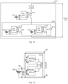
- Figs. 1A-1C are schematic diagrams illustrating an apparatus of power conversion 1000 according to an embodiment of the present disclosure.
- the apparatus of power conversion 1000 includes at least one of a first PPC string 1010 and a second PPC string 1020, wherein the at least one of a first PPC string 1010 and a second PPC string 1020 is connected in parallel with a DC bus 1100.
- the apparatus of power conversion 1000 includes both the first PPC string 1010 and the second PPC string 1020, but the apparatus of power conversion 1000 may include only one of the first PPC string 1010 and the second PPC string 1020.
- the structure of the first PPC string 1010 and the second PPC string 1020 is illustrated below with reference to Figs. 1B-1C respectively.
- the first PPC string 1010 includes more than one series-connected PPCs 1011 a , ... , 101i a , wherein the outputs of the PPCs 1011 a , ..., 101i a in the string 1010 are connected in series, and an input of each PPC of the PPCs 1011 a , ..., 101i a is connected to a corresponding power source, for example, the input of the PPC 1011 a is connected to the corresponding power source 1011 b , and the input of the PPC 10j1 a is connected to the corresponding power source 10j1 b .
- the second string includes at least one series-connected PPC 1021 and at least one PPC set 1022, wherein each PPC set includes more than one parallel-connected PPCs, for example, the PPC set 1022 includes PPC 1023 a , ..., 102j a that are connected in parallel.
- a respective output of each PPC of the more than one parallel-connected PPCs is connected in parallel to form the output of the PPC set.
- the output of PPC 1023 a , ..., 102j a are connected in parallel to form the output of the PPC set 1022.
- a respective output of each of the at least one series-connected PPC 1021 and the at least one PPC set 1022 is connected in series.
- the input of the PPC is connected to a corresponding power source, for example, the series-connected PPC 1021 a is connected to the corresponding power source 1021 b , and the parallel-connected PPC 1023 a in the PPC set 1022 is connected to the corresponding power source 1023 b .
- a respective output of each of the at least one series-connected PPC and the at least one PPC set is connected in series means that, for each PPC or PPC set, one output terminal of the PPC or PPC set is connected to an output terminal of an adjacent PPC or PPC set closer to a first terminal of the DC bus, and the other output terminal of the PPC or PPC set is connected to an output terminal of another adjacent PPC or PPC set closer to a second terminal of the DC bus.
- the input of the PPC and the output of the PPC have one common terminal.
- the PPC in the apparatus comprises at least one controllable switch, wherein the controllable switch is able to be controlled (for example, according to a turn-on/ turn-off signal) and may include IGBT, IGCT, MOSFET, GTO, a triode and the like.
- the partial power converter in present disclosure refers to a converter having partial power processing characteristic, i.e., a fraction of the power goes directly from the source to the load bypassing the converter and the remaining power is processed by the converter, so that the overall efficiency can be improved and the capital cost can be decreased compared with the full power converter.
- the apparatus 1000 further includes a circuit protector, including at least one of one PPC protector corresponding to each PPC in the apparatus; one set protector corresponding to each PPC set in the apparatus; and one string protector corresponding to each of the first PPC string and the second PPC string.
- the first PPC string 1100 there are a string protector 1031 corresponding to the first PPC string 1100 and PPC protectors 1011 c , ..., 101i c corresponding to PPCs 1011 a , ..., 101i a , wherein the PPC protector 1011 c corresponds to the PPC 1011 a , ..., the PPC protector 101i c corresponds to the PPC 101i a .
- a string protector 1032 corresponding to the second PPC string 1200, a set protector 1012 a corresponding to the PPC set 1022 and PPC protectors 1021 c , 1023 c , ..., 102j c corresponding to PPCs 1021 a , 1023 a , ... , 102j a , wherein the PPC protectors 1021 a corresponds to 1021 c , the PPC protectors 1023 a corresponds to 1023 c , ..., the PPC protectors 102j a corresponds to 102j c .
- the setting of the circuit protector in Figs. 1B-1C is only for illustration and the setting of the circuit protector can be different.
- the string protector, the set protector or the PPC protector in Figs. 1B-1C can be omitted.
- the position of the PPC protector can be different from that shown in Figs. 1B-1C , for example, there can be PPC protector connected in series with the input and/or output of the PPC.
- the exemplary implementation of the circuit protector will be further discussed with reference to Figs. 3 , 4 and 5A-5B .
- the apparatus 1000 may also include other string of PPCs, such as another string of series-connected PPCs or series-parallel-connected PPCs, or a string of one PPC.
- other string of PPCs such as another string of series-connected PPCs or series-parallel-connected PPCs, or a string of one PPC.
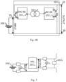
- Figs. 2A-2B are schematic diagrams illustrating the connection configuration of the PPC in Fig. 1A-1C (such as the PPC 1011 a , ..., 101i a in Fig. 1B and the PPC 1021 a , ..., 102j a in Fig. 1C ) according to an embodiment of the present disclosure.
- the PPC in Fig. 1A-1C such as the PPC 1011 a , ..., 101i a in Fig. 1B and the PPC 1021 a , ..., 102j a in Fig. 1C .
- the PPC 1011 a includes a first AC/DC converter 1011 a -1 and a second AC/DC converter 1011 a -2.
- the term "AC/DC converter” is not intended to limit the conversion directions of AC and DC of the converter.
- the AC/DC converter may convert DC to AC or convert AC to DC.
- any of first AC/DC converter 1011 a -1 and a second AC/DC converter 1011 a -2 may have the following circuit structure: H bridge, IGBT, IGCT, MOSFET, GTO or a single diode, and the like.
- the first AC/DC converter 1011 a -1 and the second AC/DC converter 1011 a -2 coupled at AC ports of the first AC/DC converter 1011 a -1 and the second AC/DC converter 1011 a -2, and the DC port of the second AC/DC converter forms one of the input and the output of the PPC 1011 a .
- a DC port of the first AC/DC converter 1011 a -1 and the DC port of the second AC/DC converter 1011 a -2 are connected in series to form the other of the input and the output of the PPC 1011 a .
- the DC port of the second AC/DC converter 1011 a -2 are connected in series to form the other of the input and the output of the PPC 1011 means that, for each AC/DC converter, one DC terminal of the DC port is connected to the DC terminal of the DC port of the other AC/DC converter, and the other terminal of the DC port is connected to the terminal of the PPC (i.e., the terminal of the input or output of the PPC).
- an AC side of the first AC/DC converter 1011 a -1 and an AC side of the second AC/DC converter 1011 a -2 are electromagnetically coupled or coupled through a capacitor.
- the "electromagnetically coupled” may refer to being coupled through a transformer 1011 a -3 or inductor.
- a DC port of the first AC/DC converter 1011 a -1 and the DC port of the second AC/DC converter 1011 a -2 are connected in series to form the output of the PPC 1011 a .
- a DC port of the first AC/DC converter 1011 a -1 and the DC port of the second AC/DC converter 1011 a -2 are connected in series to form the output of the PPC 1011 a .
- a DC side of the first AC/DC converter 1011 a -1 has a first DC terminal 1 and a second DC terminal 2
- a DC side of the second AC/DC converter 1011 a -2 has a third DC terminal 3 and a fourth DC terminal 4, wherein the first DC terminal 1 is connected to the first terminal 10 of the PPC 1011 a , the second DC terminal 2 and the third DC terminal 3 are connected to the second terminal 20 of the PPC 1011 a , and the fourth DC terminal 4 is connected to the third terminal 30 of the PPC 1011 a .
- a part of the power goes directly from the power source 1011 b to the output of the PPC 1011 a by bypassing the first AC/DC converter 1011 a -1 and the second AC/DC converter 1011 a -2 and the remaining power is processed by the first AC/DC converter 1011 a -1 and the second AC/DC converter 1011 a -2 and then delivered to the output of the PPC 1011 a .
- a DC port of the first AC/DC converter 1011 a - 1 and the DC port of the second AC/DC converter 1011 a -2 are connected in series to form the input of the PPC 1011 a .
- a DC side of the first AC/DC converter 1011 a -1 has a first DC terminal 1 and a second DC terminal 2
- a DC side of the second AC/DC converter 1011 a -2 has a third DC terminal 3 and a fourth DC terminal 4, wherein the first DC terminal 1 is connected to the second terminal 20 of the PPC 1011 a , the second DC terminal 2 and the third DC terminal 3 are connected to the first terminal 10 of the PPC 1011 a , and the fourth DC terminal 4 is connected to the third terminal 30 of the PPC 1011 a .
- a part of the power goes directly from the power source 1011 b to the output of the PPC 1011 a by bypassing the first AC/DC converter 1011 a -1 and the second AC/DC converter 1011 a -2 and the remaining power is processed by the first AC/DC converter 1011 a -1 and the second AC/DC converter 1011 a -2 and then delivered to the output of the PPC 1011 a .
- At least one switching device in each of the first AC/DC converter 1011 a -1 and the second AC/DC converter 1011 a -2 is a controllable switch.
- the controllable switch may include IGBT, IGCT, MOSFET, GTO, a triode and the like.
- a rated power of each of the first AC/DC converter 1011 a -1 and the second AC/DC converter 1011 a -2 may be less than a rated power of the respective power source 101 1 b , thereby further reducing the cost of the converter and increasing the power efficiency.
- the circuit protector comprises the one PPC protector corresponding to each PPC in the apparatus, which corresponds to a series-connected PPC and comprises: a bypass switch connected in parallel with the output of the PPC; and at least one group of series-connected switches, comprising at least one of: a first group of switches connecting in series with the input of the PPC; and a second group of switches connecting in series with the output of the PPC.
- Fig. 3 is a schematic diagram illustrating the PPC protector corresponding to the series-connected PPC in the apparatus of power conversion 1000 in Figs. 1A-1C (such as the PPC 1011 a , ..., 101i a in Fig. 1B and the PPC 1021 a in Fig. 1C ) according to an embodiment of the present disclosure.
- the PPC protector for the PPC 1011 a includes a bypass switch 1011 c connected in parallel with the output of the PPC 1011 a and at least one of a first group of switches 1011 d and a second group of switches 1011 e , wherein the first group of switches 1011 d is connected in series with the input of the PPC 1011 a , and the second group of switches 1011 e is connected in series with the output of the PPC 1011 a .
- the first group of switches 1011 d and/or the second group of switches 1011 e can be used to cut off the power of the PPC 1011 a and can be disconnectors or other types of workable switches.
- the bypass switch 1011 c can be used to bypass the PPC 1011 a and can be a breaker or other types of a workable switch.
- the apparatus comprises the second PPC string
- the circuit protector comprises the one PPC protector corresponding to each PPC in the apparatus and the one set protector corresponding to each PPC set in the apparatus
- the PPC protector corresponds to a parallel-connected PPC and comprises: a first group of switches connecting in series with the input of the PPC; and/or a second group of switches connecting in series with the output of the PPC
- the set protector comprises: a bypass switch connecting in parallel with the output of the PPC set.
- the set protector further comprises: a group of series-connected switches connecting in series with the output of the PPC set.
- the switch connected in series with the input and/or output of the PPC by setting the switch connected in series with the input and/or output of the PPC, the power from the input and/or output of the PPC can be cut off when a fault occurs at the parallel-connected PPC within the PPC set, thus achieving the effect of fault removal; and, by setting the bypass switch for the PPC set, the PPC set can be bypassed when the parallel-connected PPCs within the PPC set are cut off due to fault, so that other normal PPC and/or PPC set in the same string can continue operation and the reliability of the apparatus is improved.
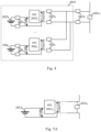
- Fig. 4 is a schematic diagram illustrating the PPC protector corresponding to the parallel-connected PPC (such as PPC 1023 a , ..., PPC 102j a in Fig. 1C ) and the set protector corresponding to the PPC set (such as PPC set 1022 in Fig. 1C ) in the apparatus of power conversion 1000 in Figs. 1A-1C according to an embodiment of the present disclosure.
- the corresponding PPC protector includes a first group of switches connecting in series with the input of the PPC; and/or a second group of switches connecting in series with the output of the PPC.
- the PPC protector corresponding to the PPC 1023 a includes a first group of switches 1023 c connecting in series with the input of the PPC 1023 a and/or a second group of switches 1023 d connecting in series with the output of the PPC 1023 a .
- the first group of switches and/or the second group of switches of the PPC protector can be used to cut off the power of the PPC and can be disconnectors or other types of workable switches.
- the corresponding set protector includes a bypass switch connecting in parallel with the output of the PPC set 1022 a .
- the bypass switch 1022 a can be used to bypass the parallel-connected PPCs 1023 a , ... , 102j a in the PPC set 1022 and can be a breaker or other types of a workable switch.
- the set protector for the PPC set 1022 may further includes a group of series-connected switches 1022 b connecting in series with the output of the PPC set 1022, which can be used to cut off the power from the parallel-connected PPCs 1023 a , ... , 102j a in the PPC set 1022 for safety and can also be omitted for conciseness.
- the group of series-connected switches 1022 b can be disconnectors or other types of workable switches.
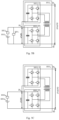
- Figs. 5A-5D are schematic diagrams illustrating the PPC protector corresponding to the series-connected PPC in the apparatus of power conversion 1000 in Figs. 1A-1C (such as the PPC 1011 a , ..., 101i a in Fig. 1B and the PPC 1021 a in Fig. 1C ) according to an embodiment of the present disclosure.
- the circuit protector comprises the one PPC protector corresponding to each PPC in the apparatus, which corresponds to a series-connected PPC and comprises: a bypass switch connected in parallel with the output of the PPC.
- a bypass switch connected in parallel with the output of the PPC.
- the PPC protector includes a bypass switch 1011 c connected in parallel with the output of the PPC 1011 a .
- the bypass switch 1011 c can be used to bypass the PPC 1011 a and can be a breaker or other types of a workable switch.
- the PPC in the apparatus includes a first AC/DC converter and a second AC/DC converter coupled at AC ports of the first AC/DC converter and the second AC/DC converter, and wherein a DC port of the second AC/DC converter forms the input of the PPC, and a DC port of the first AC/DC converter and the DC port of the second AC/DC converter are connected in series to form the output of the PPC, and wherein the circuit protector comprises the one PPC protector corresponding to each PPC in the apparatus, which corresponds to a series-connected PPC and comprises: a bypass switch connected in parallel with the input of the PPC.
- the bypass switch and the first AC/DC in the PPC can bypass the PPC corresponding to the fault, so that other normal PPC and/or PPC set in the same string can continue operation and the reliability of the apparatus is improved.
- the controllable switch in the first AC/DC converter in PPC usually has low voltage and high current characteristics, while the controllable switch in the second AC/DC converter in PPC usually has low current and high voltage characteristics.
- the first AC/DC converter with the high current characteristic is used to bypass the high current of other normally series-connected PPC and/or PPC set in the same string, while the second AC/DC converter with the low current characteristic is bypassed by the bypass switch to avoid undertaking the high current of other normally series-connected PPC and/or PPC set in the same string, making full use of the controllable switches in the PPC according to their characteristics.
- the PPC protector includes a bypass switch 1011 c connected in parallel with the output of the PPC 1011 a .
- the bypass switch 1011 c can be used to bypass the second AC/DC converter 1011 a -2 in the PPC 1011 a and can be a breaker or other types of a workable switch.
- the first AC/DC converter 1011 a -1 can be used in combination with the bypass switch 1011 c to bypass the power source 1011 b , for example, the controllable switches in the first AC/DC converter 1011 a -1 (for example, a H bridge circuit) are held closed to bypass the current.
- the PPC protector also includes a source protection device 1011 d connected in series with the corresponding power source 1011 b , which can be fuse or load switch or contactor to cut off the connection between the power source 101 1 b and the PPC 1011 a when the fault occurs in the corresponding power source 1011 b .
- a source protection device 1011 d connected in series with the corresponding power source 1011 b , which can be fuse or load switch or contactor to cut off the connection between the power source 101 1 b and the PPC 1011 a when the fault occurs in the corresponding power source 1011 b .
- the bypass switch connected in parallel with the input of the PPC can be omitted, and both the first AC/DC converter and the second AC/DC converter in the PPC are used to bypass the corresponding power source.
- the controllable switches in the first AC/DC converter and the second AC/DC converter are held closed to bypass the current, so that other normal PPC and/or PPC set in the same string can continue operation, and the reliability of the apparatus is improved.
- the PPC protector only includes a source protection device 1011 d connected in series with the corresponding power source 1011 b , which can be fuse or load switch or contactor to cut off the connection between the power source 1011 b and the PPC 1011 a when the fault occurs in the corresponding power source 1011 b .
- the PPC in the apparatus includes a first AC/DC converter and a second AC/DC converter coupled at AC ports of the first AC/DC converter and the second AC/DC converter, and wherein a DC port of the second AC/DC converter forms the output of the PPC, and a DC port of the first AC/DC converter and the DC port of the second AC/DC converter are connected in series to form the input of the PPC, and wherein the circuit protector comprises the one PPC protector corresponding to each PPC in the apparatus, which corresponds to a series-connected PPC and comprises: a group of series-connected switches connecting in series with the input of the PPC.
- the PPC protector when the fault occurs at the series-connected PPC, the PPC corresponding to the fault can be bypassed by the second AC/DC converter in the PPC, so that other normal PPC and/or PPC set in the same string can continue operation, and the reliability of the apparatus is improved; accordingly, only the components of the second AC/DC converter in the PPC (for example, the controllable switch), and not all the components in the PPC need to be designed with a capacity large enough to bypass current, thus saving the cost of device expansion.
- the PPC protector includes a group of series-connected switches 1011 c connecting in series with the input of the PPC 1011 a .
- the series-connected switches of the PPC protector may be used to cut off the electrical connection between the power source and the PPC, and be disconnectors or other types of workable switches.
- the second AC/DC converter 1011 a -2 may be used in conjunction with the series-connected switches 1011 c to bypass PPC 1011 b when the fault occurs at the corresponding power source 1011 b .
- the controllable switch of the second AC/DC converter 1011 a -2 e.g.
- H-bridge circuit is kept closed to bypass the current that would otherwise pass through PPC 1011 a , while the series-connected switches 1011c are switched off to cut off the electrical connection from PPC 1011 a (especially the output side of PPC 1011 a ) to the power source 1011 b .
- the circuit protector comprises the one string protector corresponding to each of the first PPC string and the second PPC string, which comprises: a string switch connected in series with the output of the series-connected PPCs in the string corresponding to the string protector.
- the string switch can be set to cut off the corresponding string in the event of the relative serious intra-string fault (e.g., a short circuit fault at the power supply) so as not to affect the normal operation of other strings in the apparatus, or all strings in the apparatus may be cut off in the event of the fault at the bus (e.g., a short circuit fault) to protect all components of the apparatus from the influence of the bus fault.
- Fig. 6 is a schematic diagram illustrating the string protector for the string of PPCs in the apparatus of power conversion 1000 in Figs. 1A-1C (such as the strings 1010 and 1020 in Figs. 1A-1C ) according to an embodiment of the present disclosure.
- the string protector corresponding to the string 1010 includes a string switch 1031 connected in series with the PPCs 1011 a , ..., 101i a .
- the string switch can be a bidirectional breaker or other types of workable switch.
- the string switch includes two controllable switches connected in series, as shown in Fig. 6 .
- a method of operating the apparatus of power conversion including: in response to that a fault occurs in the apparatus, operating the circuit protector.
- the fault in the apparatus can be cleared by corresponding operation of the circuit protector, so as to improve the reliability of the apparatus.
- Fig. 7 is a flowchart showing a method 700 for controlling an apparatus for power conversion 1000 in Figs. 1A-1C according to an embodiment of the present disclosure, in which the apparatus for power conversion is substantially the same as described with reference to Figs. 1A-1C , and thus the details as to the same features are omitted here for conciseness.
- the method 700 includes the step S701.
- step S701 in response to that a fault occurs in the apparatus, the circuit protector is operated.
- step S701 The details of step S701 is described below.
- the corresponding PPC protector, the set protector and/or the string protector operates according to the position and the type of the fault occurred in the apparatus.
- the circuit protector comprises the one PPC protector corresponding to each PPC in the apparatus, which corresponds to a series-connected PPC and comprises: a bypass switch connected in parallel with the output of the PPC; and at least one group of series-connected switches, comprising at least one of: a first group of switches connecting in series with the input of the PPC; and a second group of switches connecting in series with the output of the PPC, and wherein the operating the circuit protector comprises: in response to that the fault occurs at a series-connected PPC, switching off all the controllable switches in the PPC corresponding to the fault; switching off the at least one group of series-connected switches in the PPC protector for the PPC corresponding to the fault; and in response to that the number of normal series-connected PPCs and PPC sets in the string corresponding to the fault is larger than a preset threshold, switching on the bypass switch in the PPC protector for the PPC corresponding to the fault.
- Fig. 8 is a flowchart illustrating the process S701 of operating the circuit protector in Fig. 7 according to an embodiment of the present disclosure.
- the process S701 shown in Fig. 8 can be performed through the PPC 1011 a and the PPC protector in Fig. 3 .
- the process 701 includes: In step S801, in response to that the fault occurs at a series-connected PPC, all the controllable switches in the PPC corresponding to the fault are switched off.
- the fault occurs at a series-connected PPC means that the fault occurs in the series-connected PPC or the corresponding power source connected to the PPC.
- the thermal runaway may happen during the charging/discharging operation of battery cells due to extreme working conditions or battery defect, and the controller of the PPC may receive the information of abnormal operation of the battery from BMS or an additional sensor (e.g. temperature sensor or gas sensor) when the temperature of the battery exceeds the threshold value.
- BMS e.g. temperature sensor or gas sensor
- all controllable switches in the PPC are turned off through stopping the PWM signals of the controllable switches in the PPC.
- the PWM signals of controllable switches in the PPC 1011 a are stopped.
- step S802 the at least one group of series-connected switches in the PPC protector for the PPC corresponding to the fault is switched off.
- the first group of series-connected switches 1011 d can be switched off to cut off the power from the input of the PPC 1011 a
- the second group of series-connected switches 1011 e can be switched off to cut off the power from the output of the PPC 1011 a .
- step S803 in response to that the number of normal series-connected PPCs and PPC sets in the string corresponding to the fault is larger than a preset threshold, the bypass switch in the PPC protector for the PPC corresponding to the fault is switched on.
- bypass switch 1011 c can be switched on to bypass the PPC 1011 a .
- the operation of the normal series-connected PPCs and PPC sets in the string can be resumed to recover the operation of the string, wherein the normal series-connected PPCs and PPC sets in the string are connected in parallel with the DC bus.
- the apparatus of power conversion when the apparatus of power conversion is controlling the DC bus voltage, the voltage references of the normal series-connected PPCs and PPC sets in the same string are increased, so that the loss of the PPC corresponding to the fault can be compensated and the normal series-connected PPCs and PPC sets in the same string can still operate.
- the normal series-connected PPCs and PPC sets in the string in response to that the number of normal series-connected PPCs and PPC sets in the string corresponding to the fault is less than or equal to a preset threshold, can not withstand the DC bus voltage, e.g., the normal series-connected PPCs and PPC sets in the string can not build the DC bus voltage, and the bypass switch in the PPC protector for the PPC remains switched off.
- the apparatus comprises the second PPC string
- the circuit protector comprises the one PPC protector corresponding to each PPC in the apparatus and the one set protector corresponding to each PPC set in the apparatus
- the PPC protector corresponds to a parallel-connected PPC and comprises: a first group of switches connecting in series with the input of the PPC; and/or a second group of switches connecting in series with the output of the PPC
- the operating the circuit protector comprises: in response to that the fault occurs at a parallel-connected PPC, switching off all the controllable switches in the PPC corresponding to the fault; and switching off the at least one group of series-connected switches in the PPC protector for the PPC corresponding to the fault.
- the set protector comprises: a bypass switch connecting in parallel with the output of the PPC set, and wherein the operating the circuit protector further comprises: in response to that the PPC set corresponding to the fault does not comprise any normal PPC and the number of normal series-connected PPCs and PPC sets in the string corresponding to the fault is larger than a preset threshold, switching on the bypass switch in the set protector for the set corresponding to the fault.
- the PPC set can be bypassed when all parallel-connected PPCs within the PPC set are cut off due to fault, so that other normal PPC and/or PPC set in the same string can continue operation and the reliability of the apparatus is improved.
- Fig. 9 is a flowchart illustrating the process S701 of operating the circuit protector in Fig. 7 according to an embodiment of the present disclosure.
- the process S701 shown in Fig. 9 can be performed through the PPC 1023 a , ... , 102j a and the PPC protector in Fig. 4 .
- the process 701 includes: In step S901, in response to that the fault occurs at a parallel-connected PPC, all the controllable switches in the PPC corresponding to the fault are switched off.
- Step S901 can be implemented similar to Step S801 in Fig. 8 , and the description therefore is omitted for conciseness.
- the PWM signals of controllable switches in the PPC 1023 a are stopped.
- step S902 the at least one group of series-connected switches in the PPC protector for the PPC corresponding to the fault is switched off.
- Step S902 can be implemented similar to Step S802 in Fig. 8 , and the description therefore is omitted for conciseness.
- the first group of series-connected switches 1023 d can be switched off to cut off the power from the input of the PPC 1023 a
- the second group of series-connected switches 1011 e can be switched off to cut off the power from the output of the PPC 1023 a .
- step S903 in response to that the PPC set corresponding to the fault does not comprise any normal PPC and the number of normal series-connected PPCs and PPC sets in the string corresponding to the fault is larger than a preset threshold, the bypass switch in the set protector for the set corresponding to the fault is switched on.
- the bypass switch 1022 a corresponding to the set of PPCs 1022 is switched on.
- the normal PPCs in the PPC set can still operate.
- the apparatus of power conversion when the apparatus of power conversion is controlling the DC bus voltage, after all the PPCs in the set of PPCs are cut off due to fault, the voltage references of the normal series-connected PPCs and PPC sets in the same string are increased, so that the loss of the PPC corresponding to the fault can be compensated and the normal series-connected PPCs and PPC sets in the same string can still operate.
- Step S803 in response to that the number of normal series-connected PPCs and PPC sets in the string corresponding to the fault is less than or equal to a preset threshold, the normal series-connected PPCs and PPC sets in the string cannot withstand the DC bus voltage, e.g., the normal series-connected PPCs and PPC sets in the string cannot build the DC bus voltage, and the bypass switch in the PPC protector for the PPC remains switched off.
- the PPC in the apparatus includes a first AC/DC converter and a second AC/DC converter coupled at AC ports of the first AC/DC converter and the second AC/DC converter, and wherein a DC port of the second AC/DC converter forms the input of the PPC, and a DC port of the first AC/DC converter and the DC port of the second AC/DC converter are connected in series to form the output of the PPC, and wherein the method further comprises: in response to that the fault occurs at a series-connected PPC and the number of normal series-connected PPCs and PPC sets in the string corresponding to the fault is larger than a preset threshold, switching on all the controllable switches in the PPC corresponding to the fault.
- the PPC corresponding to the fault can be bypassed when the fault occurs at the series-connected PPC, so that other normal PPC and/or PPC set in the same string can continue operation and the reliability of the apparatus is improved.
- the state of the source protection device 1011 d changes, which can be detected to trigger the fault protection operation, such as the switching on all controllable switches in the PPC as mentioned above.
- the source protection device 1011 d is a fuse
- the fuse is broken when the fault occurs, which can be detected by the BMS and further sent to the controller of the PPC to send the turning-on signals to all controllable switches in the PPC.
- the circuit protector comprises the one PPC protector corresponding to each PPC in the apparatus, which corresponds to a series-connected PPC and comprises: a bypass switch connected in parallel with the output of the PPC, and wherein the operating the circuit protector comprises: in response to that the fault occurs at a series-connected PPC, switching off all the controllable switches in the PPC corresponding to the fault; and in response to that the number of normal series-connected PPCs and PPC sets in the string corresponding to the fault is larger than a preset threshold, switching on the bypass switch in the PPC protector for the PPC corresponding to the fault.
- the PPC corresponding to the fault can be bypassed when the fault occurs at the series-connected PPC, so that other normal PPC and/or PPC set in the same string can continue operation and the reliability of the apparatus is improved.
- Fig. 10 is a flowchart illustrating the process S701 of operating the circuit protector in Fig. 7 according to an embodiment of the present disclosure.
- the process S701 shown in Fig. 10 can be performed through the PPC 1011 a and the PPC protector in Fig. 5A .
- the process 701 includes: In step S1001, in response to that the fault occurs at a series-connected PPC, all the controllable switches in the PPC corresponding to the fault are switched off.
- Step S1001 can be implemented similar to Step S801 in Fig. 8 , and the description therefore is omitted for conciseness.
- the PWM signals of controllable switches in the PPC 1011 a are stopped.
- step S 1002 in response to that the number of normal series-connected PPCs and PPC sets in the string corresponding to the fault is larger than a preset threshold, the bypass switch in the PPC protector for the PPC corresponding to the fault is switched on.
- Step S1002 can be implemented similar to Step S803 in Fig. 8 , and the description therefore is omitted for conciseness.
- the bypass switch 1011 c can be switched on to bypass the PPC 1011 a , so that the current goes through the bypass switch 1011 c , and other normal series-connected PPC and/or PPC set in the same string can still continue their operation.
- the PPC in the apparatus includes a first AC/DC converter and a second AC/DC converter coupled at AC ports of the first AC/DC converter and the second AC/DC converter, and wherein a DC port of the second AC/DC converter forms the input of the PPC, and a DC port of the first AC/DC converter and the DC port of the second AC/DC converter are connected in series to form the output of the PPC, and wherein the circuit protector comprises the one PPC protector corresponding to each PPC in the apparatus, which corresponds to a series-connected PPC and comprises: a bypass switch connected in parallel with the input of the PPC, wherein the operating the circuit protector comprises: in response to that the fault occurs at a series-connected PPC and the number of normal series-connected PPCs and PPC sets in the string corresponding to the fault is larger than a preset threshold, switching on all the controllable switches in the first AC/DC converter in the PPC corresponding to the fault, and switching off all the controllable switches in the second AC/DC converter in the
- the controllable switch in the first AC/DC converter in PPC can be designed to have the low voltage and high current characteristics, while the controllable switch in the second AC/DC converter in PPC can be designed to the have low current and high voltage characteristics, the first AC/DC converter with the high current characteristic is used to bypass the high current of other normally series-connected PPC and/or PPC set in the same string, while the second AC/DC converter with the low current characteristic is bypassed by the bypass switch to avoid undertaking the high current of other normally series-connected PPC and/or PPC set in the same
- Fig. 11 is a flowchart illustrating the process S701 of operating the circuit protector in Fig. 7 according to an embodiment of the present disclosure. According to some embodiments, the process S701 shown in Fig. 11 can be performed through the PPC 1011 a and the PPC protector in Fig. 5B . As shown in Fig.
- the process 701 includes: In step S1101, in response to that the fault occurs at a series-connected PPC and the number of normal series-connected PPCs and PPC sets in the string corresponding to the fault is larger than a preset threshold, all the controllable switches in the first AC/DC converter in the PPC corresponding to the fault are switched on, and all the controllable switches in the second AC/DC converter in the PPC corresponding to the fault are switched off.
- all controllable switches in the first AC/DC converter are held closed, for example, the controllable switches in the PPC keep receiving the turning-on signals, and all controllable switches in the second AC/DC converter are held open, for example, the controllable switches in the PPC keep receiving the turning-off signals.
- the state of the source protection device 1011 d changes, which can be detected to trigger the fault protection operation, such as the switching on all the controllable switches in the first AC/DC converter in the PPC corresponding to the fault and switching off all the controllable switches in the second AC/DC converter in the PPC corresponding to the fault as mentioned above.
- step S1102 the bypass switch in the PPC protector for the PPC corresponding to the fault is switched on.
- the bypass switch 1011 c connected in parallel with the input of the second AC/DC converter 1011 a -2, so that the current goes through the first AC/DC converter 1011 a -1 and the first bypass switch 1011 c , and other normal series-connected PPC and/or PPC set in the same string can still continue their operation.
- the PPC corresponding to the fault can be bypassed when the fault occurs at the series-connected PPC, so that other normal PPC and/or PPC set in the same string can continue operation, and the reliability of the apparatus is improved; accordingly, only the components of the second AC/DC converter in the PPC (for example, the controllable switch), and not all the components in the PPC need to be designed with a capacity large enough to bypass current, thus saving the cost of device expansion.
- all controllable switches in the first AC/DC converter are held open, for example, the controllable switches in the PPC keep receiving the turning-off signals, and all controllable switches in the second AC/DC converter are held closed, for example, the controllable switches in the PPC keep receiving the turning-on signals.
- step S1202 the group of series-connected switches in the PPC protector for the PPC corresponding to the fault is switched off.
- the series-connected switches 1011 c is switched off to cut off the electrical connection from PPC 1011 a (especially the output side of the PPC 1011 a ) to the power source 1011 b .
- the circuit protector comprises the one string protector corresponding to each of the first PPC string and the second PPC string, which comprises: a string switch connected in series with the output of the series-connected PPCs in the string corresponding to the string protector, and wherein the operating the circuit protector comprises: in response to that the fault is a short-circuited fault at the DC bus, switching off all the string switches in the apparatus; and in response to that the fault is a short-circuited fault at a power source, turning off all the controllable switches in the PPC corresponding to the fault, or switching off the string switch in the string protector for the string corresponding to the fault.
- the string switch 1031 when a short-circuited fault occurs at the DC bus, the string switch 1031 is switched off (for example, the controllable switches in the string switch 1031 are switched off), so that the string current can be stopped from increasing quickly; when a short-circuited fault occurs at a power source (for example, the power source 1011 b ), all the controllable switches in the PPC corresponding to the fault (for example, the PPC 1011 a corresponding to the power source 1011 a ) are switched off, or the string switch 1031 is switched off, so that the current is prevented from flowing from the bus to the power source to stop the current from increasing quickly due to the short-circuit fault.
- a power source for example, the power source 1011 b
- all the controllable switches in the PPC corresponding to the fault for example, the PPC 1011 a corresponding to the power source 1011 a
- a system for power conversion which includes: the above apparatus of power conversion (e.g., the apparatus 1000 in Figs. 1A-1C ); a DC bus (e.g., the DC bus 1200 in Figs. 1A-1C ); and a plurality of power sources connected to the apparatus (e.g., the power sources 1011 b , ..., 101i b ,..., 1021 b ,...,102k b in Figs. 1A-1C ).
- each block in the flowchart or block diagram may represent a module, program segment, or part of code, and the module, program segment, or part of code contains one or more executable instructions for implementing the logical functions.
- the functions marked in the blocks may also occur in an order different from that marked in the accompanying drawings. For example, two blocks shown in succession can actually be performed substantially in parallel, or they can sometimes be performed in the reverse order, depending on the functions involved.
- each block in the block diagram and/or the flowchart, and a combination of the blocks in the block diagram and/or the flowchart may be implemented by a dedicated hardware-based system that executes functions or operations, or may be implemented by a combination of dedicated hardware and computer instructions.
Landscapes
- Engineering & Computer Science (AREA)
- Power Engineering (AREA)
- Rectifiers (AREA)
Abstract
An apparatus for power conversion and a method for operating the apparatus are provided. The apparatus comprises: at least one of a first partial power converters (PPC) string and a second PPC string, wherein the first PPC string comprising more than one series-connected PPCs, wherein an output of each PPC of the more than one series-connected PPCs is connected in series; and wherein the second PPC string comprising at least one series-connected PPC and at least one PPC set, wherein each PPC set comprises more than one parallel-connected PPCs, the respective outputs of the more than one parallel-connected PPCs are connected in parallel and further connected to the output of the PPC set, and respective outputs of the at least one series-connected PPC and the at least one PPC set are connected in series, wherein, for each PPC in the apparatus, the respective input of the PPC is connected to a corresponding power source, and the input of the PPC and the output of the PPC have one common terminal, and the PPC comprises at least one controllable switch, and wherein the at least one of the first PPC string and the second PPC string is connected in parallel with a DC bus , and a circuit protector, comprising at least one of: one PPC protector corresponding to each PPC in the apparatus; one set protector corresponding to each PPC set in the apparatus; and one string protector corresponding to each of the first PPC string and the second PPC string.

Description
- The present disclosure relates to the field of power conversion, and more specifically, to an apparatus and a system for power conversion, and a method for operating an apparatus for power conversion.
- Energy Storage System (ESS) is a system that contains, for example, batteries (such as, lithium batteries, lead batteries) as energy storage carriers to store electrical energy and supply electrical energy for a certain period of time. The ESS is widely used in power grids to adjust the peak and frequency of the power grids, thereby ensuring the safe operation of the power grids. Therefore, it is expected to provide protection for the fault occurs in the ESS to improve the reliability of the ESS.
- The present disclosure provides an apparatus and a system for power conversion and a method for operating the apparatus.
- According to an aspect of the present disclosure, an apparatus for power conversion is provided. The apparatus includes at least one of a first partial power converter (PPC) string and a second PPC string, wherein the first PPC string comprising more than one series-connected PPCs, wherein an output of each PPC of the more than one series-connected PPCs is connected in series; and wherein the second PPC string comprising at least one series-connected PPC and at least one PPC set, wherein each PPC set comprises more than one parallel-connected PPCs, the respective outputs of the more than one parallel-connected PPCs are connected in parallel and further connected to the output of the PPC set, and respective outputs of the at least one series-connected PPC and the at least one PPC set are connected in series, wherein, for each PPC in the apparatus, the respective input of the PPC is connected to a corresponding power source, and the input of the PPC and the output of the PPC have one common terminal, and the PPC comprises at least one controllable switch, and wherein the at least one of the first PPC string and the second PPC string is connected in parallel with a DC bus, and a circuit protector, comprising at least one of: one PPC protector corresponding to each PPC in the apparatus; one set protector corresponding to each PPC set in the apparatus; and one string protector corresponding to each of the first PPC string and the second PPC string.
- According to some embodiments, the circuit protector comprises the one PPC protector corresponding to each PPC in the apparatus, which corresponds to a series-connected PPC and comprises: a bypass switch connected in parallel with the output of the PPC; and at least one group of series-connected switches, comprising at least one of: a first group of switches connecting in series with the input of the PPC; and a second group of switches connecting in series with the output of the PPC.
- According to some embodiments, the apparatus comprises the second PPC string, and the circuit protector comprises the one PPC protector corresponding to each PPC in the apparatus and the one set protector corresponding to each PPC set in the apparatus, and wherein the PPC protector corresponds to a parallel-connected PPC and comprises: a first group of switches connecting in series with the input of the PPC; and/or a second group of switches connecting in series with the output of the PPC, and wherein the set protector comprises: a bypass switch connecting in parallel with the output of the PPC set.
- According to some embodiments, the set protector further comprises: a group of series-connected switches connecting in series with the output of the PPC set.
- According to some embodiments, the PPC in the apparatus includes a first AC/DC converter and a second AC/DC converter coupled at AC ports of the first AC/DC converter and the second AC/DC converter, and wherein a DC port of the second AC/DC converter forms one of the input and the output of the PPC, and a DC port of the first AC/DC converter and the DC port of the second AC/DC converter are connected in series to form the other of the input and the output of the PPC, and wherein the circuit protector comprises the one PPC protector corresponding to each PPC in the apparatus, which corresponds to a series-connected PPC, and wherein, in response to that the DC port of the second AC/DC converter forms the input of the PPC and the DC port of the first AC/DC converter and the DC port of the second AC/DC converter are connected in series to form the output of the PPC, and the PPC protector comprises a bypass switch connected in parallel with the input of the PPC, and wherein, in response to that the DC port of the second AC/DC converter forms the output of the PPC and the DC port of the first AC/DC converter and the DC port of the second AC/DC converter are connected in series to form the input of the PPC, and the PPC protector comprises a group of series-connected switches connecting in series with the input of the PPC.
- According to some embodiments, the circuit protector comprises the one PPC protector corresponding to each PPC in the apparatus, which corresponds to a series-connected PPC and comprises: a bypass switch connected in parallel with the output of the PPC.
- According to some embodiments, circuit protector comprises the one string protector corresponding to each of the first PPC string and the second PPC string, which comprises: a string switch connected in series with the output of the series-connected PPCs in the string corresponding to the string protector.
- According to an aspect of the present disclosure, a method of operating the apparatus of power conversion according to the present disclosure. The method includes: in response to that a fault occurs in the apparatus, operating the circuit protector.
- According to some embodiments, the circuit protector comprises the one PPC protector corresponding to each PPC in the apparatus, which corresponds to a series-connected PPC and comprises: a bypass switch connected in parallel with the output of the PPC; and at least one group of series-connected switches, comprising at least one of: a first group of switches connecting in series with the input of the PPC; and a second group of switches connecting in series with the output of the PPC, and wherein the operating the circuit protector comprises: in response to that the fault occurs at a series-connected PPC, switching off all the controllable switches in the PPC corresponding to the fault; switching off the at least one group of series-connected switches in the PPC protector for the PPC corresponding to the fault; and in response to that the number of normal series-connected PPCs and PPC sets in the string corresponding to the fault is larger than a preset threshold, switching on the bypass switch in the PPC protector for the PPC corresponding to the fault.
- According to some embodiments, the apparatus comprises the second PPC string, and the circuit protector comprises the one PPC protector corresponding to each PPC in the apparatus and the one set protector corresponding to each PPC set in the apparatus, and wherein the PPC protector corresponds to a parallel-connected PPC and comprises: a first group of switches connecting in series with the input of the PPC; and/or a second group of switches connecting in series with the output of the PPC, and wherein the operating the circuit protector comprises: in response to that the fault occurs at a parallel-connected PPC, switching off all the controllable switches in the PPC corresponding to the fault; and switching off the at least one group of series-connected switches in the PPC protector for the PPC corresponding to the fault.
- According to some embodiments, the set protector comprises: a bypass switch connecting in parallel with the output of the PPC set, and wherein the operating the circuit protector further comprises: in response to that the PPC set corresponding to the fault does not comprise any normal PPC and the number of normal series-connected PPCs and PPC sets in the string corresponding to the fault is larger than a preset threshold, switching on the bypass switch in the set protector for the set corresponding to the fault.
- According to some embodiments, the PPC in the apparatus includes a first AC/DC converter and a second AC/DC converter coupled at AC ports of the first AC/DC converter and the second AC/DC converter, and wherein a DC port of the second AC/DC converter forms the input of the PPC, and a DC port of the first AC/DC converter and the DC port of the second AC/DC converter are connected in series to form the output of the PPC, and wherein the method further comprises: in response to that the fault occurs at a series-connected PPC and the number of normal series-connected PPCs and PPC sets in the string corresponding to the fault is larger than a preset threshold, switching on all the controllable switches in the PPC corresponding to the fault.
- According to some embodiments, the circuit protector comprises the one PPC protector corresponding to each PPC in the apparatus, which corresponds to a series-connected PPC and comprises: a bypass switch connected in parallel with the output of the PPC, and wherein the operating the circuit protector comprises: in response to that the fault occurs at a series-connected PPC, switching off all the controllable switches in the PPC corresponding to the fault; and in response to that the number of normal series-connected PPCs and PPC sets in the string corresponding to the fault is larger than a preset threshold, switching on the bypass switch in the PPC protector for the PPC corresponding to the fault.
- According to some embodiments, the PPC in the apparatus includes a first AC/DC converter and a second AC/DC converter coupled at AC ports of the first AC/DC converter and the second AC/DC converter, and wherein a DC port of the second AC/DC converter forms the input of the PPC, and a DC port of the first AC/DC converter and the DC port of the second AC/DC converter are connected in series to form the output of the PPC, and wherein the circuit protector comprises the one PPC protector corresponding to each PPC in the apparatus, which corresponds to a series-connected PPC and comprises: a bypass switch connected in parallel with the input of the PPC, wherein the operating the circuit protector comprises: in response to that the fault occurs at a series-connected PPC and the number of normal series-connected PPCs and PPC sets in the string corresponding to the fault is larger than a preset threshold, switching on all the controllable switches in the first AC/DC converter in the PPC corresponding to the fault, and switching off all the controllable switches in the second AC/DC converter in the PPC corresponding to the fault; and switching on the bypass switch in the PPC protector for the PPC corresponding to the fault.
- According to some embodiments, the PPC in the apparatus includes a first AC/DC converter and a second AC/DC converter coupled at AC ports of the first AC/DC converter and the second AC/DC converter, and wherein a DC port of the second AC/DC converter forms the output of the PPC, and a DC port of the first AC/DC converter and the DC port of the second AC/DC converter are connected in series to form the input of the PPC, and wherein the circuit protector comprises the one PPC protector corresponding to each PPC in the apparatus, which corresponds to a series-connected PPC and comprises: a group of series-connected switches connecting in series with the input of the PPC, wherein the operating the circuit protector comprises: in response to that the fault occurs at a series-connected PPC, switching on all the controllable switches in the second AC/DC converter in the PPC corresponding to the fault, and switching off all the controllable switches in the first AC/DC converter in the PPC corresponding to the fault; and switching off the group of series-connected switches in the PPC protector for the PPC corresponding to the fault.
- According to some embodiments, the circuit protector comprises the one string protector corresponding to each of the first PPC string and the second PPC string, which comprises: a string switch connected in series with the output of the series-connected PPCs in the string corresponding to the string protector, and wherein the operating the circuit protector comprises: in response to that the fault is a short-circuited fault at the DC bus, switching off all the string switches in the apparatus; and in response to that the fault is a short-circuited fault at a power source, turning off all the controllable switches in the PPC corresponding to the fault, or switching off the string switch in the string protector for the string corresponding to the fault.
- It should be understood that the content described in this section is not intended to identify critical or important features of the embodiments of the present disclosure, and is not used to limit the scope of the present disclosure either. Other features of the present disclosure will be easily understood through the following specification.
- The drawings exemplarily show embodiments and form a part of the specification, and are used to illustrate example implementations of the embodiments together with a written description of the specification. The embodiments shown are merely for illustrative purposes and do not limit the scope of the claims. Throughout the drawings, like reference signs denote like but not necessarily identical elements.
-
Figs. 1A-1C are schematic diagrams illustrating an apparatus of power conversion according to an embodiment of the present disclosure. -
Figs. 2A-2B are schematic diagrams illustrating the connection configuration of the PPC inFig. 1A-1C according to an embodiment of the present disclosure. -
Fig. 3 is a schematic diagram illustrating the PPC protector for series-connected PPC in the apparatus of power conversion inFigs. 1A-1C according to an embodiment of the present disclosure. -
Fig. 4 is a schematic diagram illustrating the PPC protector for parallel-connected PPC and the set protector in the apparatus of power conversion inFigs. 1A-1C according to an embodiment of the present disclosure. -
Fig. 5A-5D are schematic diagrams illustrating the PPC protector for series-connected PPC in the apparatus of power conversion inFigs. 1A-1C according to an embodiment of the present disclosure. -
Fig. 6 is a schematic diagram illustrating the string protector for the string of PPCs in the apparatus of power conversion inFigs. 1A-1C according to an embodiment of the present disclosure. -
Fig. 7 is a flowchart illustrating a method for operating the apparatus of power conversion inFigs. 1A-1C according to an embodiment of the present disclosure. -
Fig. 8 is a flowchart illustrating the process of operating the circuit protector inFig. 7 according to an embodiment of the present disclosure. -
Fig. 9 is a flowchart illustrating the process of operating the circuit protector inFig. 7 according to an embodiment of the present disclosure. -
Fig. 10 is a flowchart illustrating the process of operating the circuit protector inFig. 7 according to an embodiment of the present disclosure. -
Fig. 11 is a flowchart illustrating the process of operating the circuit protector inFig. 7 according to an embodiment of the present disclosure. -
Fig. 12 is a flowchart illustrating the process of operating the circuit protector inFig. 7 according to an embodiment of the present disclosure. - The present disclosure will be further described in detail below with reference to the drawings and embodiments. It can be understood that embodiments described herein are used merely to explain a related disclosure, rather than limit the disclosure. It should be additionally noted that, for ease of description, only parts related to the related disclosure are shown in the drawings.
- It should be noted that the embodiments in the present disclosure and features in the embodiments can be combined with each other without conflict. If the number of elements is not specifically defined, there may be one or more elements, unless otherwise expressly indicated in the context. In addition, numbers of steps or functional modules used in the present disclosure are used merely to identify the steps or functional modules, rather than limit either a sequence of performing the steps or a connection relationship between the functional modules. As used herein, the term "and/or" includes any and all combinations of one or more of the associated listed items. The term "based on" is to be construed as "based at least in part on".
- According to embodiments of the present disclosure, an apparatus for power conversion and a method for operating the apparatus are provided.
- According to some embodiments, the apparatus for power conversion includes: at least one of a first partial power converters (PPC) string and a second PPC string, wherein the first PPC string comprising more than one series-connected PPCs, wherein an output of each PPC of the more than one series-connected PPCs is connected in series ; and wherein the second PPC string comprising at least one series-connected PPC and at least one PPC set, wherein each PPC set comprises more than one parallel-connected PPCs, the respective outputs of the more than one parallel-connected PPCs are connected in parallel and further connected to the output of the PPC set, and respective outputs of the at least one series-connected PPC and the at least one PPC set are connected in series, wherein, for each PPC in the apparatus, the respective input of the PPC is connected to a corresponding power source, and the input of the PPC and the output of the PPC have one common terminal, and the PPC comprises at least one controllable switch, and wherein the at least one of the first PPC string and the second PPC string is connected in parallel with a DC bus, and a circuit protector, comprising at least one of: one PPC protector corresponding to each PPC in the apparatus; one set protector corresponding to each PPC set in the apparatus; and one string protector corresponding to each of the first PPC string and the second PPC string.
- According to the embodiments of the present disclosure, the apparatus of power conversion can provide at least the following advantages:
- 1) PPCs based on power electronics and the corresponding circuit protector can sense the power source fault and eliminate the fault influence, so that the fault influence can be limited, thereby providing fast fault diagnosis, location and clearance;
- 2) The unbalanced current between the parallel connected strings of power sources (such as the battery cells) can be limited, thereby the lifetime of the power sources can be extended;
- 3) More accurate control for each power source can be provided, thereby making full use of the energy of each power source, even if the multiple power sources in one string are in different status (for example, in different SOC status)
- 4) More than one PPCs can be connected in series to build DC bus with higher voltage level, which makes the connection to the MV system easier (for example, through a grid-connected AC/DC converter);
- 5) With the PPC, the power efficiency can be improved and the capital cost can be reduced, thereby providing a low cost solution;
- 6) Power sources can be decoupled with each other, so that power sources with different characteristics (for example, power sources from different suppliers) can be used together, and new power sources can be added to augment the capacity or prolong the lifetime of the apparatus; and
- 7) The modular designed PPCs are easy to be replaced and have a limited maintenance cost, thereby reducing the maintenance cost of the whole apparatus.
-
Figs. 1A-1C are schematic diagrams illustrating an apparatus ofpower conversion 1000 according to an embodiment of the present disclosure. - According to some embodiments, the apparatus of
power conversion 1000 includes at least one of afirst PPC string 1010 and asecond PPC string 1020, wherein the at least one of afirst PPC string 1010 and asecond PPC string 1020 is connected in parallel with a DC bus 1100. As shown inFig. 1A , the apparatus ofpower conversion 1000 includes both thefirst PPC string 1010 and thesecond PPC string 1020, but the apparatus ofpower conversion 1000 may include only one of thefirst PPC string 1010 and thesecond PPC string 1020. The structure of thefirst PPC string 1010 and thesecond PPC string 1020 is illustrated below with reference toFigs. 1B-1C respectively. - As shown in
Fig. 1B , thefirst PPC string 1010 includes more than one series-connectedPPCs 1011a, ... , 101ia, wherein the outputs of thePPCs 1011a, ..., 101ia in thestring 1010 are connected in series, and an input of each PPC of thePPCs 1011a, ..., 101ia is connected to a corresponding power source, for example, the input of thePPC 1011a is connected to thecorresponding power source 1011b, and the input of the PPC 10j1a is connected to the corresponding power source 10j1b. - According to some embodiments, "the outputs of the PPCs are connected in series" means that, for each PPC, one output terminal of the PPC is connected to an output terminal of an adjacent PPC closer to a first terminal of the DC bus, and the other output terminal of the PPC is connected to an output terminal of another adjacent PPC closer to a second terminal of the DC bus.
- As shown in
Fig. 1C , the second string includes at least one series-connectedPPC 1021 and at least onePPC set 1022, wherein each PPC set includes more than one parallel-connected PPCs, for example, the PPC set 1022 includes PPC 1023a, ..., 102ja that are connected in parallel. According to some embodiments, in each PPC set, a respective output of each PPC of the more than one parallel-connected PPCs is connected in parallel to form the output of the PPC set. For example, the output of PPC 1023a, ..., 102ja are connected in parallel to form the output of the PPC set 1022. According to some embodiments, in the second PPC string 1200, a respective output of each of the at least one series-connectedPPC 1021 and the at least onePPC set 1022 is connected in series. According to some embodiments, for each PPC in the second string 1200, the input of the PPC is connected to a corresponding power source, for example, the series-connectedPPC 1021a is connected to thecorresponding power source 1021b, and the parallel-connected PPC 1023a in the PPC set 1022 is connected to the corresponding power source 1023b. - According to some embodiments, "a respective output of each of the at least one series-connected PPC and the at least one PPC set is connected in series" means that, for each PPC or PPC set, one output terminal of the PPC or PPC set is connected to an output terminal of an adjacent PPC or PPC set closer to a first terminal of the DC bus, and the other output terminal of the PPC or PPC set is connected to an output terminal of another adjacent PPC or PPC set closer to a second terminal of the DC bus.
- According to some embodiments, as shown in
Figs. 1B and1C , for each PPC in the apparatus, the input of the PPC and the output of the PPC have one common terminal. According to some embodiments, the PPC in the apparatus comprises at least one controllable switch, wherein the controllable switch is able to be controlled (for example, according to a turn-on/ turn-off signal) and may include IGBT, IGCT, MOSFET, GTO, a triode and the like. - Herein, the partial power converter in present disclosure refers to a converter having partial power processing characteristic, i.e., a fraction of the power goes directly from the source to the load bypassing the converter and the remaining power is processed by the converter, so that the overall efficiency can be improved and the capital cost can be decreased compared with the full power converter.
- According to some embodiments, to provide protection for fault occurred in the
apparatus 1000, theapparatus 1000 further includes a circuit protector, including at least one of one PPC protector corresponding to each PPC in the apparatus; one set protector corresponding to each PPC set in the apparatus; and one string protector corresponding to each of the first PPC string and the second PPC string. - For example, as shown in
Fig. 1B , in the first PPC string 1100, there are astring protector 1031 corresponding to the first PPC string 1100 andPPC protectors 1011c, ..., 101ic corresponding toPPCs 1011a, ..., 101ia, wherein thePPC protector 1011c corresponds to thePPC 1011a, ..., thePPC protector 101ic corresponds to thePPC 101ia. - For another example, as shown in
Fig. 1C , in the second PPC string, there are astring protector 1032 corresponding to the second PPC string 1200, a set protector 1012a corresponding to the PPC set 1022 andPPC protectors 1021c, 1023c, ..., 102jc corresponding toPPCs 1021a, 1023a, ... , 102ja, wherein thePPC protectors 1021a corresponds to 1021c, the PPC protectors 1023a corresponds to 1023c, ..., the PPC protectors 102ja corresponds to 102jc. - It should be understood that the setting of the circuit protector in
Figs. 1B-1C is only for illustration and the setting of the circuit protector can be different. For example, the string protector, the set protector or the PPC protector inFigs. 1B-1C can be omitted. For another example, the position of the PPC protector can be different from that shown inFigs. 1B-1C , for example, there can be PPC protector connected in series with the input and/or output of the PPC. The exemplary implementation of the circuit protector will be further discussed with reference toFigs. 3 ,4 and5A-5B . - According to some embodiments, in addition to at least one of the first PPC string 1100 and the second PPC string 1200, the
apparatus 1000 may also include other string of PPCs, such as another string of series-connected PPCs or series-parallel-connected PPCs, or a string of one PPC. According to some embodiments, for the string of one PPC, there may be a string protector and/or a PPC protector in the string. -
Figs. 2A-2B are schematic diagrams illustrating the connection configuration of the PPC inFig. 1A-1C (such as thePPC 1011a, ..., 101ia inFig. 1B and thePPC 1021a, ..., 102ja inFig. 1C ) according to an embodiment of the present disclosure. - According to some embodiments, as shown in
Figs. 2A-2B , thePPC 1011a includes a first AC/DC converter 1011a -1 and a second AC/DC converter 1011a-2. Herein, the term "AC/DC converter" is not intended to limit the conversion directions of AC and DC of the converter. The AC/DC converter may convert DC to AC or convert AC to DC. For example, any of first AC/DC converter 1011a -1 and a second AC/DC converter 1011a -2 may have the following circuit structure: H bridge, IGBT, IGCT, MOSFET, GTO or a single diode, and the like. - According to some embodiments, as shown in
Figs. 2A-2B , the first AC/DC converter 1011a -1 and the second AC/DC converter 1011a -2 coupled at AC ports of the first AC/DC converter 1011a -1 and the second AC/DC converter 1011a -2, and the DC port of the second AC/DC converter forms one of the input and the output of thePPC 1011a. A DC port of the first AC/DC converter 1011a -1 and the DC port of the second AC/DC converter 1011a -2 are connected in series to form the other of the input and the output of thePPC 1011a. - According to some embodiments, the DC port of the second AC/DC converter 1011a -2 are connected in series to form the other of the input and the output of the
PPC 1011 means that, for each AC/DC converter, one DC terminal of the DC port is connected to the DC terminal of the DC port of the other AC/DC converter, and the other terminal of the DC port is connected to the terminal of the PPC (i.e., the terminal of the input or output of the PPC). - According to some embodiments, an AC side of the first AC/DC converter 1011a -1 and an AC side of the second AC/DC converter 1011a -2 are electromagnetically coupled or coupled through a capacitor. The "electromagnetically coupled" may refer to being coupled through a transformer 1011a -3 or inductor.
- According to some embodiments, as shown in
Fig. 2A , the first AC/DC converter 1011a -1 and the second AC/DC converter 1011a -2 coupled at AC ports of the first AC/DC converter 1011a -1 and the second AC/DC converter 1011a -2, and the DC port of the second AC/DC converter forms the input of thePPC 1011a. A DC port of the first AC/DC converter 1011a -1 and the DC port of the second AC/DC converter 1011a -2 are connected in series to form the output of thePPC 1011a. - According to some embodiments, as shown in
Fig. 2A , the first AC/DC converter 1011a -1 and the second AC/DC converter 1011a -2 coupled at AC ports of the first AC/DC converter 1011a -1 and the second AC/DC converter 1011a -2, and the DC port of the second AC/DC converter forms the input of thePPC 1011a. A DC port of the first AC/DC converter 1011a -1 and the DC port of the second AC/DC converter 1011a -2 are connected in series to form the output of thePPC 1011a. - According to some embodiments, as shown in
Fig. 2A , a DC side of the first AC/DC converter 1011a -1 has afirst DC terminal 1 and asecond DC terminal 2, and a DC side of the second AC/DC converter 1011a -2 has athird DC terminal 3 and a fourth DC terminal 4, wherein thefirst DC terminal 1 is connected to thefirst terminal 10 of thePPC 1011a, thesecond DC terminal 2 and thethird DC terminal 3 are connected to thesecond terminal 20 of thePPC 1011a, and the fourth DC terminal 4 is connected to thethird terminal 30 of thePPC 1011a. In this case, a part of the power goes directly from thepower source 1011b to the output of thePPC 1011a by bypassing the first AC/DC converter 1011a -1 and the second AC/DC converter 1011a -2 and the remaining power is processed by the first AC/DC converter 1011a -1 and the second AC/DC converter 1011a -2 and then delivered to the output of thePPC 1011a. - According to some embodiments, as shown in
Fig. 2B , the first AC/DC converter 1011a -1 and the second AC/DC converter 1011a -2 coupled at AC ports of the first AC/DC converter 1011a -1 and the second AC/DC converter 1011a -2, and the DC port of the second AC/DC converter forms the output of thePPC 1011a. A DC port of the first AC/DC converter 1011a - 1 and the DC port of the second AC/DC converter 1011a -2 are connected in series to form the input of thePPC 1011a. - According to some embodiments, as shown in
Fig. 2B , a DC side of the first AC/DC converter 1011a -1 has afirst DC terminal 1 and asecond DC terminal 2, and a DC side of the second AC/DC converter 1011a -2 has athird DC terminal 3 and a fourth DC terminal 4, wherein thefirst DC terminal 1 is connected to thesecond terminal 20 of thePPC 1011a, thesecond DC terminal 2 and thethird DC terminal 3 are connected to thefirst terminal 10 of thePPC 1011a, and the fourth DC terminal 4 is connected to thethird terminal 30 of thePPC 1011a. In this case, a part of the power goes directly from thepower source 1011b to the output of thePPC 1011a by bypassing the first AC/DC converter 1011a -1 and the second AC/DC converter 1011a -2 and the remaining power is processed by the first AC/DC converter 1011a -1 and the second AC/DC converter 1011a -2 and then delivered to the output of thePPC 1011a. - In some embodiments, at least one switching device in each of the first AC/DC converter 1011a -1 and the second AC/DC converter 1011a -2 is a controllable switch. The controllable switch may include IGBT, IGCT, MOSFET, GTO, a triode and the like.
- In some embodiments, a rated power of each of the first AC/DC converter 1011a -1 and the second AC/DC converter 1011a -2 may be less than a rated power of the respective power source 101 1b, thereby further reducing the cost of the converter and increasing the power efficiency.
- According to some embodiments, the circuit protector comprises the one PPC protector corresponding to each PPC in the apparatus, which corresponds to a series-connected PPC and comprises: a bypass switch connected in parallel with the output of the PPC; and at least one group of series-connected switches, comprising at least one of: a first group of switches connecting in series with the input of the PPC; and a second group of switches connecting in series with the output of the PPC. According to the embodiments of the present disclosure, as discussed below with reference to
FIG. 3 , by setting the bypass switch connected in parallel with the output of the PPC, the corresponding PPC can be bypassed when a fault occurs at the series-connected PPC, so that other normal PPC and/or PPC set in the same string can continue operation, and the reliability of the apparatus is improved; by setting the switch connected in series with the input and/or output of the PPC, power from the input and/or output of the PPC can be cut off, thus achieving the effect of fault removal. -
Fig. 3 is a schematic diagram illustrating the PPC protector corresponding to the series-connected PPC in the apparatus ofpower conversion 1000 inFigs. 1A-1C (such as thePPC 1011a, ..., 101ia inFig. 1B and thePPC 1021a inFig. 1C ) according to an embodiment of the present disclosure. - As shown in
Fig. 3 , the PPC protector for thePPC 1011a includes abypass switch 1011c connected in parallel with the output of thePPC 1011a and at least one of a first group ofswitches 1011d and a second group ofswitches 1011e, wherein the first group ofswitches 1011d is connected in series with the input of thePPC 1011a, and the second group ofswitches 1011e is connected in series with the output of thePPC 1011a. - According to some embodiments, the first group of
switches 1011d and/or the second group ofswitches 1011e can be used to cut off the power of thePPC 1011a and can be disconnectors or other types of workable switches. According to some embodiments, thebypass switch 1011c can be used to bypass thePPC 1011a and can be a breaker or other types of a workable switch. - According to some embodiments, the apparatus comprises the second PPC string, and the circuit protector comprises the one PPC protector corresponding to each PPC in the apparatus and the one set protector corresponding to each PPC set in the apparatus, and wherein the PPC protector corresponds to a parallel-connected PPC and comprises: a first group of switches connecting in series with the input of the PPC; and/or a second group of switches connecting in series with the output of the PPC, and wherein the set protector comprises: a bypass switch connecting in parallel with the output of the PPC set. According to some embodiments, the set protector further comprises: a group of series-connected switches connecting in series with the output of the PPC set. According to the embodiments of the present disclosure, as discussed in more detail in
FIG. 4 , by setting the switch connected in series with the input and/or output of the PPC, the power from the input and/or output of the PPC can be cut off when a fault occurs at the parallel-connected PPC within the PPC set, thus achieving the effect of fault removal; and, by setting the bypass switch for the PPC set, the PPC set can be bypassed when the parallel-connected PPCs within the PPC set are cut off due to fault, so that other normal PPC and/or PPC set in the same string can continue operation and the reliability of the apparatus is improved. -
Fig. 4 is a schematic diagram illustrating the PPC protector corresponding to the parallel-connected PPC (such as PPC 1023a, ..., PPC 102ja inFig. 1C ) and the set protector corresponding to the PPC set (such as PPC set 1022 inFig. 1C ) in the apparatus ofpower conversion 1000 inFigs. 1A-1C according to an embodiment of the present disclosure. - For each of the parallel-connected PPCs in the PPC set 1022, as shown in
Fig. 4 , the corresponding PPC protector includes a first group of switches connecting in series with the input of the PPC; and/or a second group of switches connecting in series with the output of the PPC. For example, the PPC protector corresponding to the PPC 1023a includes a first group of switches 1023c connecting in series with the input of the PPC 1023a and/or a second group of switches 1023d connecting in series with the output of the PPC 1023a. According to some embodiments, the first group of switches and/or the second group of switches of the PPC protector can be used to cut off the power of the PPC and can be disconnectors or other types of workable switches. - For the PPC set 1022, as shown in
Fig. 4 , the corresponding set protector includes a bypass switch connecting in parallel with the output of the PPC set 1022a. According to some embodiments, thebypass switch 1022a can be used to bypass the parallel-connected PPCs 1023a, ... , 102ja in the PPC set 1022 and can be a breaker or other types of a workable switch. In addition, the set protector for the PPC set 1022 may further includes a group of series-connectedswitches 1022b connecting in series with the output of the PPC set 1022, which can be used to cut off the power from the parallel-connected PPCs 1023a, ... , 102ja in the PPC set 1022 for safety and can also be omitted for conciseness. According to some embodiments, the group of series-connectedswitches 1022b can be disconnectors or other types of workable switches. -
Figs. 5A-5D are schematic diagrams illustrating the PPC protector corresponding to the series-connected PPC in the apparatus ofpower conversion 1000 inFigs. 1A-1C (such as thePPC 1011a, ..., 101ia inFig. 1B and thePPC 1021a inFig. 1C ) according to an embodiment of the present disclosure. - According to some embodiments, the circuit protector comprises the one PPC protector corresponding to each PPC in the apparatus, which corresponds to a series-connected PPC and comprises: a bypass switch connected in parallel with the output of the PPC. According to the embodiments of the present disclosure, as discussed in more detail in
FIG. 5A , by setting the bypass switch connected to the output of the PPC in parallel, the PPC corresponding to the fault can be bypassed when the fault occurs at the series-connected PPC, so that other normal PPC and/or PPC set in the same string can continue operation and the reliability of the apparatus is improved. - As shown in
Fig. 5A , the PPC protector includes abypass switch 1011c connected in parallel with the output of thePPC 1011a. According to some embodiments, thebypass switch 1011c can be used to bypass thePPC 1011a and can be a breaker or other types of a workable switch. - According to some embodiments, the PPC in the apparatus includes a first AC/DC converter and a second AC/DC converter coupled at AC ports of the first AC/DC converter and the second AC/DC converter, and wherein a DC port of the second AC/DC converter forms the input of the PPC, and a DC port of the first AC/DC converter and the DC port of the second AC/DC converter are connected in series to form the output of the PPC, and wherein the circuit protector comprises the one PPC protector corresponding to each PPC in the apparatus, which corresponds to a series-connected PPC and comprises: a bypass switch connected in parallel with the input of the PPC. According to the embodiments of the present disclosure, as discussed in more detail in
FIG. 5B , by setting the bypass switch connected in parallel with the input of the PPC, when a fault occurs at the series-connected PPC, the bypass switch and the first AC/DC in the PPC can bypass the PPC corresponding to the fault, so that other normal PPC and/or PPC set in the same string can continue operation and the reliability of the apparatus is improved. In addition, to reduce the capital cost of PPC, in the configuration of the connection of AC/DC converters as shown inFigure 5B , the controllable switch in the first AC/DC converter in PPC usually has low voltage and high current characteristics, while the controllable switch in the second AC/DC converter in PPC usually has low current and high voltage characteristics. The first AC/DC converter with the high current characteristic is used to bypass the high current of other normally series-connected PPC and/or PPC set in the same string, while the second AC/DC converter with the low current characteristic is bypassed by the bypass switch to avoid undertaking the high current of other normally series-connected PPC and/or PPC set in the same string, making full use of the controllable switches in the PPC according to their characteristics. - As shown in
Fig. 5B , the PPC protector includes abypass switch 1011c connected in parallel with the output of thePPC 1011a. According to some embodiments, thebypass switch 1011c can be used to bypass the second AC/DC converter 1011a-2 in thePPC 1011a and can be a breaker or other types of a workable switch. According to some embodiments, when the fault occurs in thecorresponding power source 1011b, the first AC/DC converter 1011a-1 can be used in combination with thebypass switch 1011c to bypass thepower source 1011b, for example, the controllable switches in the first AC/DC converter 1011a-1 (for example, a H bridge circuit) are held closed to bypass the current. - In addition, as shown in
Fig. 5B , the PPC protector also includes asource protection device 1011d connected in series with thecorresponding power source 1011b, which can be fuse or load switch or contactor to cut off the connection between the power source 101 1b and thePPC 1011a when the fault occurs in thecorresponding power source 1011b. - According to some embodiments, the bypass switch connected in parallel with the input of the PPC can be omitted, and both the first AC/DC converter and the second AC/DC converter in the PPC are used to bypass the corresponding power source. For example, the controllable switches in the first AC/DC converter and the second AC/DC converter (for example, H bridge circuits) are held closed to bypass the current, so that other normal PPC and/or PPC set in the same string can continue operation, and the reliability of the apparatus is improved.
- As shown in
Fig. 5C , the PPC protector only includes asource protection device 1011d connected in series with thecorresponding power source 1011b, which can be fuse or load switch or contactor to cut off the connection between thepower source 1011b and thePPC 1011a when the fault occurs in thecorresponding power source 1011b. - According to some embodiments, the PPC in the apparatus includes a first AC/DC converter and a second AC/DC converter coupled at AC ports of the first AC/DC converter and the second AC/DC converter, and wherein a DC port of the second AC/DC converter forms the output of the PPC, and a DC port of the first AC/DC converter and the DC port of the second AC/DC converter are connected in series to form the input of the PPC, and wherein the circuit protector comprises the one PPC protector corresponding to each PPC in the apparatus, which corresponds to a series-connected PPC and comprises: a group of series-connected switches connecting in series with the input of the PPC. According to the embodiments of the present disclosure, as discussed in more detail in
FIG. 5D , when the fault occurs at the series-connected PPC, the PPC corresponding to the fault can be bypassed by the second AC/DC converter in the PPC, so that other normal PPC and/or PPC set in the same string can continue operation, and the reliability of the apparatus is improved; accordingly, only the components of the second AC/DC converter in the PPC (for example, the controllable switch), and not all the components in the PPC need to be designed with a capacity large enough to bypass current, thus saving the cost of device expansion. For example, as shown inFigure 5D , the PPC protector includes a group of series-connectedswitches 1011c connecting in series with the input of thePPC 1011a. - According to some embodiments, the series-connected switches of the PPC protector may be used to cut off the electrical connection between the power source and the PPC, and be disconnectors or other types of workable switches. According to some embodiments, the second AC/DC converter 1011a-2 may be used in conjunction with the series-connected
switches 1011c to bypassPPC 1011b when the fault occurs at thecorresponding power source 1011b. For example, as shown inFigure 5D , the controllable switch of the second AC/DC converter 1011a-2 (e.g. H-bridge circuit) is kept closed to bypass the current that would otherwise pass throughPPC 1011a, while the series-connectedswitches 1011c are switched off to cut off the electrical connection from PPC 1011a (especially the output side of PPC 1011a) to thepower source 1011b. - According to some embodiments, the circuit protector comprises the one string protector corresponding to each of the first PPC string and the second PPC string, which comprises: a string switch connected in series with the output of the series-connected PPCs in the string corresponding to the string protector. According to the embodiments of the present disclosure, the string switch can be set to cut off the corresponding string in the event of the relative serious intra-string fault (e.g., a short circuit fault at the power supply) so as not to affect the normal operation of other strings in the apparatus, or all strings in the apparatus may be cut off in the event of the fault at the bus (e.g., a short circuit fault) to protect all components of the apparatus from the influence of the bus fault.
-
Fig. 6 is a schematic diagram illustrating the string protector for the string of PPCs in the apparatus ofpower conversion 1000 inFigs. 1A-1C (such as thestrings Figs. 1A-1C ) according to an embodiment of the present disclosure. - As shown in
Fig. 6 , the string protector corresponding to thestring 1010 includes astring switch 1031 connected in series with thePPCs 1011a, ..., 101ia. According to some embodiments, the string switch can be a bidirectional breaker or other types of workable switch. According to some embodiments, the string switch includes two controllable switches connected in series, as shown inFig. 6 . - It should be understood that the connection of PPCs in
Fig. 6 is only for illustration, and the string protector in the present disclosure also applies to the string of series-parallel-connected PPCs, as thestring protector 1032 inFig. 1C . - According to some embodiments, a method of operating the apparatus of power conversion is provided, including: in response to that a fault occurs in the apparatus, operating the circuit protector. According to the embodiments of the present disclosure, as will be further discussed below, the fault in the apparatus can be cleared by corresponding operation of the circuit protector, so as to improve the reliability of the apparatus.
-
Fig. 7 is a flowchart showing amethod 700 for controlling an apparatus forpower conversion 1000 inFigs. 1A-1C according to an embodiment of the present disclosure, in which the apparatus for power conversion is substantially the same as described with reference toFigs. 1A-1C , and thus the details as to the same features are omitted here for conciseness. As shown inFig. 7 , themethod 700 includes the step S701. - In step S701, in response to that a fault occurs in the apparatus, the circuit protector is operated.
- The details of step S701 is described below.
- According to some embodiments, the corresponding PPC protector, the set protector and/or the string protector operates according to the position and the type of the fault occurred in the apparatus.
- According to some embodiments, the circuit protector comprises the one PPC protector corresponding to each PPC in the apparatus, which corresponds to a series-connected PPC and comprises: a bypass switch connected in parallel with the output of the PPC; and at least one group of series-connected switches, comprising at least one of: a first group of switches connecting in series with the input of the PPC; and a second group of switches connecting in series with the output of the PPC, and wherein the operating the circuit protector comprises: in response to that the fault occurs at a series-connected PPC, switching off all the controllable switches in the PPC corresponding to the fault; switching off the at least one group of series-connected switches in the PPC protector for the PPC corresponding to the fault; and in response to that the number of normal series-connected PPCs and PPC sets in the string corresponding to the fault is larger than a preset threshold, switching on the bypass switch in the PPC protector for the PPC corresponding to the fault. According to the embodiments of the present disclosure, as will be discussed below with reference to
Fig. 8 , by switching off all controllable switches in the PPC corresponding to the fault, the operation of the PPC can be quickly stopped and the impact of the fault can be reduced; by switching off the switches connected in series with the input and/or output of the PPC, the power from the input and/or output of the PPC can be cut off, thus achieving the effect of fault removal; by setting the bypass switch connected in parallel with the output of the PPC, when the fault occurs at the series-connected PPC, the PPC corresponding to the fault can be bypassed, so that other normal PPC and/or PPC set in the same string can continue operation and the reliability of the apparatus is improved. -
Fig. 8 is a flowchart illustrating the process S701 of operating the circuit protector inFig. 7 according to an embodiment of the present disclosure. According to some embodiments, the process S701 shown inFig. 8 can be performed through thePPC 1011a and the PPC protector inFig. 3 . As shown inFig. 8 , the process 701 includes:
In step S801, in response to that the fault occurs at a series-connected PPC, all the controllable switches in the PPC corresponding to the fault are switched off. - According to some embodiments, "the fault occurs at a series-connected PPC" means that the fault occurs in the series-connected PPC or the corresponding power source connected to the PPC.
- For example, the thermal runaway may happen during the charging/discharging operation of battery cells due to extreme working conditions or battery defect, and the controller of the PPC may receive the information of abnormal operation of the battery from BMS or an additional sensor (e.g. temperature sensor or gas sensor) when the temperature of the battery exceeds the threshold value.
- According to some embodiments, when the fault occurs at a series-connected PPC, all controllable switches in the PPC are turned off through stopping the PWM signals of the controllable switches in the PPC. For example, for the PPC protector shown in
Fig. 3 , the PWM signals of controllable switches in thePPC 1011a are stopped. - In step S802, the at least one group of series-connected switches in the PPC protector for the PPC corresponding to the fault is switched off.
- For example, for the PPC protector shown in
Fig. 3 , the first group of series-connectedswitches 1011d can be switched off to cut off the power from the input of thePPC 1011a, and/or the second group of series-connectedswitches 1011e can be switched off to cut off the power from the output of thePPC 1011a. - In step S803, in response to that the number of normal series-connected PPCs and PPC sets in the string corresponding to the fault is larger than a preset threshold, the bypass switch in the PPC protector for the PPC corresponding to the fault is switched on.
- For example, for the PPC protector shown in
Fig. 3 , thebypass switch 1011c can be switched on to bypass thePPC 1011a. - According to some embodiments, after the bypass switch of the PPC corresponding to the fault is switched on, the operation of the normal series-connected PPCs and PPC sets in the string can be resumed to recover the operation of the string, wherein the normal series-connected PPCs and PPC sets in the string are connected in parallel with the DC bus.
- According to some embodiments, when the apparatus of power conversion is controlling the DC bus voltage, the voltage references of the normal series-connected PPCs and PPC sets in the same string are increased, so that the loss of the PPC corresponding to the fault can be compensated and the normal series-connected PPCs and PPC sets in the same string can still operate.
- According to some embodiments, in response to that the number of normal series-connected PPCs and PPC sets in the string corresponding to the fault is less than or equal to a preset threshold, the normal series-connected PPCs and PPC sets in the string can not withstand the DC bus voltage, e.g., the normal series-connected PPCs and PPC sets in the string can not build the DC bus voltage, and the bypass switch in the PPC protector for the PPC remains switched off.
- According to some embodiments, the apparatus comprises the second PPC string, and the circuit protector comprises the one PPC protector corresponding to each PPC in the apparatus and the one set protector corresponding to each PPC set in the apparatus, and wherein the PPC protector corresponds to a parallel-connected PPC and comprises: a first group of switches connecting in series with the input of the PPC; and/or a second group of switches connecting in series with the output of the PPC, and wherein the operating the circuit protector comprises: in response to that the fault occurs at a parallel-connected PPC, switching off all the controllable switches in the PPC corresponding to the fault; and switching off the at least one group of series-connected switches in the PPC protector for the PPC corresponding to the fault. According to the embodiments of the present disclosure, as will be discussed below with reference to
Fig. 9 , by switching off all controllable switches in the PPC corresponding to the fault, the operation of the PPC can be quickly stopped and the impact of the fault can be reduced; by switching off the switches connected in series with the input and/or output of the PPC, the power from the input and/or output of the PPC can be cut off, thus achieving the effect of fault removal. - According to some embodiments, the set protector comprises: a bypass switch connecting in parallel with the output of the PPC set, and wherein the operating the circuit protector further comprises: in response to that the PPC set corresponding to the fault does not comprise any normal PPC and the number of normal series-connected PPCs and PPC sets in the string corresponding to the fault is larger than a preset threshold, switching on the bypass switch in the set protector for the set corresponding to the fault. According to the embodiments of the present disclosure, as will be discussed below with reference to
Fig. 9 , by switching on the bypass switch connected in parallel with the output of the PPC set, the PPC set can be bypassed when all parallel-connected PPCs within the PPC set are cut off due to fault, so that other normal PPC and/or PPC set in the same string can continue operation and the reliability of the apparatus is improved. -
Fig. 9 is a flowchart illustrating the process S701 of operating the circuit protector inFig. 7 according to an embodiment of the present disclosure. According to some embodiments, the process S701 shown inFig. 9 can be performed through the PPC 1023a, ... , 102ja and the PPC protector inFig. 4 . As shown inFig. 9 , the process 701 includes:
In step S901, in response to that the fault occurs at a parallel-connected PPC, all the controllable switches in the PPC corresponding to the fault are switched off. According to some embodiments, Step S901 can be implemented similar to Step S801 inFig. 8 , and the description therefore is omitted for conciseness. For example, for the PPC protector shown inFig. 4 , when the fault occurs at the PPC 1023a, the PWM signals of controllable switches in the PPC 1023a are stopped. - In step S902, the at least one group of series-connected switches in the PPC protector for the PPC corresponding to the fault is switched off. According to some embodiments, Step S902 can be implemented similar to Step S802 in
Fig. 8 , and the description therefore is omitted for conciseness. For example, for the PPC protector shown inFig. 4 , when the fault occurs at the PPC 1023a, the first group of series-connected switches 1023d can be switched off to cut off the power from the input of the PPC 1023a, and/or the second group of series-connectedswitches 1011e can be switched off to cut off the power from the output of the PPC 1023a. - In step S903, in response to that the PPC set corresponding to the fault does not comprise any normal PPC and the number of normal series-connected PPCs and PPC sets in the string corresponding to the fault is larger than a preset threshold, the bypass switch in the set protector for the set corresponding to the fault is switched on.
- For example, for the set protector shown in
Fig. 4 , when the fault occurs in the set ofPPCs 1022 and the PPC set 1022 does not include any normal PPC (i.e., the PPC 1023a, ..., 102ja in the set of PPCs 1022 fail and are cut off by the PPC protector), thebypass switch 1022a corresponding to the set ofPPCs 1022 is switched on. - According to some embodiments, when there is still one or more normal PPCs in the PPC set corresponding to the fault, after the PPC corresponding to the fault is cut off due to the fault, the normal PPCs in the PPC set can still operate.
- According to some embodiments, when the apparatus of power conversion is controlling the DC bus voltage, after all the PPCs in the set of PPCs are cut off due to fault, the voltage references of the normal series-connected PPCs and PPC sets in the same string are increased, so that the loss of the PPC corresponding to the fault can be compensated and the normal series-connected PPCs and PPC sets in the same string can still operate.
- According to some embodiments, similar to the description of Step S803, in response to that the number of normal series-connected PPCs and PPC sets in the string corresponding to the fault is less than or equal to a preset threshold, the normal series-connected PPCs and PPC sets in the string cannot withstand the DC bus voltage, e.g., the normal series-connected PPCs and PPC sets in the string cannot build the DC bus voltage, and the bypass switch in the PPC protector for the PPC remains switched off.
- According to some embodiments, the PPC in the apparatus includes a first AC/DC converter and a second AC/DC converter coupled at AC ports of the first AC/DC converter and the second AC/DC converter, and wherein a DC port of the second AC/DC converter forms the input of the PPC, and a DC port of the first AC/DC converter and the DC port of the second AC/DC converter are connected in series to form the output of the PPC, and wherein the method further comprises: in response to that the fault occurs at a series-connected PPC and the number of normal series-connected PPCs and PPC sets in the string corresponding to the fault is larger than a preset threshold, switching on all the controllable switches in the PPC corresponding to the fault. According to the embodiments of the present disclosure, as will be further discussed below, by switching on all controllable switches in the corresponding PPC, the PPC corresponding to the fault can be bypassed when the fault occurs at the series-connected PPC, so that other normal PPC and/or PPC set in the same string can continue operation and the reliability of the apparatus is improved.
- According to some embodiments, when the fault occurs at a series-connected PPC, all controllable switches in the PPC are held closed, which means the controllable switches in the PPC receive the turning-on signals constantly.
- For example, for the PPC protector shown in
Fig. 5C , all controllable switches in the AC/DC converters 1011a-1 and 1011a-2 are switched on, so that the current goes through the controllable switches in the AC/DC converters 1011a-1 and 1011a-2, and other normal series-connected PPC and/or PPC set in the same string can still continue their operation. - According to some embodiments, when the fault occurs, the state of the
source protection device 1011d changes, which can be detected to trigger the fault protection operation, such as the switching on all controllable switches in the PPC as mentioned above. For example, when thesource protection device 1011d is a fuse, the fuse is broken when the fault occurs, which can be detected by the BMS and further sent to the controller of the PPC to send the turning-on signals to all controllable switches in the PPC. - According to some embodiments, the circuit protector comprises the one PPC protector corresponding to each PPC in the apparatus, which corresponds to a series-connected PPC and comprises: a bypass switch connected in parallel with the output of the PPC, and wherein the operating the circuit protector comprises: in response to that the fault occurs at a series-connected PPC, switching off all the controllable switches in the PPC corresponding to the fault; and in response to that the number of normal series-connected PPCs and PPC sets in the string corresponding to the fault is larger than a preset threshold, switching on the bypass switch in the PPC protector for the PPC corresponding to the fault. According to the embodiments of the present disclosure, as will be further discussed reference to
Fig. 10 below, by switching on the bypass switch connected in parallel with the output of the PPC, the PPC corresponding to the fault can be bypassed when the fault occurs at the series-connected PPC, so that other normal PPC and/or PPC set in the same string can continue operation and the reliability of the apparatus is improved. -
Fig. 10 is a flowchart illustrating the process S701 of operating the circuit protector inFig. 7 according to an embodiment of the present disclosure. According to some embodiments, the process S701 shown inFig. 10 can be performed through thePPC 1011a and the PPC protector inFig. 5A . As shown inFig. 10 , the process 701 includes:
In step S1001, in response to that the fault occurs at a series-connected PPC, all the controllable switches in the PPC corresponding to the fault are switched off. According to some embodiments, Step S1001 can be implemented similar to Step S801 inFig. 8 , and the description therefore is omitted for conciseness. For example, for the PPC protector shown inFig. 5A , the PWM signals of controllable switches in thePPC 1011a are stopped. - In
step S 1002, in response to that the number of normal series-connected PPCs and PPC sets in the string corresponding to the fault is larger than a preset threshold, the bypass switch in the PPC protector for the PPC corresponding to the fault is switched on. According to some embodiments, Step S1002 can be implemented similar to Step S803 inFig. 8 , and the description therefore is omitted for conciseness. For example, for the PPC protector shown inFig. 5A , thebypass switch 1011c can be switched on to bypass thePPC 1011a, so that the current goes through thebypass switch 1011c, and other normal series-connected PPC and/or PPC set in the same string can still continue their operation. - According to some embodiments, the PPC in the apparatus includes a first AC/DC converter and a second AC/DC converter coupled at AC ports of the first AC/DC converter and the second AC/DC converter, and wherein a DC port of the second AC/DC converter forms the input of the PPC, and a DC port of the first AC/DC converter and the DC port of the second AC/DC converter are connected in series to form the output of the PPC, and wherein the circuit protector comprises the one PPC protector corresponding to each PPC in the apparatus, which corresponds to a series-connected PPC and comprises: a bypass switch connected in parallel with the input of the PPC, wherein the operating the circuit protector comprises: in response to that the fault occurs at a series-connected PPC and the number of normal series-connected PPCs and PPC sets in the string corresponding to the fault is larger than a preset threshold, switching on all the controllable switches in the first AC/DC converter in the PPC corresponding to the fault, and switching off all the controllable switches in the second AC/DC converter in the PPC corresponding to the fault; and switching on the bypass switch in the PPC protector for the PPC corresponding to the fault. According to the embodiments of the present disclosure, as will be discussed with reference to
Fig. 11 , by closing the bypass switch connected in parallel with the input of the PPC and the controllable switch in the first AC/DC converter, when the fault occurs at the series-connected PPC, the PPC corresponding to the fault can be bypassed, so that other normal PPC and/or PPC set in the same string can continue operation and the reliability of the apparatus is improved; in addition, to reduce the capital cost of PPC, the controllable switch in the first AC/DC converter in PPC can be designed to have the low voltage and high current characteristics, while the controllable switch in the second AC/DC converter in PPC can be designed to the have low current and high voltage characteristics, the first AC/DC converter with the high current characteristic is used to bypass the high current of other normally series-connected PPC and/or PPC set in the same string, while the second AC/DC converter with the low current characteristic is bypassed by the bypass switch to avoid undertaking the high current of other normally series-connected PPC and/or PPC set in the same string, making full use of the controllable switches in the PPC according to their characteristics. -
Fig. 11 is a flowchart illustrating the process S701 of operating the circuit protector inFig. 7 according to an embodiment of the present disclosure. According to some embodiments, the process S701 shown inFig. 11 can be performed through thePPC 1011a and the PPC protector inFig. 5B . As shown inFig. 11 , the process 701 includes:
In step S1101, in response to that the fault occurs at a series-connected PPC and the number of normal series-connected PPCs and PPC sets in the string corresponding to the fault is larger than a preset threshold, all the controllable switches in the first AC/DC converter in the PPC corresponding to the fault are switched on, and all the controllable switches in the second AC/DC converter in the PPC corresponding to the fault are switched off. - For example, for the PPC protector shown in
Fig. 5B , all the controllable switches in the first AC/DC converter 1011a-1 in thePPC 1011a are switched on, and all the controllable switches in the second AC/DC converter 1011a-2 in thePPC 1011a are switched off. - According to some embodiments, when the fault occurs at a series-connected PPC, all controllable switches in the first AC/DC converter are held closed, for example, the controllable switches in the PPC keep receiving the turning-on signals, and all controllable switches in the second AC/DC converter are held open, for example, the controllable switches in the PPC keep receiving the turning-off signals.
- According to some embodiments, when the fault occurs, the state of the
source protection device 1011d changes, which can be detected to trigger the fault protection operation, such as the switching on all the controllable switches in the first AC/DC converter in the PPC corresponding to the fault and switching off all the controllable switches in the second AC/DC converter in the PPC corresponding to the fault as mentioned above. - In step S1102, the bypass switch in the PPC protector for the PPC corresponding to the fault is switched on.
- For example, for the PPC protector shown in
Fig. 5B , thebypass switch 1011c connected in parallel with the input of the second AC/DC converter 1011a-2, so that the current goes through the first AC/DC converter 1011a-1 and thefirst bypass switch 1011c, and other normal series-connected PPC and/or PPC set in the same string can still continue their operation. - According to some embodiments, the PPC in the apparatus includes a first AC/DC converter and a second AC/DC converter coupled at AC ports of the first AC/DC converter and the second AC/DC converter, and wherein a DC port of the second AC/DC converter forms the output of the PPC, and a DC port of the first AC/DC converter and the DC port of the second AC/DC converter are connected in series to form the input of the PPC, and wherein the circuit protector comprises the one PPC protector corresponding to each PPC in the apparatus, which corresponds to a series-connected PPC and comprises: a group of series-connected switches connecting in series with the input of the PPC, wherein the operating the circuit protector comprises: in response to that the fault occurs at a series-connected PPC, switching on all the controllable switches in the second AC/DC converter in the PPC corresponding to the fault, and switching off all the controllable switches in the first AC/DC converter in the PPC corresponding to the fault; and switching off the group of series-connected switches in the PPC protector for the PPC corresponding to the fault. According to the embodiments of the present disclosure, by switching on the controllable switch in the second AC/DC converter in the PPC, the PPC corresponding to the fault can be bypassed when the fault occurs at the series-connected PPC, so that other normal PPC and/or PPC set in the same string can continue operation, and the reliability of the apparatus is improved; accordingly, only the components of the second AC/DC converter in the PPC (for example, the controllable switch), and not all the components in the PPC need to be designed with a capacity large enough to bypass current, thus saving the cost of device expansion.
-
Fig. 12 is a flowchart illustrating the process S701 of operating the circuit protector inFig. 7 according to an embodiment of the present disclosure. According to some embodiments, the process S701 shown inFig. 12 can be performed through thePPC 1011a and the PPC protector inFig. 5D . As shown inFig. 12 , the process 701 includes:
In step S1201, in response to that the fault occurs at a series-connected PPC, switching on all the controllable switches in the second AC/DC converter in the PPC corresponding to the fault, and switching off all the controllable switches in the first AC/DC converter in the PPC corresponding to the fault. - For example, for the PPC protector shown in
Fig. 5D , all the controllable switches in the second AC/DC converter 1011a-2 in thePPC 1011a are switched on, and all the controllable switches in the first AC/DC converter 1011a-1 in thePPC 1011a are switched off. - According to some embodiments, when the fault occurs at a series-connected PPC, all controllable switches in the first AC/DC converter are held open, for example, the controllable switches in the PPC keep receiving the turning-off signals, and all controllable switches in the second AC/DC converter are held closed, for example, the controllable switches in the PPC keep receiving the turning-on signals.
- According to some embodiments, when the fault occurs, the state of the
source protection device 1011d changes, which can be detected to trigger the fault protection operation, such as the switching on all the controllable switches in the second AC/DC converter in the PPC corresponding to the fault and switching off all the controllable switches in the first AC/DC converter in the PPC corresponding to the fault as mentioned above. - In step S1202, the group of series-connected switches in the PPC protector for the PPC corresponding to the fault is switched off.
- For example, for the PPC protector shown in
Fig. 5D , the series-connectedswitches 1011c is switched off to cut off the electrical connection from PPC 1011a (especially the output side of the PPC 1011a) to thepower source 1011b. - According to some embodiments, the circuit protector comprises the one string protector corresponding to each of the first PPC string and the second PPC string, which comprises: a string switch connected in series with the output of the series-connected PPCs in the string corresponding to the string protector, and wherein the operating the circuit protector comprises: in response to that the fault is a short-circuited fault at the DC bus, switching off all the string switches in the apparatus; and in response to that the fault is a short-circuited fault at a power source, turning off all the controllable switches in the PPC corresponding to the fault, or switching off the string switch in the string protector for the string corresponding to the fault. According to the embodiments of the present disclosure, by cutting off all strings in the apparatus when the short-circuit fault occurs at the bus, all components in the apparatus are protected from the bus fault; by switching off all controllable switches in the PPC corresponding to the fault or switching off the string switch in the string protector for the string corresponding to the fault, the current is prevented from flowing from the bus to the power source, and the fast increase of current caused by the short-circuit fault is avoided.
- For example, for the string protector shown in
Fig. 6 , when a short-circuited fault occurs at the DC bus, thestring switch 1031 is switched off (for example, the controllable switches in thestring switch 1031 are switched off), so that the string current can be stopped from increasing quickly; when a short-circuited fault occurs at a power source (for example, the power source 1011b), all the controllable switches in the PPC corresponding to the fault (for example, thePPC 1011a corresponding to the power source 1011a) are switched off, or thestring switch 1031 is switched off, so that the current is prevented from flowing from the bus to the power source to stop the current from increasing quickly due to the short-circuit fault. - According to the embodiments of the present disclosure, a system for power conversion is provided, which includes: the above apparatus of power conversion (e.g., the
apparatus 1000 inFigs. 1A-1C ); a DC bus (e.g., the DC bus 1200 inFigs. 1A-1C ); and a plurality of power sources connected to the apparatus (e.g., thepower sources 1011b, ..., 101ib,..., 1021b,...,102kb inFigs. 1A-1C ). - The flowcharts and block diagrams in the accompanying drawings illustrate the possibly implemented architecture, functions, and operations of the system, method, and computer program product according to various embodiments of the present disclosure. In this regard, each block in the flowchart or block diagram may represent a module, program segment, or part of code, and the module, program segment, or part of code contains one or more executable instructions for implementing the logical functions. It should also be noted that, in some alternative implementations, the functions marked in the blocks may also occur in an order different from that marked in the accompanying drawings. For example, two blocks shown in succession can actually be performed substantially in parallel, or they can sometimes be performed in the reverse order, depending on the functions involved. It should also be noted that each block in the block diagram and/or the flowchart, and a combination of the blocks in the block diagram and/or the flowchart may be implemented by a dedicated hardware-based system that executes functions or operations, or may be implemented by a combination of dedicated hardware and computer instructions.
- The foregoing descriptions are merely preferred embodiments of the present disclosure and explanations of the applied technical principles. Those skilled in the art should understand that the scope of the present disclosure involved in the embodiments of the present disclosure is not limited to the technical solutions formed by specific combinations of the foregoing technical features, and shall also cover other technical solutions formed by any combination of the foregoing technical features or equivalent features thereof without departing from the foregoing inventive concept. For example, a technical solution formed by a replacement of the foregoing features with technical features with similar functions in the technical features disclosed in the embodiments of the present disclosure (but not limited thereto) also falls within the scope of the present disclosure.
Claims (15)
- An apparatus for power conversion comprising:at least one of a first partial power converter (PPC) string and a second PPC string,wherein the first PPC string comprising more than one series-connected PPCs, wherein an output of each PPC of the more than one series-connected PPCs is connected in series; andwherein the second PPC string comprising at least one series-connected PPC and at least one PPC set, wherein each PPC set comprises more than one parallel-connected PPCs, the respective outputs of the more than one parallel-connected PPCs are connected in parallel and further connected to the output of the PPC set, and respective outputs of the at least one series-connected PPC and the at least one PPC set are connected in series,wherein, for each PPC in the apparatus, the respective input of the PPC is connected to a corresponding power source, and the input of the PPC and the output of the PPC have one common terminal, and the PPC comprises at least one controllable switch, andwherein the at least one of the first PPC string and the second PPC string is connected in parallel with a DC bus, anda circuit protector, comprising at least one of:one PPC protector corresponding to each PPC in the apparatus;one set protector corresponding to each PPC set in the apparatus; andone string protector corresponding to each of the first PPC string and the second PPC string.
- The apparatus according to claim 1, wherein the circuit protector comprises the one PPC protector corresponding to each PPC in the apparatus, which corresponds to a series-connected PPC and comprises:a bypass switch connected in parallel with the output of the PPC; andat least one group of series-connected switches, comprising at least one of:a first group of switches connecting in series with the input of the PPC; anda second group of switches connecting in series with the output of the PPC.
- The apparatus according to claim 1 or 2, wherein the apparatus comprises the second PPC string, and the circuit protector comprises the one PPC protector corresponding to each PPC in the apparatus and the one set protector corresponding to each PPC set in the apparatus, andwherein the PPC protector corresponds to a parallel-connected PPC and comprises:a first group of switches connecting in series with the input of the PPC; and/ora second group of switches connecting in series with the output of the PPC, andwherein the set protector comprises:
a bypass switch connecting in parallel with the output of the PPC set. - The apparatus according to claim 1, wherein the PPC in the apparatus includes a first AC/DC converter and a second AC/DC converter coupled at AC ports of the first AC/DC converter and the second AC/DC converter, and wherein a DC port of the second AC/DC converter forms one of the input and the output of the PPC, and a DC port of the first AC/DC converter and the DC port of the second AC/DC converter are connected in series to form the other of the input and the output of the PPC, andwherein the circuit protector comprises the one PPC protector corresponding to each PPC in the apparatus, which corresponds to a series-connected PPC, andwherein, in response to that the DC port of the second AC/DC converter forms the input of the PPC and the DC port of the first AC/DC converter and the DC port of the second AC/DC converter are connected in series to form the output of the PPC, and the PPC protector comprises a bypass switch connected in parallel with the input of the PPC, andwherein, in response to that the DC port of the second AC/DC converter forms the output of the PPC and the DC port of the first AC/DC converter and the DC port of the second AC/DC converter are connected in series to form the input of the PPC, and the PPC protector comprises a group of series-connected switches connecting in series with the input of the PPC.
- The apparatus according to claim 1, wherein the circuit protector comprises the one PPC protector corresponding to each PPC in the apparatus, which corresponds to a series-connected PPC and comprises:
a bypass switch connected in parallel with the output of the PPC. - The apparatus according to claim 1, wherein the circuit protector comprises the one string protector corresponding to each of the first PPC string and the second PPC string, which comprises:
a string switch connected in series with the output of the series-connected PPCs in the string corresponding to the string protector. - A method of operating the apparatus of power conversion according to claim 1, comprising:
in response to that a fault occurs in the apparatus, operating the circuit protector. - The method according to claim 7, wherein the circuit protector comprises the one PPC protector corresponding to each PPC in the apparatus, which corresponds to a series-connected PPC and comprises:a bypass switch connected in parallel with the output of the PPC; andat least one group of series-connected switches, comprising at least one of:a first group of switches connecting in series with the input of the PPC; anda second group of switches connecting in series with the output of the PPC, andwherein the operating the circuit protector comprises:in response to that the fault occurs at a series-connected PPC, switching off all the controllable switches in the PPC corresponding to the fault;switching off the at least one group of series-connected switches in the PPC protector for the PPC corresponding to the fault; andin response to that the number of normal series-connected PPCs and PPC sets in the string corresponding to the fault is larger than a preset threshold, switching on the bypass switch in the PPC protector for the PPC corresponding to the fault.
- The method according to claim 7, wherein the apparatus comprises the second PPC string, and the circuit protector comprises the one PPC protector corresponding to each PPC in the apparatus and the one set protector corresponding to each PPC set in the apparatus, andwherein the PPC protector corresponds to a parallel-connected PPC and comprises:a first group of switches connecting in series with the input of the PPC; and/ora second group of switches connecting in series with the output of the PPC, andwherein the operating the circuit protector comprises:in response to that the fault occurs at a parallel-connected PPC, switching off all the controllable switches in the PPC corresponding to the fault; andswitching off the at least one group of series-connected switches in the PPC protector for the PPC corresponding to the fault.
- The method according to claim 9, wherein the set protector comprises:a bypass switch connecting in parallel with the output of the PPC set, andwherein the operating the circuit protector further comprises:
in response to that the PPC set corresponding to the fault does not comprise any normal PPC and the number of normal series-connected PPCs and PPC sets in the string corresponding to the fault is larger than a preset threshold, switching on the bypass switch in the set protector for the set corresponding to the fault. - The method according to claim 7, wherein the PPC in the apparatus includes a first AC/DC converter and a second AC/DC converter coupled at AC ports of the first AC/DC converter and the second AC/DC converter, and wherein a DC port of the second AC/DC converter forms the input of the PPC, and a DC port of the first AC/DC converter and the DC port of the second AC/DC converter are connected in series to form the output of the PPC, and
wherein the method further comprises:
in response to that the fault occurs at a series-connected PPC and the number of normal series-connected PPCs and PPC sets in the string corresponding to the fault is larger than a preset threshold, switching on all the controllable switches in the PPC corresponding to the fault. - The method according to claim 7, wherein the circuit protector comprises the one PPC protector corresponding to each PPC in the apparatus, which corresponds to a series-connected PPC and comprises:a bypass switch connected in parallel with the output of the PPC, andwherein the operating the circuit protector comprises:in response to that the fault occurs at a series-connected PPC, switching off all the controllable switches in the PPC corresponding to the fault; andin response to that the number of normal series-connected PPCs and PPC sets in the string corresponding to the fault is larger than a preset threshold, switching on the bypass switch in the PPC protector for the PPC corresponding to the fault.
- The method according to claim7, wherein the PPC in the apparatus includes a first AC/DC converter and a second AC/DC converter coupled at AC ports of the first AC/DC converter and the second AC/DC converter, and wherein a DC port of the second AC/DC converter forms the input of the PPC, and a DC port of the first AC/DC converter and the DC port of the second AC/DC converter are connected in series to form the output of the PPC, andwherein the circuit protector comprises the one PPC protector corresponding to each PPC in the apparatus, which corresponds to a series-connected PPC and comprises:
a bypass switch connected in parallel with the input of the PPC,wherein the operating the circuit protector comprises:in response to that the fault occurs at a series-connected PPC and the number of normal series-connected PPCs and PPC sets in the string corresponding to the fault is larger than a preset threshold, switching on all the controllable switches in the first AC/DC converter in the PPC corresponding to the fault, and switching off all the controllable switches in the second AC/DC converter in the PPC corresponding to the fault; andswitching on the bypass switch in the PPC protector for the PPC corresponding to the fault. - The method according to claim 7, wherein the PPC in the apparatus includes a first AC/DC converter and a second AC/DC converter coupled at AC ports of the first AC/DC converter and the second AC/DC converter, and wherein a DC port of the second AC/DC converter forms the output of the PPC, and a DC port of the first AC/DC converter and the DC port of the second AC/DC converter are connected in series to form the input of the PPC, andwherein the circuit protector comprises the one PPC protector corresponding to each PPC in the apparatus, which corresponds to a series-connected PPC and comprises:
a group of series-connected switches connecting in series with the input of the PPC,wherein the operating the circuit protector comprises:in response to that the fault occurs at a series-connected PPC, switching on all the controllable switches in the second AC/DC converter in the PPC corresponding to the fault, and switching off all the controllable switches in the first AC/DC converter in the PPC corresponding to the fault; andswitching off the group of series-connected switches in the PPC protector for the PPC corresponding to the fault. - The method according to claim 7, wherein the circuit protector comprises the one string protector corresponding to each of the first PPC string and the second PPC string, which comprises:a string switch connected in series with the output of the series-connected PPCs in the string corresponding to the string protector, andwherein the operating the circuit protector comprises:in response to that the fault is a short-circuited fault at the DC bus, switching off all the string switches in the apparatus; andin response to that the fault is a short-circuited fault at a power source, turning off all the controllable switches in the PPC corresponding to the fault, or switching off the string switch in the string protector for the string corresponding to the fault.
Priority Applications (4)
| Application Number | Priority Date | Filing Date | Title |
|---|---|---|---|
| EP24718348.6A EP4690446A1 (en) | 2023-03-31 | 2024-03-28 | Apparatus for power conversion and method for operating the apparatus |
| CN202480018737.8A CN120858519A (en) | 2023-03-31 | 2024-03-28 | Device for power conversion and method for operating the device |
| AU2024244987A AU2024244987A1 (en) | 2023-03-31 | 2024-03-28 | Apparatus for power conversion and method for operating the apparatus |
| PCT/EP2024/058647 WO2024200747A1 (en) | 2023-03-31 | 2024-03-28 | Apparatus for power conversion and method for operating the apparatus |
Applications Claiming Priority (1)
| Application Number | Priority Date | Filing Date | Title |
|---|---|---|---|
| CN202310340209.1A CN118783750A (en) | 2023-03-31 | 2023-03-31 | Power conversion device and method for operating the same |
Publications (1)
| Publication Number | Publication Date |
|---|---|
| EP4439956A1 true EP4439956A1 (en) | 2024-10-02 |
Family
ID=86053614
Family Applications (1)
| Application Number | Title | Priority Date | Filing Date |
|---|---|---|---|
| EP23168562.9A Pending EP4439956A1 (en) | 2023-03-31 | 2023-04-18 | Apparatus for power conversion and method for operating the apparatus |
Country Status (2)
| Country | Link |
|---|---|
| EP (1) | EP4439956A1 (en) |
| CN (1) | CN118783750A (en) |
Citations (4)
| Publication number | Priority date | Publication date | Assignee | Title |
|---|---|---|---|---|
| US20120043818A1 (en) * | 2010-08-18 | 2012-02-23 | Volterra Semiconductor Corporation | Switching Circuits For Extracting Power From An Electric Power Source And Associated Methods |
| EP2779251A1 (en) * | 2013-03-15 | 2014-09-17 | Solaredge Technologies Ltd. | Bypass mechanism |
| US20140301003A1 (en) * | 2011-08-19 | 2014-10-09 | Phoenix Contact Gmbh & Co. Kg | Socket for a Solar Panel with a Protective Circuit |
| US20160344192A1 (en) * | 2013-05-01 | 2016-11-24 | Tigo Energy, Inc. | Systems and methods for quick dissipation of stored energy from input capacitors of power inverters |
-
2023
- 2023-03-31 CN CN202310340209.1A patent/CN118783750A/en active Pending
- 2023-04-18 EP EP23168562.9A patent/EP4439956A1/en active Pending
Patent Citations (4)
| Publication number | Priority date | Publication date | Assignee | Title |
|---|---|---|---|---|
| US20120043818A1 (en) * | 2010-08-18 | 2012-02-23 | Volterra Semiconductor Corporation | Switching Circuits For Extracting Power From An Electric Power Source And Associated Methods |
| US20140301003A1 (en) * | 2011-08-19 | 2014-10-09 | Phoenix Contact Gmbh & Co. Kg | Socket for a Solar Panel with a Protective Circuit |
| EP2779251A1 (en) * | 2013-03-15 | 2014-09-17 | Solaredge Technologies Ltd. | Bypass mechanism |
| US20160344192A1 (en) * | 2013-05-01 | 2016-11-24 | Tigo Energy, Inc. | Systems and methods for quick dissipation of stored energy from input capacitors of power inverters |
Non-Patent Citations (4)
| Title |
|---|
| FLORES-BAHAMONDE FREDDY ET AL: "Sub-modular Power Optimizers Based on Partial Power Converters for Utility Scale PV Plants", IECON 2019 - 45TH ANNUAL CONFERENCE OF THE IEEE INDUSTRIAL ELECTRONICS SOCIETY, IEEE, 14 October 2019 (2019-10-14), pages 4423 - 4428, XP033670069, DOI: 10.1109/IECON.2019.8927237 * |
| HASSANPOUR NASER ET AL: "Soft Start and Protection of Bidirectional Buck-Boost Partial Power Converter", 2022 3RD INTERNATIONAL CONFERENCE ON SMART GRID AND RENEWABLE ENERGY (SGRE), IEEE, 20 March 2022 (2022-03-20), pages 1 - 6, XP034124585, DOI: 10.1109/SGRE53517.2022.9774133 * |
| JALAKAS TANEL ET AL: "Current-Fed Partial Power Converter for Photovoltaic Applications in DC Microgrids", IECON 2021 - 47TH ANNUAL CONFERENCE OF THE IEEE INDUSTRIAL ELECTRONICS SOCIETY, IEEE, 13 October 2021 (2021-10-13), pages 1 - 5, XP034014644, DOI: 10.1109/IECON48115.2021.9589899 * |
| MATTHIAS KASPER ET AL: "Classification and comparative evaluation of PV panel integrated DC-DC converter concepts", POWER ELECTRONICS AND MOTION CONTROL CONFERENCE (EPE/PEMC), 2012 15TH INTERNATIONAL, IEEE, 4 September 2012 (2012-09-04), pages LS1e.4 - 1, XP032312005, ISBN: 978-1-4673-1970-6, DOI: 10.1109/EPEPEMC.2012.6397403 * |
Also Published As
| Publication number | Publication date |
|---|---|
| CN118783750A (en) | 2024-10-15 |
Similar Documents
| Publication | Publication Date | Title |
|---|---|---|
| KR101599659B1 (en) | Parallel accumulator system and method of control thereof | |
| EP3116118B1 (en) | Power conversion device | |
| JP5622978B1 (en) | DC power transmission system protection system, AC / DC converter, and DC power transmission system disconnection method | |
| US9553441B2 (en) | Method and apparatus for protecting an intermediate circuit capacitor in a power converter | |
| CN108322056B (en) | Modular high-voltage direct-current conversion device and control method thereof | |
| US11476751B2 (en) | Short circuit current suppression circuit for flying capacitor converter and energy storage system having the same | |
| EP3514934B1 (en) | Power conversion device | |
| CN114637357B (en) | Fault detection method, controller, bypass voltage stabilizing circuit and storage medium | |
| JP7347161B2 (en) | power converter | |
| US12015266B2 (en) | DC distribution panel | |
| KR102276024B1 (en) | A sts(static transfer switch) and an ups(uninterruptible power supply) module with the sts | |
| JP6567780B1 (en) | Power converter | |
| EP4690446A1 (en) | Apparatus for power conversion and method for operating the apparatus | |
| EP3998700B1 (en) | Electric power conversion device | |
| CN115967274B (en) | A three-level DC/DC fault isolation system | |
| KR102537206B1 (en) | Grid-connected system for renewable power generation and method for operating the same | |
| CN118783750A (en) | Power conversion device and method for operating the same | |
| EP4356506B1 (en) | Fault tolerant control of a solid state transformer | |
| EP4560677A1 (en) | Circuit breaker | |
| US12348126B2 (en) | Method and system for emergency operation for a modular multilevel converter | |
| US12407159B2 (en) | DC solid state circuit breaker and DC circuit breaker system | |
| EP4203231A1 (en) | Modular energy source with bypass and reconfiguration functionality and method of operating a modular energy source | |
| CN120150203A (en) | Energy storage valve operation control method, device, energy storage valve submodule and energy storage system | |
| KR20260034823A (en) | Battery disconnect unit |
Legal Events
| Date | Code | Title | Description |
|---|---|---|---|
| PUAI | Public reference made under article 153(3) epc to a published international application that has entered the european phase |
Free format text: ORIGINAL CODE: 0009012 |
|
| STAA | Information on the status of an ep patent application or granted ep patent |
Free format text: STATUS: REQUEST FOR EXAMINATION WAS MADE |
|
| 17P | Request for examination filed |
Effective date: 20230517 |
|
| AK | Designated contracting states |
Kind code of ref document: A1 Designated state(s): AL AT BE BG CH CY CZ DE DK EE ES FI FR GB GR HR HU IE IS IT LI LT LU LV MC ME MK MT NL NO PL PT RO RS SE SI SK SM TR |