EP4439941A1 - Improved electrical motor arrangement - Google Patents
Improved electrical motor arrangement Download PDFInfo
- Publication number
- EP4439941A1 EP4439941A1 EP23165984.8A EP23165984A EP4439941A1 EP 4439941 A1 EP4439941 A1 EP 4439941A1 EP 23165984 A EP23165984 A EP 23165984A EP 4439941 A1 EP4439941 A1 EP 4439941A1
- Authority
- EP
- European Patent Office
- Prior art keywords
- electrical motor
- motor arrangement
- rotational
- rotational means
- configuration
- Prior art date
- Legal status (The legal status is an assumption and is not a legal conclusion. Google has not performed a legal analysis and makes no representation as to the accuracy of the status listed.)
- Pending
Links
Images


Classifications
-
- B—PERFORMING OPERATIONS; TRANSPORTING
- B60—VEHICLES IN GENERAL
- B60K—ARRANGEMENT OR MOUNTING OF PROPULSION UNITS OR OF TRANSMISSIONS IN VEHICLES; ARRANGEMENT OR MOUNTING OF PLURAL DIVERSE PRIME-MOVERS IN VEHICLES; AUXILIARY DRIVES FOR VEHICLES; INSTRUMENTATION OR DASHBOARDS FOR VEHICLES; ARRANGEMENTS IN CONNECTION WITH COOLING, AIR INTAKE, GAS EXHAUST OR FUEL SUPPLY OF PROPULSION UNITS IN VEHICLES
- B60K17/00—Arrangement or mounting of transmissions in vehicles
- B60K17/04—Arrangement or mounting of transmissions in vehicles characterised by arrangement, location or kind of gearing
- B60K17/06—Arrangement or mounting of transmissions in vehicles characterised by arrangement, location or kind of gearing of change-speed gearing
- B60K17/08—Arrangement or mounting of transmissions in vehicles characterised by arrangement, location or kind of gearing of change-speed gearing of mechanical type
-
- H—ELECTRICITY
- H02—GENERATION; CONVERSION OR DISTRIBUTION OF ELECTRIC POWER
- H02K—DYNAMO-ELECTRIC MACHINES
- H02K16/00—Machines with more than one rotor or stator
- H02K16/005—Machines with only rotors, e.g. counter-rotating rotors
-
- B—PERFORMING OPERATIONS; TRANSPORTING
- B60—VEHICLES IN GENERAL
- B60K—ARRANGEMENT OR MOUNTING OF PROPULSION UNITS OR OF TRANSMISSIONS IN VEHICLES; ARRANGEMENT OR MOUNTING OF PLURAL DIVERSE PRIME-MOVERS IN VEHICLES; AUXILIARY DRIVES FOR VEHICLES; INSTRUMENTATION OR DASHBOARDS FOR VEHICLES; ARRANGEMENTS IN CONNECTION WITH COOLING, AIR INTAKE, GAS EXHAUST OR FUEL SUPPLY OF PROPULSION UNITS IN VEHICLES
- B60K1/00—Arrangement or mounting of electrical propulsion units
-
- H—ELECTRICITY
- H02—GENERATION; CONVERSION OR DISTRIBUTION OF ELECTRIC POWER
- H02K—DYNAMO-ELECTRIC MACHINES
- H02K7/00—Arrangements for handling mechanical energy structurally associated with dynamo-electric machines, e.g. structural association with mechanical driving motors or auxiliary dynamo-electric machines
- H02K7/10—Structural association with clutches, brakes, gears, pulleys or mechanical starters
-
- H—ELECTRICITY
- H02—GENERATION; CONVERSION OR DISTRIBUTION OF ELECTRIC POWER
- H02K—DYNAMO-ELECTRIC MACHINES
- H02K7/00—Arrangements for handling mechanical energy structurally associated with dynamo-electric machines, e.g. structural association with mechanical driving motors or auxiliary dynamo-electric machines
- H02K7/10—Structural association with clutches, brakes, gears, pulleys or mechanical starters
- H02K7/116—Structural association with clutches, brakes, gears, pulleys or mechanical starters with gears
-
- H—ELECTRICITY
- H02—GENERATION; CONVERSION OR DISTRIBUTION OF ELECTRIC POWER
- H02K—DYNAMO-ELECTRIC MACHINES
- H02K7/00—Arrangements for handling mechanical energy structurally associated with dynamo-electric machines, e.g. structural association with mechanical driving motors or auxiliary dynamo-electric machines
- H02K7/10—Structural association with clutches, brakes, gears, pulleys or mechanical starters
- H02K7/102—Structural association with clutches, brakes, gears, pulleys or mechanical starters with friction brakes
- H02K7/1021—Magnetically influenced friction brakes
Definitions
- the present disclosure relates to an electrical motor arrangement for providing rotational movement for a transmission of a vehicle, a method for providing rotational movement for a transmission of a vehicle, a vehicle with an electrical motor arrangement and/or a use of a planetary gearbox in an electrical motor arrangement.
- Known electrical motor arrangements comprise a stationary stator and a moveable rotor, whereby the motor arrangement generates a torque by an interaction of the stator and the rotor. This torque is transmitted to a driven axle of a vehicle via a gearbox or transmission, whereby continuous and smooth torque transmission is an issue, in particular when the transmission changes gears.
- an electrical motor arrangement for providing rotational movement for a transmission of a vehicle, comprising: a first rotational means for providing a first rotational movement of the electrical motor arrangement; and a second rotational means for providing a second rotational movement of the electrical motor arrangement; whereby in a first configuration, the first rotational means is configured as a stator of the electrical motor arrangement and the second rotational means is configured as a rotor of the electrical motor arrangement and whereby in a second configuration, the first rotational means is configured as a rotor of the electrical motor arrangement and the second rotational means is configured as a stator of the electrical motor arrangement; whereby the first rotational movement and/or the second rotational movement is provided to a transmission arrangement.
- the electrical motor arrangement may be configured as a three-phase motor, linear motor, AC (alternating current) motor, transverse flux machine, DC (direct current) motor, universal motor, repulsion motor, ball bearing motor, unipolar machine, and/or disc motor, in particular axial flux motor.
- the electrical motor arrangement may be configured as an electric motor with radial rotating elements.
- the electrical motor arrangement may be configured as an electrical motor with axial rotating elements.
- the electrical motor arrangement may further comprise: a first brake unit may be configured to brake the first rotational means; and a second brake unit may be configured to brake the second rotational means.
- the first brake unit and/or the second brake unit may be configured in order to counteract the rotational movement of the first rotational means and/or the second rotational means at least in parts.
- a movement of the first rotational means or the second rotational means may be partially and/or completely braked, in order that the braked rotation means may be used as the stator of the electrical motor arrangement.
- each of the rotating parts may be fully or partially braked.
- the partial and/or full braking may be performed, for example, in order to facilitate a gear shifting.
- the transmission arrangement may be a planetary gearbox.
- the planetary gear may be planetary gear train, which may be configured as a gear train or friction gear, and therefore may comprise fixed shafts as well as axles, each of which rotates on circular paths in a frame. Accordingly, a distinction may be made between the central or sun gears mounted on the fixed axles of the frame and the planetary gears mounted on the rotating axles. Further, the wheels that rotate on the rotating axes may orbit a central wheel, similar to how planets orbit the sun. In turn, the rod supporting the rotating axles may rotate in order around an axle attached to the frame.
- the first rotational means may be connected to a sun wheel of the planetary gearbox and the second rotational means may be connected to planets of the planetary gearbox.
- an output of the planetary gearbox may be connected to a ring gear of the planetary gearbox.
- first rotational means may be connected to the sun wheel
- second rotational means may be connected to the ring gear
- an output of the planetary gearbox may be connected to the planets.
- first rotational means may be connected to the ring gear
- second rotational means may be connected to the planets
- an output of the planetary gearbox may be connected to the sun wheel
- first rotational mean and/or the second rotational means may be connected to at least one gear means at least configured to decouple the first rotational means and the sun wheel and/or the second rotational means and the planets.
- the at least one gear means may be configured to decouple the first rotational means and the respective transmission arrangement of the first rotational means and/or the second rotational means and the respective transmission arrangement of the second rotational means.
- first rotational mean and/or the second rotational means may be connected to at least one gear means at least configured to provide different ratios between the first rotational means and the sun wheel and/or the second rotational means and the planets.
- the at least one gear means may be configured with multiple gears in order to modify, for example, speed, direction of rotation, and/or torque of the first rotational movement and/or the second rotational movement.
- a ring gear of the planetary gearbox may be connected to an output shaft.
- the output shaft may be configured to provide the rotational movement of the electrical motor arrangement for the vehicle.
- the electrical motor arrangement may be configured to operate alternately the first configuration or the second configuration.
- the electrical motor arrangement may be operated in the first configuration and at a second time the electrical motor arrangement may be operated in the second configuration, whereby after the second time the motor arrangement may be operated in the first configuration again, for example.
- the first time may correspond to a use of a vehicle that is before and/or after activation of a gear change
- the second time may correspond to a use of the vehicle that is during activation of the gear change
- first time and/or the second time may comprise a different duration, whereby the duration of the respective times may for example depend on the respective use of the vehicle.
- the first rotational means may be configured as a rotor of the electrical motor arrangement and the second rotational means may be configured as rotor of the electrical motor arrangement.
- the third configuration may be configured so that both rotors may be used as main rotors, in particular in a two-speed transmission.
- the third configuration may be activated during a gear change whereby one rotor is brought to a standstill and the other rotor, which was previously static, is brought to rotation.
- the second rotor may not only rotate during the gear change, but it may also start to rotate during the gear change and after the gear change.
- the gear change may take place between the torque paths and may be independent of whether a gear other than the main planetary gear is mounted on the torque paths.
- the third configuration may be used if the first rotational means and the second rotational means may be configured as rotors of the electrical motor arrangement. Therefore, the first rotational means or the second rotational means may be configured as a main rotor of the electrical motor arrangement for providing a rotational movement to the transmission unit and the second rotational means or the first rotational means may be configured as a secondary rotor of the electrical motor arrangement.
- the secondary rotor may be configured to rotate and transfer torque for a limited time through a secondary rotor torque path while a gear shift may occurs on the main rotor torque path.
- the secondary rotor for example the first rotational means or the second rotational means
- the main rotor stops for example the second rotational means or the first rotational means
- the secondary rotor for example the first rotational means or the second rotational means
- first configuration in which the first rotational means may be configured as a stator of the electrical motor arrangement and the second rotational means may be configured as a rotor of the electrical motor arrangement
- second configuration in which the first rotational means may be configured as a rotor of the electrical motor arrangement and the second rotational means may be configured as stator of the electrical motor arrangement, may in particular be used for a transmission of a rotational movement before and/or after a change of gear of a transmission.
- the use of the second configuration in which the first rotational means is configured as a rotor of the electrical motor arrangement and the second rotational means is configured as rotor of the electrical motor arrangement, may in particular used for a change of gear of a transmission.
- a change between the first and the second to the third may preferably be used for example, in order to avoid additional efficiency losses or shortened product life that may be associated with allowing the secondary rotor to rotate (e.g., additional losses due to brushes).
- the vehicle may be operated primarily with the main rotor torque chain whereby the secondary rotor may be stationary until a gear change is required.
- the secondary rotor may, for example, gradually rotate until the main rotor is stationary or rotating at a speed that facilitates the gear shift on the main torque path.
- the main rotor may be gradually unlocked and the secondary rotor gradually decelerated to a stop.
- the electrical motor arrangement may be configured to be housed in at least a driven axle of the vehicle.
- the vehicle may be driven primarily with the main rotor torque chain engaged and the secondary rotor stationary until a gear change is required.
- the secondary rotor may gradually rotate until the main rotor is stationary or rotating at a speed that facilitates the gear shift in the main torque path.
- the main rotor may be gradually unlocked and the secondary rotor gradually decelerated to a stop.
- applying brakes on the inner rotor and forcing it to be at standstill while allowing the outer rotor only to rotate may result in a total gear ratio of a rotation of the electrical motor arrangement of R outer .
- applying brakes on the outer rotor and forcing it to be at standstill while allowing the inner rotor only to rotate may be result in a total gear ratio of a rotation of the electrical motor arrangement of R inner .
- an example of the application may be a two-speed gearbox where R outer and R inner represent the speed of two gears.
- R outer and R inner represent the speed of two gears.
- torque may be transmitted with R outer
- R inner By locking the inner rotor, torque may be transmitted with R inner .
- the brakes on the inner rotor may be released gradually, and the brakes may be engaged on the outer rotor until it reaches standstill.
- the gear ratio may be gradually changed between the two limit ratios R outer and R inner . This may ensure that during shifting, the torque may never be interrupted on the wheels, and the transmission occurs smoothly.
- a further aspect of the present disclosure relates to a method for providing rotational movement for a transmission of a vehicle, comprising: providing an electrical motor arrangement according to any one of the preceding claims; controlling the electrical motor arrangement at least in a first configuration or in a second configuration; whereby in the first configuration, a first force receiving element of the transmission arrangement is driven and a second force receiving element of the transmission arrangement is braked and whereby in the second configuration, the second force receiving element is driven and the first force receiving element is braked; and providing a first rotational movement and/or a second rotational movement to a transmission arrangement.
- controlling of the electrical motor arrangement may further comprise: controlling the electrical motor arrangement in a third configuration, whereby in the third configuration, the planets and the sun wheel are driven.
- a further aspect of the present disclosure relates to a vehicle with the disclosed electrical motor arrangement, whereby the electrical motor arrangement is housed in an electrical motor arrangement housing of the vehicle.
- a further aspect of the present disclosure relates to a use of a planetary gearbox in the disclosed electrical motor arrangement and/or in the disclosed vehicle.
- Fig. 1 shows a schematic illustration showing an overview of an implementation of the disclosed electrical motor arrangement for providing rotational movement for a transmission of a vehicle, comprising: a first rotational means 12 for providing a first rotational movement of the electrical motor arrangement 10; and a second rotational means 16 for providing a second rotational movement of the electrical motor arrangement 10; whereby in a first configuration, the first rotational means 12 is configured as a stator of the electrical motor arrangement 10 and the second rotational means 16 is configured as rotor of the electrical motor arrangement 10 and whereby in a second configuration, the first rotational means 12 is configured as a rotor of the electrical motor arrangement 10 and the second rotational means 16 is configured as stator of the electrical motor arrangement 10; whereby the first rotational movement and/or the second rotational movement is provided to a transmission arrangement 30.
- first rotational means 12 is arranged as an outer rotational means 12 of the electrical motor arrangement 10 and the second rotational means 16 is arranged as an inner rotational means 16 of the electrical motor arrangement 10.
- first rotational means 12 provides the first rotational movement by a first torque transmission path 14 and the second rotational means 16 provides the second rotational movement by a second torque transmission path 18.
- the electrical motor arrangement comprises bearings 24 in order to mount the first rotational means 12, the first torque transmission path 14, the second rotational means 16 and/or the second torque transmission path 18.
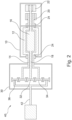
- Fig. 2 shows a schematic illustration showing a first implementation of the disclosed electrical motor arrangement according to Fig. 1 , whereby the electrical motor arrangement 10 is further comprising: a first brake unit 20 configured to brake the first rotational means 12; and a second brake unit 22 configured to brake the second rotational means 16.
- first rotational means 12 or the second rotational means 16 are partially and/or completely braked, in order that the braked rotation means 12, 16 are used as the stator of the electrical motor arrangement 10.
- the electrical motor arrangement 10 provide the rotational movement to a transmission arrangement 30 which is configured as a planetary gearbox 30. Therefore, in this example, the first rotational means 12 are rotational connected with the first torque transmission path 14 to planets 34 of the planetary gearbox 30 and the second rotational means 16 are rotational connected with the second torque transmission path 18 to the sun wheel 32 of the planetary gearbox 30.
- a ring gear 36 of the planetary gearbox is connected to an output shaft 42 to provide a rotational movement of the planetary gearbox 30.
- the electrical motor arrangement 10 is configured to operate alternately the first configuration or the second configuration.
- the electrical motor arrangement 10 is configured to be housed in at least a driven axle of the vehicle 40.
- Fig. 3 shows a schematic illustration showing a second implementation of the disclosed electrical motor arrangement according to Fig. 1 and Fig. 2 , whereby, in tis example, the second rotational means 16 are connected to at least one gear means 38 at least configured to decouple the second rotational means 16 and the sun wheel 32.
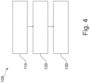
- Fig. 4 shows an example of a diagram of the disclosed method 100 for providing rotational movement for a transmission of a vehicle, comprising: providing 110 an electrical motor arrangement according to any one of the preceding claims; controlling 120 the electrical motor arrangement at least in a first configuration or in a second configuration; whereby in the first configuration, a first force receiving element of the transmission arrangement is driven and a second force receiving element of the transmission arrangement is braked and whereby in the second configuration, the second force receiving element is driven and the first force receiving element is braked; and providing 130 a first rotational movement and/or a second rotational movement to a transmission arrangement.
Landscapes
- Engineering & Computer Science (AREA)
- Power Engineering (AREA)
- Chemical & Material Sciences (AREA)
- Combustion & Propulsion (AREA)
- Transportation (AREA)
- Mechanical Engineering (AREA)
- Connection Of Motors, Electrical Generators, Mechanical Devices, And The Like (AREA)
- Electric Propulsion And Braking For Vehicles (AREA)
Abstract
An electrical motor arrangement for providing rotational movement for a transmission of a vehicle, comprising: a first rotational means (12) for providing a first rotational movement of the electrical motor arrangement (10); and a second rotational means (16) for providing a second rotational movement of the electrical motor arrangement (10); whereby in a first configuration, the first rotational means (12) is configured as a stator of the electrical motor arrangement (10) and the second rotational means (16) is configured as rotor of the electrical motor arrangement (10) and whereby in a second configuration, the first rotational means (12) is configured as a rotor of the electrical motor arrangement (10) and the second rotational means (16) is configured as stator of the electrical motor arrangement (10); whereby the first rotational movement and/or the second rotational movement is provided to a transmission arrangement (30).
Description
- The present disclosure relates to an electrical motor arrangement for providing rotational movement for a transmission of a vehicle, a method for providing rotational movement for a transmission of a vehicle, a vehicle with an electrical motor arrangement and/or a use of a planetary gearbox in an electrical motor arrangement.
- Known electrical motor arrangements comprise a stationary stator and a moveable rotor, whereby the motor arrangement generates a torque by an interaction of the stator and the rotor. This torque is transmitted to a driven axle of a vehicle via a gearbox or transmission, whereby continuous and smooth torque transmission is an issue, in particular when the transmission changes gears.
- In view of this, it is found that a further need exists to provide an electrical motor arrangement for providing rotational movement for a transmission of a vehicle.
- In the view of the above, it is an object of the present disclosure to provide an electrical motor arrangement for providing rotational movement for a transmission of a vehicle.
- The problem is at least partially solved or alleviated by the subject matter of the independent claims of the present disclosure, whereby further examples are incorporated in the dependent claims.
- According to a first aspect, an electrical motor arrangement for providing rotational movement for a transmission of a vehicle, comprising: a first rotational means for providing a first rotational movement of the electrical motor arrangement; and a second rotational means for providing a second rotational movement of the electrical motor arrangement; whereby in a first configuration, the first rotational means is configured as a stator of the electrical motor arrangement and the second rotational means is configured as a rotor of the electrical motor arrangement and whereby in a second configuration, the first rotational means is configured as a rotor of the electrical motor arrangement and the second rotational means is configured as a stator of the electrical motor arrangement; whereby the first rotational movement and/or the second rotational movement is provided to a transmission arrangement.
- The electrical motor arrangement may be configured as a three-phase motor, linear motor, AC (alternating current) motor, transverse flux machine, DC (direct current) motor, universal motor, repulsion motor, ball bearing motor, unipolar machine, and/or disc motor, in particular axial flux motor.
- The transmission of the vehicle may also be configured as the transmission arrangement. The rotational movement may for example be a rotational movement in order to transmit a torque or rotational force to the transmission.
- The first rotational means and/or the second rotational means may be configured as rotational/rotatably elements of the electrical motor arrangement for providing the rotational movement for the transmission. Furthermore, the first rotational means may comprise a first torque transmission path for providing the first rotational movement. Further, the second rotational means may comprise a second torque transmission path for providing the second rotational movement. Moreover, the first torque transmission path and/or the second torque transmission path may be used as a torque chain for the respective rotational means.
- In the first configuration, the second rotational means may be at least configured to provide the second rotational movement for the transmission unit. In the second configuration, the first rotational means may be at least configured to provide the first rotational movement for the transmission unit.
- Therefore the electrical motor arrangement may be configured to provide a torque for the transmission, whereby the torque may be provided in the first configuration by the second rotational means and whereby the torque may be provided in the second configuration by the first rotational means.
- In an implementation, the first rotational means may be arranged as an outer rotational means of the electrical motor arrangement and the second rotational means may be arranged as an inner rotational means of the electrical motor arrangement; or the first rotational means may be configured as a first rotation element of the electrical motor arrangement and the second rotational means may be configured as a second rotation element of the electrical motor arrangement.
- For example, if the first rotating means may be configured as the outer rotating means and the second rotating means may be configured as the inner rotating means, the electrical motor arrangement may be configured as an electric motor with radial rotating elements.
- Further, if the first rotational means may be configured as a first rotation element and the second rotational means may be configured as the second rotation element, the electrical motor arrangement may be configured as an electrical motor with axial rotating elements.
- In an implementation, the electrical motor arrangement may further comprise: a first brake unit may be configured to brake the first rotational means; and a second brake unit may be configured to brake the second rotational means.
- The first brake unit and/or the second brake unit may be configured in order to counteract the rotational movement of the first rotational means and/or the second rotational means at least in parts.
- In an implementation, a movement of the first rotational means or the second rotational means may be partially and/or completely braked, in order that the braked rotation means may be used as the stator of the electrical motor arrangement.
- In other words, in order to affect the resulting transmission ratio between the motor and the driven axis, each of the rotating parts may be fully or partially braked.
- In other implementations, the partial and/or full braking may be performed, for example, in order to facilitate a gear shifting.
- In an implementation, the transmission arrangement may be a planetary gearbox.
- In other words, the planetary gear may be planetary gear train, which may be configured as a gear train or friction gear, and therefore may comprise fixed shafts as well as axles, each of which rotates on circular paths in a frame. Accordingly, a distinction may be made between the central or sun gears mounted on the fixed axles of the frame and the planetary gears mounted on the rotating axles. Further, the wheels that rotate on the rotating axes may orbit a central wheel, similar to how planets orbit the sun. In turn, the rod supporting the rotating axles may rotate in order around an axle attached to the frame.
- In an implementation, the first rotational means may be connected to a sun wheel of the planetary gearbox and the second rotational means may be connected to planets of the planetary gearbox.
- In further implementation, an output of the planetary gearbox may be connected to a ring gear of the planetary gearbox.
- Further, the first rotational means may be connected to the sun wheel, the second rotational means may be connected to the ring gear and an output of the planetary gearbox may be connected to the planets.
- Further, the first rotational means may be connected to the ring gear, the second rotational means may be connected to the planets and an output of the planetary gearbox may be connected to the sun wheel.
- In an implementation, the first rotational mean and/or the second rotational means may be connected to at least one gear means at least configured to decouple the first rotational means and the sun wheel and/or the second rotational means and the planets.
- Furthermore, the at least one gear means may be configured to decouple the first rotational means and the respective transmission arrangement of the first rotational means and/or the second rotational means and the respective transmission arrangement of the second rotational means.
- In other embodiments, the first rotational mean and/or the second rotational means may be connected to at least one gear means at least configured to provide different ratios between the first rotational means and the sun wheel and/or the second rotational means and the planets.
- The at least one gear means may be configured with multiple gears in order to modify, for example, speed, direction of rotation, and/or torque of the first rotational movement and/or the second rotational movement.
- In an implementation, a ring gear of the planetary gearbox may be connected to an output shaft.
- The output shaft may be configured to provide the rotational movement of the electrical motor arrangement for the vehicle.
- In an implementation, the electrical motor arrangement may be configured to operate alternately the first configuration or the second configuration.
- For example, at a first time the electrical motor arrangement may be operated in the first configuration and at a second time the electrical motor arrangement may be operated in the second configuration, whereby after the second time the motor arrangement may be operated in the first configuration again, for example.
- Thereby, the first time may correspond to a use of a vehicle that is before and/or after activation of a gear change, and the second time may correspond to a use of the vehicle that is during activation of the gear change.
- Furthermore, the first time and/or the second time may comprise a different duration, whereby the duration of the respective times may for example depend on the respective use of the vehicle.
- In an implementation, in a third configuration, the first rotational means may be configured as a rotor of the electrical motor arrangement and the second rotational means may be configured as rotor of the electrical motor arrangement.
- For example, the third configuration may be configured so that both rotors may be used as main rotors, in particular in a two-speed transmission. In this case, the third configuration may be activated during a gear change whereby one rotor is brought to a standstill and the other rotor, which was previously static, is brought to rotation. In this case, the second rotor may not only rotate during the gear change, but it may also start to rotate during the gear change and after the gear change. In this respect, the gear change may take place between the torque paths and may be independent of whether a gear other than the main planetary gear is mounted on the torque paths.
- In other words, the third configuration may be used if the first rotational means and the second rotational means may be configured as rotors of the electrical motor arrangement. Therefore, the first rotational means or the second rotational means may be configured as a main rotor of the electrical motor arrangement for providing a rotational movement to the transmission unit and the second rotational means or the first rotational means may be configured as a secondary rotor of the electrical motor arrangement. In addition, the secondary rotor may be configured to rotate and transfer torque for a limited time through a secondary rotor torque path while a gear shift may occurs on the main rotor torque path.
- Moreover, once a gear change may be activated, the secondary rotor, for example the first rotational means or the second rotational means, may be gradually rotated until the main rotor stops, for example the second rotational means or the first rotational means, or rotates at a speed that facilitates the gear change in a main torque path. Once the gear change has occurred in the main torque path, the main rotor, for example the second rotational means or the first rotational means, may be gradually unlocked and the secondary rotor, for example the first rotational means or the second rotational means, may be gradually decelerated by the first brake unit and/or the second brake unit to a stop.
- The use of the first configuration, in which the first rotational means may be configured as a stator of the electrical motor arrangement and the second rotational means may be configured as a rotor of the electrical motor arrangement, and the second configuration, in which the first rotational means may be configured as a rotor of the electrical motor arrangement and the second rotational means may be configured as stator of the electrical motor arrangement, may in particular be used for a transmission of a rotational movement before and/or after a change of gear of a transmission.
- Furthermore, the use of the second configuration, in which the first rotational means is configured as a rotor of the electrical motor arrangement and the second rotational means is configured as rotor of the electrical motor arrangement, may in particular used for a change of gear of a transmission.
- Moreover, in particular a change between the first and the second to the third may preferably be used for example, in order to avoid additional efficiency losses or shortened product life that may be associated with allowing the secondary rotor to rotate (e.g., additional losses due to brushes).
- Further, for example, the vehicle may be operated primarily with the main rotor torque chain whereby the secondary rotor may be stationary until a gear change is required. Once the gear shift is activated the secondary rotor may, for example, gradually rotate until the main rotor is stationary or rotating at a speed that facilitates the gear shift on the main torque path. For example, once gear shifting occurs on the main torque path, the main rotor may be gradually unlocked and the secondary rotor gradually decelerated to a stop.
- In an implementation, the electrical motor arrangement may be configured to be housed in at least a driven axle of the vehicle.
- In an embodiment, the vehicle may be driven primarily with the main rotor torque chain engaged and the secondary rotor stationary until a gear change is required. Once the gear change is activated, the secondary rotor may gradually rotate until the main rotor is stationary or rotating at a speed that facilitates the gear shift in the main torque path. Once the gear change has occurred in the main torque path, the main rotor may be gradually unlocked and the secondary rotor gradually decelerated to a stop.
- Thereby, for example, applying brakes on the inner rotor and forcing it to be at standstill while allowing the outer rotor only to rotate may result in a total gear ratio of a rotation of the electrical motor arrangement of Router. Moreover, applying brakes on the outer rotor and forcing it to be at standstill while allowing the inner rotor only to rotate may be result in a total gear ratio of a rotation of the electrical motor arrangement of Rinner.
- Furthermore, an example of the application may be a two-speed gearbox where Router and Rinner represent the speed of two gears. By locking the inner rotor, torque may be transmitted with Router, while by locking the outer rotor, torque may be transmitted with Rinner. When shifting between Router and Rinner, for example, the brakes on the inner rotor may be released gradually, and the brakes may be engaged on the outer rotor until it reaches standstill. During the transitional period, the gear ratio may be gradually changed between the two limit ratios Router and Rinner. This may ensure that during shifting, the torque may never be interrupted on the wheels, and the transmission occurs smoothly.
- A further aspect of the present disclosure relates to a method for providing rotational movement for a transmission of a vehicle, comprising: providing an electrical motor arrangement according to any one of the preceding claims; controlling the electrical motor arrangement at least in a first configuration or in a second configuration; whereby in the first configuration, a first force receiving element of the transmission arrangement is driven and a second force receiving element of the transmission arrangement is braked and whereby in the second configuration, the second force receiving element is driven and the first force receiving element is braked; and providing a first rotational movement and/or a second rotational movement to a transmission arrangement.
- In an implementation, the controlling of the electrical motor arrangement may further comprise: controlling the electrical motor arrangement in a third configuration, whereby in the third configuration, the planets and the sun wheel are driven.
- A further aspect of the present disclosure relates to a vehicle with the disclosed electrical motor arrangement, whereby the electrical motor arrangement is housed in an electrical motor arrangement housing of the vehicle.
- A further aspect of the present disclosure relates to a use of a planetary gearbox in the disclosed electrical motor arrangement and/or in the disclosed vehicle.
- In the following, the disclosure is described exemplarily with reference to the enclosed figures, in which:
- Fig. 1
- is a schematic illustration showing an overview of an implementation of the disclosed electrical motor arrangement;
- Fig. 2
- is a schematic illustration showing a first implementation of the disclosed electrical motor arrangement;
- Fig. 3
- is a schematic illustration showing a second implementation of the disclosed electrical motor arrangement; and
- Fig. 4
- is an example of a diagram of the disclosed method.
- Notably, the figures are merely schematic representations and serve only to illustrate examples of the present disclosure. Identical or equivalent elements are in principle provided with the same reference signs.
-
Fig. 1 shows a schematic illustration showing an overview of an implementation of the disclosed electrical motor arrangement for providing rotational movement for a transmission of a vehicle, comprising: a first rotational means 12 for providing a first rotational movement of theelectrical motor arrangement 10; and a second rotational means 16 for providing a second rotational movement of theelectrical motor arrangement 10; whereby in a first configuration, the first rotational means 12 is configured as a stator of theelectrical motor arrangement 10 and the second rotational means 16 is configured as rotor of theelectrical motor arrangement 10 and whereby in a second configuration, the first rotational means 12 is configured as a rotor of theelectrical motor arrangement 10 and the second rotational means 16 is configured as stator of theelectrical motor arrangement 10; whereby the first rotational movement and/or the second rotational movement is provided to atransmission arrangement 30. - Further, the first rotational means 12 is arranged as an outer rotational means 12 of the
electrical motor arrangement 10 and the second rotational means 16 is arranged as an inner rotational means 16 of theelectrical motor arrangement 10. - Further, the first rotational means 12 provides the first rotational movement by a first
torque transmission path 14 and the second rotational means 16 provides the second rotational movement by a secondtorque transmission path 18. - In addition, the electrical motor arrangement comprises
bearings 24 in order to mount the first rotational means 12, the firsttorque transmission path 14, the second rotational means 16 and/or the secondtorque transmission path 18. -
Fig. 2 shows a schematic illustration showing a first implementation of the disclosed electrical motor arrangement according toFig. 1 , whereby theelectrical motor arrangement 10 is further comprising: afirst brake unit 20 configured to brake the first rotational means 12; and asecond brake unit 22 configured to brake the second rotational means 16. - Furthermore, a movement of the first rotational means 12 or the second rotational means 16 is partially and/or completely braked, in order that the braked rotation means 12, 16 are used as the stator of the
electrical motor arrangement 10. - Further, the
electrical motor arrangement 10 provide the rotational movement to atransmission arrangement 30 which is configured as aplanetary gearbox 30. Therefore, in this example, the first rotational means 12 are rotational connected with the firsttorque transmission path 14 toplanets 34 of theplanetary gearbox 30 and the second rotational means 16 are rotational connected with the secondtorque transmission path 18 to thesun wheel 32 of theplanetary gearbox 30. - Further, a
ring gear 36 of the planetary gearbox is connected to anoutput shaft 42 to provide a rotational movement of theplanetary gearbox 30. - Moreover, the
electrical motor arrangement 10 is configured to operate alternately the first configuration or the second configuration. - In addition, the
electrical motor arrangement 10 is configured to be housed in at least a driven axle of thevehicle 40. -
Fig. 3 shows a schematic illustration showing a second implementation of the disclosed electrical motor arrangement according toFig. 1 andFig. 2 , whereby, in tis example, the second rotational means 16 are connected to at least one gear means 38 at least configured to decouple the second rotational means 16 and thesun wheel 32. -
Fig. 4 shows an example of a diagram of the disclosedmethod 100 for providing rotational movement for a transmission of a vehicle, comprising: providing 110 an electrical motor arrangement according to any one of the preceding claims; controlling 120 the electrical motor arrangement at least in a first configuration or in a second configuration; whereby in the first configuration, a first force receiving element of the transmission arrangement is driven and a second force receiving element of the transmission arrangement is braked and whereby in the second configuration, the second force receiving element is driven and the first force receiving element is braked; and providing 130 a first rotational movement and/or a second rotational movement to a transmission arrangement. - Other variations to the disclosed examples may be understood and effected by those skilled in the art in practicing the claimed subject matter, from the study of the figures, the disclosure, and the appended claims. In particular, respective parts/functions of the respective example described above may also be combined with each other. In particular, the present disclosure is not limited to specific modules, vehicle functions, user interfaces, user interface areas/fields and/or communication methods. In the claims, the word "comprising" does not exclude other elements or steps and the indefinite article "a" or "an" does not exclude a plurality. The mere fact that certain measures are recited in mutually different dependent claims does not indicate that a combination of these measures may not be used to advantage. Any reference signs in the claims should not be construed as limiting the scope of the claims.
-
- 10
- electrical motor arrangement
- 12
- first rotational means
- 14
- first torque transmission path
- 16
- second rotational means
- 18
- second torque transmission path
- 20
- first brake unit
- 22
- second brake unit
- 24
- bearings
- 30
- transmission arrangement (planetary gearbox)
- 32
- sun wheel
- 34
- planets
- 36
- ring gear
- 38
- gear means
- 40
- vehicle
- 42
- output shaft
- 100
- Method for providing rotational movement
- 110
- providing an electrical motor arrangement
- 120
- controlling the electrical motor arrangement
- 130
- providing a first rotational movement and/or a second rotational movement
Claims (15)
- Electrical motor arrangement for providing rotational movement for a transmission of a vehicle, comprising:a first rotational means (12) for providing a first rotational movement of the electrical motor arrangement (10); anda second rotational means (16) for providing a second rotational movement of the electrical motor arrangement (10);whereby in a first configuration, the first rotational means (12) is configured as a stator of the electrical motor arrangement (10) and the second rotational means (16) is configured as rotor of the electrical motor arrangement (10) and whereby in a second configuration, the first rotational means (12) is configured as a rotor of the electrical motor arrangement (10) and the second rotational means (16) is configured as stator of the electrical motor arrangement (10);whereby the first rotational movement and/or the second rotational movement is provided to a transmission arrangement (30).
- The electrical motor arrangement according to claim 1, whereby the first rotational means (12) is arranged as an outer rotational means (12) of the electrical motor arrangement (10) and the second rotational means (16) is arranged as an inner rotational means (16) of the electrical motor arrangement (10); or the first rotational means (12) is configured as a first rotation element (12) of the electrical motor arrangement (10) and the second rotational means (16) is configured as a second rotation element (16) of the electrical motor arrangement (10).
- The electrical motor arrangement according to claim 1 or 2, whereby the electrical motor arrangement (10) is further comprising:a first brake unit (20) configured to brake the first rotational means (12); anda second brake unit (22) configured to brake the second rotational means (16).
- The electrical motor arrangement according to claim 3, whereby a movement of the first rotational means (12) or the second rotational means (16) is partially and/or completely braked, in order that the braked rotation means (12, 16) are used as the stator of the electrical motor arrangement (10).
- The electrical motor arrangement according to any one of the preceding claims, whereby the transmission arrangement (30) is a planetary gearbox (30).
- The electrical motor arrangement according to claim 5, whereby the first rotational means (12) are connected to a sun wheel (32) of the planetary gearbox (30) and the second rotational means (16) are connected to planets (34) of the planetary gearbox (30).
- The electrical motor arrangement according to claim 6, whereby the first rotational mean (12) and/or the second rotational means (16) are connected to at least one gear means (38) at least configured to decouple the first rotational means (12) and the sun wheel (32) and/or the second rotational means (16) and the planets (34).
- The electrical motor arrangement according to claim 5 to 7, whereby a ring gear (36) of the planetary gearbox (30) is connected to an output shaft (42).
- The electrical motor arrangement according to any one of the preceding claims, whereby the electrical motor arrangement (10) is configured to operate alternately the first configuration or the second configuration.
- The electrical motor arrangement according to any one of the preceding claims, whereby in a third configuration, the first rotational means (12) is configured as a rotor of the electrical motor arrangement (10) and the second rotational means (16) is configured as rotor of the electrical motor arrangement (10).
- The electrical motor arrangement according to any one of the preceding claims, whereby the electrical motor arrangement (10) is configured to be housed in at least a driven axle of the vehicle (40).
- Method for providing rotational movement for a transmission of a vehicle, comprising:providing (110) an electrical motor arrangement (10) according to any one of the preceding claims;controlling (120) the electrical motor arrangement (10) at least in a first configuration or in a second configuration;whereby in the first configuration, a first force receiving element of the transmission arrangement is driven and a second force receiving element of the transmission arrangement is braked and whereby in the second configuration, the second force receiving element is driven and the first force receiving element is braked; andproviding (130) a first rotational movement and/or a second rotational movement to a transmission arrangement.
- The method according to claim 12, whereby the controlling (120) of the electrical motor arrangement (10) is further comprising: controlling (120) the electrical motor arrangement (10) in a third configuration, whereby in the third configuration, the planets and the sun wheel are driven.
- Vehicle with an electrical motor arrangement (10) according to any one of the claims 1 to 11, whereby the electrical motor arrangement (10) is housed in an electrical motor arrangement housing of the vehicle (40).
- Use of a planetary gearbox (30) in an electrical motor arrangement (10) according to any one of the claims 1 to 11 and/or in a vehicle according to claim 14.
Priority Applications (3)
| Application Number | Priority Date | Filing Date | Title |
|---|---|---|---|
| EP23165984.8A EP4439941A1 (en) | 2023-03-31 | 2023-03-31 | Improved electrical motor arrangement |
| CN202410318141.1A CN118739774A (en) | 2023-03-31 | 2024-03-20 | Improved motor equipment |
| US18/620,510 US12466253B2 (en) | 2023-03-31 | 2024-03-28 | Electrical motor arrangement |
Applications Claiming Priority (1)
| Application Number | Priority Date | Filing Date | Title |
|---|---|---|---|
| EP23165984.8A EP4439941A1 (en) | 2023-03-31 | 2023-03-31 | Improved electrical motor arrangement |
Publications (1)
| Publication Number | Publication Date |
|---|---|
| EP4439941A1 true EP4439941A1 (en) | 2024-10-02 |
Family
ID=85800476
Family Applications (1)
| Application Number | Title | Priority Date | Filing Date |
|---|---|---|---|
| EP23165984.8A Pending EP4439941A1 (en) | 2023-03-31 | 2023-03-31 | Improved electrical motor arrangement |
Country Status (3)
| Country | Link |
|---|---|
| US (1) | US12466253B2 (en) |
| EP (1) | EP4439941A1 (en) |
| CN (1) | CN118739774A (en) |
Families Citing this family (1)
| Publication number | Priority date | Publication date | Assignee | Title |
|---|---|---|---|---|
| EP4439941A1 (en) * | 2023-03-31 | 2024-10-02 | Volvo Car Corporation | Improved electrical motor arrangement |
Citations (2)
| Publication number | Priority date | Publication date | Assignee | Title |
|---|---|---|---|---|
| GB2483673A (en) * | 2010-09-14 | 2012-03-21 | Romax Technology Ltd | Hybrid power train |
| DE102011084092A1 (en) * | 2011-10-06 | 2013-04-11 | Bayerische Motoren Werke Aktiengesellschaft | Electric machine i.e. prime mover, for transforming excess kinetic energy into electric energy in battery of motor car, has stator and rotor mounted independently to one another, where stator is connected or detached with housing |
Family Cites Families (9)
| Publication number | Priority date | Publication date | Assignee | Title |
|---|---|---|---|---|
| DE20303611U1 (en) * | 2003-03-07 | 2004-05-27 | Ripperger, Lucian, Dipl.-Ing. | Electric motor has rotor and stator that are coupled with each other for generating opposed rotation movement |
| US7591748B2 (en) * | 2006-08-29 | 2009-09-22 | Gm Global Technology Operations, Inc. | Electrically variable transmission with a compound motor/generator |
| US8253294B1 (en) * | 2008-05-02 | 2012-08-28 | E-Wish Technology, Llc | Increased efficiency dual rotational electric motor/generator |
| GB2466967B (en) * | 2009-01-16 | 2013-09-25 | Gm Global Tech Operations Inc | Drive mechanism for selectively switching a drive between propulsion and torque vectoring mode |
| EP2578438B1 (en) * | 2012-01-10 | 2017-04-26 | Volvo Car Corporation | Dual shaft motor |
| DE102013213323A1 (en) * | 2013-07-08 | 2015-01-08 | Schaeffler Technologies Gmbh & Co. Kg | Rotary element for a vehicle device |
| DE102017110581B4 (en) * | 2017-05-16 | 2019-05-16 | Iav Gmbh Ingenieurgesellschaft Auto Und Verkehr | Vehicle drive device |
| KR20230140805A (en) * | 2022-03-30 | 2023-10-10 | 현대자동차주식회사 | Dual rotor motor and hybrid powertrain using thereof |
| EP4439941A1 (en) * | 2023-03-31 | 2024-10-02 | Volvo Car Corporation | Improved electrical motor arrangement |
-
2023
- 2023-03-31 EP EP23165984.8A patent/EP4439941A1/en active Pending
-
2024
- 2024-03-20 CN CN202410318141.1A patent/CN118739774A/en active Pending
- 2024-03-28 US US18/620,510 patent/US12466253B2/en active Active
Patent Citations (2)
| Publication number | Priority date | Publication date | Assignee | Title |
|---|---|---|---|---|
| GB2483673A (en) * | 2010-09-14 | 2012-03-21 | Romax Technology Ltd | Hybrid power train |
| DE102011084092A1 (en) * | 2011-10-06 | 2013-04-11 | Bayerische Motoren Werke Aktiengesellschaft | Electric machine i.e. prime mover, for transforming excess kinetic energy into electric energy in battery of motor car, has stator and rotor mounted independently to one another, where stator is connected or detached with housing |
Also Published As
| Publication number | Publication date |
|---|---|
| US20240326584A1 (en) | 2024-10-03 |
| CN118739774A (en) | 2024-10-01 |
| US12466253B2 (en) | 2025-11-11 |
Similar Documents
| Publication | Publication Date | Title |
|---|---|---|
| CA2398181C (en) | Electric drive for a vehicle | |
| AU745277B2 (en) | Drive mechanism for a vehicle, especially a multilane electromobile | |
| US10203028B2 (en) | Drive gear unit | |
| US7469858B2 (en) | Geared wheel motor design | |
| EP3248822B1 (en) | In-wheel motor | |
| CN109017271B (en) | Electric automobile and power driving device thereof | |
| US11181177B2 (en) | Torque vectoring device | |
| JP2006258289A (en) | In-wheel motor drive unit | |
| KR20030038346A (en) | Rotating electrical device | |
| US12466253B2 (en) | Electrical motor arrangement | |
| EP3396206A1 (en) | Geared transmission unit | |
| WO2005035358A2 (en) | Geared wheel motor design | |
| US11796042B2 (en) | Continuously variable transmission | |
| US20120013211A1 (en) | Electric motor having a selectively adjustable base speed | |
| CN120886230A (en) | Dual-stator single-rotor planetary reduction joint module | |
| US2571172A (en) | Transmission device | |
| CN210405049U (en) | Double-rotor motor | |
| CN103244362B (en) | Wind-powered electricity generation perseverance braking permanent magnetism driftage-pitch cycloid speed reducer | |
| CN100559048C (en) | A kind of reverse converter | |
| CN212726728U (en) | Speed reducing motor | |
| CN209669537U (en) | Double bevel gear differential speed reduction mechanism for pulsator washing machine | |
| CN101403431A (en) | Split differential high-efficiency self-locking mechanism | |
| US12377719B2 (en) | Drive device for a drive shaft comprising two rotating machines | |
| JP2022158060A (en) | drive unit | |
| CN217307452U (en) | Permanent magnet brake structure of tubular motor |
Legal Events
| Date | Code | Title | Description |
|---|---|---|---|
| PUAI | Public reference made under article 153(3) epc to a published international application that has entered the european phase |
Free format text: ORIGINAL CODE: 0009012 |
|
| STAA | Information on the status of an ep patent application or granted ep patent |
Free format text: STATUS: REQUEST FOR EXAMINATION WAS MADE |
|
| 17P | Request for examination filed |
Effective date: 20231220 |
|
| AK | Designated contracting states |
Kind code of ref document: A1 Designated state(s): AL AT BE BG CH CY CZ DE DK EE ES FI FR GB GR HR HU IE IS IT LI LT LU LV MC ME MK MT NL NO PL PT RO RS SE SI SK SM TR |
|
| STAA | Information on the status of an ep patent application or granted ep patent |
Free format text: STATUS: EXAMINATION IS IN PROGRESS |