EP4439885A1 - Robot for displacement through medium and high voltage electrical lines - Google Patents
Robot for displacement through medium and high voltage electrical lines Download PDFInfo
- Publication number
- EP4439885A1 EP4439885A1 EP24020096.4A EP24020096A EP4439885A1 EP 4439885 A1 EP4439885 A1 EP 4439885A1 EP 24020096 A EP24020096 A EP 24020096A EP 4439885 A1 EP4439885 A1 EP 4439885A1
- Authority
- EP
- European Patent Office
- Prior art keywords
- robot
- line
- high voltage
- motor
- moving along
- Prior art date
- Legal status (The legal status is an assumption and is not a legal conclusion. Google has not performed a legal analysis and makes no representation as to the accuracy of the status listed.)
- Withdrawn
Links
Images




Classifications
-
- H—ELECTRICITY
- H02—GENERATION; CONVERSION OR DISTRIBUTION OF ELECTRIC POWER
- H02G—INSTALLATION OF ELECTRIC CABLES OR LINES, OR OF COMBINED OPTICAL AND ELECTRIC CABLES OR LINES
- H02G1/00—Methods or apparatus specially adapted for installing, maintaining, repairing or dismantling electric cables or lines
- H02G1/02—Methods or apparatus specially adapted for installing, maintaining, repairing or dismantling electric cables or lines for overhead lines or cables
-
- B—PERFORMING OPERATIONS; TRANSPORTING
- B25—HAND TOOLS; PORTABLE POWER-DRIVEN TOOLS; MANIPULATORS
- B25J—MANIPULATORS; CHAMBERS PROVIDED WITH MANIPULATION DEVICES
- B25J9/00—Program-controlled manipulators
- B25J9/10—Program-controlled manipulators characterised by positioning means for manipulator elements
-
- G—PHYSICS
- G01—MEASURING; TESTING
- G01R—MEASURING ELECTRIC VARIABLES; MEASURING MAGNETIC VARIABLES
- G01R31/00—Arrangements for testing electric properties; Arrangements for locating electric faults; Arrangements for electrical testing characterised by what is being tested not provided for elsewhere
-
- H—ELECTRICITY
- H02—GENERATION; CONVERSION OR DISTRIBUTION OF ELECTRIC POWER
- H02G—INSTALLATION OF ELECTRIC CABLES OR LINES, OR OF COMBINED OPTICAL AND ELECTRIC CABLES OR LINES
- H02G7/00—Overhead installations of electric lines or cables
- H02G7/05—Suspension arrangements or devices for electric cables or lines
- H02G7/053—Suspension clamps and clips for electric overhead lines not suspended to a supporting wire
Definitions
- patent ES 2 575 737 A1 There is a self-propelled vehicle covered by patent ES 2 575 737 A1 , which moves along the high voltage lines by an additional cable which is installed in the line and that further has no voltage, which complicates its installation.
- This invention that is exposed represents a large innovation in providing a solution to such a complicated aspect with a simple, light robot that is capable of moving at relatively high speeds in an agile manner along medium and high voltage lines, without installation problems.
- this robot is intended for inspection tasks, with autonomous capacity, it is programmable with the grid structure (although it could detect it by itself). It will be able to move autonomously and take the data and images to be transmitted to a SCADA (Supervisory Control and Data Acquisition) system housed remotely which will process and analyze data to send new commands or requests to the robot, when appropriate.
- SCADA Supervisory Control and Data Acquisition
- each clip and at the bottom all the components, mechanisms and electronics will be housed, within what is hereinafter referred to as supervisor; cameras (optical, infrared), distance detectors (ultrasonic and laser), as well as motors or servomotors for its operation, a controller for all the necessary electronics like an iOS and a minicomputer, for example raspberry pi, to carry out the assigned automation and communication tasks, using the appropriate software connected to the SCADA system (what is provided as an example is what was initially used but due to the needs of the final design it may be varied).
- the robot's protection layers will be: electrical, inductive, and mechanical; the layers are the same throughout the apparatus and are composed of an outer polymeric insulation, a metallic shielding, a semiconductive layer, another inner insulation, and a mechanical protection casing.
- Placement on the line can be made by manual means by means of an insulated maneuvering pole, which holds the robot by the apex of the connecting rods, in the inverted position and once clamped to the lines, it is rotated 180° to remain in its normal operating position. It may also be coupled, by a drone that raises it with two "Y"-shaped arms that hold it by the connecting rods of the supervisors near them.
- the schematic representation of the robot is Figure 2 .
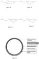
- Figure 22 is represented the section of the connecting rod indicating the protection layers.
- Figure 2 the robot can be seen, composed of the two supervisors, on the top are the clips, Figures 3 to 5 , which are responsible for clamping the robot to the line and movement therethrough, below are the two supervisors of the robot in which the electronics and mechanical elements that can be seen in Figure 23 which are essentially the following are distributed:
- the connecting rod of the two modules, Figures 24 and 25 which further are the two arms that together with the connecting ball joint, like a wrist, the supervisors like a hand and the clip like fingers make up the robot, with capacity of movement through the switchgear of the power lines.
- this invention can be applied to the inspection tasks of medium and high voltage lines, providing a large amount of data to determine the status and predict possible anomalies that can disturb the normal operation thereof. All this in record time with a lower cost than the current one and with greater safety for the operators in charge of this work.
Landscapes
- Engineering & Computer Science (AREA)
- Physics & Mathematics (AREA)
- General Physics & Mathematics (AREA)
- Robotics (AREA)
- Mechanical Engineering (AREA)
- Manipulator (AREA)
Abstract
The robot for moving along medium and high voltage power lines is capable of moving along the line and avoiding most of the switchgear, collecting all the data and images necessary to study its current status and predict possible incidents in order to carry out corrective and preventive maintenance before it affects the continuity of supply. The robot is ideal for reporting the status of the installation, reducing the time and resources used in the inspection while increasing the number of daily kilometers analyzed.
Description
- ELECTRICAL SECTOR: in this sector, currently a large amount of human resources is being allocated to grid inspection and maintenance tasks, which represents a large amount of economic resources. These inspections are being performed mostly on foot, which makes them slow, in some cases they are being made with helicopters, which makes them very expensive and are currently being made with drones, which makes them dangerous. Since it is a strategic sector that is increasingly indispensable in the everyday life of citizens and its work activity implies large and serious risks, it deserves a technological innovation that allows work to be performed by minimizing risks and optimizing inspection and preventive maintenance operations that guarantee supply.
- Once tested on the Internet and in the Patent and Trademark Office, some approaches are found that in some cases are far apart from addressing the three larger problems faced by this type of apparatus, which are: the presence of very high voltages and non-negligible intensities, the strong magnetic fields to which the apparatus working under these conditions are subjected and the challenge of moving along the line advancing from one span of the conductor to another, which is delimited by the supports, and the passage of the various elements of the complex switchgear of the power lines.
- There is a self-propelled vehicle covered by
patent ES 2 575 737 A1 - There is also an autonomous inspection system with
patent ES 1 152 085 U - A system for inspection of power lines was patented from Peru under the number
PCT/PE2017/000033 - In the US there is a device such as "Expliner" that moves along two conductors of the same circuit, it is cumbersome and bulky, in addition to requiring two conductors for its movement.
- Also, in the US there is the "SkySweeper" which is a robot project that moves through jumps and that is not developed to run along a live line, these jumps produce vibrations in the conductors, which can cause breakdowns due to short-circuits in the grid.
- This invention that is exposed represents a large innovation in providing a solution to such a complicated aspect with a simple, light robot that is capable of moving at relatively high speeds in an agile manner along medium and high voltage lines, without installation problems.
- Initially this robot is intended for inspection tasks, with autonomous capacity, it is programmable with the grid structure (although it could detect it by itself). It will be able to move autonomously and take the data and images to be transmitted to a SCADA (Supervisory Control and Data Acquisition) system housed remotely which will process and analyze data to send new commands or requests to the robot, when appropriate. The robot circulates suspended from the line and by the bottom of the conductor.
- This same robot can be provided with articulated arms with the appropriate claws for repair and maintenance tasks. The solutions to the three groups of major problems presented by actuations in a live electrical grid are basically described below, which are described in the four sections:
- 1- Isolation of the voltages and intensities present in the conductor, as it is an apparatus clamped to a single cable, it works at potential and avoids touching other parts or elements of the line that are not at the same voltage, as well as objects foreign to the line close thereto, this way we avoid having potential differences. That is why it only needs a certain degree of insulation so that dangerous voltages and intensities do not occur between the two clamping clips of the robot, which do not affect the electronics. Nothing that cannot be addressed with external polymeric insulation similar to that of insulators. Taking into account that most cables are made of aluminum and its electrical resistance is 3,2110-8 Ωm, being a relatively small distance, the resistance will not reach in any case high values, they can be between 6,4220-8 Ω and 9,630-8 Ω in a first estimate. Thus, if we have practically no potential differences and the resistances are small, the intensities are also negligible. In addition, its "V" shape moves the sensitive parts sufficiently away so that electric shocks do not occur.
- 2- Regarding the induction considering that the electronics of the apparatus is housed inside, to avoid possible adverse effects of this, the robot will be provided of a metallic shielding between the external insulation and another one internal, which isolates the casing mechanically protecting all the robot's electronics.
- Attached to each clip and at the bottom all the components, mechanisms and electronics will be housed, within what is hereinafter referred to as supervisor; cameras (optical, infrared), distance detectors (ultrasonic and laser), as well as motors or servomotors for its operation, a controller for all the necessary electronics like an Arduino and a minicomputer, for example raspberry pi, to carry out the assigned automation and communication tasks, using the appropriate software connected to the SCADA system (what is provided as an example is what was initially used but due to the needs of the final design it may be varied).
- The robot's protection layers will be: electrical, inductive, and mechanical; the layers are the same throughout the apparatus and are composed of an outer polymeric insulation, a metallic shielding, a semiconductive layer, another inner insulation, and a mechanical protection casing.
- 3.2- The top of both supervisors will be formed by the clip which will be responsible for clamping to the cable and providing linear movement to the robot. This clip will be something similar to a "V" with oval walls. At the top of the clip there will be at least three bearings which will serve as a guide and support. On the bottom it will have a drive wheel, which will provide enough traction to move the robot, the walls of the "V" will be joined with a joint which allows the opening and closing movement to clamp and release the cable. As an additional safety measure, it will have a lock, which is not shown in the drawing, which ensures the closing and prevents accidental detachment. The approximate appearance of the clip will be that of the herein accompanying drawing,
Figures 3, 4 and 5 . - 4- Explanation of the process of jumping over obstacles, normal movement along the cable is guided by the sensors available on the robot. These detect the distance to nearby objects and that with artificial intelligence software (Al), once trained by machine learning, the type of object is distinguished and if they are foreign or belong to the line, analyzing if it is necessary to go back or they can be passed to continue its travel. In any case, it will reduce speed and stop, identifying the type of obstacle before starting the maneuver.
- By way of example, the steps for operation of the passage of a tether support are indicated. If we call the
Supervisor 1 "A" and theSupervisor 2, "B", and we understand that the robot is traveling in the "A→B" direction. The "B" part close to the first tethering clip is separated from the conductor and moved downward, at the same time that it is drawn forward, the part "A" moves slightly forward as well, then the part "B" will rise and connect to the conductor once the first clip is passed, then the part "A" will be detached from the conductor and will go down while the part "B" moves forward (if necessary), the part is then raised again and clamped to the conductor between the two clips, a similar motion is then performed with the next clip until it can be matched after the support and continuing with normal travel along the conductor. - For higher voltage lines, wherein induction and arc effect are greater, a small modification of the design may be necessary to avoid problems of both electrical and magnetic isolation. In that case the distance sensors and chambers of the two supervisors would be displaced to a sphere located at the apex of the connecting rods, which is depicted in
Figure 25 , the result will be a greater insulation of the apparatus. - Placement on the line can be made by manual means by means of an insulated maneuvering pole, which holds the robot by the apex of the connecting rods, in the inverted position and once clamped to the lines, it is rotated 180° to remain in its normal operating position. It may also be coupled, by a drone that raises it with two "Y"-shaped arms that hold it by the connecting rods of the supervisors near them.
- Identification of the robot components, both of the two supervisors (main modules) and of the connecting rod therefrom.
- 1
- Motor for the clip safety lock
- 2
- Motor for the opening and closing movement of the clip [this is duplicated for safety]
- 3
- Motor of the drive wheel
- 4
- Motor for the vertical movement of the conical motion ball joint
- 5
- Motor for the horizontal movement of the conical motion ball joint
- 6
- Ultrasonic [or laser] distance detector
- 7
- Laser distance detector
- 8
- Optical camera
- 9
- Thermal chamber
- 10
- Data bus, command bus, and system power supply
- 11
- Electronic components controller
- 12
- System processor
- 13
- GPS controller
- 14
- Memory unit
- 15
- Communication module
- 16
- System power module and battery charger
- 17
- Coils for induction charging the system
- 18
- Battery
- 19
- Motor for the angular movement of the connecting rods
- 20
- GPS antenna
- 21
- Communication antenna
- 22
- Insulator, protection, and output of the antennas
- 23
- Chamber 360
- Piece with conical movement
Figure 1 placed between the supervisors and the rod. - The schematic representation of the robot is
Figure 2 . - The fastening clips
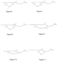
Figures 3, 4 and 5 . - Movement passage of a support with two tethering clips, in the sequence of figures between
Figure 6 to Figure 21 . - In
Figure 22 is represented the section of the connecting rod indicating the protection layers. - Exploded view of the two supervisors of the robot
Figure 23 . - The connecting rod of the main modules
Figures 24 and25 . - In view of the aforementioned figures, and according to the adopted numbering, a preferred embodiment of the invention can be seen therein, which comprises the parts and elements indicated and described in detail below.
- In
Figure 2 the robot can be seen, composed of the two supervisors, on the top are the clips,Figures 3 to 5 , which are responsible for clamping the robot to the line and movement therethrough, below are the two supervisors of the robot in which the electronics and mechanical elements that can be seen inFigure 23 which are essentially the following are distributed: - a motor (1), which moves a safety lock of the clip.
- two motors (2), which open and close the clip to be clamped to the conductor.
- a motor, which moves the wheel that is in contact with the conductor (3) and produces movement of the equipment along the line.
- a motor (4), which gives the connecting piece between the supervisor and the connecting rod the vertical movement.
- a motor (5), which gives the connecting piece between the supervisor and the connecting rod the horizontal movement.
- an ultrasound or laser distance detector (6), which prevents the robot from colliding with any element foreign to the line close thereto.
- a laser distance detector (7), which prevents the robot from colliding with any element belonging to the line lying on its way.
- an optical chamber (8), which collects the line status images and all of its components, supports, isolating crossbars as well as the environment within the line protection zone.
- a thermal chamber (9), which captures the status of the elements subjected to current and its isolation, for detecting hot spots that can cause an anomaly in the supply.
- the electronics wiring (10), which connects the processor and the control unit with all electronic elements of the robot.
- a controller (11), which coordinates all of the motors, sensors, and communicates with the central unit.
- a central unit (12), which processes all data collected by the robot, processes them and gives the commands to the controller for proper operation, in addition to communicating with the exterior positioning the images with the GPS (13) and sending them to the internal memory (14) or the central system for important analysis in need of greater calculation potential, this operation is performed through the communication module (15) and the antenna (21).
- a coil (17) will be installed which, taking advantage of the induction of the line, will charge the batteries (18) that power the system, in parallel with the charger located in the power module (16).
- a motor (19), which will provide angular movement to the connecting rods of the two supervisors of the robot.
- an insulator (22) conveniently placed at the furthest end of the line to allow for the output of the antennas (20 and 21) as well as a camera 360 (23) that will provide the images to collect the line protection space.
- The connecting rod of the two modules,
Figures 24 and25 , which further are the two arms that together with the connecting ball joint, like a wrist, the supervisors like a hand and the clip like fingers make up the robot, with capacity of movement through the switchgear of the power lines. - Finally, this invention can be applied to the inspection tasks of medium and high voltage lines, providing a large amount of data to determine the status and predict possible anomalies that can disturb the normal operation thereof. All this in record time with a lower cost than the current one and with greater safety for the operators in charge of this work.
Claims (5)
- Robot for moving along medium and high voltage lines, and which can avoid the elements that make up the structure of the line, characterized in that it comprises two supervisors at the top joined together by articulated arms formed by connecting rods with a connecting ball joint, giving the robot a "V" shape, wherein each supervisor comprisesa clamping clip comprising at least three guide and support bearings at the top and a drive wheel at the bottom for the movement of the robot,internally at least comprises one motor (1) that moves a safety lock of the clamp; two motors (2) that open and close the clip for clamping to the conductor; a motor that moves the wheel that is in contact with the conductor (3) and produces the movement of the equipment along the line; a motor (4) that gives the connecting piece between the supervisor and the connecting rod the vertical movement; a motor (5) that gives the connecting piece between the supervisor and the connecting rod the horizontal movement;a power supply module (16) of the system.an ultrasonic or laser distance detector (6) for detecting any element foreign to the line close to the robot;a laser distance detector (7) for detecting any element belonging to the line in the robot's way;an optical camera (8) for collecting images of the line status;a thermal camera (9) for detecting hot spots that may cause anomalies in the supply;a GPS (13), a communication module (15) and an antenna (21);an electronics wiring (10) connecting a controller and a control unit with all the electronic elements of the robot;a controller (11) coordinating all the motors, sensors and communicating them with the central unit;a central unit (12) processing and sending all the data collected by the robot;and wherein each connecting rod comprises a motor (19) providing angular movement to the connecting rods and a battery (18), being in connection with the electronics wiring (10).
- Robot for moving along medium and high voltage lines, according to claim 1, characterized in that each supervisor comprises a coil (17) which, taking advantage of the induction of the line, charges the batteries (18) of the rods and a charger located in the power supply module (16).
- Robot for moving along medium and high voltage lines, according to claim 1, characterized in that the central unit (12) comprises an internal memory unit (14).
- Robot for moving along medium and high voltage lines, according to claim 1, characterized in that it comprises an insulator (22) at the end of the arms or connecting ball joint, wherefrom antennas (20 and 21) and a 360° camera (23) emerge to collect the line protection space.
- Robot for moving along medium and high voltage lines, according to the preceding claims, characterized in that the ultrasonic or laser distance detector (6); the laser distance detector (7); the optical camera (8); and the thermal camera (9) are arranged in a sphere located at the apex of the connecting rods or connecting ball joint and which is in contact with the insulator (22).
Applications Claiming Priority (1)
| Application Number | Priority Date | Filing Date | Title |
|---|---|---|---|
| ES202330272A ES2955438B2 (en) | 2023-03-31 | 2023-03-31 | ROBOT FOR MOVING ALONG MEDIUM AND HIGH VOLTAGE AIR ELECTRICAL LINES |
Publications (1)
| Publication Number | Publication Date |
|---|---|
| EP4439885A1 true EP4439885A1 (en) | 2024-10-02 |
Family
ID=88923936
Family Applications (1)
| Application Number | Title | Priority Date | Filing Date |
|---|---|---|---|
| EP24020096.4A Withdrawn EP4439885A1 (en) | 2023-03-31 | 2024-03-31 | Robot for displacement through medium and high voltage electrical lines |
Country Status (2)
| Country | Link |
|---|---|
| EP (1) | EP4439885A1 (en) |
| ES (1) | ES2955438B2 (en) |
Citations (8)
| Publication number | Priority date | Publication date | Assignee | Title |
|---|---|---|---|---|
| ES1152085U (en) | 2016-02-19 | 2016-03-04 | Saul REMIS GARCÍA | Self-contained, mobile and intelligent inspection system of high voltage electrical networks and long distance ducts (Machine-translation by Google Translate, not legally binding) |
| ES2575737A1 (en) | 2014-12-31 | 2016-06-30 | Instalaciones Inabensa, S. A. | Maintenance system of high voltage power lines (Machine-translation by Google Translate, not legally binding) |
| CN107611849A (en) * | 2017-10-26 | 2018-01-19 | 深圳市益海洋电力安装器材有限公司 | A kind of self-propelled power transmission cable crusing robot |
| EP2882575B1 (en) * | 2012-07-27 | 2018-08-22 | University Of Kwazulu-Natal | An apparatus for use on a cable; and a system for and method of inspecting a cable |
| CN208296886U (en) * | 2018-05-22 | 2018-12-28 | 华南理工大学 | A kind of high-voltage line intelligent inspection robot |
| CN109514526A (en) * | 2018-11-19 | 2019-03-26 | 西安交通大学 | It is a kind of can on high voltage transmission line Quick-climbing device |
| CN111682451A (en) * | 2020-08-12 | 2020-09-18 | 广东省智行机器人科技有限公司 | Obstacle-avoiding type efficient inspection electric power robot |
| CN112003186A (en) * | 2020-08-24 | 2020-11-27 | 南京云上自动化科技有限公司 | Ordinary type biped high-voltage line patrols and examines robot |
Family Cites Families (3)
| Publication number | Priority date | Publication date | Assignee | Title |
|---|---|---|---|---|
| CN217388037U (en) * | 2022-01-25 | 2022-09-06 | 国网江西省电力有限公司 | Stay tower type light and small power transmission line inspection robot |
| CN115241795B (en) * | 2022-08-19 | 2024-07-16 | 杭州电力设备制造有限公司 | A patrol robot for power transmission lines crossing obstacles and a working method thereof |
| CN115528594B (en) * | 2022-09-22 | 2026-06-19 | 宁波荣正新能源科技有限公司 | Lightweight inspection robot for power transmission line |
-
2023
- 2023-03-31 ES ES202330272A patent/ES2955438B2/en active Active
-
2024
- 2024-03-31 EP EP24020096.4A patent/EP4439885A1/en not_active Withdrawn
Patent Citations (8)
| Publication number | Priority date | Publication date | Assignee | Title |
|---|---|---|---|---|
| EP2882575B1 (en) * | 2012-07-27 | 2018-08-22 | University Of Kwazulu-Natal | An apparatus for use on a cable; and a system for and method of inspecting a cable |
| ES2575737A1 (en) | 2014-12-31 | 2016-06-30 | Instalaciones Inabensa, S. A. | Maintenance system of high voltage power lines (Machine-translation by Google Translate, not legally binding) |
| ES1152085U (en) | 2016-02-19 | 2016-03-04 | Saul REMIS GARCÍA | Self-contained, mobile and intelligent inspection system of high voltage electrical networks and long distance ducts (Machine-translation by Google Translate, not legally binding) |
| CN107611849A (en) * | 2017-10-26 | 2018-01-19 | 深圳市益海洋电力安装器材有限公司 | A kind of self-propelled power transmission cable crusing robot |
| CN208296886U (en) * | 2018-05-22 | 2018-12-28 | 华南理工大学 | A kind of high-voltage line intelligent inspection robot |
| CN109514526A (en) * | 2018-11-19 | 2019-03-26 | 西安交通大学 | It is a kind of can on high voltage transmission line Quick-climbing device |
| CN111682451A (en) * | 2020-08-12 | 2020-09-18 | 广东省智行机器人科技有限公司 | Obstacle-avoiding type efficient inspection electric power robot |
| CN112003186A (en) * | 2020-08-24 | 2020-11-27 | 南京云上自动化科技有限公司 | Ordinary type biped high-voltage line patrols and examines robot |
Also Published As
| Publication number | Publication date |
|---|---|
| ES2955438B2 (en) | 2024-05-21 |
| ES2955438A1 (en) | 2023-12-01 |
Similar Documents
| Publication | Publication Date | Title |
|---|---|---|
| Katrasnik et al. | A survey of mobile robots for distribution power line inspection | |
| Katrasnik et al. | New robot for power line inspection | |
| Menendez et al. | Robotics in power systems: Enabling a more reliable and safe grid | |
| Ekren et al. | A review of line suspended inspection robots for power transmission lines | |
| Gao et al. | LineSpyX: A power line inspection robot based on digital radiography | |
| Suarez et al. | Experimental evaluation of aerial manipulation robot in contact with 15 kV power line: Shielded and long reach configurations | |
| CN110977964A (en) | Intelligent inspection robot for detecting micro-leakage of power plant equipment operation and detection method | |
| KR101712280B1 (en) | Smart Drone House for Charging and Managing Drones and Operating Method thereof | |
| CN107611849A (en) | A kind of self-propelled power transmission cable crusing robot | |
| Pouliot et al. | LineScout Technology: From inspection to robotic maintenance on live transmission power lines | |
| EP3104184A1 (en) | Method and apparatus for locating faults in overhead power transmission lines | |
| CN204355271U (en) | A kind of many rotors with anti-collision cover patrol and examine aircraft | |
| KR102411136B1 (en) | an automatic inspection robot system for the prestressed concrete electric pole | |
| CN106787177A (en) | Valve Room Intelligent robot inspection system and method for inspecting based on power carrier mode | |
| CN108858252A (en) | A kind of robot for high-voltage hot-line work system and method for planning track | |
| Wang et al. | A survey on insulator inspection robots for power transmission lines | |
| CN106771805A (en) | A kind of hot line robot Detecting Methods of MOA | |
| Hongguang et al. | Research of power transmission line maintenance robots in SIACAS | |
| Wang et al. | Development of an inspection robot for 500 kV EHV power transmission lines | |
| CN119470495A (en) | A transmission line X-ray flaw detection system and method based on drone | |
| CN116260021B (en) | Power distribution network grounding robot system and grounding method | |
| ES2955438B2 (en) | ROBOT FOR MOVING ALONG MEDIUM AND HIGH VOLTAGE AIR ELECTRICAL LINES | |
| US20240308659A1 (en) | System, method and apparatus for installation of condition monitoring sensors | |
| CN116840272A (en) | X-ray detection device, system and method for transmission line crimping pipe | |
| CN114530790B (en) | Vertical double-loop branch line lap joint operation control method of operation robot |
Legal Events
| Date | Code | Title | Description |
|---|---|---|---|
| PUAI | Public reference made under article 153(3) epc to a published international application that has entered the european phase |
Free format text: ORIGINAL CODE: 0009012 |
|
| STAA | Information on the status of an ep patent application or granted ep patent |
Free format text: STATUS: THE APPLICATION HAS BEEN PUBLISHED |
|
| AK | Designated contracting states |
Kind code of ref document: A1 Designated state(s): AL AT BE BG CH CY CZ DE DK EE ES FI FR GB GR HR HU IE IS IT LI LT LU LV MC ME MK MT NL NO PL PT RO RS SE SI SK SM TR |
|
| STAA | Information on the status of an ep patent application or granted ep patent |
Free format text: STATUS: THE APPLICATION IS DEEMED TO BE WITHDRAWN |
|
| 18D | Application deemed to be withdrawn |
Effective date: 20250403 |