EP4439847A1 - Busbar, battery module, and battery pack - Google Patents
Busbar, battery module, and battery pack Download PDFInfo
- Publication number
- EP4439847A1 EP4439847A1 EP23220669.8A EP23220669A EP4439847A1 EP 4439847 A1 EP4439847 A1 EP 4439847A1 EP 23220669 A EP23220669 A EP 23220669A EP 4439847 A1 EP4439847 A1 EP 4439847A1
- Authority
- EP
- European Patent Office
- Prior art keywords
- connecting portion
- busbar
- battery cell
- battery
- central axis
- Prior art date
- Legal status (The legal status is an assumption and is not a legal conclusion. Google has not performed a legal analysis and makes no representation as to the accuracy of the status listed.)
- Pending
Links
Images

Classifications
-
- H—ELECTRICITY
- H01—ELECTRIC ELEMENTS
- H01M—PROCESSES OR MEANS, e.g. BATTERIES, FOR THE DIRECT CONVERSION OF CHEMICAL ENERGY INTO ELECTRICAL ENERGY
- H01M50/00—Constructional details or processes of manufacture of the non-active parts of electrochemical cells other than fuel cells, e.g. hybrid cells
- H01M50/50—Current conducting connections for cells or batteries
- H01M50/502—Interconnectors for connecting terminals of adjacent batteries; Interconnectors for connecting cells outside a battery casing
- H01M50/505—Interconnectors for connecting terminals of adjacent batteries; Interconnectors for connecting cells outside a battery casing comprising a single busbar
-
- H—ELECTRICITY
- H01—ELECTRIC ELEMENTS
- H01M—PROCESSES OR MEANS, e.g. BATTERIES, FOR THE DIRECT CONVERSION OF CHEMICAL ENERGY INTO ELECTRICAL ENERGY
- H01M50/00—Constructional details or processes of manufacture of the non-active parts of electrochemical cells other than fuel cells, e.g. hybrid cells
- H01M50/20—Mountings; Secondary casings or frames; Racks, modules or packs; Suspension devices; Shock absorbers; Transport or carrying devices; Holders
- H01M50/204—Racks, modules or packs for multiple batteries or multiple cells
- H01M50/207—Racks, modules or packs for multiple batteries or multiple cells characterised by their shape
- H01M50/213—Racks, modules or packs for multiple batteries or multiple cells characterised by their shape adapted for cells having curved cross-section, e.g. round or elliptic
-
- H—ELECTRICITY
- H01—ELECTRIC ELEMENTS
- H01M—PROCESSES OR MEANS, e.g. BATTERIES, FOR THE DIRECT CONVERSION OF CHEMICAL ENERGY INTO ELECTRICAL ENERGY
- H01M50/00—Constructional details or processes of manufacture of the non-active parts of electrochemical cells other than fuel cells, e.g. hybrid cells
- H01M50/20—Mountings; Secondary casings or frames; Racks, modules or packs; Suspension devices; Shock absorbers; Transport or carrying devices; Holders
- H01M50/258—Modular batteries; Casings provided with means for assembling
-
- H—ELECTRICITY
- H01—ELECTRIC ELEMENTS
- H01M—PROCESSES OR MEANS, e.g. BATTERIES, FOR THE DIRECT CONVERSION OF CHEMICAL ENERGY INTO ELECTRICAL ENERGY
- H01M50/00—Constructional details or processes of manufacture of the non-active parts of electrochemical cells other than fuel cells, e.g. hybrid cells
- H01M50/50—Current conducting connections for cells or batteries
- H01M50/502—Interconnectors for connecting terminals of adjacent batteries; Interconnectors for connecting cells outside a battery casing
- H01M50/503—Interconnectors for connecting terminals of adjacent batteries; Interconnectors for connecting cells outside a battery casing characterised by the shape of the interconnectors
-
- H—ELECTRICITY
- H01—ELECTRIC ELEMENTS
- H01M—PROCESSES OR MEANS, e.g. BATTERIES, FOR THE DIRECT CONVERSION OF CHEMICAL ENERGY INTO ELECTRICAL ENERGY
- H01M50/00—Constructional details or processes of manufacture of the non-active parts of electrochemical cells other than fuel cells, e.g. hybrid cells
- H01M50/50—Current conducting connections for cells or batteries
- H01M50/502—Interconnectors for connecting terminals of adjacent batteries; Interconnectors for connecting cells outside a battery casing
- H01M50/514—Methods for interconnecting adjacent batteries or cells
-
- H—ELECTRICITY
- H01—ELECTRIC ELEMENTS
- H01M—PROCESSES OR MEANS, e.g. BATTERIES, FOR THE DIRECT CONVERSION OF CHEMICAL ENERGY INTO ELECTRICAL ENERGY
- H01M50/00—Constructional details or processes of manufacture of the non-active parts of electrochemical cells other than fuel cells, e.g. hybrid cells
- H01M50/50—Current conducting connections for cells or batteries
- H01M50/502—Interconnectors for connecting terminals of adjacent batteries; Interconnectors for connecting cells outside a battery casing
- H01M50/514—Methods for interconnecting adjacent batteries or cells
- H01M50/516—Methods for interconnecting adjacent batteries or cells by welding, soldering or brazing
-
- Y—GENERAL TAGGING OF NEW TECHNOLOGICAL DEVELOPMENTS; GENERAL TAGGING OF CROSS-SECTIONAL TECHNOLOGIES SPANNING OVER SEVERAL SECTIONS OF THE IPC; TECHNICAL SUBJECTS COVERED BY FORMER USPC CROSS-REFERENCE ART COLLECTIONS [XRACs] AND DIGESTS
- Y02—TECHNOLOGIES OR APPLICATIONS FOR MITIGATION OR ADAPTATION AGAINST CLIMATE CHANGE
- Y02E—REDUCTION OF GREENHOUSE GAS [GHG] EMISSIONS, RELATED TO ENERGY GENERATION, TRANSMISSION OR DISTRIBUTION
- Y02E60/00—Enabling technologies; Technologies with a potential or indirect contribution to GHG emissions mitigation
- Y02E60/10—Energy storage using batteries
Definitions
- the present disclosure relates to the field of battery manufacture, and more particularly, to a busbar, a battery module, and a battery pack.
- busbars for cylindrical batteries, resulting in a wide variety of busbar designs. This leads to the need to verify the process parameters of different busbars separately to meet the reliability of the product when producing and assembling cylindrical batteries, which is time-consuming and reduces the production efficiency. In addition, when processing different types of busbars, different types of molds and fixtures are needed, which increases the manufacturing cost.
- An object of the present disclosure is to propose a busbar, a battery module, and a battery pack, which can solve issues in the prior art, make the formation of the busbar standardized and normalized, improves the production efficiency, and saves costs.
- a busbar in a first aspect of the present disclosure, includes a first connecting portion and a second connecting portion.
- the first connecting portion is welded to a positive electrode or a negative electrode of a first battery cell.
- the second connecting portion is connected to the first connecting portion and welded to a negative electrode or a positive electrode of a second battery cell, wherein a central axis of the first connecting portion, a central axis of the second connecting portion, and a central axis of the first battery cell and the second battery cell are coincided with each other.
- a busbar 1 is provided in an embodiment of the present disclosure.
- the busbar 1 is welded to battery cells 10.
- the busbar 1 includes a first connecting portion 100 and a second connecting portion 200.
- the first connecting portion 100 is welded to a positive electrode 101 or a negative electrode 102 of a first battery cell 10.
- the second connecting portion 200 is connected to the first connecting portion 100, and the second connecting portion 200 is welded to a negative electrode 102 or a positive electrode 101 of a second battery cell 20.
- a central axis of the first connecting portion 100, a central axis of the second connecting portion 200, and a central axis of the first battery cell 10 and the second battery cell 20 connected by the busbar 1 are coincided with each other, so as to enable series connection of the first battery cell 10 and the second battery cell 20 by the busbar 1.
- the first connecting portion 100 and the second connecting portion 200 of the busbar 1 are of a one-piece structure. In other words, the first connecting portion 100 and the second connecting portion 200 of the busbar 1 are integrated as a single.
- the busbar 1 can be made of aluminum alloy, so as to improve reliability of the busbar 1 under premise of satisfying the conductivity.
- the busbar 1 can be used to connect battery cells in series or in parallel.
- the first connecting portion 100 can be welded with the positive electrode 101 of the first battery cell 10 by laser
- the second connecting portion 200 can be welded with the negative electrode 102 of the second battery cell 20 by laser, so as to realize series connection of the first battery cell 10 and the second battery cell 20.
- the first battery cell 10 and the second battery cell 20 can be cylindrical batteries.
- an outline dimension of the first connecting portion 100 and an outline dimension of the second connecting portion 200 are both constant, which facilitates mass production of the busbar 1, reduces use of different types of molds and inspection tools, and improve production efficiency.
- Coincidence of the central axis of the first connecting portion 100, the central axis of the second connecting portion 200, and the central axis of the first battery cell 10 and the second battery cell 20 connected by the busbar 1 makes formation of the busbar 1 standardized and normalized, reduces development costs of molds and inspection tools thereof, saves costs, and improves the production efficiency.
- the central axis of the first connecting portion 100 and the central axis of the second connecting portion 200 is an axis of symmetry of the busbar 1 in FIG.
- central axis of the first battery cell 10 and the second battery cell 20 connected by the busbar 1 is a central axis passing through positive electrodes of the first battery cell 10 and the second battery cell 20 as shown in FIG. 2 , a coincided central axis is shown as central axis L in FIG. 2 .
- the first connecting portion 100 is provided with a positioning hole 110.
- the positioning hole 110 is located on the central axis of the first connecting portion 100 and is mounted on the positive electrode 101 of the first battery cell 10. Provision of the positioning hole 110 facilitates a laser welding device to target the busbar 1 and improve precision of welding. Specifically, a camera on the laser welding device is able to capture the positioning hole 110 and thus identifies a relative position of the positioning hole 110 and the positive electrode 101 of the first battery cell 10, so that a laser welding head of the laser welding device is able to weld and connect the first connecting portion 100 to the positive electrode 101 of the first battery cell 10 accurately, therefore improving the precision of the welding.
- a part of the first connecting portion 100 located on a side thereof away from the second connecting portion 200 is protruding to define a protrusion 120.
- the protrusion 120 is welded with the positive electrode 101 of the first battery cell 10.
- the positioning hole 110 is set on the protrusion 120. The setting of the protrusion 120 can increase welding areas of the first connecting portion 100 and the positive electrode 101 of the first battery cell 10, thereby improving reliability and stability of the welding of the first connecting portion 100 and the positive electrode 101 of the first battery cell 10.
- the first connecting portion 100 is further provided with a fixing hole 130.
- the fixing hole 130 is located on the central axis of the first connecting portion 100 and is connected to a plastic bracket (not shown). As the fixing hole 130 and the positioning hole 110 are both located on the central axis of the first connecting portion 100, it makes the formation of the busbar 1 standardized and normalized and improves the production efficiency.
- a side surface of the second connecting portion 200 away from the first connecting portion is concave, defining an avoidance portion 210.
- the avoidance portion 210 is used to avoid the positive electrode 101 of the second battery cell 20 away from the first connecting portion 100, which is conducive to the welding connection between the second connecting portion 200 and the negative electrode 102 of the second battery cell 20, therefore improving the stability and reliability of the welding thereof to avoid defects of false welding and bursting point.
- the avoidance portion 210 is arcuate so as to make the avoidance portion 210 adapted to the positive electrode 101 of the second battery cell 20.
- the busbar 1 further includes a curved portion 300.
- An end of the curved portion 300 is connected to the first connecting portion 100, and the other end of the curved portion 300 is connected to the second connecting portion 200.
- the arcuate protrusion 300 can provide a certain amount of deformation margin for the busbar 1 when welding, thereby reducing stress concentration between the first connecting portion 100 and the second connecting portion 200, and improving stability and reliability of the busbar 1.
- the first connecting portion 100 or the second connecting portion 200 is provided with a first fusing portion 140.
- Each of two opposite sides of the first fusing portion 140 is provided with a first connecting section 150, respectively.
- the first connecting section is located between the first connecting portion 100 and the second connecting portion 200.
- an end of the first connecting section 150 is connected to the first connecting portion 100, and the other end of the first connecting section is connected to the second connecting portion 200.
- the first fusing portion 140 is connected in series to the first connecting portion 100.
- the first fusing portion 140 is set with a fuse.
- the first fusing portion 140 can utilize a metal conductor as its fuse.
- the fuse is connected in series in the first connecting portion 100.
- the setting of the first connecting sections 150 can strengthen connection strength between the first connecting portion 100 and the second connecting portion 200.
- each first connecting section 150 has a thin cross-section, so that after the first fusing portion 140 is melted, the first connecting sections 150 on the opposite sides of the first fusing portion 140 can also be melted.
- a difference in melting time between the first fusing portion 140 and the first connecting section 150 is between 1 second (s) to 2s, thereby protecting the battery cells 10 and improving safety performance of the entire circuit.
- the first connecting portion 100 can be further provided with at least one connecting arm 160.
- the connecting arm 160 can be provided with a second fusing portion 170.
- the connecting arm 160 is provided to facilitate series connection of adjacent busbars 1, thereby realizing parallel connection of the battery cells connected by the adjacent busbars 1.
- the provision of the second fuse portion 170 can effectively prevent thermal runaway effect of the battery cells triggered by an external short circuit.
- each busbar 1 is provided with one connecting arm 160, connecting the first connecting portion 100.
- the connecting arm 160 of one of the two busbars 1 is connected to the connecting arm 160 of the other of the two busbars 1.
- An extension direction of the connecting arm 160 of one of the two busbars 1 is different from that of the connecting arm 160 of the other of the two busbars 1.
- the second fusing portion 170 can be provided on one of the connecting arms 160.
- the second fusing portion 170 can be located at the center of the two connecting arms 160, so as to prevent expansion force, relative displacement, or other factors generated by battery cells 10 during charge, discharge and vibration.
- the three busbars 1 can be connected sequentially.
- the three busbars 1 includes two end busbars 1 and a central busbar 1.
- the central busbar 1 is connected between the two end busbars 1.
- the two end busbars 1 can be symmetrical with respect to the central busbar 1.
- each end busbar 1 is provided with one connecting arm 160, which is connected to the first connecting portion 100 thereof.
- the central busbar 1 is provided with two connecting arms 160, which are symmetrical with respect to the coincided central axis of the central busbar 1.
- the connecting arm 160 of each end busbar 1 is connected to one of the two connecting arms 160 of the central busbar 1.
- each end busbar 1, or each connecting arm of the central busbar 1 is provided with one second fusing portion 170.
- the second fusing portion 170 can be located at the center of two connected connecting arms 160, so as to prevent expansion force, relative displacement, or other factors generated by battery cells 10 during charge, discharge and vibration.
- busbars 1 connected can also be set as four, five and so on, so as to realize parallel connection of battery cells 10 on different numbers of branches in the circuit, and improve energy density of battery module.
- An embodiment of the present disclosure provides a battery module 2.
- the battery module 2 includes a plurality of battery cells and an aforementioned busbar 1.
- the busbar 1 connects the battery cells in series or in parallel. As the battery module 2 adopts the aforementioned busbar 1, production efficiency of the battery module 2 can be improved, thereby achieving the purpose of cost saving.
- the battery module 2 includes a first battery cell 10, a second battery cell 20, and a busbar 1 connected between the first battery cell 10 and the second battery cell 20 in series.
- the battery module 2 includes two busbars 1 and two battery cell groups, each battery cell group include a first battery cell 10 and a second battery cell 20.
- Each busbar 1 is provided with one connecting arm 160, connecting the first connecting portion 100, and the first connecting portion 100 is welded with the positive electrode 101 of the first battery cell 10 by laser, and the second connecting portion 200 is welded with the negative electrode 102 of the second battery cell 20 by laser, so that the first battery cell 10 and the second battery cell 20 in the same battery cell group are connected in series through one busbar.
- the connecting arm 160 of one of the two busbars 1 is connected to the connecting arm 160 of the other of the two busbars 1, so that the two battery cell groups are connected in parallel.
- An embodiment of the present disclosure provides a battery pack (not shown), including the aforementioned battery module 2. As the production efficiency of the battery pack is high and the cost is low, the battery pack is conducive to mass production.
Landscapes
- Chemical & Material Sciences (AREA)
- Chemical Kinetics & Catalysis (AREA)
- Electrochemistry (AREA)
- General Chemical & Material Sciences (AREA)
- Connection Of Batteries Or Terminals (AREA)
- Battery Mounting, Suspending (AREA)
Abstract
A busbar (1), a battery module, and a battery pack are provided. The busbar (1) includes a first connecting portion (100) and a second connecting portion (200) connected the first connecting portion (100). The first connecting portion (100) is welded to a positive electrode or a negative electrode of a first battery cell (10). The second connecting portion (200) is configured to be welded to a negative electrode or a positive electrode of a second battery cell (20). The central axis of the first connecting portion (100), the central axis of the second connecting portion (200) and the central axis of the first battery cell (10) and the second battery cell (20) are coincided with each other.
Description
- The present disclosure relates to the field of battery manufacture, and more particularly, to a busbar, a battery module, and a battery pack.
- Currently, there is no uniform standardization of busbars for cylindrical batteries, resulting in a wide variety of busbar designs. This leads to the need to verify the process parameters of different busbars separately to meet the reliability of the product when producing and assembling cylindrical batteries, which is time-consuming and reduces the production efficiency. In addition, when processing different types of busbars, different types of molds and fixtures are needed, which increases the manufacturing cost.
- Therefore, there is an urgent need to design a busbar, battery module and battery pack to solve the above technical problems.
- An object of the present disclosure is to propose a busbar, a battery module, and a battery pack, which can solve issues in the prior art, make the formation of the busbar standardized and normalized, improves the production efficiency, and saves costs.
- In a first aspect of the present disclosure, a busbar is provided. The busbar includes a first connecting portion and a second connecting portion. The first connecting portion is welded to a positive electrode or a negative electrode of a first battery cell. The second connecting portion is connected to the first connecting portion and welded to a negative electrode or a positive electrode of a second battery cell, wherein a central axis of the first connecting portion, a central axis of the second connecting portion, and a central axis of the first battery cell and the second battery cell are coincided with each other.
- In order to more clearly illustrate the embodiments of the present disclosure or related art, the following figures will be described in the embodiments are briefly introduced. It is obvious that the drawings are merely some embodiments of the present disclosure, a person having ordinary skill in this field can obtain other figures according to these figures without paying the premise.
-
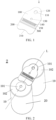
FIG. 1 is a schematic structural diagram of a busbar of an embodiment of the present disclosure. -
FIG. 2 is a schematic structural diagram of the busbar ofFIG. 1 , connected with two battery cells in series. -
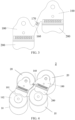
FIG. 3 is a schematic structural diagram of two busbars connected in series of an embodiment of the present disclosure. -
FIG. 4 is a schematic structural diagram of battery cells connected in parallel by the two busbars ofFIG. 3 . -
FIG. 5 is a schematic structural diagram of three busbars connected in series of an embodiment of the present disclosure. - Embodiments of the present disclosure are described in detail with the technical matters, structural features, achieved objects, and effects with reference to the accompanying drawings as follows. Specifically, the terminologies in the embodiments of the present disclosure are merely for describing the purpose of the certain embodiment, but not to limit the disclosure.
- As shown in
FIG. 1 and FIG. 2 , abusbar 1 is provided in an embodiment of the present disclosure. Thebusbar 1 is welded tobattery cells 10. Thebusbar 1 includes a first connectingportion 100 and a second connectingportion 200. The first connectingportion 100 is welded to apositive electrode 101 or anegative electrode 102 of afirst battery cell 10. The second connectingportion 200 is connected to the first connectingportion 100, and the second connectingportion 200 is welded to anegative electrode 102 or apositive electrode 101 of asecond battery cell 20. A central axis of the first connectingportion 100, a central axis of the second connectingportion 200, and a central axis of thefirst battery cell 10 and thesecond battery cell 20 connected by thebusbar 1 are coincided with each other, so as to enable series connection of thefirst battery cell 10 and thesecond battery cell 20 by thebusbar 1. - In some embodiments, the first connecting
portion 100 and the second connectingportion 200 of thebusbar 1 are of a one-piece structure. In other words, the first connectingportion 100 and the second connectingportion 200 of thebusbar 1 are integrated as a single. Thebusbar 1 can be made of aluminum alloy, so as to improve reliability of thebusbar 1 under premise of satisfying the conductivity. - The
busbar 1 can be used to connect battery cells in series or in parallel. Exemplarily, the first connectingportion 100 can be welded with thepositive electrode 101 of thefirst battery cell 10 by laser, and the second connectingportion 200 can be welded with thenegative electrode 102 of thesecond battery cell 20 by laser, so as to realize series connection of thefirst battery cell 10 and thesecond battery cell 20. - In some embodiments, the
first battery cell 10 and thesecond battery cell 20 can be cylindrical batteries. - In some embodiments, an outline dimension of the first connecting
portion 100 and an outline dimension of the second connectingportion 200 are both constant, which facilitates mass production of thebusbar 1, reduces use of different types of molds and inspection tools, and improve production efficiency. Coincidence of the central axis of the first connectingportion 100, the central axis of the second connectingportion 200, and the central axis of thefirst battery cell 10 and thesecond battery cell 20 connected by thebusbar 1 makes formation of thebusbar 1 standardized and normalized, reduces development costs of molds and inspection tools thereof, saves costs, and improves the production efficiency. It should be noted that the central axis of the first connectingportion 100 and the central axis of the second connectingportion 200 is an axis of symmetry of thebusbar 1 inFIG. 1 (not shown), and the central axis of thefirst battery cell 10 and thesecond battery cell 20 connected by thebusbar 1 is a central axis passing through positive electrodes of thefirst battery cell 10 and thesecond battery cell 20 as shown inFIG. 2 , a coincided central axis is shown as central axis L inFIG. 2 . - In this embodiment, because of the setting of the first connecting
portion 100 and the second connectingportion 200, and the coincidence of the central axis of the first connectingportion 100, the central axis of the second connectingportion 200, and the central axis of thefirst battery cell 10 and thesecond battery cell 20 connected by thebusbar 1, standardization and normalization of thebusbar 1 are realized, so as to reduce the development costs of molds and inspection tools and save costs. At the same time, it is conducive to standardized control and management of process parameters of production line of thebusbar 1, and to improve the production efficiency. - As shown in
FIG. 1 and FIG. 2 , in some embodiments, the first connectingportion 100 is provided with apositioning hole 110. Thepositioning hole 110 is located on the central axis of the first connectingportion 100 and is mounted on thepositive electrode 101 of thefirst battery cell 10. Provision of thepositioning hole 110 facilitates a laser welding device to target thebusbar 1 and improve precision of welding. Specifically, a camera on the laser welding device is able to capture thepositioning hole 110 and thus identifies a relative position of thepositioning hole 110 and thepositive electrode 101 of thefirst battery cell 10, so that a laser welding head of the laser welding device is able to weld and connect the first connectingportion 100 to thepositive electrode 101 of thefirst battery cell 10 accurately, therefore improving the precision of the welding. - Further, in some embodiments, a part of the first connecting
portion 100 located on a side thereof away from the second connectingportion 200 is protruding to define aprotrusion 120. Theprotrusion 120 is welded with thepositive electrode 101 of thefirst battery cell 10. Thepositioning hole 110 is set on theprotrusion 120. The setting of theprotrusion 120 can increase welding areas of the first connectingportion 100 and thepositive electrode 101 of thefirst battery cell 10, thereby improving reliability and stability of the welding of the first connectingportion 100 and thepositive electrode 101 of thefirst battery cell 10. - As shown in
FIG. 1 and FIG. 2 , in some embodiments, the first connectingportion 100 is further provided with afixing hole 130. Thefixing hole 130 is located on the central axis of the first connectingportion 100 and is connected to a plastic bracket (not shown). As thefixing hole 130 and thepositioning hole 110 are both located on the central axis of the first connectingportion 100, it makes the formation of thebusbar 1 standardized and normalized and improves the production efficiency. - As shown in
FIG. 1 and FIG. 2 , in some embodiments, a side surface of the second connectingportion 200 away from the first connecting portion is concave, defining anavoidance portion 210. Theavoidance portion 210 is used to avoid thepositive electrode 101 of thesecond battery cell 20 away from the first connectingportion 100, which is conducive to the welding connection between the second connectingportion 200 and thenegative electrode 102 of thesecond battery cell 20, therefore improving the stability and reliability of the welding thereof to avoid defects of false welding and bursting point. Optionally, theavoidance portion 210 is arcuate so as to make theavoidance portion 210 adapted to thepositive electrode 101 of thesecond battery cell 20. - As shown in
FIG.1 and FIG. 2 , in some embodiments, thebusbar 1 further includes acurved portion 300. An end of thecurved portion 300 is connected to the first connectingportion 100, and the other end of thecurved portion 300 is connected to the second connectingportion 200. Thearcuate protrusion 300 can provide a certain amount of deformation margin for thebusbar 1 when welding, thereby reducing stress concentration between the first connectingportion 100 and the second connectingportion 200, and improving stability and reliability of thebusbar 1. - As shown in
FIG. 1 and FIG. 2 , in some embodiments, the first connectingportion 100 or the second connectingportion 200 is provided with afirst fusing portion 140. Each of two opposite sides of thefirst fusing portion 140 is provided with a first connectingsection 150, respectively. The first connecting section is located between the first connectingportion 100 and the second connectingportion 200. In detail, an end of the first connectingsection 150 is connected to the first connectingportion 100, and the other end of the first connecting section is connected to the second connectingportion 200. - In one embodiment, the
first fusing portion 140 is connected in series to the first connectingportion 100. Thefirst fusing portion 140 is set with a fuse. Thefirst fusing portion 140 can utilize a metal conductor as its fuse. The fuse is connected in series in the first connectingportion 100. When an overload or a short circuit occurs in an entire circuit, which includes thebusbar 1, a large current is generated and passes through thefirst fusing portion 140. It will melt the fuse via heat generation therein, thus forming a protection mechanism for breaking the circuit, and preventing thefirst battery cell 10 and thesecond battery cell 20 from catching fire or even exploding because of short-circuiting. - The setting of the first connecting
sections 150 can strengthen connection strength between the first connectingportion 100 and the second connectingportion 200. In some embodiments, each first connectingsection 150 has a thin cross-section, so that after thefirst fusing portion 140 is melted, the first connectingsections 150 on the opposite sides of thefirst fusing portion 140 can also be melted. During the test, when the entire circuit is overloaded or shortcircuited, a difference in melting time between thefirst fusing portion 140 and the first connectingsection 150 is between 1 second (s) to 2s, thereby protecting thebattery cells 10 and improving safety performance of the entire circuit. - In addition, as shown in
FIG. 3 and FIG. 4 , the first connectingportion 100 can be further provided with at least one connectingarm 160. The connectingarm 160 can be provided with asecond fusing portion 170. The connectingarm 160 is provided to facilitate series connection ofadjacent busbars 1, thereby realizing parallel connection of the battery cells connected by theadjacent busbars 1. The provision of thesecond fuse portion 170 can effectively prevent thermal runaway effect of the battery cells triggered by an external short circuit. - As shown in
FIG. 3 and FIG. 4 , twoaforementioned busbars 1 can be connected. Eachbusbar 1 is provided with one connectingarm 160, connecting the first connectingportion 100. The connectingarm 160 of one of the twobusbars 1 is connected to the connectingarm 160 of the other of the twobusbars 1. An extension direction of the connectingarm 160 of one of the twobusbars 1 is different from that of the connectingarm 160 of the other of the twobusbars 1. For example, the extension directions of the connectingarms 160 are reversed. Thesecond fusing portion 170 can be provided on one of the connectingarms 160. In addition, thesecond fusing portion 170 can be located at the center of the two connectingarms 160, so as to prevent expansion force, relative displacement, or other factors generated bybattery cells 10 during charge, discharge and vibration. - As shown in
FIG. 5 , threeaforementioned busbars 1 can be connected sequentially. The threebusbars 1 includes twoend busbars 1 and acentral busbar 1. Thecentral busbar 1 is connected between the twoend busbars 1. The twoend busbars 1 can be symmetrical with respect to thecentral busbar 1. In detail, eachend busbar 1 is provided with one connectingarm 160, which is connected to the first connectingportion 100 thereof. Thecentral busbar 1 is provided with two connectingarms 160, which are symmetrical with respect to the coincided central axis of thecentral busbar 1. The connectingarm 160 of eachend busbar 1 is connected to one of the two connectingarms 160 of thecentral busbar 1. The connectingarm 160 of eachend busbar 1, or each connecting arm of thecentral busbar 1 is provided with onesecond fusing portion 170. Thesecond fusing portion 170 can be located at the center of two connected connectingarms 160, so as to prevent expansion force, relative displacement, or other factors generated bybattery cells 10 during charge, discharge and vibration. - It could be understood that the number of
busbars 1 connected can also be set as four, five and so on, so as to realize parallel connection ofbattery cells 10 on different numbers of branches in the circuit, and improve energy density of battery module. - An embodiment of the present disclosure provides a
battery module 2. Thebattery module 2 includes a plurality of battery cells and anaforementioned busbar 1. Thebusbar 1 connects the battery cells in series or in parallel. As thebattery module 2 adopts theaforementioned busbar 1, production efficiency of thebattery module 2 can be improved, thereby achieving the purpose of cost saving. - As shown in
FIG. 2 , in some embodiments, thebattery module 2 includes afirst battery cell 10, asecond battery cell 20, and abusbar 1 connected between thefirst battery cell 10 and thesecond battery cell 20 in series. - As shown in
FIG. 4 , in some embodiments, thebattery module 2 includes twobusbars 1 and two battery cell groups, each battery cell group include afirst battery cell 10 and asecond battery cell 20. Eachbusbar 1 is provided with one connectingarm 160, connecting the first connectingportion 100, and the first connectingportion 100 is welded with thepositive electrode 101 of thefirst battery cell 10 by laser, and the second connectingportion 200 is welded with thenegative electrode 102 of thesecond battery cell 20 by laser, so that thefirst battery cell 10 and thesecond battery cell 20 in the same battery cell group are connected in series through one busbar. The connectingarm 160 of one of the twobusbars 1 is connected to the connectingarm 160 of the other of the twobusbars 1, so that the two battery cell groups are connected in parallel. - An embodiment of the present disclosure provides a battery pack (not shown), including the
aforementioned battery module 2. As the production efficiency of the battery pack is high and the cost is low, the battery pack is conducive to mass production. - While the present disclosure has been described in connection with what is considered the most practical and preferred embodiments, it is understood that the present disclosure is not limited to the disclosed embodiments but is intended to cover various arrangements made without departing from the scope of the broadest interpretation of the appended claims.
Claims (11)
- A busbar (1), characterized by comprising:a first connecting portion (100), welded to a positive electrode or a negative electrode of a first battery cell (10);a second connecting portion (200), connected to the first connecting portion (100) and welded to a negative electrode or a positive electrode of a second battery cell (20), wherein a central axis of the first connecting portion (100), a central axis of the second connecting portion (200), and a central axis of the first battery cell (10) and the second battery cell (20) are coincided with each other.
- The busbar (1) of claim 1, characterized in that the first connecting portion (100) is provided with a positioning hole (110) located on the central axis of the first connecting portion (100).
- The busbar (1) of claim 1, characterized in that the first connecting portion (100) is provided with a protrusion (120) out of a side of the first connecting portion (100) away from the second connecting portion (200), and the protrusion (120) having the positioning hole (110) thereon is welded to the positive electrode of the first battery cell (10).
- The busbar (1) of claim 1, characterized in that the first connecting portion (100) is provided with a fixing hole (130) that is located on the central axis of the first connecting portion (100) and is configured to be connected to a plastic bracket.
- The busbar (1) of claim 1, characterized in that a side of the second connecting portion (200) away from the first connecting portion (100) is recessed with an avoidance portion (210) that is configured to avoid the positive electrode of the second battery cell (20).
- The busbar (1) of any one of claims 1 to 5, characterized by further comprising an curved portion (300) of which an end is connected to the first connecting portion (100), and an opposite end is connected to the second connecting portion (200).
- The busbar (1) of any one of claims 1 to 5, characterized in that the first connecting portion (100) or the second connecting portion (200) is provided with a first fusing portion (140), and each of two opposite sides of the first fusing portion (140) is provided with a first connecting section (150) located between the first connecting portion (100) and the second connecting portion (200).
- The busbar (1) of claim 7, characterized in that the first connecting portion (100) is provided with a connecting arm (160).
- The busbar (1) of claim 8, characterized in that the connecting arm (160) is provided with a second fusing portion (170).
- A battery module (2), characterized by comprising a plurality of battery cells and a busbar (1) of any one of claims 1 to 9, wherein each busbar (1) connects two battery cells in series or in parallel.
- A battery pack, characterized by comprising a battery module (2) of claim 10.
Applications Claiming Priority (2)
| Application Number | Priority Date | Filing Date | Title |
|---|---|---|---|
| CN202320636842.0U CN220604905U (en) | 2023-03-28 | 2023-03-28 | Busbar, battery module and battery pack |
| CN202310314150.9A CN116315470A (en) | 2023-03-28 | 2023-03-28 | Bus bars, battery modules and battery packs |
Publications (1)
| Publication Number | Publication Date |
|---|---|
| EP4439847A1 true EP4439847A1 (en) | 2024-10-02 |
Family
ID=89474771
Family Applications (1)
| Application Number | Title | Priority Date | Filing Date |
|---|---|---|---|
| EP23220669.8A Pending EP4439847A1 (en) | 2023-03-28 | 2023-12-29 | Busbar, battery module, and battery pack |
Country Status (3)
| Country | Link |
|---|---|
| US (1) | US20240322383A1 (en) |
| EP (1) | EP4439847A1 (en) |
| WO (1) | WO2024198025A1 (en) |
Families Citing this family (1)
| Publication number | Priority date | Publication date | Assignee | Title |
|---|---|---|---|---|
| CN113790673B (en) * | 2021-11-16 | 2022-04-01 | 江苏时代新能源科技有限公司 | A kind of battery, electric device, welding deviation detection device and method |
Citations (4)
| Publication number | Priority date | Publication date | Assignee | Title |
|---|---|---|---|---|
| JP2006261083A (en) * | 2004-09-14 | 2006-09-28 | Matsushita Electric Ind Co Ltd | Battery connection device |
| JP2022136733A (en) * | 2021-03-08 | 2022-09-21 | 三洋電機株式会社 | Battery module and battery module manufacturing method |
| CN217788723U (en) * | 2022-01-25 | 2022-11-11 | 湖北亿纬动力有限公司 | Busbar subassembly and cylinder power battery module |
| CN218351666U (en) * | 2022-10-21 | 2023-01-20 | 江苏正力新能电池技术有限公司 | Composite busbar and battery cell connecting structure |
Family Cites Families (3)
| Publication number | Priority date | Publication date | Assignee | Title |
|---|---|---|---|---|
| CN214336793U (en) * | 2021-03-31 | 2021-10-01 | 蜂巢能源科技(无锡)有限公司 | Cylindrical battery |
| CN216288839U (en) * | 2021-09-30 | 2022-04-12 | 蜂巢能源科技有限公司 | Bus bar assembly and battery module with same |
| CN218101621U (en) * | 2022-09-08 | 2022-12-20 | 中创新航科技股份有限公司 | Batteries and battery devices |
-
2023
- 2023-04-24 WO PCT/CN2023/090358 patent/WO2024198025A1/en not_active Ceased
- 2023-12-29 EP EP23220669.8A patent/EP4439847A1/en active Pending
- 2023-12-30 US US18/401,367 patent/US20240322383A1/en active Pending
Patent Citations (4)
| Publication number | Priority date | Publication date | Assignee | Title |
|---|---|---|---|---|
| JP2006261083A (en) * | 2004-09-14 | 2006-09-28 | Matsushita Electric Ind Co Ltd | Battery connection device |
| JP2022136733A (en) * | 2021-03-08 | 2022-09-21 | 三洋電機株式会社 | Battery module and battery module manufacturing method |
| CN217788723U (en) * | 2022-01-25 | 2022-11-11 | 湖北亿纬动力有限公司 | Busbar subassembly and cylinder power battery module |
| CN218351666U (en) * | 2022-10-21 | 2023-01-20 | 江苏正力新能电池技术有限公司 | Composite busbar and battery cell connecting structure |
Also Published As
| Publication number | Publication date |
|---|---|
| US20240322383A1 (en) | 2024-09-26 |
| WO2024198025A1 (en) | 2024-10-03 |
Similar Documents
| Publication | Publication Date | Title |
|---|---|---|
| CN116315470A (en) | Bus bars, battery modules and battery packs | |
| CN111952525A (en) | Homonymy mass flow device, battery module and electric motor car | |
| US12489161B2 (en) | Secondary battery and battery module | |
| CN215184417U (en) | Battery module | |
| US20240322383A1 (en) | Busbar, battery module, and battery pack | |
| WO2025091769A1 (en) | Battery cell, battery and electrical apparatus | |
| CN117878536B (en) | Connector and battery structure | |
| WO2023004766A1 (en) | Battery, electrical device and method for preparing battery | |
| WO2025010825A1 (en) | Battery cell, battery and electrical device | |
| WO2019174088A1 (en) | Battery module | |
| CN220604905U (en) | Busbar, battery module and battery pack | |
| CN219979764U (en) | Aluminum connection structure and cylindrical cell module | |
| CN222530746U (en) | Busbar and battery pack | |
| CN218548726U (en) | Battery module output electrode bus bar, battery module and battery pack | |
| CN220138643U (en) | Battery terminal and battery | |
| WO2024092731A1 (en) | End cover, battery cell, battery, and electric device | |
| CN223785273U (en) | A battery pack | |
| CN219419431U (en) | Electrode assembly, battery cell, battery and electrical device | |
| CN218677507U (en) | Battery cell fusing structure and battery module | |
| CN221978161U (en) | Internal parallel battery structure | |
| CN221486725U (en) | Box body, battery box, battery and electrical device | |
| CN224096829U (en) | Battery cells, battery packs and electrical devices | |
| CN223977979U (en) | Battery and electric equipment | |
| CN222914946U (en) | Cover plate assembly, single cell and battery | |
| CN212230561U (en) | Series-connection assembled soft-package lithium battery for electric wheelchair |
Legal Events
| Date | Code | Title | Description |
|---|---|---|---|
| PUAI | Public reference made under article 153(3) epc to a published international application that has entered the european phase |
Free format text: ORIGINAL CODE: 0009012 |
|
| STAA | Information on the status of an ep patent application or granted ep patent |
Free format text: STATUS: REQUEST FOR EXAMINATION WAS MADE |
|
| 17P | Request for examination filed |
Effective date: 20231229 |
|
| AK | Designated contracting states |
Kind code of ref document: A1 Designated state(s): AL AT BE BG CH CY CZ DE DK EE ES FI FR GB GR HR HU IE IS IT LI LT LU LV MC ME MK MT NL NO PL PT RO RS SE SI SK SM TR |
|
| STAA | Information on the status of an ep patent application or granted ep patent |
Free format text: STATUS: EXAMINATION IS IN PROGRESS |
|
| 17Q | First examination report despatched |
Effective date: 20250905 |