EP4439832A1 - Edge beam for battery tray, battery tray, battery pack, and vehicle - Google Patents
Edge beam for battery tray, battery tray, battery pack, and vehicle Download PDFInfo
- Publication number
- EP4439832A1 EP4439832A1 EP23769797.4A EP23769797A EP4439832A1 EP 4439832 A1 EP4439832 A1 EP 4439832A1 EP 23769797 A EP23769797 A EP 23769797A EP 4439832 A1 EP4439832 A1 EP 4439832A1
- Authority
- EP
- European Patent Office
- Prior art keywords
- cavity
- edge beam
- battery
- tray
- battery tray
- Prior art date
- Legal status (The legal status is an assumption and is not a legal conclusion. Google has not performed a legal analysis and makes no representation as to the accuracy of the status listed.)
- Pending
Links
Images



Classifications
-
- H—ELECTRICITY
- H01—ELECTRIC ELEMENTS
- H01M—PROCESSES OR MEANS, e.g. BATTERIES, FOR THE DIRECT CONVERSION OF CHEMICAL ENERGY INTO ELECTRICAL ENERGY
- H01M50/00—Constructional details or processes of manufacture of the non-active parts of electrochemical cells other than fuel cells, e.g. hybrid cells
- H01M50/20—Mountings; Secondary casings or frames; Racks, modules or packs; Suspension devices; Shock absorbers; Transport or carrying devices; Holders
- H01M50/233—Mountings; Secondary casings or frames; Racks, modules or packs; Suspension devices; Shock absorbers; Transport or carrying devices; Holders characterised by physical properties of casings or racks, e.g. dimensions
-
- H—ELECTRICITY
- H01—ELECTRIC ELEMENTS
- H01M—PROCESSES OR MEANS, e.g. BATTERIES, FOR THE DIRECT CONVERSION OF CHEMICAL ENERGY INTO ELECTRICAL ENERGY
- H01M50/00—Constructional details or processes of manufacture of the non-active parts of electrochemical cells other than fuel cells, e.g. hybrid cells
- H01M50/20—Mountings; Secondary casings or frames; Racks, modules or packs; Suspension devices; Shock absorbers; Transport or carrying devices; Holders
- H01M50/244—Secondary casings; Racks; Suspension devices; Carrying devices; Holders characterised by their mounting method
-
- B—PERFORMING OPERATIONS; TRANSPORTING
- B60—VEHICLES IN GENERAL
- B60L—PROPULSION OF ELECTRICALLY-PROPELLED VEHICLES; SUPPLYING ELECTRIC POWER FOR AUXILIARY EQUIPMENT OF ELECTRICALLY-PROPELLED VEHICLES; ELECTRODYNAMIC BRAKE SYSTEMS FOR VEHICLES IN GENERAL; MAGNETIC SUSPENSION OR LEVITATION FOR VEHICLES; MONITORING OPERATING VARIABLES OF ELECTRICALLY-PROPELLED VEHICLES; ELECTRIC SAFETY DEVICES FOR ELECTRICALLY-PROPELLED VEHICLES
- B60L50/00—Electric propulsion with power supplied within the vehicle
- B60L50/50—Electric propulsion with power supplied within the vehicle using propulsion power supplied by batteries or fuel cells
- B60L50/60—Electric propulsion with power supplied within the vehicle using propulsion power supplied by batteries or fuel cells using power supplied by batteries
- B60L50/64—Constructional details of batteries specially adapted for electric vehicles
-
- H—ELECTRICITY
- H01—ELECTRIC ELEMENTS
- H01M—PROCESSES OR MEANS, e.g. BATTERIES, FOR THE DIRECT CONVERSION OF CHEMICAL ENERGY INTO ELECTRICAL ENERGY
- H01M50/00—Constructional details or processes of manufacture of the non-active parts of electrochemical cells other than fuel cells, e.g. hybrid cells
- H01M50/20—Mountings; Secondary casings or frames; Racks, modules or packs; Suspension devices; Shock absorbers; Transport or carrying devices; Holders
- H01M50/233—Mountings; Secondary casings or frames; Racks, modules or packs; Suspension devices; Shock absorbers; Transport or carrying devices; Holders characterised by physical properties of casings or racks, e.g. dimensions
- H01M50/242—Mountings; Secondary casings or frames; Racks, modules or packs; Suspension devices; Shock absorbers; Transport or carrying devices; Holders characterised by physical properties of casings or racks, e.g. dimensions adapted for protecting batteries against vibrations, collision impact or swelling
-
- H—ELECTRICITY
- H01—ELECTRIC ELEMENTS
- H01M—PROCESSES OR MEANS, e.g. BATTERIES, FOR THE DIRECT CONVERSION OF CHEMICAL ENERGY INTO ELECTRICAL ENERGY
- H01M50/00—Constructional details or processes of manufacture of the non-active parts of electrochemical cells other than fuel cells, e.g. hybrid cells
- H01M50/20—Mountings; Secondary casings or frames; Racks, modules or packs; Suspension devices; Shock absorbers; Transport or carrying devices; Holders
- H01M50/249—Mountings; Secondary casings or frames; Racks, modules or packs; Suspension devices; Shock absorbers; Transport or carrying devices; Holders specially adapted for aircraft or vehicles, e.g. cars or trains
-
- H—ELECTRICITY
- H01—ELECTRIC ELEMENTS
- H01M—PROCESSES OR MEANS, e.g. BATTERIES, FOR THE DIRECT CONVERSION OF CHEMICAL ENERGY INTO ELECTRICAL ENERGY
- H01M50/00—Constructional details or processes of manufacture of the non-active parts of electrochemical cells other than fuel cells, e.g. hybrid cells
- H01M50/20—Mountings; Secondary casings or frames; Racks, modules or packs; Suspension devices; Shock absorbers; Transport or carrying devices; Holders
- H01M50/289—Mountings; Secondary casings or frames; Racks, modules or packs; Suspension devices; Shock absorbers; Transport or carrying devices; Holders characterised by spacing elements or positioning means within frames, racks or packs
-
- H—ELECTRICITY
- H01—ELECTRIC ELEMENTS
- H01M—PROCESSES OR MEANS, e.g. BATTERIES, FOR THE DIRECT CONVERSION OF CHEMICAL ENERGY INTO ELECTRICAL ENERGY
- H01M50/00—Constructional details or processes of manufacture of the non-active parts of electrochemical cells other than fuel cells, e.g. hybrid cells
- H01M50/20—Mountings; Secondary casings or frames; Racks, modules or packs; Suspension devices; Shock absorbers; Transport or carrying devices; Holders
- H01M50/289—Mountings; Secondary casings or frames; Racks, modules or packs; Suspension devices; Shock absorbers; Transport or carrying devices; Holders characterised by spacing elements or positioning means within frames, racks or packs
- H01M50/291—Mountings; Secondary casings or frames; Racks, modules or packs; Suspension devices; Shock absorbers; Transport or carrying devices; Holders characterised by spacing elements or positioning means within frames, racks or packs characterised by their shape
-
- H—ELECTRICITY
- H01—ELECTRIC ELEMENTS
- H01M—PROCESSES OR MEANS, e.g. BATTERIES, FOR THE DIRECT CONVERSION OF CHEMICAL ENERGY INTO ELECTRICAL ENERGY
- H01M2220/00—Batteries for particular applications
- H01M2220/20—Batteries in motive systems, e.g. vehicle, ship, plane
-
- H—ELECTRICITY
- H01—ELECTRIC ELEMENTS
- H01M—PROCESSES OR MEANS, e.g. BATTERIES, FOR THE DIRECT CONVERSION OF CHEMICAL ENERGY INTO ELECTRICAL ENERGY
- H01M50/00—Constructional details or processes of manufacture of the non-active parts of electrochemical cells other than fuel cells, e.g. hybrid cells
- H01M50/20—Mountings; Secondary casings or frames; Racks, modules or packs; Suspension devices; Shock absorbers; Transport or carrying devices; Holders
- H01M50/204—Racks, modules or packs for multiple batteries or multiple cells
-
- Y—GENERAL TAGGING OF NEW TECHNOLOGICAL DEVELOPMENTS; GENERAL TAGGING OF CROSS-SECTIONAL TECHNOLOGIES SPANNING OVER SEVERAL SECTIONS OF THE IPC; TECHNICAL SUBJECTS COVERED BY FORMER USPC CROSS-REFERENCE ART COLLECTIONS [XRACs] AND DIGESTS
- Y02—TECHNOLOGIES OR APPLICATIONS FOR MITIGATION OR ADAPTATION AGAINST CLIMATE CHANGE
- Y02E—REDUCTION OF GREENHOUSE GAS [GHG] EMISSIONS, RELATED TO ENERGY GENERATION, TRANSMISSION OR DISTRIBUTION
- Y02E60/00—Enabling technologies; Technologies with a potential or indirect contribution to GHG emissions mitigation
- Y02E60/10—Energy storage using batteries
Definitions
- the present disclosure relates to the field of batteries, and specifically to an edge beam for a battery tray, a battery tray, a battery pack and a vehicle.
- a battery pack is provided with a battery tray.
- the battery tray includes a frame, and the frame includes an edge beam.
- the edge beam has insufficient structural strength and poor stability, so that the edge beam tends to deform, affecting the service life of the edge beam.
- the impact force transmitted to the inside of the battery pack is large, and a battery core in the battery pack has a high risk of damage, affecting the safety of the battery pack during use.
- an object of the present disclosure is to provide an edge beam for a battery tray.
- the structural strength and rigidity of the edge beam is increased, the battery pack is ensured to have an appropriate modal, the impact force is absorbed when the sub-cavity is impacted, and the impact force transmitted to the inside of the battery pack is reduced, thereby improving the safety of the battery pack during use, reducing the risk of deformation of the edge beam, and extending the service life of the edge beam and the battery tray.
- the present disclosure further provides a battery tray.
- the present disclosure further provides a battery pack.
- the present disclosure further provides a vehicle.
- the battery tray has a placing slot for accommodating a battery core.
- the edge beam includes: an edge beam body.
- the edge beam body defines a cavity, and the edge beam body has a partition portion.
- the partition portion is located in the cavity, and the partition portion is connected between a top wall and a bottom wall of the cavity to divide the cavity into a first sub-cavity and a second sub-cavity.
- the first sub-cavity and the second sub-cavity are arranged in a first direction of the edge beam in sequence.
- the first sub-cavity has a cross-sectional area of S 1
- the second sub-cavity has a cross-sectional area of S2
- S1 and S2 meet the relation formula: 0.8 ⁇ S1/S2 ⁇ 1 .
- the structural strength and rigidity of the edge beam is increased, the battery pack is ensured to have an appropriate modal, the risk of deformation of the edge beam is reduced, to extend the service life of the edge beam and the battery tray, and the battery pack has a high impact protection capability while the battery pack is ensured to have an appropriate modal.
- the first sub-cavity in a first direction of the edge beam, is located between the second sub-cavity and the placing slot.
- the partition portion is obliquely connected between the top wall and the bottom wall of the cavity.
- the partition portion in a direction from an upper end to a lower end of the edge beam, is arranged to tilt away from the placing slot.
- the cross-sectional shape of the first sub-cavity and the cross-sectional shape of the second sub-cavity are both triangular or trapezoidal.
- the edge beam is configured as an integrally formed component.
- the cavity in a width direction of the edge beam, has a first side wall arranged away from the placing slot.
- the first side wall is connected between the top wall and the bottom wall of the cavity, and the first side wall is connected to the partition portion.
- a lower end of the first side wall is connected with a first connecting portion extending toward the interior of the cavity.
- the first connecting portion is located at a side of the bottom wall of the cavity facing the top wall of the cavity, the first side wall is connected to the bottom wall of the cavity and the partition portion through the first connecting portion, and the first connecting portion is fixedly connected to the bottom wall of the cavity.
- the cavity has a second side wall close to the placing slot.
- the second side wall is connected between the top wall and the bottom wall of the cavity, and the second side wall is connected to the partition portion.
- an upper end of the second side wall is connected with a second connecting portion extending toward the interior of the cavity.
- the second connecting portion is located at a side of the top wall of the cavity facing the bottom wall of the cavity, the second side wall is connected to the top wall of the cavity and the partition portion through the second connecting portion, and the second connecting portion is fixedly connected to the top wall of the cavity.
- the edge beam further includes a supporting portion.
- the supporting portion is provided at a side of the edge beam body close to the placing slot, and the supporting portion is configured to support the battery core.
- a lower end of the second side wall is connected with the supporting portion extending toward the placing slot, and the second side wall is connected to the bottom wall of the cavity through the supporting portion.
- the second side wall is obliquely connected between the top wall and the bottom wall of the cavity, and in the direction from the upper end to the lower end of the edge beam, the second side wall is arranged to tilt toward the placing slot.
- the bottom wall of the cavity in the width direction of the edge beam, has a structure strengthening portion extending below the supporting portion, and the structure strengthening portion is connected to an end portion of the supporting portion close to the placing slot.
- the structure strengthening portion is provided with a boss protruding toward the supporting portion, and the boss is connected to the supporting portion.
- the cavity in the width direction of the edge beam, has a first side wall arranged away from the placing slot.
- the first side wall is connected between the top wall and the bottom wall of the cavity.
- the cavity has a second side wall close to the placing slot.
- the second side wall is connected between the top wall and the bottom wall of the cavity.
- the top wall of the cavity, the bottom wall of cavity, the first side wall and the second side wall define the cavity together, and the bottom wall of the cavity extends toward the placing slot to form the supporting portion configured to support the battery core.
- the battery tray according to the present disclosure includes the edge beam for a battery tray as described above.
- the battery tray according to the present disclosure includes: a tray bottom plate, where the tray bottom plate includes a bottom plate body and an extension portion, in which the bottom plate body defines a placing slot for accommodating a battery core, and the extension portion extends along a peripheral edge of the bottom plate body; and a frame, where the frame includes a side beam, a front beam and a rear beam.
- the side beam is the edge beam.
- the side beam, the front beam and the rear beam are connected to form a mounting space, and the bottom plate body is mounted in the mounting space.
- the extension portion is located above the frame and arranged on the frame. At least one of the side beam, the front beam and the rear beam has a supporting portion extending toward the mounting space and the supporting portion is configured to support the tray bottom plate.
- the battery pack according to the present disclosure includes: a battery core; a battery tray, where the battery tray is a battery tray as described above, the battery tray has a placing slot, and the battery core is accommodated in the placing slot.
- the vehicle according to the present disclosure includes a battery pack as described above.
- An edge beam 23 for a battery tray 100 will be described below with reference to FIGs. 1 to 13 .
- Multiple edge beams 23 are connected into a frame 20 of the battery tray 100, and the frame 20 defines a mounting space 21.
- the battery tray 100 is applied to a battery pack 200, and the battery tray 100 has a tray bottom plate 10 for supporting a battery core 201.
- the edge beam 23 is connected to the tray bottom plate 10.
- the battery tray 100 has a placing slot 111 for accommodating the battery core 201.
- the edge beam 23 includes an edge beam body 231.
- the edge beam body 231 defines a cavity 2311, and the edge beam body 231 has a partition portion 232.
- the partition portion 232 is located in the cavity, and the partition portion 232 is connected between a top wall 233 of the cavity 2311 and a bottom wall 234 of the cavity 2311.
- the partition portion 232 divides the cavity 2311 into a first sub-cavity 2351 and a second sub-cavity 2352.
- the first sub-cavity 2351 and the second sub-cavity 2352 are arranged in a first direction of the edge beam 23 in sequence.
- the first direction of the edge beam 23 refers to a width direction of the edge beam 23, a width direction of the battery tray 100, or a length direction of the battery tray 100.
- the width direction of the edge beam 23 refers to a left-right direction as shown in FIG. 11 .
- the partition portion 232 can divide the 2311 cavity into multiple sub-cavities 235 when connected between the top wall 233 of the cavity 2311 and the bottom wall 234 of the cavity 2311.
- the partition portion 232 divides the cavity 2311 into two sub-cavities 235, the two sub-cavities 235 are respectively the first sub-cavity 2351 and the second sub-cavity 2352.
- the partition portion 232 divides the cavity 2311 into four sub-cavities 235
- the four sub-cavities 235 are arranged in the first direction of the edge beam 23 in sequence.
- Two adjacent sub-cavities 235 form the first sub-cavity 2351
- the other two adjacent sub-cavities 235 form the second sub-cavity 2352.
- the partition portion 232 divides the cavity 2311 into six sub-cavities 235
- the six sub-cavities 235 are arranged in the first direction of the edge beam 23 in sequence.
- Three adjacent sub-cavities 235 form the first sub-cavity 2351
- the other three adjacent sub-cavities 235 form the second sub-cavity 2352, and so on.
- the present disclosure will be described by way of example in which the partition portion 232 divides the cavity 2311 into two sub-cavities 235.
- the first sub-cavity 2351 has a cross-sectional area of S1
- the second sub-cavity 2352 has a cross-sectional area of S2
- S1 and S2 meet the relation formula: 0.8 ⁇ S1/S2 ⁇ 1, further, 0.8 ⁇ S1/S2 ⁇ 0.99.
- the cross-sectional area of the first sub-cavity 2351 refers to the cross-sectional area in the width direction of the edge beam 23, that is, the area of a cross section of the first sub-cavity 2351 that is perpendicular to a length direction of the edge beam 23.
- the cross-sectional area of the second sub-cavity 2352 refers to the cross-sectional area in the width direction of the edge beam 23, that is, the area of a cross section of the second sub-cavity 2352 that is perpendicular to a length direction of the edge beam 23.
- the impacted sub-cavity 235 can absorb the impact force, which reduces the impact force transmitted to the inside of the battery pack 200, and reduces the risk of damage of the battery core 201 in the battery pack 200, thus improving the safety of the battery pack 200 during use.
- the partition portion 232 is obliquely connected between the top wall 233 of the cavity 2311 and the bottom wall 234 of the cavity 2311.
- the partition portion 232 By obliquely connecting the partition portion 232 between the top wall 233 of the cavity 2311 and the bottom wall 234 of the cavity 2311, the partition portion 232 is reliably supported between the top wall 233 of the cavity 2311 and the bottom wall 234 of the cavity 2311, whereby the structural strength and rigidity of the edge beam body 231 are increased, the structural stability of the edge beam body 231 is increased, and the risk of deformation of the edge beam 23 is reduced, to extend the service life of the edge beam 23 and the battery tray 100.
- the first sub-cavity 2351 is located between the second sub-cavity 2352 and the placing slot 111, or it can be considered that the first sub-cavity 2351 is located between the second sub-cavity 2352 and the mounting space 21 of the battery tray 100.
- the edge beam 23 is arranged in a pattern as shown in FIG. 12 , the placing slot 111 is left to the edge beam 23, the sub-cavity 235 on the left side is the first sub-cavity 2351, and the sub-cavity 235 on the right side is the second sub-cavity 2352.
- the impacted second sub-cavity 2352 can absorb the impact force, which reduces the impact force transmitted to the inside of the battery pack 200, and reduces the risk of damage of the battery core 201 in the battery pack 200, thus improving the safety of the battery pack 200 during use.
- the cross-sectional area of the sub-cavity 235 close to the placing slot 111 has a great influence on the modal of the battery pack 200, that is, the cross-sectional area of the first sub-cavity 2351 has a great influence on the modal of the battery pack 200.
- the cross-sectional area S1 of the first sub-cavity 2351 increases, the rigidity of the battery pack 200 becomes worse, the modal of the battery pack 200 declines, and the probability of resonance of the battery pack 200 increases.
- the cross-sectional area of the sub-cavity 235 away from the placing slot 111 has a great influence on the impact protection of the vehicle, that is, the cross-sectional area of the second sub-cavity 2352 has a great influence on the impact protection of the vehicle.
- the cross-sectional area S2 of the second sub-cavity 2352 increases, the pressurized area of the second sub-cavity 2352 becomes smaller, the energy that the edge beam 23 can absorb upon collision of the vehicle with an external force becomes smaller, and the collision safety risk rises.
- the battery pack 200 when 0.8 ⁇ S1/S2 ⁇ 1, the battery pack 200 is ensured to have an appropriate modal, the probability of resonance of the battery pack 200 can be reduced, and the battery pack 200 can have a high impact protection capability while the battery pack 200 is ensured to have an appropriate modal, so that the battery pack 200 can achieve a balance between the modal of the whole pack and the impact protection of the vehicle.
- the partition portion 232 when the edge beam 23 is arranged in a pattern as shown in FIG. 11 , in a direction from an upper end to a lower end of the edge beam 23, the partition portion 232 is arranged to tilt away from the placing slot 111, or it can be considered that the partition portion 232 is arranged to tilt away from the mounting space 21 of the battery tray 100, or it can be considered that in an up-down direction of the battery tray 100, the partition portion 232 is arranged to extend obliquely away from the placing slot 111.
- the partition portion 232 divides the cavity 2311 into the first sub-cavity 2351 and the second sub-cavity 2352.
- the partition portion 232 is vertically connected between the top wall 233 of the cavity 2311 and the bottom wall 234 of the cavity 2311.
- the partition portion 232 is more reliably supported between the top wall 233 of the cavity 2311 and the bottom wall 234 of the cavity 2311, the structural strength of the edge beam 23 is increased, and the stability of the edge beam 23 is improved, thereby improving the capability of the edge beam 23 to support the battery core 201, and further reducing the risk of deformation of the frame 20.
- the cross-sectional shape of the first sub-cavity 2351 and the cross-sectional shape of the second sub-cavity 2352 are both triangular or trapezoidal.
- the first sub-cavity 2351 is located at a side of the second sub-cavity 2352 close to the mounting space 21.
- the cross-sectional shape of the first sub-cavity 2351 is triangular, and further, isosceles triangle or equilateral triangle.
- the bottom wall 234 of the cavity 2311 serves as a bottom wall of the triangle.
- the angle between the bottom wall 234 of the cavity 2311 and the partition portion 232 serves as a base angle of the triangle.
- the base angle is ⁇ 1 that meets the relation formula: 50° ⁇ 1 ⁇ 70°.
- ⁇ 1 is 60°.
- the vertex angle of the triangle is ⁇ 1 that meets the relation formula: 50° ⁇ 1 ⁇ 70°.
- ⁇ 1 is 60°.
- the cross-sectional shape of the first sub-cavity 2351 is arranged to be an equilateral triangle. Through such an arrangement, the structural stability of the edge beam 23 is further increased, and the risk of deformation of the edge beam 23 is further reduced, thereby further extending the service life of the edge beam 23 and the battery tray 100.
- the first sub-cavity 2351 is located at a side of the second sub-cavity 2352 close to the placing slot 111.
- the cross-sectional shape of the first sub-cavity 2351 is arranged to be a trapezoid.
- the bottom wall 234 of the cavity 2311 serves as a bottom wall of the trapezoid.
- the angle between the bottom wall 234 of the cavity 2311 and the partition portion 232 serves as a base angle of the trapezoidal shape of the first sub-cavity 2351.
- the base angle is ⁇ 2 that meets the relation formula: 50° ⁇ 2 ⁇ 70°. For example, ⁇ 2 is 60°.
- the angle between the two waists of the trapezoidal shape of the first sub-cavity 2351 is ⁇ 2 that meets the relation formula: 50° ⁇ 2 ⁇ 70°.
- ⁇ 2 is 60°.
- the cross-sectional shape of the second sub-cavity 2352 is arranged to be a trapezoid.
- the bottom wall 234 of the cavity 2311 serves as a top wall of the trapezoidal shape of the second sub-cavity 2352
- the top wall 233 of the cavity 2311 serves as a bottom wall of the trapezoidal shape of the second sub-cavity 2352.
- the edge beam body 231 also has a supporting portion 22 extending toward the placing slot 111 of the battery tray 100.
- the supporting portion 22 is located below the tray bottom plate 10, and the supporting portion 22 is configured to support the battery core 201 in the tray bottom plate 10.
- the edge beam 23 mainly bears the weight of the battery core 201.
- the tray bottom plate 10 of the battery tray 100 bears a small fraction of the weight of the battery core 201, greatly reducing the weight bearing requirement for the tray bottom plate 10.
- the edge beam 23 is configured as an integrally formed component.
- the edge beam 23 can be formed of an aluminum material, or the edge beam 23 can be formed of a steel material, which is not limited in the present disclosure.
- the edge beam 23 can also be made of other metal materials that have the same function as steel.
- the edge beam 23 is made of a steel material.
- the edge beam 23 can be rolled with the steel material, or the edge beam 23 can also be extruded with the steel material.
- the edge beam 23 made of a steel material can withstand a high temperature of 1500°C more, which ensures the integrity of the edge beam 23 upon thermal runaway of the battery core 201.
- the cavity 2311 has a first side wall 236 arranged away from the placing slot 111.
- the first side wall 236 is connected between the top wall 233 of the cavity 2311 and the bottom wall 234 of the cavity 2311, and the first side wall 236 is connected to the partition portion 232.
- a lower end of the first side wall 236 is connected with a first connecting portion 238 extending toward the interior of the cavity 2311.
- the first connecting portion 238 is located at a side of the bottom wall 234 of the cavity 2311 facing the top wall 233 of the cavity 2311, the first side wall 236 is connected to the bottom wall 234 of the cavity 2311 and the partition portion 232 through the first connecting portion 238, and the first connecting portion 238 is fixedly connected to the bottom wall 234 of the cavity 2311.
- the first connecting portion 238 is welded to the bottom wall 234 of the cavity 2311.
- the cavity 2311 in the width direction of the edge beam 23, has a second side wall 237 close to the placing slot 111.
- the second side wall 237 is connected between the top wall 233 of the cavity 2311 and the bottom wall 234 of the cavity 2311, and the second side wall 237 is connected to the partition portion 232.
- an upper end of the second side wall 237 is connected with a second connecting portion 239 extending toward the interior of the cavity 2311.
- the second connecting portion 239 is located at a side of the top wall 233 of the cavity 2311 facing the bottom wall 234 of the cavity 2311, the second side wall 237 is connected to the top wall 233 of the cavity 2311 and the partition portion 232 through the second connecting portion 239, and the second connecting portion 239 is fixedly connected to the top wall 233 of the cavity 2311.
- the second connecting portion 239 is welded to the top wall 233 of the cavity 2311.
- the top wall 233 of the cavity 2311, the bottom wall 234 of the cavity 2311, the first side wall 236 and the second side wall 237 define the cavity 2311 together.
- the edge beam 23 includes a supporting portion 22.
- the supporting portion 22 is provided at a side of the edge beam body 231 close to the placing slot 111, and the supporting portion 22 is configured to support the battery core 201. That is, the edge beam body 231 is connected with the supporting portion 22 extending toward the placing slot 111.
- the supporting portion 22 is configured to support the battery core 201 in the tray bottom plate 10 of the battery tray 100.
- the supporting portion 22 supports a lower surface of the tray bottom plate 10 to support the battery core 201.
- the edge beam 23 bears most of the weight of the battery core 201.
- the tray bottom plate 10 of the battery tray 100 does not bear the weight of the battery core 201 or only bears a small fraction of the weight of the battery core 201, greatly reducing the weight bearing requirement for the tray bottom plate 10.
- a lower end of the second side wall 237 is connected with the supporting portion 22 extending toward placing slot 111, the supporting portion 22 can be configured to support the tray bottom plate 10, and the second side wall 237 is connected to the bottom wall 234 of the cavity 2311 through the supporting portion 22.
- the bottom wall 234 of the cavity 2311 has a structure strengthening portion 2341 extending below the supporting portion 22.
- the structure strengthening portion 2341 is connected to an end portion of the supporting portion 22 close to the tray bottom plate 10, or it can be considered that the structure strengthening portion 2341 extends below the supporting portion 22, and an end portion of the bottom wall 234 of the cavity 2311 close to the placing slot 111 is connected to an end portion of the structure strengthening portion 2341 close to the placing slot 111. Further, the structure strengthening portion 2341 is provided with a boss (that is, boss structure 2391) protruding toward the supporting portion 22, and the boss structure 2391 is connected to the supporting portion 22. Through such an arrangement, the structural strength of the edge beam 23 is further increased, and the stability of the edge beam 23 is further improved.
- the structure strengthening portion 2341 is provided with multiple boss structures 2391.
- the multiple boss structures 2391 are arranged in the width direction of the edge beam 23 in sequence. At least one boss structure 2391 of the multiple boss structures 2391 is located below the battery core 201. Such an arrangement enables the boss structure 2391 to support the battery core 201, thereby further improving the weight bearing capacity of the frame 20 and reducing the risk of deformation of the supporting portion 22.
- the cavity 2311 in the width direction of the edge beam 23, has a first side wall 236 arranged away from the placing slot 111.
- the first side wall 236 is connected between the top wall 233 of the cavity 2311 and the bottom wall 234 of the cavity 2311.
- the cavity 2311 has a second side wall 237 close to the placing slot 111.
- the second side wall 237 is connected between the top wall 233 of the cavity 2311 and the bottom wall 234 of the cavity 2311.
- the top wall 233 of the cavity 2311, the bottom wall 234 of the cavity 2311, the first side wall 236 and the second side wall 237 define the cavity 2311 together.
- the bottom wall 234 of the cavity 2311 extends toward the placing slot 111 to form the supporting portion 22 configured to support the tray bottom plate 10.
- the supporting portion 22 is located below the tray bottom plate 10, and the supporting portion 22 extends to a position below the battery core 201. Such an arrangement enables the supporting portion 22 to support the battery core 201, thereby further improving the weight bearing capacity of the edge beam 23.
- the second side wall 237 is obliquely connected between the top wall 233 of the cavity 2311 and the bottom wall 234 of the cavity 2311.
- the second side wall 237 is arranged to tilt toward the placing slot 111.
- the battery tray 100 includes: a tray bottom plate 10 (the tray bottom plate 10 according to the above embodiment) and a frame 20 (the frame 20 according to the above embodiment).
- the tray bottom plate 10 includes a bottom plate body 11 and an extension portion 12.
- the bottom plate body 11 defines a placing slot 111 for accommodating a battery core 201 or a battery module.
- the placing slot 111 accommodates the battery core 201.
- the battery core 201 can be bonded in the placing slot 111 by a structural adhesive.
- the placing slot 111 has a bottom wall 113 of the placing slot.
- the bottom wall 113 of the placing slot has a pressurized area 112 for supporting the battery core 201.
- the pressurized area 112 refers to an area where the orthographic projection of the bottom wall 113 of the placing slot overlaps with the orthographic projection of the battery core 201 in a height direction of the battery tray 100, when the battery core 201 is mounted in the placing slot 111. Alternatively, it can be considered as a contact area between the battery core 201 and the bottom wall 113 of the placing slot when the battery core 201 is mounted in the placing slot 111.
- the contact area includes an area where the battery core 201 is in direct contact or indirect contact with the bottom wall 113 of the placing slot.
- the battery core 201 is in indirect contact with the bottom wall 113 of the placing slot when there is an adhesive or a cooling structure between the battery core 201 and the bottom wall 113 of the placing slot, and the battery core 201 is in direct contact with the bottom wall 113 of the placing slot when there is no an additional object between the battery core 201 and the bottom wall 113 of the placing slot.
- an area where the weight of the battery core 201 directly acts on the bottom wall 113 of the placing slot is the pressurized area 112.
- the orthogonal projection of the bottom wall 113 of the placing slot is also the projection of the bottom wall 113 of placing slot to a plane perpendicular to the height direction of the battery tray 100.
- the orthogonal projection of the battery core 201 is the projection of the battery core 201 in a plane perpendicular to the height direction of the battery tray 100.
- the extension portion 12 is arranged to extend along a peripheral edge of the bottom plate body 11. Further, the extension portion 12 is configured as a loop structure. Particularly, the extension portion 12 is configured as a closed-loop structure.
- the frame 20 defines the mounting space 21, and the bottom plate body 11 is mounted to the frame 20. Further, the bottom plate body 11 is fixedly mounted to the frame 20. The bottom plate body 11 may be bonded to the frame 20, or the bottom plate body 11 may be connected to the frame 20 by a bolt.
- the specific assembly method of the bottom plate body 11 and the frame 20 is not specifically limited, and can be selected according to actual needs.
- the bottom plate body 11 is mounted in the mounting space 21, and the extension portion 12 is located outside the mounting space 21. In the height direction of the battery tray 100, the extension portion 12 is located above the frame 20 and arranged on the frame 20.
- the frame 20 includes a side beam, a front beam 24 and a rear beam 25. At least one of the side beam, the front beam 24 and the rear beam 25 is the edge beam 23 according to the above embodiment.
- the edge beam 23, the front beam 24 and the rear beam 25 are connected to define the mounting space 21.
- the connection of the side beam, the front beam 24 and the rear beam 25 includes direct connection and indirect connection.
- the side beam and the front beam 24 can be directly connected, or the side beam and the front beam 24 can also be indirectly connected by an additional beam.
- the side beam and/or the front beam 24 and/or the rear beam 25 has the supporting portion 22 extending toward the mounting space 21, or it can be considered that at least one of the side beam, the front beam 24 and the rear beam 25 has the supporting portion 22 extending toward the mounting space 21.
- the supporting portion 22 is configured to support the tray bottom plate 10.
- Two side beams, one rear beam 25 and one front beam 24 are provided. When the frame 20 is arranged in a pattern as shown in FIG. 8 , the two side beams are spaced away in the left-right direction in FIG. 8 , and the front beam 24 and the rear beam 25 are connected between the two side beams. The front beam 24 and the rear beam 25 are spaced away in the front-rear direction of the frame 20.
- the front beam 24, the rear beam 25 and the two side beams jointly define the mounting space 21.
- the battery core 201 is arranged to extend in the left-right direction as shown in FIG. 8 , by arranging the supporting portion 22 on the side beam, each battery core 201 is ensured to be supported by the supporting portion 22, which can further ensure that the supporting portion 22 supports the battery core 201, and further ensure that the frame 20 is mainly used for bearing the weight of the battery core 201. Consequently, the arrangement of the position of the supporting portion 22 is reasonable.
- the width direction of the battery tray 100 may be consistent with the width direction of the vehicle, and the length direction of the battery tray 100 may be consistent with the length direction of the vehicle.
- the width direction of the battery tray 100 may be consistent with the length direction of the vehicle, and the length direction of the battery tray 100 may be consistent with the width direction of the vehicle.
- the supporting portion 22 is configured to support the pressurized area 112 of the tray bottom plate 10.
- the battery tray 100 is arranged in an up-down direction in the present disclosure.
- the extension portion 12 is arranged outside the mounting space 21.
- the extension portion 12 is arranged corresponding to the frame 20.
- the extension portion 12 is located above the frame 20, and the extension portion 12 is arranged to direct face the frame 20.
- the extension portion 12 covers the entire upper surface of the frame 20.
- the tray bottom plate 10 can be made of materials with lower strength and small thickness.
- the tray bottom plate 10 is configured as a nonmetallic member. In some optional embodiments, the tray bottom plate 10 is configured as an insulating member.
- the tray bottom plate 10 may be formed of a lightweight nonmetallic composite material.
- the lightweight nonmetallic composite material can be made of a resin and glass fiber, where the resin can be epoxy resin or polyurethane, which is not limited in the present disclosure.
- the lightweight composite material can also be a composite material that is made of other resins and glass fiber and has the same function. Such an arrangement can reduce the weight of the tray bottom plate 10, which is beneficial to the lightweight design of the battery tray 100 and the battery pack 200.
- the existing tray bottom plate 10 is made of an aluminum material.
- the tray bottom plate 10 is formed of a nonmetallic composite material, which reduces the production cost of the tray bottom plate 10, and facilitates the reduction of the production cost of the battery tray 100 and the battery pack 200. It is to be understood that the tray bottom plate 10 formed of a nonmetallic composite material has excellent electrical insulation performance. When a serious bottom scratching accident occurs to the vehicle 2000, the battery pack 200 will not have the risks such as high-voltage arcing.
- the tray bottom plate 10 is configured as an integrally formed component.
- the tray bottom plate 10 is molded with a lightweight nonmetallic composite material. During the molding process, the tray bottom plate 10 has good air tightness formed after the resin is melted to flow and then solidified, and the tray bottom plate 10 is ensured to have good flatness and dimensional accuracy by molding, thus ensuring the sealing function of the tray bottom plate 10.
- the frame 20 can be formed by tailor-welding with a metal. After tailor-welding, the strength of the welded structure and necessary flatness of the product need to be ensured. The tailor-welding efficiency is high, which improves the production efficiency of the battery tray 100.
- the tray bottom plate 10 is responsible for sealing; and there is no need for weld grinding and air tightness testing, and no risk of sealing failure caused by welding.
- the tray bottom plate 10 can be formed by molding with a composite material.
- the tray bottom plate 10 has high production efficiency, and the precision of the mold is high, so a high flatness can be attained. Accordingly, the size requirement for the battery core 201 is reduced.
- the existing battery tray 100 does not divide the product structure with respect to the functions of weight bearing and sealing.
- both the overall weight bearing capacity and the sealing performance need to meet the requirements, resulting in low manufacturing efficiency and yield of the battery tray 100.
- the functions of weight bearing and sealing are divided.
- the frame 20 is mainly responsible for weight bearing, and the tray bottom plate 10 is mainly responsible for sealing. These improve the manufacturing efficiency and yield of the battery tray 100.
- the tray bottom plate 10 and the frame 20 where the frame 20 mainly bears the weight of the battery core 201 and the tray bottom plate 10 bears only a small fraction of the weight of the battery core 201; and the tray bottom plate 10 is mainly responsible for sealing, the thickness of the tray bottom plate 10 is reduced, and the tray bottom plate 10 can be formed of a lightweight composite material, which is beneficial to the lightweight design and reduction of the production cost of the battery tray 100 and the battery pack 200.
- the tray bottom plate 10 and the frame 20 are in sealed connection.
- the frame 20 is provided with multiple bolt holes 28, the extension portion 12 is provided with multiple avoidance through holes 122, and the multiple bolt holes 28 are arranged in one-to-one correspondence with the multiple avoidance through holes 122.
- Multiple rivet nuts are embedded in the frame 20, and the multiple rivet nuts are arranged in one-to-one correspondence with the multiple bolt holes 28.
- the rivet nut extends through the escape through hole 122 and the bolt hole 28.
- the battery pack 200 includes a cover 40, the cover 40 and the tray bottom plate 10 jointly define an accommodating cavity 41 for accommodating the battery core 201, and the cover 40 is connected to the frame 20. Further, the cover 40 is covered at an open end of the placing slot 111 to define the accommodating cavity 41.
- the extension portion 12 is sandwiched between the cover 40 and the frame 20.
- the bolt extends through the cover 40, the avoidance through hole 122 of the extension portion 12 and the bolt hole 28 of the frame 20, and is connected to the rivet nut, whereby the cover 40, the tray bottom plate 10 and the frame 20 are assembled together.
- sealing is formed between the bolt and the bolt hole 28, so that the leak-tightness of the battery tray 100 is improved, the water vapor can be prevented from flowing into the placing slot 111 through the bolt hole 28 on the frame 20, and the battery pack 200 can also be prevented from being short-circuited, thereby improving the safety of the battery pack 200 during use.
- the tray bottom plate 10 and the frame 20 are sealed connected by a sealing structure 13.
- the sealing structure 13 is configured as a sealant, and the sealing structure 13 may also be configured as a rubber member, which is not limited in the present disclosure.
- the sealing structure 13 can also be configured as a seal having the same function as the sealant.
- the sealing structure 13 can be sandwiched in the whole space between the tray bottom plate 10 and the frame 20, or the sealing structure 13 can be sandwiched in part of the space between the tray bottom plate 10 and the frame 20.
- the sealing structure 13 can be arranged to surround the bolt hole 28 and the avoidance through hole 122. Further, the sealing structure 13 can extend into the bolt hole 28 and the avoidance through hole 122.
- the sealing structure 13 is provided between the extension portion 12 and the frame 20. Since the avoidance through hole 122 is provided in the extension portion 12, by providing the sealing structure 13 between the extension portion 12 and the frame 20, the sealing structure 13 can seal the bolt hole 28 and the avoidance through hole 122, making the arrangement of the position of the sealing structure 13 reasonable.
- the orthographic projection of the supporting portion 22 and the orthographic projection of the pressurized area 112 have an overlapping area.
- the battery core 201 is accommodated in the placing slot 111, such an arrangement can ensure that the supporting portion 22 supports the battery core 201, and ensure that the frame 20 is mainly used for bearing the weight of the battery core 201.
- the bottom wall 113 of the placing slot 111 is formed with a pressurized area 112.
- the pressurized area 112 is provided on the bottom wall 113 of the placing slot 111.
- FIG. 11 when the battery tray 100 is arranged in a pattern as shown in FIG. 11 , the supporting portion 22 is located below the bottom plate body 11, and the supporting portion 22 supports the bottom wall 113. This arrangement ensures that the supporting portion 22 is located below and support the pressurized area 112, which can further ensure that the supporting portion 22 supports the battery core 201, and further ensure that the frame 20 is mainly used for bearing the weight of the battery core 201. Consequently, the arrangement of the position of the pressurized area 112 is reasonable.
- the frame 20 further includes a supporting beam 26.
- the supporting beam 26 is connected between two edge beams 23, the supporting beam 26 is connected between the front beam 24 and the rear beam 25, the supporting beam 26 is connected between the front beam 24 and the edge beam 23, or the supporting beam 26 is connected between the rear beam 25 and the edge beam 23.
- This arrangement can improve the structural strength of the frame 20 and thus the structural strength of the battery tray 100.
- the battery tray 100 further includes an expansion beam 27.
- the expansion beam 27 is provided on a side of the tray bottom plate 10 away from the frame 20.
- the expansion beam 27 is provided above the tray bottom plate 10, and the expansion beam 27 is mounted on the support beam 26 by a bolt. After the battery core 201 is mounted in the placing slot 111, when the battery core 201 expands, the expansion beam 27 restrains the battery core 201, to improve the safety of the battery core 201 during use.
- multiple supporting beams 26 are provided.
- the multiple supporting beams 26 are spaced away in sequence in a length direction of the edge beam 23.
- the length direction of the edge beam 23 refers to the front-rear direction in FIG. 6 .
- Multiple expansion beams 27 are provided, and the multiple expansion beams 27 are spaced away in sequence in the length direction of the edge beam 23.
- the multiple expansion beams 27 and the multiple supporting beams 26 are arranged in one-to-one correspondence, and one expansion beam 27 is mounted on one supporting beam 26 by a bolt, to stably mount the expansion beam 27 on the frame 20.
- the supporting portion 22 is provided close to the lower end of the edge beam 23.
- the supporting portion 22 is provided close to an end portion of the edge beam 23 away from the tray bottom plate 10.
- the upper end of the placing slot 111 is arranged to be open, and the battery core 201 can be placed in the placing slot 111 through the open end of the placing slot 111.
- the extension portion 12 is arranged to extend along a peripheral edge at the open end of the placing slot 111. As shown in FIG. 11 , the extension portion 12 is connected to an upper end of the bottom plate body 11.
- a surface of the supporting portion 22 close to the tray bottom plate 10 is configured as a planar surface. That is to say, as shown in FIG. 11 , the upper surface of the supporting portion 22 is a planar surface, and such an arrangement can ensure the supporting area between the supporting portion 22 and the bottom plate body 11 and allows the supporting portion 22 to well support the battery core 201.
- the supporting portion 22 is located below the bottom plate body 11 and fixedly connected to the bottom plate body 11.
- the tray bottom plate 10 is bonded to the frame 20. Further, the supporting portion 22 and the bottom plate body 11 are bonded by applying an adhesive (such as structural adhesive) between the tray bottom plate 10 and the frame 20.
- an adhesive such as structural adhesive
- the dimensional tolerance of the frame 20 is absorbed by controlling the thickness of the adhesive.
- the tray bottom plate 10 has good flatness, and the manufacturing requirements for the tray bottom plate 10 and the frame 20 are reduced by taking advantage of the characteristic that the adhesive can absorb the tolerance.
- the tray bottom plate 10 tend to deform during the welding process, which increases the size requirements for the battery core 201 in the subsequent assembly process of the battery pack 200, and affects the assembly efficiency of the battery pack 200.
- the tray bottom plate 10 and the frame 20 are bonded to avoid the welded connection of the tray bottom plate 10 and the frame 20. This can prevent the deformation of the tray bottom plate 10, reduce the size requirements for the battery core 201 in the subsequent assembly process of the battery pack 200, and improve the assembly efficiency of the battery pack 200.
- the tray bottom plate 10 is configured as an integrally formed component.
- the tray bottom plate 10 is molded with a lightweight composite material. During the molding process, the tray bottom plate 10 has good air tightness formed after the resin is melted to flow and then solidified, and the tray bottom plate 10 is ensured to have good flatness and dimensional accuracy by molding, thus ensuring the sealing function of the tray bottom plate 10.
- the frame 20 is configured as a metal piece, the frame 20 can be formed of an aluminum material, or the frame 20 can also be formed of a steel material, which is not limited in the present disclosure.
- the frame 20 can also be made of other metal materials that have the same function as steel.
- the frame 20 is made of a steel material, where the frame 20 is rolled with the steel material, or the frame 20 can also be extruded with the steel material.
- the frame 20 is connected with a lifting lug structure 30.
- the lifting lug structure 30 is provided with a mounting hole, and the lifting lug structure 30 is mounted on the vehicle 2000 by a fastener (such as a bolt), so as to achieve the purpose of mounting the battery pack 200 on the vehicle 2000.
- the battery pack 200 includes a battery core 201, a battery tray 100 and a cover 40.
- the battery tray 100 is a battery tray 100 according to the above embodiment.
- the battery tray 100 has a placing slot 111, and the battery core 201 is accommodated in the placing slot 111.
- the cover 40 and the tray bottom plate 10 jointly define an accommodating cavity 41 for accommodating the battery core 201, and the cover 40 is connected to the frame 20. Further, the cover 40 is covered at an open end of the placing slot 111 to define the accommodating cavity 41.
- the extension portion 12 is sandwiched between the cover 40 and the frame 20. The bolt extends through the cover 40.
- the cover 40, the tray bottom plate 10 and the frame 20 are assembled together by the extension portion 12 and the frame 20. Further, a seal 203 (such as a sealing ring) is sandwiched between the extension portion 12 and the cover 40, and the seal 203 can seal the accommodating cavity 41.
- the cover 40 and the tray bottom plate 10 define a sealed insulating cavity (i.e. the accommodating cavity 41). After the battery core 201 is placed in the accommodating cavity 41, the battery core 201 can be completely isolated from the frame 20, such that the battery core 201 is in a completely insulated environment, and the battery pack 200 has no risk of electric leakage.
- the battery pack 200 further includes: a press plate 202.
- the press plate 202 is configured as a closed ring structure.
- the cover 40, the seal 203 and the extension portion 12 are sandwiched between the press plate 202 and the frame 20.
- a bolt extends through the press plate 202, the cover 40, the extension portion 12 and the frame 20 to assemble the press plate 202, the cover 40, the tray bottom plate 10 and the frame 20 together.
- the press plate 202 allows the whole seal 203 to be uniformly pressed, and ensures the reliable sealing of the accommodating cavity 41.
- the vehicle 2000 includes a battery pack 200 according to above embodiment.
- the battery pack 200 is mounted on the vehicle 2000 to provide electric energy for the vehicle 2000.
- the frame 20 of the battery pack 200 bears most of the weight of the battery core 201, and the tray bottom plate 10 bears only a small fraction of the weight of the battery core 201.
- the tray bottom plate 10 is mainly responsible for sealing.
- the tray bottom plate 10 can be formed of a lightweight composite material, which is beneficial to the lightweight design and reduction of the production cost of the battery tray 100, the battery pack 200 and the vehicle 2000.
- the tray bottom plate 10 and the frame 20 are assembled, there is no risk of sealing failure of the battery tray 100 caused by welding, and there is no need for weld grinding and air tightness testing of the battery tray 100, which improves the production efficiency of the battery tray 100 and the vehicle 2000.
- the tray bottom plate 10 formed of a composite material has excellent electrical insulation performance. When a serious bottom scratching accident occurs to the vehicle 2000, the battery pack 200 will not have the risks such as high-voltage arcing, so the safety of the vehicle 2000 is improved.
Landscapes
- Chemical & Material Sciences (AREA)
- Chemical Kinetics & Catalysis (AREA)
- Electrochemistry (AREA)
- General Chemical & Material Sciences (AREA)
- Engineering & Computer Science (AREA)
- Aviation & Aerospace Engineering (AREA)
- Life Sciences & Earth Sciences (AREA)
- Sustainable Development (AREA)
- Sustainable Energy (AREA)
- Power Engineering (AREA)
- Transportation (AREA)
- Mechanical Engineering (AREA)
- Battery Mounting, Suspending (AREA)
Abstract
Description
- The present disclosure claims priority to and benefits of
Chinese Patent Application No 2022102495003 filed by BYD Company Limited on March 14, 2022 - The present disclosure relates to the field of batteries, and specifically to an edge beam for a battery tray, a battery tray, a battery pack and a vehicle.
- In related art, a battery pack is provided with a battery tray. The battery tray includes a frame, and the frame includes an edge beam. The edge beam has insufficient structural strength and poor stability, so that the edge beam tends to deform, affecting the service life of the edge beam. When the edge beam is impacted, the impact force transmitted to the inside of the battery pack is large, and a battery core in the battery pack has a high risk of damage, affecting the safety of the battery pack during use.
- The present disclosure aims to at least solve one of the technical problems in the related art. To this end, an object of the present disclosure is to provide an edge beam for a battery tray. By means of the edge beam for a battery tray, the structural strength and rigidity of the edge beam is increased, the battery pack is ensured to have an appropriate modal, the impact force is absorbed when the sub-cavity is impacted, and the impact force transmitted to the inside of the battery pack is reduced, thereby improving the safety of the battery pack during use, reducing the risk of deformation of the edge beam, and extending the service life of the edge beam and the battery tray.
- The present disclosure further provides a battery tray.
- The present disclosure further provides a battery pack.
- The present disclosure further provides a vehicle.
- In accordance with the edge beam for a battery tray according to the present disclosure, the battery tray has a placing slot for accommodating a battery core. The edge beam includes: an edge beam body. The edge beam body defines a cavity, and the edge beam body has a partition portion. The partition portion is located in the cavity, and the partition portion is connected between a top wall and a bottom wall of the cavity to divide the cavity into a first sub-cavity and a second sub-cavity. The first sub-cavity and the second sub-cavity are arranged in a first direction of the edge beam in sequence. The first sub-cavity has a cross-sectional area of S 1, the second sub-cavity has a cross-sectional area of S2, and S1 and S2 meet the relation formula: 0.8<S1/S2<1 .
- In accordance with the edge beam for a battery tray according to the present disclosure, by means of the edge beam body according to the present disclosure, the structural strength and rigidity of the edge beam is increased, the battery pack is ensured to have an appropriate modal, the risk of deformation of the edge beam is reduced, to extend the service life of the edge beam and the battery tray, and the battery pack has a high impact protection capability while the battery pack is ensured to have an appropriate modal.
- In some embodiments of the present disclosure, in a first direction of the edge beam, the first sub-cavity is located between the second sub-cavity and the placing slot.
- In some embodiments of the present disclosure, the partition portion is obliquely connected between the top wall and the bottom wall of the cavity.
- In some embodiments of the present disclosure, in a direction from an upper end to a lower end of the edge beam, the partition portion is arranged to tilt away from the placing slot.
- In some embodiments of the present disclosure, the cross-sectional shape of the first sub-cavity and the cross-sectional shape of the second sub-cavity are both triangular or trapezoidal.
- In some embodiments of the present disclosure, the edge beam is configured as an integrally formed component.
- In some embodiments of the present disclosure, in a width direction of the edge beam, the cavity has a first side wall arranged away from the placing slot. The first side wall is connected between the top wall and the bottom wall of the cavity, and the first side wall is connected to the partition portion.
- In some embodiments of the present disclosure, a lower end of the first side wall is connected with a first connecting portion extending toward the interior of the cavity. The first connecting portion is located at a side of the bottom wall of the cavity facing the top wall of the cavity, the first side wall is connected to the bottom wall of the cavity and the partition portion through the first connecting portion, and the first connecting portion is fixedly connected to the bottom wall of the cavity.
- In some embodiments of the present disclosure, the cavity has a second side wall close to the placing slot. The second side wall is connected between the top wall and the bottom wall of the cavity, and the second side wall is connected to the partition portion.
- In some embodiments of the present disclosure, an upper end of the second side wall is connected with a second connecting portion extending toward the interior of the cavity. The second connecting portion is located at a side of the top wall of the cavity facing the bottom wall of the cavity, the second side wall is connected to the top wall of the cavity and the partition portion through the second connecting portion, and the second connecting portion is fixedly connected to the top wall of the cavity.
- In some embodiments of the present disclosure, the edge beam further includes a supporting portion. The supporting portion is provided at a side of the edge beam body close to the placing slot, and the supporting portion is configured to support the battery core.
- In some embodiments of the present disclosure, a lower end of the second side wall is connected with the supporting portion extending toward the placing slot, and the second side wall is connected to the bottom wall of the cavity through the supporting portion.
- In some embodiments of the present disclosure, the second side wall is obliquely connected between the top wall and the bottom wall of the cavity, and in the direction from the upper end to the lower end of the edge beam, the second side wall is arranged to tilt toward the placing slot.
- In some embodiments of the present disclosure, in the width direction of the edge beam, the bottom wall of the cavity has a structure strengthening portion extending below the supporting portion, and the structure strengthening portion is connected to an end portion of the supporting portion close to the placing slot.
- In some embodiments of the present disclosure, the structure strengthening portion is provided with a boss protruding toward the supporting portion, and the boss is connected to the supporting portion.
- In some embodiments of the present disclosure, in the width direction of the edge beam, the cavity has a first side wall arranged away from the placing slot. The first side wall is connected between the top wall and the bottom wall of the cavity. The cavity has a second side wall close to the placing slot. The second side wall is connected between the top wall and the bottom wall of the cavity. The top wall of the cavity, the bottom wall of cavity, the first side wall and the second side wall define the cavity together, and the bottom wall of the cavity extends toward the placing slot to form the supporting portion configured to support the battery core.
- The battery tray according to the present disclosure includes the edge beam for a battery tray as described above.
- The battery tray according to the present disclosure includes: a tray bottom plate, where the tray bottom plate includes a bottom plate body and an extension portion, in which the bottom plate body defines a placing slot for accommodating a battery core, and the extension portion extends along a peripheral edge of the bottom plate body; and a frame, where the frame includes a side beam, a front beam and a rear beam. The side beam is the edge beam. The side beam, the front beam and the rear beam are connected to form a mounting space, and the bottom plate body is mounted in the mounting space. In a height direction of the battery tray, the extension portion is located above the frame and arranged on the frame. At least one of the side beam, the front beam and the rear beam has a supporting portion extending toward the mounting space and the supporting portion is configured to support the tray bottom plate.
- The battery pack according to the present disclosure includes: a battery core; a battery tray, where the battery tray is a battery tray as described above, the battery tray has a placing slot, and the battery core is accommodated in the placing slot.
- The vehicle according to the present disclosure includes a battery pack as described above.
- The additional aspects and advantages of the present disclosure will be set forth in part in the description below, some of which will become apparent from the following description, or will be understood by the practice of the present disclosure.
-
-
FIG. 1 is an exploded view of a battery pack according to an embodiment of the present disclosure. -
FIG. 2 is a cross-sectional view of a battery pack according to an embodiment of the present disclosure. -
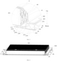
FIG. 3 is a partially enlarged view of part A inFIG. 2 . -
FIG. 4 schematically shows an assembly of a battery tray and a battery core according to an embodiment of the present disclosure. -
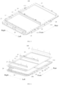
FIG. 5 is a schematic view of a battery tray according to an embodiment of the present disclosure. -
FIG. 6 is an exploded view of a battery tray according to an embodiment of the present disclosure. -
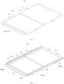
FIG. 7 schematically shows a tray bottom plate of a battery tray according to an embodiment of the present disclosure. -
FIG. 8 schematically shows a frame of a battery tray according to an embodiment of the present disclosure. -
FIG. 9 schematically shows a side beam of a battery tray according to an embodiment of the present disclosure. -
FIG. 10 is a partially enlarged view of part B inFIG. 9 . -
FIG. 11 is a partially enlarged view of an assembly of a battery tray and a battery core according to an embodiment of the present disclosure. -
FIG. 12 is a cross-sectional view of an edge beam according to an embodiment of the present disclosure. -
FIG. 13 is a cross-sectional view of an edge beam according to another embodiment of the present disclosure. -
FIG. 14 is a schematic view of a vehicle according to an embodiment of the present disclosure. - Detail description of the embodiments of the present disclosure will be made in the following, and examples of the embodiments are shown in accompanying drawings, where the same or similar elements or the elements having the same or similar functions are denoted by the same or similar reference numerals throughout the description. The embodiments described below with reference to the accompanying drawings are exemplary and are only used to interpret the present disclosure, instead of limiting the present disclosure.
- An
edge beam 23 for abattery tray 100 according to an embodiment of the present disclosure will be described below with reference toFIGs. 1 to 13 . Multiple edge beams 23 are connected into aframe 20 of thebattery tray 100, and theframe 20 defines a mountingspace 21. Thebattery tray 100 is applied to abattery pack 200, and thebattery tray 100 has atray bottom plate 10 for supporting abattery core 201. Theedge beam 23 is connected to thetray bottom plate 10. Thebattery tray 100 has aplacing slot 111 for accommodating thebattery core 201. - As shown in
FIGs. 1 to 13 , theedge beam 23 according to the embodiment of the present disclosure includes anedge beam body 231. Theedge beam body 231 defines acavity 2311, and theedge beam body 231 has apartition portion 232. Thepartition portion 232 is located in the cavity, and thepartition portion 232 is connected between atop wall 233 of thecavity 2311 and abottom wall 234 of thecavity 2311. Thepartition portion 232 divides thecavity 2311 into afirst sub-cavity 2351 and asecond sub-cavity 2352. Thefirst sub-cavity 2351 and the second sub-cavity 2352 are arranged in a first direction of theedge beam 23 in sequence. The first direction of theedge beam 23 refers to a width direction of theedge beam 23, a width direction of thebattery tray 100, or a length direction of thebattery tray 100. When thebattery tray 100 is arranged in a pattern as shown inFIG. 11 , the width direction of theedge beam 23 refers to a left-right direction as shown inFIG. 11 . It is to be understood that thepartition portion 232 can divide the 2311 cavity intomultiple sub-cavities 235 when connected between thetop wall 233 of thecavity 2311 and thebottom wall 234 of thecavity 2311. When thepartition portion 232 divides thecavity 2311 into twosub-cavities 235, the twosub-cavities 235 are respectively thefirst sub-cavity 2351 and thesecond sub-cavity 2352. When thepartition portion 232 divides thecavity 2311 into foursub-cavities 235, the foursub-cavities 235 are arranged in the first direction of theedge beam 23 in sequence. Twoadjacent sub-cavities 235 form thefirst sub-cavity 2351, and the other twoadjacent sub-cavities 235 form thesecond sub-cavity 2352. When thepartition portion 232 divides thecavity 2311 into sixsub-cavities 235, the sixsub-cavities 235 are arranged in the first direction of theedge beam 23 in sequence. Threeadjacent sub-cavities 235 form thefirst sub-cavity 2351, and the other threeadjacent sub-cavities 235 form thesecond sub-cavity 2352, and so on. The present disclosure will be described by way of example in which thepartition portion 232 divides thecavity 2311 into two sub-cavities 235. - The
first sub-cavity 2351 has a cross-sectional area of S1, thesecond sub-cavity 2352 has a cross-sectional area of S2, and S1 and S2 meet the relation formula: 0.8<S1/S2<1, further, 0.8<S1/S2<0.99. The cross-sectional area of thefirst sub-cavity 2351 refers to the cross-sectional area in the width direction of theedge beam 23, that is, the area of a cross section of the first sub-cavity 2351 that is perpendicular to a length direction of theedge beam 23. The cross-sectional area of thesecond sub-cavity 2352 refers to the cross-sectional area in the width direction of theedge beam 23, that is, the area of a cross section of the second sub-cavity 2352 that is perpendicular to a length direction of theedge beam 23. By dividing thecavity 2311 into thefirst sub-cavity 2351 and thesecond sub-cavity 2352 by thepartition portion 232, the structural strength and rigidity of theedge beam 23 is increased, and the risk of deformation of theedge beam 23 is reduced, to extend the service life of theedge beam 23 and thebattery tray 100. When onecavity 235 of thefirst sub-cavity 2351 and the second sub-cavity 2352 away from the mountingspace 21 of thebattery tray 100 is impacted, the impactedsub-cavity 235 can absorb the impact force, which reduces the impact force transmitted to the inside of thebattery pack 200, and reduces the risk of damage of thebattery core 201 in thebattery pack 200, thus improving the safety of thebattery pack 200 during use. Moreover, when 0.8<S1/S2<1, thebattery pack 200 is ensured to have an appropriate modal, the probability of resonance of thebattery pack 200 can be reduced, and thebattery pack 200 can have a high impact protection capability while thebattery pack 200 is ensured to have an appropriate modal, so that thebattery pack 200 can achieve a balance between the modal of the whole pack and the impact protection of the vehicle. In some embodiments of the present disclosure, thepartition portion 232 is obliquely connected between thetop wall 233 of thecavity 2311 and thebottom wall 234 of thecavity 2311. By obliquely connecting thepartition portion 232 between thetop wall 233 of thecavity 2311 and thebottom wall 234 of thecavity 2311, thepartition portion 232 is reliably supported between thetop wall 233 of thecavity 2311 and thebottom wall 234 of thecavity 2311, whereby the structural strength and rigidity of theedge beam body 231 are increased, the structural stability of theedge beam body 231 is increased, and the risk of deformation of theedge beam 23 is reduced, to extend the service life of theedge beam 23 and thebattery tray 100. - In some embodiments of the present disclosure, as shown in
FIG. 12 , in the first direction of theedge beam 23, thefirst sub-cavity 2351 is located between thesecond sub-cavity 2352 and theplacing slot 111, or it can be considered that thefirst sub-cavity 2351 is located between thesecond sub-cavity 2352 and the mountingspace 21 of thebattery tray 100. When theedge beam 23 is arranged in a pattern as shown inFIG. 12 , the placingslot 111 is left to theedge beam 23, the sub-cavity 235 on the left side is thefirst sub-cavity 2351, and the sub-cavity 235 on the right side is thesecond sub-cavity 2352. By arranging thefirst sub-cavity 2351 and the second sub-cavity 2352 in the width direction of theedge beam 23 in sequence, when thesub-cavity 235 of themultiple sub-cavities 235 away from the placingslot 111 is impacted, that is, the second sub-cavity 2352 on the right side inFIG. 12 is impacted, the impacted second sub-cavity 2352 can absorb the impact force, which reduces the impact force transmitted to the inside of thebattery pack 200, and reduces the risk of damage of thebattery core 201 in thebattery pack 200, thus improving the safety of thebattery pack 200 during use. - In the
battery pack 200, the cross-sectional area of the sub-cavity 235 close to theplacing slot 111 has a great influence on the modal of thebattery pack 200, that is, the cross-sectional area of thefirst sub-cavity 2351 has a great influence on the modal of thebattery pack 200. As the cross-sectional area S1 of the first sub-cavity 2351 increases, the rigidity of thebattery pack 200 becomes worse, the modal of thebattery pack 200 declines, and the probability of resonance of thebattery pack 200 increases. The cross-sectional area of the sub-cavity 235 away from the placingslot 111 has a great influence on the impact protection of the vehicle, that is, the cross-sectional area of thesecond sub-cavity 2352 has a great influence on the impact protection of the vehicle. As the cross-sectional area S2 of the second sub-cavity 2352 increases, the pressurized area of thesecond sub-cavity 2352 becomes smaller, the energy that theedge beam 23 can absorb upon collision of the vehicle with an external force becomes smaller, and the collision safety risk rises. Therefore, when 0.8<S1/S2<1, thebattery pack 200 is ensured to have an appropriate modal, the probability of resonance of thebattery pack 200 can be reduced, and thebattery pack 200 can have a high impact protection capability while thebattery pack 200 is ensured to have an appropriate modal, so that thebattery pack 200 can achieve a balance between the modal of the whole pack and the impact protection of the vehicle. - In some embodiments of the present disclosure, as shown in
FIGs. 11 and 12 , when theedge beam 23 is arranged in a pattern as shown inFIG. 11 , in a direction from an upper end to a lower end of theedge beam 23, thepartition portion 232 is arranged to tilt away from the placingslot 111, or it can be considered that thepartition portion 232 is arranged to tilt away from the mountingspace 21 of thebattery tray 100, or it can be considered that in an up-down direction of thebattery tray 100, thepartition portion 232 is arranged to extend obliquely away from the placingslot 111. Thepartition portion 232 divides thecavity 2311 into thefirst sub-cavity 2351 and thesecond sub-cavity 2352. Through such an arrangement, the structural strength and rigidity of theedge beam 23 is increased, and the stability of theedge beam 23 is improved, thereby improving the capability of theedge beam 23 to support thebattery core 201, and further reducing the risk of deformation of theframe 20. - In some embodiments of the present disclosure, the
partition portion 232 is vertically connected between thetop wall 233 of thecavity 2311 and thebottom wall 234 of thecavity 2311. Through such an arrangement, thepartition portion 232 is more reliably supported between thetop wall 233 of thecavity 2311 and thebottom wall 234 of thecavity 2311, the structural strength of theedge beam 23 is increased, and the stability of theedge beam 23 is improved, thereby improving the capability of theedge beam 23 to support thebattery core 201, and further reducing the risk of deformation of theframe 20. - In some embodiments of the present disclosure, as shown in
FIGs. 11 and 12 , the cross-sectional shape of thefirst sub-cavity 2351 and the cross-sectional shape of the second sub-cavity 2352 are both triangular or trapezoidal. Through such an arrangement, the structural stability of theedge beam 23 is increased, and the risk of deformation of theedge beam 23 is further reduced, thereby further extending the service life of theedge beam 23 and thebattery tray 100. - According to a specific embodiment of the present disclosure, the
first sub-cavity 2351 is located at a side of the second sub-cavity 2352 close to the mountingspace 21. The cross-sectional shape of thefirst sub-cavity 2351 is triangular, and further, isosceles triangle or equilateral triangle. Thebottom wall 234 of thecavity 2311 serves as a bottom wall of the triangle. Through such an arrangement, the structural stability of theedge beam 23 is further increased, and the risk of deformation of theedge beam 23 is further reduced, thereby further extending the service life of theedge beam 23 and thebattery tray 100. - In some optional embodiments, the angle between the
bottom wall 234 of thecavity 2311 and thepartition portion 232 serves as a base angle of the triangle. The base angle is β1 that meets the relation formula: 50°≤β1≤70°. For example, β1 is 60°. Through such an arrangement, the structural stability of theedge beam 23 is further increased, and the risk of deformation of theedge beam 23 is further reduced, thereby further extending the service life of theedge beam 23 and thebattery tray 100. - In some optional embodiments, the vertex angle of the triangle is α1 that meets the relation formula: 50°≤α1≤70°. For example, α1 is 60°. In this way, the cross-sectional shape of the
first sub-cavity 2351 is arranged to be an equilateral triangle. Through such an arrangement, the structural stability of theedge beam 23 is further increased, and the risk of deformation of theedge beam 23 is further reduced, thereby further extending the service life of theedge beam 23 and thebattery tray 100. - According to another specific embodiment of the present disclosure, as shown in
FIGs. 11 and 12 , in the width direction of theedge beam 23, thefirst sub-cavity 2351 is located at a side of the second sub-cavity 2352 close to theplacing slot 111. The cross-sectional shape of thefirst sub-cavity 2351 is arranged to be a trapezoid. Further, thebottom wall 234 of thecavity 2311 serves as a bottom wall of the trapezoid. The angle between thebottom wall 234 of thecavity 2311 and thepartition portion 232 serves as a base angle of the trapezoidal shape of thefirst sub-cavity 2351. The base angle is β2 that meets the relation formula: 50°≤β2≤70°. For example, β2 is 60°. Through such an arrangement, the structural stability of theedge beam 23 is further increased, and the risk of deformation of theedge beam 23 is further reduced, thereby further extending the service life of theedge beam 23 and thebattery tray 100. - In some optional embodiments, as shown in
FIG. 12 , the angle between the two waists of the trapezoidal shape of thefirst sub-cavity 2351 is α2 that meets the relation formula: 50°≤α2≤70°. For example, α2 is 60°. Through such an arrangement, the structural stability of theedge beam 23 is further increased, and the risk of deformation of theedge beam 23 is further reduced, thereby further extending the service life of theedge beam 23 and thebattery tray 100. - In some embodiments of the present disclosure, as shown in
FIG. 12 , the cross-sectional shape of thesecond sub-cavity 2352 is arranged to be a trapezoid. Thebottom wall 234 of thecavity 2311 serves as a top wall of the trapezoidal shape of thesecond sub-cavity 2352, and thetop wall 233 of thecavity 2311 serves as a bottom wall of the trapezoidal shape of thesecond sub-cavity 2352. Through such an arrangement, the structural stability of theedge beam 23 is further increased, and the risk of deformation of theedge beam 23 is further reduced, thereby further extending the service life of theedge beam 23 and thebattery tray 100. - In some embodiments of the present disclosure, the
edge beam body 231 also has a supportingportion 22 extending toward the placingslot 111 of thebattery tray 100. The supportingportion 22 is located below thetray bottom plate 10, and the supportingportion 22 is configured to support thebattery core 201 in thetray bottom plate 10. Theedge beam 23 mainly bears the weight of thebattery core 201. Thetray bottom plate 10 of thebattery tray 100 bears a small fraction of the weight of thebattery core 201, greatly reducing the weight bearing requirement for thetray bottom plate 10. - In some embodiments of the present disclosure, as shown in
FIGs. 12 and13 , theedge beam 23 is configured as an integrally formed component. Further, theedge beam 23 can be formed of an aluminum material, or theedge beam 23 can be formed of a steel material, which is not limited in the present disclosure. Theedge beam 23 can also be made of other metal materials that have the same function as steel. For example, theedge beam 23 is made of a steel material. Theedge beam 23 can be rolled with the steel material, or theedge beam 23 can also be extruded with the steel material. By configuring theedge beam 23 as an integrally formed component, the weight bearing capacity of theedge beam 23 is improved and the risk of deformation of theedge beam 23 is reduced. Theedge beam 23 made of a steel material can withstand a high temperature of 1500°C more, which ensures the integrity of theedge beam 23 upon thermal runaway of thebattery core 201. - According to an embodiment of the present disclosure, as shown in
FIGs. 10 and11 , in the width direction of theedge beam 23, thecavity 2311 has afirst side wall 236 arranged away from the placingslot 111. Thefirst side wall 236 is connected between thetop wall 233 of thecavity 2311 and thebottom wall 234 of thecavity 2311, and thefirst side wall 236 is connected to thepartition portion 232. In some optional embodiments, as shown inFIG. 11 , a lower end of thefirst side wall 236 is connected with a first connectingportion 238 extending toward the interior of thecavity 2311. The first connectingportion 238 is located at a side of thebottom wall 234 of thecavity 2311 facing thetop wall 233 of thecavity 2311, thefirst side wall 236 is connected to thebottom wall 234 of thecavity 2311 and thepartition portion 232 through the first connectingportion 238, and the first connectingportion 238 is fixedly connected to thebottom wall 234 of thecavity 2311. For example, the first connectingportion 238 is welded to thebottom wall 234 of thecavity 2311. Through such an arrangement, the structural strength of theedge beam 23 is further increased, and the stability of theedge beam 23 is further improved. - In some optional embodiments, as shown in
FIGs. 10 and11 , in the width direction of theedge beam 23, thecavity 2311 has asecond side wall 237 close to theplacing slot 111. Thesecond side wall 237 is connected between thetop wall 233 of thecavity 2311 and thebottom wall 234 of thecavity 2311, and thesecond side wall 237 is connected to thepartition portion 232. In some optional embodiments, as shown inFIG. 11 , an upper end of thesecond side wall 237 is connected with a second connectingportion 239 extending toward the interior of thecavity 2311. The second connectingportion 239 is located at a side of thetop wall 233 of thecavity 2311 facing thebottom wall 234 of thecavity 2311, thesecond side wall 237 is connected to thetop wall 233 of thecavity 2311 and thepartition portion 232 through the second connectingportion 239, and the second connectingportion 239 is fixedly connected to thetop wall 233 of thecavity 2311. For example, the second connectingportion 239 is welded to thetop wall 233 of thecavity 2311. Thetop wall 233 of thecavity 2311, thebottom wall 234 of thecavity 2311, thefirst side wall 236 and thesecond side wall 237 define thecavity 2311 together. Through such an arrangement, the structural strength of theedge beam 23 is further increased, and the stability of theedge beam 23 is further improved. - In some optional embodiments, as shown in
FIGs. 10 and11 , theedge beam 23 includes a supportingportion 22. The supportingportion 22 is provided at a side of theedge beam body 231 close to theplacing slot 111, and the supportingportion 22 is configured to support thebattery core 201. That is, theedge beam body 231 is connected with the supportingportion 22 extending toward the placingslot 111. The supportingportion 22 is configured to support thebattery core 201 in thetray bottom plate 10 of thebattery tray 100. The supportingportion 22 supports a lower surface of thetray bottom plate 10 to support thebattery core 201. Theedge beam 23 bears most of the weight of thebattery core 201. Thetray bottom plate 10 of thebattery tray 100 does not bear the weight of thebattery core 201 or only bears a small fraction of the weight of thebattery core 201, greatly reducing the weight bearing requirement for thetray bottom plate 10. - In some optional embodiments, a lower end of the
second side wall 237 is connected with the supportingportion 22 extending toward placingslot 111, the supportingportion 22 can be configured to support thetray bottom plate 10, and thesecond side wall 237 is connected to thebottom wall 234 of thecavity 2311 through the supportingportion 22. In some optional embodiments, as shown inFIG. 12 , in the width direction of theedge beam 23, thebottom wall 234 of thecavity 2311 has astructure strengthening portion 2341 extending below the supportingportion 22. Thestructure strengthening portion 2341 is connected to an end portion of the supportingportion 22 close to thetray bottom plate 10, or it can be considered that thestructure strengthening portion 2341 extends below the supportingportion 22, and an end portion of thebottom wall 234 of thecavity 2311 close to theplacing slot 111 is connected to an end portion of thestructure strengthening portion 2341 close to theplacing slot 111. Further, thestructure strengthening portion 2341 is provided with a boss (that is, boss structure 2391) protruding toward the supportingportion 22, and theboss structure 2391 is connected to the supportingportion 22. Through such an arrangement, the structural strength of theedge beam 23 is further increased, and the stability of theedge beam 23 is further improved. - In some optional embodiments, the
structure strengthening portion 2341 is provided withmultiple boss structures 2391. Themultiple boss structures 2391 are arranged in the width direction of theedge beam 23 in sequence. At least oneboss structure 2391 of themultiple boss structures 2391 is located below thebattery core 201. Such an arrangement enables theboss structure 2391 to support thebattery core 201, thereby further improving the weight bearing capacity of theframe 20 and reducing the risk of deformation of the supportingportion 22. - According to another embodiment of the present disclosure, as shown in
FIG. 13 , in the width direction of theedge beam 23, thecavity 2311 has afirst side wall 236 arranged away from the placingslot 111. Thefirst side wall 236 is connected between thetop wall 233 of thecavity 2311 and thebottom wall 234 of thecavity 2311. Thecavity 2311 has asecond side wall 237 close to theplacing slot 111. Thesecond side wall 237 is connected between thetop wall 233 of thecavity 2311 and thebottom wall 234 of thecavity 2311. Thetop wall 233 of thecavity 2311, thebottom wall 234 of thecavity 2311, thefirst side wall 236 and thesecond side wall 237 define thecavity 2311 together. Thebottom wall 234 of thecavity 2311 extends toward the placingslot 111 to form the supportingportion 22 configured to support thetray bottom plate 10. The supportingportion 22 is located below thetray bottom plate 10, and the supportingportion 22 extends to a position below thebattery core 201. Such an arrangement enables the supportingportion 22 to support thebattery core 201, thereby further improving the weight bearing capacity of theedge beam 23. - In some embodiments of the present disclosure, the
second side wall 237 is obliquely connected between thetop wall 233 of thecavity 2311 and thebottom wall 234 of thecavity 2311. In the direction from the upper end to the lower end of theedge beam 23, thesecond side wall 237 is arranged to tilt toward the placingslot 111. Through such an arrangement, the structural strength of theedge beam 23 is further increased, and the stability of theedge beam 23 is further improved, thereby further improving the capability of theedge beam 23 to support thebattery core 201, and further reducing the risk of deformation of theframe 20. - As shown in
FIGs. 1 to 13 , thebattery tray 100 according to an embodiment of the present disclosure includes: a tray bottom plate 10 (thetray bottom plate 10 according to the above embodiment) and a frame 20 (theframe 20 according to the above embodiment). Thetray bottom plate 10 includes abottom plate body 11 and anextension portion 12. Thebottom plate body 11 defines aplacing slot 111 for accommodating abattery core 201 or a battery module. In the present disclosure, description is made by way of example in which theplacing slot 111 accommodates thebattery core 201. Thebattery core 201 can be bonded in theplacing slot 111 by a structural adhesive. In some optional embodiments, the placingslot 111 has abottom wall 113 of the placing slot. Thebottom wall 113 of the placing slot has a pressurizedarea 112 for supporting thebattery core 201. Thepressurized area 112 refers to an area where the orthographic projection of thebottom wall 113 of the placing slot overlaps with the orthographic projection of thebattery core 201 in a height direction of thebattery tray 100, when thebattery core 201 is mounted in theplacing slot 111. Alternatively, it can be considered as a contact area between thebattery core 201 and thebottom wall 113 of the placing slot when thebattery core 201 is mounted in theplacing slot 111. The contact area includes an area where thebattery core 201 is in direct contact or indirect contact with thebottom wall 113 of the placing slot. For example, thebattery core 201 is in indirect contact with thebottom wall 113 of the placing slot when there is an adhesive or a cooling structure between thebattery core 201 and thebottom wall 113 of the placing slot, and thebattery core 201 is in direct contact with thebottom wall 113 of the placing slot when there is no an additional object between thebattery core 201 and thebottom wall 113 of the placing slot. Alternatively, it can be considered that an area where the weight of thebattery core 201 directly acts on thebottom wall 113 of the placing slot is thepressurized area 112. In the height direction of thebattery tray 100, the orthogonal projection of thebottom wall 113 of the placing slot is also the projection of thebottom wall 113 of placing slot to a plane perpendicular to the height direction of thebattery tray 100. In the height direction of thebattery tray 100, the orthogonal projection of thebattery core 201 is the projection of thebattery core 201 in a plane perpendicular to the height direction of thebattery tray 100. - When the
battery core 201 is mounted in thebattery tray 100, thebattery core 201 is located in thepressurized area 112 of theplacing slot 111. Theextension portion 12 is arranged to extend along a peripheral edge of thebottom plate body 11. Further, theextension portion 12 is configured as a loop structure. Particularly, theextension portion 12 is configured as a closed-loop structure. - The
frame 20 defines the mountingspace 21, and thebottom plate body 11 is mounted to theframe 20. Further, thebottom plate body 11 is fixedly mounted to theframe 20. Thebottom plate body 11 may be bonded to theframe 20, or thebottom plate body 11 may be connected to theframe 20 by a bolt. The specific assembly method of thebottom plate body 11 and theframe 20 is not specifically limited, and can be selected according to actual needs. Thebottom plate body 11 is mounted in the mountingspace 21, and theextension portion 12 is located outside the mountingspace 21. In the height direction of thebattery tray 100, theextension portion 12 is located above theframe 20 and arranged on theframe 20. - In some embodiments of the present disclosure, as shown in
FIGs. 6 and8 , theframe 20 includes a side beam, afront beam 24 and arear beam 25. At least one of the side beam, thefront beam 24 and therear beam 25 is theedge beam 23 according to the above embodiment. Theedge beam 23, thefront beam 24 and therear beam 25 are connected to define the mountingspace 21. The connection of the side beam, thefront beam 24 and therear beam 25 includes direct connection and indirect connection. For example, the connection of the side beam and thefront beam 24 is described. The side beam and thefront beam 24 can be directly connected, or the side beam and thefront beam 24 can also be indirectly connected by an additional beam. - In some optional embodiments, the side beam and/or the
front beam 24 and/or therear beam 25 has the supportingportion 22 extending toward the mountingspace 21, or it can be considered that at least one of the side beam, thefront beam 24 and therear beam 25 has the supportingportion 22 extending toward the mountingspace 21. The supportingportion 22 is configured to support thetray bottom plate 10. Two side beams, onerear beam 25 and onefront beam 24 are provided. When theframe 20 is arranged in a pattern as shown inFIG. 8 , the two side beams are spaced away in the left-right direction inFIG. 8 , and thefront beam 24 and therear beam 25 are connected between the two side beams. Thefront beam 24 and therear beam 25 are spaced away in the front-rear direction of theframe 20. In this way, thefront beam 24, therear beam 25 and the two side beams jointly define the mountingspace 21. When thebattery core 201 is arranged to extend in the left-right direction as shown inFIG. 8 , by arranging the supportingportion 22 on the side beam, eachbattery core 201 is ensured to be supported by the supportingportion 22, which can further ensure that the supportingportion 22 supports thebattery core 201, and further ensure that theframe 20 is mainly used for bearing the weight of thebattery core 201. Consequently, the arrangement of the position of the supportingportion 22 is reasonable. It can be understood that when thebattery tray 100 is mounted on avehicle 2000, the width direction of thebattery tray 100 may be consistent with the width direction of the vehicle, and the length direction of thebattery tray 100 may be consistent with the length direction of the vehicle. Definitely, the width direction of thebattery tray 100 may be consistent with the length direction of the vehicle, and the length direction of thebattery tray 100 may be consistent with the width direction of the vehicle. - Further, the supporting
portion 22 is configured to support thepressurized area 112 of thetray bottom plate 10. As shown inFIGs. 6 ,8 and11 , description is made by way of example in which thebattery tray 100 is arranged in an up-down direction in the present disclosure. After thebottom plate body 11 is mounted in the mountingspace 21, theextension portion 12 is arranged outside the mountingspace 21. In the up-down direction of thebattery tray 100, theextension portion 12 is arranged corresponding to theframe 20. Particularly, as shown inFIG. 11 , theextension portion 12 is located above theframe 20, and theextension portion 12 is arranged to direct face theframe 20. In the up-down direction of thebattery tray 100, theextension portion 12 covers the entire upper surface of theframe 20. - As shown in
FIG. 11 , when thebattery core 201 is mounted in theplacing slot 111, thebattery core 201 is located in thepressurized area 112, and the supportingportion 22 supports thepressurized area 112. The weight of thebattery core 201 is loaded on theframe 20, theframe 20 bears most of the weight of thebattery core 201, and thetray bottom plate 10 does not bear the weight of thebattery core 201 or bears a small fraction of the weight of thebattery core 201, greatly reducing the weight bearing requirement for thetray bottom plate 10. Therefore, thetray bottom plate 10 can be made of materials with lower strength and small thickness. In some optional embodiments, thetray bottom plate 10 is configured as a nonmetallic member. In some optional embodiments, thetray bottom plate 10 is configured as an insulating member. Thetray bottom plate 10 may be formed of a lightweight nonmetallic composite material. For example, the lightweight nonmetallic composite material can be made of a resin and glass fiber, where the resin can be epoxy resin or polyurethane, which is not limited in the present disclosure. The lightweight composite material can also be a composite material that is made of other resins and glass fiber and has the same function. Such an arrangement can reduce the weight of thetray bottom plate 10, which is beneficial to the lightweight design of thebattery tray 100 and thebattery pack 200. The existingtray bottom plate 10 is made of an aluminum material. In the present disclosure, thetray bottom plate 10 is formed of a nonmetallic composite material, which reduces the production cost of thetray bottom plate 10, and facilitates the reduction of the production cost of thebattery tray 100 and thebattery pack 200. It is to be understood that thetray bottom plate 10 formed of a nonmetallic composite material has excellent electrical insulation performance. When a serious bottom scratching accident occurs to thevehicle 2000, thebattery pack 200 will not have the risks such as high-voltage arcing. - In some optional embodiments, the
tray bottom plate 10 is configured as an integrally formed component. Thetray bottom plate 10 is molded with a lightweight nonmetallic composite material. During the molding process, thetray bottom plate 10 has good air tightness formed after the resin is melted to flow and then solidified, and thetray bottom plate 10 is ensured to have good flatness and dimensional accuracy by molding, thus ensuring the sealing function of thetray bottom plate 10. Theframe 20 can be formed by tailor-welding with a metal. After tailor-welding, the strength of the welded structure and necessary flatness of the product need to be ensured. The tailor-welding efficiency is high, which improves the production efficiency of thebattery tray 100. Moreover, thetray bottom plate 10 is responsible for sealing; and there is no need for weld grinding and air tightness testing, and no risk of sealing failure caused by welding. Thetray bottom plate 10 can be formed by molding with a composite material. Thetray bottom plate 10 has high production efficiency, and the precision of the mold is high, so a high flatness can be attained. Accordingly, the size requirement for thebattery core 201 is reduced. - In addition, the existing
battery tray 100 does not divide the product structure with respect to the functions of weight bearing and sealing. In the production of thebattery tray 100, both the overall weight bearing capacity and the sealing performance need to meet the requirements, resulting in low manufacturing efficiency and yield of thebattery tray 100. In the present disclosure, the functions of weight bearing and sealing are divided. Theframe 20 is mainly responsible for weight bearing, and thetray bottom plate 10 is mainly responsible for sealing. These improve the manufacturing efficiency and yield of thebattery tray 100. - Therefore, with the cooperation of the
tray bottom plate 10 and theframe 20 where theframe 20 mainly bears the weight of thebattery core 201 and thetray bottom plate 10 bears only a small fraction of the weight of thebattery core 201; and thetray bottom plate 10 is mainly responsible for sealing, the thickness of thetray bottom plate 10 is reduced, and thetray bottom plate 10 can be formed of a lightweight composite material, which is beneficial to the lightweight design and reduction of the production cost of thebattery tray 100 and thebattery pack 200. After thetray bottom plate 10 and theframe 20 are assembled, there is no risk of sealing failure of thebattery tray 100 caused by welding, and there is no need for weld grinding and air tightness testing of thebattery tray 100, thus improving the production efficiency of thebattery tray 100. - In some embodiments of the present disclosure, the
tray bottom plate 10 and theframe 20 are in sealed connection. Theframe 20 is provided with multiple bolt holes 28, theextension portion 12 is provided with multiple avoidance throughholes 122, and the multiple bolt holes 28 are arranged in one-to-one correspondence with the multiple avoidance throughholes 122. Multiple rivet nuts are embedded in theframe 20, and the multiple rivet nuts are arranged in one-to-one correspondence with the multiple bolt holes 28. The rivet nut extends through the escape throughhole 122 and thebolt hole 28. Thebattery pack 200 includes acover 40, thecover 40 and thetray bottom plate 10 jointly define anaccommodating cavity 41 for accommodating thebattery core 201, and thecover 40 is connected to theframe 20. Further, thecover 40 is covered at an open end of theplacing slot 111 to define theaccommodating cavity 41. Theextension portion 12 is sandwiched between thecover 40 and theframe 20. The bolt extends through thecover 40, the avoidance throughhole 122 of theextension portion 12 and thebolt hole 28 of theframe 20, and is connected to the rivet nut, whereby thecover 40, thetray bottom plate 10 and theframe 20 are assembled together. Through the sealed connection between thetray bottom plate 10 and theframe 20, sealing is formed between the bolt and thebolt hole 28, so that the leak-tightness of thebattery tray 100 is improved, the water vapor can be prevented from flowing into the placingslot 111 through thebolt hole 28 on theframe 20, and thebattery pack 200 can also be prevented from being short-circuited, thereby improving the safety of thebattery pack 200 during use. - In some embodiments of the present disclosure, as shown in
FIG. 11 , thetray bottom plate 10 and theframe 20 are sealed connected by a sealingstructure 13. Further, the sealingstructure 13 is configured as a sealant, and the sealingstructure 13 may also be configured as a rubber member, which is not limited in the present disclosure. The sealingstructure 13 can also be configured as a seal having the same function as the sealant. The sealingstructure 13 can be sandwiched in the whole space between thetray bottom plate 10 and theframe 20, or the sealingstructure 13 can be sandwiched in part of the space between thetray bottom plate 10 and theframe 20. The sealingstructure 13 can be arranged to surround thebolt hole 28 and the avoidance throughhole 122. Further, the sealingstructure 13 can extend into thebolt hole 28 and the avoidance throughhole 122. Through such an arrangement, sealed connection can be enabled between thetray bottom plate 10 and theframe 20, to effectively prevent water vapor from flowing into theaccommodating cavity 41 via thebolt hole 28 on theframe 20. - In some embodiments of the present disclosure, as shown in
FIG. 11 , the sealingstructure 13 is provided between theextension portion 12 and theframe 20. Since the avoidance throughhole 122 is provided in theextension portion 12, by providing the sealingstructure 13 between theextension portion 12 and theframe 20, the sealingstructure 13 can seal thebolt hole 28 and the avoidance throughhole 122, making the arrangement of the position of the sealingstructure 13 reasonable. - In some embodiments of the present disclosure, as shown in
FIG. 11 , when thebattery tray 100 is arranged in a pattern as shown inFIG. 11 , in the height direction of thebattery tray 100, the orthographic projection of the supportingportion 22 and the orthographic projection of thepressurized area 112 have an overlapping area. When thebattery core 201 is accommodated in theplacing slot 111, such an arrangement can ensure that the supportingportion 22 supports thebattery core 201, and ensure that theframe 20 is mainly used for bearing the weight of thebattery core 201. - In some embodiments of the present disclosure, the
bottom wall 113 of theplacing slot 111 is formed with apressurized area 112. Alternatively, it can be considered that thepressurized area 112 is provided on thebottom wall 113 of theplacing slot 111. As shown inFIG. 11 , when thebattery tray 100 is arranged in a pattern as shown inFIG. 11 , the supportingportion 22 is located below thebottom plate body 11, and the supportingportion 22 supports thebottom wall 113. This arrangement ensures that the supportingportion 22 is located below and support thepressurized area 112, which can further ensure that the supportingportion 22 supports thebattery core 201, and further ensure that theframe 20 is mainly used for bearing the weight of thebattery core 201. Consequently, the arrangement of the position of thepressurized area 112 is reasonable. - In some embodiments of the present disclosure, as shown in
FIG. 8 , theframe 20 further includes a supportingbeam 26. The supportingbeam 26 is connected between twoedge beams 23, the supportingbeam 26 is connected between thefront beam 24 and therear beam 25, the supportingbeam 26 is connected between thefront beam 24 and theedge beam 23, or the supportingbeam 26 is connected between therear beam 25 and theedge beam 23. This arrangement can improve the structural strength of theframe 20 and thus the structural strength of thebattery tray 100. - In some embodiments of the present disclosure, as shown in
FIGs. 5 and 6 , thebattery tray 100 further includes anexpansion beam 27. Theexpansion beam 27 is provided on a side of thetray bottom plate 10 away from theframe 20. When thebattery tray 100 is arranged in a pattern as shown inFIGs. 5 and 6 , theexpansion beam 27 is provided above thetray bottom plate 10, and theexpansion beam 27 is mounted on thesupport beam 26 by a bolt. After thebattery core 201 is mounted in theplacing slot 111, when thebattery core 201 expands, theexpansion beam 27 restrains thebattery core 201, to improve the safety of thebattery core 201 during use. - Further, multiple supporting
beams 26 are provided. The multiple supportingbeams 26 are spaced away in sequence in a length direction of theedge beam 23. The length direction of theedge beam 23 refers to the front-rear direction inFIG. 6 . Multiple expansion beams 27 are provided, and themultiple expansion beams 27 are spaced away in sequence in the length direction of theedge beam 23. Themultiple expansion beams 27 and the multiple supportingbeams 26 are arranged in one-to-one correspondence, and oneexpansion beam 27 is mounted on one supportingbeam 26 by a bolt, to stably mount theexpansion beam 27 on theframe 20. - In some embodiments of the present disclosure, as shown in
FIG. 11 , the supportingportion 22 is provided close to the lower end of theedge beam 23. Alternatively, it can be considered that the supportingportion 22 is provided close to an end portion of theedge beam 23 away from thetray bottom plate 10. After thebottom plate body 11 is mounted in the mountingspace 21, by providing the supportingportion 22 close to the end portion of theedge beam 23 away from thetray bottom plate 10, the supportingportion 22 is ensured to be located below and support thebottom plate body 11, and thebottom plate body 11 is ensured to be mounted in the mountingspace 21. - In some embodiments of the present disclosure, as shown in
FIGs. 5 to 7 , and11 , when thebattery tray 100 is arranged in a pattern as shown inFIG. 11 , the upper end of theplacing slot 111 is arranged to be open, and thebattery core 201 can be placed in theplacing slot 111 through the open end of theplacing slot 111. Theextension portion 12 is arranged to extend along a peripheral edge at the open end of theplacing slot 111. As shown inFIG. 11 , theextension portion 12 is connected to an upper end of thebottom plate body 11. After thebottom plate body 11 is mounted in the mountingspace 21, such an arrangement enables theextension portion 12 to be provided outside the placingslot 111, and ensures that theextension portion 12 is arranged corresponding to theframe 20 in the up-down direction of thebattery tray 100, thereby ensuring the sealing of thebattery tray 100. - In some embodiments of the present disclosure, as shown in
Figs. 8 ,10 and11 , a surface of the supportingportion 22 close to thetray bottom plate 10 is configured as a planar surface. That is to say, as shown inFIG. 11 , the upper surface of the supportingportion 22 is a planar surface, and such an arrangement can ensure the supporting area between the supportingportion 22 and thebottom plate body 11 and allows the supportingportion 22 to well support thebattery core 201. - In some embodiments of the present disclosure, the supporting
portion 22 is located below thebottom plate body 11 and fixedly connected to thebottom plate body 11. In some optional embodiments, thetray bottom plate 10 is bonded to theframe 20. Further, the supportingportion 22 and thebottom plate body 11 are bonded by applying an adhesive (such as structural adhesive) between thetray bottom plate 10 and theframe 20. The dimensional tolerance of theframe 20 is absorbed by controlling the thickness of the adhesive. Moreover, thetray bottom plate 10 has good flatness, and the manufacturing requirements for thetray bottom plate 10 and theframe 20 are reduced by taking advantage of the characteristic that the adhesive can absorb the tolerance. Moreover, when the existingtray bottom plate 10 and theframe 20 are welded, thetray bottom plate 10 tend to deform during the welding process, which increases the size requirements for thebattery core 201 in the subsequent assembly process of thebattery pack 200, and affects the assembly efficiency of thebattery pack 200. In the present disclosure, thetray bottom plate 10 and theframe 20 are bonded to avoid the welded connection of thetray bottom plate 10 and theframe 20. This can prevent the deformation of thetray bottom plate 10, reduce the size requirements for thebattery core 201 in the subsequent assembly process of thebattery pack 200, and improve the assembly efficiency of thebattery pack 200. - In some embodiments of the present disclosure, the
tray bottom plate 10 is configured as an integrally formed component. Thetray bottom plate 10 is molded with a lightweight composite material. During the molding process, thetray bottom plate 10 has good air tightness formed after the resin is melted to flow and then solidified, and thetray bottom plate 10 is ensured to have good flatness and dimensional accuracy by molding, thus ensuring the sealing function of thetray bottom plate 10. - In some embodiments of the present disclosure, the
frame 20 is configured as a metal piece, theframe 20 can be formed of an aluminum material, or theframe 20 can also be formed of a steel material, which is not limited in the present disclosure. Theframe 20 can also be made of other metal materials that have the same function as steel. For example, theframe 20 is made of a steel material, where theframe 20 is rolled with the steel material, or theframe 20 can also be extruded with the steel material. By configuring theframe 20 as a metal member, the weight bearing capacity of theframe 20 can be improved and the risk of deformation of theframe 20 can be reduced. - In some embodiments of the present disclosure, as shown in
FIGs. 5 and 6 , theframe 20 is connected with a liftinglug structure 30. The liftinglug structure 30 is provided with a mounting hole, and the liftinglug structure 30 is mounted on thevehicle 2000 by a fastener (such as a bolt), so as to achieve the purpose of mounting thebattery pack 200 on thevehicle 2000. - As shown in
FIGs. 1 to 11 , thebattery pack 200 according to the embodiment of the present disclosure includes abattery core 201, abattery tray 100 and acover 40. Thebattery tray 100 is abattery tray 100 according to the above embodiment. Thebattery tray 100 has aplacing slot 111, and thebattery core 201 is accommodated in theplacing slot 111. Thecover 40 and thetray bottom plate 10 jointly define anaccommodating cavity 41 for accommodating thebattery core 201, and thecover 40 is connected to theframe 20. Further, thecover 40 is covered at an open end of theplacing slot 111 to define theaccommodating cavity 41. Theextension portion 12 is sandwiched between thecover 40 and theframe 20. The bolt extends through thecover 40. Thecover 40, thetray bottom plate 10 and theframe 20 are assembled together by theextension portion 12 and theframe 20. Further, a seal 203 (such as a sealing ring) is sandwiched between theextension portion 12 and thecover 40, and theseal 203 can seal theaccommodating cavity 41. Thecover 40 and thetray bottom plate 10 define a sealed insulating cavity (i.e. the accommodating cavity 41). After thebattery core 201 is placed in theaccommodating cavity 41, thebattery core 201 can be completely isolated from theframe 20, such that thebattery core 201 is in a completely insulated environment, and thebattery pack 200 has no risk of electric leakage. - In some embodiments of the present disclosure, as shown in
FIG. 1 , thebattery pack 200 further includes: apress plate 202. Thepress plate 202 is configured as a closed ring structure. Thecover 40, theseal 203 and theextension portion 12 are sandwiched between thepress plate 202 and theframe 20. A bolt extends through thepress plate 202, thecover 40, theextension portion 12 and theframe 20 to assemble thepress plate 202, thecover 40, thetray bottom plate 10 and theframe 20 together. Thepress plate 202 allows thewhole seal 203 to be uniformly pressed, and ensures the reliable sealing of theaccommodating cavity 41. - As shown in
FIG. 14 , thevehicle 2000 according to the embodiment of present disclosure includes abattery pack 200 according to above embodiment. Thebattery pack 200 is mounted on thevehicle 2000 to provide electric energy for thevehicle 2000. Theframe 20 of thebattery pack 200 bears most of the weight of thebattery core 201, and thetray bottom plate 10 bears only a small fraction of the weight of thebattery core 201. Thetray bottom plate 10 is mainly responsible for sealing. Thetray bottom plate 10 can be formed of a lightweight composite material, which is beneficial to the lightweight design and reduction of the production cost of thebattery tray 100, thebattery pack 200 and thevehicle 2000. After thetray bottom plate 10 and theframe 20 are assembled, there is no risk of sealing failure of thebattery tray 100 caused by welding, and there is no need for weld grinding and air tightness testing of thebattery tray 100, which improves the production efficiency of thebattery tray 100 and thevehicle 2000. Moreover, thetray bottom plate 10 formed of a composite material has excellent electrical insulation performance. When a serious bottom scratching accident occurs to thevehicle 2000, thebattery pack 200 will not have the risks such as high-voltage arcing, so the safety of thevehicle 2000 is improved. - In the description of the specification, the description with reference to the terms "an embodiment", "some embodiments", "exemplary embodiments", "example", "specific example", or "some examples" and so on means that specific features, structures, materials or characteristics described in connection with the embodiment or example are embraced in at least one embodiment or example of the present disclosure. In the specification, exemplary descriptions of the foregoing terms do not necessarily refer to the same embodiment or example. In addition, the described specific features, structures, materials, or characteristics may be combined in a proper manner in any one or more of the embodiments or examples.
- Although embodiments of the present disclosure has been illustrated and described above, a person of ordinary skill in the art should understand that various changes, modifications, replacements and variations can be made to the embodiments without departing from the principles and spirit of the present disclosure, and the scope of the present disclosure is as defined by the appended claims and their equivalents.
Claims (20)
- An edge beam (23) for a battery tray (100), the battery tray (100) having a placing slot (111) for accommodating a battery core (201), the edge beam (23) comprising:
an edge beam body (231), the edge beam body (231) defining a cavity (2311), the edge beam body (231) having a partition portion (232), the partition portion (232) being located in the cavity (2311), the partition portion (232) being connected between a top wall (233) and a bottom wall (234) of the cavity (2311) to divide the cavity (2311) into a first sub-cavity (2351) and a second sub-cavity (2352), the first sub-cavity (2351) and the second sub-cavity (2352) being arranged in a first direction of the edge beam (23) in sequence, the first sub-cavity (2351) having a cross-sectional area of S1, the second sub-cavity (2352) having a cross-sectional area of S2, and S1 and S2 meeting the relation formula: 0.8<S1/S2<1. - The edge beam (23) for a battery tray (100) according to claim 1, wherein in the first direction of the edge beam (23), the first sub-cavity (2351) is located between the second sub-cavity (2352) and the placing slot (111).
- The edge beam (23) for a battery tray (100) according to claim 1 or 2, wherein the partition portion (232) is obliquely connected between the top wall (233) and the bottom wall (234) of the cavity (2311).
- The edge beam (23) for a battery tray (100) according to any one of claims 1 to 3, wherein in a direction from an upper end to a lower end of the edge beam (23), the partition portion (232) is arranged to tilt away from the placing slot (111).
- The edge beam (23) for a battery tray (100) according to any one of claims 1 to 4, wherein the cross-sectional shape of the first sub-cavity (2351) and the cross-sectional shape of the second sub-cavity (2352) are both triangular or trapezoidal.
- The edge beam (23) for a battery tray (100) according to any one of claims 1 to 5, wherein the edge beam (23) is configured as an integrally formed component.
- The edge beam (23) for a battery tray (100) according to any one of claims 1 to 6, wherein in a width direction of the edge beam (23), the cavity (2311) has a first side wall (236) arranged away from the placing slot (111), the first side wall (236) is connected between the top wall (233) and the bottom wall (234) of the cavity (2311), and the first side wall (236) is connected to the partition portion (232).
- The edge beam (23) for a battery tray (100) according to claim 7, wherein a lower end of the first side wall (236) is connected with a first connecting portion (238) extending toward the interior of the cavity (2311), the first connecting portion (238) is located at a side of the bottom wall (234) of the cavity (2311) facing the top wall (233) of the cavity (2311), the first side wall (236) is connected to the bottom wall (234) of the cavity (2311) and the partition portion (232) through the first connecting portion (238), and the first connecting portion (238) is fixedly connected to the bottom wall (234) of the cavity (2311).
- The edge beam (23) for a battery tray (100) according to any one of claims 1 to 8, wherein the cavity (2311) has a second side wall (237) close to the placing slot (111), the second side wall (237) is connected between the top wall (233) and the bottom wall (234) of the cavity (2311), and the second side wall (237) is connected to the partition portion (232).
- The edge beam (23) for a battery tray (100) according to claim 9, wherein an upper end of the second side wall (237) is connected with a second connecting portion (239) extending toward the interior of the cavity (2311), the second connecting portion (239) is located at a side of the top wall (233) of the cavity (2311) facing the bottom wall (234) of the cavity (2311), the second side wall (237) is connected to the top wall (233) of the cavity (2311) and the partition portion (232) through the second connecting portion (239), and the second connecting portion (239) is fixedly connected to the top wall (233) of the cavity (2311).
- The edge beam (23) for a battery tray (100) according to claim 9 or 10, the edge beam (23) further comprising a supporting portion (22), the supporting portion (22) being provided at a side of the edge beam body (231) close to the placing slot (111), and the supporting portion (22) being configured to support the battery core (201).
- The edge beam (23) for a battery tray (100) according to claim 11, wherein a lower end of the second side wall (237) is connected with the supporting portion (22) extending toward the placing slot (111), and the second side wall (237) is connected to the bottom wall (234) of the cavity (2311) through the supporting portion (22).
- The edge beam (23) for a battery tray (100) according to any one of claims 9 to 12, wherein the second side wall (237) is obliquely connected between the top wall (233) and the bottom wall (234) of the cavity (2311), and in the direction from the upper end to the lower end of the edge beam (23), the second side wall (237) is arranged to tilt toward the placing slot (111).
- The edge beam (23) for a battery tray (100) according to claim 11 or 12, wherein in the width direction of the edge beam (23), the bottom wall (234) of the cavity (2311) has a structure strengthening portion (2341) extending below the supporting portion (22), and the structure strengthening portion (2341) is connected to an end portion of the supporting portion (22) close to the placing slot (111).
- The edge beam (23) for a battery tray (100) according to claim 14, wherein the structure strengthening portion (2341) has a boss protruding toward the supporting portion (22), and the boss is connected to the supporting portion (22).
- The edge beam (23) for a battery tray (100) according to any one of claims 1 to 6, wherein in the width direction of the edge beam (23), the cavity (2311) has a first side wall (236) arranged away from the placing slot (111), the first side wall (236) is connected between the top wall (233) and the bottom wall (234) of the cavity (2311), and
the cavity (2311) has a second side wall (237) close to the placing slot (111), the second side wall (237) is connected between the top wall (233) and the bottom wall (234) of the cavity (2311), the top wall (233) of the cavity (2311), the bottom wall (234) of cavity (2311), the first side wall (236), and the second side wall (237) defining the cavity (2311) together, and the bottom wall (234) of the cavity (2311) extending toward the placing slot (111) to form the supporting portion (22) configured to support the battery core (201). - A battery tray (100), comprising an edge beam (23) for a battery tray (100) according to any one of claims 1 to 16.
- The battery tray (100) according to claim 17, comprising:a tray bottom plate (10), the tray bottom plate (10) comprising a bottom plate body (11) and an extension portion (12), the bottom plate body (11) defining a placing slot (111) for accommodating a battery core (201), the extension portion (12) extending along a peripheral edge of the bottom plate body (11); anda frame (20), the frame (20) comprising a side beam, a front beam (24), and a rear beam (25), at least one of the side beam, the front beam (24), and the rear beam (25) being the edge beam (23), the side beam, the front beam (24), and the rear beam (25) being connected to form a mounting space (21), the bottom plate body (11) being mounted in the mounting space (21), in a height direction of the battery tray (100), the extension portion (12) being located above the frame (20) and arranged on the frame (20), at least one of the side beam, the front beam (24), and the rear beam (25) having a supporting portion (22) extending toward the mounting space and, the supporting portion (22) being configured to support the tray bottom plate (10).
- A battery pack (200), comprising a battery core (201) and a battery tray (100) according to claim 17 or 18, the battery tray (100) having a placing slot (111), and the battery core (201) being accommodated in the placing slot (111).
- A vehicle (2000), comprising a battery pack (200) according to claim 19.
Applications Claiming Priority (2)
| Application Number | Priority Date | Filing Date | Title |
|---|---|---|---|
| CN202210249500.3A CN116799424B (en) | 2022-03-14 | 2022-03-14 | Side beams for battery trays, battery trays, battery packs, and vehicles. |
| PCT/CN2023/081413 WO2023174295A1 (en) | 2022-03-14 | 2023-03-14 | Edge beam for battery tray, battery tray, battery pack, and vehicle |
Publications (2)
| Publication Number | Publication Date |
|---|---|
| EP4439832A1 true EP4439832A1 (en) | 2024-10-02 |
| EP4439832A4 EP4439832A4 (en) | 2025-04-16 |
Family
ID=88022311
Family Applications (1)
| Application Number | Title | Priority Date | Filing Date |
|---|---|---|---|
| EP23769797.4A Pending EP4439832A4 (en) | 2022-03-14 | 2023-03-14 | Edge beam for battery tray, battery tray, battery pack, and vehicle |
Country Status (7)
| Country | Link |
|---|---|
| US (1) | US20240347837A1 (en) |
| EP (1) | EP4439832A4 (en) |
| JP (1) | JP7853425B2 (en) |
| KR (1) | KR20240119091A (en) |
| CN (1) | CN116799424B (en) |
| CA (1) | CA3242452A1 (en) |
| WO (1) | WO2023174295A1 (en) |
Families Citing this family (6)
| Publication number | Priority date | Publication date | Assignee | Title |
|---|---|---|---|---|
| WO2021130523A1 (en) * | 2019-12-24 | 2021-07-01 | Arcelormittal | Protective element for a battery pack of a hybrid or electric vehicle and process for the assembling of a reinforced battery pack |
| CN115939630B (en) * | 2022-10-26 | 2025-01-21 | 华菱安赛乐米塔尔汽车板有限公司 | Battery pack and manufacturing method thereof, and vehicle |
| CN119864571A (en) * | 2023-10-19 | 2025-04-22 | 宁德时代新能源科技股份有限公司 | Box, battery and power consumption device |
| CN121097304A (en) * | 2024-06-06 | 2025-12-09 | 宁德时代新能源科技股份有限公司 | Battery box, battery and power consumption device |
| CN119297497A (en) * | 2024-09-13 | 2025-01-10 | 惠州亿纬锂能股份有限公司 | Beam structure, battery box and battery pack |
| CN119581768B (en) * | 2024-12-03 | 2025-09-19 | 蜂巢能源科技股份有限公司 | Battery pack side beams and battery pack shell |
Family Cites Families (26)
| Publication number | Priority date | Publication date | Assignee | Title |
|---|---|---|---|---|
| JP6020958B2 (en) * | 2012-07-13 | 2016-11-02 | 三菱自動車工業株式会社 | Battery pack tray |
| JP6304587B2 (en) * | 2014-03-06 | 2018-04-04 | 三菱自動車工業株式会社 | Battery pack for electric vehicles |
| CN204415516U (en) * | 2015-01-05 | 2015-06-24 | 广州汽车集团股份有限公司 | Fore sub frame mounting structure and automobile |
| CN107293660B (en) * | 2016-04-11 | 2020-11-20 | 比亚迪股份有限公司 | A vehicle tray assembly for installing a power battery and an automobile |
| CN107293659B (en) * | 2016-04-11 | 2019-12-20 | 比亚迪股份有限公司 | Battery tray, battery tray assembly and electric automobile |
| JP6514248B2 (en) * | 2017-02-17 | 2019-05-15 | 本田技研工業株式会社 | Substructure of car body |
| CN206834227U (en) * | 2017-06-28 | 2018-01-02 | 长城汽车股份有限公司 | Frame beam, battery bag lower house and the vehicle of battery bag lower house |
| WO2020000090A1 (en) * | 2018-06-25 | 2020-01-02 | Magna International Inc. | Battery frame |
| DE102018120394A1 (en) * | 2018-08-21 | 2020-02-27 | Kirchhoff Automotive Deutschland Gmbh | battery case |
| EP3636364B1 (en) * | 2018-10-09 | 2025-04-09 | Outokumpu Oyj | Method for manufacturing a crash frame of a battery compartment for battery electric vehicles |
| CN111146376A (en) * | 2018-11-02 | 2020-05-12 | 湖南海铝汽车工业有限公司 | New energy automobile battery box structure |
| CN209087933U (en) * | 2018-11-02 | 2019-07-09 | 湖南海铝汽车工业有限公司 | New energy car battery body structure |
| CN209045656U (en) * | 2018-12-14 | 2019-06-28 | 蜂巢能源科技有限公司 | Battery pack lower case side bar and battery pack lower case |
| CN111668411B (en) * | 2019-03-08 | 2022-03-18 | 比亚迪股份有限公司 | Battery tray, power battery package and vehicle |
| CN111697172B (en) * | 2019-03-13 | 2021-09-21 | 比亚迪股份有限公司 | Battery tray, power battery package and vehicle |
| CN110137396B (en) * | 2019-04-08 | 2022-08-02 | 蜂巢能源科技有限公司 | Accommodating support case, battery pack and vehicle |
| CN210723119U (en) * | 2019-06-12 | 2020-06-09 | 宝能(广州)汽车研究院有限公司 | Battery pack tray and battery pack |
| JP7220637B2 (en) * | 2019-07-31 | 2023-02-10 | 株式会社神戸製鋼所 | Battery case for electric vehicle and manufacturing method thereof |
| CN210805843U (en) * | 2019-08-05 | 2020-06-19 | 比亚迪股份有限公司 | Battery trays, power battery packs and vehicles |
| CN210182441U (en) * | 2019-08-06 | 2020-03-24 | 山东新合源热传输科技有限公司 | Battery heat dissipation tray |
| CN110993846A (en) * | 2019-11-19 | 2020-04-10 | 江苏铭智新能源汽车零部件有限公司 | A battery tray for a new energy electric vehicle |
| DE102020107635A1 (en) * | 2020-03-19 | 2021-09-23 | Benteler Automobiltechnik Gmbh | Battery holder for a vehicle |
| JP7761584B2 (en) * | 2020-04-06 | 2025-10-28 | シェイプ・コープ | Vehicle component having multiple hollow beams |
| US12202324B2 (en) * | 2020-04-27 | 2025-01-21 | Hyundai Motor Company | Battery case for vehicle |
| CN212113819U (en) * | 2020-05-29 | 2020-12-08 | 蜂巢能源科技有限公司 | Side beam, lower casing and outer casing of power battery pack |
| CN112599904B (en) * | 2020-12-21 | 2023-05-05 | 上海捷新动力电池系统有限公司 | Anti-collision tray frame beam structure of power battery energy storage system and production method thereof |
-
2022
- 2022-03-14 CN CN202210249500.3A patent/CN116799424B/en active Active
-
2023
- 2023-03-14 EP EP23769797.4A patent/EP4439832A4/en active Pending
- 2023-03-14 WO PCT/CN2023/081413 patent/WO2023174295A1/en not_active Ceased
- 2023-03-14 CA CA3242452A patent/CA3242452A1/en active Pending
- 2023-03-14 KR KR1020247021867A patent/KR20240119091A/en active Pending
- 2023-03-14 JP JP2024538701A patent/JP7853425B2/en active Active
-
2024
- 2024-06-27 US US18/756,967 patent/US20240347837A1/en active Pending
Also Published As
| Publication number | Publication date |
|---|---|
| JP2025508297A (en) | 2025-03-26 |
| WO2023174295A1 (en) | 2023-09-21 |
| CN116799424A (en) | 2023-09-22 |
| CA3242452A1 (en) | 2023-09-21 |
| CN116799424B (en) | 2025-11-04 |
| KR20240119091A (en) | 2024-08-06 |
| US20240347837A1 (en) | 2024-10-17 |
| EP4439832A4 (en) | 2025-04-16 |
| JP7853425B2 (en) | 2026-04-28 |
Similar Documents
| Publication | Publication Date | Title |
|---|---|---|
| US20240347837A1 (en) | Edge beam for battery tray, battery tray, battery pack and vehicle | |
| EP4439835A1 (en) | Battery pack and vehicle | |
| EP4435950A1 (en) | Edge beam for battery tray, battery tray, battery pack and vehicle | |
| EP4456295A1 (en) | Battery tray, battery pack, and vehicle | |
| CN209747594U (en) | Battery case, battery pack and vehicle | |
| US20240429517A1 (en) | Fireproof component, battery pack, and device using battery as power supply | |
| CN217158461U (en) | Frame subassembly, battery tray, battery package and vehicle of battery tray | |
| CN217387409U (en) | Battery tray, battery pack and vehicle | |
| EP3916824B1 (en) | Battery module, battery pack, and vehicle | |
| CN217788662U (en) | Battery pack and vehicle | |
| US20240363943A1 (en) | Edge beam used for battery tray, battery tray, battery pack, and vehicle | |
| EP4718607A1 (en) | Battery pack and vehicle | |
| CN111697172B (en) | Battery tray, power battery package and vehicle | |
| CN117832724B (en) | Battery pack and vehicle | |
| CN212648354U (en) | Lightweight structure of battery pack shell | |
| CN220042023U (en) | Battery pack and electricity utilization device | |
| CN222530655U (en) | Frame assembly, battery pack lower box body and battery pack | |
| CN222380742U (en) | Box and battery pack with same | |
| CN121546255A (en) | Battery pack and electrical device having it |
Legal Events
| Date | Code | Title | Description |
|---|---|---|---|
| STAA | Information on the status of an ep patent application or granted ep patent |
Free format text: STATUS: THE INTERNATIONAL PUBLICATION HAS BEEN MADE |
|
| PUAI | Public reference made under article 153(3) epc to a published international application that has entered the european phase |
Free format text: ORIGINAL CODE: 0009012 |
|
| STAA | Information on the status of an ep patent application or granted ep patent |
Free format text: STATUS: REQUEST FOR EXAMINATION WAS MADE |
|
| 17P | Request for examination filed |
Effective date: 20240626 |
|
| AK | Designated contracting states |
Kind code of ref document: A1 Designated state(s): AL AT BE BG CH CY CZ DE DK EE ES FI FR GB GR HR HU IE IS IT LI LT LU LV MC ME MK MT NL NO PL PT RO RS SE SI SK SM TR |
|
| A4 | Supplementary search report drawn up and despatched |
Effective date: 20250318 |
|
| RIC1 | Information provided on ipc code assigned before grant |
Ipc: H01M 50/204 20210101ALI20250312BHEP Ipc: H01M 50/291 20210101ALI20250312BHEP Ipc: H01M 50/289 20210101ALI20250312BHEP Ipc: H01M 50/249 20210101ALI20250312BHEP Ipc: H01M 50/244 20210101AFI20250312BHEP |
|
| DAV | Request for validation of the european patent (deleted) | ||
| DAX | Request for extension of the european patent (deleted) |