EP4439818A1 - Ccs assemblies and battery modules - Google Patents
Ccs assemblies and battery modules Download PDFInfo
- Publication number
- EP4439818A1 EP4439818A1 EP23199648.9A EP23199648A EP4439818A1 EP 4439818 A1 EP4439818 A1 EP 4439818A1 EP 23199648 A EP23199648 A EP 23199648A EP 4439818 A1 EP4439818 A1 EP 4439818A1
- Authority
- EP
- European Patent Office
- Prior art keywords
- groove
- output electrode
- support body
- electrode base
- guide
- Prior art date
- Legal status (The legal status is an assumption and is not a legal conclusion. Google has not performed a legal analysis and makes no representation as to the accuracy of the status listed.)
- Pending
Links
- 230000000712 assembly Effects 0.000 title description 3
- 238000000429 assembly Methods 0.000 title description 3
- 230000003014 reinforcing effect Effects 0.000 claims description 10
- 239000000463 material Substances 0.000 description 15
- 239000000243 solution Substances 0.000 description 12
- 238000012545 processing Methods 0.000 description 8
- 238000010586 diagram Methods 0.000 description 7
- 238000001746 injection moulding Methods 0.000 description 6
- 239000004033 plastic Substances 0.000 description 5
- 229920003023 plastic Polymers 0.000 description 5
- 238000013461 design Methods 0.000 description 4
- 238000004519 manufacturing process Methods 0.000 description 4
- 238000002844 melting Methods 0.000 description 4
- 230000008018 melting Effects 0.000 description 4
- 238000003754 machining Methods 0.000 description 3
- 238000000465 moulding Methods 0.000 description 3
- 239000003365 glass fiber Substances 0.000 description 2
- 229920001707 polybutylene terephthalate Polymers 0.000 description 2
- 230000001681 protective effect Effects 0.000 description 2
- 239000004676 acrylonitrile butadiene styrene Substances 0.000 description 1
- 230000009286 beneficial effect Effects 0.000 description 1
- 238000004891 communication Methods 0.000 description 1
- 238000001816 cooling Methods 0.000 description 1
- 238000004146 energy storage Methods 0.000 description 1
- 239000011810 insulating material Substances 0.000 description 1
- 230000003993 interaction Effects 0.000 description 1
- 230000007774 longterm Effects 0.000 description 1
- 238000012423 maintenance Methods 0.000 description 1
- 239000000155 melt Substances 0.000 description 1
- 238000000034 method Methods 0.000 description 1
- -1 polybutylene terephthalate Polymers 0.000 description 1
- 229920000515 polycarbonate Polymers 0.000 description 1
- 239000004417 polycarbonate Substances 0.000 description 1
Images




Classifications
-
- H—ELECTRICITY
- H01—ELECTRIC ELEMENTS
- H01M—PROCESSES OR MEANS, e.g. BATTERIES, FOR THE DIRECT CONVERSION OF CHEMICAL ENERGY INTO ELECTRICAL ENERGY
- H01M50/00—Constructional details or processes of manufacture of the non-active parts of electrochemical cells other than fuel cells, e.g. hybrid cells
- H01M50/50—Current conducting connections for cells or batteries
- H01M50/502—Interconnectors for connecting terminals of adjacent batteries; Interconnectors for connecting cells outside a battery casing
- H01M50/507—Interconnectors for connecting terminals of adjacent batteries; Interconnectors for connecting cells outside a battery casing comprising an arrangement of two or more busbars within a container structure, e.g. busbar modules
-
- H—ELECTRICITY
- H01—ELECTRIC ELEMENTS
- H01M—PROCESSES OR MEANS, e.g. BATTERIES, FOR THE DIRECT CONVERSION OF CHEMICAL ENERGY INTO ELECTRICAL ENERGY
- H01M50/00—Constructional details or processes of manufacture of the non-active parts of electrochemical cells other than fuel cells, e.g. hybrid cells
- H01M50/50—Current conducting connections for cells or batteries
- H01M50/502—Interconnectors for connecting terminals of adjacent batteries; Interconnectors for connecting cells outside a battery casing
- H01M50/514—Methods for interconnecting adjacent batteries or cells
- H01M50/517—Methods for interconnecting adjacent batteries or cells by fixing means, e.g. screws, rivets or bolts
-
- H—ELECTRICITY
- H01—ELECTRIC ELEMENTS
- H01M—PROCESSES OR MEANS, e.g. BATTERIES, FOR THE DIRECT CONVERSION OF CHEMICAL ENERGY INTO ELECTRICAL ENERGY
- H01M50/00—Constructional details or processes of manufacture of the non-active parts of electrochemical cells other than fuel cells, e.g. hybrid cells
- H01M50/20—Mountings; Secondary casings or frames; Racks, modules or packs; Suspension devices; Shock absorbers; Transport or carrying devices; Holders
- H01M50/204—Racks, modules or packs for multiple batteries or multiple cells
-
- H—ELECTRICITY
- H01—ELECTRIC ELEMENTS
- H01M—PROCESSES OR MEANS, e.g. BATTERIES, FOR THE DIRECT CONVERSION OF CHEMICAL ENERGY INTO ELECTRICAL ENERGY
- H01M50/00—Constructional details or processes of manufacture of the non-active parts of electrochemical cells other than fuel cells, e.g. hybrid cells
- H01M50/50—Current conducting connections for cells or batteries
- H01M50/502—Interconnectors for connecting terminals of adjacent batteries; Interconnectors for connecting cells outside a battery casing
- H01M50/505—Interconnectors for connecting terminals of adjacent batteries; Interconnectors for connecting cells outside a battery casing comprising a single busbar
-
- H—ELECTRICITY
- H01—ELECTRIC ELEMENTS
- H01M—PROCESSES OR MEANS, e.g. BATTERIES, FOR THE DIRECT CONVERSION OF CHEMICAL ENERGY INTO ELECTRICAL ENERGY
- H01M50/00—Constructional details or processes of manufacture of the non-active parts of electrochemical cells other than fuel cells, e.g. hybrid cells
- H01M50/20—Mountings; Secondary casings or frames; Racks, modules or packs; Suspension devices; Shock absorbers; Transport or carrying devices; Holders
- H01M50/204—Racks, modules or packs for multiple batteries or multiple cells
- H01M50/207—Racks, modules or packs for multiple batteries or multiple cells characterised by their shape
- H01M50/213—Racks, modules or packs for multiple batteries or multiple cells characterised by their shape adapted for cells having curved cross-section, e.g. round or elliptic
-
- H—ELECTRICITY
- H01—ELECTRIC ELEMENTS
- H01M—PROCESSES OR MEANS, e.g. BATTERIES, FOR THE DIRECT CONVERSION OF CHEMICAL ENERGY INTO ELECTRICAL ENERGY
- H01M50/00—Constructional details or processes of manufacture of the non-active parts of electrochemical cells other than fuel cells, e.g. hybrid cells
- H01M50/20—Mountings; Secondary casings or frames; Racks, modules or packs; Suspension devices; Shock absorbers; Transport or carrying devices; Holders
- H01M50/296—Mountings; Secondary casings or frames; Racks, modules or packs; Suspension devices; Shock absorbers; Transport or carrying devices; Holders characterised by terminals of battery packs
-
- H—ELECTRICITY
- H01—ELECTRIC ELEMENTS
- H01M—PROCESSES OR MEANS, e.g. BATTERIES, FOR THE DIRECT CONVERSION OF CHEMICAL ENERGY INTO ELECTRICAL ENERGY
- H01M50/00—Constructional details or processes of manufacture of the non-active parts of electrochemical cells other than fuel cells, e.g. hybrid cells
- H01M50/50—Current conducting connections for cells or batteries
- H01M50/502—Interconnectors for connecting terminals of adjacent batteries; Interconnectors for connecting cells outside a battery casing
- H01M50/503—Interconnectors for connecting terminals of adjacent batteries; Interconnectors for connecting cells outside a battery casing characterised by the shape of the interconnectors
-
- Y—GENERAL TAGGING OF NEW TECHNOLOGICAL DEVELOPMENTS; GENERAL TAGGING OF CROSS-SECTIONAL TECHNOLOGIES SPANNING OVER SEVERAL SECTIONS OF THE IPC; TECHNICAL SUBJECTS COVERED BY FORMER USPC CROSS-REFERENCE ART COLLECTIONS [XRACs] AND DIGESTS
- Y02—TECHNOLOGIES OR APPLICATIONS FOR MITIGATION OR ADAPTATION AGAINST CLIMATE CHANGE
- Y02E—REDUCTION OF GREENHOUSE GAS [GHG] EMISSIONS, RELATED TO ENERGY GENERATION, TRANSMISSION OR DISTRIBUTION
- Y02E60/00—Enabling technologies; Technologies with a potential or indirect contribution to GHG emissions mitigation
- Y02E60/10—Energy storage using batteries
Definitions
- the present disclosure relates to the field of energy storage devices, and in particular, cells contact system (CCS) assemblies and battery modules.
- CCS cells contact system
- Objectives of the present disclosure is to provide a cells contact system (CCS) assembly, which may improve a molding quality of an output electrode base and a plastic support and reduce processing difficulty.
- CCS cells contact system
- Another objective of embodiments of the present disclosure is to provide a battery module with good quality and low processing cost.
- the present disclosure provides a cells contact system (CCS) assembly, which includes a support body, an output electrode base, and a connection assembly.
- the support body and the output electrode base are insulating members.
- the support body is configured to support a busbar.
- the output electrode base is mounted to the support body through the connection assembly.
- the output electrode base is configured to be connected to an output electrode piece of the busbar.
- the output electrode base is detachably connected to the support body through the connection assembly.
- connection assembly includes a snap and a groove.
- One of the snap and the groove is arranged on the support body, the other of the snap and the groove is arranged on the output electrode base, and the snap is engaged in the groove.
- connection assembly further includes a guide groove and a guide bump.
- One of the output electrode base and the support body is provided with the guide groove
- the other of the output electrode base and the support body is provided with the guide bump
- the guide bump is slidably arranged along the guide groove, and a length of the guide groove extends in the first direction.
- the output electrode base includes a base body and a mounting plate.
- the mounting plate has a first side surface and a second side surface connected to the first side surface to form an angle.
- the first side surface is away from the base body, the second side surface is connected to the base body, and the first side surface is provided with the guide groove and the groove in a recessed manner.
- the mounting plate has a third side surface parallel to the second side surface, and the guide groove extends through the second side surface and the third side surface;
- the guide bump includes a bump body, one side of the bump body is connected to the support body, and another side of the bump body is provided with a limiting plate, the bump body is slidably arranged in the guide groove, the limiting plate abuts against the second side surface, and the support body abuts against the third side surface.
- the guide bump when the snap is engaged in the groove, the guide bump abuts against a groove wall of an end of the guide groove.
- the groove includes a first groove and a second groove connected to the first groove to form an angle, the first side surface is provided with the first groove in a recessed manner, the second groove is arranged on a groove wall of the first groove and extends through the second side surface, an engagement position of the snap is engaged in the second groove, and the snap abuts against a groove wall of the second groove.
- the output electrode base further includes a reinforcing plate, and the reinforcing plate is connected to the base body and the second side surface.
- the present disclosure provides a battery module, which includes a cell and the CCS assembly.
- the CCS assembly comprises: a support body, an output electrode base, and a connection assembly, wherein the support body and the output electrode base are insulating members, the support body is configured to support a busbar, the output electrode base is mounted to the support body through the connection assembly, and the output electrode base is configured to be connected to an output electrode piece of the busbar.
- the cell is electrically connected to a busbar of the CCS assembly.
- the support body and the output electrode base are two independent components, and thus may be processed separately. Corresponding materials may be respectively selected to form the support body and output electrode base as required, so that problems such as softening and melting of the support body and the output electrode base during use are avoided, and a manufacturing difficulty can be reduced.
- the connection assembly may mount and connect the support body and the output electrode base to implement functions of the CCS assembly.
- connection may be a fixed connection, a detachable connection, or an integral connection; may be a mechanical connection or an electrical connection; or may be a direct connection, an indirect connection through an intermediate medium, internal communication between two elements, or an interaction relationship between two elements.
- a person of ordinary skill in the art can understand specific meanings of the terms in the present present disclosure according to specific situations.
- a cells contact system (CCS) assembly provided by the present disclosure includes a support body 1, an output electrode base 2, and a connection assembly.
- the support body 1 and the output electrode base 2 are insulating members.
- the support body 1 is configured to support a busbar 4.
- the output electrode base 2 is configured to be connected to an output electrode piece 41 of the busbar 4.
- the output electrode base 2 is further configured to be connected to an output electrode protective cover 3.
- the output electrode base 2 is mounted to the support body 1 through the connection assembly.
- the support body 1 and the output electrode base 2 are two independent components, so that the support body 1 and the output electrode base 2 independent of each other may be processed separately.
- Corresponding materials may be respectively selected to form the support body 1 and output electrode base 2 as required, so that problems such as softening and melting of the support body 1 and the output electrode base 2 during use are avoided, and a manufacturing difficulty can be reduced.
- the connection assembly may mount and connect the support body 1 and the output electrode base 2 to implement functions of the CCS assembly.
- the CCS assembly is applied to a battery module.
- An insert nut 24 is arranged on the output electrode base 2.
- the insert nut 24 is fixed to the output electrode piece 41 of the busbar 4 by a bolt.
- the output electrode piece 41 of the busbar 4 aggregates and outputs current of six parallel branches of cells in the battery module. Therefore, a temperature rise in an area of the output electrode base 2 is relatively high, and a temperature resistance requirement of a material required by the output electrode base 2 is relatively high.
- the output electrode base 2 is injection-molded from a polybutylene terephthalate (PBT) +30% glass fiber (GF) material having a thermal deformation temperature up to 200°C.
- PBT polybutylene terephthalate
- GF glass fiber
- a size of the support body 1 is relatively large, and a temperature rise of the support body 1 is much smaller than that of the output electrode base 2.
- the support body 1 is injection-molded from a polycarbonate (PC) + acrylonitrile butadiene styrene (ABS) material having a thermal deformation temperature up to 105°C.
- PC polycarbonate
- ABS acrylonitrile butadiene styrene
- the output electrode base 2 is detachably connected to the support body 1 through the connection assembly. It may be understood that parts are worn during long-term use. A detachable connection between the output electrode base 2 and the support body 1 facilitate replacement of the parts and maintenance of the battery module.
- the output electrode base 2 may also be fixedly connected to the support body 1.
- the output electrode base 2 and the support body 1 may be fixed together by a hot riveting process.
- the connection assembly is a rivet and a hole structure matched with the rivet.
- An insulating material may be used to manufacture the rivet. Since the materials of the output electrode base 2 and the support body 1 are different, the output electrode base 2 and the support body 1 have different melting points and injection molding temperatures.
- the output electrode base 2 may be formed first, and a hole or groove structure may be reserved on the output electrode base 2, the output electrode base 2 is putted into a mold of the support body 1, and then a material is injected into the mold to form the support body 1.
- connection assembly include the hole or groove structure provided on the output electrode base 2 and a part of the support body 1 that flows into the hole or groove structure when the support body 1 is injection-molded.
- the connection assembly includes a snap 11 and a groove 225.
- One of the snap 11 and the groove 225 is arranged on the support body 1, the other of the snap 11 and the groove 225 is arranged on the output electrode base 2.
- the snap 11 is engaged in the groove 225.
- the snap 11 and the groove 225 are arranged to fix the support body 1 and the output electrode base 2 in a snap-fit manner, which may facilitate the fixing and mounting of the support body 1 and the output electrode base 2.
- the snap 11 and the groove 225 are formed directly on the support body 1 and the output electrode base 2, which may reduce a number of parts and simplify mounting steps.
- the support body 1 and the output electrode base 2 may also be fixed by a screw.
- one of the output electrode base 2 and the support body 1 is provided with a guide groove, the other of the output electrode base 2 and the support body 1 is provided with a guide bump.
- the screw is screwed into a threaded hole through the through hole.
- the screw requires to be insulated.
- the connection assembly includes the screw, the through hole, and the treaded hole.
- the screw may be replaced with a bolt and a fixing nut.
- the snap 11 is inserted into the groove 225 in a first direction.
- the connection assembly further includes a guide groove 224 and a guide bump 12.
- One of the output electrode base 2 and the support body 1 is provided with the guide groove 224, the other of the output electrode base 2 and the support body 1 is provided with the guide bump 12.
- the guide bump 12 is slidably arranged in the guide groove 224. That is to say, the guide bump 12 is slidably arranged along a lengthwise direction of the guide groove 224, and a length of the guide groove 224 extends in the first direction.
- the guide groove 224 may position the output electrode base 2 and the support body 1 for mounting, which further facilitates fixing and mounting thereof. Referring to FIG.
- the first direction corresponds to an X direction in the figure
- a second direction corresponds to a Y direction in the figure
- a third direction corresponds to a Z direction in the figure.
- the guide groove 224 and the guide bump 12 may limit the output electrode base 2 in the second direction and the third direction.
- the output electrode base 2 includes a base body 21 and a mounting plate 22.
- the mounting plate 22 has a first side surface 221 and a second side surface 222 connected to the first side surface to form an angle.
- the first side surface 221 is away from the base body 21, the second side surface 222 is connected to the base body 21, and the first side surface 221 is provided with the guide groove 224 and the groove 225 in a recessed manner.
- the mounting plate 22 is a plate structure, and the two groove structures of the guide groove 224 and the groove 225 are both arranged on the mounting plate 22, which can reduce processing difficulty.
- the output electrode base 2 further includes a reinforcing plate 23.
- the reinforcing plate 23 is connected to the base body 21 and the second side surface 222.
- the mounting plate 22 is of a cantilever structure.
- the two groove structures of the guide groove 224 and the groove 225 arranged on the mounting plate 22 weaken strength of the mounting plate 22.
- the reinforcing plate 23 may improve a connecting strength between the mounting plate 22 and the base body 21, and may also improve s strength of the mounting plate 22.
- the CCS assembly includes six reinforcing plates 23, three guide grooves 224, and two grooves 225.
- the guide grooves 224 and the grooves 225 are respectively arranged in five gaps formed by the six reinforcing plates 23.
- the grooves 225 are located between two adjacent guide grooves 224.
- the mounting plate 22 has a third side surface 223 parallel to the second side surface 222.
- the guide groove 224 extends through the second side surface 222 and the third side surface 223.
- the guide bump 12 includes a bump body 121.
- One side of the bump body 121 is connected to the support body 1, and another side of the bump body 121 is provided with a limiting plate 122.
- the bump body 121 is slidably arranged in the guide groove 224, the limiting plate 122 abuts against the second side surface 222, and the support body 1 abuts against the third side surface 223.
- the guide groove 224 is equivalent to a notch structure arranged on the mounting plate 22, which may reduce processing difficulty of the guide groove 224.
- the output electrode base 2 is injection-molded, and the notch-shaped guide groove 224 may reduce design difficulty of the mold and reduce the cost. Since the guide groove 224 extends through the second side surface 222 of the mounting plate 22, the output electrode base 2 lacks a limit in the Z direction. Therefore, the limiting plate 122 may enable the mounting plate 22 to be clamped between the support body 1 and the limiting plate 122 to ensure connection stability between the output electrode base 2 and the support body 1.
- the guide groove 224 may not extend through the second side surface 222 and the third side surface 223.
- the guide bump 12 may be of an L-shaped structure. An end of the guide bump 12 is connected with the support body 1 in the third direction, and the other end of the guide bump 12 is inserted into the guide groove 224 in the first direction.
- the guide bump 12 abuts against a groove wall of an end of the guide groove 224, which may also limit movement of the output electrode base 2 in the first direction, thereby further improving stability of fixing of the output electrode base 2.
- the groove 225 includes a first groove 2251 and a second groove 2252 connected to the first groove 2251 to from an angle.
- the first side surface 221 is provided with the first groove 2251 in a recessed manner.
- the second groove 2252 is arranged on a groove wall of the first groove 2251 and extends through the second side surface 222.
- An engagement position of the snap 11 is engaged in the second groove 2252, and the snap 11 abuts against a groove wall of the second groove 2252.
- the guide groove 224 extends through the second side surface 222 and the third side surface 223. Therefore, by setting the second groove 2252 extending through the second side surface 222, an opening direction on the mounting plate 22 may be consistent, which may also reduce difficulty of the mold design and reduce the production cost.
- a machining hole 13 corresponding to each of the snap 11 and the guide bump 12 is arranged on the support body 1. Since the support body 1 is injection-molded, the machining hole 13 may reduce a number of sliders in the mold, thereby reducing the difficulty of the mold design and reducing the cost.
- Some embodiments further provide a battery module, which includes a cell and the CCS assembly as described in any one of the above embodiments.
- the cell is electrically connected to the busbar 4 of the CCS assembly.
- the support body 1 and the output electrode base 2 of the CCS assembly in the above embodiments have good molding quality and low processing difficulty. Therefore, the battery module including the CCS assembly has good quality and low processing cost.
- orientation or position relationships indicated by the terms such as “on”, “below”, “top”, “left”, and “right” are based on orientation or position relationships shown in the accompanying drawings, and are used only for ease and brevity of illustration and description of the operation, rather than indicating or implying that the mentioned apparatus or component need to have a particular orientation or need to be constructed and operated in a particular orientation. Therefore, such terms should not be construed as limiting of the present disclosure.
- terms “first” and “second” are only used for distinguishing between descriptions and have no special meaning.
Landscapes
- Chemical & Material Sciences (AREA)
- Chemical Kinetics & Catalysis (AREA)
- Electrochemistry (AREA)
- General Chemical & Material Sciences (AREA)
- Battery Mounting, Suspending (AREA)
Abstract
The present disclosure discloses a cells contact system (CCS) assembly and a battery module. The CCS assembly includes a support body (1), an output electrode base (2), and a connection assembly. The support body (1) and the output electrode base (2) are insulating members. The support body (1) is configured to support a busbar (4). The output electrode base (2) is mounted to the support body (1) through the connection assembly. The output electrode base (2) is configured to be connected to an output electrode piece (41) of the busbar (4).

Description
- The present disclosure relates to the field of energy storage devices, and in particular, cells contact system (CCS) assemblies and battery modules.
- Output electrode bases and plastic supports of cells contact systems (CCS) assemblies of large cylindrical power batteries are integrally formed by injection molding. This design solution has the following disadvantages.
- 1. The integrated injection molding causes a material of an output electrode base to be limited by a material of a plastic support.
- 2. A high-temperature resistant material for the output electrode base of a large module leads to high filling pressure and difficult injection molding of the plastic support.
- 3. The large module is injection-molded from a material having a lower Vicat softening temperature and a thermal deformation temperature. Under a harsh operating condition, a temperature rise of the output electrode piece is excessively high, which softens or melts the output electrode base.
- 4. The integrated molding of the output electrode base and the plastic support requires a larger mold and a high cost.
- Objectives of the present disclosure is to provide a cells contact system (CCS) assembly, which may improve a molding quality of an output electrode base and a plastic support and reduce processing difficulty.
- Another objective of embodiments of the present disclosure is to provide a battery module with good quality and low processing cost.
- In order to realize the above objectives, the present disclosure adopts the following technical solutions.
- According to a first aspect, the present disclosure provides a cells contact system (CCS) assembly, which includes a support body, an output electrode base, and a connection assembly. The support body and the output electrode base are insulating members. The support body is configured to support a busbar. The output electrode base is mounted to the support body through the connection assembly. The output electrode base is configured to be connected to an output electrode piece of the busbar.
- In a preferred solution of the CCS assembly, the output electrode base is detachably connected to the support body through the connection assembly.
- In a preferred solution of the CCS assembly, the connection assembly includes a snap and a groove. One of the snap and the groove is arranged on the support body, the other of the snap and the groove is arranged on the output electrode base, and the snap is engaged in the groove.
- In a preferred solution of the CCS assembly, the snap is inserted into the groove in a first direction. The connection assembly further includes a guide groove and a guide bump. One of the output electrode base and the support body is provided with the guide groove, the other of the output electrode base and the support body is provided with the guide bump, the guide bump is slidably arranged along the guide groove, and a length of the guide groove extends in the first direction.
- In a preferred solution of the CCS assembly, the output electrode base includes a base body and a mounting plate. The mounting plate has a first side surface and a second side surface connected to the first side surface to form an angle. The first side surface is away from the base body, the second side surface is connected to the base body, and the first side surface is provided with the guide groove and the groove in a recessed manner.
- In a preferred solution of the CCS assembly, the mounting plate has a third side surface parallel to the second side surface, and the guide groove extends through the second side surface and the third side surface; the guide bump includes a bump body, one side of the bump body is connected to the support body, and another side of the bump body is provided with a limiting plate, the bump body is slidably arranged in the guide groove, the limiting plate abuts against the second side surface, and the support body abuts against the third side surface.
- In a preferred solution of the CCS assembly, when the snap is engaged in the groove, the guide bump abuts against a groove wall of an end of the guide groove.
- In a preferred solution of the CCS assembly, the groove includes a first groove and a second groove connected to the first groove to form an angle, the first side surface is provided with the first groove in a recessed manner, the second groove is arranged on a groove wall of the first groove and extends through the second side surface, an engagement position of the snap is engaged in the second groove, and the snap abuts against a groove wall of the second groove.
- In a preferred solution of the CCS assembly, the output electrode base further includes a reinforcing plate, and the reinforcing plate is connected to the base body and the second side surface.
- According to a second aspect, the present disclosure provides a battery module, which includes a cell and the CCS assembly. The CCS assembly comprises: a support body, an output electrode base, and a connection assembly, wherein the support body and the output electrode base are insulating members, the support body is configured to support a busbar, the output electrode base is mounted to the support body through the connection assembly, and the output electrode base is configured to be connected to an output electrode piece of the busbar. The cell is electrically connected to a busbar of the CCS assembly.
- Beneficial effects of the present disclosure are as follows. The support body and the output electrode base are two independent components, and thus may be processed separately. Corresponding materials may be respectively selected to form the support body and output electrode base as required, so that problems such as softening and melting of the support body and the output electrode base during use are avoided, and a manufacturing difficulty can be reduced. The connection assembly may mount and connect the support body and the output electrode base to implement functions of the CCS assembly.
- The present disclosure is further described below with reference to the accompanying drawings and embodiments.
-
FIG. 1 is a schematic diagram of a cells contact system (CCS) assembly according to some embodiments of the present disclosure from a perspective. -
FIG. 2 is a schematic diagram of the CCS assembly according to some embodiments of the present disclosure from another perspective. -
FIG. 3 is a schematic diagram of an output electrode base and part of a support body according to some embodiments of the present disclosure. -
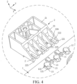
FIG. 4 is an exploded schematic diagram of the output electrode base and part of the support body according to some embodiments of the present disclosure. -
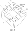
FIG. 5 is a schematic diagram of the output electrode base according to some embodiments of the present disclosure. -
FIG. 6 is a schematic diagram of the output electrode base, a busbar, and part of the support body according to some embodiments of the present disclosure. -
FIG. 7 is an exploded diagram of another output electrode base and part of another support body according to some other embodiments of the present disclosure. - 1, support body; 11, snap; 12, guide bump; 121, bump body; 122, limiting plate; 13, machining hole; 2, output electrode base; 21, base body; 22, mounting plate; 221, first side surface; 222, second side surface; 223 third side surface; 224, guide groove; 225, groove; 2251, first groove; 2252, second groove; 23, reinforcing plate; 24, insert nut; 3, output electrode protective cover; 4, series busbar; 41, output electrode piece.
- Some embodiments of the present disclosure will be described in detail below in connection with the accompanying drawings. The embodiments are described for illustrative purposes only and are not intended to limit the present disclosure.
- The terminology used herein is for the purpose of describing particular example embodiments only and is not intended to be limiting. As used herein, the singular forms "a," "an," and "the" may be intended to include the plural forms as well, unless the context clearly indicates otherwise.
- In the description of the present disclosure, it should be noted that unless otherwise explicitly specified and limited terms "connect" and "fix" should be understood in a broad sense. For example, a connection may be a fixed connection, a detachable connection, or an integral connection; may be a mechanical connection or an electrical connection; or may be a direct connection, an indirect connection through an intermediate medium, internal communication between two elements, or an interaction relationship between two elements. A person of ordinary skill in the art can understand specific meanings of the terms in the present present disclosure according to specific situations.
- As shown in
FIG. 1 to FIG. 3 andFIG. 6 , a cells contact system (CCS) assembly provided by the present disclosure includes asupport body 1, anoutput electrode base 2, and a connection assembly. Thesupport body 1 and theoutput electrode base 2 are insulating members. Thesupport body 1 is configured to support abusbar 4. Theoutput electrode base 2 is configured to be connected to anoutput electrode piece 41 of thebusbar 4. Theoutput electrode base 2 is further configured to be connected to an output electrodeprotective cover 3. Theoutput electrode base 2 is mounted to thesupport body 1 through the connection assembly. In some embodiments, thesupport body 1 and theoutput electrode base 2 are two independent components, so that thesupport body 1 and theoutput electrode base 2 independent of each other may be processed separately. Corresponding materials may be respectively selected to form thesupport body 1 andoutput electrode base 2 as required, so that problems such as softening and melting of thesupport body 1 and theoutput electrode base 2 during use are avoided, and a manufacturing difficulty can be reduced. The connection assembly may mount and connect thesupport body 1 and theoutput electrode base 2 to implement functions of the CCS assembly. - In some embodiments, the CCS assembly is applied to a battery module. An
insert nut 24 is arranged on theoutput electrode base 2. Theinsert nut 24 is fixed to theoutput electrode piece 41 of thebusbar 4 by a bolt. Theoutput electrode piece 41 of thebusbar 4 aggregates and outputs current of six parallel branches of cells in the battery module. Therefore, a temperature rise in an area of theoutput electrode base 2 is relatively high, and a temperature resistance requirement of a material required by theoutput electrode base 2 is relatively high. Optionally, theoutput electrode base 2 is injection-molded from a polybutylene terephthalate (PBT) +30% glass fiber (GF) material having a thermal deformation temperature up to 200°C. In some embodiments, a size of thesupport body 1 is relatively large, and a temperature rise of thesupport body 1 is much smaller than that of theoutput electrode base 2. To reduce a filling pressure of the injection molding, thesupport body 1 is injection-molded from a polycarbonate (PC) + acrylonitrile butadiene styrene (ABS) material having a thermal deformation temperature up to 105°C. - In some embodiments, the
output electrode base 2 is detachably connected to thesupport body 1 through the connection assembly. It may be understood that parts are worn during long-term use. A detachable connection between theoutput electrode base 2 and thesupport body 1 facilitate replacement of the parts and maintenance of the battery module. - In some alternative embodiments, the
output electrode base 2 may also be fixedly connected to thesupport body 1. For example, theoutput electrode base 2 and thesupport body 1 may be fixed together by a hot riveting process. In this case, the connection assembly is a rivet and a hole structure matched with the rivet. An insulating material may be used to manufacture the rivet. Since the materials of theoutput electrode base 2 and thesupport body 1 are different, theoutput electrode base 2 and thesupport body 1 have different melting points and injection molding temperatures. In some alternative embodiments, theoutput electrode base 2 may be formed first, and a hole or groove structure may be reserved on theoutput electrode base 2, theoutput electrode base 2 is putted into a mold of thesupport body 1, and then a material is injected into the mold to form thesupport body 1. Since the material of thesupport body 1 has good fluidity, the injected material may enter the reserved the hole or groove structure on theoutput electrode base 2. After curing and cooling, thesupport body 1 and theoutput electrode base 2 are fixed. It may be understood that the melting point of the material of theoutput electrode base 2 is high, and theoutput electrode base 2 will not be melted during the injection molding of thesupport body 1. That is, in some embodiments, the connection assembly include the hole or groove structure provided on theoutput electrode base 2 and a part of thesupport body 1 that flows into the hole or groove structure when thesupport body 1 is injection-molded. - In some embodiments, the connection assembly includes a
snap 11 and agroove 225. One of thesnap 11 and thegroove 225 is arranged on thesupport body 1, the other of thesnap 11 and thegroove 225 is arranged on theoutput electrode base 2. Thesnap 11 is engaged in thegroove 225. Thesnap 11 and thegroove 225 are arranged to fix thesupport body 1 and theoutput electrode base 2 in a snap-fit manner, which may facilitate the fixing and mounting of thesupport body 1 and theoutput electrode base 2. Thesnap 11 and thegroove 225 are formed directly on thesupport body 1 and theoutput electrode base 2, which may reduce a number of parts and simplify mounting steps. In some alternative embodiments, thesupport body 1 and theoutput electrode base 2 may also be fixed by a screw. In this case, one of theoutput electrode base 2 and thesupport body 1 is provided with a guide groove, the other of theoutput electrode base 2 and thesupport body 1 is provided with a guide bump. The screw is screwed into a threaded hole through the through hole. The screw requires to be insulated. In some embodiments, the connection assembly includes the screw, the through hole, and the treaded hole. In some embodiments, the screw may be replaced with a bolt and a fixing nut. - In some embodiments, the
snap 11 is inserted into thegroove 225 in a first direction. The connection assembly further includes aguide groove 224 and aguide bump 12. One of theoutput electrode base 2 and thesupport body 1 is provided with theguide groove 224, the other of theoutput electrode base 2 and thesupport body 1 is provided with theguide bump 12. Theguide bump 12 is slidably arranged in theguide groove 224. That is to say, theguide bump 12 is slidably arranged along a lengthwise direction of theguide groove 224, and a length of theguide groove 224 extends in the first direction. Theguide groove 224 may position theoutput electrode base 2 and thesupport body 1 for mounting, which further facilitates fixing and mounting thereof. Referring toFIG. 3 , the first direction corresponds to an X direction in the figure, a second direction corresponds to a Y direction in the figure, and a third direction corresponds to a Z direction in the figure. In some embodiments, theguide groove 224 and theguide bump 12 may limit theoutput electrode base 2 in the second direction and the third direction. - Further, in some embodiments, the
output electrode base 2 includes abase body 21 and a mountingplate 22. The mountingplate 22 has afirst side surface 221 and asecond side surface 222 connected to the first side surface to form an angle. Thefirst side surface 221 is away from thebase body 21, thesecond side surface 222 is connected to thebase body 21, and thefirst side surface 221 is provided with theguide groove 224 and thegroove 225 in a recessed manner. It may be understood that the mountingplate 22 is a plate structure, and the two groove structures of theguide groove 224 and thegroove 225 are both arranged on the mountingplate 22, which can reduce processing difficulty. - Referring to
FIG. 3 andFIG. 4 , optionally, theoutput electrode base 2 further includes a reinforcingplate 23. The reinforcingplate 23 is connected to thebase body 21 and thesecond side surface 222. It may be understood that the mountingplate 22 is of a cantilever structure. The two groove structures of theguide groove 224 and thegroove 225 arranged on the mountingplate 22 weaken strength of the mountingplate 22. The reinforcingplate 23 may improve a connecting strength between the mountingplate 22 and thebase body 21, and may also improve s strength of the mountingplate 22. In some embodiments, the CCS assembly includes six reinforcingplates 23, threeguide grooves 224, and twogrooves 225. Theguide grooves 224 and thegrooves 225 are respectively arranged in five gaps formed by the six reinforcingplates 23. Thegrooves 225 are located between twoadjacent guide grooves 224. - Referring to
FIG. 3 to FIG. 5 , in some embodiments, the mountingplate 22 has athird side surface 223 parallel to thesecond side surface 222. Theguide groove 224 extends through thesecond side surface 222 and thethird side surface 223. Theguide bump 12 includes abump body 121. One side of thebump body 121 is connected to thesupport body 1, and another side of thebump body 121 is provided with a limitingplate 122. Thebump body 121 is slidably arranged in theguide groove 224, the limitingplate 122 abuts against thesecond side surface 222, and thesupport body 1 abuts against thethird side surface 223. By arranging theguide groove 224 through thesecond side surface 222 and thethird side surface 223, theguide groove 224 is equivalent to a notch structure arranged on the mountingplate 22, which may reduce processing difficulty of theguide groove 224. In some embodiments, theoutput electrode base 2 is injection-molded, and the notch-shapedguide groove 224 may reduce design difficulty of the mold and reduce the cost. Since theguide groove 224 extends through thesecond side surface 222 of the mountingplate 22, theoutput electrode base 2 lacks a limit in the Z direction. Therefore, the limitingplate 122 may enable the mountingplate 22 to be clamped between thesupport body 1 and the limitingplate 122 to ensure connection stability between theoutput electrode base 2 and thesupport body 1. - Referring to
FIG. 7 , in some alternative embodiments, theguide groove 224 may not extend through thesecond side surface 222 and thethird side surface 223. In this case, theguide bump 12 may be of an L-shaped structure. An end of theguide bump 12 is connected with thesupport body 1 in the third direction, and the other end of theguide bump 12 is inserted into theguide groove 224 in the first direction. - Referring to
FIG. 3 andFIG. 4 , when thesnap 11 is engaged in thegroove 225, theguide bump 12 abuts against a groove wall of an end of theguide groove 224, which may also limit movement of theoutput electrode base 2 in the first direction, thereby further improving stability of fixing of theoutput electrode base 2. - Further, the
groove 225 includes a first groove 2251 and a second groove 2252 connected to the first groove 2251 to from an angle. Thefirst side surface 221 is provided with the first groove 2251 in a recessed manner. The second groove 2252 is arranged on a groove wall of the first groove 2251 and extends through thesecond side surface 222. An engagement position of thesnap 11 is engaged in the second groove 2252, and thesnap 11 abuts against a groove wall of the second groove 2252. By arranging the second groove 2252 extending through thesecond side surface 222, the processing difficulty of theoutput electrode base 2 may be reduced, thereby reducing the processing cost. Theguide groove 224 extends through thesecond side surface 222 and thethird side surface 223. Therefore, by setting the second groove 2252 extending through thesecond side surface 222, an opening direction on the mountingplate 22 may be consistent, which may also reduce difficulty of the mold design and reduce the production cost. - In some embodiments, a
machining hole 13 corresponding to each of thesnap 11 and theguide bump 12 is arranged on thesupport body 1. Since thesupport body 1 is injection-molded, themachining hole 13 may reduce a number of sliders in the mold, thereby reducing the difficulty of the mold design and reducing the cost. - Some embodiments further provide a battery module, which includes a cell and the CCS assembly as described in any one of the above embodiments. The cell is electrically connected to the
busbar 4 of the CCS assembly. Thesupport body 1 and theoutput electrode base 2 of the CCS assembly in the above embodiments have good molding quality and low processing difficulty. Therefore, the battery module including the CCS assembly has good quality and low processing cost. - In the description of the present disclosure, it should be understood that orientation or position relationships indicated by the terms such as "on", "below", "top", "left", and "right" are based on orientation or position relationships shown in the accompanying drawings, and are used only for ease and brevity of illustration and description of the operation, rather than indicating or implying that the mentioned apparatus or component need to have a particular orientation or need to be constructed and operated in a particular orientation. Therefore, such terms should not be construed as limiting of the present disclosure. In addition, terms "first" and "second" are only used for distinguishing between descriptions and have no special meaning.
- In the description of this specification, description such as "an embodiment" or "an example", means specific features, structures, materials, or features described in the embodiment or example are included in at least one embodiment or example of the present disclosure. In this specification, exemplary descriptions of the foregoing terms do not necessarily refer to the same embodiment or example.
- In addition, it should be understood that although this specification is described according to each implementation, each implementation may not include only one independent technical solution. The description manner of this specification is merely for clarity. This specification should be considered as a whole by a person skilled in the art, and the technical solution in each embodiment may also be properly combined, to form other implementations that can be understood by the person skilled in the art.
- The technical principle of the present disclosure has been described above in conjunction with specific embodiments. These descriptions are only for explaining the principle of the present disclosure, and cannot be construed in any way as limiting the protection scope of the present disclosure. Based on the explanation herein, a person skilled in the art can associate other specific embodiments of the present disclosure without creative effort, and these manners all fall within the protection scope of the present disclosure.
Claims (15)
- A cells contact system (CCS) assembly, comprising a support body (1), an output electrode base (2), and a connection assembly, wherein the support body (1) and the output electrode base (2) are insulating members, the support body (1) is configured to support a busbar (4), the output electrode base (2) is mounted to the support body (1) through the connection assembly, and the output electrode base (2) is configured to be connected to an output electrode piece (41) of the busbar (4).
- The CCS assembly as claimed in claim 1, wherein the output electrode base (2) is detachably connected to the support body (1) through the connection assembly.
- The CCS assembly as claimed in claim 1 or 2, wherein the connection assembly comprises a snap (11) and a groove (225), one of the snap (11) and the groove (225) is arranged on the support body (1), the other of the snap (11) and the groove (225) is arranged on the output electrode base (2), and the snap (11) is engaged in the groove (225).
- The CCS assembly as claimed in claim 3, wherein the snap (11) is inserted into the groove (225) in a first direction, the connection assembly further comprises a guide groove (224) and a guide bump (12), one of the output electrode base (2) and the support body (1) is provided with the guide groove (224), the other of the output electrode base (2) and the support body (1) is provided with the guide bump (12), the guide bump (12) is slidably arranged along the guide groove (224), and a length of the guide groove (224) extends in the first direction.
- The CCS assembly as claimed in claim 4, wherein the output electrode base (2) comprises a base body (21) and a mounting plate (22), the mounting plate (22) has a first side surface (221) and a second side surface (222) connected to the first side surface (221) to form an angle, the first side surface (221) is away from the base body (21), the second side surface (222) is connected to the base body (21), and the first side surface (221) is provided with the guide groove (224) and the groove (225) in a recessed manner.
- The CCS assembly as claimed in claim 5, wherein the mounting plate (22) has a third side surface (223) parallel to the second side surface (222), and the guide groove (224) extends through the second side surface (222) and the third side surface (223);
the guide bump (12) comprises a bump body (121), one side of the bump body (121) is connected to the support body (1), and another side of the bump body (121) is provided with a limiting plate (122), the bump body (121) is slidably arranged in the guide groove (224), the limiting plate (122) abuts against the second side surface (222), and the support body (1) abuts against the third side surface (223). - The CCS assembly as claimed in claim 5, wherein the guide bump (12) is of an L-shaped structure, an end of the guide bump (12) is connected with the support body (1), and another end of the guide bump (12) is inserted into the guide groove (224) in the first direction.
- The CCS assembly as claimed in claim 5, wherein when the snap (11) is engaged in the groove (225), the guide bump (12) abuts against a groove wall of an end of the guide groove (224).
- The CCS assembly as claimed in claim 5, wherein the groove (225) comprises a first groove (2251) and a second groove (2252) connected to the first groove (2251) to from an angle, the first side surface (221) is provided with the first groove (2251) in a recessed manner, the second groove (2252) is arranged on a groove wall of the first groove (2251) and extends through the second side surface (222), an engagement position of the snap (11) is engaged in the second groove (2252), and the snap (11) abuts against a groove wall of the second groove (2252).
- The CCS assembly as claimed in claim 5, wherein the output electrode base (2) further comprises a reinforcing plate (23), and the reinforcing plate (23) is connected to the base body (21) and the second side surface (222).
- A battery module, comprising a cells contact system (CCS) assembly and a cell, wherein the CCS assembly comprises: a support body (1), an output electrode base (2), and a connection assembly, wherein the support body (1) and the output electrode base (2) are insulating members, the support body (1) is configured to support a busbar (4), the output electrode base (2) is mounted to the support body (1) through the connection assembly, and the output electrode base (2) is configured to be connected to an output electrode piece (41) of the busbar (4);
wherein the cell is electrically connected to the busbar (4) of the CCS assembly. - The battery module as claimed in claim 11, wherein the output electrode base (2) is detachably connected to the support body (1) through the connection assembly.
- The battery module as claimed in claim 11, wherein the connection assembly comprises a snap (11) and a groove (225), one of the snap (11) and the groove (225) is arranged on the support body (1), the other of the snap (11) and the groove (225) is arranged on the output electrode base (2), and the snap (11) is engaged in the groove (225).
- The battery module as claimed in claim 13, wherein the snap (11)is inserted into the groove (225) in a first direction, the connection assembly further comprises a guide groove (224) and a guide bump (12), one of the output electrode base (2) and the support body (1) is provided with the guide groove (224), the other of the output electrode base (2) and the support body (1) is provided with the guide bump (12), the guide bump (12) is slidably arranged along the guide groove (224), and a length of the guide groove (224) extends in the first direction.
- The battery module as claimed in claim 14, wherein the output electrode base (2) comprises a base body (21) and a mounting plate (22), the mounting plate (22) has a first side surface (221) and a second side surface (222) connected to the first side surface (221) to form an angle, the first side surface (221) is away from the base body (21), the second side surface (222) is connected to the base body (21), and the first side surface (221) is provided with the guide groove (224) and the groove (225) in a recessed manner.
Applications Claiming Priority (1)
| Application Number | Priority Date | Filing Date | Title |
|---|---|---|---|
| CN202320638230.5U CN219959509U (en) | 2023-03-27 | 2023-03-27 | CCS assembly and battery module |
Publications (1)
| Publication Number | Publication Date |
|---|---|
| EP4439818A1 true EP4439818A1 (en) | 2024-10-02 |
Family
ID=88236677
Family Applications (1)
| Application Number | Title | Priority Date | Filing Date |
|---|---|---|---|
| EP23199648.9A Pending EP4439818A1 (en) | 2023-03-27 | 2023-09-26 | Ccs assemblies and battery modules |
Country Status (3)
| Country | Link |
|---|---|
| US (1) | US20240332749A1 (en) |
| EP (1) | EP4439818A1 (en) |
| CN (1) | CN219959509U (en) |
Families Citing this family (4)
| Publication number | Priority date | Publication date | Assignee | Title |
|---|---|---|---|---|
| USD1065069S1 (en) * | 2022-07-08 | 2025-03-04 | Eve Energy Co., Ltd. | Voltage and temperature collecting assembly for power battery |
| USD1115701S1 (en) * | 2022-07-08 | 2026-03-03 | Eve Energy Co., Ltd. | Voltage and temperature collecting assembly for power battery |
| USD1086053S1 (en) * | 2022-10-12 | 2025-07-29 | Eve Energy Co., Ltd. | Voltage and temperature collecting board for battery module |
| USD1087038S1 (en) * | 2022-11-07 | 2025-08-05 | Eve Energy Co., Ltd. | Battery module assembly |
Citations (3)
| Publication number | Priority date | Publication date | Assignee | Title |
|---|---|---|---|---|
| US20220006160A1 (en) * | 2020-07-03 | 2022-01-06 | Molex, Llc | Battery connection module |
| US20220069424A1 (en) * | 2020-08-27 | 2022-03-03 | Molex, Llc | Battery connection module |
| US20220140446A1 (en) * | 2020-11-02 | 2022-05-05 | Huizhou Poypow Technology Co., Ltd | Positive-and-negative electrode fixture of battery modules |
-
2023
- 2023-03-27 CN CN202320638230.5U patent/CN219959509U/en active Active
- 2023-09-26 EP EP23199648.9A patent/EP4439818A1/en active Pending
- 2023-09-26 US US18/474,296 patent/US20240332749A1/en active Pending
Patent Citations (3)
| Publication number | Priority date | Publication date | Assignee | Title |
|---|---|---|---|---|
| US20220006160A1 (en) * | 2020-07-03 | 2022-01-06 | Molex, Llc | Battery connection module |
| US20220069424A1 (en) * | 2020-08-27 | 2022-03-03 | Molex, Llc | Battery connection module |
| US20220140446A1 (en) * | 2020-11-02 | 2022-05-05 | Huizhou Poypow Technology Co., Ltd | Positive-and-negative electrode fixture of battery modules |
Also Published As
| Publication number | Publication date |
|---|---|
| US20240332749A1 (en) | 2024-10-03 |
| CN219959509U (en) | 2023-11-03 |
Similar Documents
| Publication | Publication Date | Title |
|---|---|---|
| EP4439818A1 (en) | Ccs assemblies and battery modules | |
| CN106058112B (en) | Cylindrical battery module | |
| EP3637503A1 (en) | Battery module comprising bus bar assembly | |
| CN102272976B (en) | Spacer for battery pack and battery pack including same | |
| CN114566764A (en) | Busbar subassembly and big cylinder power battery module | |
| KR102848633B1 (en) | Busbar assembly and cylindrical power battery module | |
| CN209029462U (en) | A kind of battery pack busbar and battery pack | |
| EP4456309A1 (en) | Ccs assembly, battery module and battery pack | |
| CN219801127U (en) | Battery module | |
| CN116937076A (en) | CCS assembly and battery module | |
| CN221353101U (en) | CCS assembly, battery module and battery | |
| CN215768925U (en) | Lithium battery acquisition unit | |
| CN220692271U (en) | CCS assembly and battery module | |
| CN113764809A (en) | Composite end plate, battery module comprising same and energy storage equipment | |
| CN222530746U (en) | Busbar and battery pack | |
| WO2024198045A1 (en) | Battery module | |
| EP3514004B1 (en) | Battery module and battery pack including same | |
| CN219040671U (en) | CCS structure for extremely simple battery module | |
| CN210183024U (en) | Probe substrate, battery charging module and battery charging device | |
| CN116315376A (en) | battery module | |
| CN202050001U (en) | Explosion-proof power battery of injection molding fixed electrode | |
| US20250070399A1 (en) | CCS Assembly and Battery Module | |
| CN223566680U (en) | An NTC mounting structure for use in energy storage batteries and power batteries | |
| CN223993371U (en) | Converging component and battery module | |
| CN219067149U (en) | Battery packs and battery packs |
Legal Events
| Date | Code | Title | Description |
|---|---|---|---|
| PUAI | Public reference made under article 153(3) epc to a published international application that has entered the european phase |
Free format text: ORIGINAL CODE: 0009012 |
|
| STAA | Information on the status of an ep patent application or granted ep patent |
Free format text: STATUS: REQUEST FOR EXAMINATION WAS MADE |
|
| 17P | Request for examination filed |
Effective date: 20230926 |
|
| AK | Designated contracting states |
Kind code of ref document: A1 Designated state(s): AL AT BE BG CH CY CZ DE DK EE ES FI FR GB GR HR HU IE IS IT LI LT LU LV MC ME MK MT NL NO PL PT RO RS SE SI SK SM TR |