EP4439816A1 - Battery module, battery pack, and vehicle - Google Patents
Battery module, battery pack, and vehicle Download PDFInfo
- Publication number
- EP4439816A1 EP4439816A1 EP23765984.2A EP23765984A EP4439816A1 EP 4439816 A1 EP4439816 A1 EP 4439816A1 EP 23765984 A EP23765984 A EP 23765984A EP 4439816 A1 EP4439816 A1 EP 4439816A1
- Authority
- EP
- European Patent Office
- Prior art keywords
- sampling
- battery
- battery core
- housing
- battery module
- Prior art date
- Legal status (The legal status is an assumption and is not a legal conclusion. Google has not performed a legal analysis and makes no representation as to the accuracy of the status listed.)
- Pending
Links
Images




Classifications
-
- H—ELECTRICITY
- H01—ELECTRIC ELEMENTS
- H01M—PROCESSES OR MEANS, e.g. BATTERIES, FOR THE DIRECT CONVERSION OF CHEMICAL ENERGY INTO ELECTRICAL ENERGY
- H01M10/00—Secondary cells; Manufacture thereof
- H01M10/42—Methods or arrangements for servicing or maintenance of secondary cells or secondary half-cells
- H01M10/425—Structural combination with electronic components, e.g. electronic circuits integrated to the outside of the casing
-
- H—ELECTRICITY
- H01—ELECTRIC ELEMENTS
- H01M—PROCESSES OR MEANS, e.g. BATTERIES, FOR THE DIRECT CONVERSION OF CHEMICAL ENERGY INTO ELECTRICAL ENERGY
- H01M50/00—Constructional details or processes of manufacture of the non-active parts of electrochemical cells other than fuel cells, e.g. hybrid cells
- H01M50/50—Current conducting connections for cells or batteries
- H01M50/569—Constructional details of current conducting connections for detecting conditions inside cells or batteries, e.g. details of voltage sensing terminals
-
- H—ELECTRICITY
- H01—ELECTRIC ELEMENTS
- H01M—PROCESSES OR MEANS, e.g. BATTERIES, FOR THE DIRECT CONVERSION OF CHEMICAL ENERGY INTO ELECTRICAL ENERGY
- H01M10/00—Secondary cells; Manufacture thereof
- H01M10/42—Methods or arrangements for servicing or maintenance of secondary cells or secondary half-cells
- H01M10/48—Accumulators combined with arrangements for measuring, testing or indicating the condition of cells, e.g. the level or density of the electrolyte
-
- H—ELECTRICITY
- H01—ELECTRIC ELEMENTS
- H01M—PROCESSES OR MEANS, e.g. BATTERIES, FOR THE DIRECT CONVERSION OF CHEMICAL ENERGY INTO ELECTRICAL ENERGY
- H01M10/00—Secondary cells; Manufacture thereof
- H01M10/42—Methods or arrangements for servicing or maintenance of secondary cells or secondary half-cells
- H01M10/48—Accumulators combined with arrangements for measuring, testing or indicating the condition of cells, e.g. the level or density of the electrolyte
- H01M10/482—Accumulators combined with arrangements for measuring, testing or indicating the condition of cells, e.g. the level or density of the electrolyte for several batteries or cells simultaneously or sequentially
-
- H—ELECTRICITY
- H01—ELECTRIC ELEMENTS
- H01M—PROCESSES OR MEANS, e.g. BATTERIES, FOR THE DIRECT CONVERSION OF CHEMICAL ENERGY INTO ELECTRICAL ENERGY
- H01M50/00—Constructional details or processes of manufacture of the non-active parts of electrochemical cells other than fuel cells, e.g. hybrid cells
- H01M50/20—Mountings; Secondary casings or frames; Racks, modules or packs; Suspension devices; Shock absorbers; Transport or carrying devices; Holders
- H01M50/204—Racks, modules or packs for multiple batteries or multiple cells
-
- H—ELECTRICITY
- H01—ELECTRIC ELEMENTS
- H01M—PROCESSES OR MEANS, e.g. BATTERIES, FOR THE DIRECT CONVERSION OF CHEMICAL ENERGY INTO ELECTRICAL ENERGY
- H01M50/00—Constructional details or processes of manufacture of the non-active parts of electrochemical cells other than fuel cells, e.g. hybrid cells
- H01M50/20—Mountings; Secondary casings or frames; Racks, modules or packs; Suspension devices; Shock absorbers; Transport or carrying devices; Holders
- H01M50/204—Racks, modules or packs for multiple batteries or multiple cells
- H01M50/207—Racks, modules or packs for multiple batteries or multiple cells characterised by their shape
- H01M50/209—Racks, modules or packs for multiple batteries or multiple cells characterised by their shape adapted for prismatic or rectangular cells
-
- H—ELECTRICITY
- H01—ELECTRIC ELEMENTS
- H01M—PROCESSES OR MEANS, e.g. BATTERIES, FOR THE DIRECT CONVERSION OF CHEMICAL ENERGY INTO ELECTRICAL ENERGY
- H01M50/00—Constructional details or processes of manufacture of the non-active parts of electrochemical cells other than fuel cells, e.g. hybrid cells
- H01M50/20—Mountings; Secondary casings or frames; Racks, modules or packs; Suspension devices; Shock absorbers; Transport or carrying devices; Holders
- H01M50/249—Mountings; Secondary casings or frames; Racks, modules or packs; Suspension devices; Shock absorbers; Transport or carrying devices; Holders specially adapted for aircraft or vehicles, e.g. cars or trains
-
- H—ELECTRICITY
- H01—ELECTRIC ELEMENTS
- H01M—PROCESSES OR MEANS, e.g. BATTERIES, FOR THE DIRECT CONVERSION OF CHEMICAL ENERGY INTO ELECTRICAL ENERGY
- H01M50/00—Constructional details or processes of manufacture of the non-active parts of electrochemical cells other than fuel cells, e.g. hybrid cells
- H01M50/50—Current conducting connections for cells or batteries
- H01M50/502—Interconnectors for connecting terminals of adjacent batteries; Interconnectors for connecting cells outside a battery casing
-
- H—ELECTRICITY
- H01—ELECTRIC ELEMENTS
- H01M—PROCESSES OR MEANS, e.g. BATTERIES, FOR THE DIRECT CONVERSION OF CHEMICAL ENERGY INTO ELECTRICAL ENERGY
- H01M50/00—Constructional details or processes of manufacture of the non-active parts of electrochemical cells other than fuel cells, e.g. hybrid cells
- H01M50/50—Current conducting connections for cells or batteries
- H01M50/502—Interconnectors for connecting terminals of adjacent batteries; Interconnectors for connecting cells outside a battery casing
- H01M50/509—Interconnectors for connecting terminals of adjacent batteries; Interconnectors for connecting cells outside a battery casing characterised by the type of connection, e.g. mixed connections
- H01M50/51—Connection only in series
-
- H—ELECTRICITY
- H01—ELECTRIC ELEMENTS
- H01M—PROCESSES OR MEANS, e.g. BATTERIES, FOR THE DIRECT CONVERSION OF CHEMICAL ENERGY INTO ELECTRICAL ENERGY
- H01M50/00—Constructional details or processes of manufacture of the non-active parts of electrochemical cells other than fuel cells, e.g. hybrid cells
- H01M50/50—Current conducting connections for cells or batteries
- H01M50/502—Interconnectors for connecting terminals of adjacent batteries; Interconnectors for connecting cells outside a battery casing
- H01M50/514—Methods for interconnecting adjacent batteries or cells
- H01M50/516—Methods for interconnecting adjacent batteries or cells by welding, soldering or brazing
-
- H—ELECTRICITY
- H01—ELECTRIC ELEMENTS
- H01M—PROCESSES OR MEANS, e.g. BATTERIES, FOR THE DIRECT CONVERSION OF CHEMICAL ENERGY INTO ELECTRICAL ENERGY
- H01M50/00—Constructional details or processes of manufacture of the non-active parts of electrochemical cells other than fuel cells, e.g. hybrid cells
- H01M50/50—Current conducting connections for cells or batteries
- H01M50/502—Interconnectors for connecting terminals of adjacent batteries; Interconnectors for connecting cells outside a battery casing
- H01M50/519—Interconnectors for connecting terminals of adjacent batteries; Interconnectors for connecting cells outside a battery casing comprising printed circuit boards [PCB]
-
- H—ELECTRICITY
- H01—ELECTRIC ELEMENTS
- H01M—PROCESSES OR MEANS, e.g. BATTERIES, FOR THE DIRECT CONVERSION OF CHEMICAL ENERGY INTO ELECTRICAL ENERGY
- H01M50/00—Constructional details or processes of manufacture of the non-active parts of electrochemical cells other than fuel cells, e.g. hybrid cells
- H01M50/50—Current conducting connections for cells or batteries
- H01M50/543—Terminals
-
- H—ELECTRICITY
- H01—ELECTRIC ELEMENTS
- H01M—PROCESSES OR MEANS, e.g. BATTERIES, FOR THE DIRECT CONVERSION OF CHEMICAL ENERGY INTO ELECTRICAL ENERGY
- H01M50/00—Constructional details or processes of manufacture of the non-active parts of electrochemical cells other than fuel cells, e.g. hybrid cells
- H01M50/50—Current conducting connections for cells or batteries
- H01M50/543—Terminals
- H01M50/547—Terminals characterised by the disposition of the terminals on the cells
- H01M50/548—Terminals characterised by the disposition of the terminals on the cells on opposite sides of the cell
-
- H—ELECTRICITY
- H01—ELECTRIC ELEMENTS
- H01M—PROCESSES OR MEANS, e.g. BATTERIES, FOR THE DIRECT CONVERSION OF CHEMICAL ENERGY INTO ELECTRICAL ENERGY
- H01M50/00—Constructional details or processes of manufacture of the non-active parts of electrochemical cells other than fuel cells, e.g. hybrid cells
- H01M50/50—Current conducting connections for cells or batteries
- H01M50/543—Terminals
- H01M50/564—Terminals characterised by their manufacturing process
- H01M50/566—Terminals characterised by their manufacturing process by welding, soldering or brazing
-
- H—ELECTRICITY
- H01—ELECTRIC ELEMENTS
- H01M—PROCESSES OR MEANS, e.g. BATTERIES, FOR THE DIRECT CONVERSION OF CHEMICAL ENERGY INTO ELECTRICAL ENERGY
- H01M50/00—Constructional details or processes of manufacture of the non-active parts of electrochemical cells other than fuel cells, e.g. hybrid cells
- H01M50/50—Current conducting connections for cells or batteries
- H01M50/572—Means for preventing undesired use or discharge
- H01M50/574—Devices or arrangements for the interruption of current
- H01M50/583—Devices or arrangements for the interruption of current in response to current, e.g. fuses
-
- H—ELECTRICITY
- H01—ELECTRIC ELEMENTS
- H01M—PROCESSES OR MEANS, e.g. BATTERIES, FOR THE DIRECT CONVERSION OF CHEMICAL ENERGY INTO ELECTRICAL ENERGY
- H01M10/00—Secondary cells; Manufacture thereof
- H01M10/42—Methods or arrangements for servicing or maintenance of secondary cells or secondary half-cells
- H01M10/425—Structural combination with electronic components, e.g. electronic circuits integrated to the outside of the casing
- H01M2010/4271—Battery management systems including electronic circuits, e.g. control of current or voltage to keep battery in healthy state, cell balancing
-
- H—ELECTRICITY
- H01—ELECTRIC ELEMENTS
- H01M—PROCESSES OR MEANS, e.g. BATTERIES, FOR THE DIRECT CONVERSION OF CHEMICAL ENERGY INTO ELECTRICAL ENERGY
- H01M2200/00—Safety devices for primary or secondary batteries
- H01M2200/10—Temperature sensitive devices
- H01M2200/103—Fuse
-
- H—ELECTRICITY
- H01—ELECTRIC ELEMENTS
- H01M—PROCESSES OR MEANS, e.g. BATTERIES, FOR THE DIRECT CONVERSION OF CHEMICAL ENERGY INTO ELECTRICAL ENERGY
- H01M2220/00—Batteries for particular applications
- H01M2220/20—Batteries in motive systems, e.g. vehicle, ship, plane
-
- Y—GENERAL TAGGING OF NEW TECHNOLOGICAL DEVELOPMENTS; GENERAL TAGGING OF CROSS-SECTIONAL TECHNOLOGIES SPANNING OVER SEVERAL SECTIONS OF THE IPC; TECHNICAL SUBJECTS COVERED BY FORMER USPC CROSS-REFERENCE ART COLLECTIONS [XRACs] AND DIGESTS
- Y02—TECHNOLOGIES OR APPLICATIONS FOR MITIGATION OR ADAPTATION AGAINST CLIMATE CHANGE
- Y02E—REDUCTION OF GREENHOUSE GAS [GHG] EMISSIONS, RELATED TO ENERGY GENERATION, TRANSMISSION OR DISTRIBUTION
- Y02E60/00—Enabling technologies; Technologies with a potential or indirect contribution to GHG emissions mitigation
- Y02E60/10—Energy storage using batteries
Definitions
- the present disclosure relates to the technical field of battery structures, and specifically, the present disclosure relates to a battery module, a battery pack, and a vehicle.
- lithium ion batteries have the advantages of high working voltage, high specific energy, long cycle life, no environmental pollution, and the like, are not only widely applied to mobile communication devices and portable electronic devices, but also widely applied to large and medium-sized electric devices such as electric automobiles, electric bicycles, and electric tools, and are main directions of development for major battery manufacturers at present.
- Multiple battery cores are generally arranged inside a lithium ion battery.
- the battery core provided with terminals at two ends need to be sampled at both ends of the battery core, which increases structural complexity and structural cost of sampling.
- a housing of the battery core is generally not charged or has a low voltage, so that an electrolyte in the battery core easily corrodes the housing and assemblies on the housing, which easily causes a problem of electrolyte leakage of the battery core, and affects the use safety of the lithium ion battery.
- An objective of embodiments of the present disclosure is to provide a new technical solution of a battery module, a battery pack, and a vehicle.
- a battery module including:
- the sampling assembly includes a sampling portion.
- the sampling portion includes a sampling terminal and an output terminal.
- the sampling terminal is electrically connected to the housing and/or the connection sheet.
- welding portions are arranged on the housing.
- the sampling portion is electrically connected to the welding portions through the sampling terminal.
- the sampling terminal includes a first sampling terminal and a second sampling terminal.
- the first sampling terminal is electrically connected to the welding portions and one of the connection sheets.
- the second sampling terminal is electrically connected to another welding portion.
- the first sampling terminal includes a first connection segment and a second connection segment.
- the sampling portion is electrically connected to the welding portion through the first connection segment.
- the connection sheet is electrically connected to the welding portion through the second connection segment.
- the first sampling terminal is configured to collect information in the battery core by the sampling portion through the welding portion, and to apply a voltage to the housing through the connection sheet; and the second sampling terminal is configured collect the information in the battery core by the sampling portion through the welding portion.
- the sampling assembly includes a protection portion.
- One end of the protection portion is electrically connected to the sampling terminal and the welding portion, and the other end of the protection portion is connected to the connection sheet.
- sampling portion and the protection portion are at least one of a flexible printed circuit (FPC) or a printed circuit board (PCB).
- FPC flexible printed circuit
- PCB printed circuit board
- sampling portion (4) and the protection portion (5) are integrally formed.
- sampling portion is arranged at a top side of the battery core assembly, and the protection portion is arranged parallel to the sampling portion.
- sampling portion is perpendicular to the protection portion.
- the protection portion is arranged on one side of the battery core assembly provided with the terminal.
- the sampling portion is a first flexible connection member, and the first flexible connection member is inserted into and matches a sampler.
- the protection portion is a second flexible connection member, and a protection circuit connected to the connection sheet and the housing is arranged in the second flexible connection member.
- the protection circuit includes a fuse protector or a fuse wire.
- a frame is further included; and the multiple battery cores are arranged in the frame side by side.
- a battery pack including the battery module described in the first aspect.
- a vehicle including the battery module described in the first aspect or the battery pack described in the second aspect.
- the embodiments of the present disclosure provide a battery module.
- the battery module includes a battery core assembly and a sampling assembly. After a voltage is applied to the housing through the sampling assembly, that is, the housing has the voltage, the damage caused by infiltrating the housing by an electrolyte in the battery core can be reduced, the integrity and stability of the housing are ensured, and the use safety of the battery module is improved.
- the sampling portion may sample on a single side, which simplifies a structure of the sampling portion, and reduces the design cost of the sampling portion.
- the battery module 100 may be applied to a power battery of an electric vehicle.
- the battery module 100 includes: a battery core assembly and a sampling assembly.
- the sampling assembly is configured to sample battery core information of the battery core assembly, for example, sampling a temperature, a pressure, an electrolyte storage capacity, and the like of the battery core assembly, so as to ensure stable performance of the battery module 100.
- the battery core assembly includes multiple battery cores 2. Two opposite ends of the battery core 2 are provided with terminals. Positive and negative electrodes may sequentially alternate at one end of the multiple battery cores 2, and positive and negative electrodes may sequentially alternate at the other end of the multiple battery cores 2, so as to facilitate series connection of the multiple battery cores 2, as shown in FIG. 1 .
- the multiple battery cores 2 are sequentially connected in series through connection sheets 3. Two opposite ends of the battery core 2 are provided with the terminals, that is, the multiple connection sheets 3 are arranged at both ends of the battery core assembly.
- the battery core 2 includes a housing 21.
- An explosion-proof valve 22 may be arranged on the housing 21.
- the connection sheet 3 connected to a positive electrode of each battery core 2 is electrically connected to a housing 21 of the corresponding battery core 2 on a positive electrode side P of the battery core assembly.
- a portion on each connection sheet 3 electrically connected to a positive electrode of the battery core 2 is connected to the housing 21 of the corresponding battery core 2.
- connection sheet 3 applies a voltage to the housing 21 of the battery core 2, that is, the housing 21 and the explosion-proof valve 22 have the voltage, an electric potential of the housing 21 and the explosion-proof valve 22 is improved, and the housing 21 and the explosion-proof valve 22 are protected.
- the housing 21 on a negative electrode side N of the battery core assembly is electrically connected to the connection sheet 3 through the sampling assembly, so that the sampling portion 4 may protect the electric potential of the housing 21 on the basis of collecting the battery core information such as a temperature, a pressure, and an electrolyte storage capacity of each battery core 2.
- the multiple battery cores 2 are sequentially connected in series through the connection sheets 3, a total positive terminal and a total negative terminal directly connected to the outside may be formed.
- a side where the total positive terminal is located is the positive electrode side P of the battery core assembly, and a side where the total negative terminal is located is the negative electrode side N of the battery core assembly.
- the explosion-proof valve 22 may be made of a thin aluminum material. After a voltage is applied to the housing 21 through the connection sheet 3, that is, the explosion-proof valve 22 on the housing 21 has the voltage, the damage caused by infiltrating the housing 21 and the explosion-proof valve 22 by an electrolyte in the battery core 2 can be reduced, the integrity and stability of the housing 21 and the explosion-proof valve 22 are ensured, and the use safety of the battery module 100 is improved.
- the sampling assembly may sample on a single side, that is, the sampling assembly is only arranged on one side of the battery core assembly, which simplifies a structure of the sampling assembly, and reduces the design cost of the sampling assembly.
- the battery module 100 provided by the embodiments of the present disclosure includes a battery core assembly and a sampling assembly.
- the battery core assembly includes multiple battery cores 2. Two opposite ends of the battery core 2 are provided with the terminals.
- the multiple battery cores 2 are sequentially connected in series through connection sheets 3.
- the battery core 2 includes a housing 21.
- the connection sheet 3 connected to a positive electrode of each of the battery cores 2 is electrically connected to the housing 21 of the corresponding battery core 2.
- the sampling assembly includes a sampling portion 4.
- the sampling portion 4 includes a sampling terminal 41 and an output terminal 42.
- the sampling terminal 41 is electrically connected to the housing 21 and/or the connection sheet 3.
- the sampling portion 4 is electrically connected to the housing 21 through the sampling terminal 41, and the output terminal 42 is connected to an external sampling device, so as to collect and transmit the battery core information such as a temperature, a pressure, and an electrolyte storage capacity of the battery core 2 to an external sampling device, and then process and monitor the information to ensure operating stability of the battery module 100.
- the sampling terminal 41 is electrically connected to the connection sheet 3
- the housing 21 may be charged through the connection sheet 3, which ensures integrity and stability of the housing 21.
- welding portions 7 are arranged on the housing 21, and the sampling portion 4 is electrically connected to the welding portions 7 through the sampling terminal 41.
- one end of the sampling terminal 41 may overlap on a sampling main body of the sampling portion 4, and the other end or a middle position of the sampling terminal 41 may be welded on the welding portion 7 of the housing 21.
- the welding portion 7 may be specifically a welding spot set on the housing 21, so as to weld the sampling terminal 41 and the housing 21.
- the housing 21 may be electrically connected to the sampling portion 4 through the sampling terminal 41.
- the sampling terminal 41 includes a first sampling terminal 411 and a second sampling terminal 412.
- the first sampling terminal 411 is electrically connected to the welding portion 7 and the connection sheet 3.
- the second sampling terminal 412 is electrically connected to the welding portion 7.
- the welding portion 7 may be electrically connected to the connection sheet 3 through the first sampling terminal 411. That is, the first sampling terminal 411 can achieve collection of the information in the battery core 2 by the sampling portion 4 through the welding portion 7, and can apply the voltage to the housing 21 through the connection sheet 3. Part sampling terminals of the sampling terminals 41 only need to collect the information in the battery core 2, alternatively the second sampling terminal 412 may be connected to the welding portion 7 only. The second sampling terminal 412 achieves collection of the information in the battery core 2 by the sampling portion 4 through the welding portion 7, which simplifies a structure of the sampling terminal 41.
- the connection sheet 3 may be electrically connected to the housing 21 through an assembly provided with a protection circuit.
- the first sampling terminal 411 includes a first connection segment 411a and a second connection segment 411b, the sampling portion 4 is electrically connected to the welding portion 7 through the first connection segment 41 1a, and the connection sheet 3 is electrically connected to the welding portion 7 through the second connection segment 411b.
- the connection sheet 3 may apply a voltage to the housing 21 through the second connection segment 411b, and a safety circuit may be arranged on the second connection segment 411b.
- the first sampling terminal 411 is formed after the first connection segment 411a and the second connection segment 411b are integrally formed. One end of the first sampling terminal 411 is connected to the welding portion 7, and the other end of the first sampling terminal 411 is connected to the connection sheet 3. The middle position of the first sampling terminal 411 may be welded to the housing 21 of the battery core 2.
- voltage application to the housing 21 of the battery core 2 and the sampling of the sampling portion 4 may be achieved at the same time by only welding a middle part of the first sampling terminal 411 once, which simplifies a structure of the first sampling terminal 411 and reduces time cost of production.
- the sampling assembly includes a protection portion 5.
- One end of the protection portion 5 is electrically connected to the sampling terminal 41 and the welding portion 7, and the other end of the protection portion 5 is connected to the connection sheet 3.
- the protection portion 5 may be arranged between the connection sheet 3 and the welding portion 7 of the housing 21.
- the protection portion 5 may be specifically a fuse protector (a fuse protection circuit), a fuse wire, or the like, so as to ensure stability of the voltage on the housing 21.
- sampling portion 4 and the protection portion 5 are at least one of an FPC or a PCB.
- the sampling portion 4 and the protection portion 5 may be integrally formed into an assembly.
- the assembly may have an assembly substrate, for example, the assembly substrate may be a PCB substrate or a FPC substrate. Both the sampling portion 4 and the protection portion 5 may be formed on the assembly substrate, so as to improve the integrity and compactness of the sampling portion 4 and the protection portion 5.
- the sampling portion 4 and the protection portion 5 are PCBs or double-sided FPCs.
- the sampling portion 4 and the protection portion 5 may be formed on the PCB substrate together, so that the assembly forms the PCB.
- the PCB may be an integrated battery information collector (BIC).
- BIC Battery information collector
- the sampling portion 4 and the protection portion 5 may be two independent two FPCs respectively, referring to FIG. 4 to FIG. 9 .
- a circuit of the sampling portion 4 may be etched on one side of the FPC substrate, as shown in FIG. 7
- a circuit of the protection portion 5 may be etched on the other side of the FPC substrate, as shown in FIG. 8 , so as to form the double-sided FPC, as shown in FIG. 9 .
- the sampling portion 4 is arranged at a top side of the battery core assembly.
- the two opposite ends of the battery core 2 are provided with the terminals 23, the battery core 2 is transversely placed in a frame 1, and the top side of the battery core assembly has a flat top surface, so a width dimension of the sampling portion 4 (that is, a dimension in an extending direction of the battery core 2) is not affected by structures such as the terminals on a side surface of the battery core 2, and a height of the side surface of the battery core 2 will not affect the dimension of the sampling portion 4 when the sampling portion 4 is arranged at the top side of the battery core assembly.
- the width dimension of the sampling portion 4 may be flexibly adjusted. For example, a width of the sampling portion 4 may be made wider, such as a change of the sampling portion 4 in FIG. 8 relative to the sampling portion 4 in FIG. 7 , and a change of the sampling portion 4 in FIG. 10 relative to the sampling portion 4 in FIG. 9 , so as to meet a space required by wiring in the sampling portion 4.
- sampling portion 4 may not overlap with a high-voltage loop at an end portion of the battery core 2, which reduces a risk of the EMC of the sampling portion 4.
- the protection portion 5 is arranged at an end portion of the battery core assembly provided with the terminal 23.
- the two opposite ends of the battery core 2 are provided with the terminals 23, that is, the multiple connection sheets 3 are arranged at both ends of the battery core assembly.
- the protection portion 5 may be arranged at the end portion of the battery core assembly.
- the sampling portion 4 is arranged at the top side of the battery core assembly, and the sampling portion 4 and the protection portion 5 may form structures perpendicular to each other, so that the protection portion 5 and the connection sheet 3 are located at the same end of the battery core 2.
- the connection sheet 3 may be conveniently connected to the housing at a corresponding end of the battery core 2 through the protection portion 5 to simplify a structure of the protection portion 5.
- the protection portion 5 is arranged in parallel to the sampling portion 4.
- the protection portion 5 may be arranged in parallel to the sampling portion 4.
- the sampling portion 4 is arranged on the top side of the battery core assembly, that is, the protection portion 5 may alternatively be arranged at the top side of the battery core assembly or in a space higher than the battery core assembly, so as to ensure stable performance of the protection portion 5.
- the sampling portion 4 is a first flexible connection member, and the first flexible connection member is inserted into and matches the sampler 6 through a plug connector.
- the first flexible connection member may be an FPC, a flexible flat cable (FFC), or a flexible conductive cable (FDC), and a width of the first flexible connection member is adjustable.
- the sampler 6 may process the battery core information of each of the battery cores 2 collected by the first flexible connection member after the plug connector is inserted into and matches the sampler 6. Since the first flexible connection member has a flexible structure, a position and an extending direction of the first flexible connection member may be flexibly set, which improves the structural flexibility of the sampling portion 4.
- the protection portion 5 is a second flexible connection member, and a protection circuit connected to the connection sheet 3 and the housing 21 is arranged in the second flexible connection member.
- the second flexible connection member may be an FPC, an FFC, or an FDC.
- One end of the second flexible connection member may be electrically connected to the connection sheet 3, and the other end of the second flexible connection member may be connected to the housing 21, so as to apply a voltage to the housing 21 of the battery core 2 through the connection sheet 3.
- a protection circuit connected to the connection sheet 3 and the housing 21 may be arranged in the second flexible connection member.
- the protection circuit may be a fuse protector (a fuse protection circuit), a fuse wire, or the like, so as to ensure the structural integrity of the housing 21.
- the battery module 100 further includes a frame 1; and the multiple battery cores 2 are arranged in the frame 1 side by side.
- the frame 1 may include a lower plate 11, an upper plate 12, and side plates 13.
- the side plates 13 are connected between the lower plate 11 and the upper plate 12.
- the lower plate 11, the upper plate 12, and the side plates 13 form an accommodation cavity 14 in a manner of bonding, welding, or threaded connection.
- the battery core assembly is arranged in the accommodation cavity 14 in the frame 1.
- the frame 1 may provide support and protection for the battery core assembly.
- FIG. 11 is a schematic diagram of a battery pack according to an embodiment of the present disclosure.
- the present disclosure further provides a battery pack 200.
- the battery pack 200 includes at least one of the battery modules 100.
- the battery pack 200 may serve as a power battery of a vehicle.
- the battery module 100 includes a battery core assembly and a sampling assembly.
- the battery core assembly includes multiple battery cores 2. Two opposite ends of the battery core 2 are provided with terminals.
- the multiple battery cores 2 are sequentially connected in series through connection sheets 3.
- the battery core 2 includes a housing 21.
- the connection sheet 3 connected to a positive electrode of each of the battery cores 2 is electrically connected to the housing 21 of the corresponding battery core 2.
- the housing 21 After a voltage is applied to the housing 21 through the sampling assembly, that is, the housing 21 has the voltage, the damage caused by infiltrating the housing 21 by an electrolyte in the battery core 2 can be reduced, the integrity and stability of the housing 21 are ensured, and the use safety of the battery module 200 is improved.
- FIG. 12 is a schematic diagram of a vehicle according to an embodiment of the present disclosure.
- the embodiments of the present disclosure further provides a vehicle 300.
- the vehicle includes a battery pack 200. At least one of the battery modules 100 is arranged in the battery pack 200.
- the battery module 100 of the vehicle 300 includes a battery core assembly and a sampling assembly.
- the battery core assembly includes multiple battery cores 2. Two opposite ends of the battery core 2 are provided with terminals.
- the multiple battery cores 2 are sequentially connected in series through connection sheets 3.
- the battery core 2 includes a housing 21.
- the connection sheet 3 connected to a positive electrode of each of the battery cores 2 is electrically connected to the housing 21 of the corresponding battery core 2.
Landscapes
- Chemical & Material Sciences (AREA)
- Chemical Kinetics & Catalysis (AREA)
- Electrochemistry (AREA)
- General Chemical & Material Sciences (AREA)
- Engineering & Computer Science (AREA)
- Manufacturing & Machinery (AREA)
- Aviation & Aerospace Engineering (AREA)
- Microelectronics & Electronic Packaging (AREA)
- Battery Mounting, Suspending (AREA)
- Connection Of Batteries Or Terminals (AREA)
Abstract
Description
- The present disclosure claims priority to
Chinese Patent Application No. 202220482834.0 filed with the National Intellectual Property Administration on March 7, 2022 - The present disclosure relates to the technical field of battery structures, and specifically, the present disclosure relates to a battery module, a battery pack, and a vehicle.
- At present, lithium ion batteries have the advantages of high working voltage, high specific energy, long cycle life, no environmental pollution, and the like, are not only widely applied to mobile communication devices and portable electronic devices, but also widely applied to large and medium-sized electric devices such as electric automobiles, electric bicycles, and electric tools, and are main directions of development for major battery manufacturers at present.
- Multiple battery cores are generally arranged inside a lithium ion battery. The battery core provided with terminals at two ends need to be sampled at both ends of the battery core, which increases structural complexity and structural cost of sampling. Moreover, a housing of the battery core is generally not charged or has a low voltage, so that an electrolyte in the battery core easily corrodes the housing and assemblies on the housing, which easily causes a problem of electrolyte leakage of the battery core, and affects the use safety of the lithium ion battery.
- Therefore, it is necessary to improve a structure of the lithium ion battery to improve the overall safety performance of the lithium ion battery.
- An objective of embodiments of the present disclosure is to provide a new technical solution of a battery module, a battery pack, and a vehicle.
- According to a first aspect of the present disclosure, a battery module is provided, including:
- a battery core assembly, where the battery core assembly includes multiple battery cores, two opposite ends of each battery core of the multiple battery cores are provided with terminals, the multiple battery cores are sequentially connected in series through connection sheets, each battery core includes a housing, and the connection sheet connected to a positive electrode of each battery core is electrically connected to the housing of the corresponding battery core on a positive electrode side of the battery core assembly; and
- a sampling assembly, where the housing on a negative electrode side of the battery core assembly is electrically connected to the connection sheet through the sampling assembly.
- Optionally, the sampling assembly includes a sampling portion. The sampling portion includes a sampling terminal and an output terminal. The sampling terminal is electrically connected to the housing and/or the connection sheet.
- Optionally, welding portions are arranged on the housing. The sampling portion is electrically connected to the welding portions through the sampling terminal.
- Optionally, the sampling terminal includes a first sampling terminal and a second sampling terminal. The first sampling terminal is electrically connected to the welding portions and one of the connection sheets. The second sampling terminal is electrically connected to another welding portion.
- Optionally, the first sampling terminal includes a first connection segment and a second connection segment. The sampling portion is electrically connected to the welding portion through the first connection segment. The connection sheet is electrically connected to the welding portion through the second connection segment.
- Optionally, the first sampling terminal is configured to collect information in the battery core by the sampling portion through the welding portion, and to apply a voltage to the housing through the connection sheet; and
the second sampling terminal is configured collect the information in the battery core by the sampling portion through the welding portion. - Optionally, the sampling assembly includes a protection portion. One end of the protection portion is electrically connected to the sampling terminal and the welding portion, and the other end of the protection portion is connected to the connection sheet.
- Optionally, the sampling portion and the protection portion are at least one of a flexible printed circuit (FPC) or a printed circuit board (PCB).
- Optionally, the sampling portion (4) and the protection portion (5) are integrally formed. Optionally, the sampling portion is arranged at a top side of the battery core assembly, and the protection portion is arranged parallel to the sampling portion.
- Optionally, the sampling portion is perpendicular to the protection portion.
- Optionally, the protection portion is arranged on one side of the battery core assembly provided with the terminal.
- Optionally, the sampling portion is a first flexible connection member, and the first flexible connection member is inserted into and matches a sampler.
- Optionally, the protection portion is a second flexible connection member, and a protection circuit connected to the connection sheet and the housing is arranged in the second flexible connection member.
- Optionally, the protection circuit includes a fuse protector or a fuse wire.
- Optionally, a frame is further included; and
the multiple battery cores are arranged in the frame side by side. - According to a second aspect of the present disclosure, a battery pack is provided, including the battery module described in the first aspect.
- According to a third aspect of the present disclosure, a vehicle is provided, including the battery module described in the first aspect or the battery pack described in the second aspect.
- A technical effect of embodiments of the present disclosure is as follows:
- The embodiments of the present disclosure provide a battery module. The battery module includes a battery core assembly and a sampling assembly. After a voltage is applied to the housing through the sampling assembly, that is, the housing has the voltage, the damage caused by infiltrating the housing by an electrolyte in the battery core can be reduced, the integrity and stability of the housing are ensured, and the use safety of the battery module is improved. In addition, the sampling portion may sample on a single side, which simplifies a structure of the sampling portion, and reduces the design cost of the sampling portion.
- Other features and advantages of the present disclosure will become clear through the following detailed description of exemplary embodiments of the present disclosure with reference to accompanying drawings.
- Accompanying drawings that are incorporated into and constitute a part of this specification show embodiments of the present disclosure, and are used together with this specification to explain a principle of the present disclosure.
-
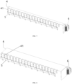
FIG. 1 is a three-dimensional diagram of a battery module according to an embodiment of the present disclosure; -
FIG. 2 is an exploded view of a battery module according to an embodiment of the present disclosure; -
FIG. 3 is a first schematic diagram of one end of a battery module according to an embodiment of the present disclosure; -
FIG. 4 is a first schematic diagram of the other end of a battery module according to an embodiment of the present disclosure; -
FIG. 5 is a second schematic diagram of one end of a battery module according to an embodiment of the present disclosure; -
FIG. 6 is a second schematic diagram of the other end of a battery module according to an embodiment of the present disclosure; -
FIG. 7 is a first schematic diagram of matching of a sampling portion and a protection portion of a battery module according to an embodiment of the present disclosure; -
FIG. 8 is a second schematic diagram of matching of a sampling portion and a protection portion of a battery module according to an embodiment of the present disclosure; -
FIG. 9 is a third schematic diagram of matching of a sampling portion and a protection portion of a battery module according to an embodiment of the present disclosure; -
FIG. 10 is a fourth schematic diagram of matching of a sampling portion and a protection portion of a battery module according to an embodiment of the present disclosure; -
FIG. 11 is a schematic diagram of a battery pack according to an embodiment of the present disclosure; and -
FIG. 12 is a schematic diagram of a vehicle according to an embodiment of the present disclosure. - In the drawings:
1, frame; 11, lower plate; 12, upper plate; 13, side plate; 14, accommodation cavity; 2, battery core; 21, housing; 22, explosion-proof valve; 23, terminal; 3, connection sheet; 4, sampling portion; 41, sampling terminal; 411, first sampling terminal; 411a, first connection segment; 411b, second connection segment; 412, second sampling terminal; 42, output terminal; 5, protection portion; 6, sampler; 7, welding portion; 100, battery module; 200, battery pack; 300, vehicle; P, positive electrode side of battery core assembly; and N, negative electrode side of battery core assembly. - Various exemplary embodiments of the present disclosure are now described in detail with reference to accompanying drawings. It is to be noted that: unless otherwise specified, relative arrangement, numerical expressions, and numerical values of components and steps described in these embodiments do not limit scope of the present disclosure.
- The following descriptions of at least one exemplary embodiment are merely illustrative, and in no way constitute any limitation on the present disclosure and application or use of the present disclosure.
- Technologies, methods, and devices known to those of ordinary skill in related arts may not be discussed in detail, but where appropriate, the technologies, the methods, and the devices are to be considered as a part of the specification.
- In all examples shown and discussed herein, any specific value are merely to be construed as examples but not limitations. Therefore, other examples of exemplary embodiments may have different values.
- It is to be noted that: similar reference signs and letters represent similar items in the following drawings. Therefore, once an item is defined in a drawing, it is not required to be further discussed in subsequent drawings.
- Referring to
FIG. 1 to FIG. 10 , embodiments of the present disclosure provide abattery module 100. Thebattery module 100 may be applied to a power battery of an electric vehicle. Thebattery module 100 includes:
a battery core assembly and a sampling assembly. The sampling assembly is configured to sample battery core information of the battery core assembly, for example, sampling a temperature, a pressure, an electrolyte storage capacity, and the like of the battery core assembly, so as to ensure stable performance of thebattery module 100. - Referring to
FIG. 2 andFIG. 3 , the battery core assembly includesmultiple battery cores 2. Two opposite ends of thebattery core 2 are provided with terminals. Positive and negative electrodes may sequentially alternate at one end of themultiple battery cores 2, and positive and negative electrodes may sequentially alternate at the other end of themultiple battery cores 2, so as to facilitate series connection of themultiple battery cores 2, as shown inFIG. 1 . - Referring to
FIG. 1 to FIG. 3 , themultiple battery cores 2 are sequentially connected in series throughconnection sheets 3. Two opposite ends of thebattery core 2 are provided with the terminals, that is, themultiple connection sheets 3 are arranged at both ends of the battery core assembly. Thebattery core 2 includes ahousing 21. An explosion-proof valve 22 may be arranged on thehousing 21. Continuing to refer toFIG. 4 , theconnection sheet 3 connected to a positive electrode of eachbattery core 2 is electrically connected to ahousing 21 of the correspondingbattery core 2 on a positive electrode side P of the battery core assembly. Specifically, a portion on eachconnection sheet 3 electrically connected to a positive electrode of thebattery core 2 is connected to thehousing 21 of the correspondingbattery core 2. Theconnection sheet 3 applies a voltage to thehousing 21 of thebattery core 2, that is, thehousing 21 and the explosion-proof valve 22 have the voltage, an electric potential of thehousing 21 and the explosion-proof valve 22 is improved, and thehousing 21 and the explosion-proof valve 22 are protected. - Referring to
FIG. 2 andFIG. 3 , thehousing 21 on a negative electrode side N of the battery core assembly is electrically connected to theconnection sheet 3 through the sampling assembly, so that thesampling portion 4 may protect the electric potential of thehousing 21 on the basis of collecting the battery core information such as a temperature, a pressure, and an electrolyte storage capacity of eachbattery core 2. Specifically, after themultiple battery cores 2 are sequentially connected in series through theconnection sheets 3, a total positive terminal and a total negative terminal directly connected to the outside may be formed. A side where the total positive terminal is located is the positive electrode side P of the battery core assembly, and a side where the total negative terminal is located is the negative electrode side N of the battery core assembly. - Specifically, the explosion-
proof valve 22 may be made of a thin aluminum material. After a voltage is applied to thehousing 21 through theconnection sheet 3, that is, the explosion-proof valve 22 on thehousing 21 has the voltage, the damage caused by infiltrating thehousing 21 and the explosion-proof valve 22 by an electrolyte in thebattery core 2 can be reduced, the integrity and stability of thehousing 21 and the explosion-proof valve 22 are ensured, and the use safety of thebattery module 100 is improved. Moreover, the sampling assembly may sample on a single side, that is, the sampling assembly is only arranged on one side of the battery core assembly, which simplifies a structure of the sampling assembly, and reduces the design cost of the sampling assembly. - The
battery module 100 provided by the embodiments of the present disclosure includes a battery core assembly and a sampling assembly. The battery core assembly includesmultiple battery cores 2. Two opposite ends of thebattery core 2 are provided with the terminals. Themultiple battery cores 2 are sequentially connected in series throughconnection sheets 3. Thebattery core 2 includes ahousing 21. Theconnection sheet 3 connected to a positive electrode of each of thebattery cores 2 is electrically connected to thehousing 21 of the correspondingbattery core 2. After a voltage is applied to thehousing 21 through the sampling assembly, that is, thehousing 21 has the voltage, the damage caused by infiltrating thehousing 21 by an electrolyte in thebattery core 2 can be reduced, the integrity and stability of thehousing 21 are ensured, and the use safety of thebattery module 100 is improved. In addition, thehousing 21 of thebattery core 2 is charged, and then the sampling assembly may sample on a single side, which simplifies a structure of the sampling assembly, and reduces the design cost of the sampling assembly. - Optionally, referring to
FIG. 1 to FIG. 3 , the sampling assembly includes asampling portion 4. Thesampling portion 4 includes asampling terminal 41 and anoutput terminal 42. Thesampling terminal 41 is electrically connected to thehousing 21 and/or theconnection sheet 3. - Specifically, the
sampling portion 4 is electrically connected to thehousing 21 through thesampling terminal 41, and theoutput terminal 42 is connected to an external sampling device, so as to collect and transmit the battery core information such as a temperature, a pressure, and an electrolyte storage capacity of thebattery core 2 to an external sampling device, and then process and monitor the information to ensure operating stability of thebattery module 100. When thesampling terminal 41 is electrically connected to theconnection sheet 3, thehousing 21 may be charged through theconnection sheet 3, which ensures integrity and stability of thehousing 21. - Optionally,
welding portions 7 are arranged on thehousing 21, and thesampling portion 4 is electrically connected to thewelding portions 7 through thesampling terminal 41. - Specifically, one end of the
sampling terminal 41 may overlap on a sampling main body of thesampling portion 4, and the other end or a middle position of thesampling terminal 41 may be welded on thewelding portion 7 of thehousing 21. Thewelding portion 7 may be specifically a welding spot set on thehousing 21, so as to weld thesampling terminal 41 and thehousing 21. Through thewelding portion 7, thehousing 21 may be electrically connected to thesampling portion 4 through thesampling terminal 41. By means of characteristics of high welding speed, low thermal deformation, high density, and the like of thesampling terminal 41, thesampling portion 4 may be ensured to effectively collect the battery core information of each of thebattery cores 2, such as a temperature, a pressure, and an electrolyte storage capacity. - Optionally, referring to
FIG. 3 andFIG. 6 , thesampling terminal 41 includes afirst sampling terminal 411 and asecond sampling terminal 412. Thefirst sampling terminal 411 is electrically connected to thewelding portion 7 and theconnection sheet 3. Thesecond sampling terminal 412 is electrically connected to thewelding portion 7. - When the
housing 21 on a negative electrode side N of the battery core assembly is electrically connected to theconnection sheet 3 through the sampling assembly, thewelding portion 7 may be electrically connected to theconnection sheet 3 through thefirst sampling terminal 411. That is, thefirst sampling terminal 411 can achieve collection of the information in thebattery core 2 by thesampling portion 4 through thewelding portion 7, and can apply the voltage to thehousing 21 through theconnection sheet 3. Part sampling terminals of thesampling terminals 41 only need to collect the information in thebattery core 2, alternatively thesecond sampling terminal 412 may be connected to thewelding portion 7 only. Thesecond sampling terminal 412 achieves collection of the information in thebattery core 2 by thesampling portion 4 through thewelding portion 7, which simplifies a structure of thesampling terminal 41. Theconnection sheet 3 may be electrically connected to thehousing 21 through an assembly provided with a protection circuit. - Optionally, the
first sampling terminal 411 includes afirst connection segment 411a and asecond connection segment 411b, thesampling portion 4 is electrically connected to thewelding portion 7 through thefirst connection segment 41 1a, and theconnection sheet 3 is electrically connected to thewelding portion 7 through thesecond connection segment 411b. - Specifically, when the
sampling portion 4 samples thebattery core 2 through thefirst connection segment 411a, theconnection sheet 3 may apply a voltage to thehousing 21 through thesecond connection segment 411b, and a safety circuit may be arranged on thesecond connection segment 411b. Thefirst sampling terminal 411 is formed after thefirst connection segment 411a and thesecond connection segment 411b are integrally formed. One end of thefirst sampling terminal 411 is connected to thewelding portion 7, and the other end of thefirst sampling terminal 411 is connected to theconnection sheet 3. The middle position of thefirst sampling terminal 411 may be welded to thehousing 21 of thebattery core 2. That is, voltage application to thehousing 21 of thebattery core 2 and the sampling of thesampling portion 4 may be achieved at the same time by only welding a middle part of thefirst sampling terminal 411 once, which simplifies a structure of thefirst sampling terminal 411 and reduces time cost of production. - Optionally, referring to
FIG. 2 to FIG. 7 , the sampling assembly includes aprotection portion 5. One end of theprotection portion 5 is electrically connected to thesampling terminal 41 and thewelding portion 7, and the other end of theprotection portion 5 is connected to theconnection sheet 3. - Specifically, after a voltage is applied to the
housing 21 through theconnection sheet 3, since theconnection sheet 3 is directly connected to a terminal of thebattery core 2, to avoid the damage to thehousing 21 by theconnection sheet 3 when the voltage is too high, theprotection portion 5 may be arranged between theconnection sheet 3 and thewelding portion 7 of thehousing 21. Theprotection portion 5 may be specifically a fuse protector (a fuse protection circuit), a fuse wire, or the like, so as to ensure stability of the voltage on thehousing 21. - Optionally, the
sampling portion 4 and theprotection portion 5 are at least one of an FPC or a PCB. In addition, referring toFIG. 2 to FIG. 5 , thesampling portion 4 and theprotection portion 5 may be integrally formed into an assembly. - Specifically, the assembly may have an assembly substrate, for example, the assembly substrate may be a PCB substrate or a FPC substrate. Both the
sampling portion 4 and theprotection portion 5 may be formed on the assembly substrate, so as to improve the integrity and compactness of thesampling portion 4 and theprotection portion 5. - Optionally, the
sampling portion 4 and theprotection portion 5 are PCBs or double-sided FPCs. Referring toFIG. 2 andFIG. 3 , in a case that thesampling portion 4 and theprotection portion 5 are the PCBs, thesampling portion 4 and theprotection portion 5 may be formed on the PCB substrate together, so that the assembly forms the PCB. The PCB may be an integrated battery information collector (BIC). Through an arrangement of a PCB assembly, performance of thesampling portion 4 and theprotection portion 5 can be ensured, and impact of electromagnetic interference on thesampling portion 4 and theprotection portion 5 can be reduced by using good Electromagnetic Compatibility (EMC) of the PCB. In a case that thesampling portion 4 and theprotection portion 5 are FPCs, thesampling portion 4 and theprotection portion 5 may be two independent two FPCs respectively, referring toFIG. 4 to FIG. 9 . Alternatively, a circuit of thesampling portion 4 may be etched on one side of the FPC substrate, as shown inFIG. 7 , and a circuit of theprotection portion 5 may be etched on the other side of the FPC substrate, as shown inFIG. 8 , so as to form the double-sided FPC, as shown inFIG. 9 . - Optionally, referring to
FIG. 1 to FIG. 3 , thesampling portion 4 is arranged at a top side of the battery core assembly. - Specifically, the two opposite ends of the
battery core 2 are provided with theterminals 23, thebattery core 2 is transversely placed in aframe 1, and the top side of the battery core assembly has a flat top surface, so a width dimension of the sampling portion 4 (that is, a dimension in an extending direction of the battery core 2) is not affected by structures such as the terminals on a side surface of thebattery core 2, and a height of the side surface of thebattery core 2 will not affect the dimension of thesampling portion 4 when thesampling portion 4 is arranged at the top side of the battery core assembly. The width dimension of thesampling portion 4 may be flexibly adjusted. For example, a width of thesampling portion 4 may be made wider, such as a change of thesampling portion 4 inFIG. 8 relative to thesampling portion 4 inFIG. 7 , and a change of thesampling portion 4 inFIG. 10 relative to thesampling portion 4 inFIG. 9 , so as to meet a space required by wiring in thesampling portion 4. - Moreover, the
sampling portion 4 may not overlap with a high-voltage loop at an end portion of thebattery core 2, which reduces a risk of the EMC of thesampling portion 4. - Optionally, referring to
FIG. 1 to FIG. 3 , andFIG. 7 and FIG. 8 , theprotection portion 5 is arranged at an end portion of the battery core assembly provided with the terminal 23. - Specifically, the two opposite ends of the
battery core 2 are provided with theterminals 23, that is, themultiple connection sheets 3 are arranged at both ends of the battery core assembly. To facilitate arranging theprotection portion 5 between theconnection sheet 3 and thehousing 21, theprotection portion 5 may be arranged at the end portion of the battery core assembly. Thesampling portion 4 is arranged at the top side of the battery core assembly, and thesampling portion 4 and theprotection portion 5 may form structures perpendicular to each other, so that theprotection portion 5 and theconnection sheet 3 are located at the same end of thebattery core 2. In this way, theconnection sheet 3 may be conveniently connected to the housing at a corresponding end of thebattery core 2 through theprotection portion 5 to simplify a structure of theprotection portion 5. - Optionally, referring
FIG. 9 and FIG. 10 , theprotection portion 5 is arranged in parallel to thesampling portion 4. - Specifically, since the
connection sheet 3 is directly connected to theterminal 23 of thebattery core 2, to avoid the interference of theconnection sheet 3 on theprotection portion 5 when the voltage is too high, theprotection portion 5 may be arranged in parallel to thesampling portion 4. Thesampling portion 4 is arranged on the top side of the battery core assembly, that is, theprotection portion 5 may alternatively be arranged at the top side of the battery core assembly or in a space higher than the battery core assembly, so as to ensure stable performance of theprotection portion 5. - Optionally, referring to
FIG. 1 , thesampling portion 4 is a first flexible connection member, and the first flexible connection member is inserted into and matches thesampler 6 through a plug connector. - Specifically, the first flexible connection member may be an FPC, a flexible flat cable (FFC), or a flexible conductive cable (FDC), and a width of the first flexible connection member is adjustable. In a case that the first flexible connection member is electrically connected to the
housing 21 of each of thebattery cores 2, thesampler 6 may process the battery core information of each of thebattery cores 2 collected by the first flexible connection member after the plug connector is inserted into and matches thesampler 6. Since the first flexible connection member has a flexible structure, a position and an extending direction of the first flexible connection member may be flexibly set, which improves the structural flexibility of thesampling portion 4. - Optionally, referring to
FIG. 1 to FIG. 2 , theprotection portion 5 is a second flexible connection member, and a protection circuit connected to theconnection sheet 3 and thehousing 21 is arranged in the second flexible connection member. - Specifically, the second flexible connection member may be an FPC, an FFC, or an FDC. One end of the second flexible connection member may be electrically connected to the
connection sheet 3, and the other end of the second flexible connection member may be connected to thehousing 21, so as to apply a voltage to thehousing 21 of thebattery core 2 through theconnection sheet 3. To avoid the damage to thehousing 21 caused by theconnection sheet 3 when the voltage is too high, a protection circuit connected to theconnection sheet 3 and thehousing 21 may be arranged in the second flexible connection member. The protection circuit may be a fuse protector (a fuse protection circuit), a fuse wire, or the like, so as to ensure the structural integrity of thehousing 21. - Optionally, the
battery module 100 further includes aframe 1; and themultiple battery cores 2 are arranged in theframe 1 side by side. - Specifically, referring to
FIG. 2 , theframe 1 may include alower plate 11, anupper plate 12, andside plates 13. Theside plates 13 are connected between thelower plate 11 and theupper plate 12. Thelower plate 11, theupper plate 12, and theside plates 13 form anaccommodation cavity 14 in a manner of bonding, welding, or threaded connection. The battery core assembly is arranged in theaccommodation cavity 14 in theframe 1. Theframe 1 may provide support and protection for the battery core assembly. - Refer to
FIG. 11 , which is a schematic diagram of a battery pack according to an embodiment of the present disclosure. The present disclosure further provides abattery pack 200. Thebattery pack 200 includes at least one of thebattery modules 100. - Specifically, the
battery pack 200 may serve as a power battery of a vehicle. Thebattery module 100 includes a battery core assembly and a sampling assembly. The battery core assembly includesmultiple battery cores 2. Two opposite ends of thebattery core 2 are provided with terminals. Themultiple battery cores 2 are sequentially connected in series throughconnection sheets 3. Thebattery core 2 includes ahousing 21. Theconnection sheet 3 connected to a positive electrode of each of thebattery cores 2 is electrically connected to thehousing 21 of the correspondingbattery core 2. After a voltage is applied to thehousing 21 through the sampling assembly, that is, thehousing 21 has the voltage, the damage caused by infiltrating thehousing 21 by an electrolyte in thebattery core 2 can be reduced, the integrity and stability of thehousing 21 are ensured, and the use safety of thebattery module 200 is improved. - Referring to
FIG. 12 , which is a schematic diagram of a vehicle according to an embodiment of the present disclosure. The embodiments of the present disclosure further provides avehicle 300. The vehicle includes abattery pack 200. At least one of thebattery modules 100 is arranged in thebattery pack 200. - Specifically, the
battery module 100 of thevehicle 300 includes a battery core assembly and a sampling assembly. The battery core assembly includesmultiple battery cores 2. Two opposite ends of thebattery core 2 are provided with terminals. Themultiple battery cores 2 are sequentially connected in series throughconnection sheets 3. Thebattery core 2 includes ahousing 21. Theconnection sheet 3 connected to a positive electrode of each of thebattery cores 2 is electrically connected to thehousing 21 of the correspondingbattery core 2. After a voltage is applied to thehousing 21 through the sampling assembly, that is, thehousing 21 has the voltage, the damage caused by infiltrating thehousing 21 by an electrolyte in thebattery core 2 can be reduced, the integrity and stability of thehousing 21 are ensured, and the use safety of thevehicle 300 is improved. - Although some specific embodiments of the present disclosure have been described in detail by way of examples, those skilled in the art are to be understood that the foregoing examples are only for description and are not intended to limit the scope of the present disclosure. Those skilled in the art are to be understood that modifications may be made to the foregoing embodiments without departing from the scope and spirit of the present disclosure. The scope of the present disclosure is limited by appended claims.
Claims (18)
- A battery module (100), comprising:a battery core assembly, the battery core assembly comprising a plurality of battery cores (2), two opposite ends of each battery core (2) of the plurality of the battery cores (2) being provided with terminals (23), the plurality of the battery cores (2) being sequentially connected in series through connection sheets (3), each battery core (2) comprising a housing (21), and the connection sheet (3)connected to a positive electrode of each battery core (2) being electrically connected to the housing (21) of the corresponding battery core (2) on a positive electrode side of the battery core assembly; anda sampling assembly, the housing (21) on a negative electrode side (N) of the battery core assembly being electrically connected to the connection sheet (3) through the sampling assembly.
- The battery module (100) according to claim 1, wherein the sampling assembly comprises a sampling portion (4), the sampling portion (4) comprises a sampling terminal (41) and an output terminal (42), and the sampling terminal (41) is electrically connected to the housing (21) and/or the connection sheet (3).
- The battery module (100) according to claim 2, wherein welding portions (7) are arranged on the housing (21), and the sampling portion (4) is electrically connected to the welding portions (7) through the sampling terminal (41).
- The battery module (100) according to claim 3, wherein the sampling terminal (41) comprises a first sampling terminal (411) and a second sampling terminal (412), the first sampling terminal (411) is electrically connected to one of the welding portions (7) and to the connection sheets (3), and the second sampling terminal (412) is electrically connected to another welding portion (7).
- The battery module (100) according to claim 4, wherein the first sampling terminal (411) comprises a first connection segment (411a) and a second connection segment (411b), the sampling portion (4) is electrically connected to the welding portion (7) through the first connection segment (411a), and the connection sheet (3) is electrically connected to the welding portion (7) through the second connection segment (41 1b).
- The battery module (100) according to claim 5, wherein the first sampling terminal (411) is configured to collect information in the battery core (2) by the sampling portion (4) through the welding portion (7), and to apply a voltage to the housing (21) through the connection sheet (3); and
the second sampling terminal (412) is configured to collect the information in the battery core (2) by the sampling portion (4) through the welding portion (7). - The battery module (100) according to any one of claims 3 to 6, wherein the sampling assembly comprises a protection portion (5), one end of the protection portion (5) is electrically connected to the sampling terminal (41) and the welding portion (7), and the other end of the protection portion (5) is connected to the connection sheet (3).
- The battery module (100) according to claim 7, wherein the sampling portion (4) and the protection portion (5) are at least one of a flexible printed circuit (FPC) or a printed circuit board (PCB).
- The battery module (100) according to claim 7 or 8, wherein the sampling portion (4) and the protection portion (5) are integrally formed.
- The battery module (100) according to any one of claims 7 to 9, wherein the sampling portion (4) is arranged at a top side of the battery core assembly, and the protection portion (5) is arranged parallel to the sampling portion (4).
- The battery module (100) according to any one of claims 7 to 9, wherein the sampling portion (4) is perpendicular to the protection portion (5).
- The battery module (100) according to any one of claims 7 to 11, wherein the protection portion (5) is arranged on one side of the battery core assembly provided with the terminal (23).
- The battery module (100) according to any one of claims 1 to 12, wherein the sampling portion (4) is a first flexible connection member, and the first flexible connection member is inserted into and matches a sampler (6).
- The battery module (100) according to any one of claims 7 to 13, wherein the protection portion (5) is a second flexible connection member, and a protection circuit connected to the connection sheet (3) and the housing (21) is arranged in the second flexible connection member.
- The battery module (100) according to claim 14, wherein the protection circuit comprises a fuse protector or a fuse wire.
- The battery module (100) according to any one of claims 1 to 15, further comprising a frame (1); and
the plurality of the battery cores (2) being arranged in the frame (1) side by side. - A battery pack (200), comprising the battery module (100) according to any one of claims 1 to 16.
- A vehicle (300), comprising the battery module (100) according to any one of claims 1 to 16 and the battery pack (200) according to claim 17.
Applications Claiming Priority (2)
| Application Number | Priority Date | Filing Date | Title |
|---|---|---|---|
| CN202220482834.0U CN217134519U (en) | 2022-03-07 | 2022-03-07 | Battery modules, battery packs and vehicles |
| PCT/CN2023/080041 WO2023169406A1 (en) | 2022-03-07 | 2023-03-07 | Battery module, battery pack, and vehicle |
Publications (2)
| Publication Number | Publication Date |
|---|---|
| EP4439816A1 true EP4439816A1 (en) | 2024-10-02 |
| EP4439816A4 EP4439816A4 (en) | 2025-04-30 |
Family
ID=82643149
Family Applications (1)
| Application Number | Title | Priority Date | Filing Date |
|---|---|---|---|
| EP23765984.2A Pending EP4439816A4 (en) | 2022-03-07 | 2023-03-07 | BATTERY MODULE, BATTERY PACK AND VEHICLE |
Country Status (6)
| Country | Link |
|---|---|
| US (1) | US20240356180A1 (en) |
| EP (1) | EP4439816A4 (en) |
| JP (1) | JP2025506597A (en) |
| KR (1) | KR20240112338A (en) |
| CN (1) | CN217134519U (en) |
| WO (1) | WO2023169406A1 (en) |
Families Citing this family (8)
| Publication number | Priority date | Publication date | Assignee | Title |
|---|---|---|---|---|
| CN217134519U (en) * | 2022-03-07 | 2022-08-05 | 比亚迪股份有限公司 | Battery modules, battery packs and vehicles |
| CN117673657A (en) * | 2022-08-25 | 2024-03-08 | 上汽通用汽车有限公司 | Cell components, battery packs and vehicles |
| CN115663406B (en) * | 2022-11-14 | 2026-03-03 | 合肥国轩高科动力能源有限公司 | Battery cell adapter, battery cell stack and no-module battery pack |
| CN115911741A (en) * | 2023-01-09 | 2023-04-04 | 广汽埃安新能源汽车股份有限公司 | Battery pack structure and electrical equipment |
| CN116345036A (en) * | 2023-03-27 | 2023-06-27 | 广东博力威科技股份有限公司 | Soft-pack battery module and assembly method thereof |
| KR20250060749A (en) * | 2023-10-26 | 2025-05-07 | 삼성에스디아이 주식회사 | Battery module |
| DE102024200134B3 (en) * | 2024-01-07 | 2024-12-24 | Volkswagen Aktiengesellschaft | storage device and motor vehicle |
| CN119208851A (en) * | 2024-11-27 | 2024-12-27 | 宁德时代新能源科技股份有限公司 | Battery devices, energy storage devices and power consumption devices |
Family Cites Families (8)
| Publication number | Priority date | Publication date | Assignee | Title |
|---|---|---|---|---|
| JP6204876B2 (en) * | 2014-06-04 | 2017-09-27 | 株式会社オートネットワーク技術研究所 | Temperature sensor mounting structure |
| KR101913786B1 (en) * | 2015-07-21 | 2018-10-31 | 주식회사 엘지화학 | Battery Module for Direct Connection Structure Between Terminal Plate and Battery Management System |
| JP7403240B2 (en) * | 2019-06-07 | 2023-12-22 | 日本メクトロン株式会社 | Wiring materials and battery modules |
| CN112582759B (en) * | 2019-09-30 | 2022-05-13 | 比亚迪股份有限公司 | Battery module and electric automobile |
| CN113054330A (en) * | 2019-12-26 | 2021-06-29 | 比亚迪股份有限公司 | Battery module and power battery pack and electric automobile with same |
| CN214848959U (en) * | 2020-12-01 | 2021-11-23 | 惠州比亚迪实业有限公司 | Battery module, battery pack with same and vehicle |
| CN214542432U (en) * | 2021-05-14 | 2021-10-29 | 中航锂电科技有限公司 | Battery pack, battery pack and vehicle |
| CN217134519U (en) * | 2022-03-07 | 2022-08-05 | 比亚迪股份有限公司 | Battery modules, battery packs and vehicles |
-
2022
- 2022-03-07 CN CN202220482834.0U patent/CN217134519U/en active Active
-
2023
- 2023-03-07 JP JP2024535642A patent/JP2025506597A/en active Pending
- 2023-03-07 EP EP23765984.2A patent/EP4439816A4/en active Pending
- 2023-03-07 WO PCT/CN2023/080041 patent/WO2023169406A1/en not_active Ceased
- 2023-03-07 KR KR1020247021432A patent/KR20240112338A/en active Pending
-
2024
- 2024-06-30 US US18/759,924 patent/US20240356180A1/en active Pending
Also Published As
| Publication number | Publication date |
|---|---|
| EP4439816A4 (en) | 2025-04-30 |
| WO2023169406A1 (en) | 2023-09-14 |
| US20240356180A1 (en) | 2024-10-24 |
| JP2025506597A (en) | 2025-03-13 |
| KR20240112338A (en) | 2024-07-18 |
| CN217134519U (en) | 2022-08-05 |
Similar Documents
| Publication | Publication Date | Title |
|---|---|---|
| US20240356180A1 (en) | Battery module, battery pack, and vehicle | |
| EP1807900B1 (en) | Member for measurement of cell voltage and temperature in battery pack | |
| EP1812982B1 (en) | Secondary battery pack having configuration of alternative orientation | |
| EP3933952B1 (en) | Battery module, battery pack and device | |
| EP3930084B1 (en) | Connection assembly, battery module, battery pack, device, and manufacturing method | |
| CN219106259U (en) | Battery module | |
| CN118299767A (en) | Battery packs and power-consuming devices | |
| CN110474078B (en) | Soft package standard module and assembling method | |
| EP4525153A1 (en) | Battery assembly, electric device and battery assembly preparation method | |
| US20240266694A1 (en) | Electrode terminal, pole assembly, battery, and electric device | |
| WO2022126883A1 (en) | Battery and apparatus | |
| CN218569144U (en) | Battery pack and electric device | |
| CN219843020U (en) | Battery cell sampling plate, battery and electricity utilization device | |
| CN217823177U (en) | Battery and electronic device | |
| CN222927740U (en) | Battery, battery cell and electricity utilization device | |
| CN211555993U (en) | A bar battery pack | |
| CN217507575U (en) | Battery connector group, battery and electric device | |
| CN110492049A (en) | Battery and battery pack | |
| CN116706409A (en) | Battery, its manufacturing method and manufacturing system, and electrical device | |
| KR20130134431A (en) | Charging and discharging device of battery cell | |
| CN223079310U (en) | A battery pack | |
| CN216903439U (en) | Connecting device, battery and electric equipment | |
| CN223986622U (en) | Batteries, battery packs and electrical equipment | |
| CN224006074U (en) | Bus bar assembly and battery module including the same | |
| CN218005160U (en) | Battery pack, energy storage device thereof and energy storage device control system |
Legal Events
| Date | Code | Title | Description |
|---|---|---|---|
| STAA | Information on the status of an ep patent application or granted ep patent |
Free format text: STATUS: THE INTERNATIONAL PUBLICATION HAS BEEN MADE |
|
| PUAI | Public reference made under article 153(3) epc to a published international application that has entered the european phase |
Free format text: ORIGINAL CODE: 0009012 |
|
| STAA | Information on the status of an ep patent application or granted ep patent |
Free format text: STATUS: REQUEST FOR EXAMINATION WAS MADE |
|
| 17P | Request for examination filed |
Effective date: 20240628 |
|
| AK | Designated contracting states |
Kind code of ref document: A1 Designated state(s): AL AT BE BG CH CY CZ DE DK EE ES FI FR GB GR HR HU IE IS IT LI LT LU LV MC ME MK MT NL NO PL PT RO RS SE SI SK SM TR |
|
| REG | Reference to a national code |
Ref country code: DE Ref legal event code: R079 Free format text: PREVIOUS MAIN CLASS: H01M0050202000 Ipc: H01M0010420000 |
|
| A4 | Supplementary search report drawn up and despatched |
Effective date: 20250327 |
|
| RIC1 | Information provided on ipc code assigned before grant |
Ipc: H01M 50/548 20210101ALI20250321BHEP Ipc: H01M 50/519 20210101ALI20250321BHEP Ipc: H01M 50/516 20210101ALI20250321BHEP Ipc: H01M 50/502 20210101ALI20250321BHEP Ipc: H01M 50/249 20210101ALI20250321BHEP Ipc: H01M 50/209 20210101ALI20250321BHEP Ipc: H01M 50/204 20210101ALI20250321BHEP Ipc: H01M 10/48 20060101ALI20250321BHEP Ipc: H01M 10/42 20060101AFI20250321BHEP |
|
| DAV | Request for validation of the european patent (deleted) | ||
| DAX | Request for extension of the european patent (deleted) |