EP4439805A1 - Battery pack having structure for delaying heat propagation - Google Patents
Battery pack having structure for delaying heat propagation Download PDFInfo
- Publication number
- EP4439805A1 EP4439805A1 EP23863424.0A EP23863424A EP4439805A1 EP 4439805 A1 EP4439805 A1 EP 4439805A1 EP 23863424 A EP23863424 A EP 23863424A EP 4439805 A1 EP4439805 A1 EP 4439805A1
- Authority
- EP
- European Patent Office
- Prior art keywords
- cooling plate
- slot
- center frame
- pack case
- side beam
- Prior art date
- Legal status (The legal status is an assumption and is not a legal conclusion. Google has not performed a legal analysis and makes no representation as to the accuracy of the status listed.)
- Pending
Links
Images



Classifications
-
- H—ELECTRICITY
- H01—ELECTRIC ELEMENTS
- H01M—PROCESSES OR MEANS, e.g. BATTERIES, FOR THE DIRECT CONVERSION OF CHEMICAL ENERGY INTO ELECTRICAL ENERGY
- H01M10/00—Secondary cells; Manufacture thereof
- H01M10/60—Heating or cooling; Temperature control
- H01M10/61—Types of temperature control
- H01M10/613—Cooling or keeping cold
-
- H—ELECTRICITY
- H01—ELECTRIC ELEMENTS
- H01M—PROCESSES OR MEANS, e.g. BATTERIES, FOR THE DIRECT CONVERSION OF CHEMICAL ENERGY INTO ELECTRICAL ENERGY
- H01M10/00—Secondary cells; Manufacture thereof
- H01M10/60—Heating or cooling; Temperature control
- H01M10/65—Means for temperature control structurally associated with the cells
- H01M10/655—Solid structures for heat exchange or heat conduction
- H01M10/6554—Rods or plates
-
- H—ELECTRICITY
- H01—ELECTRIC ELEMENTS
- H01M—PROCESSES OR MEANS, e.g. BATTERIES, FOR THE DIRECT CONVERSION OF CHEMICAL ENERGY INTO ELECTRICAL ENERGY
- H01M10/00—Secondary cells; Manufacture thereof
- H01M10/60—Heating or cooling; Temperature control
- H01M10/65—Means for temperature control structurally associated with the cells
- H01M10/655—Solid structures for heat exchange or heat conduction
- H01M10/6554—Rods or plates
- H01M10/6555—Rods or plates arranged between the cells
-
- H—ELECTRICITY
- H01—ELECTRIC ELEMENTS
- H01M—PROCESSES OR MEANS, e.g. BATTERIES, FOR THE DIRECT CONVERSION OF CHEMICAL ENERGY INTO ELECTRICAL ENERGY
- H01M10/00—Secondary cells; Manufacture thereof
- H01M10/60—Heating or cooling; Temperature control
- H01M10/65—Means for temperature control structurally associated with the cells
- H01M10/656—Means for temperature control structurally associated with the cells characterised by the type of heat-exchange fluid
-
- H—ELECTRICITY
- H01—ELECTRIC ELEMENTS
- H01M—PROCESSES OR MEANS, e.g. BATTERIES, FOR THE DIRECT CONVERSION OF CHEMICAL ENERGY INTO ELECTRICAL ENERGY
- H01M10/00—Secondary cells; Manufacture thereof
- H01M10/60—Heating or cooling; Temperature control
- H01M10/65—Means for temperature control structurally associated with the cells
- H01M10/658—Means for temperature control structurally associated with the cells by thermal insulation or shielding
-
- H—ELECTRICITY
- H01—ELECTRIC ELEMENTS
- H01M—PROCESSES OR MEANS, e.g. BATTERIES, FOR THE DIRECT CONVERSION OF CHEMICAL ENERGY INTO ELECTRICAL ENERGY
- H01M50/00—Constructional details or processes of manufacture of the non-active parts of electrochemical cells other than fuel cells, e.g. hybrid cells
- H01M50/20—Mountings; Secondary casings or frames; Racks, modules or packs; Suspension devices; Shock absorbers; Transport or carrying devices; Holders
- H01M50/204—Racks, modules or packs for multiple batteries or multiple cells
-
- H—ELECTRICITY
- H01—ELECTRIC ELEMENTS
- H01M—PROCESSES OR MEANS, e.g. BATTERIES, FOR THE DIRECT CONVERSION OF CHEMICAL ENERGY INTO ELECTRICAL ENERGY
- H01M50/00—Constructional details or processes of manufacture of the non-active parts of electrochemical cells other than fuel cells, e.g. hybrid cells
- H01M50/20—Mountings; Secondary casings or frames; Racks, modules or packs; Suspension devices; Shock absorbers; Transport or carrying devices; Holders
- H01M50/258—Modular batteries; Casings provided with means for assembling
-
- H—ELECTRICITY
- H01—ELECTRIC ELEMENTS
- H01M—PROCESSES OR MEANS, e.g. BATTERIES, FOR THE DIRECT CONVERSION OF CHEMICAL ENERGY INTO ELECTRICAL ENERGY
- H01M50/00—Constructional details or processes of manufacture of the non-active parts of electrochemical cells other than fuel cells, e.g. hybrid cells
- H01M50/20—Mountings; Secondary casings or frames; Racks, modules or packs; Suspension devices; Shock absorbers; Transport or carrying devices; Holders
- H01M50/289—Mountings; Secondary casings or frames; Racks, modules or packs; Suspension devices; Shock absorbers; Transport or carrying devices; Holders characterised by spacing elements or positioning means within frames, racks or packs
- H01M50/291—Mountings; Secondary casings or frames; Racks, modules or packs; Suspension devices; Shock absorbers; Transport or carrying devices; Holders characterised by spacing elements or positioning means within frames, racks or packs characterised by their shape
-
- H—ELECTRICITY
- H01—ELECTRIC ELEMENTS
- H01M—PROCESSES OR MEANS, e.g. BATTERIES, FOR THE DIRECT CONVERSION OF CHEMICAL ENERGY INTO ELECTRICAL ENERGY
- H01M50/00—Constructional details or processes of manufacture of the non-active parts of electrochemical cells other than fuel cells, e.g. hybrid cells
- H01M50/20—Mountings; Secondary casings or frames; Racks, modules or packs; Suspension devices; Shock absorbers; Transport or carrying devices; Holders
- H01M50/289—Mountings; Secondary casings or frames; Racks, modules or packs; Suspension devices; Shock absorbers; Transport or carrying devices; Holders characterised by spacing elements or positioning means within frames, racks or packs
- H01M50/293—Mountings; Secondary casings or frames; Racks, modules or packs; Suspension devices; Shock absorbers; Transport or carrying devices; Holders characterised by spacing elements or positioning means within frames, racks or packs characterised by the material
-
- H—ELECTRICITY
- H01—ELECTRIC ELEMENTS
- H01M—PROCESSES OR MEANS, e.g. BATTERIES, FOR THE DIRECT CONVERSION OF CHEMICAL ENERGY INTO ELECTRICAL ENERGY
- H01M10/00—Secondary cells; Manufacture thereof
- H01M10/60—Heating or cooling; Temperature control
- H01M10/65—Means for temperature control structurally associated with the cells
- H01M10/653—Means for temperature control structurally associated with the cells characterised by electrically insulating or thermally conductive materials
-
- H—ELECTRICITY
- H01—ELECTRIC ELEMENTS
- H01M—PROCESSES OR MEANS, e.g. BATTERIES, FOR THE DIRECT CONVERSION OF CHEMICAL ENERGY INTO ELECTRICAL ENERGY
- H01M2220/00—Batteries for particular applications
- H01M2220/10—Batteries in stationary systems, e.g. emergency power source in plant
-
- H—ELECTRICITY
- H01—ELECTRIC ELEMENTS
- H01M—PROCESSES OR MEANS, e.g. BATTERIES, FOR THE DIRECT CONVERSION OF CHEMICAL ENERGY INTO ELECTRICAL ENERGY
- H01M2220/00—Batteries for particular applications
- H01M2220/20—Batteries in motive systems, e.g. vehicle, ship, plane
-
- H—ELECTRICITY
- H01—ELECTRIC ELEMENTS
- H01M—PROCESSES OR MEANS, e.g. BATTERIES, FOR THE DIRECT CONVERSION OF CHEMICAL ENERGY INTO ELECTRICAL ENERGY
- H01M50/00—Constructional details or processes of manufacture of the non-active parts of electrochemical cells other than fuel cells, e.g. hybrid cells
- H01M50/20—Mountings; Secondary casings or frames; Racks, modules or packs; Suspension devices; Shock absorbers; Transport or carrying devices; Holders
- H01M50/249—Mountings; Secondary casings or frames; Racks, modules or packs; Suspension devices; Shock absorbers; Transport or carrying devices; Holders specially adapted for aircraft or vehicles, e.g. cars or trains
-
- H—ELECTRICITY
- H01—ELECTRIC ELEMENTS
- H01M—PROCESSES OR MEANS, e.g. BATTERIES, FOR THE DIRECT CONVERSION OF CHEMICAL ENERGY INTO ELECTRICAL ENERGY
- H01M50/00—Constructional details or processes of manufacture of the non-active parts of electrochemical cells other than fuel cells, e.g. hybrid cells
- H01M50/20—Mountings; Secondary casings or frames; Racks, modules or packs; Suspension devices; Shock absorbers; Transport or carrying devices; Holders
- H01M50/251—Mountings; Secondary casings or frames; Racks, modules or packs; Suspension devices; Shock absorbers; Transport or carrying devices; Holders specially adapted for stationary devices, e.g. power plant buffering or backup power supplies
-
- Y—GENERAL TAGGING OF NEW TECHNOLOGICAL DEVELOPMENTS; GENERAL TAGGING OF CROSS-SECTIONAL TECHNOLOGIES SPANNING OVER SEVERAL SECTIONS OF THE IPC; TECHNICAL SUBJECTS COVERED BY FORMER USPC CROSS-REFERENCE ART COLLECTIONS [XRACs] AND DIGESTS
- Y02—TECHNOLOGIES OR APPLICATIONS FOR MITIGATION OR ADAPTATION AGAINST CLIMATE CHANGE
- Y02E—REDUCTION OF GREENHOUSE GAS [GHG] EMISSIONS, RELATED TO ENERGY GENERATION, TRANSMISSION OR DISTRIBUTION
- Y02E60/00—Enabling technologies; Technologies with a potential or indirect contribution to GHG emissions mitigation
- Y02E60/10—Energy storage using batteries
Definitions
- the present invention relates to a battery pack that can delay thermal propagation between battery modules stored in a battery pack.
- secondary batteries can be recharged, and they have been heavily researched and developed in recent years due to their potential for miniaturization and large capacity.
- the demand for secondary batteries as an energy source is increasing rapidly due to the technological development and increasing demand for mobile devices, electric vehicles, and energy storage systems, which are emerging in response to the need for environmental protection.
- Secondary batteries are categorized into coin-type cells, cylindrical cells, prismatic cells, and pouch-type cells based on the shape of the cell case.
- an electrode assembly mounted inside the battery case is a chargeable/dischargeable power generator consisting of a laminated structure of electrodes and separators.
- Patent Document 001 Korean Patent Publication No. 2022-0017741(published on February 21, 2022 )
- the present invention aims to provide a battery pack that can effectively suppress and prevent the phenomenon of thermal propagation in which heat transfer caused by thermal runaway generated by any secondary battery in a battery pack spreads to other secondary batteries or battery modules in the vicinity.
- the present invention relates to a pack case, where in one example, it includes a cooling plate equipped with a cooling flow path on the inside; a side plate coupled to form a side wall at the edge of the cooling plate; a center frame coupled to the cooling plate to longitudinally divide the storing space formed by the side plate; and a side beam coupled to the cooling plate to transversely divide a plurality of spaces divided by the center frame, wherein the cooling plate is provided with a slot formed by penetrating along the coupling position of the center frame or side beam.
- a plurality of the slots is spaced apart along the coupling position of the center frame or side beam.
- the slot may be formed of a size that does not extend beyond the center frame and side beam.
- a fastening point of the center frame or side beam is formed between the mutually spaced slots.
- the fastening point may be distributed at both ends and in the middle of the plurality of slots forming a row.
- cooling plate is characterized in that the cooling flow path and the slot may not overlap or intersect.
- an insulating material may be filled within the space formed by the slot, and the insulating material may be a watertight material.
- the pack case may further include a base plate coupled to the bottom surface of the cooling plate.
- the base plate may be provided with a base slot corresponding to the slot formed in the cooling plate.
- the present invention provides a battery pack including: the pack case; and a battery module accommodated in each storing space divided longitudinally and transversely by the center frame and side beam of the pack case.
- a conductive heat transfer through the cooling plate between battery modules having the center frame or side beam in between is delayed by the slot.
- a thermal resin layer may be interposed at the contact surface between the battery module and the cooling plate, and it may be preferable that the thermal resin layer does not encroach upon the slot.
- the pack case and battery pack of the present invention have the advantage of enhanced safety, as part of the heat conduction path between battery modules through the cooling plate is eliminated by the penetrated slot, excessive heat transfer caused by the battery module experiencing thermal runaway is suppressed and delayed, and the safety of the battery pack is improved.
- the present invention relates to a pack case capable of mounting a plurality of battery modules.
- the pack case includes a cooling plate equipped with a cooling flow path on the inside, a side plate coupled to form a side wall at the edge of the cooling plate, a center frame coupled to the cooling plate to longitudinally divide the storing space formed by the side plate, and a side beam coupled to the cooling plate to transversely divide a plurality of spaces divided by the center frame.
- the cooling plate is provided with a slot formed by penetrating along the coupling position of the center frame or side beam.
- the conductive heat transfer through the cooling plate between the battery modules with the center frame or the side beam in between is delayed by the slots. That is, part of the heat transfer path between the battery modules through the cooling plate is eliminated by the slots, so that the excessive heat transfer caused by the battery modules experiencing thermal runaway is suppressed and delayed, thereby improving the safety of the battery pack.
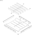
- FIG. 1 is a drawing illustrating the overall configuration of a pack case 100 according to the present invention
- FIG. 2 is an exploded perspective view of the pack case 100 according to the present invention.
- the present invention relates to a pack case 100 for storing a plurality of battery modules 200.
- the pack case 100 of the present invention includes a cooling plate 110, a side plate 120, a center frame 130, and a side beam 140.
- the cooling plate 110 forms the bottom of the pack case 100 and supports the load of the mounted battery modules 200. Additionally, the cooling plate 110 plays a crucial role in absorbing and cooling the heat from the battery module 200, as it widely contacts the entire bottom of the battery module 200.
- the cooling plate 110 may be made of a material with good thermal conductivity, for example, an aluminum alloy material, and may have a cooling flow path 112 inside it for effective cooling.
- a heat transfer medium, such as coolant, is circulated through the cooling flow path 112, and the heat transfer medium absorbs heat generated by the battery module 200 and dissipates it to the outside to maintain the temperature of the battery module 200 at a reasonable level.
- the side plate 120 refers to a plate member that is coupled to form a side wall at the edges of the cooling plate 110.
- the side plate 120 compartmentalizes the interior and exterior of the pack case 100, and the space for safely storing the battery module 200 is created by the cooling plate 110 and side plate 120.
- the center frame 130 is a member coupled to the cooling plate 110 to longitudinally divide the storing space formed by the side plate 120
- the side beam 140 is a member coupled to the cooling plate 110 to transversely divide the plurality of spaces divided by the center frame 130.
- the lattice structure formed by the center frame 130 and side beam 140 enhances the structural rigidity of the pack case 100 and also creates a plurality of individual storing spaces where each battery module 200 can be separately stored. In the illustrated embodiment, a total of eight individual storing spaces are provided by one center frame 130 and ten side beams 140, allowing the illustrated pack case 100 to mount eight battery modules 200.
- the cooling plate 110 absorbs and cools heat through the bottom of the battery module 200, it is desirable for the cooling plate 110 to be made of a material with excellent thermal conductivity for effective heat transfer.
- the cooling plate 110 with high thermal conductivity is effective in controlling the temperature of the battery module 200 under normal operation, there is a drawback that if thermal runaway occurs in any battery module 200, the excess heat rapidly spreads to other battery modules 200 through the cooling plate 110.
- the present invention configures the cooling plate 110 to be equipped with a slot 114 formed by penetrating along the coupling position of the center frame 130 or side beam 140.
- the center frame 130 and side beam 140 form boundaries between adjacent battery modules 200, and conductive heat transfer through the cooling plate 110 between battery modules 200 with the center frame 130 or side beam 140 in between is delayed by the slot 114. That is, part of the heat conduction path between the battery modules 200 through the cooling plate 110 is removed by the slot 114 formed by penetrating the cooling plate, reducing and delaying excessive heat transfer caused by a battery module 200 experiencing thermal runaway, thereby enhancing the safety of the battery pack 10.
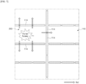
- FIG. 3 is a drawing illustrating the cooling plate 110, where in the illustrated embodiment, a plurality of slots 114 are formed on the cooling plate 110 and are spaced apart along the coupling position of the center frame 130 or side beam 140.
- the slot 114 can be formed along at least one of the coupling positions of the center frame 130 and side beam 140, and in the illustrated embodiment, they are formed at each coupling position of both the center frame 130 and side beam 140.
- each of the slot 114 is formed to a size that does not expose them beyond the center frame 130 and side beam 140. In other words, the width of the slot 114 is formed to be smaller than the thickness of the center frame 130 and side beam 140.
- the slot 114 is formed in a narrow, elongated shape. This shape of the slot 114 is considered to reduce the heat conduction through the cooling plate 110 without significantly compromising the structural rigidity and thermal capacity of the cooling plate 110, and the slot 114 can be provided in various shapes to meet this purpose depending on the embodiment.
- a plurality of slots 114 is dispersed in a row, with a fastening point 118 of the center frame 130 or side beam 140 formed in the spaces between the mutually spaced slots 114.
- the fastening point 118 refers to the point where the center frame 130 and side beams 140 are fixed to the cooling plate 110.
- Various known fastening structures can be applied to the fixing structure applied to the fastening point 118. For example, fastening methods such as bolting, forced fit with pins, welding, etc., can be applied.
- the fastening point 118 of the center frame 130 and side beam 140 can be distributed at both ends and in the middle of the plurality of slots 114 forming a row. By avoiding the slots 114 and distributing the fastening points 118 widely and evenly, the center frame 130 and side beam 140 can be securely fixed.
- the slot 114 is formed by penetrating the cooling plate 110 as a cooling flow path 112 is equipped inside the cooling plate 110, it is preferable to arrange the cooling flow path 112 and the slot 114 so that they do not overlap or intersect. This is considering the fact that preventing any leaked coolant from flowing out to the battery module 200 through the slot 114 and minimizing the heat transfer path around the slot 114 are advantageous in terms of delaying heat transfer.
- FIG. 4 is a drawing illustrating a battery pack 10 according to the present invention.
- the battery pack 10 provided by the present invention includes the pack case 100 described in the first embodiment, and the battery module 200 accommodated in each storing space divided longitudinally and transversely by the center frame 130 and side beam 140 of the pack case 100. In the illustrated embodiment, a total of eight battery modules 200 are gathered to form a single battery pack 10.
- FIG. 5 is a drawing illustrating another exemplary embodiment of the battery pack 10 of FIG. 4 .
- a thermal resin layer 210 is interposed in the contact surface between the battery module 200 and the cooling plate 110.
- the thermal resin layer 210 serves to mediate the transfer of heat from the battery module 200 to the cooling plate 110.
- the material forming the thermal resin layer 210 needs to be a resin material with excellent thermal conductivity.
- the thermal resin layer 210 is preferably formed with a thickness that is optimal for heat conduction while filling in micro-unevenness present on the contact surface between the battery module 200 and the cooling plate 110.
- the thermal resin layer 210 is preferably formed to the extent that it does not encroach on the slot 114. This is because the role of the slot 114 is to shrink and limit the heat conduction path between the battery modules 200, so if the thermal resin layer 210 is formed over the slot 114, the original role of the slot 114 is adversely affected.
- FIG. 6 is a cross-sectional view illustrating another exemplary embodiment of the battery pack 10 of FIG. 4 .
- an insulating material 116 is filled within the space created by the slot 114.
- the effectiveness of the slot 114 in blocking heat transfer can be enhanced by filling the slot 114 with an insulating material 116 that has a lower thermal conductivity than air.
- the insulating material 116 can more effectively block coolant that may leak from the cooling flow path 112, and it may also be desirable to fill the insulating material 116 with a flame retardant material in the slot 114 in case a fire occurs inside the battery pack 10.
- the battery pack 10 may further include a base plate 150 that couples to the bottom surface of the cooling plate 110.
- the base plate 150 serves to add structural rigidity to the bottom surface of the battery pack 10 and to protect the cooling plate 110 provided with the cooling flow path 112.
- the base plate 150 may include a base slot 152 corresponding to a slot 114 formed in the cooling plate 110. That is, the base slot 152 and the slot 114 of the cooling plate 110 are aligned to overlap upwardly and downwardly, and heat from the cooling plate 110 may be discharged to the outside through the base slot 152.
- FIG. 7 is a drawing illustrating heat transfer delay structure by a slot 114 formed in the cooling plate 110.
- a slot 114 penetrating through the cooling plate 110 is disposed along the coupling position of the center frame 130 and side beam 140. Since the center frame 130 and side beam 140 form a boundary between adjacent battery modules 200, the slots 114 formed along the boundary between the battery modules 200 serve to remove a portion of the heat conduction path between the battery modules 200 through the cooling plate 110. Accordingly, conduction heat transfer between the battery modules 200 on either side of the center frame 130 and/or the side beam 140 is significantly delayed by the slots 114, thereby improving the safety of the battery pack 10 by reducing and delaying excessive heat transfer to the surrounding area caused by a battery module 200 that has experienced thermal runaway.
- BATTERY PACK 100 PACK CASE 110: COOLING PLATE 112: COOLING FLOW PATH 114: SLOT 116: INSULATING MATERIAL 118: FASTENING POINT 120: SIDE PLATE 130: CENTER FRAME 140: SIDE BEAM 150: BASE PLATE 152: BASE SLOT 200: BATTERY MODULE 210: THERMAL RESIN LAYER
Landscapes
- Chemical & Material Sciences (AREA)
- Chemical Kinetics & Catalysis (AREA)
- Electrochemistry (AREA)
- General Chemical & Material Sciences (AREA)
- Engineering & Computer Science (AREA)
- Manufacturing & Machinery (AREA)
- Secondary Cells (AREA)
- Battery Mounting, Suspending (AREA)
- Aviation & Aerospace Engineering (AREA)
Abstract
Description
- The present invention relates to a battery pack that can delay thermal propagation between battery modules stored in a battery pack.
- This application claims the benefit of priority to
Korean Patent Application No. 10-2022-0113165, filed on September 7, 2022 - Unlike primary batteries, secondary batteries can be recharged, and they have been heavily researched and developed in recent years due to their potential for miniaturization and large capacity. The demand for secondary batteries as an energy source is increasing rapidly due to the technological development and increasing demand for mobile devices, electric vehicles, and energy storage systems, which are emerging in response to the need for environmental protection.
- Secondary batteries are categorized into coin-type cells, cylindrical cells, prismatic cells, and pouch-type cells based on the shape of the cell case. In a secondary battery, an electrode assembly mounted inside the battery case is a chargeable/dischargeable power generator consisting of a laminated structure of electrodes and separators.
- Since secondary batteries are required for continuous use over a long period, it is necessary to effectively control the heat generated during the charging and discharging process. If the cooling of the secondary battery is not carried out smoothly, the temperature rise can lead to an increase in current, and the increase in current can in turn cause a chain reaction of positive feedback, leading to a state of thermal runaway.
- Furthermore, when secondary batteries are grouped together in the form of modules or packs, thermal propagation occurs where heat generated in one secondary battery causes the surrounding secondary batteries to overheat successively. Moreover, the risk of fire is high due to flammable gasses released from overheated secondary batteries and ignition sources such as heated electrodes, hence there is a need to suppress such ignition risks.
- (Patent Document 001)
Korean Patent Publication No. 2022-0017741(published on February 21, 2022 - The present invention aims to provide a battery pack that can effectively suppress and prevent the phenomenon of thermal propagation in which heat transfer caused by thermal runaway generated by any secondary battery in a battery pack spreads to other secondary batteries or battery modules in the vicinity.
- However, the technical problems to be solved by the present invention are not limited to the above-described problem, and other problems not mentioned can be clearly understood by those skilled in the art from the following description of the present invention.
- The present invention relates to a pack case, where in one example, it includes a cooling plate equipped with a cooling flow path on the inside; a side plate coupled to form a side wall at the edge of the cooling plate; a center frame coupled to the cooling plate to longitudinally divide the storing space formed by the side plate; and a side beam coupled to the cooling plate to transversely divide a plurality of spaces divided by the center frame, wherein the cooling plate is provided with a slot formed by penetrating along the coupling position of the center frame or side beam.
- In an exemplary embodiment of the present invention, a plurality of the slots is spaced apart along the coupling position of the center frame or side beam.
In addition, the slot may be formed of a size that does not extend beyond the center frame and side beam. - In addition, a fastening point of the center frame or side beam is formed between the mutually spaced slots.
- Here, the fastening point may be distributed at both ends and in the middle of the plurality of slots forming a row.
- In addition, the cooling plate is characterized in that the cooling flow path and the slot may not overlap or intersect.
- In an exemplary embodiment of the present invention, an insulating material may be filled within the space formed by the slot, and the insulating material may be a watertight material.
- In addition, the pack case may further include a base plate coupled to the bottom surface of the cooling plate.
- The base plate may be provided with a base slot corresponding to the slot formed in the cooling plate.
- Meanwhile, the present invention provides a battery pack including: the pack case; and a battery module accommodated in each storing space divided longitudinally and transversely by the center frame and side beam of the pack case.
- In the battery pack of the present invention, a conductive heat transfer through the cooling plate between battery modules having the center frame or side beam in between is delayed by the slot.
- In addition, a thermal resin layer may be interposed at the contact surface between the battery module and the cooling plate, and it may be preferable that the thermal resin layer does not encroach upon the slot.
- The pack case and battery pack of the present invention, with the aforementioned configuration, have the advantage of enhanced safety, as part of the heat conduction path between battery modules through the cooling plate is eliminated by the penetrated slot, excessive heat transfer caused by the battery module experiencing thermal runaway is suppressed and delayed, and the safety of the battery pack is improved.
- However, the technical effects that can be obtained through this invention are not limited to those described above, and other effects not mentioned will be apparent to one of ordinary skill in the art from the following description of the invention.
- The following drawings accompanying this specification illustrate preferred exemplary embodiments of the present invention and are intended to serve as a further understanding of the technical ideas of the present invention in conjunction with the detailed description of the invention that follows, so the present invention is not to be construed as limited to what is shown in such drawings.
-
FIG. 1 is a drawing illustrating the overall configuration of a pack case according to the present invention. -
FIG. 2 is an exploded perspective view of a pack case according to the present invention. -
FIG. 3 is a drawing illustrating a cooling plate. -
FIG. 4 is a drawing illustrating a battery pack according to the present invention. -
FIG. 5 is a drawing illustrating another exemplary embodiment of the battery pack ofFIG. 4 . -
FIG. 6 is a cross-sectional view illustrating another exemplary embodiment of the battery pack ofFIG. 4 . -
FIG. 7 is a drawing illustrating heat transfer delay structure by a slot formed in a cooling plate. - The present invention may have various modifications and various examples, and specific examples are illustrated in the drawings and described in detail in the description.
- However, it should be understood that the present invention is not limited to specific embodiments, and includes all modifications, equivalents or alternatives within the spirit and technical scope of the present invention.
- The terms "comprise," "include" and "have" are used herein to designate the presence of characteristics, numbers, steps, actions, components or members described in the specification or a combination thereof, and it should be understood that the possibility of the presence or addition of one or more other characteristics, numbers, steps, actions, components, members or a combination thereof is not excluded in advance.
- In addition, when a part of a layer, a film, a region or a plate is disposed "on" another part, this includes not only a case in which one part is disposed "directly on" another part, but a case in which a third part is interposed there between. In contrast, when a part of a layer, a film, a region or a plate is disposed "under" another part, this includes not only a case in which one part is disposed "directly under" another part, but a case in which a third part is interposed there between. In addition, in this application, "on" may include not only a case of disposed on an upper part but also a case of disposed on a lower part.
- The present invention relates to a pack case capable of mounting a plurality of battery modules. In one example, the pack case includes a cooling plate equipped with a cooling flow path on the inside, a side plate coupled to form a side wall at the edge of the cooling plate, a center frame coupled to the cooling plate to longitudinally divide the storing space formed by the side plate, and a side beam coupled to the cooling plate to transversely divide a plurality of spaces divided by the center frame.
- Here, the cooling plate is provided with a slot formed by penetrating along the coupling position of the center frame or side beam.
- In the pack case of the present invention with such a configuration, the conductive heat transfer through the cooling plate between the battery modules with the center frame or the side beam in between is delayed by the slots. That is, part of the heat transfer path between the battery modules through the cooling plate is eliminated by the slots, so that the excessive heat transfer caused by the battery modules experiencing thermal runaway is suppressed and delayed, thereby improving the safety of the battery pack.
- Hereinafter, a detailed description will be given of specific embodiments of the secondary battery of the present invention with reference to the attached drawings. For reference, the relative positions specified in the directions of front and back, up and down, and left and right used in the following description are intended to aid in understanding the invention, and unless specially defined, are based on the directions shown in the drawings.
-
FIG. 1 is a drawing illustrating the overall configuration of apack case 100 according to the present invention, andFIG. 2 is an exploded perspective view of thepack case 100 according to the present invention. - The present invention relates to a
pack case 100 for storing a plurality ofbattery modules 200. Referring toFIG. 1 andFIG. 2 , thepack case 100 of the present invention includes acooling plate 110, aside plate 120, acenter frame 130, and aside beam 140. - The
cooling plate 110 forms the bottom of thepack case 100 and supports the load of the mountedbattery modules 200. Additionally, thecooling plate 110 plays a crucial role in absorbing and cooling the heat from thebattery module 200, as it widely contacts the entire bottom of thebattery module 200. For this purpose, thecooling plate 110 may be made of a material with good thermal conductivity, for example, an aluminum alloy material, and may have acooling flow path 112 inside it for effective cooling. A heat transfer medium, such as coolant, is circulated through thecooling flow path 112, and the heat transfer medium absorbs heat generated by thebattery module 200 and dissipates it to the outside to maintain the temperature of thebattery module 200 at a reasonable level. - The
side plate 120 refers to a plate member that is coupled to form a side wall at the edges of thecooling plate 110. Theside plate 120 compartmentalizes the interior and exterior of thepack case 100, and the space for safely storing thebattery module 200 is created by thecooling plate 110 andside plate 120. - The
center frame 130 is a member coupled to thecooling plate 110 to longitudinally divide the storing space formed by theside plate 120, and theside beam 140 is a member coupled to thecooling plate 110 to transversely divide the plurality of spaces divided by thecenter frame 130. The lattice structure formed by thecenter frame 130 andside beam 140 enhances the structural rigidity of thepack case 100 and also creates a plurality of individual storing spaces where eachbattery module 200 can be separately stored. In the illustrated embodiment, a total of eight individual storing spaces are provided by onecenter frame 130 and tenside beams 140, allowing the illustratedpack case 100 to mount eightbattery modules 200. - As mentioned earlier, since the
cooling plate 110 absorbs and cools heat through the bottom of thebattery module 200, it is desirable for thecooling plate 110 to be made of a material with excellent thermal conductivity for effective heat transfer. However, while thecooling plate 110 with high thermal conductivity is effective in controlling the temperature of thebattery module 200 under normal operation, there is a drawback that if thermal runaway occurs in anybattery module 200, the excess heat rapidly spreads toother battery modules 200 through thecooling plate 110. - In order to delay the heat transfer in the event of thermal runaway, the present invention configures the
cooling plate 110 to be equipped with aslot 114 formed by penetrating along the coupling position of thecenter frame 130 orside beam 140. Thecenter frame 130 andside beam 140 form boundaries betweenadjacent battery modules 200, and conductive heat transfer through thecooling plate 110 betweenbattery modules 200 with thecenter frame 130 orside beam 140 in between is delayed by theslot 114. That is, part of the heat conduction path between thebattery modules 200 through thecooling plate 110 is removed by theslot 114 formed by penetrating the cooling plate, reducing and delaying excessive heat transfer caused by abattery module 200 experiencing thermal runaway, thereby enhancing the safety of thebattery pack 10. -
FIG. 3 is a drawing illustrating thecooling plate 110, where in the illustrated embodiment, a plurality ofslots 114 are formed on thecooling plate 110 and are spaced apart along the coupling position of thecenter frame 130 orside beam 140. Theslot 114 can be formed along at least one of the coupling positions of thecenter frame 130 andside beam 140, and in the illustrated embodiment, they are formed at each coupling position of both thecenter frame 130 andside beam 140. Furthermore, each of theslot 114 is formed to a size that does not expose them beyond thecenter frame 130 andside beam 140. In other words, the width of theslot 114 is formed to be smaller than the thickness of thecenter frame 130 andside beam 140. - In the illustrated embodiment, the
slot 114 is formed in a narrow, elongated shape. This shape of theslot 114 is considered to reduce the heat conduction through thecooling plate 110 without significantly compromising the structural rigidity and thermal capacity of thecooling plate 110, and theslot 114 can be provided in various shapes to meet this purpose depending on the embodiment. - Referring to
FIG. 1 through FIG. 3 , a plurality ofslots 114 is dispersed in a row, with afastening point 118 of thecenter frame 130 orside beam 140 formed in the spaces between the mutually spacedslots 114. Thefastening point 118 refers to the point where thecenter frame 130 andside beams 140 are fixed to thecooling plate 110. Various known fastening structures can be applied to the fixing structure applied to thefastening point 118. For example, fastening methods such as bolting, forced fit with pins, welding, etc., can be applied. - Here, the
fastening point 118 of thecenter frame 130 andside beam 140 can be distributed at both ends and in the middle of the plurality ofslots 114 forming a row. By avoiding theslots 114 and distributing the fastening points 118 widely and evenly, thecenter frame 130 andside beam 140 can be securely fixed. - In addition, since the
slot 114 is formed by penetrating thecooling plate 110 as acooling flow path 112 is equipped inside thecooling plate 110, it is preferable to arrange thecooling flow path 112 and theslot 114 so that they do not overlap or intersect. This is considering the fact that preventing any leaked coolant from flowing out to thebattery module 200 through theslot 114 and minimizing the heat transfer path around theslot 114 are advantageous in terms of delaying heat transfer. -
FIG. 4 is a drawing illustrating abattery pack 10 according to the present invention. Thebattery pack 10 provided by the present invention includes thepack case 100 described in the first embodiment, and thebattery module 200 accommodated in each storing space divided longitudinally and transversely by thecenter frame 130 andside beam 140 of thepack case 100. In the illustrated embodiment, a total of eightbattery modules 200 are gathered to form asingle battery pack 10. -
FIG. 5 is a drawing illustrating another exemplary embodiment of thebattery pack 10 ofFIG. 4 . In the embodiment ofFIG. 5 , athermal resin layer 210 is interposed in the contact surface between thebattery module 200 and thecooling plate 110. Thethermal resin layer 210 serves to mediate the transfer of heat from thebattery module 200 to thecooling plate 110. For this purpose, the material forming thethermal resin layer 210 needs to be a resin material with excellent thermal conductivity. Furthermore, thethermal resin layer 210 is preferably formed with a thickness that is optimal for heat conduction while filling in micro-unevenness present on the contact surface between thebattery module 200 and thecooling plate 110. - Furthermore, the
thermal resin layer 210 is preferably formed to the extent that it does not encroach on theslot 114. This is because the role of theslot 114 is to shrink and limit the heat conduction path between thebattery modules 200, so if thethermal resin layer 210 is formed over theslot 114, the original role of theslot 114 is adversely affected. -
FIG. 6 is a cross-sectional view illustrating another exemplary embodiment of thebattery pack 10 ofFIG. 4 . Referring toFIG. 6 , an insulatingmaterial 116 is filled within the space created by theslot 114. The effectiveness of theslot 114 in blocking heat transfer can be enhanced by filling theslot 114 with an insulatingmaterial 116 that has a lower thermal conductivity than air. Furthermore, by configuring the insulatingmaterial 116 as a watertight material, the insulatingmaterial 116 can more effectively block coolant that may leak from thecooling flow path 112, and it may also be desirable to fill the insulatingmaterial 116 with a flame retardant material in theslot 114 in case a fire occurs inside thebattery pack 10. - And, as shown in
FIG. 6 , thebattery pack 10 may further include abase plate 150 that couples to the bottom surface of thecooling plate 110. Thebase plate 150 serves to add structural rigidity to the bottom surface of thebattery pack 10 and to protect thecooling plate 110 provided with thecooling flow path 112. - Depending on the embodiment, the
base plate 150 may include abase slot 152 corresponding to aslot 114 formed in thecooling plate 110. That is, thebase slot 152 and theslot 114 of thecooling plate 110 are aligned to overlap upwardly and downwardly, and heat from thecooling plate 110 may be discharged to the outside through thebase slot 152. -
FIG. 7 is a drawing illustrating heat transfer delay structure by aslot 114 formed in thecooling plate 110. Aslot 114 penetrating through thecooling plate 110 is disposed along the coupling position of thecenter frame 130 andside beam 140. Since thecenter frame 130 andside beam 140 form a boundary betweenadjacent battery modules 200, theslots 114 formed along the boundary between thebattery modules 200 serve to remove a portion of the heat conduction path between thebattery modules 200 through thecooling plate 110. Accordingly, conduction heat transfer between thebattery modules 200 on either side of thecenter frame 130 and/or theside beam 140 is significantly delayed by theslots 114, thereby improving the safety of thebattery pack 10 by reducing and delaying excessive heat transfer to the surrounding area caused by abattery module 200 that has experienced thermal runaway. - The present invention has been described in more detail above with reference to the drawings and embodiments. However, it is to be understood that the configurations shown in the drawings or embodiments described herein are only one embodiment of the invention and do not represent all of the technical ideas of the invention, and that there may be various equivalents and modifications that may replace them at the time of filing the present application.
-
10: BATTERY PACK 100: PACK CASE 110: COOLING PLATE 112: COOLING FLOW PATH 114: SLOT 116: INSULATING MATERIAL 118: FASTENING POINT 120: SIDE PLATE 130: CENTER FRAME 140: SIDE BEAM 150: BASE PLATE 152: BASE SLOT 200: BATTERY MODULE 210: THERMAL RESIN LAYER
Claims (15)
- A pack case comprising:a cooling plate equipped with a cooling flow path on the inside;a side plate coupled to form a side wall at the edge of the cooling plate;a center frame coupled to the cooling plate to longitudinally divide a storing space formed by the side plate; anda side beam coupled to the cooling plate to transversely divide a plurality of spaces divided by the center frame, whereinthe cooling plate is provided with a slot formed by penetrating along the coupling position of the center frame or side beam.
- The pack case of claim 1, wherein
the slot is formed by penetrating along the coupling position of the center frame and side beam. - The pack case of claim 1, wherein
a plurality of the slots is spaced apart along the coupling position of the center frame or side beam. - The pack case of claim 3, wherein
the slot is not exposed outside the center frame and side beam. - The pack case of claim 3, wherein
a fastening point of the center frame or side beam is formed between the mutually spaced slots. - The pack case of claim 5, wherein
the fastening point is distributed at both ends and in the middle of the plurality of slots forming a row. - The pack case of claim 1, wherein
the cooling plate is characterized in that the cooling flow path and the slot do not overlap or intersect. - The pack case of claim 1, wherein
an insulating material is filled within the space formed by the slot. - The pack case of claim 8, wherein
the insulating material is a watertight material. - The pack case of claim 1, further comprising:
a base plate coupled to the bottom surface of the cooling plate. - The pack case of claim 10, wherein
the base plate is provided with a base slot corresponding to the slot formed in the cooling plate. - A battery pack comprising:the pack case according to any one of claims 1 to 11; anda battery module accommodated in each storing space divided longitudinally and transversely by the center frame and side beam of the pack case.
- The battery pack of claim 12, wherein
a conductive heat transfer through the cooling plate between battery modules having the center frame or side beam in between is delayed by the slot. - The battery pack of claim 12, wherein
a thermal resin layer is interposed at the contact surface between the battery module and the cooling plate. - The battery pack of claim 14, wherein
the thermal resin layer does not encroach upon the slot.
Applications Claiming Priority (2)
| Application Number | Priority Date | Filing Date | Title |
|---|---|---|---|
| KR1020220113165A KR102676203B1 (en) | 2022-09-07 | 2022-09-07 | Battery pack having thermal propagation delay structure |
| PCT/KR2023/013120 WO2024053949A1 (en) | 2022-09-07 | 2023-09-04 | Battery pack having structure for delaying heat propagation |
Publications (2)
| Publication Number | Publication Date |
|---|---|
| EP4439805A1 true EP4439805A1 (en) | 2024-10-02 |
| EP4439805A4 EP4439805A4 (en) | 2025-07-09 |
Family
ID=90191438
Family Applications (1)
| Application Number | Title | Priority Date | Filing Date |
|---|---|---|---|
| EP23863424.0A Pending EP4439805A4 (en) | 2022-09-07 | 2023-09-04 | BATTERY PACK WITH STRUCTURE TO DELAY HEAT SPREAD |
Country Status (6)
| Country | Link |
|---|---|
| US (1) | US20250070320A1 (en) |
| EP (1) | EP4439805A4 (en) |
| JP (2) | JP7776652B2 (en) |
| KR (1) | KR102676203B1 (en) |
| CN (1) | CN118511365A (en) |
| WO (1) | WO2024053949A1 (en) |
Family Cites Families (15)
| Publication number | Priority date | Publication date | Assignee | Title |
|---|---|---|---|---|
| WO2013084938A1 (en) * | 2011-12-09 | 2013-06-13 | 本田技研工業株式会社 | Battery cooling structure |
| JP6252313B2 (en) * | 2014-03-31 | 2017-12-27 | 株式会社Gsユアサ | Power storage device |
| KR102740288B1 (en) * | 2017-01-12 | 2024-12-09 | 삼성에스디아이 주식회사 | Battery pack housing and battery pack including the same |
| JP2018170211A (en) * | 2017-03-30 | 2018-11-01 | 株式会社東芝 | Battery pack and battery module |
| KR102065099B1 (en) * | 2017-04-04 | 2020-01-10 | 주식회사 엘지화학 | Battery Pack having crash beam and drain structure |
| JP6922752B2 (en) * | 2018-01-15 | 2021-08-18 | トヨタ自動車株式会社 | Heat transfer components, battery packs, and vehicles |
| WO2020013120A1 (en) * | 2018-07-09 | 2020-01-16 | 三洋電機株式会社 | Battery system, electric vehicle equipped with battery system, and electricity storage device |
| KR102771554B1 (en) * | 2019-08-07 | 2025-02-20 | 주식회사 엘지에너지솔루션 | Battery pack that incorporates a battery module and a rigid beam and employs a reverse assembly |
| CN211629192U (en) * | 2020-04-23 | 2020-10-02 | 伟巴斯特车顶供暖系统(上海)有限公司 | A battery case and battery pack for a battery pack |
| KR20220017741A (en) | 2020-08-05 | 2022-02-14 | 주식회사 엘지에너지솔루션 | A battery module having a structure capable of absorbing battery cell swelling, and a battery pack and vehicle comprising the same |
| US11799149B2 (en) * | 2020-08-26 | 2023-10-24 | GM Global Technology Operations LLC | Energy storage assembly |
| KR102517890B1 (en) | 2021-02-05 | 2023-04-04 | 에스케이실트론 주식회사 | Demount stage for wafer and wafer polishing apparatus including the same |
| CN215342831U (en) * | 2021-05-06 | 2021-12-28 | 重庆长安新能源汽车科技有限公司 | Battery box, battery pack and vehicle for inhibiting thermal runaway of battery |
| CN113422139B (en) * | 2021-06-18 | 2022-05-31 | 中国第一汽车股份有限公司 | Battery assembly, electric vehicle and design method |
| US20230282903A1 (en) * | 2022-03-04 | 2023-09-07 | Sk On Co., Ltd. | Battery device |
-
2022
- 2022-09-07 KR KR1020220113165A patent/KR102676203B1/en active Active
-
2023
- 2023-09-04 CN CN202380016013.5A patent/CN118511365A/en active Pending
- 2023-09-04 US US18/726,401 patent/US20250070320A1/en active Pending
- 2023-09-04 JP JP2024538448A patent/JP7776652B2/en active Active
- 2023-09-04 EP EP23863424.0A patent/EP4439805A4/en active Pending
- 2023-09-04 WO PCT/KR2023/013120 patent/WO2024053949A1/en not_active Ceased
-
2025
- 2025-11-13 JP JP2025194404A patent/JP2026015498A/en active Pending
Also Published As
| Publication number | Publication date |
|---|---|
| US20250070320A1 (en) | 2025-02-27 |
| KR102676203B1 (en) | 2024-06-19 |
| JP2026015498A (en) | 2026-01-29 |
| CN118511365A (en) | 2024-08-16 |
| JP7776652B2 (en) | 2025-11-26 |
| JP2025500515A (en) | 2025-01-09 |
| KR20240034330A (en) | 2024-03-14 |
| WO2024053949A1 (en) | 2024-03-14 |
| EP4439805A4 (en) | 2025-07-09 |
Similar Documents
| Publication | Publication Date | Title |
|---|---|---|
| KR102814054B1 (en) | Bettery module | |
| EP4276983B1 (en) | Battery pack including pack case fitted with cooling fins | |
| US12087929B2 (en) | Battery module | |
| KR102065099B1 (en) | Battery Pack having crash beam and drain structure | |
| KR20230134660A (en) | Battery module and battery pack including the same | |
| KR20230131112A (en) | Battery module and battery pack including same | |
| KR102880677B1 (en) | Battery module and, battery pack and vehicle including same | |
| JP7723201B2 (en) | Battery packs and devices containing them | |
| KR102903646B1 (en) | Battery pack and vehicle including the same | |
| KR20230061158A (en) | Battery module and Battery pack including the same | |
| KR102799774B1 (en) | Battery pack and vehicle including the same | |
| KR102673791B1 (en) | Battery module and battery pack including the same | |
| KR20260051278A (en) | Battery module and battery pack including the same | |
| KR102852584B1 (en) | Battery pack and device including the same | |
| EP4322287A1 (en) | Secondary battery | |
| US20250070320A1 (en) | Battery pack having structure for delaying heat propagation | |
| KR102908854B1 (en) | Battery pack and device including the same | |
| EP4567983B1 (en) | Battery module with improved heat-dissipating structure and battery pack including same | |
| KR20250165015A (en) | Battery module and battery pack including the same | |
| KR20250138624A (en) | Battery assembly and battery pack including the same | |
| KR20250170303A (en) | Battery pack and device including the same | |
| KR20240016534A (en) | Battery module | |
| KR20240133100A (en) | Pack case having improved heat dissipation structure | |
| KR20250174878A (en) | Battery pack and device including the same | |
| KR20260049068A (en) | Battery pack and manufacturing method of the same |
Legal Events
| Date | Code | Title | Description |
|---|---|---|---|
| STAA | Information on the status of an ep patent application or granted ep patent |
Free format text: STATUS: THE INTERNATIONAL PUBLICATION HAS BEEN MADE |
|
| PUAI | Public reference made under article 153(3) epc to a published international application that has entered the european phase |
Free format text: ORIGINAL CODE: 0009012 |
|
| STAA | Information on the status of an ep patent application or granted ep patent |
Free format text: STATUS: REQUEST FOR EXAMINATION WAS MADE |
|
| 17P | Request for examination filed |
Effective date: 20240628 |
|
| AK | Designated contracting states |
Kind code of ref document: A1 Designated state(s): AL AT BE BG CH CY CZ DE DK EE ES FI FR GB GR HR HU IE IS IT LI LT LU LV MC ME MK MT NL NO PL PT RO RS SE SI SK SM TR |
|
| REG | Reference to a national code |
Ref country code: DE Ref legal event code: R079 Free format text: PREVIOUS MAIN CLASS: H01M0010658000 Ipc: H01M0010613000 |
|
| A4 | Supplementary search report drawn up and despatched |
Effective date: 20250610 |
|
| RIC1 | Information provided on ipc code assigned before grant |
Ipc: H01M 50/293 20210101ALI20250603BHEP Ipc: H01M 50/258 20210101ALI20250603BHEP Ipc: H01M 50/204 20210101ALI20250603BHEP Ipc: H01M 10/658 20140101ALI20250603BHEP Ipc: H01M 10/656 20140101ALI20250603BHEP Ipc: H01M 10/6555 20140101ALI20250603BHEP Ipc: H01M 10/613 20140101AFI20250603BHEP |
|
| DAV | Request for validation of the european patent (deleted) | ||
| DAX | Request for extension of the european patent (deleted) | ||
| STAA | Information on the status of an ep patent application or granted ep patent |
Free format text: STATUS: EXAMINATION IS IN PROGRESS |
|
| 17Q | First examination report despatched |
Effective date: 20260205 |