EP4439746A1 - Aqueous iodine-based battery based on multi-electron transfer - Google Patents
Aqueous iodine-based battery based on multi-electron transfer Download PDFInfo
- Publication number
- EP4439746A1 EP4439746A1 EP22902751.1A EP22902751A EP4439746A1 EP 4439746 A1 EP4439746 A1 EP 4439746A1 EP 22902751 A EP22902751 A EP 22902751A EP 4439746 A1 EP4439746 A1 EP 4439746A1
- Authority
- EP
- European Patent Office
- Prior art keywords
- concentration
- electrolyte
- battery
- positive
- negative
- Prior art date
- Legal status (The legal status is an assumption and is not a legal conclusion. Google has not performed a legal analysis and makes no representation as to the accuracy of the status listed.)
- Pending
Links
Images


Classifications
-
- H—ELECTRICITY
- H01—ELECTRIC ELEMENTS
- H01M—PROCESSES OR MEANS, e.g. BATTERIES, FOR THE DIRECT CONVERSION OF CHEMICAL ENERGY INTO ELECTRICAL ENERGY
- H01M10/00—Secondary cells; Manufacture thereof
- H01M10/02—Details
-
- H—ELECTRICITY
- H01—ELECTRIC ELEMENTS
- H01M—PROCESSES OR MEANS, e.g. BATTERIES, FOR THE DIRECT CONVERSION OF CHEMICAL ENERGY INTO ELECTRICAL ENERGY
- H01M10/00—Secondary cells; Manufacture thereof
- H01M10/36—Accumulators not provided for in groups H01M10/05-H01M10/34
-
- H—ELECTRICITY
- H01—ELECTRIC ELEMENTS
- H01M—PROCESSES OR MEANS, e.g. BATTERIES, FOR THE DIRECT CONVERSION OF CHEMICAL ENERGY INTO ELECTRICAL ENERGY
- H01M4/00—Electrodes
- H01M4/02—Electrodes composed of, or comprising, active material
- H01M4/13—Electrodes for accumulators with non-aqueous electrolyte, e.g. for lithium-accumulators; Processes of manufacture thereof
- H01M4/133—Electrodes based on carbonaceous material, e.g. graphite-intercalation compounds or CFx
-
- H—ELECTRICITY
- H01—ELECTRIC ELEMENTS
- H01M—PROCESSES OR MEANS, e.g. BATTERIES, FOR THE DIRECT CONVERSION OF CHEMICAL ENERGY INTO ELECTRICAL ENERGY
- H01M50/00—Constructional details or processes of manufacture of the non-active parts of electrochemical cells other than fuel cells, e.g. hybrid cells
- H01M50/40—Separators; Membranes; Diaphragms; Spacing elements inside cells
- H01M50/409—Separators, membranes or diaphragms characterised by the material
- H01M50/411—Organic material
- H01M50/414—Synthetic resins, e.g. thermoplastics or thermosetting resins
-
- H—ELECTRICITY
- H01—ELECTRIC ELEMENTS
- H01M—PROCESSES OR MEANS, e.g. BATTERIES, FOR THE DIRECT CONVERSION OF CHEMICAL ENERGY INTO ELECTRICAL ENERGY
- H01M4/00—Electrodes
- H01M4/02—Electrodes composed of, or comprising, active material
- H01M2004/026—Electrodes composed of, or comprising, active material characterised by the polarity
- H01M2004/028—Positive electrodes
-
- H—ELECTRICITY
- H01—ELECTRIC ELEMENTS
- H01M—PROCESSES OR MEANS, e.g. BATTERIES, FOR THE DIRECT CONVERSION OF CHEMICAL ENERGY INTO ELECTRICAL ENERGY
- H01M2300/00—Electrolytes
- H01M2300/0002—Aqueous electrolytes
- H01M2300/0005—Acid electrolytes
-
- Y—GENERAL TAGGING OF NEW TECHNOLOGICAL DEVELOPMENTS; GENERAL TAGGING OF CROSS-SECTIONAL TECHNOLOGIES SPANNING OVER SEVERAL SECTIONS OF THE IPC; TECHNICAL SUBJECTS COVERED BY FORMER USPC CROSS-REFERENCE ART COLLECTIONS [XRACs] AND DIGESTS
- Y02—TECHNOLOGIES OR APPLICATIONS FOR MITIGATION OR ADAPTATION AGAINST CLIMATE CHANGE
- Y02E—REDUCTION OF GREENHOUSE GAS [GHG] EMISSIONS, RELATED TO ENERGY GENERATION, TRANSMISSION OR DISTRIBUTION
- Y02E60/00—Enabling technologies; Technologies with a potential or indirect contribution to GHG emissions mitigation
- Y02E60/10—Energy storage using batteries
Definitions
- the present application relates to the field of battery, in particular to the field of multi-electron transfer aqueous iodine-based battery.
- the applicant has previously developed a multi-electron transfer aqueous iodine-based battery, in which I - in the positive electrolyte can electrochemically react to generate I 2 under a strong acidic environment, and the I 2 in turn charges to IO 3 - to realize a six-electron transfer. And the high solubility of I - enables a quantum leap in the energy density of the battery.
- the multi-electron transfer process faces serious electrochemical polarization problems.
- the electrochemical process of I 2 to generate IO 3 - needs to undergo a five-electron transfers and requires multiple H 2 O to participate in the reaction, and the positive charge center of symmetric I 2 is difficult to be attacked by the oxygen of H 2 O molecular, so that the charging reaction has a high polarization; for the discharging process, IO 3 - is structurally stable and has a large size, so that it is difficult to discharge directly on the electrode surface, and only indirect discharge can be achieved by oxidizing I - in the solution to form I 2 by IO 3 - .
- the electrode potential of I 2 /I - (0.54 V vs. SHE) is much lower than that of IO 3 - /I 2 (1.19 V vs. SHE), the discharging process is also highly polarized.
- Iodine based secondary battery based on multi-electron transfer comprising a positive electrolyte and a negative electrolyte, where the positive electrolyte and the negative electrolyte both comprise a strong acidic aqueous solutions containing Cd 2+ and I - , and a Br - and/or Cl - source additive, respectively.
- a source of the I - in the positive electrolyte and the negative electrolyte can be one or two or more of HI, KI, NaI, or CdI 2 , respectively; a source of the Cd 2+ can be one or two of CdI 2 or CdSO 4 , respectively; and a supporting electrolyte in the electrolytes can be selected from H 2 SO 4 to ensure a strong acidic environment.
- a molar concentration of Cd 2+ is from 0.5M to 3M
- a molar concentration of I - is from 1M to 6M
- a molar ratio of Cd 2+ to I - is 1:2 to 1:1
- a molar concentration of H + is from 3M to 12M, respectively; preferably, the molar ratio of Cd 2+ to I - is 1:2.
- IO - generated from I - at positive electrode can form a Cd(IO 3 ) 2 precipitate with Cd 2+ in the solution, thus solving a problem of self-discharge of the battery due to the infiltration of oxidized charging product IO 3 - .
- Additives are added to the positive electrolyte and the negative electrolyte to reduce the polarization problem in the electrochemical process, respectively, and the additives are mainly for the purpose of introducing Br - and/or Cl - .
- the Br - source additive can be one or two or more of NaBr, KBr or HBr; the Cl - source additive is one or two or more of NaCl, KCl or HCl; and a concentration of the introduced additives is from 1M to 3M.
- a composition of the positive electrolyte and the negative electrolyte are as follows respectively:
- the battery comprises a positive electrode, a negative electrode, a membrane material, and the electrolyte, where the electrolyte of positive and negative are strong acidic aqueous solutions containing Cd 2+ and I - , and the additive need to be introduced into the electrolyte to improve the kinetics and reversibility of an electrochemical reaction process;
- the membrane material of the battery is a polymer material, which is one or more of PES, PVC, PSF, PE, or Nafion, and preferably Nafion resin.
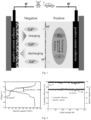
- the battery includes single cell or stacks; a structure of the single cell includes a positive terminal plate, a positive current collector, a positive carbon felt electrode filled with the positive electrolyte, a separator, a negative carbon felt electrode filled with the negative electrolyte, a negative current collector, and a negative terminal plate stacked in a sequential; the stack is composed of two or more single cell circuits in series and/or parallel.
- I - in the positive electrolyte When the battery is charged, I - in the positive electrolyte generates I 2 at the porous electrode and then continues to be charged to generate iodine interhalogen compounds such as IBr/ICl, and then continues to be charged and eventually generates IO 3 - and forms Cd(IO 3 ) 2 with Cd 2+ ; Cd 2+ in the negative electrolyte is reduced to metal Cd.
- the discharging process at the positive electrode is an indirect discharge of Cd(IO 3 ) 2 through a chemical-oxidation-electrochemical reaction and finally discharge to generate I - ; while the discharging reaction at the negative electrode is the generation of Cd 2+ from metal Cd.
- the present invention introduces other halogen ions (Br - or Cl - ) as additives in the electrolyte, which can well improve the electrochemical activity and reversibility of the electrolyte.
- the formation of interhalogen compounds (IBr/ICl) between halogens with different electronegativities (I 2 and Br 2 or I 2 and Cl 2 ) facilitates the attack of water molecules on the positive charge centers, and thus reducing the polarization of the charging.
- Cl - or Br - is introduced into the solution as an additive, and I 2 is able to generate interhalogen compounds, such as ICl or IBr, with Br 2 or Cl 2 during the electrochemical reaction; compared to the symmetric molecule I 2 , the positive charge of ICl or IBr is mainly concentrated on iodine atoms, and therefore, during the charging process, the oxygen atoms of H 2 O are more likely to attack them thereby favoring the generation of IO 3 - , and the generated IO 3 - can form Cd(IO 3 ) 2 with Cd 2+ , thus avoiding self-discharge caused by the infiltration of IO 3 - and reducing the electrochemical polarization of charging.
- interhalogen compounds such as ICl or IBr
- the positive charge of ICl or IBr is mainly concentrated on iodine atoms, and therefore, during the charging process, the oxygen atoms of H 2 O are more likely to attack them thereby favoring the generation of
- IO 3 - chemically oxidizes other halogen ions such as Cl - /Br - to from IBr, Br 2 or ICl, Cl 2 , and in turn, indirect discharge can be realized by the reduction of IBr, Br 2 or ICl, Cl 2 on the electrode surface.
- halogens with higher electronegativity have higher electrode potentials, e.g., the electrode potential of Br 2 /Br - is about 1.08 V, which is slightly lower than the electrode potential of I 2 /IO 3 - of 1.19 V Therefore, the IO 3 - can easily oxidize Br - to monomeric bromine, and the potential difference between the two is relatively small (much smaller than the potential difference between IO 3 - /I 2 (1.19V vs. SHE) and I 2 /I - (0.54 V vs. SHE)), which can effectively reduce the discharge polarization of the battery.
- the system realizes a reversible six-electron transfer reaction of I - /IO 3 - in a strong acidic medium, which leads to an extremely high energy density by increasing the electron transfer number and combining it with a high concentration of electrolyte.
- Performance testing of a multi-electron transfer iodine-based aqueous battery was conducted with a charging current density of 80 mA/cm 2 , one or both of a battery charging cut-off voltage of 2.4 V or a specific capacity, and a discharge cut-off voltage of 0.1 V
- the carbon felts on both sides of the positive and negative electrodes of the battery were 1 mm, with a surface area of 48 cm 2 , and the volume of electrolyte on the positive side of the battery was 5 mL, and on the negative side of the battery was 15 mL, where the electrolyte on both sides of the battery was adsorbed inside the porous carbon felts.
- the membrane material for the battery is Nafion 115 membrane. The positive and negative electrolytes are the same.
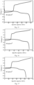
- Fig. 2 to Fig.5 show the charging and discharging curves and cycle performance tests of the battery under the optimal conditions; as the electrolyte concentration increases, the energy density of the battery rises to 1100 Wh/L from 220 Wh/L at 1M.
- the battery can operate stably for a maximum of more than 500 cycles.
- the energy density of the battery is about 1100 Wh/L, and the efficiency exceeds 74%. This indicates that the most preferred electrolyte has a significant advantage in terms of energy density.
- Reducing the concentration of H + in the solution will also decrease the performance of the battery, mainly because the reduction in the concentration of H + causes a decrease in the oxidizability of IO 3 - in the electrolyte, which decrease the rate of oxidizing Br - in the solution (Comparative Examples 4-5; Figs. 18-19 ).
- the efficiency of the battery By reducing the concentration of I - in the solution, the efficiency of the battery also significantly decreases. This is mainly because as the concentration of I - decreases, the rate of IO 3 - chemical oxidizing Br- or Cl- in the electrolyte during charging and discharging is limited. Therefore, the energy efficiency of the battery is only about 64% (Comparative Example 6; Fig. 20 ).
- Table 1 Examples of iodine based multi-electron transfer battery system Examples Composition of electrolyte (mol/L) Energy density (Wh/L) Current density (mA/cm 2 ) Membrane material Energy efficiency EE(%) 1 0.5M CdI 2 , 1M HBr, 3M H 2 SO 4 220 80 Nafion 115 78% 2 1M CdI 2 , 2M HBr, 3M H 2 SO 4 350 80 Nafion 115 77% 3 3M CdI 2 , 3M HBr, 3M H 2 SO 4 1100 40 Nafion115 75% 4 3M HI, 1.5M CdSO 4 , 3M HBr, 3M H 2 SO 4 490 80 Nafion115 76% 5 1M CdI 2 , 2M NaBr, 3M H 2 SO 4 350 80 Nafion115 76% 6 1M CdI 2 , 2M NaCl, 3M H 2 SO 4 340 80 Nafion115 76% 7
Landscapes
- Chemical & Material Sciences (AREA)
- Chemical Kinetics & Catalysis (AREA)
- Electrochemistry (AREA)
- General Chemical & Material Sciences (AREA)
- Engineering & Computer Science (AREA)
- Manufacturing & Machinery (AREA)
- Materials Engineering (AREA)
- Secondary Cells (AREA)
- Cell Separators (AREA)
Abstract
Description
- The present application relates to the field of battery, in particular to the field of multi-electron transfer aqueous iodine-based battery.
- The large-scale utilization of fossil energy has caused environmental pollution and energy crisis; therefore, the development and utilization of renewable energy is the key to solve the above problems. The promotion of electric vehicles is an important means to solve the fossil energy crisis. But at present, lithium-ion batteries are mainly use in electric vehicles; although the energy density of lithium-ion batteries is very high (about 300 Wh/L), but due to the use of organic electrolyte, it will bring about flammable and explosive problems. Aqueous batteries have good application prospects due to their high safety and power density. However, at present, the energy density of aqueous batteries is generally low, thus making it difficult to be used in the field of power batteries. The applicant has previously developed a multi-electron transfer aqueous iodine-based battery, in which I- in the positive electrolyte can electrochemically react to generate I2 under a strong acidic environment, and the I2 in turn charges to IO3 - to realize a six-electron transfer. And the high solubility of I- enables a quantum leap in the energy density of the battery. However, the multi-electron transfer process faces serious electrochemical polarization problems. In the charging process, the electrochemical process of I2 to generate IO3 - needs to undergo a five-electron transfers and requires multiple H2O to participate in the reaction, and the positive charge center of symmetric I2 is difficult to be attacked by the oxygen of H2O molecular, so that the charging reaction has a high polarization; for the discharging process, IO3 - is structurally stable and has a large size, so that it is difficult to discharge directly on the electrode surface, and only indirect discharge can be achieved by oxidizing I- in the solution to form I2 by IO3 -. However, since the electrode potential of I2/I- (0.54 V vs. SHE) is much lower than that of IO3 -/I2 (1.19 V vs. SHE), the discharging process is also highly polarized.
- Iodine based secondary battery based on multi-electron transfer comprising a positive electrolyte and a negative electrolyte, where the positive electrolyte and the negative electrolyte both comprise a strong acidic aqueous solutions containing Cd2+ and I-, and a Br- and/or Cl- source additive, respectively.
- A source of the I- in the positive electrolyte and the negative electrolyte can be one or two or more of HI, KI, NaI, or CdI2, respectively; a source of the Cd2+ can be one or two of CdI2 or CdSO4, respectively; and a supporting electrolyte in the electrolytes can be selected from H2SO4 to ensure a strong acidic environment.
- In the positive electrolyte or negative electrolyte, a molar concentration of Cd2+ is from 0.5M to 3M, a molar concentration of I- is from 1M to 6M, a molar ratio of Cd2+ to I- is 1:2 to 1:1, and a molar concentration of H+ is from 3M to 12M, respectively; preferably, the molar ratio of Cd2+ to I- is 1:2.
- During charging process, IO- generated from I- at positive electrode can form a Cd(IO3)2 precipitate with Cd2+ in the solution, thus solving a problem of self-discharge of the battery due to the infiltration of oxidized charging product IO3 -.
- Additives are added to the positive electrolyte and the negative electrolyte to reduce the polarization problem in the electrochemical process, respectively, and the additives are mainly for the purpose of introducing Br- and/or Cl-. The Br- source additive can be one or two or more of NaBr, KBr or HBr; the Cl- source additive is one or two or more of NaCl, KCl or HCl; and a concentration of the introduced additives is from 1M to 3M.
- A composition of the positive electrolyte and the negative electrolyte are as follows respectively:
- HI used as an iodine-based active substance with a concentration of 1M to 6M (preferably 6M); HBr and/or HCl used as additive with a concentration of 1M to 3M (preferably 3M); H2SO4 used as a support electrolyte with a concentration of 1M to 3M (preferably 1M); Cd(SO4)2 used as an active substance of Cd with a concentration of 1M to 3M (preferably 3M); or
- HI used as an iodine-based active substance with a concentration of 1M to 6M (preferably 6M); one or two or more of NaBr, KBr, NaCl, and KCl used as additive with a concentration of 1M to 3M (preferably 3M); H2SO4 used as a support electrolyte with a concentration of 2M to 4M (preferably 2M); Cd(SO4)2 used as an active substance of Cd with a concentration of 1M to 3M (preferably 3M); or
- CdI2 used as an active substance with a concentration of 0.5M to 3M (preferably 3M); HBr and/or HCl used as additive with a concentration of 1M to 3M (preferably 3M); H2SO4 used as a support electrolyte with a concentration of 2M to 4M (preferably 4M); or
- CdI2 used as an active substance with a concentration of 0.5M to 3M (preferably 3M); one or two or more of NaBr, KBr, NaCl, and KCl used as additive with a concentration of 1M to 3M (preferably 3M); H2SO4 used as a support electrolyte with a concentration of 3M to 5M (preferably 5M); or
- NaI and/or KI used as an active substance with a concentration of 1M to 6M (preferably 6M); HBr and/or HCl used as additive with a concentration of 1M to 3M (preferably 3M); H2SO4 used as a support electrolyte with a concentration of 2M to 4M (preferably 4M); Cd(SO4)2 used as an active substance of Cd with a concentration of 1M to 3M (preferably 3M); or
- NaI and/or KI used as an active substance with a concentration of 1M to 6M (preferably 6M); one or two or more of NaBr, KBr, NaCl, and KCl used as additive with a concentration of 1M to 3M (preferably 3M); H2SO4 used as a support electrolyte with a concentration of 3M to 5M (preferably 5M); Cd(SO4)2 used as an active substance of Cd with a concentration of 1M to 3M (preferably 3M).
- The battery comprises a positive electrode, a negative electrode, a membrane material, and the electrolyte, where the electrolyte of positive and negative are strong acidic aqueous solutions containing Cd2+ and I-, and the additive need to be introduced into the electrolyte to improve the kinetics and reversibility of an electrochemical reaction process; the membrane material of the battery is a polymer material, which is one or more of PES, PVC, PSF, PE, or Nafion, and preferably Nafion resin.
- The battery includes single cell or stacks; a structure of the single cell includes a positive terminal plate, a positive current collector, a positive carbon felt electrode filled with the positive electrolyte, a separator, a negative carbon felt electrode filled with the negative electrolyte, a negative current collector, and a negative terminal plate stacked in a sequential; the stack is composed of two or more single cell circuits in series and/or parallel.
- When the battery is charged, I- in the positive electrolyte generates I2 at the porous electrode and then continues to be charged to generate iodine interhalogen compounds such as IBr/ICl, and then continues to be charged and eventually generates IO3 - and forms Cd(IO3)2 with Cd2+; Cd2+ in the negative electrolyte is reduced to metal Cd. For the discharging process, the discharging process at the positive electrode is an indirect discharge of Cd(IO3)2 through a chemical-oxidation-electrochemical reaction and finally discharge to generate I-; while the discharging reaction at the negative electrode is the generation of Cd2+ from metal Cd.
- Beneficial effects that can be produced by the present application include:
The present invention introduces other halogen ions (Br- or Cl-) as additives in the electrolyte, which can well improve the electrochemical activity and reversibility of the electrolyte. The formation of interhalogen compounds (IBr/ICl) between halogens with different electronegativities (I2 and Br2 or I2 and Cl2) facilitates the attack of water molecules on the positive charge centers, and thus reducing the polarization of the charging. For example, Cl- or Br- is introduced into the solution as an additive, and I2 is able to generate interhalogen compounds, such as ICl or IBr, with Br2 or Cl2 during the electrochemical reaction; compared to the symmetric molecule I2, the positive charge of ICl or IBr is mainly concentrated on iodine atoms, and therefore, during the charging process, the oxygen atoms of H2O are more likely to attack them thereby favoring the generation of IO3 -, and the generated IO3 - can form Cd(IO3)2 with Cd2+, thus avoiding self-discharge caused by the infiltration of IO3 - and reducing the electrochemical polarization of charging. For the discharging process, IO3 - chemically oxidizes other halogen ions such as Cl-/Br-to from IBr, Br2 or ICl, Cl2, and in turn, indirect discharge can be realized by the reduction of IBr, Br2 or ICl, Cl2 on the electrode surface. In addition, halogens with higher electronegativity have higher electrode potentials, e.g., the electrode potential of Br2/Br- is about 1.08 V, which is slightly lower than the electrode potential of I2/IO3 - of 1.19 V Therefore, the IO3 - can easily oxidize Br- to monomeric bromine, and the potential difference between the two is relatively small (much smaller than the potential difference between IO3 -/I2 (1.19V vs. SHE) and I2/I- (0.54 V vs. SHE)), which can effectively reduce the discharge polarization of the battery. The system realizes a reversible six-electron transfer reaction of I-/IO3 - in a strong acidic medium, which leads to an extremely high energy density by increasing the electron transfer number and combining it with a high concentration of electrolyte. -
-
Fig. 1 is a structure diagram of a multi-electron transfer aqueous iodine-based battery system. -
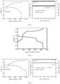
Fig. 2 shows the charge/discharge curves and cycle performance of the assembled battery of Example 1. The composition of the electrolytes is 0.5M CdI2+3M H2SO4+IM HBr. The working current density of the battery is 80 mA/cm2 and the membrane material is Nafion 115 membrane. The energy density of the battery at a current density of 80 mA/cm2 is more than 220 Wh/L, and the energy efficiency is more than 77%; and the battery can run stably for more than 500 cycles with an energy density of 100 Wh/L. The structure of the battery mainly includes: a positive terminal plate, a positive current collector, a positive electrode, a separator, a negative electrode, a negative current collector, and a negative terminal plate. The test conditions of the battery are as follows: charging cut-off condition is double cut-off of voltage and capacity, and discharging cut-off condition is 0.1 V voltage. The charging and discharging processes of the battery are constant current charging and discharging. -
Fig. 3 shows the charge/discharge curves and cycle performance of the assembled battery of Example 2. The composition of the electrolytes is 1M CdI2+3M H2SO4+2M HBr. The working current density of the battery is 80 mA/cm2 and the membrane material is Nafion 115 membrane. The energy density of the battery at a current density of 80 mA/cm2 is more than 350 Wh/L, and the energy efficiency is more than 77%; and the battery can run stably for more than 400 cycles with an energy density of 220 Wh/L. -
Fig. 4 shows the charge/discharge curves and cycle performance of the assembled battery of Example 3. The composition of the electrolytes is 3M CdI2+3M H2SO4+3M HBr and the membrane material is Nafion 115 membrane. The battery can achieve an energy density of over 1100 Wh/L at 40 mA/cm2 and an energy efficiency of over 75%. -
Fig. 5 shows the charge/discharge curves and cycle performance of the assembled battery of Example 4. The composition of the electrolytes is 3M HI+1.5M CdSO4+3M H2SO4+3M HBr, and the membrane material is Nafion 115 membrane. The battery can achieve an energy density of over 490 Wh/L at 80 mA/cm2 and an energy efficiency of over 76%; and the battery can run stably for more than 120 cycles with an energy density of 320 Wh/L. -
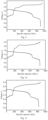
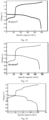
Fig. 6 shows the charge/discharge curves of the assembled battery of Example 5. The composition of the electrolytes is 1M CdI2+3M H2SO4+2M NaBr and the membrane material is Nafion 115 membrane. The battery can achieve an energy density of over 350 Wh/L at 80 mA/cm2 and an energy efficiency of over 76%. -
Fig. 7 shows a graph of the performance of the assembled battery of Example 6. The composition of the electrolytes is 1M CdI2+3M H2SO4+2M NaCl, the additive was changed from Br- to Cl-, and the membrane material is Nafion 115 membrane. The battery can achieve an energy density of over 340 Wh/L at 80 mA/cm2 and an energy efficiency of over 76%. -
Fig. 8 shows a graph of the performance of the assembled battery of Example 7. The composition of the electrolytes is 1M CdI2+3M H2SO4+2M HCl, and the membrane material is Nafion 115 membrane. The battery can achieve an energy density of over 345 Wh/L at 80 mA/cm2 and an energy efficiency of over 76%. -
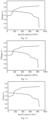
Fig. 9 shows a graph of performance of the assembled battery of Preferred Example 1. The composition of the electrolytes is 6M HI+3M HBr+1M H2SO4+3M CdSO4, and the membrane material is Nafion 115 membrane. The battery can achieve an energy density of over 1050 Wh/L at 80 mA/cm2 and an energy efficiency of over 74%. -
Fig. 10 shows a graph of performance of the assembled battery of Preferred Example 2. The composition of the electrolytes is 6M HI+3M KCl+2M H2SO4+3M CdSO4, and the membrane material is Nafion 115 membrane. The battery can achieve an energy density of over 1020 Wh/L at 80 mA/cm2 and an energy efficiency of over 75%. -
Fig. 11 shows a graph of performance of the assembled battery of Preferred Example 3. The composition of the electrolytes is 6M NaI+3M HBr+4M H2SO4+3M CdSO4, and the membrane material is Nafion 115 membrane. The battery can achieve an energy density of over 1060 Wh/L at 80 mA/cm2 and an energy efficiency of over 74%. -
Fig. 12 shows a graph of performance of the assembled battery of Preferred Example 4. The composition of the electrolytes is 6M NaI+3M NaBr+5M H2SO4+3M CdSO4, and the membrane material is Nafion 115 membrane. The battery can achieve an energy density of over 1045 Wh/L at 80 mA/cm2 and an energy efficiency of over 76%. -
Fig. 13 shows a graph of performance of the assembled battery of Preferred Example 5. The composition of the electrolytes is 6M KI+3M HBr+4M H2SO4+3M CdSO4, and the membrane material is Nafion 115 membrane. The battery can achieve an energy density of over 1074 Wh/L at 80 mA/cm2 and an energy efficiency of over 74%. -
Fig. 14 shows a graph of performance of the assembled battery of Preferred Example 6. The composition of the electrolytes is 6M KI+3M HBr+4M H2SO4+3M CdSO4, and the membrane material is Nafion 115 membrane. The battery can achieve an energy density of over 1022 Wh/L at 80 mA/cm2 and an energy efficiency of over 74%. -
Fig. 15 shows the performance test chart of the multi-electron transfer iodine-based battery assembled in Comparative Example 1. The composition of the electrolytes is 0.5M CdI2+3M H2SO4, the working current density of the battery is 80 mA/cm2 and the membrane material is Nafion 115 membrane. However, the polarization of the battery is very severe, with an energy efficiency of only 57%, and due to the influence of polarization, the energy density of the battery is relatively low, only 114 Wh/L. -
Fig. 16 shows the performance test chart of the multi-electron transfer iodine-based battery assembled in Comparative Example 2. The composition of the electrolytes is 0.5M CdI2+3M H2SO4+0.1M HBr, the working current density of the battery is 80 mA/cm2 and the membrane material is Nafion 115 membrane. Due to the low concentration of HBr, the polarization of the battery is severe, and the energy efficiency is only 54%, and the energy density of the battery is limited, only 104 Wh/L. -
Fig. 17 shows the performance test chart of the battery assembled in Comparative Example 3. The composition of the electrolytes is 1M HI+3M H2SO4+1M HBr+0.2M CdSO4. The working current density of the battery is 80 mA/cm2 and the membrane material is Nafion 115 membrane. Due to Cd2+: I-=1:5 in the solution, the generated IO3 - cannot form Cd(IO3)2 precipitate with Cd2+, resulting in severe electrolyte crossover. Therefore, the Coulombic efficiency of the battery is relatively low, with an energy efficiency of nearly 60% and an energy density of only about 103 Wh/L. -
Fig. 18 shows the performance test chart of the battery assembled in Comparative Example 4. The composition of the electrolytes is 0.5M CdI2+1M HBr. The working current density of the battery is 80 mA/cm2 and the membrane material is Nafion 115 membrane. Although HBr is added as an additive, the low concentration of H+ in the solution will affect the chemical reaction rate of IO3 - oxidizing Br-, ultimately affecting the energy efficiency of the battery. The test results show that the energy efficiency of the battery at 80 mA/cm2 is only 65% and the energy density is lower than 150 Wh/L. -
Fig. 19 shows the performance test chart of the battery assembled in Comparative Example 5. The composition of the electrolytes is 0.5M CdI2+0.5M H2SO4+1M HBr. The working current density of the battery is 80 mA/cm2 and the membrane material is Nafion 115 membrane. Similar to Comparative Example 4, although HBr is added as an additive and some H2SO4 is added as a supporting electrolyte, the H+ concentration is still low, so the reaction rate of IO3 - oxidizing Br-is slow, and as a result, the polarization of the battery is still severe and the efficiency of the battery is only 70%. -
Fig. 20 shows the performance test chart of the battery assembled in Comparative Example 6. The composition of the electrolytes is 0.1M CdI2+3M H2SO4+1M HBr. The working current density of the battery is 80 mA/cm2 and the membrane material is Nafion 115 membrane. However, in this electrolyte system, due to the low concentration of CdI2, less IO3 - is generated, for which it is difficult to chemically react with Br- during discharging to achieve indirect discharge. Therefore, the polarization of the battery is still relatively high. The test results show that at 80 mA/cm2, the energy efficiency of the battery is only 64%. -
Fig. 21 shows the performance test chart of the battery assembled in Comparative Example 7. The composition of the electrolytes is 0.5M CdI2+3M H2SO4+1M HBr. The working current density of the battery is 80 mA/cm2 and the membrane material is PE porous film. Compared to Nafion 115 membrane, PE porous membrane has a weaker barrier ability to the positive electrode charging products, resulting in severe infiltration of the positive electrolyte and low Coulombic efficiency of the battery. The test results of the battery indicate that the energy density of the battery is only 52%. -
Fig. 22 shows the performance test chart of the battery assembled in Comparative Example 8. The composition of the electrolytes is 1M HI+3M H2SO4+1M TiOSO4. The working current density of the battery is 80 mA/cm2 and the membrane material is Nafion 115 membrane. Compared to the Cd2+/Cd negative electrode, the Ti3+/Ti4+ electrode used as the negative electrode of the battery has very poor performance. This is mainly due to the low activity of TiO(IO3)2 generated by IO3 - and TiO2+, making it difficult to oxidize Br-, and the energy efficiency of the battery is only 32%. - Performance testing of a multi-electron transfer iodine-based aqueous battery was conducted with a charging current density of 80 mA/cm2, one or both of a battery charging cut-off voltage of 2.4 V or a specific capacity, and a discharge cut-off voltage of 0.1 V The carbon felts on both sides of the positive and negative electrodes of the battery were 1 mm, with a surface area of 48 cm2, and the volume of electrolyte on the positive side of the battery was 5 mL, and on the negative side of the battery was 15 mL, where the electrolyte on both sides of the battery was adsorbed inside the porous carbon felts. The membrane material for the battery is Nafion 115 membrane. The positive and negative electrolytes are the same.
-
Fig. 2 to Fig.5 (Examples 1-4) show the charging and discharging curves and cycle performance tests of the battery under the optimal conditions; as the electrolyte concentration increases, the energy density of the battery rises to 1100 Wh/L from 220 Wh/L at 1M. In addition, by maintaining a constant capacity of four electrons for charging and discharging, the battery can operate stably for a maximum of more than 500 cycles. - Compared to electrolytes with HBr as an additive, replacing HBr in the solution with NaBr, HCl, or NaCl (corresponding to
Fig. 6 to Fig. 8 in Examples 5-7) can also achieve higher electrochemical activity. This is mainly due to the formation of iodine interhalogen compounds IBr/ICl during the charging process, which can also reduce charging polarization. For the discharging process, IO3 - can oxidize Br-/Cl- to achieve indirect discharge and increase the discharge voltage of the battery. Therefore, the energy efficiency of the electrolyte system with the above additives can also achieve an energy efficiency of >75%. - Increasing the concentration of the electrolyte to 6M (the most preferred electrolyte composition, Preferred Examples 1-6, corresponding to
Fig.9 to Fig.14 ), the energy density of the battery is about 1100 Wh/L, and the efficiency exceeds 74%. This indicates that the most preferred electrolyte has a significant advantage in terms of energy density. - Compared to electrolyte systems with additives, electrolytes with lower additive concentrations or without additives exhibit severe polarization, the performance of the battery is lower (Comparative Examples 1-2;
Fig 15 and 16 ), and the energy efficiency of the battery is less than 60%. - Compared with the electrolyte systems with a higher concentration of Cd2+, the low concentration of Cd2+ makes it difficult to completely precipitate with IO3 - in the solution; the self-discharge of the battery is serious, the performance of the battery is low (Comparative Example 3;
Fig. 17 ), and the energy efficiency of the battery is lower than 60%. - Reducing the concentration of H+ in the solution will also decrease the performance of the battery, mainly because the reduction in the concentration of H+ causes a decrease in the oxidizability of IO3 - in the electrolyte, which decrease the rate of oxidizing Br- in the solution (Comparative Examples 4-5;
Figs. 18-19 ). - By reducing the concentration of I- in the solution, the efficiency of the battery also significantly decreases. This is mainly because as the concentration of I- decreases, the rate of IO3 -chemical oxidizing Br- or Cl- in the electrolyte during charging and discharging is limited. Therefore, the energy efficiency of the battery is only about 64% (Comparative Example 6;
Fig. 20 ). - Replacing Nafion 115 membrane with PE polyolefin porous membrane resulted in a low Coulombic efficiency of the battery due to severe electrolyte crossover (Comparative Example 7;
Fig. 21 ). - By replacing the Cd2+/Cd negative electrode of the battery with Ti3+/Ti4+, the IO3 - generated from I- oxidation generate TiO(IO3)2 with TiO2+. Due to the slow rate of chemical oxidation of Br-or Cl- by TiO(IO3)2, the efficiency and energy density of the battery are low (Comparative Example 8;
Fig. 22 ).Table 1: Examples of iodine based multi-electron transfer battery system Examples Composition of electrolyte (mol/L) Energy density (Wh/L) Current density (mA/cm2) Membrane material Energy efficiency EE(%) 1 0.5M CdI2, 1M HBr, 3M H2SO4 220 80 Nafion 115 78% 2 1M CdI2, 2M HBr, 3M H2SO4 350 80 Nafion 115 77% 3 3M CdI2, 3M HBr, 3M H2SO4 1100 40 Nafion115 75% 4 3M HI, 1.5M CdSO4, 3M HBr, 3M H2SO4 490 80 Nafion115 76% 5 1M CdI2, 2M NaBr, 3M H2SO4 350 80 Nafion115 76% 6 1M CdI2, 2M NaCl, 3M H2SO4 340 80 Nafion115 76% 7 1M CdI2, 2M HCl, 3M H2SO4 345 80 Nafion115 76% Table 2: Preferred examples of iodine based multi-electron transfer battery system Preferred examples Composition of electrolyte (mol/L) Energy density (Wh/L) Working current density (mA/cm2) Membrane material Energy efficiency EE(%) 1 6M HI, 3M HBr, 1M H2SO4, 3M CdSO4 1050 80 Nafion115 74% 2 6M HI, 3M KCl, 2M H2SO4, 3M CdSO4 1020 80 Nafion115 75% 3 6M NaI, 3M HBr, 4M H2SO4, 3M CdSO4 1060 80 Nafion115 74% 4 6M NaI, 3M NaBr, 5M H2SO4, 3M CdSO4 1045 80 Nafion115 76% 5 6M KI, 3M HBr, 4M H2SO4, 3M CdSO4 1074 80 Nafion115 74% 6 6M KI, 3M HBr, 4M H2SO4, 3M CdSO4 1022 80 Nafion115 74% Table 3: Comparative examples of iodine based multi-electron transfer battery system Comparative examples Composition of electrolyte (mol/L) Energy density (Wh/L) Working current density (mA/cm2) Membrane material Energy efficiency EE(%) 1 0.5M CdI2, 3M H2SO4 114 80 Nafion115 57% 2 0.5M CdI2, 3M H2SO4, 0.1M HBr 104 80 Nafion115 54% 3 1M HI, 3M H2SO4, 1M HBr, 0.2M CdSO4 103 80 Nafion115 60% 4 0.5M CdI2, 1M HBr 150 80 Nafion115 65% 5 0.5M CdI2, 1M HBr, 0.5M H2SO4 170 80 Nafion115 70% 6 0.1M CdI2, 1M HBr, 3M H2SO4 15 80 Nafion115 64% 7 0.5M CdI2, 1M HBr, 3M H2SO4 150 80 PE porous film 52% 8 1M HI, 3M H2SO4, 1M TiOSO4 50 80 Nafion115 32% - The above embodiments are merely some of the embodiments of the present application, and do not limit the present application in any form. Although the present application is disclosed above with the preferred embodiments, the present application is not limited thereto. Some changes or modifications made by any technical personnel familiar with the profession using the technical content disclosed above without departing from the scope of the technical solutions of the present application are equivalent to equivalent implementation cases and fall within the scope of the technical solutions.
Claims (8)
- An aqueous iodine-based battery based on multi-electron transfer comprising a positive electrolyte and a negative electrolyte, wherein the positive electrolyte and the negative electrolyte both comprise a strong acidic aqueous solutions containing Cd2+ and I-, and a Br- and/or Cl- source additive, respectively.
- The battery according to claim 1, wherein a source of the I- in the positive electrolyte and the negative electrolyte can be one or two or more of HI, KI, NaI, or CdI2, respectively; a source of the Cd2+ can be one or two of CdI2 or CdSO4, respectively; and a supporting electrolyte in the electrolytes can be selected from H2SO4 to ensure a strong acidic environment.
- The battery according to claims 1 or 2, wherein in the positive electrolyte or negative electrolyte, a molar concentration of Cd2+ is from 0.5M to 3M, a molar concentration of I- is from 1M to 6M, a molar ratio of Cd2+ to I- is 1:2 to 1:1, and a molar concentration of H+ is from 3M to 12M, respectively; wherein the molar ratio of Cd2+ to I- is preferably 1:2.
- The battery according to claims 1 or 2, wherein during charging process, IO- generated from I- at positive electrode can form a Cd(IO3)2 precipitate with Cd2+ in the solution, thus solving a problem of self-discharge of the battery due to the infiltration of oxidized charging product IO3 -.
- The battery according to claim 1, wherein the Br- source additive can be one or two or more of NaBr, KBr or HBr; the Cl- source additive is one or two or more of NaCl, KCl or HCl; and a concentration of the introduced additives is from 1M to 3M.
- The battery according to claim 1, wherein a composition of the positive electrolyte and the negative electrolyte are as follows respectively:HI used as an iodine-based active substance with a concentration of 1M to 6M (preferably 6M); HBr and/or HCl used as additive with a concentration of 1M to 3M (preferably 3M); H2SO4 used as a support electrolyte with a concentration of 1M to 3M (preferably 1M); Cd(SO4)2 used as an active substance of Cd with a concentration of 1M to 3M (preferably 3M); orHI used as an iodine-based active substance with a concentration of 1M to 6M (preferably 6M); one or two or more of NaBr, KBr, NaCl, and KCl used as additive with a concentration of 1M to 3M (preferably 3M); H2SO4 used as a support electrolyte with a concentration of 2M to 4M (preferably 2M); Cd(SO4)2 used as an active substance of Cd with a concentration of 1M to 3M (preferably 3M); orCdI2 used as an active substance with a concentration of 0.5M to 3M (preferably 3M); HBr and/or HCl used as additive with a concentration of 1M to 3M (preferably 3M); H2SO4 used as a support electrolyte with a concentration of 2M to 4M (preferably 4M); orCdI2 used as an active substance with a concentration of 0.5M to 3M (preferably 3M); one or two or more of NaBr, KBr, NaCl, and KCl used as additive with a concentration of 1M to 3M (preferably 3M); H2SO4 used as a support electrolyte with a concentration of 3M to 5M (preferably 5M); orNaI and/or KI used as an active substance with a concentration of 1M to 6M (preferably 6M); HBr and/or HCl used as additive with a concentration of 1M to 3M (preferably 3M); H2SO4 used as a support electrolyte with a concentration of 2M to 4M (preferably 4M); Cd(SO4)2 used as an active substance of Cd with a concentration of 1M to 3M (preferably 3M); orNaI and/or KI used as an active substance with a concentration of 1M to 6M (preferably 6M); one or two or more of NaBr, KBr, NaCl, and KCl used as additive with a concentration of 1M to 3M (preferably 3M); H2SO4 used as a support electrolyte with a concentration of 3M to 5M (preferably 5M); Cd(SO4)2 used as an active substance of Cd with a concentration of 1M to 3M (preferably 3M).
- The battery according to any one of claims 1-6, comprising a positive electrode, a negative electrode, a membrane material, and the electrolyte, wherein the electrolyte of positive and negative are strong acidic aqueous solutions containing Cd2+ and I-, and the additive need to be introduced into the electrolyte to improve the kinetics and reversibility of an electrochemical reaction process; the membrane material of the battery is a polymer material, which is one or more of PES, PVC, PSF, PE, or Nafion, and preferably Nafion resin.
- The battery according to claim 1, wherein the battery includes single cell or stacks;a structure of the single cell includes a positive terminal plate, a positive current collector, a positive carbon felt electrode filled with the positive electrolyte, a separator, a negative carbon felt electrode filled with the negative electrolyte, a negative current collector, and a negative terminal plate stacked in a sequential;the stack is composed of two or more single cell circuits in series and/or parallel.
Applications Claiming Priority (2)
| Application Number | Priority Date | Filing Date | Title |
|---|---|---|---|
| CN202111489735.1A CN116247311B (en) | 2021-12-08 | 2021-12-08 | Aqueous iodine-based battery based on multiple electron transfer |
| PCT/CN2022/098185 WO2023103313A1 (en) | 2021-12-08 | 2022-06-10 | Aqueous iodine-based battery based on multi-electron transfer |
Publications (2)
| Publication Number | Publication Date |
|---|---|
| EP4439746A1 true EP4439746A1 (en) | 2024-10-02 |
| EP4439746A4 EP4439746A4 (en) | 2025-11-19 |
Family
ID=86624675
Family Applications (1)
| Application Number | Title | Priority Date | Filing Date |
|---|---|---|---|
| EP22902751.1A Pending EP4439746A4 (en) | 2021-12-08 | 2022-06-10 | Aqueous iodine battery based on multielectron transfer |
Country Status (5)
| Country | Link |
|---|---|
| US (1) | US20250132398A1 (en) |
| EP (1) | EP4439746A4 (en) |
| JP (1) | JP7794976B2 (en) |
| CN (1) | CN116247311B (en) |
| WO (1) | WO2023103313A1 (en) |
Families Citing this family (1)
| Publication number | Priority date | Publication date | Assignee | Title |
|---|---|---|---|---|
| CN118067819B (en) * | 2024-04-17 | 2024-07-05 | 武汉千星铄金科技有限公司 | Method for simultaneously and rapidly detecting cadmium and lead in milk and dairy products |
Family Cites Families (24)
| Publication number | Priority date | Publication date | Assignee | Title |
|---|---|---|---|---|
| GB1083922A (en) * | 1964-04-14 | 1967-09-20 | Mifalei Yam Hamelah | Electric cells |
| US4485154A (en) * | 1981-09-08 | 1984-11-27 | Institute Of Gas Technology | Electrically rechargeable anionically active reduction-oxidation electrical storage-supply system |
| JPH069145B2 (en) * | 1984-01-05 | 1994-02-02 | 三井東圧化学株式会社 | Iodine battery |
| JPH0642377B2 (en) * | 1985-01-24 | 1994-06-01 | 隆一 山本 | New battery |
| CN101567459A (en) * | 2008-04-25 | 2009-10-28 | 北京化工大学 | Acid single flow cell |
| US20150030896A1 (en) * | 2012-09-06 | 2015-01-29 | Ceramatec, Inc. | Sodium-halogen secondary cell |
| EP3033790A1 (en) * | 2013-08-18 | 2016-06-22 | FTorion, Inc. | Flow battery and regeneration system with improved safety |
| CN105679985B (en) * | 2014-11-17 | 2019-02-01 | 中国科学院大连化学物理研究所 | A kind of quinone polyhalide flow battery |
| KR101677107B1 (en) * | 2015-08-24 | 2016-11-17 | 한국에너지기술연구원 | Electrolyte additive for redox flow battery and redox flow battery comprising thereof |
| JPWO2018016591A1 (en) * | 2016-07-21 | 2019-05-09 | 日立化成株式会社 | Secondary battery, secondary battery system, positive electrode electrolyte and power generation system |
| CN107799759B (en) * | 2016-08-31 | 2020-07-28 | 横店集团东磁股份有限公司 | Iodide square battery and assembling method thereof |
| CN108461784A (en) * | 2016-12-10 | 2018-08-28 | 中国科学院大连化学物理研究所 | A kind of Alkaline Zinc iron liquid galvanic battery |
| JP2018186014A (en) * | 2017-04-26 | 2018-11-22 | 日立化成株式会社 | Flow battery, flow battery system, and power generation system |
| US11605824B2 (en) * | 2017-11-08 | 2023-03-14 | Dalian Institute Of Chemical Physics, Chinese Academy Of Sciences | Zinc iodine flow battery |
| CN109755604B (en) * | 2017-11-08 | 2021-09-17 | 中国科学院大连化学物理研究所 | Neutral zinc-iodine flow battery |
| JP2019153467A (en) * | 2018-03-02 | 2019-09-12 | 日立化成株式会社 | Flow battery and flow battery system |
| CN111244518B (en) * | 2018-11-28 | 2021-02-12 | 中国科学院大连化学物理研究所 | Water system neutral organic flow battery |
| KR102806877B1 (en) * | 2019-03-12 | 2025-05-12 | 주식회사 엘지화학 | An eletrolyte for negative electrode and redox flow battery comprising the same |
| CN110649304B (en) * | 2019-09-25 | 2024-08-16 | 何国珍 | Tin-iodic acid rechargeable battery |
| CN112993357A (en) * | 2019-12-12 | 2021-06-18 | 中国科学院大连化学物理研究所 | Positive electrolyte of alkaline flow battery |
| CN111509234B (en) * | 2019-12-30 | 2022-07-29 | 香港科技大学 | Gradient electrode for negative electrode of sedimentation type flow battery and application |
| CN111540950B (en) * | 2020-05-11 | 2021-07-23 | 湖南大学 | An aqueous zinc-iodine battery based on four-electron conversion reaction and its electrolyte |
| CN111600081A (en) * | 2020-06-02 | 2020-08-28 | 南开大学 | Rechargeable water-based zinc ion battery with wide temperature range and long cycle life |
| CN111933912B (en) * | 2020-08-14 | 2021-10-08 | 华中科技大学 | Zinc anode with zinc ion conductive interface modification layer, battery and preparation method |
-
2021
- 2021-12-08 CN CN202111489735.1A patent/CN116247311B/en active Active
-
2022
- 2022-06-10 EP EP22902751.1A patent/EP4439746A4/en active Pending
- 2022-06-10 JP JP2024533104A patent/JP7794976B2/en active Active
- 2022-06-10 US US18/718,062 patent/US20250132398A1/en active Pending
- 2022-06-10 WO PCT/CN2022/098185 patent/WO2023103313A1/en not_active Ceased
Also Published As
| Publication number | Publication date |
|---|---|
| EP4439746A4 (en) | 2025-11-19 |
| CN116247311B (en) | 2026-04-14 |
| WO2023103313A1 (en) | 2023-06-15 |
| US20250132398A1 (en) | 2025-04-24 |
| JP2024545060A (en) | 2024-12-05 |
| JP7794976B2 (en) | 2026-01-06 |
| CN116247311A (en) | 2023-06-09 |
Similar Documents
| Publication | Publication Date | Title |
|---|---|---|
| Gentil et al. | Aqueous organic and redox-mediated redox flow batteries: a review | |
| KR102410425B1 (en) | All-vanadium sulfate acid redox flow battery system | |
| US11177476B2 (en) | Complexed iodine-based electrolyte and redox flow battery comprising the same | |
| JP7258350B2 (en) | Electrochemical devices using highly water-soluble, high-energy-density organic active materials with ordered structures | |
| Zhu et al. | A high-performance aqueous iron–hydrogen gas battery | |
| CN114709494A (en) | Water system zinc-double-halogen battery based on multi-electron conversion reaction and electrolyte thereof | |
| EP4439746A1 (en) | Aqueous iodine-based battery based on multi-electron transfer | |
| Williams et al. | High power zinc iodine redox flow battery with iron-functionalized carbon electrodes | |
| CN117143334A (en) | Preparation of intercalation conductive polymer/graphene oxide composite material, and product and application thereof | |
| CN119650783B (en) | Bromine-chromium liquid flow battery electrolyte and liquid flow battery | |
| CN110071317A (en) | A kind of tin bromine flow battery | |
| WO2019157088A1 (en) | Rational design of redox mediator for fast and energy-efficient charging of sulfur cathodes | |
| CN106328975A (en) | Full-vanadium oxidation reduction flow battery | |
| EP4439745A1 (en) | Amine-bromine two-electron electrolyte of flow battery and use thereof, and flow battery | |
| CN116470111A (en) | A positive electrode electrolyte for alkaline all-iron flow battery and preparation method thereof | |
| CN116937024A (en) | A high-energy-density aqueous zinc-iodine battery based on multi-electron conversion | |
| CN117441255A (en) | Aqueous chloride ion battery | |
| CN110741499B (en) | Ion exchange membrane and flow battery comprising same | |
| CN119812419B (en) | Manganese positive electrode deposition/dissolution colloid electrolyte and application thereof | |
| JP2019067702A (en) | Secondary battery | |
| CN116072973B (en) | A kind of high-voltage potassium ion battery ether electrolyte and its application | |
| US20220407102A1 (en) | Zinc-bromine flow battery including conductive interlayer | |
| KR102062463B1 (en) | Redox flow battery using electroyte containing perchlorate | |
| CN121529031A (en) | An additive for an aqueous zinc-ion battery electrolyte, an electrolyte, and an aqueous zinc-ion battery. | |
| Yu-wen et al. | A High-Voltage Potassium-Organic Radical Battery Enabled by PTVE Cathode. |
Legal Events
| Date | Code | Title | Description |
|---|---|---|---|
| STAA | Information on the status of an ep patent application or granted ep patent |
Free format text: STATUS: THE INTERNATIONAL PUBLICATION HAS BEEN MADE |
|
| PUAI | Public reference made under article 153(3) epc to a published international application that has entered the european phase |
Free format text: ORIGINAL CODE: 0009012 |
|
| STAA | Information on the status of an ep patent application or granted ep patent |
Free format text: STATUS: REQUEST FOR EXAMINATION WAS MADE |
|
| 17P | Request for examination filed |
Effective date: 20240628 |
|
| AK | Designated contracting states |
Kind code of ref document: A1 Designated state(s): AL AT BE BG CH CY CZ DE DK EE ES FI FR GB GR HR HU IE IS IT LI LT LU LV MC MK MT NL NO PL PT RO RS SE SI SK SM TR |
|
| DAV | Request for validation of the european patent (deleted) | ||
| DAX | Request for extension of the european patent (deleted) | ||
| A4 | Supplementary search report drawn up and despatched |
Effective date: 20251021 |
|
| RIC1 | Information provided on ipc code assigned before grant |
Ipc: H01M 8/18 20060101AFI20251015BHEP Ipc: H01M 10/02 20060101ALI20251015BHEP Ipc: H01M 10/36 20100101ALI20251015BHEP |