EP4439737A1 - Thin type stacked battery - Google Patents
Thin type stacked battery Download PDFInfo
- Publication number
- EP4439737A1 EP4439737A1 EP24161198.7A EP24161198A EP4439737A1 EP 4439737 A1 EP4439737 A1 EP 4439737A1 EP 24161198 A EP24161198 A EP 24161198A EP 4439737 A1 EP4439737 A1 EP 4439737A1
- Authority
- EP
- European Patent Office
- Prior art keywords
- unit cell
- current collector
- electrode current
- positive electrode
- negative electrode
- Prior art date
- Legal status (The legal status is an assumption and is not a legal conclusion. Google has not performed a legal analysis and makes no representation as to the accuracy of the status listed.)
- Pending
Links
Images




Classifications
-
- H—ELECTRICITY
- H01—ELECTRIC ELEMENTS
- H01M—PROCESSES OR MEANS, e.g. BATTERIES, FOR THE DIRECT CONVERSION OF CHEMICAL ENERGY INTO ELECTRICAL ENERGY
- H01M50/00—Constructional details or processes of manufacture of the non-active parts of electrochemical cells other than fuel cells, e.g. hybrid cells
- H01M50/20—Mountings; Secondary casings or frames; Racks, modules or packs; Suspension devices; Shock absorbers; Transport or carrying devices; Holders
- H01M50/233—Mountings; Secondary casings or frames; Racks, modules or packs; Suspension devices; Shock absorbers; Transport or carrying devices; Holders characterised by physical properties of casings or racks, e.g. dimensions
- H01M50/24—Mountings; Secondary casings or frames; Racks, modules or packs; Suspension devices; Shock absorbers; Transport or carrying devices; Holders characterised by physical properties of casings or racks, e.g. dimensions adapted for protecting batteries from their environment, e.g. from corrosion
-
- H—ELECTRICITY
- H01—ELECTRIC ELEMENTS
- H01M—PROCESSES OR MEANS, e.g. BATTERIES, FOR THE DIRECT CONVERSION OF CHEMICAL ENERGY INTO ELECTRICAL ENERGY
- H01M10/00—Secondary cells; Manufacture thereof
- H01M10/04—Construction or manufacture in general
- H01M10/0468—Compression means for stacks of electrodes and separators
-
- H—ELECTRICITY
- H01—ELECTRIC ELEMENTS
- H01M—PROCESSES OR MEANS, e.g. BATTERIES, FOR THE DIRECT CONVERSION OF CHEMICAL ENERGY INTO ELECTRICAL ENERGY
- H01M10/00—Secondary cells; Manufacture thereof
- H01M10/05—Accumulators with non-aqueous electrolyte
- H01M10/056—Accumulators with non-aqueous electrolyte characterised by the materials used as electrolytes, e.g. mixed inorganic/organic electrolytes
- H01M10/0561—Accumulators with non-aqueous electrolyte characterised by the materials used as electrolytes, e.g. mixed inorganic/organic electrolytes the electrolyte being constituted of inorganic materials only
- H01M10/0562—Solid materials
-
- H—ELECTRICITY
- H01—ELECTRIC ELEMENTS
- H01M—PROCESSES OR MEANS, e.g. BATTERIES, FOR THE DIRECT CONVERSION OF CHEMICAL ENERGY INTO ELECTRICAL ENERGY
- H01M10/00—Secondary cells; Manufacture thereof
- H01M10/05—Accumulators with non-aqueous electrolyte
- H01M10/056—Accumulators with non-aqueous electrolyte characterised by the materials used as electrolytes, e.g. mixed inorganic/organic electrolytes
- H01M10/0564—Accumulators with non-aqueous electrolyte characterised by the materials used as electrolytes, e.g. mixed inorganic/organic electrolytes the electrolyte being constituted of organic materials only
- H01M10/0565—Polymeric materials, e.g. gel-type or solid-type
-
- H—ELECTRICITY
- H01—ELECTRIC ELEMENTS
- H01M—PROCESSES OR MEANS, e.g. BATTERIES, FOR THE DIRECT CONVERSION OF CHEMICAL ENERGY INTO ELECTRICAL ENERGY
- H01M10/00—Secondary cells; Manufacture thereof
- H01M10/05—Accumulators with non-aqueous electrolyte
- H01M10/058—Construction or manufacture
- H01M10/0585—Construction or manufacture of accumulators having only flat construction elements, i.e. flat positive electrodes, flat negative electrodes and flat separators
-
- H—ELECTRICITY
- H01—ELECTRIC ELEMENTS
- H01M—PROCESSES OR MEANS, e.g. BATTERIES, FOR THE DIRECT CONVERSION OF CHEMICAL ENERGY INTO ELECTRICAL ENERGY
- H01M4/00—Electrodes
- H01M4/02—Electrodes composed of, or comprising, active material
- H01M4/64—Carriers or collectors
- H01M4/66—Selection of materials
- H01M4/661—Metal or alloys, e.g. alloy coatings
-
- H—ELECTRICITY
- H01—ELECTRIC ELEMENTS
- H01M—PROCESSES OR MEANS, e.g. BATTERIES, FOR THE DIRECT CONVERSION OF CHEMICAL ENERGY INTO ELECTRICAL ENERGY
- H01M4/00—Electrodes
- H01M4/02—Electrodes composed of, or comprising, active material
- H01M4/64—Carriers or collectors
- H01M4/66—Selection of materials
- H01M4/663—Selection of materials containing carbon or carbonaceous materials as conductive part, e.g. graphite, carbon fibres
-
- H—ELECTRICITY
- H01—ELECTRIC ELEMENTS
- H01M—PROCESSES OR MEANS, e.g. BATTERIES, FOR THE DIRECT CONVERSION OF CHEMICAL ENERGY INTO ELECTRICAL ENERGY
- H01M4/00—Electrodes
- H01M4/02—Electrodes composed of, or comprising, active material
- H01M4/64—Carriers or collectors
- H01M4/66—Selection of materials
- H01M4/665—Composites
- H01M4/667—Composites in the form of layers, e.g. coatings
-
- H—ELECTRICITY
- H01—ELECTRIC ELEMENTS
- H01M—PROCESSES OR MEANS, e.g. BATTERIES, FOR THE DIRECT CONVERSION OF CHEMICAL ENERGY INTO ELECTRICAL ENERGY
- H01M4/00—Electrodes
- H01M4/02—Electrodes composed of, or comprising, active material
- H01M4/64—Carriers or collectors
- H01M4/66—Selection of materials
- H01M4/668—Composites of electroconductive material and synthetic resins
-
- H—ELECTRICITY
- H01—ELECTRIC ELEMENTS
- H01M—PROCESSES OR MEANS, e.g. BATTERIES, FOR THE DIRECT CONVERSION OF CHEMICAL ENERGY INTO ELECTRICAL ENERGY
- H01M50/00—Constructional details or processes of manufacture of the non-active parts of electrochemical cells other than fuel cells, e.g. hybrid cells
- H01M50/10—Primary casings; Jackets or wrappings
- H01M50/102—Primary casings; Jackets or wrappings characterised by their shape or physical structure
-
- H—ELECTRICITY
- H01—ELECTRIC ELEMENTS
- H01M—PROCESSES OR MEANS, e.g. BATTERIES, FOR THE DIRECT CONVERSION OF CHEMICAL ENERGY INTO ELECTRICAL ENERGY
- H01M50/00—Constructional details or processes of manufacture of the non-active parts of electrochemical cells other than fuel cells, e.g. hybrid cells
- H01M50/10—Primary casings; Jackets or wrappings
- H01M50/116—Primary casings; Jackets or wrappings characterised by the material
- H01M50/121—Organic material
-
- H—ELECTRICITY
- H01—ELECTRIC ELEMENTS
- H01M—PROCESSES OR MEANS, e.g. BATTERIES, FOR THE DIRECT CONVERSION OF CHEMICAL ENERGY INTO ELECTRICAL ENERGY
- H01M50/00—Constructional details or processes of manufacture of the non-active parts of electrochemical cells other than fuel cells, e.g. hybrid cells
- H01M50/10—Primary casings; Jackets or wrappings
- H01M50/183—Sealing members
-
- H—ELECTRICITY
- H01—ELECTRIC ELEMENTS
- H01M—PROCESSES OR MEANS, e.g. BATTERIES, FOR THE DIRECT CONVERSION OF CHEMICAL ENERGY INTO ELECTRICAL ENERGY
- H01M50/00—Constructional details or processes of manufacture of the non-active parts of electrochemical cells other than fuel cells, e.g. hybrid cells
- H01M50/10—Primary casings; Jackets or wrappings
- H01M50/183—Sealing members
- H01M50/186—Sealing members characterised by the disposition of the sealing members
-
- H—ELECTRICITY
- H01—ELECTRIC ELEMENTS
- H01M—PROCESSES OR MEANS, e.g. BATTERIES, FOR THE DIRECT CONVERSION OF CHEMICAL ENERGY INTO ELECTRICAL ENERGY
- H01M50/00—Constructional details or processes of manufacture of the non-active parts of electrochemical cells other than fuel cells, e.g. hybrid cells
- H01M50/20—Mountings; Secondary casings or frames; Racks, modules or packs; Suspension devices; Shock absorbers; Transport or carrying devices; Holders
- H01M50/204—Racks, modules or packs for multiple batteries or multiple cells
-
- H—ELECTRICITY
- H01—ELECTRIC ELEMENTS
- H01M—PROCESSES OR MEANS, e.g. BATTERIES, FOR THE DIRECT CONVERSION OF CHEMICAL ENERGY INTO ELECTRICAL ENERGY
- H01M50/00—Constructional details or processes of manufacture of the non-active parts of electrochemical cells other than fuel cells, e.g. hybrid cells
- H01M50/20—Mountings; Secondary casings or frames; Racks, modules or packs; Suspension devices; Shock absorbers; Transport or carrying devices; Holders
- H01M50/244—Secondary casings; Racks; Suspension devices; Carrying devices; Holders characterised by their mounting method
-
- H—ELECTRICITY
- H01—ELECTRIC ELEMENTS
- H01M—PROCESSES OR MEANS, e.g. BATTERIES, FOR THE DIRECT CONVERSION OF CHEMICAL ENERGY INTO ELECTRICAL ENERGY
- H01M50/00—Constructional details or processes of manufacture of the non-active parts of electrochemical cells other than fuel cells, e.g. hybrid cells
- H01M50/20—Mountings; Secondary casings or frames; Racks, modules or packs; Suspension devices; Shock absorbers; Transport or carrying devices; Holders
- H01M50/296—Mountings; Secondary casings or frames; Racks, modules or packs; Suspension devices; Shock absorbers; Transport or carrying devices; Holders characterised by terminals of battery packs
-
- H—ELECTRICITY
- H01—ELECTRIC ELEMENTS
- H01M—PROCESSES OR MEANS, e.g. BATTERIES, FOR THE DIRECT CONVERSION OF CHEMICAL ENERGY INTO ELECTRICAL ENERGY
- H01M50/00—Constructional details or processes of manufacture of the non-active parts of electrochemical cells other than fuel cells, e.g. hybrid cells
- H01M50/50—Current conducting connections for cells or batteries
- H01M50/502—Interconnectors for connecting terminals of adjacent batteries; Interconnectors for connecting cells outside a battery casing
- H01M50/521—Interconnectors for connecting terminals of adjacent batteries; Interconnectors for connecting cells outside a battery casing characterised by the material
- H01M50/526—Interconnectors for connecting terminals of adjacent batteries; Interconnectors for connecting cells outside a battery casing characterised by the material having a layered structure
-
- H—ELECTRICITY
- H01—ELECTRIC ELEMENTS
- H01M—PROCESSES OR MEANS, e.g. BATTERIES, FOR THE DIRECT CONVERSION OF CHEMICAL ENERGY INTO ELECTRICAL ENERGY
- H01M50/00—Constructional details or processes of manufacture of the non-active parts of electrochemical cells other than fuel cells, e.g. hybrid cells
- H01M50/50—Current conducting connections for cells or batteries
- H01M50/543—Terminals
- H01M50/545—Terminals formed by the casing of the cells
-
- H—ELECTRICITY
- H01—ELECTRIC ELEMENTS
- H01M—PROCESSES OR MEANS, e.g. BATTERIES, FOR THE DIRECT CONVERSION OF CHEMICAL ENERGY INTO ELECTRICAL ENERGY
- H01M50/00—Constructional details or processes of manufacture of the non-active parts of electrochemical cells other than fuel cells, e.g. hybrid cells
- H01M50/50—Current conducting connections for cells or batteries
- H01M50/543—Terminals
- H01M50/547—Terminals characterised by the disposition of the terminals on the cells
-
- H—ELECTRICITY
- H01—ELECTRIC ELEMENTS
- H01M—PROCESSES OR MEANS, e.g. BATTERIES, FOR THE DIRECT CONVERSION OF CHEMICAL ENERGY INTO ELECTRICAL ENERGY
- H01M50/00—Constructional details or processes of manufacture of the non-active parts of electrochemical cells other than fuel cells, e.g. hybrid cells
- H01M50/50—Current conducting connections for cells or batteries
- H01M50/543—Terminals
- H01M50/562—Terminals characterised by the material
-
- H—ELECTRICITY
- H01—ELECTRIC ELEMENTS
- H01M—PROCESSES OR MEANS, e.g. BATTERIES, FOR THE DIRECT CONVERSION OF CHEMICAL ENERGY INTO ELECTRICAL ENERGY
- H01M10/00—Secondary cells; Manufacture thereof
- H01M10/04—Construction or manufacture in general
- H01M10/0436—Small-sized flat cells or batteries for portable equipment
-
- H—ELECTRICITY
- H01—ELECTRIC ELEMENTS
- H01M—PROCESSES OR MEANS, e.g. BATTERIES, FOR THE DIRECT CONVERSION OF CHEMICAL ENERGY INTO ELECTRICAL ENERGY
- H01M10/00—Secondary cells; Manufacture thereof
- H01M10/05—Accumulators with non-aqueous electrolyte
- H01M10/052—Li-accumulators
- H01M10/0525—Rocking-chair batteries, i.e. batteries with lithium insertion or intercalation in both electrodes; Lithium-ion batteries
-
- H—ELECTRICITY
- H01—ELECTRIC ELEMENTS
- H01M—PROCESSES OR MEANS, e.g. BATTERIES, FOR THE DIRECT CONVERSION OF CHEMICAL ENERGY INTO ELECTRICAL ENERGY
- H01M4/00—Electrodes
- H01M4/02—Electrodes composed of, or comprising, active material
- H01M2004/026—Electrodes composed of, or comprising, active material characterised by the polarity
- H01M2004/027—Negative electrodes
-
- H—ELECTRICITY
- H01—ELECTRIC ELEMENTS
- H01M—PROCESSES OR MEANS, e.g. BATTERIES, FOR THE DIRECT CONVERSION OF CHEMICAL ENERGY INTO ELECTRICAL ENERGY
- H01M4/00—Electrodes
- H01M4/02—Electrodes composed of, or comprising, active material
- H01M2004/026—Electrodes composed of, or comprising, active material characterised by the polarity
- H01M2004/028—Positive electrodes
-
- H—ELECTRICITY
- H01—ELECTRIC ELEMENTS
- H01M—PROCESSES OR MEANS, e.g. BATTERIES, FOR THE DIRECT CONVERSION OF CHEMICAL ENERGY INTO ELECTRICAL ENERGY
- H01M2300/00—Electrolytes
- H01M2300/0017—Non-aqueous electrolytes
- H01M2300/0065—Solid electrolytes
-
- H—ELECTRICITY
- H01—ELECTRIC ELEMENTS
- H01M—PROCESSES OR MEANS, e.g. BATTERIES, FOR THE DIRECT CONVERSION OF CHEMICAL ENERGY INTO ELECTRICAL ENERGY
- H01M2300/00—Electrolytes
- H01M2300/0017—Non-aqueous electrolytes
- H01M2300/0065—Solid electrolytes
- H01M2300/0068—Solid electrolytes inorganic
- H01M2300/0071—Oxides
-
- H—ELECTRICITY
- H01—ELECTRIC ELEMENTS
- H01M—PROCESSES OR MEANS, e.g. BATTERIES, FOR THE DIRECT CONVERSION OF CHEMICAL ENERGY INTO ELECTRICAL ENERGY
- H01M4/00—Electrodes
- H01M4/02—Electrodes composed of, or comprising, active material
- H01M4/04—Processes of manufacture in general
- H01M4/043—Processes of manufacture in general involving compressing or compaction
-
- H—ELECTRICITY
- H01—ELECTRIC ELEMENTS
- H01M—PROCESSES OR MEANS, e.g. BATTERIES, FOR THE DIRECT CONVERSION OF CHEMICAL ENERGY INTO ELECTRICAL ENERGY
- H01M4/00—Electrodes
- H01M4/02—Electrodes composed of, or comprising, active material
- H01M4/13—Electrodes for accumulators with non-aqueous electrolyte, e.g. for lithium-accumulators; Processes of manufacture thereof
- H01M4/131—Electrodes based on mixed oxides or hydroxides, or on mixtures of oxides or hydroxides, e.g. LiCoOx
-
- H—ELECTRICITY
- H01—ELECTRIC ELEMENTS
- H01M—PROCESSES OR MEANS, e.g. BATTERIES, FOR THE DIRECT CONVERSION OF CHEMICAL ENERGY INTO ELECTRICAL ENERGY
- H01M4/00—Electrodes
- H01M4/02—Electrodes composed of, or comprising, active material
- H01M4/13—Electrodes for accumulators with non-aqueous electrolyte, e.g. for lithium-accumulators; Processes of manufacture thereof
- H01M4/133—Electrodes based on carbonaceous material, e.g. graphite-intercalation compounds or CFx
-
- H—ELECTRICITY
- H01—ELECTRIC ELEMENTS
- H01M—PROCESSES OR MEANS, e.g. BATTERIES, FOR THE DIRECT CONVERSION OF CHEMICAL ENERGY INTO ELECTRICAL ENERGY
- H01M4/00—Electrodes
- H01M4/02—Electrodes composed of, or comprising, active material
- H01M4/13—Electrodes for accumulators with non-aqueous electrolyte, e.g. for lithium-accumulators; Processes of manufacture thereof
- H01M4/139—Processes of manufacture
- H01M4/1391—Processes of manufacture of electrodes based on mixed oxides or hydroxides, or on mixtures of oxides or hydroxides, e.g. LiCoOx
-
- H—ELECTRICITY
- H01—ELECTRIC ELEMENTS
- H01M—PROCESSES OR MEANS, e.g. BATTERIES, FOR THE DIRECT CONVERSION OF CHEMICAL ENERGY INTO ELECTRICAL ENERGY
- H01M4/00—Electrodes
- H01M4/02—Electrodes composed of, or comprising, active material
- H01M4/13—Electrodes for accumulators with non-aqueous electrolyte, e.g. for lithium-accumulators; Processes of manufacture thereof
- H01M4/139—Processes of manufacture
- H01M4/1393—Processes of manufacture of electrodes based on carbonaceous material, e.g. graphite-intercalation compounds or CFx
-
- H—ELECTRICITY
- H01—ELECTRIC ELEMENTS
- H01M—PROCESSES OR MEANS, e.g. BATTERIES, FOR THE DIRECT CONVERSION OF CHEMICAL ENERGY INTO ELECTRICAL ENERGY
- H01M4/00—Electrodes
- H01M4/02—Electrodes composed of, or comprising, active material
- H01M4/64—Carriers or collectors
- H01M4/66—Selection of materials
- H01M4/665—Composites
- H01M4/666—Composites in the form of mixed materials
-
- H—ELECTRICITY
- H01—ELECTRIC ELEMENTS
- H01M—PROCESSES OR MEANS, e.g. BATTERIES, FOR THE DIRECT CONVERSION OF CHEMICAL ENERGY INTO ELECTRICAL ENERGY
- H01M50/00—Constructional details or processes of manufacture of the non-active parts of electrochemical cells other than fuel cells, e.g. hybrid cells
- H01M50/10—Primary casings; Jackets or wrappings
- H01M50/14—Primary casings; Jackets or wrappings for protecting against damage caused by external factors
- H01M50/141—Primary casings; Jackets or wrappings for protecting against damage caused by external factors for protecting against humidity
-
- H—ELECTRICITY
- H01—ELECTRIC ELEMENTS
- H01M—PROCESSES OR MEANS, e.g. BATTERIES, FOR THE DIRECT CONVERSION OF CHEMICAL ENERGY INTO ELECTRICAL ENERGY
- H01M50/00—Constructional details or processes of manufacture of the non-active parts of electrochemical cells other than fuel cells, e.g. hybrid cells
- H01M50/10—Primary casings; Jackets or wrappings
- H01M50/14—Primary casings; Jackets or wrappings for protecting against damage caused by external factors
- H01M50/145—Primary casings; Jackets or wrappings for protecting against damage caused by external factors for protecting against corrosion
-
- H—ELECTRICITY
- H01—ELECTRIC ELEMENTS
- H01M—PROCESSES OR MEANS, e.g. BATTERIES, FOR THE DIRECT CONVERSION OF CHEMICAL ENERGY INTO ELECTRICAL ENERGY
- H01M50/00—Constructional details or processes of manufacture of the non-active parts of electrochemical cells other than fuel cells, e.g. hybrid cells
- H01M50/10—Primary casings; Jackets or wrappings
- H01M50/183—Sealing members
- H01M50/19—Sealing members characterised by the material
- H01M50/193—Organic material
-
- Y—GENERAL TAGGING OF NEW TECHNOLOGICAL DEVELOPMENTS; GENERAL TAGGING OF CROSS-SECTIONAL TECHNOLOGIES SPANNING OVER SEVERAL SECTIONS OF THE IPC; TECHNICAL SUBJECTS COVERED BY FORMER USPC CROSS-REFERENCE ART COLLECTIONS [XRACs] AND DIGESTS
- Y02—TECHNOLOGIES OR APPLICATIONS FOR MITIGATION OR ADAPTATION AGAINST CLIMATE CHANGE
- Y02E—REDUCTION OF GREENHOUSE GAS [GHG] EMISSIONS, RELATED TO ENERGY GENERATION, TRANSMISSION OR DISTRIBUTION
- Y02E60/00—Enabling technologies; Technologies with a potential or indirect contribution to GHG emissions mitigation
- Y02E60/10—Energy storage using batteries
-
- Y—GENERAL TAGGING OF NEW TECHNOLOGICAL DEVELOPMENTS; GENERAL TAGGING OF CROSS-SECTIONAL TECHNOLOGIES SPANNING OVER SEVERAL SECTIONS OF THE IPC; TECHNICAL SUBJECTS COVERED BY FORMER USPC CROSS-REFERENCE ART COLLECTIONS [XRACs] AND DIGESTS
- Y02—TECHNOLOGIES OR APPLICATIONS FOR MITIGATION OR ADAPTATION AGAINST CLIMATE CHANGE
- Y02P—CLIMATE CHANGE MITIGATION TECHNOLOGIES IN THE PRODUCTION OR PROCESSING OF GOODS
- Y02P70/00—Climate change mitigation technologies in the production process for final industrial or consumer products
- Y02P70/50—Manufacturing or production processes characterised by the final manufactured product
Definitions
- the present disclosure relates to a thin type stacked battery.
- PTL 1 Japanese Unexamined Patent Publication No. 2020-061300 . describes a battery formed by stacking layers of unit cells.
- current collectors of the battery have conductive resin layers so as to lighten the weight of the battery.
- a battery case such as described in PTL 1 is liable to make reduction of the thickness of the battery difficult, so a caseless battery is desirable. If the battery described in PLT 1 is made caseless, moisture reaches the electrode bodies through current collectors having conductive resin layers and the battery performance is liable to deteriorate.
- the present disclosure has as its object the provision of a thin type stacked battery able to simultaneously satisfy lighter weight, reduced thickness, and moisture permeation resistance.
- FIG. 1 is a view schematically showing one example of the thin type stacked battery 100 of a first embodiment.
- FIG. 2 is a view schematically showing one example of part of a unit cell 10-1 (10-2, 10-3) forming part of a battery pack 10 forming part of the thin type stacked battery 100 of the first embodiment shown in FIG. 1 .
- the thin type stacked battery 100 is provided with the battery pack 10 formed by the unit cell 10-1, the unit cell 10-2, and the unit cell 10-3 stacked together and with seal materials 20-1, 20-2, and 20-3.
- the unit cell 10-1 is positioned at one end (end of top side of FIG. 1 ) in the stacking direction (up-down direction of FIG. 1 ) among the unit cells 10-1, 10-2, and 10-3 forming the battery pack 10.
- the unit cell 10-1 is formed by positive electrode current collector 1, positive electrode 2, separator 3 including an electrolyte (for example, the separator 3 in which the electrolyte is impregnated), negative electrode 4, and negative electrode current collector 5 stacked in that order from above in FIG. 1 and FIG. 2 .
- the positive electrode current collector 1 of the unit cell 10-1 has resin layer 1A and metal layer 1B.
- the resin layer 1A of the positive electrode current collector 1 of the unit cell 10-1 it is possible to use any resin current collector functioning as the positive electrode current collector 1. That is, the resin layer 1A of the positive electrode current collector 1 of the unit cell 10-1 is a conductive resin layer.
- the resin layer 1A of the positive electrode current collector 1 of the unit cell 10-1 is preferably a light weight current collector using a resin as its base.
- metal layer 1B of the positive electrode current collector 1 of the unit cell 10-1 it is possible to use any metal material through which moisture does not permeate.
- metal layer 1B of the positive electrode current collector 1 of the unit cell 10-1 for example, aluminum foil can be used.
- the positive electrode 2 of the unit cell 10-1 abuts against the resin layer 1A of the positive electrode current collector 1 of the unit cell 10-1.
- positive electrode material forming the positive electrode 2 of the unit cell 10-1 for example, LiNiCoMn, SE (solid electrolyte) (LiI-LiBr-Li 2 S-P 2 S 5 ), VGCF (vapor grown carbon fiber), and SBR (styrene-butadiene rubber) mixed together can be used.
- Positive electrode active material, conductive assistant, and tackifier (binder) contained in the positive electrode 2 of the unit cell 10-1 are not designated.
- the positive electrode 2 of the unit cell 10-1 may contain the electrolyte.
- the electrolyte is preferably the solid electrolyte with a high heat resistance (sulfide or oxide). This is because the solid electrolyte which is resistant to heat is necessary for heat welding of the seal material 20-1 etc.
- the conductive assistant for example, acetylene black (AB) etc. can be used.
- the binder for example, polyvinylidene fluoride (PVdF) etc. can be used.
- the electrolyte contained in the separator 3 of the unit cell 10-1 is preferably the solid electrolyte with the high heat resistance due to the above-mentioned reasons.
- the SE and the SBR mixed together may be used.
- the separator 3 of the unit cell 10-1 may be substantially formed by a solid electrolyte material.
- the separator 3 of the unit cell 10-1 may, for example, further contain the binder etc.
- the separator 3 of the unit cell 10-1 can contain any solid electrolyte material.
- the separator 3 of the unit cell 10-1 may, for example, contain an Li 2 S-P 2 S 5 -based solid electrolyte etc.
- negative electrode material forming the negative electrode 4 of the unit cell 10-1 for example, graphite, SE (LiI-LiBr-Li 2 S-P 2 S 5 ), VGCF, and SBR mixed together can be used. Negative electrode active material, conductive assistant, and tackifier contained in the negative electrode 4 of the unit cell 10-1 are not designated.
- the negative electrode 4 of the unit cell 10-1 may contain the electrolyte. If the negative electrode 4 of the unit cell 10-1 contains the electrolyte, due to the above-mentioned reasons, the electrolyte is preferably the solid electrolyte with the high heat resistance.
- the negative electrode current collector 5 of the unit cell 10-1 has a resin layer 5A and does not have a metal layer 5B.
- the resin layer 5A of the negative electrode current collector 5 of the unit cell 10-1 abuts against the negative electrode 4 of the unit cell 10-1.
- the resin layer 5A of the negative electrode current collector 5 of the unit cell 10-1 it is possible to use any resin current collector functioning as the negative electrode current collector 5. That is, the resin layer 5A of the negative electrode current collector 5 of the unit cell 10-1 is the conductive resin layer.
- the resin layer 5A of the negative electrode current collector 5 of the unit cell 10-1 is preferably the light weight current collector using the resin as its base.
- the unit cell 10-2 is positioned at the other end (end of bottom side of FIG. 1 ) in the stacking direction (up-down direction of FIG. 1 ) among the three unit cells 10-1, 10-2, and 10-3 forming the battery pack 10.
- the unit cell 10-2 is formed by the positive electrode current collector 1, the positive electrode 2, the separator 3 including the electrolyte (for example, the separator 3 in which the electrolyte is impregnated), the negative electrode 4, and the negative electrode current collector 5 stacked in that order from above in FIG. 1 and FIG. 2 .
- the positive electrode current collector 1 of the unit cell 10-2 has the resin layer 1A and does not have the metal layer 1B.
- the resin layer 1A of the positive electrode current collector 1 of the unit cell 10-2 is formed in the same way as the resin layer 1A of the positive electrode current collector 1 of the unit cell 10-1.
- the positive electrode 2 of the unit cell 10-2 abuts against the resin layer 1A of the positive electrode current collector 1 of the unit cell 10-2.
- the positive electrode 2 of the unit cell 10-2 is formed in the same way as the positive electrode 2 of the unit cell 10-1.
- the separator 3 of the unit cell 10-2 is formed in the same way as the separator 3 of the unit cell 10-1.
- the negative electrode 4 of the unit cell 10-2 is formed in the same way as the negative electrode 4 of the unit cell 10-1.
- the negative electrode current collector 5 of the unit cell 10-2 has the resin layer 5A and the metal layer 5B.
- the resin layer 5A of the negative electrode current collector 5 of the unit cell 10-2 abuts against the negative electrode 4 of the unit cell 10-2.
- the resin layer 5A of the negative electrode current collector 5 of the unit cell 10-2 is formed in the same way as the resin layer 5A of the negative electrode current collector 5 of the unit cell 10-1.
- metal layer 5B of the negative electrode current collector 5 of the unit cell 10-2 it is possible to use any metal material through which moisture does not permeate.
- metal layer 5B of the negative electrode current collector 5 of the unit cell 10-2 for example, copper foil or nickel foil can be used.
- the positive electrode current collector 1 of the unit cell 10-1 has the metal layer 1B and the negative electrode current collector 5 of the unit cell 10-2 has the metal layer 5B, but in another example, the positive electrode current collector 1 of the unit cell 10-1 may have the metal layer 1B and the negative electrode current collector 5 of the unit cell 10-2 may not have the metal layer 5B. That is, in this example, the negative electrode current collector 5 of the unit cell 10-2 is a current collector which does not have the metal layer 5B, while the negative electrode current collector 5 of the unit cell 10-2 not having the metal layer 5B has the resin layer 5A.
- the positive electrode current collector 1 of the unit cell 10-1 may not have the metal layer 1B while the negative electrode current collector 5 of the unit cell 10-2 may have the metal layer 5B. That is, in this example, the positive electrode current collector 1 of the unit cell 10-1 is a current collector which does not have the metal layer 1B while the positive electrode current collector 1 of the unit cell 10-1 not having the metal layer 1B has the resin layer 1A.
- the unit cell 10-3 is positioned in the middle of the stacking direction (up-down direction of FIG. 1 ) among the three unit cells 10-1, 10-2, and 10-3 forming the battery pack 10. That is, the unit cell 10-3 is arranged adjoining the unit cell 10-1 and adjoining the unit cell 10-2.
- the unit cell 10-3 is formed by the positive electrode current collector 1, the positive electrode 2, the separator 3 including the electrolyte (for example, the separator 3 in which the electrolyte is impregnated), the negative electrode 4, and the negative electrode current collector 5 stacked in that order from above in FIG. 1 and FIG. 2 .
- the positive electrode current collector 1 of the unit cell 10-3 has the resin layer 1A and does not have the metal layer 1B.
- the resin layer 1A of the positive electrode current collector 1 of the unit cell 10-3 abuts against the resin layer 5A of the negative electrode current collector 5 of the unit cell 10-1. That is, the resin layer 5A of the negative electrode current collector 5 of the unit cell 10-1 abuts against the resin layer 1A of the positive electrode current collector 1 of the unit cell 10-3 which is neither the unit cell 10-1 nor the unit cell 10-2.
- the resin layer 1A of the positive electrode current collector 1 of the unit cell 10-3 is formed in the same way as the resin layer 1A of the positive electrode current collector 1 of the unit cell 10-1.
- the positive electrode 2 of the unit cell 10-3 abuts against the resin layer 1A of the positive electrode current collector 1 of the unit cell 10-3.
- the positive electrode 2 of the unit cell 10-3 is formed in the same way as the positive electrode 2 of the unit cell 10-1.
- the separator 3 of the unit cell 10-3 is formed in the same way as the separator 3 of the unit cell 10-1.
- the negative electrode 4 of the unit cell 10-3 is formed in the same way as the negative electrode 4 of the unit cell 10-1.
- the negative electrode current collector 5 of the unit cell 10-3 has the resin layer 5A but does not have the metal layer 5B.
- the resin layer 5A of the negative electrode current collector 5 of the unit cell 10-3 abuts against the negative electrode 4 of the unit cell 10-3. Further, the resin layer 5A of the negative electrode current collector 5 of the unit cell 10-3 abuts against the resin layer 1A of the positive electrode current collector 1 of the unit cell 10-2. That is, the resin layer 5A of the negative electrode current collector 5 of the unit cell 10-3 which is neither the unit cell 10-1 nor the unit cell 10-2 abuts against the resin layer 1A of the positive electrode current collector 1 of the unit cell 10-2.
- the resin layer 5A of the negative electrode current collector 5 of the unit cell 10-3 is formed in the same way as the resin layer 5A of the negative electrode current collector 5 of the unit cell 10-1.
- a thickness of each of the unit cells 10-1, 10-2, and 10-3 is 0.1 to 2 mm.
- the battery pack 10 is formed by stacking three unit cells 10-1, 10-2, and 10-3, but in other examples, the battery pack 10 may be formed by stacking any number greater than or equal to 4 of unit cells 10-1, 10-2, 10-3, ...
- the seal material 20-1 has the function of sealing the unit cell 10-1.
- the seal material 20-1 has the function of leaving only the metal layer 1B of the positive electrode current collector 1 of the unit cell 10-1 exposed and covering and sealing the remaining parts of the unit cell 10-1. That is, the seal material 20-1 surrounds the positive electrode 2, the separator 3 including the electrolyte, and the negative electrode 4 of the unit cell 10-1.
- the seal material 20-1 it is possible to use any resin material having the function of covering and sealing the remaining parts of the unit cell 10-1.
- PP polypropylene
- the seal material 20-2 has the function of sealing the unit cell 10-2.
- the seal material 20-2 has the function of leaving only the metal layer 5B of the negative electrode current collector 5 of the unit cell 10-2 exposed and covering and sealing the remaining parts of the unit cell 10-2. That is, the seal material 20-2 surrounds the positive electrode 2, the separator 3 including the electrolyte, and the negative electrode 4 of the unit cell 10-2.
- the seal material 20-2 it is possible to use the resin material similar to the seal material 20-1.
- the seal material 20-3 has the function of covering and sealing the unit cell 10-3. That is, the seal material 20-3 surrounds the positive electrode 2, the separator 3 including the electrolyte, and the negative electrode 4 of the unit cell 10-3. Further, the seal material 20-3 and the seal material 20-1 are fused and the seal material 20-3 and the seal material 20-2 are fused. For this reason, the unit cells 10-1, 10-2, and 10-3 can be fixed by the seal materials 20-1, 20-2, and 20-3. Further, it is possible to keep down the liability of water invading the battery pack 10 through the clearance between the seal material 20-1 and the seal material 20-3 and the liability of water invading the battery pack 10 through the clearance between the seal material 20-2 and the seal material 20-3. As the seal material 20-3, it is possible to use the resin material similar to the seal material 20-1.
- the seal materials 20-1, 20-2, and 20-3 have the function of leaving the metal layer 1B of the positive electrode current collector 1 of the unit cell 10-1 and the metal layer 5B of the negative electrode current collector 5 of the unit cell 10-2 exposed and covering and sealing the remaining parts of the battery pack 10.
- the positive electrode current collector 1 of the unit cell 10-1, the negative electrode current collector 5 of the unit cell 10-2, and the seal materials 20-1, 20-2, and 20-3 function as an exterior body surrounding a surrounded part which corresponds to the battery pack 10 except the positive electrode current collector 1 of the unit cell 10-1 and the negative electrode current collector 5 of the unit cell 10-2.
- the negative electrode current collector 5 of the unit cell 10-1, the positive electrode current collector 1 of the unit cell 10-2, and the positive electrode current collector 1 and negative electrode current collector 5 of the unit cell 10-3 other than the unit cell 10-1 and unit cell 10-2 among the unit cells 10-1, 10-2, and 10-3 forming the battery pack 10 are embedded in the seal materials 20-1, 20-2, and 20-3. For this reason, it is possible to suppress short circuit between the positive electrode current collectors 1 and the negative electrode current collectors 5 of the unit cells 10-1, 10-2, and 10-3.
- the positive electrode current collector 1 of the unit cell 10-1 has the metal layer 1B and the negative electrode current collector 5 of the unit cell 10-2 has the metal layer 5B.
- the positive electrode current collector 1 of the unit cell 10-1 has the resin layer 1A and the negative electrode current collector 5 of the unit cell 10-1 has the resin layer 5A
- the positive electrode current collector 1 of the unit cell 10-2 has the resin layer 1A and the negative electrode current collector 5 of the unit cell 10-2 has the resin layer 5A
- the positive electrode current collector 1 of the unit cell 10-3 has the resin layer 1A and the negative electrode current collector 5 of the unit cell 10-3 has the resin layer 5A.
- the positive electrode current collector 1 of the unit cell 10-1 having the metal layer 1B may not have the resin layer 1A and the negative electrode current collector 5 of the unit cell 10-2 having the metal layer 5B may not have the resin layer 5A.
- the metal layer 1B of the positive electrode current collector 1 of the unit cell 10-1 abuts against the positive electrode 2 of the unit cell 10-1 and the metal layer 5B of the negative electrode current collector 5 of the unit cell 10-2 abuts against the negative electrode 4 of the unit cell 10-2.
- (left-right direction dimension of FIG. 1 of) the metal layer 1B of the positive electrode current collector 1 of the unit cell 10-1 is larger than (left-right direction dimension of FIG. 1 of) the positive electrode 2 of the unit cell 10-1. Further, the metal layer 1B of the positive electrode current collector 1 of the unit cell 10-1 and the seal material 20-1 are welded. For this reason, permeation of moisture to the positive electrode 2 of the unit cell 10-1 can be suppressed by the metal layer 1B of the positive electrode current collector 1 of the unit cell 10-2 and the seal material 20-1.
- the metal layer 5B of the negative electrode current collector 5 of the unit cell 10-2 is larger than (left-right direction dimension of FIG. 1 of) the negative electrode 4 of the unit cell 10-2. Further, the metal layer 5B of the negative electrode current collector 5 of the unit cell 10-2 and the seal material 20-2 are welded. For this reason, permeation of moisture to the negative electrode 4 of the unit cell 10-2 can be suppressed by the metal layer 5B of the negative electrode current collector 5 of the unit cell 10-2 and the seal material 20-2.
- the thin type stacked battery 100 of the first embodiment it is possible to simultaneously satisfy lighter weight, reduced thickness, and moisture permeation resistance.
- the thin type stacked battery 100 of the second embodiment is formed in the same way as the above-mentioned thin type stacked battery 100 of the first embodiment except for the points explained below.
- FIG. 3 is a view schematically showing one example of the thin type stacked battery 100 of the second embodiment.
- the thin type stacked battery 100 is provided with the battery pack 10 formed by the unit cell 10-1 and the unit cell 10-2 stacked together and with the seal materials 20-1 and 20-2.
- the unit cell 10-1 is positioned at one end (end of top side of FIG. 3 ) in the stacking direction (up-down direction of FIG. 3 ) among the two unit cells 10-1 and 10-2 forming the battery pack 10.
- the unit cell 10-1 is formed in the same way as the unit cell 10-1 of the thin type stacked battery 100 of the first embodiment.
- the unit cell 10-2 is positioned at the other end (end of bottom side of FIG. 3 ) in the stacking direction (up-down direction of FIG. 3 ) of the two unit cells 10-1 and 10-2 forming the battery pack 10.
- the unit cell 10-2 is arranged adjoining the unit cell 10-1 and is formed in the same way as the unit cell 10-2 of the thin type stacked battery 100 of the first embodiment.
- the resin layer 1A of the positive electrode current collector 1 of the unit cell 10-2 abuts against the resin layer 5A of the negative electrode current collector 5 of the unit cell 10-1.
- the seal material 20-1 and the seal material 20-2 are fused together and the unit cells 10-1, 10-2 are fixed by the seal materials 20-1 and 20-2.
- the seal materials 20-1 and 20-2 leave the metal layer 1B of the positive electrode current collector 1 of the unit cell 10-1 and the metal layer 5B of the negative electrode current collector 5 of the unit cell 10-2 exposed and cover and seal the remaining parts of the battery pack 10.
- the positive electrode current collector 1 of the unit cell 10-1, the negative electrode current collector 5 of the unit cell 10-2, and the seal materials 20-1 and 20-2 function as the exterior body surrounding the surrounded part which corresponds to the battery pack 10 except the positive electrode current collector 1 of the unit cell 10-1 and the negative electrode current collector 5 of the unit cell 10-2, and the negative electrode current collector 5 of the unit cell 10-1 and the positive electrode current collector 1 of the unit cell 10-2 are embedded in the seal materials 20-1 and 20-2.
- FIG. 4A to FIG. 4D and FIG. 5A to FIG. 5C are views for explaining one example of the process of production of part of the unit cell 10-1 (10-2) forming part of the thin type stacked battery 100 of the second embodiment.
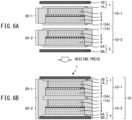
- FIG. 6A and FIG. 6B are views for explaining one example of the process of production the thin type stacked battery 100 of the second embodiment.
- the negative electrode material is made to disperse and is coated on release paper RP1 whereby the negative electrode 4 with the release paper RP1 attached is prepared.
- butyl lactate As the solvent, one other than butyl lactate may be used, but heptane, butyl lactate, etc. which are resistant to reacting with the SE are preferable.
- the positive electrode material is made to disperse and is coated on release paper RP3 (see FIG. 4D ) whereby the positive electrode 2 (see FIG. 4D ) with the release paper RP3 attached is prepared.
- separator material is made to disperse and is coated on release paper RP2 (see FIG. 4B ) whereby the separator 3 (see FIG. 4B ) with the release paper RP2 attached is prepared.
- the positive electrode 2 with the release paper RP3 attached is cut out (see FIG. 4D ). Further, as shown in FIG. 4B , the negative electrode 4 with the release paper RP1 attached is cut out and the separator 3 with the release paper RP2 attached is cut out.
- the shapes of the cut out positive electrode 2 with the release paper RP3 attached, the cut out negative electrode 4 with the release paper RP1 attached, and the cut out separator 3 with the release paper RP2 attached may be square, circular or polygonal.
- the positive electrode 2 is preferably smaller than the negative electrode 4.
- the negative electrode 4 and the separator 3 are made to face each other and are monoaxially pressed (for example, 392 MPa, 1 min).
- a pressure of 100 MPa or more is preferable.
- the release paper RP1 of the negative electrode 4 is removed and the release paper RP2 of the separator 3 is removed.
- the positive electrode 2 is made to face the separator 3 and is pressed by hydrostatic pressing (CIP: Cold Isostatic Pressing) (for example, 392 MPa, 1 min).
- CIP Cold Isostatic Pressing
- a pressing method other than the hydrostatic pressing may be used.
- the hydrostatic pressing is preferable from the viewpoint of suppressing short-circuits.
- the release paper RP3 of the positive electrode 2 is removed and an electrode (the positive electrode 2, the separator 3, and the negative electrode 4) is prepared.
- the resin layer 1A of) the positive electrode current collector 1, the seal material 20-1 (20-2), the electrode (the positive electrode 2, the separator 3, and the negative electrode 4), and (the resin layer 5A of) the negative electrode current collector 5 are stacked and the assembly is heated in a vacuum state (for example, 160°C and 1 min), whereby the unit cell 10-1 (10-2) is prepared.
- the external dimension of the seal material 20-1 (20-2) is preferably larger than the external dimension of (the resin layer 1A) of the positive electrode current collector 1 and the external dimension of (the resin layer 5A) of the negative electrode current collector 5.
- the heating is preferably performed in a vacuum state. The heating temperature depends on the seal material 20-1 (20-2). At the time of preparation of the prototype shown in the later explained FIG. 7A and
- FIG. 7B as the seal material 20-1 (20-2), a seal material (PP) made by Dai Nippon Printing Co., Ltd. was used.
- the unit cell 10-1 and the unit cell 10-2 are stacked and the aluminum foil functioning as the metal layer 1B of the positive electrode current collector 1 of the unit cell 10-1 and the copper foil or the nickel foil functioning as the metal layer 5B of the negative electrode current collector 5 of the unit cell 10-2 are arranged.
- the assembly is heated in the vacuum state (for example, 160°C for 1 min) whereby a stacked body (the thin type stacked battery 100 of the second embodiment) is prepared.
- FIG. 7A and FIG. 7B are photos of prototypes of the thin type stacked battery 100 of the second embodiment shown in FIG. 3 .
- FIG. 7A shows the thickness of the prototype of the thin type stacked battery 100 of the second embodiment
- FIG. 7B shows the voltage of the prototype of the thin type stacked battery 100 of the second embodiment.
- the thin type stacked battery 100 of the second embodiment as well, it is possible to simultaneously satisfy lighter weight, reduced thickness, and moisture permeation resistance.
- the thin type stacked battery of the present disclosure was explained with reference to the drawings, but the thin type stacked battery of the present disclosure is not limited to the above-mentioned embodiments and can be suitably changed within a range not deviating from the gist of the present disclosure.
- the constitutions of the examples of the above-mentioned embodiments may be suitably combined.
Landscapes
- Chemical & Material Sciences (AREA)
- Chemical Kinetics & Catalysis (AREA)
- Electrochemistry (AREA)
- General Chemical & Material Sciences (AREA)
- Engineering & Computer Science (AREA)
- Manufacturing & Machinery (AREA)
- Materials Engineering (AREA)
- Physics & Mathematics (AREA)
- Composite Materials (AREA)
- Condensed Matter Physics & Semiconductors (AREA)
- General Physics & Mathematics (AREA)
- Inorganic Chemistry (AREA)
- Secondary Cells (AREA)
- Dispersion Chemistry (AREA)
- Sealing Battery Cases Or Jackets (AREA)
- Cell Electrode Carriers And Collectors (AREA)
- Battery Electrode And Active Subsutance (AREA)
Abstract
A thin type stacked battery includes battery pack formed by a plurality of stacked unit cells, each formed by positive electrode current collector, positive electrode, electrolyte, negative electrode, and negative electrode current collector stacked in that order, and seal material. The positive electrode current collector of one unit cell, the negative electrode current collector of another unit cell, and the seal material function as an exterior body surrounding a surrounded part. At least one of the positive electrode current collector of one unit cell and the negative electrode current collector of the other unit cell has a metal layer. At least the negative electrode current collector of one unit cell and the positive electrode current collector of the other unit cell have resin layers.
Description
- The present disclosure relates to a thin type stacked battery.
- PTL 1 (
Japanese Unexamined Patent Publication No. 2020-061300 PLT 1, current collectors of the battery have conductive resin layers so as to lighten the weight of the battery. - If attempting to reduce the thickness in addition to lightening the weight of the battery, for example, a battery case (metal can case) such as described in
PTL 1 is liable to make reduction of the thickness of the battery difficult, so a caseless battery is desirable. If the battery described inPLT 1 is made caseless, moisture reaches the electrode bodies through current collectors having conductive resin layers and the battery performance is liable to deteriorate. - In consideration of the above-mentioned point, the present disclosure has as its object the provision of a thin type stacked battery able to simultaneously satisfy lighter weight, reduced thickness, and moisture permeation resistance.
- (1) One aspect of the present disclosure is a thin type stacked battery including: a battery pack formed by a plurality of stacked unit cells, each unit cell being formed by positive electrode current collector, positive electrode, electrolyte, negative electrode, and negative electrode current collector stacked in that order, and a seal material, wherein the positive electrode current collector of a first end unit cell which is the unit cell positioned at one end in the stacking direction among the plurality of stacked unit cells forming the battery pack, wherein the positive electrode current collector of the first end unit cell does not abut against the negative electrode current collector of the unit cell which adjoins the first end unit cell, the negative electrode current collector of a second end unit cell which is the unit cell positioned at the other end in the stacking direction among the plurality of stacked unit cells forming the battery pack, wherein the negative electrode current collector of the second end unit cell does not abut against the positive electrode current collector of the unit cell which adjoins the second end unit cell, and the seal material function as an exterior body surrounding a surrounded part which corresponds to the battery pack except the positive electrode current collector of the first end unit cell and the negative electrode current collector of the second end unit cell, at least one of the positive electrode current collector of the first end unit cell and the negative electrode current collector of the second end unit cell has a metal layer, and at least the negative electrode current collector of the first end unit cell and the positive electrode current collector of the second end unit cell have resin layers.
- (2) In the thin type stacked battery of the aspect (1), the electrolyte may be a solid electrolyte.
- (3) In the thin type stacked battery of the aspect (1), the negative electrode current collector of the first end unit cell, the positive electrode current collector of the second end unit cell, and the positive electrode current collectors and the negative electrode current collectors of the unit cells other than the first end unit cell and the second end unit cell among the plurality of stacked unit cells forming the battery pack may be embedded in the seal material.
- (4) In the thin type stacked battery according to the aspect (1), a thickness of each of the plurality of stacked unit cells may be 0.1 to 2 mm.
- (5) In the thin type stacked battery according to the aspect (1), an electrolyte may be included in at least one of the positive electrode and the negative electrode.
- (6) In the thin type stacked battery of the aspect (1), the metal layer of the positive electrode current collector of the first end unit cell may be larger than the positive electrode of the first end unit cell, and the metal layer of the negative electrode current collector of the second end unit cell may be larger than the negative electrode of the second end unit cell.
- (7) In the thin type stacked battery of the aspect (1), the metal layer of the positive electrode current collector of the first end unit cell and the seal material may be welded, and the metal layer of the negative electrode current collector of the second end unit cell and the seal material may be welded.
- (8) In the thin type stacked battery of the aspect (1), the seal material surrounding the positive electrode, the electrolyte, and the negative electrode of the first end unit cell and the seal material surrounding the positive electrode, the electrolyte, and the negative electrode of the unit cell adjoining the first end unit cell may be fused.
- (9) In the thin type stacked battery of the aspect (1), the battery pack may include the unit cell which is not either of the first end unit cell and the second end unit cell, and the positive electrode current collector and the negative electrode current collector of the unit cell which is not either of the first end unit cell and the second end unit cell may have resin layers.
- (10) In the thin type stacked battery of the aspect (1), the unit cell adjoining the first end unit cell may be the second end unit cell, and the unit cell adjoining the second end unit cell may be the first end unit cell.
- (11) In the thin type stacked battery of the aspect (1), one of the positive electrode current collector of the first end unit cell and the negative electrode current collector of the second end unit cell may be a current collector which does not have a metal layer, and the current collector which does not have the metal layer may have a resin layer.
- (12) In the thin type stacked battery of the aspect (1), the positive electrode current collector of the first end unit cell and the negative electrode current collector of the second end unit cell may have metal layers.
- (13) In the thin type stacked battery of the aspect (12), the positive electrode current collector of the first end unit cell may have a resin layer, and the negative electrode current collector of the second end unit cell may have a resin layer.
- (14) In the thin type stacked battery of the aspect (13), the resin layer of the positive electrode current collector of the first end unit cell may abut against the positive electrode of the first end unit cell, and the resin layer of the negative electrode current collector of the second end unit cell may abut against the negative electrode of the second end unit cell.
- (15) In the thin type stacked battery of the aspect (12), the positive electrode current collector of the first end unit cell having the metal layer may not have a resin layer, and the negative electrode current collector of the second end unit cell having the metal layer may not have a resin layer.
- (16) In the thin type stacked battery of the aspect (15), the metal layer of the positive electrode current collector of the first end unit cell may abut against the positive electrode of the first end unit cell, and the metal layer of the negative electrode current collector of the second end unit cell may abut against the negative electrode of the second end unit cell.
- (17) In the thin type stacked battery of the aspect (9), the resin layer of the negative electrode current collector of the first end unit cell may abut against the resin layer of the positive electrode current collector of the unit cell which is not either of the first end unit cell and the second end unit cell, and the resin layer of the negative electrode current collector of the unit cell which is not either of the first end unit cell and the second end unit cell may abut against the resin layer of the positive electrode current collector of the second end unit cell.
- According to the present disclosure, it is possible to simultaneously satisfy lighter weight, reduced thickness, and moisture permeation resistance of the thin type stacked battery.
-
-
FIG. 1 is a view schematically showing one example of a thin type stacked battery 100 of a first embodiment. -
FIG. 2 is a view schematically showing one example of part of a unit cell 10-1 (10-2, 10-3) included in the thin type stacked battery 100 of the first embodiment. -
FIG. 3 is a view schematically showing one example of the thin type stacked battery 100 of a second embodiment. -
FIG. 4A is a view for explaining one example of a process of production of part of the unit cell 10-1 (10-2) forming part of the thin type stacked battery 100 of the second embodiment. -
FIG. 4B is a view for explaining one example of a process of production of part of the unit cell 10-1 (10-2) forming part of the thin type stacked battery 100 of the second embodiment. -
FIG. 4C is a view for explaining one example of a process of production of part of the unit cell 10-1 (10-2) forming part of the thin type stacked battery 100 of the second embodiment. -
FIG. 4D is a view for explaining one example of a process of production of part of the unit cell 10-1 (10-2) forming part of the thin type stacked battery 100 of the second embodiment. -
FIG. 5A is a view for explaining one example of a process of production of part of the unit cell 10-1 (10-2) forming part of the thin type stacked battery 100 of the second embodiment. -
FIG. 5B is a view for explaining one example of a process of production of part of the unit cell 10-1 (10-2) forming part of the thin type stacked battery 100 of the second embodiment. -
FIG. 5C is a view for explaining one example of a process of production of part of the unit cell 10-1 (10-2) forming part of the thin type stacked battery 100 of the second embodiment. -
FIG. 6A is a view for explaining one example of a process of production of the thin type stacked battery 100 of the second embodiment. -
FIG. 6B is a view for explaining one example of a process of production of the thin type stacked battery 100 of the second embodiment. -
FIG. 7A shows a thickness of a prototype of the thin type stacked battery 100 of the second embodiment. -
FIG. 7B shows a voltage of the prototype of the thin type stacked battery 100 of the second embodiment. - Below, referring to the drawings, embodiments of a thin type stacked battery of the present disclosure will be explained.
-
FIG. 1 is a view schematically showing one example of the thin type stacked battery 100 of a first embodiment.FIG. 2 is a view schematically showing one example of part of a unit cell 10-1 (10-2, 10-3) forming part of abattery pack 10 forming part of the thin type stacked battery 100 of the first embodiment shown inFIG. 1 . - In the example shown in
FIG. 1 and FIG. 2 , the thin type stacked battery 100 is provided with thebattery pack 10 formed by the unit cell 10-1, the unit cell 10-2, and the unit cell 10-3 stacked together and with seal materials 20-1, 20-2, and 20-3. - The unit cell 10-1 is positioned at one end (end of top side of
FIG. 1 ) in the stacking direction (up-down direction ofFIG. 1 ) among the unit cells 10-1, 10-2, and 10-3 forming thebattery pack 10. The unit cell 10-1 is formed by positive electrodecurrent collector 1,positive electrode 2,separator 3 including an electrolyte (for example, theseparator 3 in which the electrolyte is impregnated),negative electrode 4, and negative electrodecurrent collector 5 stacked in that order from above inFIG. 1 and FIG. 2 . The positive electrodecurrent collector 1 of the unit cell 10-1 hasresin layer 1A andmetal layer 1B. - As the
resin layer 1A of the positive electrodecurrent collector 1 of the unit cell 10-1, it is possible to use any resin current collector functioning as the positiveelectrode current collector 1. That is, theresin layer 1A of the positive electrodecurrent collector 1 of the unit cell 10-1 is a conductive resin layer. Theresin layer 1A of the positive electrodecurrent collector 1 of the unit cell 10-1 is preferably a light weight current collector using a resin as its base. As theresin layer 1A of the positive electrodecurrent collector 1 of the unit cell 10-1, for example, a resin current collector (vinyl resin: VGCF® (vapor grown carbon fiber)=90:10 wt%) is used. - As the
metal layer 1B of the positive electrodecurrent collector 1 of the unit cell 10-1, it is possible to use any metal material through which moisture does not permeate. As themetal layer 1B of the positive electrodecurrent collector 1 of the unit cell 10-1, for example, aluminum foil can be used. - The
positive electrode 2 of the unit cell 10-1 abuts against theresin layer 1A of the positive electrodecurrent collector 1 of the unit cell 10-1. - As a positive electrode material forming the
positive electrode 2 of the unit cell 10-1, for example, LiNiCoMn, SE (solid electrolyte) (LiI-LiBr-Li2 S-P2 S5), VGCF (vapor grown carbon fiber), and SBR (styrene-butadiene rubber) mixed together can be used. Positive electrode active material, conductive assistant, and tackifier (binder) contained in thepositive electrode 2 of the unit cell 10-1 are not designated. - That is, the
positive electrode 2 of the unit cell 10-1 may contain the electrolyte. If thepositive electrode 2 of the unit cell 10-1 contains the electrolyte, the electrolyte is preferably the solid electrolyte with a high heat resistance (sulfide or oxide). This is because the solid electrolyte which is resistant to heat is necessary for heat welding of the seal material 20-1 etc. - As the positive electrode active material, for example, LiCoO2 , LiNiO2 , LiNia Cob O2 (a+b=1, 0<a<1, 0<b<1), LiMnO2, LiMn2 O4, LiNia Cob Mnc O2 (a+b+c=1, 0<a<1, 0<b<1, 0<c<1), LiFePO4, etc. can be used. Further, as the conductive assistant, for example, acetylene black (AB) etc. can be used. As the binder, for example, polyvinylidene fluoride (PVdF) etc. can be used.
- The electrolyte contained in the
separator 3 of the unit cell 10-1 is preferably the solid electrolyte with the high heat resistance due to the above-mentioned reasons. - As the material forming the
separator 3 of the unit cell 10-1, for example, the SE and the SBR mixed together may be used. - The
separator 3 of the unit cell 10-1 may be substantially formed by a solid electrolyte material. Theseparator 3 of the unit cell 10-1 may, for example, further contain the binder etc. Theseparator 3 of the unit cell 10-1 can contain any solid electrolyte material. Theseparator 3 of the unit cell 10-1 may, for example, contain an Li2 S-P2 S5 -based solid electrolyte etc. - As negative electrode material forming the
negative electrode 4 of the unit cell 10-1, for example, graphite, SE (LiI-LiBr-Li2 S-P2 S5 ), VGCF, and SBR mixed together can be used. Negative electrode active material, conductive assistant, and tackifier contained in thenegative electrode 4 of the unit cell 10-1 are not designated. - That is, the
negative electrode 4 of the unit cell 10-1 may contain the electrolyte. If thenegative electrode 4 of the unit cell 10-1 contains the electrolyte, due to the above-mentioned reasons, the electrolyte is preferably the solid electrolyte with the high heat resistance. - The negative electrode
current collector 5 of the unit cell 10-1 has aresin layer 5A and does not have ametal layer 5B. - The
resin layer 5A of the negative electrodecurrent collector 5 of the unit cell 10-1 abuts against thenegative electrode 4 of the unit cell 10-1. - As the
resin layer 5A of the negative electrodecurrent collector 5 of the unit cell 10-1, it is possible to use any resin current collector functioning as the negative electrodecurrent collector 5. That is, theresin layer 5A of the negative electrodecurrent collector 5 of the unit cell 10-1 is the conductive resin layer. Theresin layer 5A of the negative electrodecurrent collector 5 of the unit cell 10-1 is preferably the light weight current collector using the resin as its base. As theresin layer 5A of the negative electrodecurrent collector 5 of the unit cell 10-1, for example, the resin current collector (vinyl resin: VGCF (vapor grown carbon fiber)=90:10 wt%) is used. - The unit cell 10-2 is positioned at the other end (end of bottom side of
FIG. 1 ) in the stacking direction (up-down direction ofFIG. 1 ) among the three unit cells 10-1, 10-2, and 10-3 forming thebattery pack 10. The unit cell 10-2 is formed by the positive electrodecurrent collector 1, thepositive electrode 2, theseparator 3 including the electrolyte (for example, theseparator 3 in which the electrolyte is impregnated), thenegative electrode 4, and the negative electrodecurrent collector 5 stacked in that order from above inFIG. 1 and FIG. 2 . - The positive electrode
current collector 1 of the unit cell 10-2 has theresin layer 1A and does not have themetal layer 1B. Theresin layer 1A of the positive electrodecurrent collector 1 of the unit cell 10-2 is formed in the same way as theresin layer 1A of the positive electrodecurrent collector 1 of the unit cell 10-1. - The
positive electrode 2 of the unit cell 10-2 abuts against theresin layer 1A of the positive electrodecurrent collector 1 of the unit cell 10-2. Thepositive electrode 2 of the unit cell 10-2 is formed in the same way as thepositive electrode 2 of the unit cell 10-1. - The
separator 3 of the unit cell 10-2 is formed in the same way as theseparator 3 of the unit cell 10-1. - The
negative electrode 4 of the unit cell 10-2 is formed in the same way as thenegative electrode 4 of the unit cell 10-1. - The negative electrode
current collector 5 of the unit cell 10-2 has theresin layer 5A and themetal layer 5B. - The
resin layer 5A of the negative electrodecurrent collector 5 of the unit cell 10-2 abuts against thenegative electrode 4 of the unit cell 10-2. Theresin layer 5A of the negative electrodecurrent collector 5 of the unit cell 10-2 is formed in the same way as theresin layer 5A of the negative electrodecurrent collector 5 of the unit cell 10-1. - As the
metal layer 5B of the negative electrodecurrent collector 5 of the unit cell 10-2, it is possible to use any metal material through which moisture does not permeate. As themetal layer 5B of the negative electrodecurrent collector 5 of the unit cell 10-2, for example, copper foil or nickel foil can be used. - In the example shown in
FIG. 1 and FIG. 2 , the positive electrodecurrent collector 1 of the unit cell 10-1 has themetal layer 1B and the negative electrodecurrent collector 5 of the unit cell 10-2 has themetal layer 5B, but in another example, the positive electrodecurrent collector 1 of the unit cell 10-1 may have themetal layer 1B and the negative electrodecurrent collector 5 of the unit cell 10-2 may not have themetal layer 5B. That is, in this example, the negative electrodecurrent collector 5 of the unit cell 10-2 is a current collector which does not have themetal layer 5B, while the negative electrodecurrent collector 5 of the unit cell 10-2 not having themetal layer 5B has theresin layer 5A. - In still another example, the positive electrode
current collector 1 of the unit cell 10-1 may not have themetal layer 1B while the negative electrodecurrent collector 5 of the unit cell 10-2 may have themetal layer 5B. That is, in this example, the positive electrodecurrent collector 1 of the unit cell 10-1 is a current collector which does not have themetal layer 1B while the positive electrodecurrent collector 1 of the unit cell 10-1 not having themetal layer 1B has theresin layer 1A. - In the example shown in
FIG. 1 and FIG. 2 , the unit cell 10-3 is positioned in the middle of the stacking direction (up-down direction ofFIG. 1 ) among the three unit cells 10-1, 10-2, and 10-3 forming thebattery pack 10. That is, the unit cell 10-3 is arranged adjoining the unit cell 10-1 and adjoining the unit cell 10-2. The unit cell 10-3 is formed by the positive electrodecurrent collector 1, thepositive electrode 2, theseparator 3 including the electrolyte (for example, theseparator 3 in which the electrolyte is impregnated), thenegative electrode 4, and the negative electrodecurrent collector 5 stacked in that order from above inFIG. 1 and FIG. 2 . - The positive electrode
current collector 1 of the unit cell 10-3 has theresin layer 1A and does not have themetal layer 1B. Theresin layer 1A of the positive electrodecurrent collector 1 of the unit cell 10-3 abuts against theresin layer 5A of the negative electrodecurrent collector 5 of the unit cell 10-1. That is, theresin layer 5A of the negative electrodecurrent collector 5 of the unit cell 10-1 abuts against theresin layer 1A of the positive electrodecurrent collector 1 of the unit cell 10-3 which is neither the unit cell 10-1 nor the unit cell 10-2. Theresin layer 1A of the positive electrodecurrent collector 1 of the unit cell 10-3 is formed in the same way as theresin layer 1A of the positive electrodecurrent collector 1 of the unit cell 10-1. - The
positive electrode 2 of the unit cell 10-3 abuts against theresin layer 1A of the positive electrodecurrent collector 1 of the unit cell 10-3. Thepositive electrode 2 of the unit cell 10-3 is formed in the same way as thepositive electrode 2 of the unit cell 10-1. - The
separator 3 of the unit cell 10-3 is formed in the same way as theseparator 3 of the unit cell 10-1. - The
negative electrode 4 of the unit cell 10-3 is formed in the same way as thenegative electrode 4 of the unit cell 10-1. - The negative electrode
current collector 5 of the unit cell 10-3 has theresin layer 5A but does not have themetal layer 5B. Theresin layer 5A of the negative electrodecurrent collector 5 of the unit cell 10-3 abuts against thenegative electrode 4 of the unit cell 10-3. Further, theresin layer 5A of the negative electrodecurrent collector 5 of the unit cell 10-3 abuts against theresin layer 1A of the positive electrodecurrent collector 1 of the unit cell 10-2. That is, theresin layer 5A of the negative electrodecurrent collector 5 of the unit cell 10-3 which is neither the unit cell 10-1 nor the unit cell 10-2 abuts against theresin layer 1A of the positive electrodecurrent collector 1 of the unit cell 10-2. Theresin layer 5A of the negative electrodecurrent collector 5 of the unit cell 10-3 is formed in the same way as theresin layer 5A of the negative electrodecurrent collector 5 of the unit cell 10-1. - In the example shown in
FIG. 1 and FIG. 2 , a thickness of each of the unit cells 10-1, 10-2, and 10-3 is 0.1 to 2 mm. - In the example shown in
FIG. 1 and FIG. 2 , thebattery pack 10 is formed by stacking three unit cells 10-1, 10-2, and 10-3, but in other examples, thebattery pack 10 may be formed by stacking any number greater than or equal to 4 of unit cells 10-1, 10-2, 10-3, ... - In the example shown in
FIG. 1 and FIG. 2 , the seal material 20-1 has the function of sealing the unit cell 10-1. In more detail, the seal material 20-1 has the function of leaving only themetal layer 1B of the positive electrodecurrent collector 1 of the unit cell 10-1 exposed and covering and sealing the remaining parts of the unit cell 10-1. That is, the seal material 20-1 surrounds thepositive electrode 2, theseparator 3 including the electrolyte, and thenegative electrode 4 of the unit cell 10-1. As the seal material 20-1, it is possible to use any resin material having the function of covering and sealing the remaining parts of the unit cell 10-1. As the seal material 20-1, for example, PP (polypropylene) film can be used. - The seal material 20-2 has the function of sealing the unit cell 10-2. In more detail, the seal material 20-2 has the function of leaving only the
metal layer 5B of the negative electrodecurrent collector 5 of the unit cell 10-2 exposed and covering and sealing the remaining parts of the unit cell 10-2. That is, the seal material 20-2 surrounds thepositive electrode 2, theseparator 3 including the electrolyte, and thenegative electrode 4 of the unit cell 10-2. As the seal material 20-2, it is possible to use the resin material similar to the seal material 20-1. - The seal material 20-3 has the function of covering and sealing the unit cell 10-3. That is, the seal material 20-3 surrounds the
positive electrode 2, theseparator 3 including the electrolyte, and thenegative electrode 4 of the unit cell 10-3. Further, the seal material 20-3 and the seal material 20-1 are fused and the seal material 20-3 and the seal material 20-2 are fused. For this reason, the unit cells 10-1, 10-2, and 10-3 can be fixed by the seal materials 20-1, 20-2, and 20-3. Further, it is possible to keep down the liability of water invading thebattery pack 10 through the clearance between the seal material 20-1 and the seal material 20-3 and the liability of water invading thebattery pack 10 through the clearance between the seal material 20-2 and the seal material 20-3. As the seal material 20-3, it is possible to use the resin material similar to the seal material 20-1. - That is, the seal materials 20-1, 20-2, and 20-3 have the function of leaving the
metal layer 1B of the positive electrodecurrent collector 1 of the unit cell 10-1 and themetal layer 5B of the negative electrodecurrent collector 5 of the unit cell 10-2 exposed and covering and sealing the remaining parts of thebattery pack 10. - That is, in the example shown in
FIG. 1 and FIG. 2 , the positive electrodecurrent collector 1 of the unit cell 10-1, the negative electrodecurrent collector 5 of the unit cell 10-2, and the seal materials 20-1, 20-2, and 20-3 function as an exterior body surrounding a surrounded part which corresponds to thebattery pack 10 except the positive electrodecurrent collector 1 of the unit cell 10-1 and the negative electrodecurrent collector 5 of the unit cell 10-2. In other words, the negative electrodecurrent collector 5 of the unit cell 10-1, the positive electrodecurrent collector 1 of the unit cell 10-2, and the positive electrodecurrent collector 1 and negative electrodecurrent collector 5 of the unit cell 10-3 other than the unit cell 10-1 and unit cell 10-2 among the unit cells 10-1, 10-2, and 10-3 forming thebattery pack 10 are embedded in the seal materials 20-1, 20-2, and 20-3. For this reason, it is possible to suppress short circuit between the positive electrodecurrent collectors 1 and the negative electrodecurrent collectors 5 of the unit cells 10-1, 10-2, and 10-3. - Further, in the example shown in
FIG. 1 and FIG. 2 , as explained above, the positive electrodecurrent collector 1 of the unit cell 10-1 has themetal layer 1B and the negative electrodecurrent collector 5 of the unit cell 10-2 has themetal layer 5B. - Furthermore, in the example shown in
FIG. 1 and FIG. 2 , as explained above, the positive electrodecurrent collector 1 of the unit cell 10-1 has theresin layer 1A and the negative electrodecurrent collector 5 of the unit cell 10-1 has theresin layer 5A, the positive electrodecurrent collector 1 of the unit cell 10-2 has theresin layer 1A and the negative electrodecurrent collector 5 of the unit cell 10-2 has theresin layer 5A, and the positive electrodecurrent collector 1 of the unit cell 10-3 has theresin layer 1A and the negative electrodecurrent collector 5 of the unit cell 10-3 has theresin layer 5A. - In another example, the positive electrode
current collector 1 of the unit cell 10-1 having themetal layer 1B may not have theresin layer 1A and the negative electrodecurrent collector 5 of the unit cell 10-2 having themetal layer 5B may not have theresin layer 5A. In this example, themetal layer 1B of the positive electrodecurrent collector 1 of the unit cell 10-1 abuts against thepositive electrode 2 of the unit cell 10-1 and themetal layer 5B of the negative electrodecurrent collector 5 of the unit cell 10-2 abuts against thenegative electrode 4 of the unit cell 10-2. - In more detail, in the example shown in
FIG. 1 and FIG. 2 , (left-right direction dimension ofFIG. 1 of) themetal layer 1B of the positive electrodecurrent collector 1 of the unit cell 10-1 is larger than (left-right direction dimension ofFIG. 1 of) thepositive electrode 2 of the unit cell 10-1. Further, themetal layer 1B of the positive electrodecurrent collector 1 of the unit cell 10-1 and the seal material 20-1 are welded. For this reason, permeation of moisture to thepositive electrode 2 of the unit cell 10-1 can be suppressed by themetal layer 1B of the positive electrodecurrent collector 1 of the unit cell 10-2 and the seal material 20-1. - Furthermore, (left-right direction dimension of
FIG. 1 of) themetal layer 5B of the negative electrodecurrent collector 5 of the unit cell 10-2 is larger than (left-right direction dimension ofFIG. 1 of) thenegative electrode 4 of the unit cell 10-2. Further, themetal layer 5B of the negative electrodecurrent collector 5 of the unit cell 10-2 and the seal material 20-2 are welded. For this reason, permeation of moisture to thenegative electrode 4 of the unit cell 10-2 can be suppressed by themetal layer 5B of the negative electrodecurrent collector 5 of the unit cell 10-2 and the seal material 20-2. - In the thin type stacked battery 100 of the first embodiment, it is possible to simultaneously satisfy lighter weight, reduced thickness, and moisture permeation resistance.
- Below, a second embodiment of the thin type stacked battery of the present disclosure will be explained. The thin type stacked battery 100 of the second embodiment is formed in the same way as the above-mentioned thin type stacked battery 100 of the first embodiment except for the points explained below.
-
FIG. 3 is a view schematically showing one example of the thin type stacked battery 100 of the second embodiment. - In the example shown in
FIG. 3 , the thin type stacked battery 100 is provided with thebattery pack 10 formed by the unit cell 10-1 and the unit cell 10-2 stacked together and with the seal materials 20-1 and 20-2. - The unit cell 10-1 is positioned at one end (end of top side of
FIG. 3 ) in the stacking direction (up-down direction ofFIG. 3 ) among the two unit cells 10-1 and 10-2 forming thebattery pack 10. The unit cell 10-1 is formed in the same way as the unit cell 10-1 of the thin type stacked battery 100 of the first embodiment. - The unit cell 10-2 is positioned at the other end (end of bottom side of
FIG. 3 ) in the stacking direction (up-down direction ofFIG. 3 ) of the two unit cells 10-1 and 10-2 forming thebattery pack 10. The unit cell 10-2 is arranged adjoining the unit cell 10-1 and is formed in the same way as the unit cell 10-2 of the thin type stacked battery 100 of the first embodiment. - In the example shown in
FIG. 3 , unlike the example shown inFIG. 1 and FIG. 2 , theresin layer 1A of the positive electrodecurrent collector 1 of the unit cell 10-2 abuts against theresin layer 5A of the negative electrodecurrent collector 5 of the unit cell 10-1. - Further, in the example shown in
FIG. 3 , the seal material 20-1 and the seal material 20-2 are fused together and the unit cells 10-1, 10-2 are fixed by the seal materials 20-1 and 20-2. The seal materials 20-1 and 20-2 leave themetal layer 1B of the positive electrodecurrent collector 1 of the unit cell 10-1 and themetal layer 5B of the negative electrodecurrent collector 5 of the unit cell 10-2 exposed and cover and seal the remaining parts of thebattery pack 10. - In the example shown in
FIG. 3 , the positive electrodecurrent collector 1 of the unit cell 10-1, the negative electrodecurrent collector 5 of the unit cell 10-2, and the seal materials 20-1 and 20-2 function as the exterior body surrounding the surrounded part which corresponds to thebattery pack 10 except the positive electrodecurrent collector 1 of the unit cell 10-1 and the negative electrodecurrent collector 5 of the unit cell 10-2, and the negative electrodecurrent collector 5 of the unit cell 10-1 and the positive electrodecurrent collector 1 of the unit cell 10-2 are embedded in the seal materials 20-1 and 20-2. -
FIG. 4A to FIG. 4D andFIG. 5A to FIG. 5C are views for explaining one example of the process of production of part of the unit cell 10-1 (10-2) forming part of the thin type stacked battery 100 of the second embodiment.FIG. 6A and FIG. 6B are views for explaining one example of the process of production the thin type stacked battery 100 of the second embodiment. - In the example shown in
FIG. 4A to FIG. 6B , to produce the unit cell 10-1 (10-2), first, as shown inFIG. 4A , for example, using a solvent such as butyl lactate etc., the negative electrode material is made to disperse and is coated on release paper RP1 whereby thenegative electrode 4 with the release paper RP1 attached is prepared. - As the solvent, one other than butyl lactate may be used, but heptane, butyl lactate, etc. which are resistant to reacting with the SE are preferable.
- While not shown in
FIG. 4A , for example, using the solvent such as the butyl lactate etc., the positive electrode material is made to disperse and is coated on release paper RP3 (seeFIG. 4D ) whereby the positive electrode 2 (seeFIG. 4D ) with the release paper RP3 attached is prepared. Further, for example, using the solvent such as the butyl lactate etc., separator material is made to disperse and is coated on release paper RP2 (seeFIG. 4B ) whereby the separator 3 (seeFIG. 4B ) with the release paper RP2 attached is prepared. - Next, the
positive electrode 2 with the release paper RP3 attached is cut out (seeFIG. 4D ). Further, as shown inFIG. 4B , thenegative electrode 4 with the release paper RP1 attached is cut out and theseparator 3 with the release paper RP2 attached is cut out. The shapes of the cut outpositive electrode 2 with the release paper RP3 attached, the cut outnegative electrode 4 with the release paper RP1 attached, and the cut outseparator 3 with the release paper RP2 attached may be square, circular or polygonal. Thepositive electrode 2 is preferably smaller than thenegative electrode 4. - Next, as shown in
FIG. 4B and FIG. 4C , thenegative electrode 4 and theseparator 3 are made to face each other and are monoaxially pressed (for example, 392 MPa, 1 min). To raise the adhesion of the solid electrolyte, a pressure of 100 MPa or more is preferable. - Next, as shown in
FIG. 4C , the release paper RP1 of thenegative electrode 4 is removed and the release paper RP2 of theseparator 3 is removed. - Next, as shown in
FIG. 4C , thepositive electrode 2 is made to face theseparator 3 and is pressed by hydrostatic pressing (CIP: Cold Isostatic Pressing) (for example, 392 MPa, 1 min). A pressing method other than the hydrostatic pressing may be used. The hydrostatic pressing is preferable from the viewpoint of suppressing short-circuits. - Next, as shown in
FIG. 4D andFIG. 5A , the release paper RP3 of thepositive electrode 2 is removed and an electrode (thepositive electrode 2, theseparator 3, and the negative electrode 4) is prepared. - Next, as shown in
FIG. 5B and FIG. 5C , (theresin layer 1A of) the positive electrodecurrent collector 1, the seal material 20-1 (20-2), the electrode (thepositive electrode 2, theseparator 3, and the negative electrode 4), and (theresin layer 5A of) the negative electrodecurrent collector 5 are stacked and the assembly is heated in a vacuum state (for example, 160°C and 1 min), whereby the unit cell 10-1 (10-2) is prepared. The external dimension of the seal material 20-1 (20-2) is preferably larger than the external dimension of (theresin layer 1A) of the positive electrodecurrent collector 1 and the external dimension of (theresin layer 5A) of the negative electrodecurrent collector 5. From the viewpoint of the air seal, the heating is preferably performed in a vacuum state. The heating temperature depends on the seal material 20-1 (20-2). At the time of preparation of the prototype shown in the later explainedFIG. 7A and -
FIG. 7B , as the seal material 20-1 (20-2), a seal material (PP) made by Dai Nippon Printing Co., Ltd. was used. - Next, as shown in
FIG. 6A , the unit cell 10-1 and the unit cell 10-2 are stacked and the aluminum foil functioning as themetal layer 1B of the positive electrodecurrent collector 1 of the unit cell 10-1 and the copper foil or the nickel foil functioning as themetal layer 5B of the negative electrodecurrent collector 5 of the unit cell 10-2 are arranged. - Next, as shown in
FIG. 6A and FIG. 6B , the assembly is heated in the vacuum state (for example, 160°C for 1 min) whereby a stacked body (the thin type stacked battery 100 of the second embodiment) is prepared. -
FIG. 7A and FIG. 7B are photos of prototypes of the thin type stacked battery 100 of the second embodiment shown inFIG. 3 . In more detail,FIG. 7A shows the thickness of the prototype of the thin type stacked battery 100 of the second embodiment, whileFIG. 7B shows the voltage of the prototype of the thin type stacked battery 100 of the second embodiment. - In the thin type stacked battery 100 of the second embodiment as well, it is possible to simultaneously satisfy lighter weight, reduced thickness, and moisture permeation resistance.
- In this way, embodiments of the thin type stacked battery of the present disclosure were explained with reference to the drawings, but the thin type stacked battery of the present disclosure is not limited to the above-mentioned embodiments and can be suitably changed within a range not deviating from the gist of the present disclosure. The constitutions of the examples of the above-mentioned embodiments may be suitably combined.
Claims (17)
- A thin type stacked battery (100) comprising:a battery pack (10) formed by a plurality of stacked unit cells (10-1, 10-2, 10-3; 10-1, 10-2), each unit cell being formed by positive electrode current collector (1), positive electrode (2), electrolyte, negative electrode (4), and negative electrode current collector (5) stacked in that order, anda seal material (20-1, 20-2, 20-3; 20-1, 20-2), whereinthe positive electrode current collector (1) of a first end unit cell (10-1) which is the unit cell positioned at one end in the stacking direction among the plurality of stacked unit cells (10-1, 10-2, 10-3; 10-1, 10-2) forming the battery pack (10), wherein the positive electrode current collector (1) of the first end unit cell (10-1) does not abut against the negative electrode current collector (5) of the unit cell (10-3; 10-2) which adjoins the first end unit cell (10-1),the negative electrode current collector (5) of a second end unit cell (10-2) which is the unit cell positioned at the other end in the stacking direction among the plurality of stacked unit cells (10-1, 10-2, 10-3; 10-1, 10-2) forming the battery pack (10), wherein the negative electrode current collector (5) of the second end unit cell (10-2) does not abut against the positive electrode current collector (1) of the unit cell (10-3; 10-1) which adjoins the second end unit cell (10-2), andthe seal material (20-1, 20-2, 20-3; 20-1, 20-2)function as an exterior body surrounding a surrounded part which corresponds to the battery pack (10) except the positive electrode current collector (1) of the first end unit cell (10-1) and the negative electrode current collector (5) of the second end unit cell (10-2),at least one of the positive electrode current collector (1) of the first end unit cell (10-1) and the negative electrode current collector (5) of the second end unit cell (10-2) has a metal layer (1B, 5B), andat least the negative electrode current collector (5) of the first end unit cell (10-1) and the positive electrode current collector (1) of the second end unit cell (10-2) have resin layers (SA, 1A).
- The thin type stacked battery (100) according to claim 1, wherein the electrolyte is a solid electrolyte.
- The thin type stacked battery (100) according to claim 1, wherein the negative electrode current collector (5) of the first end unit cell (10-2), the positive electrode current collector (1) of the second end unit cell (10-2), and the positive electrode current collector (1) and the negative electrode current collector (5) of the unit cell (10-3) other than the first end unit cell (10-1) and the second end unit cell (10-2) among the plurality of stacked unit cells (10-1, 10-2, 10-3) forming the battery pack (10) are embedded in the seal material (20-1, 20-2, 20-3).
- The thin type stacked battery (100) according to claim 1, wherein a thickness of each of the plurality of stacked unit cells (10-1, 10-2, 10-3; 10-1, 10-2) is 0.1 to 2 mm.
- The thin type stacked battery (100) according to claim 1, wherein an electrolyte is included in at least one of the positive electrode and the negative electrode.
- The thin type stacked battery (100) according to claim 1, whereinthe metal layer (1B) of the positive electrode current collector (1) of the first end unit cell (10-1) is larger than the positive electrode (2) of the first end unit cell (10-1), andthe metal layer (5B) of the negative electrode current collector (5) of the second end unit cell (10-2) is larger than the negative electrode (4) of the second end unit cell (10-2).
- The thin type stacked battery (100) according to claim 1, whereinthe metal layer (1B) of the positive electrode current collector (1) of the first end unit cell (10-1) and the seal material (20-1) are welded, andthe metal layer (5B) of the negative electrode current collector (5) of the second end unit cell (10-2) and the seal material (20-2) are welded.
- The thin type stacked battery (100) according to claim 1, wherein the seal material (20-1) surrounding the positive electrode (2), the electrolyte, and the negative electrode (4) of the first end unit cell (10-1) and the seal material (20-3; 20-2) surrounding the positive electrode (2), the electrolyte, and the negative electrode (4) of the unit cell (10-3; 10-2) adjoining the first end unit cell (10-1) are fused.
- The thin type stacked battery (100) according to claim 1, whereinthe battery pack (10) includes the unit cell (10-3) which is not either of the first end unit cell (10-1) and the second end unit cell (10-2), andthe positive electrode current collector (1) and the negative electrode current collector (5) of the unit cell (10-3) which is not either of the first end unit cell (10-1) and the second end unit cell (10-2) have resin layers (1A, 5A).
- The thin type stacked battery (100) according to claim 1, whereinthe unit cell (10-2) adjoining the first end unit cell (10-1) is the second end unit cell (10-2), andthe unit cell (10-1) adjoining the second end unit cell (10-2) is the first end unit cell (10-1).
- The thin type stacked battery (100) according to claim 1, whereinone of the positive electrode current collector (1) of the first end unit cell (10-1) and the negative electrode current collector (5) of the second end unit cell (10-2) is a current collector which does not have a metal layer (1B; 5B), andthe current collector which does not have the metal layer has a resin layer (1A; 5A).
- The thin type stacked battery (100) according to claim 1, wherein the positive electrode current collector (1) of the first end unit cell (10-1) and the negative electrode current collector (5) of the second end unit cell (10-2) have metal layers (1B, 5B).
- The thin type stacked battery (100) according to claim 12, whereinthe positive electrode current collector (1) of the first end unit cell (10-1) has a resin layer (1A), andthe negative electrode current collector (5) of the second end unit cell (10-2) has a resin layer (5A).
- The thin type stacked battery (100) according to claim 13, whereinthe resin layer (1A) of the positive electrode current collector (1) of the first end unit cell (10-1) abuts against the positive electrode (2) of the first end unit cell (10-1), andthe resin layer (5A) of the negative electrode current collector (5) of the second end unit cell (10-2) abuts against the negative electrode (4) of the second end unit cell (10-2).
- The thin type stacked battery (100) according to claim 12, whereinthe positive electrode current collector (1) of the first end unit cell (10-1) having the metal layer (1B) does not have a resin layer (1A), andthe negative electrode current collector (5) of the second end unit cell (10-2) having the metal layer (5B) does not have a resin layer (5A).
- The thin type stacked battery (100) according to claim 15, whereinthe metal layer (1B) of the positive electrode current collector (1) of the first end unit cell (10-1) abuts against the positive electrode (2) of the first end unit cell (10-1), andthe metal layer (5B) of the negative electrode current collector (5) of the second end unit cell (10-2) abuts against the negative electrode (4) of the second end unit cell (10-2).
- The thin type stacked battery (100) according to claim 9, whereinthe resin layer (5A) of the negative electrode current collector (5) of the first end unit cell (10-1) abuts against the resin layer (1A) of the positive electrode current collector (1) of the unit cell (10-3) which is not either of the first end unit cell (10-1) and the second end unit cell (10-2), andthe resin layer (5A) of the negative electrode current collector (5) of the unit cell (10-3) which is not either of the first end unit cell (10-1) and the second end unit cell (10-2) abuts against the resin layer (1A) of the positive electrode current collector (1) of the second end unit cell (10-2).
Applications Claiming Priority (1)
| Application Number | Priority Date | Filing Date | Title |
|---|---|---|---|
| JP2023055290A JP7790387B2 (en) | 2023-03-30 | 2023-03-30 | Thin laminated battery |
Publications (1)
| Publication Number | Publication Date |
|---|---|
| EP4439737A1 true EP4439737A1 (en) | 2024-10-02 |
Family
ID=90361440
Family Applications (1)
| Application Number | Title | Priority Date | Filing Date |
|---|---|---|---|
| EP24161198.7A Pending EP4439737A1 (en) | 2023-03-30 | 2024-03-04 | Thin type stacked battery |
Country Status (5)
| Country | Link |
|---|---|
| US (1) | US20240332698A1 (en) |
| EP (1) | EP4439737A1 (en) |
| JP (1) | JP7790387B2 (en) |
| KR (1) | KR20240147547A (en) |
| CN (1) | CN118738713A (en) |
Citations (3)
| Publication number | Priority date | Publication date | Assignee | Title |
|---|---|---|---|---|
| JPS6081768A (en) * | 1983-10-07 | 1985-05-09 | Matsushita Electric Ind Co Ltd | Solid electrolyte secondary cell |
| JP2020061300A (en) | 2018-10-11 | 2020-04-16 | 日産自動車株式会社 | Current collector for non-aqueous electrolyte secondary battery |
| WO2022201837A1 (en) * | 2021-03-24 | 2022-09-29 | パナソニックIpマネジメント株式会社 | Battery |
Family Cites Families (2)
| Publication number | Priority date | Publication date | Assignee | Title |
|---|---|---|---|---|
| JP7209475B2 (en) | 2018-04-09 | 2023-01-20 | 日産自動車株式会社 | Battery manufacturing method |
| CN112840495B (en) | 2018-12-27 | 2024-10-29 | 松下知识产权经营株式会社 | Battery |
-
2023
- 2023-03-30 JP JP2023055290A patent/JP7790387B2/en active Active
-
2024
- 2024-02-29 US US18/591,180 patent/US20240332698A1/en active Pending
- 2024-03-04 EP EP24161198.7A patent/EP4439737A1/en active Pending
- 2024-03-26 CN CN202410348626.5A patent/CN118738713A/en active Pending
- 2024-03-26 KR KR1020240041318A patent/KR20240147547A/en active Pending
Patent Citations (4)
| Publication number | Priority date | Publication date | Assignee | Title |
|---|---|---|---|---|
| JPS6081768A (en) * | 1983-10-07 | 1985-05-09 | Matsushita Electric Ind Co Ltd | Solid electrolyte secondary cell |
| JP2020061300A (en) | 2018-10-11 | 2020-04-16 | 日産自動車株式会社 | Current collector for non-aqueous electrolyte secondary battery |
| WO2022201837A1 (en) * | 2021-03-24 | 2022-09-29 | パナソニックIpマネジメント株式会社 | Battery |
| US20240014519A1 (en) * | 2021-03-24 | 2024-01-11 | Panasonic Intellectual Property Management Co., Ltd. | Battery |
Also Published As
| Publication number | Publication date |
|---|---|
| US20240332698A1 (en) | 2024-10-03 |
| JP2024142900A (en) | 2024-10-11 |
| KR20240147547A (en) | 2024-10-08 |
| JP7790387B2 (en) | 2025-12-23 |
| CN118738713A (en) | 2024-10-01 |
Similar Documents
| Publication | Publication Date | Title |
|---|---|---|
| US11081682B2 (en) | Fabricating method of electrode assembly and electrochemical cell containing the same | |
| EP2772978B1 (en) | Electrode assembly and electrochemical device comprising same | |
| EP2555305A2 (en) | Electrode assembly having a novel structure and a production method for the same | |
| US11515568B2 (en) | Laminated battery and manufacturing method of laminated battery | |
| US12155034B2 (en) | Battery | |
| US20210296695A1 (en) | Battery | |
| US20200168874A1 (en) | Electrode assembly having improved heat stability | |
| US12401079B2 (en) | All-solid-state battery | |
| CN118843963A (en) | Battery assembly and all-solid-state battery comprising same | |
| EP4053953A1 (en) | Electrode assembly and method for manufacturing same | |
| EP4044331A1 (en) | Pouch-type secondary battery having increased energy density, and method for manufacturing same | |
| EP4439737A1 (en) | Thin type stacked battery | |
| KR20200090497A (en) | The Electrode And The Electrode Assembly | |
| JP5412898B2 (en) | Multilayer secondary battery | |
| KR20160140507A (en) | Electrode assembly with directional thickness and Lithium secondary battery comprising the same | |
| EP4428956B1 (en) | Stacked battery | |
| US20250309360A1 (en) | Method for producing laminated battery, laminated battery, and battery pack | |
| US20250343318A1 (en) | Battery | |
| US20250286247A1 (en) | Laminated battery and method for manufacturing laminated battery | |
| KR20250154659A (en) | Electrode current collector, its manufacturing method, and secondary battery electrode assembly including it | |
| KR20250137784A (en) | Electrode current collector, its manufacturing method, and secondary battery electrode assembly including it | |
| KR20250148058A (en) | Electrode current collector, its manufacturing method, and secondary battery electrode assembly including it | |
| KR20240087215A (en) | Electrode assembly, secondary battery comprising the same and method for manufacturing a electrode assembly | |
| KR20250148059A (en) | Electrode current collector, its manufacturing method, and secondary battery electrode assembly including it | |
| JP2025124376A (en) | stacked battery |
Legal Events
| Date | Code | Title | Description |
|---|---|---|---|
| PUAI | Public reference made under article 153(3) epc to a published international application that has entered the european phase |
Free format text: ORIGINAL CODE: 0009012 |
|
| STAA | Information on the status of an ep patent application or granted ep patent |
Free format text: STATUS: REQUEST FOR EXAMINATION WAS MADE |
|
| 17P | Request for examination filed |
Effective date: 20240321 |
|
| AK | Designated contracting states |
Kind code of ref document: A1 Designated state(s): AL AT BE BG CH CY CZ DE DK EE ES FI FR GB GR HR HU IE IS IT LI LT LU LV MC ME MK MT NL NO PL PT RO RS SE SI SK SM TR |