EP4439653A1 - Cooler for power module of inverter - Google Patents
Cooler for power module of inverter Download PDFInfo
- Publication number
- EP4439653A1 EP4439653A1 EP23206726.4A EP23206726A EP4439653A1 EP 4439653 A1 EP4439653 A1 EP 4439653A1 EP 23206726 A EP23206726 A EP 23206726A EP 4439653 A1 EP4439653 A1 EP 4439653A1
- Authority
- EP
- European Patent Office
- Prior art keywords
- flow path
- heat sink
- cooler
- groove part
- groove
- Prior art date
- Legal status (The legal status is an assumption and is not a legal conclusion. Google has not performed a legal analysis and makes no representation as to the accuracy of the status listed.)
- Granted
Links
Images


Classifications
-
- H—ELECTRICITY
- H05—ELECTRIC TECHNIQUES NOT OTHERWISE PROVIDED FOR
- H05K—PRINTED CIRCUITS; CASINGS OR CONSTRUCTIONAL DETAILS OF ELECTRIC APPARATUS; MANUFACTURE OF ASSEMBLAGES OF ELECTRICAL COMPONENTS
- H05K7/00—Constructional details common to different types of electric apparatus
- H05K7/20—Modifications to facilitate cooling, ventilating, or heating
- H05K7/2089—Modifications to facilitate cooling, ventilating, or heating for power electronics, e.g. for inverters for controlling motor
- H05K7/209—Heat transfer by conduction from internal heat source to heat radiating structure
-
- H—ELECTRICITY
- H05—ELECTRIC TECHNIQUES NOT OTHERWISE PROVIDED FOR
- H05K—PRINTED CIRCUITS; CASINGS OR CONSTRUCTIONAL DETAILS OF ELECTRIC APPARATUS; MANUFACTURE OF ASSEMBLAGES OF ELECTRICAL COMPONENTS
- H05K7/00—Constructional details common to different types of electric apparatus
- H05K7/20—Modifications to facilitate cooling, ventilating, or heating
- H05K7/2089—Modifications to facilitate cooling, ventilating, or heating for power electronics, e.g. for inverters for controlling motor
-
- H—ELECTRICITY
- H10—SEMICONDUCTOR DEVICES; ELECTRIC SOLID-STATE DEVICES NOT OTHERWISE PROVIDED FOR
- H10W—GENERIC PACKAGES, INTERCONNECTIONS, CONNECTORS OR OTHER CONSTRUCTIONAL DETAILS OF DEVICES COVERED BY CLASS H10
- H10W40/00—Arrangements for thermal protection or thermal control
- H10W40/40—Arrangements for thermal protection or thermal control involving heat exchange by flowing fluids
- H10W40/47—Arrangements for thermal protection or thermal control involving heat exchange by flowing fluids by flowing liquids, e.g. forced water cooling
-
- H—ELECTRICITY
- H02—GENERATION; CONVERSION OR DISTRIBUTION OF ELECTRIC POWER
- H02M—APPARATUS FOR CONVERSION BETWEEN AC AND AC, BETWEEN AC AND DC, OR BETWEEN DC AND DC, AND FOR USE WITH MAINS OR SIMILAR POWER SUPPLY SYSTEMS; CONVERSION OF DC OR AC INPUT POWER INTO SURGE OUTPUT POWER; CONTROL OR REGULATION THEREOF
- H02M7/00—Conversion of AC power input into DC power output; Conversion of DC power input into AC power output
- H02M7/003—Constructional details, e.g. physical layout, assembly, wiring or busbar connections
-
- H—ELECTRICITY
- H05—ELECTRIC TECHNIQUES NOT OTHERWISE PROVIDED FOR
- H05K—PRINTED CIRCUITS; CASINGS OR CONSTRUCTIONAL DETAILS OF ELECTRIC APPARATUS; MANUFACTURE OF ASSEMBLAGES OF ELECTRICAL COMPONENTS
- H05K7/00—Constructional details common to different types of electric apparatus
- H05K7/14—Mounting supporting structure in casing or on frame or rack
- H05K7/1422—Printed circuit boards receptacles, e.g. stacked structures, electronic circuit modules or box like frames
- H05K7/1427—Housings
- H05K7/1432—Housings specially adapted for power drive units or power converters
- H05K7/14322—Housings specially adapted for power drive units or power converters wherein the control and power circuits of a power converter are arranged within the same casing
-
- H—ELECTRICITY
- H05—ELECTRIC TECHNIQUES NOT OTHERWISE PROVIDED FOR
- H05K—PRINTED CIRCUITS; CASINGS OR CONSTRUCTIONAL DETAILS OF ELECTRIC APPARATUS; MANUFACTURE OF ASSEMBLAGES OF ELECTRICAL COMPONENTS
- H05K7/00—Constructional details common to different types of electric apparatus
- H05K7/20—Modifications to facilitate cooling, ventilating, or heating
- H05K7/20218—Modifications to facilitate cooling, ventilating, or heating using a liquid coolant without phase change in electronic enclosures
- H05K7/20245—Modifications to facilitate cooling, ventilating, or heating using a liquid coolant without phase change in electronic enclosures by natural convection; Thermosiphons
-
- H—ELECTRICITY
- H05—ELECTRIC TECHNIQUES NOT OTHERWISE PROVIDED FOR
- H05K—PRINTED CIRCUITS; CASINGS OR CONSTRUCTIONAL DETAILS OF ELECTRIC APPARATUS; MANUFACTURE OF ASSEMBLAGES OF ELECTRICAL COMPONENTS
- H05K7/00—Constructional details common to different types of electric apparatus
- H05K7/20—Modifications to facilitate cooling, ventilating, or heating
- H05K7/20218—Modifications to facilitate cooling, ventilating, or heating using a liquid coolant without phase change in electronic enclosures
- H05K7/20263—Heat dissipaters releasing heat from coolant
-
- H—ELECTRICITY
- H05—ELECTRIC TECHNIQUES NOT OTHERWISE PROVIDED FOR
- H05K—PRINTED CIRCUITS; CASINGS OR CONSTRUCTIONAL DETAILS OF ELECTRIC APPARATUS; MANUFACTURE OF ASSEMBLAGES OF ELECTRICAL COMPONENTS
- H05K7/00—Constructional details common to different types of electric apparatus
- H05K7/20—Modifications to facilitate cooling, ventilating, or heating
- H05K7/20218—Modifications to facilitate cooling, ventilating, or heating using a liquid coolant without phase change in electronic enclosures
- H05K7/20272—Accessories for moving fluid, for expanding fluid, for connecting fluid conduits, for distributing fluid, for removing gas or for preventing leakage, e.g. pumps, tanks or manifolds
-
- H—ELECTRICITY
- H05—ELECTRIC TECHNIQUES NOT OTHERWISE PROVIDED FOR
- H05K—PRINTED CIRCUITS; CASINGS OR CONSTRUCTIONAL DETAILS OF ELECTRIC APPARATUS; MANUFACTURE OF ASSEMBLAGES OF ELECTRICAL COMPONENTS
- H05K7/00—Constructional details common to different types of electric apparatus
- H05K7/20—Modifications to facilitate cooling, ventilating, or heating
- H05K7/2089—Modifications to facilitate cooling, ventilating, or heating for power electronics, e.g. for inverters for controlling motor
- H05K7/20927—Liquid coolant without phase change
-
- H—ELECTRICITY
- H10—SEMICONDUCTOR DEVICES; ELECTRIC SOLID-STATE DEVICES NOT OTHERWISE PROVIDED FOR
- H10W—GENERIC PACKAGES, INTERCONNECTIONS, CONNECTORS OR OTHER CONSTRUCTIONAL DETAILS OF DEVICES COVERED BY CLASS H10
- H10W40/00—Arrangements for thermal protection or thermal control
- H10W40/20—Arrangements for cooling
- H10W40/25—Arrangements for cooling characterised by their materials
-
- H—ELECTRICITY
- H10—SEMICONDUCTOR DEVICES; ELECTRIC SOLID-STATE DEVICES NOT OTHERWISE PROVIDED FOR
- H10W—GENERIC PACKAGES, INTERCONNECTIONS, CONNECTORS OR OTHER CONSTRUCTIONAL DETAILS OF DEVICES COVERED BY CLASS H10
- H10W90/00—Package configurations
Definitions
- the following disclosure relates to a cooler for a power module of an inverter, and more particularly, to a cooler for a power module of an inverter, which is configured to effectively cool a power module coupled to a heat sink.
- a vehicle is equipped with an inverter system as a power conversion device for converting high-voltage direct-current (DC) power generated from a battery or a fuel cell into alternating-current (AC) power of three phases (U-, V-, and W-phases).
- DC direct-current
- AC alternating-current
- Such an inverter system includes a power module, including a power conversion switching element (an insulated gate bipolar transistor (IGBT)), and a gate driving circuit.
- a power conversion switching element an insulated gate bipolar transistor (IGBT)
- IGBT insulated gate bipolar transistor
- a cooling structure such as a heat sink may be used to dissipate heat generated from the chip of the power module or the like.
- an existing power module cooling structure may employ a structure in which a pin is disposed on a base plate of a power module and the power module is watertight-treated and immersed in a housing with a flow path.
- a serial cooling structure for cooling power modules corresponding to the U-, V-, and W-phases of an inverter by causing a fluid, such as cooling water flowing in a flow path (hereinafter referred to as a fluid), to flow through the power modules in series or a parallel cooling structure for cooling power modules corresponding to U-, V-, and W-phases of an inverter by causing a fluid to flow through the power modules in parallel is employed.
- the serial cooling structure is configured to sequentially cool the power modules corresponding to the U-, V-, and W-phases of the inverter using a fluid and thus the power module at a rear end is less effectively cooled than the power module at a front end, thus increasing a temperature deviation between the power modules.
- the parallel cooling structure prevents an increase in a temperature deviation between the power modules but is configured to distribute a fluid to cause a relatively small amount of the fluid to flow through each of the power modules, thus reducing the cooling efficiency of each of the power modules.
- a cooler for a power module of an inverter including power modules comprising chips arranged in a row direction and a column direction perpendicular to the row direction, a heat sink extending in a first direction parallel to the row direction, the power modules being coupled to one surface of the heat sink and a microfluidic channel comprising grooves disposed on another surface of the heat sink, the grooves extending in a longitudinal direction of the heat sink, and a housing comprising a first groove part comprising an inlet configured to receive a fluid and a first groove extending in a second direction to communicate with the inlet, a second groove part comprising an outlet configured to discharge the fluid and a second groove extending in the second direction to communicate with the outlet, and a separation part formed between the first groove part and the second groove part, wherein the heat sink is coupled to the housing to cause the first direction to be parallel to the second direction, the first groove is covered with the heat sink to form a first flow path, the second groove part is covered with the heat sink to
- the longitudinal direction may be parallel to the column direction.
- a cross-sectional area of the flow path perpendicular to the longitudinal direction may be less than a cross-sectional area of the first flow path perpendicular to the second direction.
- the cross-sectional area of the flow path perpendicular to the longitudinal direction may be 0.1 times or more and 0.7 times or less of the cross-sectional area of the first flow path perpendicular to the second direction.
- a cross-sectional area of the second flow path perpendicular to the second direction may be greater than the cross-sectional area of the first flow path perpendicular to the second direction.
- a height of the first flow path in the vertical direction may increases in a direction from the first flow path to the second flow path, when the heat sink covers the first groove part, and a height of the second flow path in the vertical direction may decreases in the direction from the first flow path to the second flow path, when the heat sink covers the second first groove part.
- a chamfer may be provided on a corner of the separation part adjacent to the first groove part.
- the power modules may include three power modules corresponding to U-, V-, and W-phases of the inverter.
- a cooler for a heat generating device including a heat sink extending in a first direction, the heat generating device being coupled to one surface of the heat sink and a microfluidic channel comprising grooves disposed on another surface of the heat sink, the grooves extending in a longitudinal direction of the heat sink, and a housing comprising a first groove part comprising an inlet configured to receive a fluid and a first groove extending in a second direction to communicate with the inlet, a second groove part comprising an outlet configured to discharge the fluid and a second groove extending in the second direction to communicate with the outlet, and a separation part formed between the first groove part and the second groove part, wherein the heat sink is coupled to the housing to cause the first direction to be parallel to the second direction, the first groove is covered with the heat sink to form a first flow path, the second groove part is covered with the heat sink to form a second flow path, and the microfluidic channel covers the separation part to cause the grooves to form flow paths for communication of the first
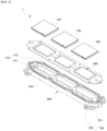
- FIG. 1 is an exploded perspective view of a cooler for a power module of an inverter according to an embodiment.
- a cooler 1 for a power module of an inverter includes a plurality of power modules 100, a heat sink 200, and a housing 300.
- the power module 100 is commonly referred to as a power semiconductor module, and may include an insulated gate bipolar transistor (IGBT), a MOSFET or bipolar transistor, or the like and be formed by disposing a direct-bonded copper (DBC) substrate on an upper surface of a base plate and attaching a chip to the DBC substrate.
- IGBT insulated gate bipolar transistor
- DBC direct-bonded copper
- the plurality of power modules 100 may be included in the cooler 1 for a power module of an inverter.
- the plurality of power modules 100 may be configured as three power modules 100 corresponding to the U-phase, V-phase, and W-phase of an inverter.
- FIG. 2 is a plan view of a power module.
- a power module 100 may include a plurality of chips 110 arranged in parallel in a row direction and a column direction perpendicular to the row direction.
- the heat sink 200 is a thermally conductive thin plate to which the power module 100 from which heat is to be dissipated may be coupled, and extends in a first direction.
- FIG. 3 is a plan view of one surface of a heat sink to which a power module is coupled.
- a plurality of power modules 100 are coupled to one surface of a heat sink 200 such that a row direction is parallel to a first direction.
- FIG. 4 is a bottom view of another surface of the heat sink in which a microfluidic channel is installed.
- FIG. 5 is an enlarged view of a region A of FIG. 4 .
- a microfluidic channel 210 may be installed on another surface of the heat sink 200.
- the microfluidic channel 210 may employ a configuration of a conventional microfluidic channel through which a fluid may flow. As shown in FIG. 5 , a plurality of fine grooves 211 extending in a longitudinal direction may be formed.
- the microfluidic channel 210 may be formed such that the longitudinal direction in which the fine grooves 211 are formed is parallel to the column direction in which the plurality of chips 110 are arranged.
- the microfluidic channel 210 covers a separation part 330, which will be described below, to form a fine flow path 360. At least one chip 110 among the plurality of chips 110 may be positioned in a vertical direction perpendicular to the row direction and the column direction from the fine flow path 360.
- the microfluidic channel 210 may be installed on the heat sink 200 such that the fine flow path 360 passes through a lower portion of the chips 110 included in the power module 100.
- the housing 300 may have a structure in which a fluid may flow therein, and includes a first groove part 310, a second groove part 320, and the separation part 330 as shown in FIG. 1 .
- the first groove part 310 includes an inlet 311 into which a fluid is introducible and a first groove 312 extending in a second direction to communicate with the inlet 311, and the second groove part 320 includes an outlet 321 through which the fluid is dischargeable and a second groove 322 extending in the second direction to communicate with the outlet 321.
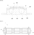
- FIG. 6 is a cross-sectional view of a cooler for a power module of an inverter, taken in a direction perpendicular to a second direction.
- the heat sink 200 when the heat sink 200 is coupled to the housing 300 such that the first direction is parallel to the second direction, the heat sink 200 is covered with the first groove part 310 to form a first flow path 340 and the heat sink 200 is covered with the second groove part 320 to form a second flow path 350.
- a cross-sectional area of the second flow path 350 perpendicular to the second direction may be formed to be larger than that of the first flow path 340 perpendicular to the second direction to reduce a pressure loss of the fluid flowing in the cooler 1 for a power module of an inverter.
- the separation part 330 may be formed between the first groove part 310 and the second groove part 320 to separate the first groove part 310 and the second groove part 320. As described above, when the heat sink 200 is coupled to the housing 300, the microfluidic channel 210 may cover the separation part 330 to form the fine flow path 360.
- a cross-sectional area of the fine flow path 360 perpendicular to the longitudinal direction may be formed to be smaller than that of the first flow path 340 perpendicular to the second direction, so that the fluid may flow quickly in the fine flow path 360 to effectively cool the plurality of power modules 100.
- the cross-sectional area of the fine flow path 360 perpendicular to the longitudinal direction may be set to be 0.1 times or more and 0.7 times or less of that of the first flow path 340 perpendicular to the second direction.
- the plurality of power modules 100 may be effectively cooled by the fluid flowing in the fine flow path 360.
- a chamfer may be formed at a corner C of the separation part 330 adjacent to the first groove part 310, and when the chamfer is formed on the separation part 330, the fluid may more easily flow through the first flow path 340, the fine flow path 360, and the second flow path 350, thereby reducing a pressure loss of the fluid flowing in the cooler 1 for a power module of an inverter.
- a vertical height of the first flow path 340 in a direction from the first flow path 340 to the second flow path 350 may gradually increase.
- a vertical height of the second flow path 350 in the direction from the first flow path 340 to the second flow path 350 may gradually decrease.
- an inclined corner portion B may be provided on the first flow path 340 and the second flow path 350.
- the fluid may more easily flow through the first flow path 340, the fine flow path 360, and the second flow path 350, thereby reducing a pressure loss of the fluid flowing in the cooler 1 for a power module of an inverter.
- FIG. 7 is a diagram illustrating a state in which a fluid flows in a cooler for a power module of an inverter.
- the fine flow path 360 is formed to have a smaller cross-sectional area than that of the first flow path 340 and to pass through a lower portion of the chip 110 generating a large amount of heat. Therefore, the fluid flowing in the fine flow path 360 flows at a high speed to effectively cool the power module 200.
- the fluid passing through the inside of the plurality of fine flow paths 360 flows into the second flow path 350 and thereafter is discharged to the outside of the cooler 1 for a power module of an inverter through the outlet 321 of the housing 300.
- the second flow path 350 is formed to have a larger cross-sectional area than that of the first flow path 340, the inclined corner portion B is formed on the first flow path 340 and the second flow path 350, and a chamfer is formed on the corner C of the separation part 330 adjacent to the first groove part 310, thereby reducing a pressure loss of the fluid flowing in the cooler 1 for a power module of an inverter.
- a cooler for a power module of an inverter is configured to cause a fluid to flow through power modules of an inverter in parallel to cool the power modules, thereby preventing an increase in a temperature deviation between the plurality of power modules.
- a fine flow path formed by a microfluidic channel is configured to be located in a lower portion of a chip that generates a large amount of heat and to have a relatively narrow cross-sectional area to allow the fluid to flow at a high speed, thereby achieving an effect of effectively cooling each of the power modules.
- a cross-sectional area of a second flow path is set to be larger than that of a first flow path, an inclined corner portion is provided on the first flow path and the second flow path, and a chamfer is provided on a corner of a separation part to minimize a pressure loss of a fluid flowing to cool a plurality of power modules, thereby reducing load on a device such as a water pump for injecting the fluid.
- a cooler for a power module of an inverter is configured to cause a fluid to flow through power modules of an inverter in parallel to cool the power modules of the inverter, thereby preventing an increase in a temperature deviation between the power modules.
- a fine flow path formed by a microfluidic channel is configured to be located in a lower portion of a chip that generates a large amount of heat and to have a relatively narrow cross-sectional area to allow the fluid to flow at a high speed, thereby achieving an effect of effectively cooling each of the power modules.
- a cross-sectional area of a second flow path is set to be larger than that of a first flow path, an inclined corner portion is provided on the first flow path and the second flow path, and a chamfer is provided on a corner of a separation part to minimize a pressure loss of a fluid flowing to cool a plurality of power modules, thereby reducing load on a device such as a water pump for injecting the fluid.
- a cooler for a power module of an inverter which is capable of preventing an increase in a temperature deviation between a plurality of power modules.
- a cooler for a power module of an inverter which is capable of effectively cooling each of a plurality of power modules when the plurality of power modules are cooled.
- a cooler for a power module of an inverter which is capable of minimizing a pressure loss of a fluid flowing to cool a plurality of power modules.
Landscapes
- Engineering & Computer Science (AREA)
- Microelectronics & Electronic Packaging (AREA)
- Physics & Mathematics (AREA)
- Thermal Sciences (AREA)
- Power Engineering (AREA)
- Cooling Or The Like Of Semiconductors Or Solid State Devices (AREA)
- Cooling Or The Like Of Electrical Apparatus (AREA)
- Inverter Devices (AREA)
Abstract
Description
- The following disclosure relates to a cooler for a power module of an inverter, and more particularly, to a cooler for a power module of an inverter, which is configured to effectively cool a power module coupled to a heat sink.
- In general, a vehicle is equipped with an inverter system as a power conversion device for converting high-voltage direct-current (DC) power generated from a battery or a fuel cell into alternating-current (AC) power of three phases (U-, V-, and W-phases).
- Such an inverter system includes a power module, including a power conversion switching element (an insulated gate bipolar transistor (IGBT)), and a gate driving circuit.
- When the inverter system operates, a large amount of heat is generated from a chip installed in a power module and emitting heat (hereinafter referred to as a chip) and thus a cooling structure such as a heat sink may be used to dissipate heat generated from the chip of the power module or the like.
- For example, an existing power module cooling structure may employ a structure in which a pin is disposed on a base plate of a power module and the power module is watertight-treated and immersed in a housing with a flow path.
- Specifically, either a serial cooling structure for cooling power modules corresponding to the U-, V-, and W-phases of an inverter by causing a fluid, such as cooling water flowing in a flow path (hereinafter referred to as a fluid), to flow through the power modules in series or a parallel cooling structure for cooling power modules corresponding to U-, V-, and W-phases of an inverter by causing a fluid to flow through the power modules in parallel is employed.
- However, the serial cooling structure is configured to sequentially cool the power modules corresponding to the U-, V-, and W-phases of the inverter using a fluid and thus the power module at a rear end is less effectively cooled than the power module at a front end, thus increasing a temperature deviation between the power modules.
- Meanwhile, the parallel cooling structure prevents an increase in a temperature deviation between the power modules but is configured to distribute a fluid to cause a relatively small amount of the fluid to flow through each of the power modules, thus reducing the cooling efficiency of each of the power modules.
- Therefore, it is necessary to develop a cooler, for a power module of an inverter, to prevent an increase in a temperature deviation between a plurality of power modules and increase the cooling efficiency of each of the power modules.
- This Summary is provided to introduce a selection of concepts in a simplified form that are further described below in the Detailed Description. This Summary is not intended to identify key features or essential features of the claimed subject matter, nor is it intended to be used as an aid in determining the scope of the claimed subject matter.
- In one general aspect, there is provided a cooler for a power module of an inverter, including power modules comprising chips arranged in a row direction and a column direction perpendicular to the row direction, a heat sink extending in a first direction parallel to the row direction, the power modules being coupled to one surface of the heat sink and a microfluidic channel comprising grooves disposed on another surface of the heat sink, the grooves extending in a longitudinal direction of the heat sink, and a housing comprising a first groove part comprising an inlet configured to receive a fluid and a first groove extending in a second direction to communicate with the inlet, a second groove part comprising an outlet configured to discharge the fluid and a second groove extending in the second direction to communicate with the outlet, and a separation part formed between the first groove part and the second groove part, wherein the heat sink is coupled to the housing to cause the first direction to be parallel to the second direction, the first groove is covered with the heat sink to form a first flow path, the second groove part is covered with the heat sink to form a second flow path, and the microfluidic channel covers the separation part to cause the grooves to form flow paths for communication of the first flow path and the second flow path, and wherein at least one of the chips is disposed in a vertical direction perpendicular to the row direction and the column direction from the flow path.
- The longitudinal direction may be parallel to the column direction.
- A cross-sectional area of the flow path perpendicular to the longitudinal direction may be less than a cross-sectional area of the first flow path perpendicular to the second direction.
- The cross-sectional area of the flow path perpendicular to the longitudinal direction may be 0.1 times or more and 0.7 times or less of the cross-sectional area of the first flow path perpendicular to the second direction.
- A cross-sectional area of the second flow path perpendicular to the second direction may be greater than the cross-sectional area of the first flow path perpendicular to the second direction.
- A height of the first flow path in the vertical direction may increases in a direction from the first flow path to the second flow path, when the heat sink covers the first groove part, and a height of the second flow path in the vertical direction may decreases in the direction from the first flow path to the second flow path, when the heat sink covers the second first groove part.
- A chamfer may be provided on a corner of the separation part adjacent to the first groove part.
- The power modules may include three power modules corresponding to U-, V-, and W-phases of the inverter.
- On another general aspect, there is provided a cooler for a heat generating device, including a heat sink extending in a first direction, the heat generating device being coupled to one surface of the heat sink and a microfluidic channel comprising grooves disposed on another surface of the heat sink, the grooves extending in a longitudinal direction of the heat sink, and a housing comprising a first groove part comprising an inlet configured to receive a fluid and a first groove extending in a second direction to communicate with the inlet, a second groove part comprising an outlet configured to discharge the fluid and a second groove extending in the second direction to communicate with the outlet, and a separation part formed between the first groove part and the second groove part, wherein the heat sink is coupled to the housing to cause the first direction to be parallel to the second direction, the first groove is covered with the heat sink to form a first flow path, the second groove part is covered with the heat sink to form a second flow path, and the microfluidic channel covers the separation part to cause the grooves to form flow paths for communication of the first flow path and the second flow path, and wherein at least one component of the heat generating device is disposed in a vertical direction perpendicular to the row direction and the column direction from the flow path.
- Other features and aspects will be apparent from the following detailed description, the drawings, and the claims.
-
-
FIG. 1 is an exploded perspective view of a cooler for a power module of an inverter according to an embodiment. -
FIG. 2 is a plan view of a power module. -
FIG. 3 is a plan view of one surface of a heat sink to which a power module is coupled; -
FIG. 4 is a bottom view of another surface of the heat sink in which a microfluidic channel is installed. -
FIG. 5 is an enlarged view of a region A ofFIG. 4 . -
FIG. 6 is a cross-sectional view of a cooler for a power module of an inverter, taken in a direction perpendicular to a second direction. -
FIG. 7 is a diagram illustrating a state in which a fluid flows in a cooler for a power module of an inverter. - Throughout the drawings and the detailed description, unless otherwise described or provided, the same drawing reference numerals will be understood to refer to the same elements, features, and structures. The drawings may not be to scale, and the relative size, proportions, and depiction of elements in the drawings may be exaggerated for clarity, illustration, and convenience.
- The following detailed description is provided to assist the reader in gaining a comprehensive understanding of the methods, apparatuses, and/or systems described herein. However, various changes, modifications, and equivalents of the methods, apparatuses, and/or systems described herein will be apparent after an understanding of the disclosure of this application. For example, the sequences of operations described herein are merely examples, and are not limited to those set forth herein, but may be changed as will be apparent after an understanding of the disclosure of this application, with the exception of operations necessarily occurring in a certain order. Also, descriptions of features that are known after an understanding of the disclosure of this application may be omitted for increased clarity and conciseness.
- The features described herein may be embodied in different forms and are not to be construed as being limited to the examples described herein. Rather, the examples described herein have been provided merely to illustrate some of the many possible ways of implementing the methods, apparatuses, and/or systems described herein that will be apparent after an understanding of the disclosure of this application.
- Throughout the specification, when an element is referred to as being "connected" to another element, it will be understood to include that the element is "directly connected" to the other element or is "electrically connected" to the other element with another element therebetween.
- Throughout the specification, when an element is referred to as being "on" another element, it should be understood that the element is in contact with the other element or another element is present therebetween.
- It will be understood that when an element is referred to as "including" another element, the element may further include other elements unless mentioned otherwise. In the specification, the terms such as "about" and "substantially" are used to indicate a corresponding numerical value or a value approximating thereto when a unique manufacturing or material allowable error is presented and to prevent accurate or absolute numerical values, which are presented to help the understanding of the present invention, from being unfairly used by unscrupulous infringers. As used throughout the specification of the present application, the term "operation to ..." or "operation of ..." should not be understood to mean "operation for..."
- Hereinafter, embodiments will be described in detail with reference to the accompanying drawings and the following description. The present invention is, however, not limited thereto and may be embodied in many different forms. Throughout the specification, the same reference numbers represent the same elements.
- Hereinafter, a configuration of a cooler for a power module of an inverter according to an embodiment of the present invention will be described.
-
FIG. 1 is an exploded perspective view of a cooler for a power module of an inverter according to an embodiment. - Referring to
FIG. 1 , acooler 1 for a power module of an inverter includes a plurality ofpower modules 100, aheat sink 200, and ahousing 300. - First, the
power module 100 will be described. - The
power module 100 is commonly referred to as a power semiconductor module, and may include an insulated gate bipolar transistor (IGBT), a MOSFET or bipolar transistor, or the like and be formed by disposing a direct-bonded copper (DBC) substrate on an upper surface of a base plate and attaching a chip to the DBC substrate. - The plurality of
power modules 100 may be included in thecooler 1 for a power module of an inverter. For example, the plurality ofpower modules 100 may be configured as threepower modules 100 corresponding to the U-phase, V-phase, and W-phase of an inverter. -
FIG. 2 is a plan view of a power module. - Referring to
FIG. 2 , apower module 100 may include a plurality ofchips 110 arranged in parallel in a row direction and a column direction perpendicular to the row direction. - As described above, when an inverter system operates, high heat is generated from the
chips 110 and thepower module 100 may be effectively cooled by dissipating the heat generated from thechips 110. - Next, the
heat sink 200 will be described. - The
heat sink 200 is a thermally conductive thin plate to which thepower module 100 from which heat is to be dissipated may be coupled, and extends in a first direction. -
FIG. 3 is a plan view of one surface of a heat sink to which a power module is coupled. - As shown in
FIG. 3 , a plurality ofpower modules 100 are coupled to one surface of aheat sink 200 such that a row direction is parallel to a first direction. -
FIG. 4 is a bottom view of another surface of the heat sink in which a microfluidic channel is installed.FIG. 5 is an enlarged view of a region A ofFIG. 4 . - As shown in
FIG. 4 , amicrofluidic channel 210 may be installed on another surface of theheat sink 200. - The
microfluidic channel 210 may employ a configuration of a conventional microfluidic channel through which a fluid may flow. As shown inFIG. 5 , a plurality offine grooves 211 extending in a longitudinal direction may be formed. - In this case, the
microfluidic channel 210 may be formed such that the longitudinal direction in which thefine grooves 211 are formed is parallel to the column direction in which the plurality ofchips 110 are arranged. - The
microfluidic channel 210 covers aseparation part 330, which will be described below, to form afine flow path 360. At least onechip 110 among the plurality ofchips 110 may be positioned in a vertical direction perpendicular to the row direction and the column direction from thefine flow path 360. - That is, the
microfluidic channel 210 may be installed on theheat sink 200 such that thefine flow path 360 passes through a lower portion of thechips 110 included in thepower module 100. - Next, the
housing 300 will be described. - The
housing 300 may have a structure in which a fluid may flow therein, and includes afirst groove part 310, asecond groove part 320, and theseparation part 330 as shown inFIG. 1 . - The
first groove part 310 includes aninlet 311 into which a fluid is introducible and afirst groove 312 extending in a second direction to communicate with theinlet 311, and thesecond groove part 320 includes anoutlet 321 through which the fluid is dischargeable and asecond groove 322 extending in the second direction to communicate with theoutlet 321. -
FIG. 6 is a cross-sectional view of a cooler for a power module of an inverter, taken in a direction perpendicular to a second direction. - As shown in
FIG. 6 , when theheat sink 200 is coupled to thehousing 300 such that the first direction is parallel to the second direction, theheat sink 200 is covered with thefirst groove part 310 to form afirst flow path 340 and theheat sink 200 is covered with thesecond groove part 320 to form asecond flow path 350. - Here, a cross-sectional area of the
second flow path 350 perpendicular to the second direction may be formed to be larger than that of thefirst flow path 340 perpendicular to the second direction to reduce a pressure loss of the fluid flowing in the cooler 1 for a power module of an inverter. - The
separation part 330 may be formed between thefirst groove part 310 and thesecond groove part 320 to separate thefirst groove part 310 and thesecond groove part 320. As described above, when theheat sink 200 is coupled to thehousing 300, themicrofluidic channel 210 may cover theseparation part 330 to form thefine flow path 360. - Here, a cross-sectional area of the
fine flow path 360 perpendicular to the longitudinal direction may be formed to be smaller than that of thefirst flow path 340 perpendicular to the second direction, so that the fluid may flow quickly in thefine flow path 360 to effectively cool the plurality ofpower modules 100. - Specifically, the cross-sectional area of the
fine flow path 360 perpendicular to the longitudinal direction may be set to be 0.1 times or more and 0.7 times or less of that of thefirst flow path 340 perpendicular to the second direction. In this case, the plurality ofpower modules 100 may be effectively cooled by the fluid flowing in thefine flow path 360. - A chamfer may be formed at a corner C of the
separation part 330 adjacent to thefirst groove part 310, and when the chamfer is formed on theseparation part 330, the fluid may more easily flow through thefirst flow path 340, thefine flow path 360, and thesecond flow path 350, thereby reducing a pressure loss of the fluid flowing in the cooler 1 for a power module of an inverter. - Meanwhile, when the
heat sink 200 covers thefirst groove part 310, a vertical height of thefirst flow path 340 in a direction from thefirst flow path 340 to thesecond flow path 350 may gradually increase. - In addition, when the
heat sink 200 covers thesecond groove part 320, a vertical height of thesecond flow path 350 in the direction from thefirst flow path 340 to thesecond flow path 350 may gradually decrease. - That is, as shown in
FIG. 6 , when theheat sink 200 is coupled to thehousing 300, an inclined corner portion B may be provided on thefirst flow path 340 and thesecond flow path 350. - As described above, when the inclined corner portion B is provided on the
first flow path 340 and thesecond flow path 350, the fluid may more easily flow through thefirst flow path 340, thefine flow path 360, and thesecond flow path 350, thereby reducing a pressure loss of the fluid flowing in the cooler 1 for a power module of an inverter. - Hereinafter, operations and effects of a cooler for a power module of an inverter according to an embodiment will be described.
-
FIG. 7 is a diagram illustrating a state in which a fluid flows in a cooler for a power module of an inverter. - Referring to
FIG. 7 , when a fluid such as cooling water flows into theinlet 311 of thehousing 300, the fluid flows in thefirst flow path 340 and thereafter flows into a plurality offine flow paths 360, thus dissipating heat generated from the plurality ofpower modules 100. - In this case, the
fine flow path 360 is formed to have a smaller cross-sectional area than that of thefirst flow path 340 and to pass through a lower portion of thechip 110 generating a large amount of heat. Therefore, the fluid flowing in thefine flow path 360 flows at a high speed to effectively cool thepower module 200. - The fluid passing through the inside of the plurality of
fine flow paths 360 flows into thesecond flow path 350 and thereafter is discharged to the outside of thecooler 1 for a power module of an inverter through theoutlet 321 of thehousing 300. - In the
cooler 1 for a power module of an inverter, thesecond flow path 350 is formed to have a larger cross-sectional area than that of thefirst flow path 340, the inclined corner portion B is formed on thefirst flow path 340 and thesecond flow path 350, and a chamfer is formed on the corner C of theseparation part 330 adjacent to thefirst groove part 310, thereby reducing a pressure loss of the fluid flowing in the cooler 1 for a power module of an inverter. - As described above, a cooler for a power module of an inverter according to an embodiment is configured to cause a fluid to flow through power modules of an inverter in parallel to cool the power modules, thereby preventing an increase in a temperature deviation between the plurality of power modules.
- A fine flow path formed by a microfluidic channel is configured to be located in a lower portion of a chip that generates a large amount of heat and to have a relatively narrow cross-sectional area to allow the fluid to flow at a high speed, thereby achieving an effect of effectively cooling each of the power modules.
- In addition, a cross-sectional area of a second flow path is set to be larger than that of a first flow path, an inclined corner portion is provided on the first flow path and the second flow path, and a chamfer is provided on a corner of a separation part to minimize a pressure loss of a fluid flowing to cool a plurality of power modules, thereby reducing load on a device such as a water pump for injecting the fluid.
- According to an embodiment, a cooler for a power module of an inverter is configured to cause a fluid to flow through power modules of an inverter in parallel to cool the power modules of the inverter, thereby preventing an increase in a temperature deviation between the power modules.
- A fine flow path formed by a microfluidic channel is configured to be located in a lower portion of a chip that generates a large amount of heat and to have a relatively narrow cross-sectional area to allow the fluid to flow at a high speed, thereby achieving an effect of effectively cooling each of the power modules.
- In addition, a cross-sectional area of a second flow path is set to be larger than that of a first flow path, an inclined corner portion is provided on the first flow path and the second flow path, and a chamfer is provided on a corner of a separation part to minimize a pressure loss of a fluid flowing to cool a plurality of power modules, thereby reducing load on a device such as a water pump for injecting the fluid.
- As disclosed above, there is provided a cooler for a power module of an inverter, which is capable of preventing an increase in a temperature deviation between a plurality of power modules.
- As disclosed above, there is provided a cooler for a power module of an inverter, which is capable of effectively cooling each of a plurality of power modules when the plurality of power modules are cooled.
- As disclosed above, there is provided a cooler for a power module of an inverter, which is capable of minimizing a pressure loss of a fluid flowing to cool a plurality of power modules.
- The above description of the present invention is intended to provide examples, and it will be understood by those of ordinary skill in the art that modifications may be easily made without departing from the technical idea or essential features of the present invention. Therefore, it should be understood that the embodiments of the present invention described above are merely examples in all respects and not restrictive. For example, components each described as a single type may be implemented in a distributed manner, and components described as being distributed may be implemented in a combined form.
- While this disclosure includes specific examples, it will be apparent after an understanding of the disclosure of this application that various changes in form and details may be made in these examples without departing from the spirit and scope of the claims and their equivalents. The examples described herein are to be considered in a descriptive sense only, and not for purposes of limitation. Descriptions of features or aspects in each example are to be considered as being applicable to similar features or aspects in other examples. Suitable results may be achieved if the described techniques are performed in a different order, and/or if components in a described system, architecture, device, or circuit are combined in a different manner, and/or replaced or supplemented by other components or their equivalents..
- Therefore, the scope of the disclosure is defined not by the detailed description, but by the claims and their equivalents, and all variations within the scope of the claims and their equivalents are to be construed as being included in the disclosure.
-
- 1: cooler for power module of inverter
- 100: power module
- 110: chip
- 200: heat sink
- 210: microfluidic channel
- 211: fine groove
- 300: housing
- 310: first groove part
- 320: second groove part
- 330: separation part
- 340: first flow path
- 350: second flow part
- 360: fine flow path
Claims (10)
- A cooler for a power module of an inverter, comprising:power modules comprising chips arranged in a row direction and a column direction perpendicular to the row direction;a heat sink extending in a first direction parallel to the row direction, the power modules being coupled to one surface of the heat sink and a microfluidic channel comprising grooves disposed on another surface of the heat sink, the grooves extending in a longitudinal direction of the heat sink; anda housing comprising a first groove part comprising an inlet configured to receive a fluid and a first groove extending in a second direction to communicate with the inlet, a second groove part comprising an outlet configured to discharge the fluid and a second groove extending in the second direction to communicate with the outlet, and a separation part formed between the first groove part and the second groove part,wherein the heat sink is coupled to the housing to cause the first direction to be parallel to the second direction, the first groove is covered with the heat sink to form a first flow path, the second groove part is covered with the heat sink to form a second flow path, and the microfluidic channel covers the separation part to cause the grooves to form flow paths for communication of the first flow path and the second flow path, andwherein at least one of the chips is disposed in a vertical direction perpendicular to the row direction and the column direction from the flow path.
- The cooler of claim 1, wherein the longitudinal direction is parallel to the column direction.
- The cooler of claim 1 or 2, wherein a cross-sectional area of the flow path perpendicular to the longitudinal direction is less than a cross-sectional area of the first flow path perpendicular to the second direction.
- The cooler of claim 3, wherein the cross-sectional area of the flow path perpendicular to the longitudinal direction is 0.1 times or more and 0.7 times or less of the cross-sectional area of the first flow path perpendicular to the second direction.
- The cooler of claim 3 or 4, wherein a cross-sectional area of the second flow path perpendicular to the second direction is greater than the cross-sectional area of the first flow path perpendicular to the second direction.
- The cooler of claim 5, wherein a height of the first flow path in the vertical direction increases in a direction from the first flow path to the second flow path, when the heat sink covers the first groove part, and a height of the second flow path in the vertical direction decreases in the direction from the first flow path to the second flow path, when the heat sink covers the second first groove part.
- The cooler of claim 5 or 6, wherein a chamfer is provided on a corner of the separation part adjacent to the first groove part.
- The cooler of claim 6, wherein the power modules comprise three power modules corresponding to U-, V-, and W-phases of the inverter.
- The cooler of claim 7, wherein the power modules comprise three power modules corresponding to U-, V-, and W-phases of the inverter.
- A cooler for a heat generating device, comprising:a heat sink extending in a first direction, the heat generating device being coupled to one surface of the heat sink and a microfluidic channel comprising grooves disposed on another surface of the heat sink, the grooves extending in a longitudinal direction of the heat sink; anda housing comprising a first groove part comprising an inlet configured to receive a fluid and a first groove extending in a second direction to communicate with the inlet, a second groove part comprising an outlet configured to discharge the fluid and a second groove extending in the second direction to communicate with the outlet, and a separation part formed between the first groove part and the second groove part,wherein the heat sink is coupled to the housing to cause the first direction to be parallel to the second direction, the first groove is covered with the heat sink to form a first flow path, the second groove part is covered with the heat sink to form a second flow path, and the microfluidic channel covers the separation part to cause the grooves to form flow paths for communication of the first flow path and the second flow path, andwherein at least one component of the heat generating device is disposed in a vertical direction perpendicular to the row direction and the column direction from the flow path.
Applications Claiming Priority (1)
| Application Number | Priority Date | Filing Date | Title |
|---|---|---|---|
| KR1020230040343A KR20240145637A (en) | 2023-03-28 | 2023-03-28 | Cooler for power module of inverter |
Publications (2)
| Publication Number | Publication Date |
|---|---|
| EP4439653A1 true EP4439653A1 (en) | 2024-10-02 |
| EP4439653B1 EP4439653B1 (en) | 2026-07-01 |
Family
ID=88600539
Family Applications (1)
| Application Number | Title | Priority Date | Filing Date |
|---|---|---|---|
| EP23206726.4A Active EP4439653B1 (en) | 2023-03-28 | 2023-10-30 | COOLER FOR POWER MODULE OF AN INVERTER |
Country Status (4)
| Country | Link |
|---|---|
| US (1) | US20240334660A1 (en) |
| EP (1) | EP4439653B1 (en) |
| KR (1) | KR20240145637A (en) |
| CN (1) | CN118741941A (en) |
Citations (2)
| Publication number | Priority date | Publication date | Assignee | Title |
|---|---|---|---|---|
| US20060108098A1 (en) * | 2004-11-24 | 2006-05-25 | General Electric Company | Heat sink with microchannel cooling for power devices |
| US20100226093A1 (en) * | 2009-03-09 | 2010-09-09 | General Electric Company | Methods for making millichannel substrate, and cooling device and apparatus using the substrate |
Family Cites Families (10)
| Publication number | Priority date | Publication date | Assignee | Title |
|---|---|---|---|---|
| US7564129B2 (en) * | 2007-03-30 | 2009-07-21 | Nichicon Corporation | Power semiconductor module, and power semiconductor device having the module mounted therein |
| US20100175857A1 (en) * | 2009-01-15 | 2010-07-15 | General Electric Company | Millichannel heat sink, and stack and apparatus using the same |
| US9980415B2 (en) * | 2015-08-20 | 2018-05-22 | Toyota Motor Engineering & Manufacturing North America, Inc. | Configurable double-sided modular jet impingement assemblies for electronics cooling |
| US9622380B1 (en) * | 2015-09-30 | 2017-04-11 | Toyota Motor Engineering & Manufacturing North America, Inc. | Two-phase jet impingement cooling devices and electronic device assemblies incorporating the same |
| US10822096B2 (en) * | 2018-03-30 | 2020-11-03 | Ge Aviation Systems Llc | Avionics cooling module |
| US10660242B2 (en) * | 2018-04-26 | 2020-05-19 | Chongqing Jinkang New Energy Vehicle Co., Ltd. | Electric vehicle inverter module heat sink |
| US11818831B2 (en) * | 2019-09-24 | 2023-11-14 | Borgwarner Inc. | Notched baffled heat exchanger for circuit boards |
| US11350545B2 (en) * | 2019-12-05 | 2022-05-31 | Ge Aviation Systems Llc | Cold plate assembly for an electronic component |
| US11071233B1 (en) * | 2020-03-10 | 2021-07-20 | Borgwarner, Inc. | Auxiliary-cooled electronics assembly with extruded cooling cavity |
| US11596088B2 (en) * | 2021-01-29 | 2023-02-28 | Toyota Motor Engineering & Manufacturing North America, Inc. | Asymmetric configurable double-sided manifold micro-channel cold plates |
-
2023
- 2023-03-28 KR KR1020230040343A patent/KR20240145637A/en active Pending
- 2023-10-30 US US18/497,334 patent/US20240334660A1/en active Pending
- 2023-10-30 EP EP23206726.4A patent/EP4439653B1/en active Active
- 2023-12-19 CN CN202311752343.9A patent/CN118741941A/en active Pending
Patent Citations (2)
| Publication number | Priority date | Publication date | Assignee | Title |
|---|---|---|---|---|
| US20060108098A1 (en) * | 2004-11-24 | 2006-05-25 | General Electric Company | Heat sink with microchannel cooling for power devices |
| US20100226093A1 (en) * | 2009-03-09 | 2010-09-09 | General Electric Company | Methods for making millichannel substrate, and cooling device and apparatus using the substrate |
Also Published As
| Publication number | Publication date |
|---|---|
| KR20240145637A (en) | 2024-10-07 |
| US20240334660A1 (en) | 2024-10-03 |
| CN118741941A (en) | 2024-10-01 |
| EP4439653B1 (en) | 2026-07-01 |
Similar Documents
| Publication | Publication Date | Title |
|---|---|---|
| US7755898B2 (en) | Semiconductor module and inverter device | |
| US7859103B2 (en) | Semiconductor module and inverter device | |
| US7760503B2 (en) | Semiconductor module and inverter device | |
| JP6315091B2 (en) | Cooler and fixing method of cooler | |
| US7551439B2 (en) | Fluid cooled electronic assembly | |
| EP2840604B1 (en) | Semiconductor device and cooler for semiconductor device | |
| JP7380062B2 (en) | semiconductor module | |
| US11984383B2 (en) | Semiconductor device | |
| CN107689368B (en) | Semiconductor device having switching element for suppressing potential variation | |
| KR20190133156A (en) | Semiconductor cooling array | |
| CN213692016U (en) | power semiconductor device | |
| JP2020092250A (en) | Semiconductor module, vehicle and manufacturing method | |
| CN113644038A (en) | Semiconductor Modules and Vehicles | |
| JP6922450B2 (en) | Semiconductor module | |
| JP6921282B1 (en) | Power converter | |
| US20240334660A1 (en) | Cooler for power module of inverter | |
| US12635515B2 (en) | Semiconductor power device, semiconductor power system and method for cooling a semiconductor power device | |
| US20230178455A1 (en) | Semiconductor device and power conversion device | |
| JP7856156B2 (en) | Coolers and semiconductor devices | |
| JP7233510B1 (en) | power converter | |
| US20250344356A1 (en) | Cooling System for a Power Module | |
| CN120977969A (en) | Direct liquid cooling of semiconductor devices |
Legal Events
| Date | Code | Title | Description |
|---|---|---|---|
| PUAI | Public reference made under article 153(3) epc to a published international application that has entered the european phase |
Free format text: ORIGINAL CODE: 0009012 |
|
| STAA | Information on the status of an ep patent application or granted ep patent |
Free format text: STATUS: THE APPLICATION HAS BEEN PUBLISHED |
|
| AK | Designated contracting states |
Kind code of ref document: A1 Designated state(s): AL AT BE BG CH CY CZ DE DK EE ES FI FR GB GR HR HU IE IS IT LI LT LU LV MC ME MK MT NL NO PL PT RO RS SE SI SK SM TR |
|
| STAA | Information on the status of an ep patent application or granted ep patent |
Free format text: STATUS: REQUEST FOR EXAMINATION WAS MADE |
|
| 17P | Request for examination filed |
Effective date: 20250401 |
|
| STAA | Information on the status of an ep patent application or granted ep patent |
Free format text: STATUS: EXAMINATION IS IN PROGRESS |
|
| 17Q | First examination report despatched |
Effective date: 20250714 |
|
| REG | Reference to a national code |
Ref country code: DE Ref legal event code: R079 Free format text: PREVIOUS MAIN CLASS: H01L0023373000 Ipc: H10W0040250000 Ref country code: DE Ref legal event code: R079 Ref document number: 602023019145 Country of ref document: DE Free format text: PREVIOUS MAIN CLASS: H01L0023373000 Ipc: H10W0040250000 |
|
| GRAP | Despatch of communication of intention to grant a patent |
Free format text: ORIGINAL CODE: EPIDOSNIGR1 |
|
| STAA | Information on the status of an ep patent application or granted ep patent |
Free format text: STATUS: GRANT OF PATENT IS INTENDED |
|
| RIC1 | Information provided on ipc code assigned before grant |
Ipc: H10W 40/25 20260101AFI20260112BHEP Ipc: H10W 40/47 20260101ALI20260112BHEP Ipc: H10W 90/00 20260101ALI20260112BHEP Ipc: H02M 7/00 20060101ALI20260112BHEP |
|
| INTG | Intention to grant announced |
Effective date: 20260129 |
|
| GRAS | Grant fee paid |
Free format text: ORIGINAL CODE: EPIDOSNIGR3 |
|
| GRAA | (expected) grant |
Free format text: ORIGINAL CODE: 0009210 |
|
| STAA | Information on the status of an ep patent application or granted ep patent |
Free format text: STATUS: THE PATENT HAS BEEN GRANTED |
|
| P01 | Opt-out of the competence of the unified patent court (upc) registered |
Free format text: CASE NUMBER: UPC_APP_0014465_4439653/2026 Effective date: 20260504 |
|
| AK | Designated contracting states |
Kind code of ref document: B1 Designated state(s): AL AT BE BG CH CY CZ DE DK EE ES FI FR GB GR HR HU IE IS IT LI LT LU LV MC ME MK MT NL NO PL PT RO RS SE SI SK SM TR |
|
| REG | Reference to a national code |
Ref country code: CH Ref legal event code: F10 Free format text: ST27 STATUS EVENT CODE: U-0-0-F10-F00 (AS PROVIDED BY THE NATIONAL OFFICE) Effective date: 20260701 Ref country code: GB Ref legal event code: FG4D |
|
| REG | Reference to a national code |
Ref country code: DE Ref legal event code: R096 Ref document number: 602023019145 Country of ref document: DE |
|
| REG | Reference to a national code |
Ref country code: IE Ref legal event code: FG4D |