EP4439603A1 - Low voltage switch pole with a baffle arrangement - Google Patents
Low voltage switch pole with a baffle arrangement Download PDFInfo
- Publication number
- EP4439603A1 EP4439603A1 EP23164401.4A EP23164401A EP4439603A1 EP 4439603 A1 EP4439603 A1 EP 4439603A1 EP 23164401 A EP23164401 A EP 23164401A EP 4439603 A1 EP4439603 A1 EP 4439603A1
- Authority
- EP
- European Patent Office
- Prior art keywords
- support body
- insulating material
- contact assembly
- switch pole
- movable contact
- Prior art date
- Legal status (The legal status is an assumption and is not a legal conclusion. Google has not performed a legal analysis and makes no representation as to the accuracy of the status listed.)
- Pending
Links
- 239000011810 insulating material Substances 0.000 claims abstract description 79
- 230000007246 mechanism Effects 0.000 claims description 8
- 230000000295 complement effect Effects 0.000 claims description 6
- 230000004888 barrier function Effects 0.000 claims description 3
- 239000007789 gas Substances 0.000 description 14
- 239000012777 electrically insulating material Substances 0.000 description 4
- 239000012815 thermoplastic material Substances 0.000 description 4
- 238000009434 installation Methods 0.000 description 3
- 229920001187 thermosetting polymer Polymers 0.000 description 3
- 230000008033 biological extinction Effects 0.000 description 2
- 238000004891 communication Methods 0.000 description 2
- 239000004020 conductor Substances 0.000 description 2
- 238000004519 manufacturing process Methods 0.000 description 2
- 239000000463 material Substances 0.000 description 2
- 239000011087 paperboard Substances 0.000 description 2
- 238000010791 quenching Methods 0.000 description 2
- 238000000926 separation method Methods 0.000 description 2
- 230000007704 transition Effects 0.000 description 2
- 230000015572 biosynthetic process Effects 0.000 description 1
- 230000002860 competitive effect Effects 0.000 description 1
- 230000008878 coupling Effects 0.000 description 1
- 238000010168 coupling process Methods 0.000 description 1
- 238000005859 coupling reaction Methods 0.000 description 1
- 230000001419 dependent effect Effects 0.000 description 1
- 238000011161 development Methods 0.000 description 1
- 238000009826 distribution Methods 0.000 description 1
- 230000000694 effects Effects 0.000 description 1
- 238000010292 electrical insulation Methods 0.000 description 1
- 239000011152 fibreglass Substances 0.000 description 1
- 239000003365 glass fiber Substances 0.000 description 1
- 238000000034 method Methods 0.000 description 1
- 230000000116 mitigating effect Effects 0.000 description 1
- 238000012986 modification Methods 0.000 description 1
- 230000004048 modification Effects 0.000 description 1
- 239000004033 plastic Substances 0.000 description 1
- 230000008569 process Effects 0.000 description 1
- 230000000171 quenching effect Effects 0.000 description 1
- 238000000638 solvent extraction Methods 0.000 description 1
- 238000012360 testing method Methods 0.000 description 1
- 230000008646 thermal stress Effects 0.000 description 1
Images





Classifications
-
- H—ELECTRICITY
- H01—ELECTRIC ELEMENTS
- H01H—ELECTRIC SWITCHES; RELAYS; SELECTORS; EMERGENCY PROTECTIVE DEVICES
- H01H9/00—Details of switching devices, not covered by groups H01H1/00 - H01H7/00
- H01H9/30—Means for extinguishing or preventing arc between current-carrying parts
-
- H—ELECTRICITY
- H01—ELECTRIC ELEMENTS
- H01H—ELECTRIC SWITCHES; RELAYS; SELECTORS; EMERGENCY PROTECTIVE DEVICES
- H01H9/00—Details of switching devices, not covered by groups H01H1/00 - H01H7/00
- H01H9/30—Means for extinguishing or preventing arc between current-carrying parts
- H01H9/302—Means for extinguishing or preventing arc between current-carrying parts wherein arc-extinguishing gas is evolved from stationary parts
-
- H—ELECTRICITY
- H01—ELECTRIC ELEMENTS
- H01H—ELECTRIC SWITCHES; RELAYS; SELECTORS; EMERGENCY PROTECTIVE DEVICES
- H01H73/00—Protective overload circuit-breaking switches in which excess current opens the contacts by automatic release of mechanical energy stored by previous operation of a hand reset mechanism
- H01H73/02—Details
- H01H73/18—Means for extinguishing or suppressing arc
-
- H—ELECTRICITY
- H01—ELECTRIC ELEMENTS
- H01H—ELECTRIC SWITCHES; RELAYS; SELECTORS; EMERGENCY PROTECTIVE DEVICES
- H01H1/00—Contacts
- H01H1/12—Contacts characterised by the manner in which co-operating contacts engage
- H01H1/14—Contacts characterised by the manner in which co-operating contacts engage by abutting
- H01H1/22—Contacts characterised by the manner in which co-operating contacts engage by abutting with rigid pivoted member carrying the moving contact
- H01H1/221—Contacts characterised by the manner in which co-operating contacts engage by abutting with rigid pivoted member carrying the moving contact and a contact pressure spring acting between the pivoted member and a supporting member
- H01H1/226—Contacts characterised by the manner in which co-operating contacts engage by abutting with rigid pivoted member carrying the moving contact and a contact pressure spring acting between the pivoted member and a supporting member having a plurality of parallel contact bars
-
- H—ELECTRICITY
- H01—ELECTRIC ELEMENTS
- H01H—ELECTRIC SWITCHES; RELAYS; SELECTORS; EMERGENCY PROTECTIVE DEVICES
- H01H71/00—Details of the protective switches or relays covered by groups H01H73/00 - H01H83/00
- H01H71/02—Housings; Casings; Bases; Mountings
-
- H—ELECTRICITY
- H01—ELECTRIC ELEMENTS
- H01H—ELECTRIC SWITCHES; RELAYS; SELECTORS; EMERGENCY PROTECTIVE DEVICES
- H01H71/00—Details of the protective switches or relays covered by groups H01H73/00 - H01H83/00
- H01H71/02—Housings; Casings; Bases; Mountings
- H01H71/0207—Mounting or assembling the different parts of the circuit breaker
- H01H71/0235—Contacts and the arc extinguishing space inside individual separate cases, which are positioned inside the housing of the circuit breaker
-
- H—ELECTRICITY
- H01—ELECTRIC ELEMENTS
- H01H—ELECTRIC SWITCHES; RELAYS; SELECTORS; EMERGENCY PROTECTIVE DEVICES
- H01H71/00—Details of the protective switches or relays covered by groups H01H73/00 - H01H83/00
- H01H71/02—Housings; Casings; Bases; Mountings
- H01H71/0264—Mountings or coverplates for complete assembled circuit breakers, e.g. snap mounting in panel
- H01H71/0271—Mounting several complete assembled circuit breakers together
-
- H—ELECTRICITY
- H01—ELECTRIC ELEMENTS
- H01H—ELECTRIC SWITCHES; RELAYS; SELECTORS; EMERGENCY PROTECTIVE DEVICES
- H01H73/00—Protective overload circuit-breaking switches in which excess current opens the contacts by automatic release of mechanical energy stored by previous operation of a hand reset mechanism
- H01H73/02—Details
- H01H73/04—Contacts
-
- H—ELECTRICITY
- H01—ELECTRIC ELEMENTS
- H01H—ELECTRIC SWITCHES; RELAYS; SELECTORS; EMERGENCY PROTECTIVE DEVICES
- H01H9/00—Details of switching devices, not covered by groups H01H1/00 - H01H7/00
- H01H9/30—Means for extinguishing or preventing arc between current-carrying parts
- H01H9/34—Stationary parts for restricting or subdividing the arc, e.g. barrier plate
-
- H—ELECTRICITY
- H01—ELECTRIC ELEMENTS
- H01H—ELECTRIC SWITCHES; RELAYS; SELECTORS; EMERGENCY PROTECTIVE DEVICES
- H01H9/00—Details of switching devices, not covered by groups H01H1/00 - H01H7/00
- H01H9/30—Means for extinguishing or preventing arc between current-carrying parts
- H01H2009/305—Means for extinguishing or preventing arc between current-carrying parts including means for screening for arc gases as protection of mechanism against hot arc gases or for keeping arc gases in the arc chamber
-
- H—ELECTRICITY
- H01—ELECTRIC ELEMENTS
- H01H—ELECTRIC SWITCHES; RELAYS; SELECTORS; EMERGENCY PROTECTIVE DEVICES
- H01H9/00—Details of switching devices, not covered by groups H01H1/00 - H01H7/00
- H01H9/30—Means for extinguishing or preventing arc between current-carrying parts
- H01H9/38—Auxiliary contacts on to which the arc is transferred from the main contacts
Definitions
- the present invention relates to a switch pole for a switching device suitable for installation in low-voltage electrical systems.
- the invention likewise relates to a switching device comprising one or more of said switch poles.
- Low voltage switching devices such as for example circuit breakers, disconnectors, contactors, or the like, comprise one or more switch poles, each including one or more fixed contacts and movable contacts that can be coupled to and uncoupled from one another.
- These devices also comprise driving means mechanically coupled to the movable contacts to move these latter relative to the fixed contacts, so that these electric contacts can be mutually coupled or uncoupled to allow or prevent electric currents to flow along the switch poles.
- driving means comprise, for instance, suitable mechanisms terminating in a shaft operatively connected to said movable contacts.
- Such undesired arcing phenomena may occur between some conductive parts of the movable contact assembly (for example the connection braids between the movable contact and the corresponding pole terminal) and the connecting rod mechanically the movable contact assembly to the above-mentioned driving mechanisms.
- the main aim of the present invention is to provide a switch pole for low voltage switching devices, which allows overcoming or mitigating the above-mentioned shortcomings.
- the present invention is aimed at providing a switch pole, in which arcing phenomena between conductive parts outside the arc-extinguishing region of the switch pole are prevented or remarkably limited during opening manoeuvres of the switch pole.
- Another object of the present invention is to provide a switch pole, in which undesired leaks of hot gases out of the switch pole are avoided or remarkably reduced during opening manoeuvres of the switch pole.
- a further object of the present invention is to provide a switch pole that is reliable in operation and relatively easy and cheap to manufacture at industrial level.
- the switch pole for a low voltage switching device, according to the following claim 1 and the related dependent claims.
- the switch pole comprises an insulating casing, which defines an internal space including a contact region and an arc extinguishing region.
- the switch pole further comprises a fixed contact assembly and a movable contact assembly positioned in the contact region of the switch pole.
- the fixed contact assembly and the movable contact assembly include, respectively, one or more fixed contacts and one or more movable contacts, which can be mutually coupled or uncoupled.
- the one or more fixed contacts are arranged at a rear wall of the insulating casing.
- the movable contact assembly of the switch pole is reversibly movable between a first position, in which said movable contacts are coupled to said fixed contacts, and a second position, in which said movable contacts are spaced apart from said fixed contacts.
- the movable contact assembly comprises a support body configured to support said movable contacts.
- Said support body has a first side facing the front wall of said insulating casing, and a second side facing the rear wall of the insulating casing.
- the one or more movable contacts of the movable contact assembly are arranged at the second side of said support body.
- the movable contact assembly comprises a connecting rod fixed to said support body and mechanically couplable to a driving mechanism of said movable contact assembly outside said switch pole.
- Said connecting rod protrudes from the first side of said support body and sticks out of the insulating casing of the switch pole by passing through a front window of the front wall of the insulating casing.
- the switch pole further comprises an arc chamber positioned in the arc extinguishing region of the switch pole.
- the arc chamber comprises a plurality of arc-breaking elements, which are preferably formed by arc-breaking plates.
- the switch pole comprises a baffle arrangement including one or more sheets of insulating material mounted on the movable contact assembly at the first side of the support body of said movable contact assembly.
- Said one or more sheets of insulating material move together with the movable contact assembly and are interposed between the support body of the movable contact assembly and the front wall of the insulating casing of the switch pole.
- Said one or more sheets of insulating material form an insulating dielectric barrier between one or more conductive parts and the connecting rod of said movable contact assembly.
- Said one or more sheets of insulating material obstruct at least partially the front window of the insulating casing of the switch pole, at least when said movable contact assembly reaches said second position during an opening manoeuvre of said switching device.
- said one or more sheets of insulating material obstruct at least partially said front window, also before said movable contact assembly reaches said second position during an opening manoeuvre of said switching device.
- said baffle arrangement comprises one or more sheets of insulating material fixed to the support body of the movable contact assembly at the first side of said support body.
- said baffle arrangement comprises one or more sheets of insulating material mounted on said connecting rod at the first side of the support body of the movable contact assembly in such a way to be movable relative to said movable contact assembly.
- said baffle arrangement comprises a first sheet of insulating material fixed to the support body of the movable contact assembly at the first side of said support body.
- Said first sheet of insulating material has a first sheet portion covering a first side region of said support body, from which said connecting rod protrudes, and a second sheet portion covering a second side region of said support body, at which conductive parts of the movable contact assembly are arranged.
- said first sheet of insulating material has a shape complementary to a profile of said support body at the first side of said support body, namely at said first and second side regions.
- said baffle arrangement comprises a plurality of second sheets of insulating material mounted on the connecting rod of the movable contact assembly and a third sheet of insulating material fixed to said support body, at the first side of said support body.
- the second sheets of insulating material cover the first side region of said support body and are movable relative to said movable contact assembly.
- the second sheets of insulating material are stacked one on another along a direction parallel to the connecting rod of the movable contact assembly.
- the third sheet of insulating material cover the second side region of said support body.
- the second sheets of insulating material have a shape complementary to a profile of said support body at the first side region of said support body.
- the second sheets of insulating material have a free end partially overlapping said third sheet of insulating material in such a way to be interposed between said third sheet of insulating material and said connecting rod.
- the baffle arrangement allows conductive parts of the movable contact assembly (especially the connecting braids with the corresponding pole terminal) to be effectively insulated from the actuating rod of said movable contact assembly.
- the baffle arrangement makes it possible to effectively limit the escape of hot gases from the front window of insulating casing of the switch pole, thus forcing them to pass through the arc chamber. On one hand, this further reduces the probability of undesired arcs forming between the conductive parts of the movable contact assembly and the actuating rod. On the other hand, the development of arcs along the entire arc chamber is favored, which greatly promotes the extinction of the above-mentioned electric arcs.
- the present invention relates to a switch pole 1 for a low voltage switching device 100, e.g., a circuit breaker, a disconnector, a contactor, or the like.
- a low voltage switching device 100 e.g., a circuit breaker, a disconnector, a contactor, or the like.
- the switching device 100 is particularly adapted for use in AC low voltage electrical systems and it will be described with reference to these applications. However, in principle, it may be used also in electric systems of different type, e.g., in DC low voltage electrical systems.
- low voltage typically relates to operating voltages up to 1,5 kV AC and 2 kV DC.
- the switching device 100 comprises one or more switch poles 1, according to the invention.
- the switching device 100 is of the three-phase type and it comprises three switch poles. However, according to other embodiments of the invention (not shown), the switching device 100 may include a different number of switch poles depending on the number of electric phases of the electric circuit, in which it must be installed.
- Each switch pole 1 of the switching device 100 comprises an insulating casing 2, which preferably defines an internal volume including a contact region 3 and an arc extinguishing region 4.
- the contact region 3 is a portion of internal volume of the switch pole where the electric contacts of the switch pole are arranged and operate.
- the arc-extinguishing region 4 is a portion of internal volume of the switch pole where there are arranged arc-quenching means 41 designed to extinguish possible electric arcs arising between the electric contacts of the switch pole, during the opening manoeuvres of the switching device.
- the contact region 3 and the arc extinguishing region 4 of the switch pole are adjacent and in fluid-dynamic communication one with another.
- the arc extinguishing region 4 is positioned at un upper level with respect to the contact region 3, i.e., in proximal position relative to a top side of this latter.
- the insulating casing 2 of the switch pole is shaped as a contoured box with opposite first and second lateral walls 21, 22, opposite front and rear walls 23, 24 and opposite top and bottom walls 25, 26.
- the insulating casing 2 is preferably formed by first and second half shells coupled one to another.
- a first half shell comprises the first lateral wall 21, a portion of the front wall 23, a portion of the rear wall 24 and a portion of the bottom wall 26, while a second half shell comprises the second lateral wall 22, a portion of the front wall 23, a portion of the rear wall 24 and a portion of the bottom wall 26.
- the top wall 25 of the insulating casing 2 is fixed to a further insulating enclosure 43 of another component (the arc chamber 40) of the switch pole and it may be removably installed in the switch pole together with such a component ( figure 3 ).
- the insulating casing 2 of the switch pole may be arranged differently.
- the top wall of the insulating casing may be integral with other walls of the insulating casing, or it may be self-standing so as to be removably couplable with other walls of the insulating casing.
- the top wall 25 of the insulating casing 2 is provided with several through openings to allow the exit of hot gases from the internal space of the switch pole, namely from the arc extinguishing region 4, during an opening manoeuvre of the switching device.
- the insulating casing 2 comprises an insulating wall 5, which partially separates the contact region 3 from the arc extinguishing region 4.
- the insulating wall 5 defines an insulating boundary between the contact region 3 and the arc extinguishing region 4 at the front wall 23 of the insulating casing 2 while the contact region 3 and the arc extinguishing region 4 remain in direct fluid-dynamic communication at the rear wall 24 of the insulating casing 2.
- This solution greatly helps to confine the electric arcs in the arc-extinguishing region 4 of the switch pole during opening manoeuvres.
- the insulating casing 2 is made of an electrically insulating material, e.g., a thermosetting or thermoplastic material.
- the switch pole 1 comprises a first pole terminal 7 and a second pole terminal 8.
- the pole terminals 7, 8 are electrically coupled with corresponding line conductors of an electric line.
- Such line conductors are, in turn, electrically connected to an electric power source (e.g., an electric power feeding or generation system or a section of electric grid) and to an electric load (e.g., an electric system or apparatus or a section of electric grid).
- the pole terminals 7, 8 are positioned at the rear wall 24 of the insulating casing 2 of the switch pole.
- pole terminals 7, 8 may be realized according to solutions of known type and it will be described hereinafter only with reference to the aspects of interest of the invention, for the sake of brevity.
- the switch pole 1 comprises a fixed contact assembly 31 and a movable contact assembly 32, which are positioned in the contact region 3 of the switch pole.
- the fixed contact assembly 31 comprises one or more fixed contacts 311, which are electrically connected to the first pole terminal 7 of the switch pole.
- the fixed contacts 311 are positioned at the rear wall 24 of the insulating casing 2, advantageously in proximal position relative to the arc-extinguishing region 4 of the switch pole.
- the fixed contacts 311 are formed by suitable conductive plates.
- the fixed contact assembly 31 comprises a pair of fixed contacts 311 (conductive tips or plates).
- the fixed contact assembly 31 may include a different number of electric contacts.
- the fixed contact assembly 31 may be realized according to solutions of known type and it will be described hereinafter only with reference to the aspects of interest of the invention, for the sake of brevity.
- the movable contact assembly 32 comprises one or more movable contacts 321, which are electrically connected to the second pole terminal 8 of the switch pole.
- the movable contacts 321 are formed by suitable conductive fingers.
- the movable contacts 321 can be mutually coupled or uncoupled to the fixed contacts 311.
- the movable contact assembly 32 is reversibly movable about a rotation axis A ( figure 4 ).
- the rotation axis A of the movable contact assembly 32 is perpendicular to the observation plane of these figures. In practice, it is parallel to the front and rear walls 23, 24 and perpendicular to the lateral walls 21, 22 of the insulating casing 2.
- the movable contact assembly 32 is reversibly movable between a first position C ( figure 7 ), in which the movable contacts 321 are coupled to the fixed contacts 311, and second position O ( figure 9 ), in which the movable contacts 321 are distally spaced from the fixed contacts 311.
- the first position C of the movable contacts 321 of each switch pole corresponds to a closed condition of the switching device 100 (and of each switch pole), in which electric currents are allowed to flow along the electric poles
- the second position O of the movable contacts 321 of each electric pole corresponds to an open condition of the switching device 100 (and of each switch pole), in which electric currents along the electric poles are interrupted.
- a transition of the movable contacts 321 of each switch pole from the above-mentioned first position to the above-mentioned second position constitute an opening manoeuvre of the switching device 100 (and of each switch pole) whereas an opposite transition of the movable contacts 321 of each switch pole from the above-mentioned second position to the above-mentioned first position constitute a closing manoeuvre of the switching device 100 (and of each switch pole).
- the movable contact assembly 32 comprises a pair of movable contacts 321.
- the movable contact assembly 32 may include a different number of electric contacts.
- the movable contact assembly 32 comprises a support body 322, preferably made of electrically insulating material, e.g., a thermosetting material.
- the support body 322 is rotatably coupled to the insulating casing 2 of the switch pole and it can rotate about the rotation axis A to allow coupling or separation of the movable contacts 321 to or from the corresponding fixed contacts 311 of the fixed contact assembly 31.
- the support body 322 supports the movable contacts 321 and one or more electrical connections 324 between the second pole terminal 8 and the movable contacts 321.
- the electrical connections 324 are formed by flexible conductive braids.
- the movable contact assembly 32 comprises a connecting rod 323 (partially shown in the cited figures), which is fixed to the support body 322.
- the connecting rod 323 is mechanically coupled to a corresponding driving mechanism (not shown) located outside the switch pole.
- the connecting rod 323 protrudes from the support body 322 and it sticks out of the insulating casing 2 of the switch pole by passing through a front window 230 of the front wall 23 of the insulating casing 2.
- the support body 322 has a first side 322A facing the front wall 23 of the insulating casing and a second side 322B facing the rear wall 23 of said insulating casing ( figure 4 ).
- the support body 322 comprises, at the first side 322A, a first side region 3221, from which said connecting rod 323 protrudes towards the front window 230 of the insulating casing 2 and the outer environment, and a second side region 3222, at which the above-mentioned electrical connections 324 (and possibly other conductive parts 325) are arranged.
- first side region 3221 and the second side region 3222 of the support body 322 are arranged upwardly and downwardly relative the support body 322, i.e., in proximal position and in distal position relative to the arc-extinguishing region 4 of the switch pole.
- the movable contacts 321 of the switch pole are arranged at the second side 322B of the support body 322. Conveniently, they are arranged upwardly relative to the support body 322, i.e., in proximal position relative to the arc-extinguishing region 4 of the switch pole in such a way to face the corresponding fixed contacts 311.
- the movable contact assembly 32 may be realized according to solutions of known type and it will be described hereinafter only with reference to the aspects of interest of the invention, for the sake of brevity.
- the switch pole 1 comprises an arc chamber 40 positioned in the arc extinguishing region 4 of the switch pole, conveniently above the contact region 3.
- the arc chamber 40 preferably comprises a plurality of arc-breaking elements 41 designed to extinguish possible electric arcs raising between the electric contacts 311, 321 of the switch pole when these latter are separating during an opening manoeuvre of the switching device 100.
- the arc-breaking elements 41 of the arc chamber 40 are preferably formed by arc-breaking plates arranged in parallel one to another, preferably along reference planes parallel to the front and rear walls 23, 24 of the insulating casing 2.
- the arc-breaking plates 41 are advantageously arranged at subsequent positions between the front and rear walls 23, 24 of the insulating casing 2, at increasing distances from the rear wall 24.
- the arc chamber 40 is formed by a self-standing structure that can be removably installed in the corresponding switch pole.
- the arc chamber 40 preferably comprises an insulating enclosure 43 (made of an electrically insulating material, e.g., a thermosetting or thermoplastic material), which can be removably fixed to the insulating casing 2.
- the arc-breaking elements 41 are conveniently fixed to the insulating enclosure 43.
- the top wall 25 of the insulating casing 2 is fixed to the insulating casing 43 of the arc chamber 40. In this way, it can be installed or removed together with the arc chamber 40.
- the arc chamber 40 may be simply formed by a sub-portion of the arc extinguishing region 4 of the switch pole, in which the arc-breaking elements 41 are arranged, for example by fixing them to the top wall 25 of the insulating casing 2 through suitable supports.
- the arc chamber 40 may be realized according to solutions of known type and it will be described hereinafter only with reference to the aspects of interest of the invention, for the sake of brevity.
- the switch pole 1 comprises a baffle arrangement 50 including one or more sheets 51, 52, 53 of electrically insulating material, e.g., made of a plastic material, paperboard, glass fiber, and the like.
- the baffle arrangement 50 is configured to form an insulating dielectric barrier between one or more conductive parts 324, 325 of the movable contact assembly 32 and the connecting rod 323.
- the baffle arrangement can thus isolate electrically the conductive parts 324, 325 of the movable contact assembly 32 (especially the electrical connections 324) from the connecting rod 323. In this way, the probability that undesired electric arcs strike between the conductive parts 324, 325 and the connecting rod 323, during an opening manoeuvre of the switching device, is prevented or drastically limited.
- the baffle arrangement 50 is also configured to obstruct, at least partially, the front window 230 of the insulating casing 2 at least when the movable contact assembly 32 reaches the above-mentioned second position O, during an opening manoeuvre of the switching device.
- one or more sheets of insulating material 51, 52 obstruct the portions of the front window 230 surrounding the connecting rod 323.
- the baffle arrangement 50 can thus segregate the internal volume of the switch pole from the outside environment, at the front window 230, during an opening manoeuvre of the switching device.
- a more efficient confinement of hot gases within the arc-extinguishing region 4 favors the flow of hot gases through the arc chamber 40 towards the openings of the top wall 25 of the insulating casing.
- Electric arcs forming between the electric contacts 311, 321 under separation, during an opening manoeuvre of the switching device are thus forced more effectively to develop along the arc chamber 40 (thereby involving a number of arc-breaker plates 41), which circumstance greatly favors the extinction of said electric arcs.
- the baffle arrangement 50 is configured to obstruct, at least partially, the front window 230, also when the opening manoeuvre of the switching device is not completed yet, before the movable contact assembly 32 reaches the above-mentioned second position O.
- the baffle arrangement 50 comprises one or more sheets 51, 53 of insulating material fixed to the support body 322 at the first side 322A of this latter in such a way to form one piece with said movable contact assembly.
- These fixed sheets 51, 53 of insulating material move solidly (i.e., as one piece) with said movable contact assembly 32, when this latter moves during the manoeuvres of the switching device.
- the baffle arrangement 50 comprises one or more sheets 52 of insulating material mounted on the connecting rod 323 at the first side 322A of the support body 322 in such a way to be movable relative to the movable contact assembly 32.
- These movable sheets 52 of insulating material generally move together with the movable contact assembly 32 during the manoeuvres of the switching device. However, under certain circumstances, they can move relative to the movable contact assembly 32.
- these movable sheets 52 of insulating material are pushed towards the front window 230 of the insulating casing 2 by the pressure exerted by hot gases flowing towards the front window 230.
- the sheets 52 of insulating material thus slide along the connecting rod 323 and reach the front wall 23, while the movable contact assembly 32 is still moving. They can thus obstruct the front window 230 before the movable contact assembly 32 reaches the second position O.
- the baffle arrangement 50 may comprise the above-mentioned movable sheets 52 of insulating material in addition to one or more fixed sheets 53 of insulating material. According to other variants (not shown), however, the baffle arrangement 50 may comprise only the above-mentioned movable sheets 52 of insulating material.
- the one or more sheets 51, 52, 53 of insulating material are sandwiched between the first side 322A of the support body 322 and the front wall 23 of the insulating casing 2, when the movable contact assembly 32 reaches the second position O.
- the 51, 52, 53 of insulating material are structurally flexible to conform better to the profile of the front wall 23.
- FIG. 5 shows an embodiment of the invention, in which the baffle arrangement 50 comprises a single first sheet 51 of insulating material (e.g., a thermoplastic material) fixed on the support body 322 of the movable contact assembly.
- insulating material e.g., a thermoplastic material
- the first sheet of insulating material 51 has a shape complementary to the profile of the first side 322A of the support body 322 in such a way to follow the outer surface of this latter. In this way, the first sheet of insulating material 51 does not limit the rotation angle of the movable contact assembly 32 when it is sandwiched between said movable contact assembly and the front wall 23 of the insulating casing.
- the first sheet of insulating material 51 has a deformable structure to conform better to the profile of the front wall 23 when it is sandwiched between the movable contact assembly 32 and the front wall 23.
- the first sheet of insulating material 51 comprises a first sheet portion 511 covering the first side region 3221 of the support body 322 and fixed to this latter through suitable screws or equivalent mechanical connection means.
- the first sheet portion 511 comprises a hole 511A for the passage of the connecting rod 323, which protrudes from the support body 322.
- the first sheet portion 511 obstructs at least partially the front window 230 of the insulating casing 2, thereby segregating the internal volume of the switch pole from the outer environment at the front window 230.
- the first sheet portion 511 obstructs the portions of front widow 230, which surround the connecting rod 323 and which are left free by the connecting rod 323, when this latter passes through the front window 230.
- the first sheet of insulating material 51 additionally comprises a second sheet portion 512 covering the second side region 3222 of the support body 322, at which the electrical connections 324 are arranged.
- the second sheet portion 512 is fixed to the support body 322 through suitable screws or equivalent mechanical connection means.
- FIG. 6 shows another embodiment of the invention.
- the baffle arrangement 50 comprises a plurality of second sheets 52 of insulating material (e.g., made of paperboard or fiber glass) covering the first side region 3221 of the support body 322.
- the second sheets 52 of insulating material are mounted on the connecting rod 323 at the first side 322A of the support body 322 and are not fixed to the support body 322 so that they can move relative to the movable contact assembly 32 while they move together with this latter, particularly during an opening manoeuvre of the switching device.
- they are provided with a suitable hole or aperture 520, through which the connecting rod 323 is inserted. In this way, they can be easily stacked one on another along said connecting rod.
- the second sheets 52 of insulating material obstruct at least partially the front window 230 of the insulating casing 2, when the movable contact assembly 32 reaches the above-mentioned second position during an opening manoeuvre of the switching device.
- one or more second sheets 52 of insulating material are pushed towards the front window 230 of the insulating casing 2 by the incoming hot gases and obstruct at least partially the front window 230 also before the opening manoeuvre is completed.
- the second sheets 52 of insulating material have a shape complementary to the profile of the support body 322 at the first side region 3221 of said support body.
- the second sheets of insulating material 52 have a deformable structure to conform better to the profile of the front wall 23 when they are sandwiched between the movable contact assembly 32 and the front wall 23.
- the baffle arrangement 50 further comprises a third sheet 53 of insulating material (e.g. made of a thermoplastic material) fixed to the support body 322 at the first side 322A of said support body.
- a third sheet 53 of insulating material e.g. made of a thermoplastic material
- the third sheet 53 of insulating material covers the second side region 3222 of the support body 322 and it is interposed between the electrical connections 324 and the connected rod 324, thereby electrically insulating this latter from said electrical connections.
- the third sheet 53 of insulating material is fixed to the support body 322 through suitable screws or equivalent mechanical connection means.
- the third sheet of insulating material 53 has a deformable structure to conform better to the profile of the front wall 23 when it is sandwiched between the movable contact assembly 32 and the front wall 23.
- the second sheets 52 of insulating material have lower free ends 521 partially overlapping with the third sheet 53 of insulating material in such a way to be interposed between the third sheet 53 of insulating material and the connecting rid 323.
- connection elements 325 e.g., screws
- live parts e.g. one or more partitioning members of the electrical connections 324, which are fixed to the support body 322 - figures 4 and 7-8
- connection elements 325 may be used also for fixing the third sheet 53 of insulating material to the support body 322 without jeopardizing the electrical insulation of the connecting rod 323.
- Figures 7-9 show the behaviour of the switch pole 1, according to the embodiment of figure 6 , during an opening manoeuvre of the switching device 100.
- Figure 7 shows the switch pole with the movable contact assembly in the first position C.
- the movable contacts 321 are electrically and mechanically coupled to the fixed contacts 311. In this situation, a current can flow along the switch pole between the pole terminals 7, 8. No electric arcs develop between the above-mentioned electric contacts 311, 321.
- the movable contact assembly 32 rotates about the rotation axis A and the movable contacts 321 are moved away from the fixed contacts 311 ( figure 8 - dotted arrow).
- the movable contacts 321 As soon as the movable contacts 321 separate from the fixed contacts 311, a difference of voltage potential is established between said electric contacts (at any time, the movable contacts 321 may have a positive voltage polarity while the fixed contacts 311 may have a negative voltage polarity, or vice-versa). Since the dielectric distance between the electric contacts 311, 321 increases, electric arcs develop between said electric contacts. The high energy ionization effects of the dielectric medium (air) between the electric contacts 311, 321 leads to the generation of highpressure hot gases, a portion of which starts flowing towards the front window 230 of the insulating casing 2.
- the second sheets 52 of insulating Due to the pressure exerted by the hot gases, the second sheets 52 of insulating are pushed towards the front window 230.
- the second sheets 52 of insulating slide along the connecting rod 323, while the movable contact assembly 32 is moving, and obstruct the front window 230 before the movable contact assembly 32 ( figure 8 ).
- the hot gases cannot flow through the front window 230 and return towards the arc extinguishing region 4 of the switch pole.
- both the second and third sheets 52, 53 of insulating material electrically insulate the live parts 324, 325 of the movable contact assembly from the connecting rod 323.
- both the second and third sheets 52, 53 of insulating material are sandwiched between the first side 322A of the support body 322 and front wall 23 of the insulating casing.
- the second sheets 52 of insulating material obstruct the front window 230 while both the second and third sheets 52, 53 of insulating material still electrically insulate the live parts 324, 325 of the movable contact assembly from the connecting rod 323.
- the operation of the switch pole 1 according to the embodiment of figure 5 is quite similar. In this case, however, the first sheet 51 of insulating material does not move relative to the movable contact assembly 32 as it is fixed to the support body 322.
- switch pole may be subject to modifications or variations all falling within the scope of the inventive concept as defined by the appended claims.
- the baffle arrangement 50 may include a plurality of overlapped sheets 51 of insulating material fixed to the support body 322 of the movable contact assembly.
- the baffle arrangement 50 may include a single sheet 52 of insulating material movably mounted on the connecting rod 323 and/or a plurality of overlapped sheets 53 of insulating material fixed to the support body 322 of the movable contact assembly.
- the low voltage switch pole allow the proposed aims and the objects to be achieved.
- the connecting rod 323 is electrically insulated from other conductive parts 324, 325 of the movable contact assembly 32. At the same time, possible leaks of hot gases through the front window 230 of the insulating casing 2 are prevented or drastically limited.
- the switch pole 1 has a compact and simple structure.
- the switch pole 1 is thus relatively easy and cheap to manufacture at industrial level, at competitive costs with the available solutions of the state of the art.
- the present invention relates also to a low voltage switching device 100 comprising one or more low voltage switch poles 1 as previously described.
- a three-pole low voltage circuit breaker 100 comprising three low voltage switch poles 1 is shown.
- each switch pole 1 is made of two half shells, and the switch poles 1 are positioned side by side in a supporting structure having rigid flanks 101 as well as a cover portion 102.
- connecting rods 323 protrude for mechanical connection with a driving mechanism (not shown).
- the baffle arrangement 50 of each switch pole obstructs the front window 230 of the corresponding insulating casing 2, when the switching device 100 has reached an open condition (as shown in figure 2 ).
- the general structure of the low voltage circuit breaker 100 is, in many aspects, well known in the art and therefore it will not be described here in more details, for the sake of brevity.
Landscapes
- Arc-Extinguishing Devices That Are Switches (AREA)
Abstract
A switch pole for a low voltage switching device comprising:
- an insulating casing defining an internal space with a contact region and an arc extinguishing region of said switch pole;
- a fixed contact assembly and a movable contact assembly positioned in said contact region and including, respectively, one or more fixed contacts and one or more movable contacts, which can be mutually coupled or uncoupled;
- a baffle arrangement including one or more sheets of insulating material arranged on said movable contact assembly in such a way to move together said movable contact assembly and be interposed between said support body and the front wall of said insulating casing.
- an insulating casing defining an internal space with a contact region and an arc extinguishing region of said switch pole;
- a fixed contact assembly and a movable contact assembly positioned in said contact region and including, respectively, one or more fixed contacts and one or more movable contacts, which can be mutually coupled or uncoupled;
- a baffle arrangement including one or more sheets of insulating material arranged on said movable contact assembly in such a way to move together said movable contact assembly and be interposed between said support body and the front wall of said insulating casing.
Description
- The present invention relates to a switch pole for a switching device suitable for installation in low-voltage electrical systems. The invention likewise relates to a switching device comprising one or more of said switch poles.
- Low voltage switching devices, such as for example circuit breakers, disconnectors, contactors, or the like, comprise one or more switch poles, each including one or more fixed contacts and movable contacts that can be coupled to and uncoupled from one another.
- These devices also comprise driving means mechanically coupled to the movable contacts to move these latter relative to the fixed contacts, so that these electric contacts can be mutually coupled or uncoupled to allow or prevent electric currents to flow along the switch poles. Such driving means comprise, for instance, suitable mechanisms terminating in a shaft operatively connected to said movable contacts.
- Switching devices currently available on the market have still some aspects to improve.
- When they are brought to operate at relatively high voltage levels (e.g., about 1,2 - 1,5 kV either AC or DC), as it frequently occurs in modern electric power distribution grids, during opening manoeuvres, undesired arcing phenomena are often observed to arise between some conductive parts of the switch poles, which are located outside the arc-extinguishing region.
- Such undesired arcing phenomena may occur between some conductive parts of the movable contact assembly (for example the connection braids between the movable contact and the corresponding pole terminal) and the connecting rod mechanically the movable contact assembly to the above-mentioned driving mechanisms.
- Dangerous arcing currents may therefore flow through the connecting rods of the switch poles (normally put at a ground voltage) and propagate to the driving mechanisms connected thereto. Obviously, these events may lead to serious damages since the affected components are not generally designed to bear high electric and thermal stresses.
- Experimental tests have also proven that the above-mentioned undesired arcing phenomena are promoted by the circumstance that, during opening manoeuvres, a portion of the hot gases formed in the arc-extinguishing region of the switch pole may undesirably leak through the opening of the pole casing, which is typically arranged to allow the passage of the connecting rod of the movable contact assembly to the outside for being mechanically connected to the related driving mechanism.
- The main aim of the present invention is to provide a switch pole for low voltage switching devices, which allows overcoming or mitigating the above-mentioned shortcomings.
- In particular, the present invention is aimed at providing a switch pole, in which arcing phenomena between conductive parts outside the arc-extinguishing region of the switch pole are prevented or remarkably limited during opening manoeuvres of the switch pole.
- Another object of the present invention is to provide a switch pole, in which undesired leaks of hot gases out of the switch pole are avoided or remarkably reduced during opening manoeuvres of the switch pole.
- A further object of the present invention is to provide a switch pole that is reliable in operation and relatively easy and cheap to manufacture at industrial level.
- The above aim and purposes, as well as other purposes that will emerge clearly from the following description and attached drawings, are provided, according to the invention, by a switch pole for a low voltage switching device, according to the following
claim 1 and the related dependent claims. In a general definition, the switch pole, according to the invention comprises an insulating casing, which defines an internal space including a contact region and an arc extinguishing region. - The switch pole, according to the invention, further comprises a fixed contact assembly and a movable contact assembly positioned in the contact region of the switch pole.
- The fixed contact assembly and the movable contact assembly include, respectively, one or more fixed contacts and one or more movable contacts, which can be mutually coupled or uncoupled. Preferably, the one or more fixed contacts are arranged at a rear wall of the insulating casing. The movable contact assembly of the switch pole is reversibly movable between a first position, in which said movable contacts are coupled to said fixed contacts, and a second position, in which said movable contacts are spaced apart from said fixed contacts.
- The movable contact assembly comprises a support body configured to support said movable contacts. Said support body has a first side facing the front wall of said insulating casing, and a second side facing the rear wall of the insulating casing. The one or more movable contacts of the movable contact assembly are arranged at the second side of said support body.
- The movable contact assembly comprises a connecting rod fixed to said support body and mechanically couplable to a driving mechanism of said movable contact assembly outside said switch pole. Said connecting rod protrudes from the first side of said support body and sticks out of the insulating casing of the switch pole by passing through a front window of the front wall of the insulating casing.
- Preferably, the switch pole, according to the invention, further comprises an arc chamber positioned in the arc extinguishing region of the switch pole. The arc chamber comprises a plurality of arc-breaking elements, which are preferably formed by arc-breaking plates.
- According to the invention, the switch pole comprises a baffle arrangement including one or more sheets of insulating material mounted on the movable contact assembly at the first side of the support body of said movable contact assembly.
- Said one or more sheets of insulating material move together with the movable contact assembly and are interposed between the support body of the movable contact assembly and the front wall of the insulating casing of the switch pole.
- Said one or more sheets of insulating material form an insulating dielectric barrier between one or more conductive parts and the connecting rod of said movable contact assembly.
- Said one or more sheets of insulating material obstruct at least partially the front window of the insulating casing of the switch pole, at least when said movable contact assembly reaches said second position during an opening manoeuvre of said switching device.
- According to some embodiments of the invention, said one or more sheets of insulating material obstruct at least partially said front window, also before said movable contact assembly reaches said second position during an opening manoeuvre of said switching device.
- According to some embodiments of the invention, said baffle arrangement comprises one or more sheets of insulating material fixed to the support body of the movable contact assembly at the first side of said support body.
- According to some embodiments of the invention, said baffle arrangement comprises one or more sheets of insulating material mounted on said connecting rod at the first side of the support body of the movable contact assembly in such a way to be movable relative to said movable contact assembly.
- According to an embodiment of the invention, said baffle arrangement comprises a first sheet of insulating material fixed to the support body of the movable contact assembly at the first side of said support body. Said first sheet of insulating material has a first sheet portion covering a first side region of said support body, from which said connecting rod protrudes, and a second sheet portion covering a second side region of said support body, at which conductive parts of the movable contact assembly are arranged.
- Preferably, said first sheet of insulating material has a shape complementary to a profile of said support body at the first side of said support body, namely at said first and second side regions. According to another embodiment of the invention, said baffle arrangement comprises a plurality of second sheets of insulating material mounted on the connecting rod of the movable contact assembly and a third sheet of insulating material fixed to said support body, at the first side of said support body.
- The second sheets of insulating material cover the first side region of said support body and are movable relative to said movable contact assembly.
- Advantageously, the second sheets of insulating material are stacked one on another along a direction parallel to the connecting rod of the movable contact assembly.
- The third sheet of insulating material cover the second side region of said support body. Preferably, the second sheets of insulating material have a shape complementary to a profile of said support body at the first side region of said support body.
- Preferably, the second sheets of insulating material have a free end partially overlapping said third sheet of insulating material in such a way to be interposed between said third sheet of insulating material and said connecting rod.
- In the switching pole according to the invention, the baffle arrangement allows conductive parts of the movable contact assembly (especially the connecting braids with the corresponding pole terminal) to be effectively insulated from the actuating rod of said movable contact assembly.
- At the same time, the baffle arrangement makes it possible to effectively limit the escape of hot gases from the front window of insulating casing of the switch pole, thus forcing them to pass through the arc chamber. On one hand, this further reduces the probability of undesired arcs forming between the conductive parts of the movable contact assembly and the actuating rod. On the other hand, the development of arcs along the entire arc chamber is favored, which greatly promotes the extinction of the above-mentioned electric arcs.
- Further features and advantages of the present invention will be evident from the description of preferred but not exclusive embodiments of a switch pole, according to the invention, shown by way of examples in the accompanying drawings, wherein:
-
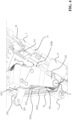
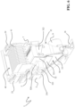
Figures 1-2 are schematic views of a low voltage switching device comprising a plurality of low voltage switch poles, according to the invention; and -
Figure 3 is a schematic exploded view of a switch pole, according to the invention; and -
Figure 4 is a partial view of a switch pole, according to the invention, in which only the movable contact assembly (without the claimed baffle arrangement) is shown; and -
Figures 5-6 are schematic views of a switch pole, according to different embodiments of the invention; and -
Figures 7-9 are schematic views the switch pole, according to the embodiment offigure 6 , in different operating conditions. - With reference to the attached figures, the present invention relates to a
switch pole 1 for a lowvoltage switching device 100, e.g., a circuit breaker, a disconnector, a contactor, or the like. - The
switching device 100 is particularly adapted for use in AC low voltage electrical systems and it will be described with reference to these applications. However, in principle, it may be used also in electric systems of different type, e.g., in DC low voltage electrical systems. - For the purposes of the present invention, the term "low voltage" typically relates to operating voltages up to 1,5 kV AC and 2 kV DC.
- The
switching device 100 comprises one ormore switch poles 1, according to the invention. - The number of switch poles may vary, according to the needs. In the embodiments shown in
figures 1-2 , theswitching device 100 is of the three-phase type and it comprises three switch poles. However, according to other embodiments of the invention (not shown), theswitching device 100 may include a different number of switch poles depending on the number of electric phases of the electric circuit, in which it must be installed. - Each
switch pole 1 of theswitching device 100 comprises aninsulating casing 2, which preferably defines an internal volume including acontact region 3 and an arcextinguishing region 4. - In general, the
contact region 3 is a portion of internal volume of the switch pole where the electric contacts of the switch pole are arranged and operate. On the other hand, the arc-extinguishing region 4 is a portion of internal volume of the switch pole where there are arranged arc-quenching means 41 designed to extinguish possible electric arcs arising between the electric contacts of the switch pole, during the opening manoeuvres of the switching device. - As shown in the cited figures, the
contact region 3 and thearc extinguishing region 4 of the switch pole are adjacent and in fluid-dynamic communication one with another. - Preferably, the
arc extinguishing region 4 is positioned at un upper level with respect to thecontact region 3, i.e., in proximal position relative to a top side of this latter. - For the sake of clarity, it is specified that relative terms used in this disclosure, e.g., "front", "rear", "lateral", "upper", "lower", "top" and "bottom" relate to the
switch pole 1 in its normal installation conditions, namely in the vertical installation shown infigures 1-2 . - The insulating
casing 2 of the switch pole is shaped as a contoured box with opposite first and secondlateral walls rear walls bottom walls - As shown in
figure 3 , the insulatingcasing 2 is preferably formed by first and second half shells coupled one to another. In practice, a first half shell comprises the firstlateral wall 21, a portion of thefront wall 23, a portion of therear wall 24 and a portion of thebottom wall 26, while a second half shell comprises the secondlateral wall 22, a portion of thefront wall 23, a portion of therear wall 24 and a portion of thebottom wall 26. - According to these embodiments of the invention, the
top wall 25 of the insulatingcasing 2 is fixed to a further insulatingenclosure 43 of another component (the arc chamber 40) of the switch pole and it may be removably installed in the switch pole together with such a component (figure 3 ). However, according to other embodiments of the invention (not shown), the insulatingcasing 2 of the switch pole may be arranged differently. For example, the top wall of the insulating casing may be integral with other walls of the insulating casing, or it may be self-standing so as to be removably couplable with other walls of the insulating casing. - Preferably, the
top wall 25 of the insulatingcasing 2 is provided with several through openings to allow the exit of hot gases from the internal space of the switch pole, namely from thearc extinguishing region 4, during an opening manoeuvre of the switching device. - According to some embodiments of the invention (shown in the cited figures), the insulating
casing 2 comprises an insulatingwall 5, which partially separates thecontact region 3 from thearc extinguishing region 4. - Conveniently, the insulating
wall 5 defines an insulating boundary between thecontact region 3 and thearc extinguishing region 4 at thefront wall 23 of the insulatingcasing 2 while thecontact region 3 and thearc extinguishing region 4 remain in direct fluid-dynamic communication at therear wall 24 of the insulatingcasing 2. This solution greatly helps to confine the electric arcs in the arc-extinguishingregion 4 of the switch pole during opening manoeuvres. - The insulating
casing 2 is made of an electrically insulating material, e.g., a thermosetting or thermoplastic material. - Advantageously, the
switch pole 1 comprises a first pole terminal 7 and asecond pole terminal 8. In operation, thepole terminals 7, 8 are electrically coupled with corresponding line conductors of an electric line. Such line conductors are, in turn, electrically connected to an electric power source (e.g., an electric power feeding or generation system or a section of electric grid) and to an electric load (e.g., an electric system or apparatus or a section of electric grid). - Preferably, the
pole terminals 7, 8 are positioned at therear wall 24 of the insulatingcasing 2 of the switch pole. - In general, the
pole terminals 7, 8 may be realized according to solutions of known type and it will be described hereinafter only with reference to the aspects of interest of the invention, for the sake of brevity. - The
switch pole 1 comprises a fixedcontact assembly 31 and amovable contact assembly 32, which are positioned in thecontact region 3 of the switch pole. - The fixed
contact assembly 31 comprises one or morefixed contacts 311, which are electrically connected to the first pole terminal 7 of the switch pole. - Preferably, the fixed
contacts 311 are positioned at therear wall 24 of the insulatingcasing 2, advantageously in proximal position relative to the arc-extinguishingregion 4 of the switch pole. Preferably, the fixedcontacts 311 are formed by suitable conductive plates. - In the embodiments shown in the cited figures, the fixed
contact assembly 31 comprises a pair of fixed contacts 311 (conductive tips or plates). However, according to other embodiments of the invention (not shown), the fixedcontact assembly 31 may include a different number of electric contacts. - In general, the fixed
contact assembly 31 may be realized according to solutions of known type and it will be described hereinafter only with reference to the aspects of interest of the invention, for the sake of brevity. - The
movable contact assembly 32 comprises one or moremovable contacts 321, which are electrically connected to thesecond pole terminal 8 of the switch pole. - Preferably, the
movable contacts 321 are formed by suitable conductive fingers. - The
movable contacts 321 can be mutually coupled or uncoupled to the fixedcontacts 311. To this aim, themovable contact assembly 32 is reversibly movable about a rotation axis A (figure 4 ). Referring tofigures 7-9 , the rotation axis A of themovable contact assembly 32 is perpendicular to the observation plane of these figures. In practice, it is parallel to the front andrear walls lateral walls casing 2. - The
movable contact assembly 32 is reversibly movable between a first position C (figure 7 ), in which themovable contacts 321 are coupled to the fixedcontacts 311, and second position O (figure 9 ), in which themovable contacts 321 are distally spaced from the fixedcontacts 311. The first position C of themovable contacts 321 of each switch pole corresponds to a closed condition of the switching device 100 (and of each switch pole), in which electric currents are allowed to flow along the electric poles whereas the second position O of themovable contacts 321 of each electric pole corresponds to an open condition of the switching device 100 (and of each switch pole), in which electric currents along the electric poles are interrupted. - A transition of the
movable contacts 321 of each switch pole from the above-mentioned first position to the above-mentioned second position constitute an opening manoeuvre of the switching device 100 (and of each switch pole) whereas an opposite transition of themovable contacts 321 of each switch pole from the above-mentioned second position to the above-mentioned first position constitute a closing manoeuvre of the switching device 100 (and of each switch pole). In the embodiments shown in the cited figures, themovable contact assembly 32 comprises a pair ofmovable contacts 321. However, according to other embodiments of the invention (not shown), themovable contact assembly 32 may include a different number of electric contacts. - The
movable contact assembly 32 comprises asupport body 322, preferably made of electrically insulating material, e.g., a thermosetting material. - The
support body 322 is rotatably coupled to the insulatingcasing 2 of the switch pole and it can rotate about the rotation axis A to allow coupling or separation of themovable contacts 321 to or from the corresponding fixedcontacts 311 of the fixedcontact assembly 31. - The
support body 322 supports themovable contacts 321 and one or moreelectrical connections 324 between thesecond pole terminal 8 and themovable contacts 321. - Preferably, the
electrical connections 324 are formed by flexible conductive braids. - The
movable contact assembly 32 comprises a connecting rod 323 (partially shown in the cited figures), which is fixed to thesupport body 322. In operation, the connectingrod 323 is mechanically coupled to a corresponding driving mechanism (not shown) located outside the switch pole. - The connecting
rod 323 protrudes from thesupport body 322 and it sticks out of the insulatingcasing 2 of the switch pole by passing through afront window 230 of thefront wall 23 of the insulatingcasing 2. - The
support body 322 has afirst side 322A facing thefront wall 23 of the insulating casing and asecond side 322B facing therear wall 23 of said insulating casing (figure 4 ). - The
support body 322 comprises, at thefirst side 322A, afirst side region 3221, from which said connectingrod 323 protrudes towards thefront window 230 of the insulatingcasing 2 and the outer environment, and asecond side region 3222, at which the above-mentioned electrical connections 324 (and possibly other conductive parts 325) are arranged. - Advantageously, the
first side region 3221 and thesecond side region 3222 of thesupport body 322 are arranged upwardly and downwardly relative thesupport body 322, i.e., in proximal position and in distal position relative to the arc-extinguishingregion 4 of the switch pole. - The
movable contacts 321 of the switch pole are arranged at thesecond side 322B of thesupport body 322. Conveniently, they are arranged upwardly relative to thesupport body 322, i.e., in proximal position relative to the arc-extinguishingregion 4 of the switch pole in such a way to face the corresponding fixedcontacts 311. - In general, the
movable contact assembly 32 may be realized according to solutions of known type and it will be described hereinafter only with reference to the aspects of interest of the invention, for the sake of brevity. - According to the embodiments shown in the cited figures, the
switch pole 1 comprises anarc chamber 40 positioned in thearc extinguishing region 4 of the switch pole, conveniently above thecontact region 3. - The
arc chamber 40 preferably comprises a plurality of arc-breakingelements 41 designed to extinguish possible electric arcs raising between theelectric contacts switching device 100. - The arc-breaking
elements 41 of thearc chamber 40 are preferably formed by arc-breaking plates arranged in parallel one to another, preferably along reference planes parallel to the front andrear walls casing 2. The arc-breakingplates 41 are advantageously arranged at subsequent positions between the front andrear walls casing 2, at increasing distances from therear wall 24. - Preferably, the
arc chamber 40 is formed by a self-standing structure that can be removably installed in the corresponding switch pole. In this case, thearc chamber 40 preferably comprises an insulating enclosure 43 (made of an electrically insulating material, e.g., a thermosetting or thermoplastic material), which can be removably fixed to the insulatingcasing 2. The arc-breakingelements 41 are conveniently fixed to the insulatingenclosure 43. - Preferably, the
top wall 25 of the insulatingcasing 2 is fixed to the insulatingcasing 43 of thearc chamber 40. In this way, it can be installed or removed together with thearc chamber 40. - According to other embodiments of the invention (not shown), however, the
arc chamber 40 may be simply formed by a sub-portion of thearc extinguishing region 4 of the switch pole, in which the arc-breakingelements 41 are arranged, for example by fixing them to thetop wall 25 of the insulatingcasing 2 through suitable supports. - In general, the
arc chamber 40 may be realized according to solutions of known type and it will be described hereinafter only with reference to the aspects of interest of the invention, for the sake of brevity. - According to the invention, the
switch pole 1 comprises abaffle arrangement 50 including one ormore sheets - The sheets of insulating
material movable contact assembly 32 in such a way to move together with this latter and be interposed between thesupport body 322 of said movable contact assembly and thefront wall 23 of the insulatingcasing 2. - The
baffle arrangement 50 is configured to form an insulating dielectric barrier between one or moreconductive parts movable contact assembly 32 and the connectingrod 323. The baffle arrangement can thus isolate electrically theconductive parts rod 323. In this way, the probability that undesired electric arcs strike between theconductive parts rod 323, during an opening manoeuvre of the switching device, is prevented or drastically limited. - The
baffle arrangement 50 is also configured to obstruct, at least partially, thefront window 230 of the insulatingcasing 2 at least when themovable contact assembly 32 reaches the above-mentioned second position O, during an opening manoeuvre of the switching device. - Preferably, one or more sheets of insulating
material front window 230 surrounding the connectingrod 323. - The
baffle arrangement 50 can thus segregate the internal volume of the switch pole from the outside environment, at thefront window 230, during an opening manoeuvre of the switching device. - In this way, it is possible to limit effectively leaks of hot gases through the
front window 230, thereby further reducing the probability of having arcing phenomena between theconductive parts movable contact assembly 32 and the connectingrod 323. - On the other hand, a more efficient confinement of hot gases within the arc-extinguishing
region 4 favors the flow of hot gases through thearc chamber 40 towards the openings of thetop wall 25 of the insulating casing. Electric arcs forming between theelectric contacts - According to some embodiments of the invention, the
baffle arrangement 50 is configured to obstruct, at least partially, thefront window 230, also when the opening manoeuvre of the switching device is not completed yet, before themovable contact assembly 32 reaches the above-mentioned second position O. - This solution allows confining more efficiently hot gases in the internal volume of the switch pole. According to some embodiments of the invention (
figures 5 and6 ), thebaffle arrangement 50 comprises one ormore sheets support body 322 at thefirst side 322A of this latter in such a way to form one piece with said movable contact assembly. These fixedsheets movable contact assembly 32, when this latter moves during the manoeuvres of the switching device. According to some embodiments of the invention (figure 6 ), thebaffle arrangement 50 comprises one ormore sheets 52 of insulating material mounted on the connectingrod 323 at thefirst side 322A of thesupport body 322 in such a way to be movable relative to themovable contact assembly 32. Thesemovable sheets 52 of insulating material generally move together with themovable contact assembly 32 during the manoeuvres of the switching device. However, under certain circumstances, they can move relative to themovable contact assembly 32. - Particularly, during an opening manoeuvre of the switching device, these
movable sheets 52 of insulating material are pushed towards thefront window 230 of the insulatingcasing 2 by the pressure exerted by hot gases flowing towards thefront window 230. Thesheets 52 of insulating material thus slide along the connectingrod 323 and reach thefront wall 23, while themovable contact assembly 32 is still moving. They can thus obstruct thefront window 230 before themovable contact assembly 32 reaches the second position O. - As shown in
figure 6 , thebaffle arrangement 50 may comprise the above-mentionedmovable sheets 52 of insulating material in addition to one or morefixed sheets 53 of insulating material. According to other variants (not shown), however, thebaffle arrangement 50 may comprise only the above-mentionedmovable sheets 52 of insulating material. - The one or
more sheets first side 322A of thesupport body 322 and thefront wall 23 of the insulatingcasing 2, when themovable contact assembly 32 reaches the second position O. Conveniently, the 51, 52, 53 of insulating material are structurally flexible to conform better to the profile of thefront wall 23. -
Figure 5 shows an embodiment of the invention, in which thebaffle arrangement 50 comprises a singlefirst sheet 51 of insulating material (e.g., a thermoplastic material) fixed on thesupport body 322 of the movable contact assembly. - Preferably, the first sheet of insulating
material 51 has a shape complementary to the profile of thefirst side 322A of thesupport body 322 in such a way to follow the outer surface of this latter. In this way, the first sheet of insulatingmaterial 51 does not limit the rotation angle of themovable contact assembly 32 when it is sandwiched between said movable contact assembly and thefront wall 23 of the insulating casing. - Preferably, the first sheet of insulating
material 51 has a deformable structure to conform better to the profile of thefront wall 23 when it is sandwiched between themovable contact assembly 32 and thefront wall 23. - The first sheet of insulating
material 51 comprises afirst sheet portion 511 covering thefirst side region 3221 of thesupport body 322 and fixed to this latter through suitable screws or equivalent mechanical connection means. Advantageously, thefirst sheet portion 511 comprises ahole 511A for the passage of the connectingrod 323, which protrudes from thesupport body 322. Conveniently, when themovable contact assembly 32 reaches the above-mentioned second position corresponding to an open condition of theswitching device 100, thefirst sheet portion 511 obstructs at least partially thefront window 230 of the insulatingcasing 2, thereby segregating the internal volume of the switch pole from the outer environment at thefront window 230. Preferably, thefirst sheet portion 511 obstructs the portions offront widow 230, which surround the connectingrod 323 and which are left free by the connectingrod 323, when this latter passes through thefront window 230. - The first sheet of insulating
material 51 additionally comprises asecond sheet portion 512 covering thesecond side region 3222 of thesupport body 322, at which theelectrical connections 324 are arranged. Thesecond sheet portion 512 is fixed to thesupport body 322 through suitable screws or equivalent mechanical connection means. - The
second sheet portion 512 is interposed between theelectrical connections 324 and the connectingrod 323, thereby electrically insulating this latter from said electrical connections.Figure 6 shows another embodiment of the invention. - In this case, the
baffle arrangement 50 comprises a plurality ofsecond sheets 52 of insulating material (e.g., made of paperboard or fiber glass) covering thefirst side region 3221 of thesupport body 322. - The
second sheets 52 of insulating material are mounted on the connectingrod 323 at thefirst side 322A of thesupport body 322 and are not fixed to thesupport body 322 so that they can move relative to themovable contact assembly 32 while they move together with this latter, particularly during an opening manoeuvre of the switching device. - Preferably, they are provided with a suitable hole or
aperture 520, through which the connectingrod 323 is inserted. In this way, they can be easily stacked one on another along said connecting rod. - As in the embodiment described above, the
second sheets 52 of insulating material obstruct at least partially thefront window 230 of the insulatingcasing 2, when themovable contact assembly 32 reaches the above-mentioned second position during an opening manoeuvre of the switching device. However, during the opening manoeuvre, one or moresecond sheets 52 of insulating material are pushed towards thefront window 230 of the insulatingcasing 2 by the incoming hot gases and obstruct at least partially thefront window 230 also before the opening manoeuvre is completed. - Preferably, the
second sheets 52 of insulating material have a shape complementary to the profile of thesupport body 322 at thefirst side region 3221 of said support body. - Preferably, the second sheets of insulating
material 52 have a deformable structure to conform better to the profile of thefront wall 23 when they are sandwiched between themovable contact assembly 32 and thefront wall 23. - In the embodiment of
figure 6 , thebaffle arrangement 50 further comprises athird sheet 53 of insulating material (e.g. made of a thermoplastic material) fixed to thesupport body 322 at thefirst side 322A of said support body. - The
third sheet 53 of insulating material covers thesecond side region 3222 of thesupport body 322 and it is interposed between theelectrical connections 324 and theconnected rod 324, thereby electrically insulating this latter from said electrical connections. - The
third sheet 53 of insulating material is fixed to thesupport body 322 through suitable screws or equivalent mechanical connection means. - Preferably, also the third sheet of insulating
material 53 has a deformable structure to conform better to the profile of thefront wall 23 when it is sandwiched between themovable contact assembly 32 and thefront wall 23. - Preferably, the
second sheets 52 of insulating material have lower free ends 521 partially overlapping with thethird sheet 53 of insulating material in such a way to be interposed between thethird sheet 53 of insulating material and the connecting rid 323. - This solution is quite useful as it allows simplifying the overall structure of the
movable contact assembly 32. In fact, connection elements 325 (e.g., screws), which are typically employed to support live parts (e.g. one or more partitioning members of theelectrical connections 324, which are fixed to the support body 322 -figures 4 and7-8 ) of the movable contact assembly, may be used also for fixing thethird sheet 53 of insulating material to thesupport body 322 without jeopardizing the electrical insulation of the connectingrod 323. -
Figures 7-9 show the behaviour of theswitch pole 1, according to the embodiment offigure 6 , during an opening manoeuvre of theswitching device 100. -
Figure 7 shows the switch pole with the movable contact assembly in the first position C. - The
movable contacts 321 are electrically and mechanically coupled to the fixedcontacts 311. In this situation, a current can flow along the switch pole between thepole terminals 7, 8. No electric arcs develop between the above-mentionedelectric contacts - During an opening manoeuvre, the
movable contact assembly 32 rotates about the rotation axis A and themovable contacts 321 are moved away from the fixed contacts 311 (figure 8 - dotted arrow). - As soon as the
movable contacts 321 separate from the fixedcontacts 311, a difference of voltage potential is established between said electric contacts (at any time, themovable contacts 321 may have a positive voltage polarity while the fixedcontacts 311 may have a negative voltage polarity, or vice-versa). Since the dielectric distance between theelectric contacts electric contacts front window 230 of the insulatingcasing 2. - Due to the pressure exerted by the hot gases, the
second sheets 52 of insulating are pushed towards thefront window 230. Thesecond sheets 52 of insulating slide along the connectingrod 323, while themovable contact assembly 32 is moving, and obstruct thefront window 230 before the movable contact assembly 32 (figure 8 ). The hot gases cannot flow through thefront window 230 and return towards thearc extinguishing region 4 of the switch pole. - In the meanwhile, both the second and
third sheets live parts rod 323. - Finally, when the
movable contact assembly 32 reaches the second position O, electric arcs may be finally quenched (figure 9 ) or continue their quenching process through the arc-chamber 40. - When the
movable contact assembly 32 reaches the second position O, both the second andthird sheets first side 322A of thesupport body 322 andfront wall 23 of the insulating casing. Thesecond sheets 52 of insulating material obstruct thefront window 230 while both the second andthird sheets live parts rod 323. - The operation of the
switch pole 1 according to the embodiment offigure 5 is quite similar. In this case, however, thefirst sheet 51 of insulating material does not move relative to themovable contact assembly 32 as it is fixed to thesupport body 322. - As the skilled person will certainly understand, the switch pole, according to the invention, may be subject to modifications or variations all falling within the scope of the inventive concept as defined by the appended claims.
- For example, according to a possible variant of the embodiment of
figure 5 , thebaffle arrangement 50 may include a plurality of overlappedsheets 51 of insulating material fixed to thesupport body 322 of the movable contact assembly. - As a further example, according to possible variants of the embodiment of
figure 6 , thebaffle arrangement 50 may include asingle sheet 52 of insulating material movably mounted on the connectingrod 323 and/or a plurality of overlappedsheets 53 of insulating material fixed to thesupport body 322 of the movable contact assembly. - The low voltage switch pole, according to the present invention, allow the proposed aims and the objects to be achieved.
- By virtue of the
baffle arrangement 50, in the switch pole, according to the present invention, the connectingrod 323 is electrically insulated from otherconductive parts movable contact assembly 32. At the same time, possible leaks of hot gases through thefront window 230 of the insulatingcasing 2 are prevented or drastically limited. - The formation of undesired arcing phenomena between the
conductive parts rod 323 is thus prevented or remarkably reduced in comparison to the available solutions of the state of the art. - Despite of the presence of the
baffle arrangement 50, theswitch pole 1 has a compact and simple structure. Theswitch pole 1 is thus relatively easy and cheap to manufacture at industrial level, at competitive costs with the available solutions of the state of the art. - As mentioned above, the present invention relates also to a low
voltage switching device 100 comprising one or more lowvoltage switch poles 1 as previously described. - With reference to
figures 1 and2 , a three-pole lowvoltage circuit breaker 100 comprising three lowvoltage switch poles 1 is shown. - In this embodiment, the insulating
casing 2 of eachswitch pole 1 is made of two half shells, and theswitch poles 1 are positioned side by side in a supporting structure havingrigid flanks 101 as well as acover portion 102. - From suitable
front windows 230 at thefront wall 23 of the insulatingcasing 2 of eachswitch pole 1, connectingrods 323 protrude for mechanical connection with a driving mechanism (not shown). As it is possible to notice fromfigure 2 , thebaffle arrangement 50 of each switch pole obstructs thefront window 230 of the corresponding insulatingcasing 2, when theswitching device 100 has reached an open condition (as shown infigure 2 ). - The general structure of the low
voltage circuit breaker 100 is, in many aspects, well known in the art and therefore it will not be described here in more details, for the sake of brevity.
Claims (11)
- A switch pole (1) for a low voltage switching device (100) comprising:- an insulating casing (2) defining an internal space of said switch pole and having opposite front and rear walls (23, 24), said first and second pole terminals being arranged at the rear wall (24) of said insulating casing;- a fixed contact assembly (31) and a movable contact assembly (32) positioned in said contact region (3) and including, respectively, one or more fixed contacts (311) and one or more movable contacts (321), which can be mutually coupled or uncoupled, said movable contact assembly being reversibly movable, about a rotation axis (A), between a first position (C), in which said movable contacts are coupled to said fixed contacts, and a second position (O), in which said movable contacts are spaced apart from said fixed contacts;wherein said movable contact assembly (32) comprises:- a support body (322) configured to support said movable contacts (321), said support body having a first side (322A) facing the front wall (23) of said insulating casing, and a second side (322B) facing the rear wall (24) of said insulating casing, said movable contacts (321) being located at the second side of said support body;- a connecting rod (323) fixed to said support body and mechanically couplable to a driving mechanism of said movable contact assembly outside said switch pole, said connecting rod protruding from the first side (322A) of said support body and sticking out of the insulating casing (2) of said switch pole by passing through a front window (230) of the front wall (23) of said insulating casing;characterised in that said switch pole (1) comprises a baffle arrangement (50) including one or more sheets (51, 52, 53) of insulating material arranged on said movable contact assembly (32) at the first side (322A) of said support body (322), said one or more sheets of insulating material moving together with said movable contact assembly (32) and being interposed between said support body (322) and the front wall (23) of said insulating casing,wherein said one or more sheets (51, 52, 53) of insulating material form an insulating dielectric barrier between one or more conductive parts (324, 325) of said movable contact assembly (32) and said connecting rod (323),wherein said one or more sheets (51, 52) of insulating material obstruct at least partially said front window (230), during an opening manoeuvre of said switching device, at least when said movable contact assembly (32) reaches said second position (O).
- Switch pole, according to claim 1, characterised in that said one or more sheets (52) of insulating material obstruct at least partially said front window (230), during an opening manoeuvre of said switching device, also before said movable contact assembly (32) reaches said second position (O).
- Switch pole, according to one of the previous claims, characterised in that said baffle arrangement (50) comprises one or more sheets (51, 53) of insulating material fixed to said support body (322) at the first side (322A) of said support body.
- Switch pole, according to one of the previous claims, characterised in that said baffle arrangement (50) comprises one or more sheets (52) of insulating material mounted on said connecting rod (323) at the first side (322A) of said support body in such a way to be movable relative to said movable contact assembly (32).
- Switch pole, according to claim 3, characterised in that said baffle arrangement (50) comprises a first sheet (51) of insulating material fixed to said support body (322) at the first side (322A) of said support body, said first sheet of insulating material having a first sheet portion (511) covering a first side region (3221) of said support body, from which said connecting rod (323) protrudes, and a second sheet portion (512) covering a second side region (3222) of said support body, at which said conductive parts (324) are arranged.
- Switch pole, according to claim 5, characterised in that said sheet (51) of insulating material have a shape complementary to a profile of said support body (322) at the first side (322A) of said support body.
- Switch pole, according to claims 3 and 4, characterised in that said baffle arrangement (50) comprises:- a plurality of second sheets (52) of insulating material mounted on said connecting rod (323) at the first side (322A) of said support body and movable relative to said movable contact assembly (32), said second sheets (52) of insulating material being stacked one on another along a direction parallel to said connecting rod (323) and covering the first side region (3221) of said support body;- a third sheet (53) of insulating material fixed to said support body (322) at the first side (322A) of said support body, said third sheet (53) of insulating material covering the second side region (3222) of said support body.
- Switch pole, according to claim 7, characterised in that said second sheets (52) of insulating material have a shape complementary to a profile of said support body (322) at the first side region (3221) of said support body.
- Switch pole, according to one of the claims from 7 to 8, characterised in that said second sheets (52) of insulating material have a free end (521) partially overlapping said third sheet (53) of insulating material in such a way to be interposed between said third sheet (53) of insulating material and said connecting rod (323).
- Switch pole, according to one of the previous claims, characterised in that it comprises an arc chamber (40) positioned in said arc extinguishing region (4) and comprising a plurality of arc-breaking elements (41).
- A low voltage switching device (100) characterized in that it comprises at least a switch pole (1), according to one of the previous claims.
Priority Applications (3)
| Application Number | Priority Date | Filing Date | Title |
|---|---|---|---|
| EP23164401.4A EP4439603A1 (en) | 2023-03-27 | 2023-03-27 | Low voltage switch pole with a baffle arrangement |
| CN202410243858.4A CN118712026A (en) | 2023-03-27 | 2024-03-04 | Low voltage switch pole |
| US18/618,028 US20240331957A1 (en) | 2023-03-27 | 2024-03-27 | Low Voltage Switch Pole |
Applications Claiming Priority (1)
| Application Number | Priority Date | Filing Date | Title |
|---|---|---|---|
| EP23164401.4A EP4439603A1 (en) | 2023-03-27 | 2023-03-27 | Low voltage switch pole with a baffle arrangement |
Publications (1)
| Publication Number | Publication Date |
|---|---|
| EP4439603A1 true EP4439603A1 (en) | 2024-10-02 |
Family
ID=85776108
Family Applications (1)
| Application Number | Title | Priority Date | Filing Date |
|---|---|---|---|
| EP23164401.4A Pending EP4439603A1 (en) | 2023-03-27 | 2023-03-27 | Low voltage switch pole with a baffle arrangement |
Country Status (3)
| Country | Link |
|---|---|
| US (1) | US20240331957A1 (en) |
| EP (1) | EP4439603A1 (en) |
| CN (1) | CN118712026A (en) |
Citations (4)
| Publication number | Priority date | Publication date | Assignee | Title |
|---|---|---|---|---|
| EP0222690A1 (en) * | 1985-11-13 | 1987-05-20 | Siemens Aktiengesellschaft | Contact arrangement for low-voltage circuit breakers with a movable insulating body |
| US4827231A (en) * | 1988-01-28 | 1989-05-02 | Westinghouse Electric Corp. | Molded case circuit breaker with viewing window and sliding barrier |
| EP0489986B1 (en) * | 1990-12-14 | 1995-03-08 | Siemens Aktiengesellschaft | Low tension high power circuit breaker with an insulating connection means and an insulating shield |
| EP3048625A1 (en) * | 2015-01-23 | 2016-07-27 | ABB S.p.A. | Low voltage switch pole |
-
2023
- 2023-03-27 EP EP23164401.4A patent/EP4439603A1/en active Pending
-
2024
- 2024-03-04 CN CN202410243858.4A patent/CN118712026A/en active Pending
- 2024-03-27 US US18/618,028 patent/US20240331957A1/en active Pending
Patent Citations (4)
| Publication number | Priority date | Publication date | Assignee | Title |
|---|---|---|---|---|
| EP0222690A1 (en) * | 1985-11-13 | 1987-05-20 | Siemens Aktiengesellschaft | Contact arrangement for low-voltage circuit breakers with a movable insulating body |
| US4827231A (en) * | 1988-01-28 | 1989-05-02 | Westinghouse Electric Corp. | Molded case circuit breaker with viewing window and sliding barrier |
| EP0489986B1 (en) * | 1990-12-14 | 1995-03-08 | Siemens Aktiengesellschaft | Low tension high power circuit breaker with an insulating connection means and an insulating shield |
| EP3048625A1 (en) * | 2015-01-23 | 2016-07-27 | ABB S.p.A. | Low voltage switch pole |
Also Published As
| Publication number | Publication date |
|---|---|
| CN118712026A (en) | 2024-09-27 |
| US20240331957A1 (en) | 2024-10-03 |
Similar Documents
| Publication | Publication Date | Title |
|---|---|---|
| US5905242A (en) | High voltage hybrid circuit-breaker | |
| USRE37244E1 (en) | Insulated type switching device | |
| CN106848909A (en) | One kind is without isolated switchgear under bin static contact non-SF 6 gas insulative | |
| KR101562482B1 (en) | A switching device and a switchgear | |
| US20150014279A1 (en) | Device For Protection Against Particles Generated By An Electric Switching Arc | |
| US4388506A (en) | Circuit interrupter | |
| EP2541573A1 (en) | Carrier link insulator for a circuit breaker | |
| SE440573B (en) | CAPSLAT STELLVERK | |
| CN113517155B (en) | A vacuum isolation arc extinguishing device | |
| CN112309783B (en) | Door phase separation device in molded case circuit breaker | |
| EP3843117B1 (en) | Load-break switch without sf6 gas having a vacuum circuit interrupter for medium-voltage switching systems | |
| US20240331957A1 (en) | Low Voltage Switch Pole | |
| ES2865422T3 (en) | Switching device with double conductive housing | |
| GB2042263A (en) | Improvements in or relating to circuit interrupters | |
| CN106848908A (en) | One kind is without bin static contact non-SF 6 gas insulative switchgear | |
| US11688570B2 (en) | Switching device | |
| US20240266127A1 (en) | Low-voltage switch pole | |
| US12362113B2 (en) | Low voltage switch pole | |
| US12087525B2 (en) | Low voltage switch pole | |
| EP4459653B1 (en) | A switching apparatus for electrical systems | |
| CN207021580U (en) | One kind is without bin static contact non-SF 6 gas insulative switchgear | |
| EP4435815A1 (en) | A switching apparatus for medium voltage electrical systems | |
| US12444557B2 (en) | Low voltage switch pole | |
| WO2013159278A1 (en) | Fixation and encapsulation type vacuum switch cabinet with solid insulating assembly | |
| RU2609567C1 (en) | High-voltage circuit breaker |
Legal Events
| Date | Code | Title | Description |
|---|---|---|---|
| PUAI | Public reference made under article 153(3) epc to a published international application that has entered the european phase |
Free format text: ORIGINAL CODE: 0009012 |
|
| STAA | Information on the status of an ep patent application or granted ep patent |
Free format text: STATUS: THE APPLICATION HAS BEEN PUBLISHED |
|
| AK | Designated contracting states |
Kind code of ref document: A1 Designated state(s): AL AT BE BG CH CY CZ DE DK EE ES FI FR GB GR HR HU IE IS IT LI LT LU LV MC ME MK MT NL NO PL PT RO RS SE SI SK SM TR |
|
| STAA | Information on the status of an ep patent application or granted ep patent |
Free format text: STATUS: REQUEST FOR EXAMINATION WAS MADE |
|
| 17P | Request for examination filed |
Effective date: 20250326 |