EP4439529A1 - Oscillating apparatus and control method for oscillating apparatus - Google Patents
Oscillating apparatus and control method for oscillating apparatus Download PDFInfo
- Publication number
- EP4439529A1 EP4439529A1 EP22918866.9A EP22918866A EP4439529A1 EP 4439529 A1 EP4439529 A1 EP 4439529A1 EP 22918866 A EP22918866 A EP 22918866A EP 4439529 A1 EP4439529 A1 EP 4439529A1
- Authority
- EP
- European Patent Office
- Prior art keywords
- expansion
- contraction
- screw shaft
- contraction portion
- driving source
- Prior art date
- Legal status (The legal status is an assumption and is not a legal conclusion. Google has not performed a legal analysis and makes no representation as to the accuracy of the status listed.)
- Pending
Links
Images



Classifications
-
- G—PHYSICS
- G09—EDUCATION; CRYPTOGRAPHY; DISPLAY; ADVERTISING; SEALS
- G09B—EDUCATIONAL OR DEMONSTRATION APPLIANCES; APPLIANCES FOR TEACHING, OR COMMUNICATING WITH, THE BLIND, DEAF OR MUTE; MODELS; PLANETARIA; GLOBES; MAPS; DIAGRAMS
- G09B9/00—Simulators for teaching or training purposes
- G09B9/02—Simulators for teaching or training purposes for teaching control of vehicles or other craft
- G09B9/08—Simulators for teaching or training purposes for teaching control of vehicles or other craft for teaching control of aircraft, e.g. Link trainer
- G09B9/12—Motion systems for aircraft simulators
- G09B9/14—Motion systems for aircraft simulators controlled by fluid actuated piston or cylinder ram
-
- G—PHYSICS
- G09—EDUCATION; CRYPTOGRAPHY; DISPLAY; ADVERTISING; SEALS
- G09B—EDUCATIONAL OR DEMONSTRATION APPLIANCES; APPLIANCES FOR TEACHING, OR COMMUNICATING WITH, THE BLIND, DEAF OR MUTE; MODELS; PLANETARIA; GLOBES; MAPS; DIAGRAMS
- G09B9/00—Simulators for teaching or training purposes
- G09B9/02—Simulators for teaching or training purposes for teaching control of vehicles or other craft
- G09B9/08—Simulators for teaching or training purposes for teaching control of vehicles or other craft for teaching control of aircraft, e.g. Link trainer
- G09B9/12—Motion systems for aircraft simulators
-
- B—PERFORMING OPERATIONS; TRANSPORTING
- B25—HAND TOOLS; PORTABLE POWER-DRIVEN TOOLS; MANIPULATORS
- B25J—MANIPULATORS; CHAMBERS PROVIDED WITH MANIPULATION DEVICES
- B25J19/00—Accessories fitted to manipulators, e.g. for monitoring, for viewing; Safety devices combined with or specially adapted for use in connection with manipulators
- B25J19/06—Safety devices
- B25J19/066—Redundant equipment
-
- B—PERFORMING OPERATIONS; TRANSPORTING
- B25—HAND TOOLS; PORTABLE POWER-DRIVEN TOOLS; MANIPULATORS
- B25J—MANIPULATORS; CHAMBERS PROVIDED WITH MANIPULATION DEVICES
- B25J9/00—Program-controlled manipulators
- B25J9/003—Program-controlled manipulators having parallel kinematics
- B25J9/0063—Program-controlled manipulators having parallel kinematics with kinematics chains having an universal joint at the base
- B25J9/0069—Program-controlled manipulators having parallel kinematics with kinematics chains having an universal joint at the base with kinematics chains of the type universal-prismatic-universal
-
- B—PERFORMING OPERATIONS; TRANSPORTING
- B25—HAND TOOLS; PORTABLE POWER-DRIVEN TOOLS; MANIPULATORS
- B25J—MANIPULATORS; CHAMBERS PROVIDED WITH MANIPULATION DEVICES
- B25J9/00—Program-controlled manipulators
- B25J9/10—Program-controlled manipulators characterised by positioning means for manipulator elements
- B25J9/102—Gears specially adapted therefor, e.g. reduction gears
-
- G—PHYSICS
- G09—EDUCATION; CRYPTOGRAPHY; DISPLAY; ADVERTISING; SEALS
- G09B—EDUCATIONAL OR DEMONSTRATION APPLIANCES; APPLIANCES FOR TEACHING, OR COMMUNICATING WITH, THE BLIND, DEAF OR MUTE; MODELS; PLANETARIA; GLOBES; MAPS; DIAGRAMS
- G09B9/00—Simulators for teaching or training purposes
- G09B9/02—Simulators for teaching or training purposes for teaching control of vehicles or other craft
- G09B9/04—Simulators for teaching or training purposes for teaching control of vehicles or other craft for teaching control of land vehicles
Definitions
- the present disclosure relates to an oscillation device such as a Stewart platform applied to a driving simulator or a flight simulator, and a method for controlling the oscillation device.
- a Stewart platform applied to a driving simulator or the like is configured by installing six actuators between a lower support plate and an upper support plate.
- the Stewart platform controls an angle of the upper support plate with respect to the lower support plate by operating the six actuators.
- an upper support plate is supported by a lower support plate by six actuators. Therefore, for example, when an operation abnormality occurs in one actuator among six actuators, it becomes difficult to control the upper support plate to an appropriate angle.
- the number of actuators is increased or a plurality of driving sources are provided for one actuator.
- an increase in the number of driving sources causes the device to be increased in size or to be increased in cost.
- the present disclosure has been made to solve the problems described above, and an object of the present disclosure is to provide an oscillation device and a method for controlling an oscillation device capable of suppressing an increase in size and an increase in cost and improving safety.
- An oscillation device of the present disclosure for achieving the above object is an oscillation device in which a plurality of expansion and contraction devices disposed between a first member and a second member disposed to face each other, in which the expansion and contraction device includes a first expansion and contraction portion that is capable of expanding and contracting between the first member and the second member, a second expansion and contraction portion that is capable of expanding and contracting between the first member and the second member, and a common driving source that supplies power to the first expansion and contraction portion and the second expansion and contraction portion.
- a control method for an oscillation device is a control method for an oscillation device in which a plurality of expansion and contraction devices are disposed between a first member and a second member disposed to face each other, the expansion and contraction device includes a first expansion and contraction portion that is capable of expanding and contracting between the first member and the second member, a second expansion and contraction portion that is capable of expanding and contracting between the first member and the second member, and a common driving source that supplies power to the first expansion and contraction portion and the second expansion and contraction portion, the method includes, when an operation abnormality occurs in any one of the first expansion and contraction portion and the second expansion and contraction portion, controlling an amount of expansion and contraction of the other of the first expansion and contraction portion and the second expansion and contraction portion by the driving source.
- an oscillation device and a control method of the oscillation device of the present disclosure it is possible to suppress an increase in size and an increase in cost and to improve safety.
- the present disclosure is not limited to the embodiment.
- the present disclosure also includes configurations obtained by combining each embodiment.
- constituents in the embodiment include constituents that are easily perceivable by those skilled in the art, constituents that are substantially the same, and constituents within a so-called range of equivalents.
- Fig. 1 is a perspective view showing an overall configuration of an oscillation device according to a first embodiment.
- the oscillation device 10 is configured to have a plurality of expansion and contraction devices 13 disposed between the first member 11 and the second member 12 disposed to face each other.
- the oscillation device 10 is, for example, a Stewart platform, and has six expansion and contraction devices 13.
- the oscillation device 10 is not limited to the Stewart platform, and the number of the expansion and contraction devices 13 may be five or less or may be seven or more.
- the oscillation device 10 is applied to, for example, a simulator device such as a driving simulator or a flight simulator, a robot hand, or the like, but is not limited thereto.
- six expansion and contraction devices 13 are configured into three sets, each set including two expansion and contraction devices 13 as one set.
- One set of two expansion and contraction device 13 is disposed in a chevron shape.
- each of the base end portions is connected to the different connection portions 21 and 22 of the first member 11 via universal joints 23 and 24.
- each of the tip portions is connected to the connection portion 25 common to the second members 12 via universal joints 26 and 27.
- the base end portion is connected to the vicinity of the base end portion of the other adjacent one set of two expansion and contraction devices 13.
- the six expansion and contraction devices 13 have the same configuration.
- each of the base end portions may be connected to a common connection portion, or each of the tip portions may be connected to different connection portions 25.
- the oscillation device 10 can change and adjust the angle of the second member 12 with respect to the first member 11 by controlling an amount of expansion and contraction of the plurality of expansion and contraction devices 13. At this time, at least the amount of expansion and contraction in one set of the two expansion and contraction devices 13 is controlled in synchronization with each other.
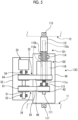
- Fig. 2 is a schematic view showing the expansion and contraction device in the oscillation device.
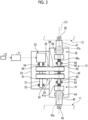
- the expansion and contraction device 13 includes a first expansion and contraction portion 31, a second expansion and contraction portion 32, a driving source 33, a first power transmission system 34, and a second power transmission system 35.
- the first expansion and contraction portion 31 and the second expansion and contraction portion 32 are capable of expanding and contracting between the first member 11 and the second member 12.
- the first expansion and contraction portion 31 and the second expansion and contraction portion 32 are disposed in a series state between the first member 11 and the second member 12.
- the first expansion and contraction portion 31 and the second expansion and contraction portion 32 are accommodated in the first housing 40.
- the first expansion and contraction portion 31 has a first screw shaft 41 and a first moving body 42.
- a screw portion 41a is formed in a tip portion of the first screw shaft 41.
- a screw hole 42a penetrating the base end portion is formed in the first moving body 42.
- the first expansion and contraction portion 31 is configured such that the screw portion 41a of the first screw shaft 41 is screwed into the screw hole 42a of the first moving body 42.
- the first screw shaft 41 is rotatable in the circumferential direction by the bearing 43 with respect to the first housing 40 and is supported to be immovable in the axial direction.
- the first moving body 42 is movable in the axial direction by the guide member 44 and is supported not to be rotatable in the circumferential direction. A part of the first expansion and contraction portion 31 on the tip portion side of the first moving body 42 protrudes from the first housing 40.
- the first moving body 42 is provided with a connection portion 45 at a tip portion, and the connection portion 45 is connected to the first member 11 via universal joints 23 and 24 (refer to Fig. 1 ).
- the second expansion and contraction portion 32 has a second screw shaft 46 and a second moving body 47.
- the screw portion 46a is formed in a tip portion of the second screw shaft 46.
- the screw hole 47a penetrating the base end portion is formed in the second moving body 47.
- the second expansion and contraction portion 32 is configured such that the screw portion 46a of the second screw shaft 46 is screwed into the screw hole 47a of the second moving body 47.
- the second screw shaft 46 is rotatable in the circumferential direction by the bearing 48 with respect to the first housing 40 and is supported to be immovable in the axial direction.
- the second moving body 47 is movable in the axial direction by the guide member 49 and is supported not to be rotatable in the circumferential direction.
- a part of the second expansion and contraction portion 32 on the tip portion side of the second moving body 47 protrudes from the first housing 40.
- the second moving body 47 is provided with a connection portion 50 at a tip portion, and the connection portion 50 is connected to the second member 12 via universal joints 26 and 27 (refer to Fig. 1 ).
- the first expansion and contraction portion 31 and the second expansion and contraction portion 32 are disposed along a center O1 at which the centers of the first screw shaft 41 and the second screw shaft 46 are common.
- the first expansion and contraction portion 31 when the first screw shaft 41 is rotated in the normal direction, power is transmitted to the first moving body 42 via the screw portion 41a and the screw hole 42a that are screwed to each other, and the first moving body 42 moves to one side in the axial direction and is separated from the first screw shaft 41.
- the first expansion and contraction portion 31 when the first screw shaft 41 is rotated in the reverse direction, power is transmitted to the first moving body 42 via the screw portion 41a and the screw hole 42a that are screwed to each other, and the first moving body 42 moves in the other side in the axial direction and approaches the first screw shaft 41.
- the second expansion and contraction portion 32 when the second screw shaft 46 is rotated in the normal direction, power is transmitted to the second moving body 47 via the screw portion 46a and the screw hole 47a that are screwed to each other, and the second moving body 47 moves to one side in the axial direction and is separated from the second screw shaft 46.
- the second expansion and contraction portion 32 when the second screw shaft 46 is rotated in the reverse direction, power is transmitted to the second moving body 47 via the screw portion 46a and the screw hole 47a that are screwed with each other, and the second moving body 47 moves to the other side in the axial direction and approaches the second screw shaft 46.
- the driving source 33 is, for example, an electric or hydraulic motor.
- the driving source 33 has a rotary shaft 51 as an output shaft.
- the driving source 33 is accommodated in and fixed to the second housing 52.
- the second housing 52 is fixed to the first housing 40.
- the rotary shaft 51 is rotatably supported by the bearing 53 and 54 in the circumferential direction with respect to the second housing 52.
- the driving source 33 can rotate the rotary shaft 51 in a normal direction and a reverse direction.
- the driving source 33 functions as a common driving source that supplies power to the first expansion and contraction portion 31 and the second expansion and contraction portion 32.
- the first power transmission system 34 has a drive pulley 61, a driven pulley 62, and a drive belt 63.
- the drive pulley 61 is fixed to the rotary shaft 51 of the driving source 33.
- the driven pulley 62 is fixed to the first screw shaft 41 in the first expansion and contraction portion 31.
- the drive belt 63 is an endless belt and is wound between the drive pulley 61 and the driven pulley 62.
- the first power transmission system 34 is capable of rotating the first screw shaft 41 by transmitting the power of the driving source 33 between the driving source 33 and the first screw shaft 41.
- the second power transmission system 35 has a drive pulley 64, a driven pulley 65, and a drive belt 66.
- the drive pulley 64 is fixed to the rotary shaft 51 of the driving source 33.
- the driven pulley 65 is fixed to the second screw shaft 46 in the second expansion and contraction portion 32.
- the drive belt 66 is an endless belt and is wound between the drive pulley 64 and the driven pulley 65.
- the second power transmission system 35 is capable of rotating the second screw shaft 46 by transmitting the power of the driving source 33 between the driving source 33 and the second screw shaft 46.
- the driving source 33 when the driving source 33 is driven and the rotary shaft 51 is rotated in the normal direction, power is transmitted to the first screw shaft 41 via the drive pulley 61, the drive belt 63, and the driven pulley 62 that configure the first power transmission system 34, and the first screw shaft 41 is rotated in the normal direction.
- the power of the driving source 33 is transmitted to the second screw shaft 46 via the drive pulley 64, the drive belt 66, and the driven pulley 65 that configure the second power transmission system 35, and the second screw shaft 46 is rotated in the normal direction.
- the driving source 33 when the driving source 33 is driven and the rotary shaft 51 is rotated in the reverse direction, power is transmitted to the first screw shaft 41 via the drive pulley 61, the drive belt 63, and the driven pulley 62 that configure the first power transmission system 34, and the first screw shaft 41 is rotated in the reverse direction.
- the power of the driving source 33 is transmitted to the second screw shaft 46 via the drive pulley 64, the drive belt 66, and the driven pulley 65 that configure the second power transmission system 35, and the second screw shaft 46 is rotated in the reverse direction.
- the oscillation device 10 (refer to Fig. 1 ) includes a control unit 71.
- the control unit 71 can control each expansion and contraction device 13 via the driving source 33. That is, the control unit 71 controls the expansion and contraction direction and the amount of expansion and contraction of each expansion and contraction device 13 by adjusting the rotation direction, the rotation speed, the rotation amount, and the like of the driving source 33.
- the control unit 71 controls the driving source 33 according to the input command value or the various stored programs.
- the control unit 71 is a controller, is configured to include, for example, a central processing unit (CPU), a micro processing unit (MPU), or the like, and executes various programs.
- Each of the expansion and contraction devices 13 is provided with an operation abnormality detection unit 72 that detects an operation abnormality such as the first expansion and contraction portion 31 or the second expansion and contraction portion 32.
- the operation abnormality detection unit 72 detects a failure of the first expansion and contraction portion 31 and the second expansion and contraction portion 32, a failure of the first power transmission system 34 and the second power transmission system 35, a failure of each brake device (not shown) provided in the first expansion and contraction portion 31 and the second expansion and contraction portion 32, and the like.
- the operation abnormality detection unit 72 is, for example, a rotation sensor that detects the rotation amount of the first screw shaft 41 or the second screw shaft 46, a stroke sensor that detects the moving amount of the first moving body 42 or the second moving body 47, a rotation sensor that detects the rotation amount of the drive pulleys 61 and 64 or the driven pulleys 62 and 65, or an acceleration sensor that detects the moving speed of the drive belts 63 and 66, but is not limited to these sensors.
- the control unit 71 controls the driving source 33 based on a detection result of the operation abnormality detection unit 72.
- the control unit 71 controls the amount of expansion and contraction of the other of the first expansion and contraction portion 31 and the second expansion and contraction portion 32 by the driving source 33.
- the control unit 71 When the angle of the second member 12 with respect to the first member 11 is changed, the control unit 71 operates each of the expansion and contraction devices 13.
- the control unit 71 drives the driving source 33 to rotate the rotary shaft 51 in the normal direction.
- the power of the driving source 33 is transmitted to the first expansion and contraction portion 31 via the first power transmission system 34, and the first screw shaft 41 is rotated in the normal direction.
- a rotational force is transmitted to the first moving body 42 as an axial movement force via the screw portion 41a and the screw hole 42a, and the first moving body 42 is separated from the first screw shaft 41.
- the power of the driving source 33 is transmitted to the second screw shaft 46 of the second expansion and contraction portion 32 via the second power transmission system 35, and the second screw shaft 46 is rotated in the normal direction.
- a rotational force is transmitted to the second moving body 47 as an axial movement force via the screw portion 46a and the screw hole 47a, and the second moving body 47 is separated from the second screw shaft 46.
- the expansion and contraction device 13 can change the angle of the second member 12 with respect to the first member 11 by expanding the first moving body 42 and the second moving body 47 outward in the axial direction with respect to the first housing 40 and the second housing 52.
- the control unit 71 drives the driving source 33 to rotate the rotary shaft 51 in the reverse direction
- the power of the driving source 33 is transmitted to the first expansion and contraction portion 31 via the first power transmission system 34
- the first screw shaft 41 is rotated in the reverse direction.
- a rotational force is transmitted to the first moving body 42 as an axial movement force via the screw portion 41a and the screw hole 42a, and the first moving body 42 approaches the first screw shaft 41.
- the power of the driving source 33 is transmitted to the second screw shaft 46 of the second expansion and contraction portion 32 via the second power transmission system 35, and the second screw shaft 46 is rotated in the reverse direction.
- a rotational force is transmitted to the second moving body 47 as an axial movement force via the screw portion 46a and the screw hole 47a, and the second moving body 47 approaches the second screw shaft 46.
- the first moving body 42 and the second moving body 47 can be contracted inward in the axial direction with respect to the first housing 40 and the second housing 52 and the angle of the second member 12 with respect to the first member 11 can be changed, as the expansion and contraction device 13.
- the operation abnormality detection unit 72 of the expansion and contraction device 13 detects the operation abnormality of the first expansion and contraction portion 31, the operation abnormality detection unit 72 outputs to the control unit 71 that the first expansion and contraction portion 31 is in operation abnormality.
- the control unit 71 controls the driving source 33 in accordance with the operation abnormality of the first expansion and contraction portion 31 detected by the operation abnormality detection unit 72, and controls the amount of expansion of the second expansion and contraction portion 32.
- the control unit 71 expands the second expansion and contraction portion 32 by in a range of 6 strokes to 10 strokes by the driving source 33.
- the maximum purpose is to prevent the second member 12 from falling due to the operation abnormality of the first expansion and contraction portion 31.
- the control unit 71 controls the driving source 33 to increase the amount of expansion of the second expansion and contraction portion 32 within a range in which the falling of the second member 12 can be prevented.
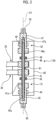
- Fig. 3 is a cross-sectional view showing a modification example of the expansion and contraction device.
- the expansion and contraction device 13A includes a first expansion and contraction portion 31, a second expansion and contraction portion 32, a driving source 33 (refer to Fig. 2 ), a first power transmission system 34, and a second power transmission system 35.
- the driving source 33, the first power transmission system 34, and the second power transmission system 35 are the same as those in the first embodiment.
- the first expansion and contraction portion 31 and the second expansion and contraction portion 32 are capable of expanding and contracting between the first member 11 and the second member 12.
- the first expansion and contraction portion 31 and the second expansion and contraction portion 32 are disposed in a series state between the first member 11 and the second member 12.
- the first expansion and contraction portion 31 has a first screw shaft 41 and a first moving body 42.
- the second expansion and contraction portion 32 has a second screw shaft 46 and a second moving body 47.
- the first expansion and contraction portion 31 and the second expansion and contraction portion 32 are disposed along a center O1 at which the centers of the first screw shaft 41 and the second screw shaft 46 are common. Then, the first screw shaft 41 and the second screw shaft 46 are disposed with a common guide shaft 81.
- the first screw shaft 41 has a cylindrical shape, and a through-hole along the axial direction is formed in the first screw shaft 41.
- the second screw shaft 46 has a cylindrical shape, and a through-hole along the axial direction is formed in the second screw shaft 46.
- the guide shaft 81 is inserted into the through-hole of the first screw shaft 41 and the through-hole of the second screw shaft 46.
- each of axial end portions of the guide shaft 81 is inserted into the first moving body 42 and the second moving body 47, and the connection portion 82 is connected to the first moving body 42.
- the connection portion 82 of the guide shaft 81 may be connected to the second moving body 47, and the connection portion 82 may be connected to the first screw shaft 41 or the second screw shaft 46.
- the first expansion and contraction portion 31 and the second expansion and contraction portion 32 are supported to be movable in the axial direction by at least the first screw shaft 41 and the second screw shaft 46 by a common guide shaft 81. Therefore, for example, even when an operation abnormality occurs in the first expansion and contraction portion 31, the first screw shaft 41 or the like is not broken, and the second expansion and contraction portion 32, which is not an operation abnormality, operates smoothly, so that the falling of the second member 12 can be appropriately prevented.
- Fig. 4 is a schematic view showing an expansion and contraction device in the oscillation device of a second embodiment.
- the same reference numerals are assigned to the members having the same functions as the members in the first embodiment described above, and the detailed description thereof will be omitted.
- the expansion and contraction device 13B includes a first expansion and contraction portion 31, a second expansion and contraction portion 32, a driving source 33, a first power transmission system 34, and a second power transmission system 35.
- the driving source 33, the first power transmission system 34, and the second power transmission system 35 are the same as those in the first embodiment.
- the first expansion and contraction portion 31 and the second expansion and contraction portion 32 are capable of expanding and contracting between the first member 11 and the second member 12.
- the first expansion and contraction portion 31 and the second expansion and contraction portion 32 are disposed in a parallel state between the first member 11 and the second member 12.
- the first expansion and contraction portion 31 and the second expansion and contraction portion 32 are accommodated in the first housing 40.
- the first expansion and contraction portion 31 has a first screw shaft 41 and a first moving body 42.
- the second expansion and contraction portion 32 has a second screw shaft 46 and a second moving body 47.
- the first expansion and contraction portion 31 and the second expansion and contraction portion 32 are substantially the same as those in the first embodiment.
- the reduction ratio between the screw portion 41a of the first screw shaft 41 constituting the first expansion and contraction portion 31 and the screw hole 42a of the first moving body 42 and the reduction ratio between the screw portion 46a of the second screw shaft 46 constituting the second expansion and contraction portion 32 and the screw hole 47a of the second moving body 47 are the same.
- the first expansion and contraction portion 31 and the second expansion and contraction portion 32 are disposed side by side. A part of each of the first moving body 42 and the second moving body 47 on the tip portion side protrudes from the first housing 40 in the first expansion and contraction portion 31 and the second expansion and contraction portion 32.
- the connecting member 91 is connected to each tip portion of the first moving body 42 and the second moving body 47, the connecting member 91 is provided with a connection portion 92, and the connection portion 92 is connected to the second member 12 via a universal joint 26 and 27 (refer to Fig. 1 ).
- the first expansion and contraction portion 31 and the second expansion and contraction portion 32 are provided with connection portions 93 at the end portion of the first housing 40 in which the first screw shaft 41 and the second screw shaft 46 are supported, and the connection portions 93 are connected to the first member 11 via the universal joints 23 and 24 (refer to Fig. 1 ).
- each of the expansion and contraction devices 13B is operated.
- the driving source 33 is driven to rotate the rotary shaft 51 in the normal direction.
- the power of the driving source 33 is transmitted to the first expansion and contraction portion 31 via the first power transmission system 34, and the first screw shaft 41 is rotated in the normal direction.
- the power of the driving source 33 is transmitted to the second screw shaft 46 of the second expansion and contraction portion 32 via the second power transmission system 35, and the second screw shaft 46 is rotated in the normal direction.
- the expansion and contraction device 13B operates with the first expansion and contraction portion 31 and the second expansion and contraction portion 32 disposed in parallel with each other being synchronized with each other by a common driving source 33. That is, the amount of expansion of the first expansion and contraction portion 31 and the amount of expansion of the second expansion and contraction portion 32 are the same. As a result, the first moving body 42 and the second moving body 47 can be expanded outward in the axial direction with respect to the first housing 40 and the second housing 52 and the angle of the second member 12 with respect to the first member 11 can be changed, as the expansion and contraction device 13B.
- the first expansion and contraction portion 31 of the expansion and contraction device 13B occurs the operation abnormality.
- the first expansion and contraction portion 31 and the second expansion and contraction portion 32 are disposed in parallel between the first member 11 and the second member 12. Therefore, even when the operation abnormality occurs in the first expansion and contraction portion 31, the second expansion and contraction portion 32 operates normally, so that the angle of the second member 12 can be appropriately changed and the second member 12 is prevented from falling.
- Fig. 5 is a schematic view showing an expansion and contraction device in the oscillation device of a third embodiment.
- the same reference numerals are assigned to the members having the same functions as the members in the first embodiment described above, and the detailed description thereof will be omitted.
- the expansion and contraction device 13C includes a first expansion and contraction portion 101, a second expansion and contraction portion 102, a driving source 33, a first power transmission system 34, and a second power transmission system 35.
- the driving source 33, the first power transmission system 34, and the second power transmission system 35 are the same configurations as those in the first embodiment.
- the first expansion and contraction portion 101 and the second expansion and contraction portion 102 are capable of expanding and contracting between the first member 11 and the second member 12.
- the first expansion and contraction portion 101 and the second expansion and contraction portion 102 are disposed in a parallel state between the first member 11 and the second member 12.
- the first expansion and contraction portion 101 and the second expansion and contraction portion 102 are accommodated in the first housing 40.
- the first expansion and contraction portion 101 has a screw shaft 111 and a moving body 112.
- a screw portion 111a is formed in a tip portion of the screw shaft 111.
- the screw hole 112a penetrating the base end portion is formed in the moving body 112.
- the first expansion and contraction portion 101 is configured such that the screw portion 111a of the screw shaft 111 is screwed into the screw hole 112a of the moving body 112.
- the screw shaft 111 is rotatable in the circumferential direction by the bearing 113 with respect to the first housing 40 and is supported to be immovable in the axial direction.
- the moving body 112 is movable in the axial direction by the guide member 114 and is supported not to be rotatable in the circumferential direction. A part of the moving body 112 on the tip portion side protrudes from the first housing 40.
- the moving body 112 is provided with a connection portion 115 at a tip portion, and the connection portion 115 is connected to the second member 12 via universal joints 26 and 27 (refer to Fig. 1 ).
- the second expansion and contraction portion 102 includes a moving body 112 and a driven pulley 116 as a cylindrical member.
- the moving body 112 is also used as a component of the first expansion and contraction portion 101 and the second expansion and contraction portion 102.
- a screw portion 112b is formed in a base end outer peripheral portion of the moving body 112.
- a screw hole 116a penetrating in the axial direction is formed in the driven pulley 116.
- the second expansion and contraction portion 102 is configured such that the screw portion 112b of the moving body 112 is screwed into the screw hole 116a of the driven pulley 116.
- the reduction ratio between the screw portion 111a of the screw shaft 111 constituting the first expansion and contraction portion 101 and the screw hole 112a of the moving body 112 and the reduction ratio between the screw portion 112b of the moving body 112 constituting the second expansion and contraction portion 102 and the screw hole 116a of the driven pulley 116 are the same.
- the first expansion and contraction portion 101 and the second expansion and contraction portion 102 are provided with connection portions 117 at the end portion of the first housing 40 in which the screw shaft 111 and the driven pulley 116 are supported, and the connection portions 117 are connected to the first member 11 via the universal joints 23 and 24 (refer to Fig. 1 ).
- the moving body 112 when the screw shaft 111 is rotated in the normal direction, power is transmitted to the moving body 112 via the screw portion 111a and the screw hole 112a that are screwed to each other, and the moving body 112 moves to one side in the axial direction and is separated from the screw shaft 111.
- the screw shaft 111 when the screw shaft 111 is rotated in the reverse direction, power is transmitted to the moving body 112 via the screw portion 111a and the screw hole 112a that are screwed to each other, and the moving body 112 moves to the other side in the axial direction and approaches the screw shaft 111.
- the second expansion and contraction portion 102 when the driven pulley 116 is rotated in the normal direction, power is transmitted to the moving body 112 via the screw hole 116a and the screw portion 112b that are screwed to each other, and the moving body 112 moves to one side in the axial direction and is separated from the driven pulley 116.
- the driven pulley 116 when the driven pulley 116 is rotated in the reverse direction, power is transmitted to the moving body 112 via the screw hole 116a and the screw portion 112b that are screwed to each other, and the moving body 112 moves to the other side in the axial direction and approaches the driven pulley 116.
- the driving source 33 has a rotary shaft 51.
- the driving source 33 is accommodated in and fixed to the second housing 52.
- the second housing 52 is fixed to the first housing 40.
- the first power transmission system 34 has a drive pulley 61, a driven pulley 62, and a drive belt 63.
- the second power transmission system 35 has a drive pulley 64, a driven pulley 116, and a drive belt 66.
- the drive belt 66 is wound between the drive pulley 64 and the driven pulley 116.
- the second power transmission system 35 is capable of rotating the driven pulley 116 by transmitting the power of the driving source 33 between the driving source 33 and the driven pulley 116.
- each of the expansion and contraction devices 13C is operated.
- the driving source 33 is driven to rotate the rotary shaft 51 in the normal direction.
- the power of the driving source 33 is transmitted to the first expansion and contraction portion 101 via the first power transmission system 34, and the screw shaft 111 is rotated in the normal direction.
- the power of the driving source 33 is transmitted to the driven pulley 116 of the second expansion and contraction portion 32 via the second power transmission system 35, and the driven pulley 116 is rotated in the normal direction.
- the expansion and contraction device 13C operates with the first expansion and contraction portion 101 and the second expansion and contraction portion 102 disposed in parallel with each other being synchronized with each other by a common driving source 33.
- the moving body 112 can be expanded outward in the axial direction with respect to the first housing 40 and the second housing 52 and the angle of the second member 12 with respect to the first member 11 can be changed, as the expansion and contraction device 13C.
- the first expansion and contraction portion 101 of the expansion and contraction device 13C occurs the operation abnormality.
- the first expansion and contraction portion 101 and the second expansion and contraction portion 102 are disposed in parallel between the first member 11 and the second member 12. Therefore, even when the operation abnormality occurs in the first expansion and contraction portion 101, the second expansion and contraction portion 102 operates normally, so that the angle of the second member 12 can be appropriately changed and the second member 12 is prevented from falling.
- Fig. 6 is a front view showing a main part of the expansion and contraction device in the oscillation device of the fourth embodiment
- Fig. 7 is a plan view showing the main part of the expansion and contraction device.
- the same reference numerals are assigned to the members having the same functions as the members in the first embodiment described above, and the detailed description thereof will be omitted.
- the first power transmission system 34A is a modification example of the first power transmission system 34 in each of the above-described embodiments.
- the first power transmission system 34A can also be applied as a modification example of the second power transmission system 35 in each of the above-described embodiments.
- the first power transmission system 34B has a first power transmission path 141 and a second power transmission path 142.
- the first power transmission path 141 and the second power transmission path 142 are power transmission paths of different types, respectively.
- the first power transmission path 141 includes a drive pulley 61, a driven pulley 62, and a drive belt 63.
- the drive pulley 61 is fixed to the rotary shaft 121
- the driven pulley 62 is fixed to the rotary shaft 122.
- the drive belt 63 is wound between the drive pulley 61 and the driven pulley 62.
- the first power transmission path 141 is capable of transmitting power of the rotary shaft 121 to rotate the rotary shaft 122.
- the second power transmission path 142 includes the drive gear 131, the driven gear 132, and a plurality of (three in the present embodiment) intermediate gears 133, 134, and 135.
- the drive gear 131 is fixed to the rotary shaft 121
- the driven gear 132 is fixed to the rotary shaft 122.
- the intermediate gears 133, 134, and 135 are fixed to the rotary shafts 123, 124, and 125.
- the drive gear 131 and the intermediate gears 133, 134, and 135 and the driven gear 132 mesh with each other.
- the second power transmission path 142 is capable of transmitting power of the rotary shaft 121 to the rotary shaft 122.
- the first power transmission path 141 and the second power transmission path 142 operate in synchronization with each other and rotate the rotary shaft 122 by a rotational force of the rotary shaft 121. Therefore, the second power transmission path 142 is set such that the rotation amount (rotation speed) of the first power transmission path 141 and the second power transmission path 142 transmitted from the rotary shaft 121 to the rotary shaft 122 is the same.
- the diameter or the number of teeth of the drive gear 131, the driven gear 132, and the intermediate gears 133, 134, and 135 is set.
- the power of the rotary shaft 121 can be transmitted to the rotary shaft 122 by the second power transmission path 142.
- the operation abnormality such as the intermediate gears 133, 134, and 135 of the second power transmission path 142 being damaged occurs, the power of the rotary shaft 121 can be transmitted to the rotary shaft 122 by the first power transmission path 141.
- the oscillation device 10 includes a plurality of expansion and contraction devices 13, 13A, 13B, and 13C disposed between a first member 11 and a second member 12 disposed to face each other, in which the expansion and contraction devices 13, 13A, 13B, and 13C include first expansion and contraction portions 31 and 101 that are capable of expanding and contracting between the first member 11 and the second member 12, second expansion and contraction portions 32 and 102 that are capable of expanding and contracting between the first member 11 and the second member 12, and a common driving source 33 that supplies power to the first expansion and contraction portions 31 and 101 and the second expansion and contraction portions 32 and 102.
- the first expansion and contraction portions 31 and 101 and the second expansion and contraction portions 32 and 102 that are driven by the common driving source 33 are provided. Therefore, each of the expansion and contraction devices 13, 13A, 13B, and 13C disposed between the first member 11 and the second member 12 has redundancy. Therefore, even when an operation abnormality occurs in one of the first expansion and contraction portions 31 and 101 and the second expansion and contraction portions 32 and 102, the other can operate normally, so that it is possible to suppress the falling and improve safety.
- the first expansion and contraction portions 31 and 101 and the second expansion and contraction portions 32 and 102 are driven by the common driving source 33, it is possible to suppress an increase in size and an increase in cost.
- the first expansion and contraction portion 31 and the second expansion and contraction portion 32 are disposed in series between the first member 11 and the second member 12. Accordingly, the first expansion and contraction portion 31 and the second expansion and contraction portion 32 are disposed in series with each other, so that a large space in the lateral direction can be secured in the first expansion and contraction portion 31 and the second expansion and contraction portion 32, and the lateral compactification of the expansion and contraction devices 13, 13A, 13B, and 13C can be achieved.
- the first expansion and contraction portions 31 and 101 and the second expansion and contraction portions 32 and 102 are disposed in parallel between the first member 11 and the second member 12. Accordingly, the first expansion and contraction portion 31 and the second expansion and contraction portion 32 are disposed in parallel with each other, so that the length of the first expansion and contraction portion 31 and the second expansion and contraction portion 32 in the vertical direction can be shortened, and the vertical compactification of the expansion and contraction devices 13, 13A, 13B, and 13C can be achieved.
- the oscillation device is the oscillation device in which the first expansion and contraction portion 31 has a first screw shaft 41 and a first moving body 42 that is screwed to a screw portion 41a of the first screw shaft 41 and is movable in an axial direction, the second expansion and contraction portion 32 has a second screw shaft 46 and a second moving body 47 that is screwed to a screw portion 46a of the second screw shaft 46 and is movable in the axial direction, a first power transmission system 34 that transmits power of the driving source 33 to the first screw shaft 41 to rotate the first screw shaft 41 is provided between the driving source 33 and the first screw shaft 41, and a second power transmission system 35 that transmits power of the driving source 33 to the second screw shaft 46 to rotate the second screw shaft 46 is provided between the driving source 33 and the second screw shaft 46. Accordingly, the power of the driving source 33 can be appropriately transmitted to the first expansion and contraction portion 31 and the second expansion and contraction portion 32 by the first power transmission system 34 and the second power transmission system 35.
- the first screw shaft 41 and the second screw shaft 46 are disposed in a straight line, and a common guide shaft 81 is disposed in the first screw shaft 41 and the second screw shaft 46. Accordingly, even when the first screw shaft 41 or the second screw shaft 46 is broken, the first expansion and contraction portion 31 and the second expansion and contraction portion 32 are maintained in a series relationship by the guide shaft 81, and thus it is possible to appropriately prevent the falling.
- a base end portion side of the first screw shaft 41 and the second screw shaft 46 is connected to one of the first member 11 and the second member 12, and a tip portion of the first moving body 42 and the second moving body 47 is connected to the connecting member 91 and is connected to the other of the first member 11 and the second member 12 via the connecting member 91. Accordingly, the first expansion and contraction portion 31 and the second expansion and contraction portion 32 can be disposed in parallel with each other, and even when one of the first screw shaft 41 and the second screw shaft 46 is broken, the other can secure the amount of expansion and contraction, and thus it is possible to appropriately prevent the falling.
- the oscillation device is the oscillation device in which the first expansion and contraction portion 101 has a screw shaft 111 and a moving body 112 that is screwed to a screw portion 11a of the screw shaft 111 and is movable in an axial direction, the second expansion and contraction portion 102 has a moving body 112 and a driven pulley (cylindrical member) 116 that is screwed to a screw portion 112b of the moving body 112 and is movable in the axial direction, a first power transmission system 34 that transmits power of the driving source 33 to the screw shaft 111 to rotate the screw shaft 111 is provided between the driving source 33 and the screw shaft 111, and a second power transmission system 35 that transmits power of the driving source 33 to the driven pulley 116 to rotate the driven pulley 116 is provided between the driving source 33 and the driven pulley 116.
- first expansion and contraction portion 101 and the second expansion and contraction portion 102 are also being used as the configuration member and are disposed in parallel, so that the size thereof can be reduced, and even when one of the screw shaft 111 and the driven pulley 116 is broken, the other can secure the amount of expansion and contraction, and thus it is possible to appropriately prevent the falling.
- the first power transmission systems 34 and 34A and the second power transmission system 35 are provided with power transmission paths of different types, respectively. Accordingly, redundancy can be secured in the first power transmission systems 34 and 34A and the second power transmission system 35, and safety can be improved.
- the oscillation device includes an operation abnormality detection unit 72 that detects an operation abnormality of the first expansion and contraction portions 31 and 101 and the second expansion and contraction portions 32 and 102, and control unit 71 that controls the driving source 33 based on a detection result of the operation abnormality detection unit 72, in which, when the operation abnormality detection unit 72 detects the operation abnormality of any one of the first expansion and contraction portions 31 and 101 and the second expansion and contraction portions 32 and 102, the control unit 71 controls an amount of expansion and contraction of any other of the first expansion and contraction portions 31 and 101 and the second expansion and contraction portions 32 and 102 by the driving source 33. Accordingly, even when an operation abnormality occurs in one of the first expansion and contraction portions 31 and 101 and the second expansion and contraction portions 32 and 102, the other can operate normally, so that it is possible to suppress the falling and improve safety.
- a method for controlling an oscillation device in which a plurality of expansion and contraction devices 13, 13A, 13B, and 13C are disposed between a first member 11 and a second member 12 disposed to face each other, the expansion and contraction devices 13, 13A, 13B, and 13C include first expansion and contraction portions 31 and 101 that are capable of expanding and contracting between the first member 11 and the second member 12, second expansion and contraction portions 32 and 102 that are capable of expanding and contracting between the first member 11 and the second member 12, and a common driving source 33 that supplies power to the first expansion and contraction portions 31 and 101 and the second expansion and contraction portions 32 and 102, the method includes, when an operation abnormality occurs in any one of the first expansion and contraction portions 31 and 101 and the second expansion and contraction portions 32 and 102, controlling an amount of expansion and contraction of any other of the first expansion and contraction portions 31 and 101 and the second expansion and contraction portions 32 and 102 by the driving source 33.
- the method for controlling the oscillation device According to the method for controlling the oscillation device according to the tenth aspect, even when an operation abnormality occurs in one of the first expansion and contraction portions 31 and 101 and the second expansion and contraction portions 32 and 102, the other can operate normally, so that it is possible to suppress the falling and improve safety.
- the first expansion and contraction portions 31 and 101 and the second expansion and contraction portions 32 and 102 are driven by the common driving source 33, it is possible to suppress an increase in size and an increase in cost.
- the first power transmission system 34 and the second power transmission system 35 are configured by the pulley and the drive belt.
- the first power transmission system 34 and the second power transmission system 35 may be configured by, for example, a gear mechanism.
Landscapes
- Engineering & Computer Science (AREA)
- Theoretical Computer Science (AREA)
- Aviation & Aerospace Engineering (AREA)
- Business, Economics & Management (AREA)
- Physics & Mathematics (AREA)
- Educational Administration (AREA)
- Educational Technology (AREA)
- General Physics & Mathematics (AREA)
- Robotics (AREA)
- Mechanical Engineering (AREA)
- Transmission Devices (AREA)
Abstract
Description
- The present disclosure relates to an oscillation device such as a Stewart platform applied to a driving simulator or a flight simulator, and a method for controlling the oscillation device.
- A Stewart platform applied to a driving simulator or the like is configured by installing six actuators between a lower support plate and an upper support plate. The Stewart platform controls an angle of the upper support plate with respect to the lower support plate by operating the six actuators. As such a technique, for example, there is one described in the following patent literature.
-
- [PTL 1]
UK Patent Application Publication No. 2328192 - [PTL 2] International Publication No.
WO2016/172029 - In the Stewart platform, an upper support plate is supported by a lower support plate by six actuators. Therefore, for example, when an operation abnormality occurs in one actuator among six actuators, it becomes difficult to control the upper support plate to an appropriate angle. In the above-mentioned patent literature, the number of actuators is increased or a plurality of driving sources are provided for one actuator. However, in such a configuration, there is a problem in that an increase in the number of driving sources causes the device to be increased in size or to be increased in cost.
- The present disclosure has been made to solve the problems described above, and an object of the present disclosure is to provide an oscillation device and a method for controlling an oscillation device capable of suppressing an increase in size and an increase in cost and improving safety.
- An oscillation device of the present disclosure for achieving the above object is an oscillation device in which a plurality of expansion and contraction devices disposed between a first member and a second member disposed to face each other, in which the expansion and contraction device includes a first expansion and contraction portion that is capable of expanding and contracting between the first member and the second member, a second expansion and contraction portion that is capable of expanding and contracting between the first member and the second member, and a common driving source that supplies power to the first expansion and contraction portion and the second expansion and contraction portion.
- A control method for an oscillation device according to the present disclosure is a control method for an oscillation device in which a plurality of expansion and contraction devices are disposed between a first member and a second member disposed to face each other, the expansion and contraction device includes a first expansion and contraction portion that is capable of expanding and contracting between the first member and the second member, a second expansion and contraction portion that is capable of expanding and contracting between the first member and the second member, and a common driving source that supplies power to the first expansion and contraction portion and the second expansion and contraction portion, the method includes, when an operation abnormality occurs in any one of the first expansion and contraction portion and the second expansion and contraction portion, controlling an amount of expansion and contraction of the other of the first expansion and contraction portion and the second expansion and contraction portion by the driving source. Advantageous Effects of Invention
- According to an oscillation device and a control method of the oscillation device of the present disclosure, it is possible to suppress an increase in size and an increase in cost and to improve safety.
-
-
Fig. 1 is a perspective view showing an overall configuration of an oscillation device according to a first embodiment. -
Fig. 2 is a schematic view showing the expansion and contraction device in the oscillation device. -
Fig. 3 is a cross-sectional view showing a modification example of the expansion and contraction device. -
Fig. 4 is a schematic view showing the expansion and contraction device in the oscillation device of a second embodiment. -
Fig. 5 is a schematic view showing the expansion and contraction device in the oscillation device of a third embodiment. -
Fig. 6 is a front view showing a main part of the expansion and contraction device in the oscillation device of a fourth embodiment. -
Fig. 7 is a plan view showing a main part of the expansion and contraction device. - Hereinafter, a preferred embodiment of the present disclosure will be described in detail with reference to the drawings. The present disclosure is not limited to the embodiment. In addition, in a case where there are a plurality of embodiments, the present disclosure also includes configurations obtained by combining each embodiment. In addition, constituents in the embodiment include constituents that are easily perceivable by those skilled in the art, constituents that are substantially the same, and constituents within a so-called range of equivalents.
-
Fig. 1 is a perspective view showing an overall configuration of an oscillation device according to a first embodiment. - In the first embodiment, as shown in
Fig. 1 , theoscillation device 10 is configured to have a plurality of expansion andcontraction devices 13 disposed between thefirst member 11 and thesecond member 12 disposed to face each other. Theoscillation device 10 is, for example, a Stewart platform, and has six expansion andcontraction devices 13. However, theoscillation device 10 is not limited to the Stewart platform, and the number of the expansion andcontraction devices 13 may be five or less or may be seven or more. Theoscillation device 10 is applied to, for example, a simulator device such as a driving simulator or a flight simulator, a robot hand, or the like, but is not limited thereto. - For example, six expansion and
contraction devices 13 are configured into three sets, each set including two expansion andcontraction devices 13 as one set. One set of two expansion andcontraction device 13 is disposed in a chevron shape. In one set of the expansion andcontraction devices 13, each of the base end portions is connected to thedifferent connection portions first member 11 viauniversal joints contraction devices 13, each of the tip portions is connected to theconnection portion 25 common to thesecond members 12 viauniversal joints contraction devices 13, the base end portion is connected to the vicinity of the base end portion of the other adjacent one set of two expansion andcontraction devices 13. The six expansion andcontraction devices 13 have the same configuration. In addition, in one set of the expansion andcontraction devices 13, each of the base end portions may be connected to a common connection portion, or each of the tip portions may be connected todifferent connection portions 25. - The
oscillation device 10 can change and adjust the angle of thesecond member 12 with respect to thefirst member 11 by controlling an amount of expansion and contraction of the plurality of expansion andcontraction devices 13. At this time, at least the amount of expansion and contraction in one set of the two expansion andcontraction devices 13 is controlled in synchronization with each other. -
Fig. 2 is a schematic view showing the expansion and contraction device in the oscillation device. - As shown in
Fig. 2 , the expansion andcontraction device 13 includes a first expansion andcontraction portion 31, a second expansion andcontraction portion 32, adriving source 33, a firstpower transmission system 34, and a secondpower transmission system 35. - The first expansion and
contraction portion 31 and the second expansion andcontraction portion 32 are capable of expanding and contracting between thefirst member 11 and thesecond member 12. The first expansion andcontraction portion 31 and the second expansion andcontraction portion 32 are disposed in a series state between thefirst member 11 and thesecond member 12. The first expansion andcontraction portion 31 and the second expansion andcontraction portion 32 are accommodated in thefirst housing 40. - The first expansion and
contraction portion 31 has afirst screw shaft 41 and a first movingbody 42. Ascrew portion 41a is formed in a tip portion of thefirst screw shaft 41. Ascrew hole 42a penetrating the base end portion is formed in the first movingbody 42. The first expansion andcontraction portion 31 is configured such that thescrew portion 41a of thefirst screw shaft 41 is screwed into thescrew hole 42a of the first movingbody 42. - The
first screw shaft 41 is rotatable in the circumferential direction by thebearing 43 with respect to thefirst housing 40 and is supported to be immovable in the axial direction. The first movingbody 42 is movable in the axial direction by theguide member 44 and is supported not to be rotatable in the circumferential direction. A part of the first expansion andcontraction portion 31 on the tip portion side of the first movingbody 42 protrudes from thefirst housing 40. The first movingbody 42 is provided with aconnection portion 45 at a tip portion, and theconnection portion 45 is connected to thefirst member 11 viauniversal joints 23 and 24 (refer toFig. 1 ). - The second expansion and
contraction portion 32 has asecond screw shaft 46 and a second movingbody 47. Thescrew portion 46a is formed in a tip portion of thesecond screw shaft 46. Thescrew hole 47a penetrating the base end portion is formed in the second movingbody 47. The second expansion andcontraction portion 32 is configured such that thescrew portion 46a of thesecond screw shaft 46 is screwed into thescrew hole 47a of the second movingbody 47. - The
second screw shaft 46 is rotatable in the circumferential direction by the bearing 48 with respect to thefirst housing 40 and is supported to be immovable in the axial direction. The second movingbody 47 is movable in the axial direction by theguide member 49 and is supported not to be rotatable in the circumferential direction. A part of the second expansion andcontraction portion 32 on the tip portion side of the second movingbody 47 protrudes from thefirst housing 40. The second movingbody 47 is provided with aconnection portion 50 at a tip portion, and theconnection portion 50 is connected to thesecond member 12 viauniversal joints 26 and 27 (refer toFig. 1 ). - The first expansion and
contraction portion 31 and the second expansion andcontraction portion 32 are disposed along a center O1 at which the centers of thefirst screw shaft 41 and thesecond screw shaft 46 are common. - Therefore, in the first expansion and
contraction portion 31, when thefirst screw shaft 41 is rotated in the normal direction, power is transmitted to the first movingbody 42 via thescrew portion 41a and thescrew hole 42a that are screwed to each other, and the first movingbody 42 moves to one side in the axial direction and is separated from thefirst screw shaft 41. On the other hand, in the first expansion andcontraction portion 31, when thefirst screw shaft 41 is rotated in the reverse direction, power is transmitted to the first movingbody 42 via thescrew portion 41a and thescrew hole 42a that are screwed to each other, and the first movingbody 42 moves in the other side in the axial direction and approaches thefirst screw shaft 41. - In the second expansion and
contraction portion 32, when thesecond screw shaft 46 is rotated in the normal direction, power is transmitted to the second movingbody 47 via thescrew portion 46a and thescrew hole 47a that are screwed to each other, and the second movingbody 47 moves to one side in the axial direction and is separated from thesecond screw shaft 46. On the other hand, in the second expansion andcontraction portion 32, when thesecond screw shaft 46 is rotated in the reverse direction, power is transmitted to the second movingbody 47 via thescrew portion 46a and thescrew hole 47a that are screwed with each other, and the second movingbody 47 moves to the other side in the axial direction and approaches thesecond screw shaft 46. - The driving
source 33 is, for example, an electric or hydraulic motor. The drivingsource 33 has arotary shaft 51 as an output shaft. The drivingsource 33 is accommodated in and fixed to thesecond housing 52. Thesecond housing 52 is fixed to thefirst housing 40. Therotary shaft 51 is rotatably supported by thebearing second housing 52. The drivingsource 33 can rotate therotary shaft 51 in a normal direction and a reverse direction. The drivingsource 33 functions as a common driving source that supplies power to the first expansion andcontraction portion 31 and the second expansion andcontraction portion 32. - The first
power transmission system 34 has adrive pulley 61, a drivenpulley 62, and adrive belt 63. Thedrive pulley 61 is fixed to therotary shaft 51 of the drivingsource 33. The drivenpulley 62 is fixed to thefirst screw shaft 41 in the first expansion andcontraction portion 31. Thedrive belt 63 is an endless belt and is wound between thedrive pulley 61 and the drivenpulley 62. The firstpower transmission system 34 is capable of rotating thefirst screw shaft 41 by transmitting the power of the drivingsource 33 between the drivingsource 33 and thefirst screw shaft 41. - The second
power transmission system 35 has adrive pulley 64, a drivenpulley 65, and adrive belt 66. Thedrive pulley 64 is fixed to therotary shaft 51 of the drivingsource 33. The drivenpulley 65 is fixed to thesecond screw shaft 46 in the second expansion andcontraction portion 32. Thedrive belt 66 is an endless belt and is wound between thedrive pulley 64 and the drivenpulley 65. The secondpower transmission system 35 is capable of rotating thesecond screw shaft 46 by transmitting the power of the drivingsource 33 between the drivingsource 33 and thesecond screw shaft 46. - Therefore, when the driving
source 33 is driven and therotary shaft 51 is rotated in the normal direction, power is transmitted to thefirst screw shaft 41 via thedrive pulley 61, thedrive belt 63, and the drivenpulley 62 that configure the firstpower transmission system 34, and thefirst screw shaft 41 is rotated in the normal direction. In addition, the power of the drivingsource 33 is transmitted to thesecond screw shaft 46 via thedrive pulley 64, thedrive belt 66, and the drivenpulley 65 that configure the secondpower transmission system 35, and thesecond screw shaft 46 is rotated in the normal direction. - On the other hand, when the driving
source 33 is driven and therotary shaft 51 is rotated in the reverse direction, power is transmitted to thefirst screw shaft 41 via thedrive pulley 61, thedrive belt 63, and the drivenpulley 62 that configure the firstpower transmission system 34, and thefirst screw shaft 41 is rotated in the reverse direction. In addition, the power of the drivingsource 33 is transmitted to thesecond screw shaft 46 via thedrive pulley 64, thedrive belt 66, and the drivenpulley 65 that configure the secondpower transmission system 35, and thesecond screw shaft 46 is rotated in the reverse direction. - In addition, the oscillation device 10 (refer to
Fig. 1 ) includes acontrol unit 71. Thecontrol unit 71 can control each expansion andcontraction device 13 via the drivingsource 33. That is, thecontrol unit 71 controls the expansion and contraction direction and the amount of expansion and contraction of each expansion andcontraction device 13 by adjusting the rotation direction, the rotation speed, the rotation amount, and the like of the drivingsource 33. Thecontrol unit 71 controls the drivingsource 33 according to the input command value or the various stored programs. Thecontrol unit 71 is a controller, is configured to include, for example, a central processing unit (CPU), a micro processing unit (MPU), or the like, and executes various programs. - Each of the expansion and
contraction devices 13 is provided with an operationabnormality detection unit 72 that detects an operation abnormality such as the first expansion andcontraction portion 31 or the second expansion andcontraction portion 32. The operationabnormality detection unit 72 detects a failure of the first expansion andcontraction portion 31 and the second expansion andcontraction portion 32, a failure of the firstpower transmission system 34 and the secondpower transmission system 35, a failure of each brake device (not shown) provided in the first expansion andcontraction portion 31 and the second expansion andcontraction portion 32, and the like. The operationabnormality detection unit 72 is, for example, a rotation sensor that detects the rotation amount of thefirst screw shaft 41 or thesecond screw shaft 46, a stroke sensor that detects the moving amount of the first movingbody 42 or the second movingbody 47, a rotation sensor that detects the rotation amount of the drive pulleys 61 and 64 or the drivenpulleys drive belts - The
control unit 71 controls the drivingsource 33 based on a detection result of the operationabnormality detection unit 72. When the operationabnormality detection unit 72 detects the operation abnormality in any one of the first expansion andcontraction portion 31 and the second expansion andcontraction portion 32, thecontrol unit 71 controls the amount of expansion and contraction of the other of the first expansion andcontraction portion 31 and the second expansion andcontraction portion 32 by the drivingsource 33. - When the angle of the
second member 12 with respect to thefirst member 11 is changed, thecontrol unit 71 operates each of the expansion andcontraction devices 13. Thecontrol unit 71 drives the drivingsource 33 to rotate therotary shaft 51 in the normal direction. The power of the drivingsource 33 is transmitted to the first expansion andcontraction portion 31 via the firstpower transmission system 34, and thefirst screw shaft 41 is rotated in the normal direction. When thefirst screw shaft 41 is rotated in the normal direction, a rotational force is transmitted to the first movingbody 42 as an axial movement force via thescrew portion 41a and thescrew hole 42a, and the first movingbody 42 is separated from thefirst screw shaft 41. In addition, the power of the drivingsource 33 is transmitted to thesecond screw shaft 46 of the second expansion andcontraction portion 32 via the secondpower transmission system 35, and thesecond screw shaft 46 is rotated in the normal direction. When thesecond screw shaft 46 is rotated in the normal direction, a rotational force is transmitted to the second movingbody 47 as an axial movement force via thescrew portion 46a and thescrew hole 47a, and the second movingbody 47 is separated from thesecond screw shaft 46. - As a result, the expansion and
contraction device 13 can change the angle of thesecond member 12 with respect to thefirst member 11 by expanding the first movingbody 42 and the second movingbody 47 outward in the axial direction with respect to thefirst housing 40 and thesecond housing 52. - On the other hand, when the
control unit 71 drives the drivingsource 33 to rotate therotary shaft 51 in the reverse direction, the power of the drivingsource 33 is transmitted to the first expansion andcontraction portion 31 via the firstpower transmission system 34, and thefirst screw shaft 41 is rotated in the reverse direction. When thefirst screw shaft 41 is rotated in the reverse direction, a rotational force is transmitted to the first movingbody 42 as an axial movement force via thescrew portion 41a and thescrew hole 42a, and the first movingbody 42 approaches thefirst screw shaft 41. In addition, the power of the drivingsource 33 is transmitted to thesecond screw shaft 46 of the second expansion andcontraction portion 32 via the secondpower transmission system 35, and thesecond screw shaft 46 is rotated in the reverse direction. When thesecond screw shaft 46 is rotated in the reverse direction, a rotational force is transmitted to the second movingbody 47 as an axial movement force via thescrew portion 46a and thescrew hole 47a, and the second movingbody 47 approaches thesecond screw shaft 46. - As a result, the first moving
body 42 and the second movingbody 47 can be contracted inward in the axial direction with respect to thefirst housing 40 and thesecond housing 52 and the angle of thesecond member 12 with respect to thefirst member 11 can be changed, as the expansion andcontraction device 13. - Then, for example, when the operation
abnormality detection unit 72 of the expansion andcontraction device 13 detects the operation abnormality of the first expansion andcontraction portion 31, the operationabnormality detection unit 72 outputs to thecontrol unit 71 that the first expansion andcontraction portion 31 is in operation abnormality. Thecontrol unit 71 controls the drivingsource 33 in accordance with the operation abnormality of the first expansion andcontraction portion 31 detected by the operationabnormality detection unit 72, and controls the amount of expansion of the second expansion andcontraction portion 32. - For example, when it is necessary to expand the expansion and contraction device 13 (first expansion and
contraction portion 31 and second expansion and contraction portion 32) only by 10 strokes, it is necessary to drive the drivingsource 33, to expand the first expansion andcontraction portion 31 by 5 strokes, and to expand the second expansion andcontraction portion 32 by 5 strokes. At this time, the drivingsource 33 cannot expand the first expansion andcontraction portion 31 by only 5 strokes due to the operation abnormality. Therefore, thecontrol unit 71 expands the second expansion andcontraction portion 32 by in a range of 6 strokes to 10 strokes by the drivingsource 33. In this case, the maximum purpose is to prevent thesecond member 12 from falling due to the operation abnormality of the first expansion andcontraction portion 31. That is, it is preferable that the operation of the second expansion andcontraction portion 32 can compensate for the operation abnormality of the first expansion andcontraction portion 31. Therefore, thecontrol unit 71 controls the drivingsource 33 to increase the amount of expansion of the second expansion andcontraction portion 32 within a range in which the falling of thesecond member 12 can be prevented. - The same applies when the expansion and contraction device 13 (first expansion and
contraction portion 31 and second expansion and contraction portion 32) is contracted by a predetermined stroke. - The configuration of the expansion and
contraction device 13 is not limited to the above-described configuration.Fig. 3 is a cross-sectional view showing a modification example of the expansion and contraction device. - In the modification example of the first embodiment, as shown in
Fig. 3 , the expansion andcontraction device 13A includes a first expansion andcontraction portion 31, a second expansion andcontraction portion 32, a driving source 33 (refer toFig. 2 ), a firstpower transmission system 34, and a secondpower transmission system 35. The drivingsource 33, the firstpower transmission system 34, and the secondpower transmission system 35 are the same as those in the first embodiment. - The first expansion and
contraction portion 31 and the second expansion andcontraction portion 32 are capable of expanding and contracting between thefirst member 11 and thesecond member 12. The first expansion andcontraction portion 31 and the second expansion andcontraction portion 32 are disposed in a series state between thefirst member 11 and thesecond member 12. - The first expansion and
contraction portion 31 has afirst screw shaft 41 and a first movingbody 42. The second expansion andcontraction portion 32 has asecond screw shaft 46 and a second movingbody 47. The first expansion andcontraction portion 31 and the second expansion andcontraction portion 32 are disposed along a center O1 at which the centers of thefirst screw shaft 41 and thesecond screw shaft 46 are common. Then, thefirst screw shaft 41 and thesecond screw shaft 46 are disposed with acommon guide shaft 81. - The
first screw shaft 41 has a cylindrical shape, and a through-hole along the axial direction is formed in thefirst screw shaft 41. Thesecond screw shaft 46 has a cylindrical shape, and a through-hole along the axial direction is formed in thesecond screw shaft 46. Theguide shaft 81 is inserted into the through-hole of thefirst screw shaft 41 and the through-hole of thesecond screw shaft 46. In addition, each of axial end portions of theguide shaft 81 is inserted into the first movingbody 42 and the second movingbody 47, and the connection portion 82 is connected to the first movingbody 42. The connection portion 82 of theguide shaft 81 may be connected to the second movingbody 47, and the connection portion 82 may be connected to thefirst screw shaft 41 or thesecond screw shaft 46. - The first expansion and
contraction portion 31 and the second expansion andcontraction portion 32 are supported to be movable in the axial direction by at least thefirst screw shaft 41 and thesecond screw shaft 46 by acommon guide shaft 81. Therefore, for example, even when an operation abnormality occurs in the first expansion andcontraction portion 31, thefirst screw shaft 41 or the like is not broken, and the second expansion andcontraction portion 32, which is not an operation abnormality, operates smoothly, so that the falling of thesecond member 12 can be appropriately prevented. -
Fig. 4 is a schematic view showing an expansion and contraction device in the oscillation device of a second embodiment. The same reference numerals are assigned to the members having the same functions as the members in the first embodiment described above, and the detailed description thereof will be omitted. - In the second embodiment, as shown in
Fig. 4 , the expansion andcontraction device 13B includes a first expansion andcontraction portion 31, a second expansion andcontraction portion 32, a drivingsource 33, a firstpower transmission system 34, and a secondpower transmission system 35. The drivingsource 33, the firstpower transmission system 34, and the secondpower transmission system 35 are the same as those in the first embodiment. - The first expansion and
contraction portion 31 and the second expansion andcontraction portion 32 are capable of expanding and contracting between thefirst member 11 and thesecond member 12. The first expansion andcontraction portion 31 and the second expansion andcontraction portion 32 are disposed in a parallel state between thefirst member 11 and thesecond member 12. The first expansion andcontraction portion 31 and the second expansion andcontraction portion 32 are accommodated in thefirst housing 40. - The first expansion and
contraction portion 31 has afirst screw shaft 41 and a first movingbody 42. The second expansion andcontraction portion 32 has asecond screw shaft 46 and a second movingbody 47. The first expansion andcontraction portion 31 and the second expansion andcontraction portion 32 are substantially the same as those in the first embodiment. However, the reduction ratio between thescrew portion 41a of thefirst screw shaft 41 constituting the first expansion andcontraction portion 31 and thescrew hole 42a of the first movingbody 42 and the reduction ratio between thescrew portion 46a of thesecond screw shaft 46 constituting the second expansion andcontraction portion 32 and thescrew hole 47a of the second movingbody 47 are the same. - The first expansion and
contraction portion 31 and the second expansion andcontraction portion 32 are disposed side by side. A part of each of the first movingbody 42 and the second movingbody 47 on the tip portion side protrudes from thefirst housing 40 in the first expansion andcontraction portion 31 and the second expansion andcontraction portion 32. The connectingmember 91 is connected to each tip portion of the first movingbody 42 and the second movingbody 47, the connectingmember 91 is provided with aconnection portion 92, and theconnection portion 92 is connected to thesecond member 12 via auniversal joint 26 and 27 (refer toFig. 1 ). The first expansion andcontraction portion 31 and the second expansion andcontraction portion 32 are provided withconnection portions 93 at the end portion of thefirst housing 40 in which thefirst screw shaft 41 and thesecond screw shaft 46 are supported, and theconnection portions 93 are connected to thefirst member 11 via theuniversal joints 23 and 24 (refer toFig. 1 ). - Therefore, when the angle of the
second member 12 with respect to thefirst member 11 is changed, each of the expansion andcontraction devices 13B is operated. The drivingsource 33 is driven to rotate therotary shaft 51 in the normal direction. The power of the drivingsource 33 is transmitted to the first expansion andcontraction portion 31 via the firstpower transmission system 34, and thefirst screw shaft 41 is rotated in the normal direction. In addition, the power of the drivingsource 33 is transmitted to thesecond screw shaft 46 of the second expansion andcontraction portion 32 via the secondpower transmission system 35, and thesecond screw shaft 46 is rotated in the normal direction. When thefirst screw shaft 41 is rotated in the normal direction, a rotational force is transmitted to the first movingbody 42 as an axial movement force via thescrew portion 41a and thescrew hole 42a, and the first movingbody 42 is separated from thefirst screw shaft 41. In addition, when thesecond screw shaft 46 is rotated in the normal direction, a rotational force is transmitted to the second movingbody 47 as an axial movement force via thescrew portion 46a and thescrew hole 47a, and the second movingbody 47 is separated from thesecond screw shaft 46. - The expansion and
contraction device 13B operates with the first expansion andcontraction portion 31 and the second expansion andcontraction portion 32 disposed in parallel with each other being synchronized with each other by acommon driving source 33. That is, the amount of expansion of the first expansion andcontraction portion 31 and the amount of expansion of the second expansion andcontraction portion 32 are the same. As a result, the first movingbody 42 and the second movingbody 47 can be expanded outward in the axial direction with respect to thefirst housing 40 and thesecond housing 52 and the angle of thesecond member 12 with respect to thefirst member 11 can be changed, as the expansion andcontraction device 13B. - Then, for example, the first expansion and
contraction portion 31 of the expansion andcontraction device 13B occurs the operation abnormality. The first expansion andcontraction portion 31 and the second expansion andcontraction portion 32 are disposed in parallel between thefirst member 11 and thesecond member 12. Therefore, even when the operation abnormality occurs in the first expansion andcontraction portion 31, the second expansion andcontraction portion 32 operates normally, so that the angle of thesecond member 12 can be appropriately changed and thesecond member 12 is prevented from falling. -
Fig. 5 is a schematic view showing an expansion and contraction device in the oscillation device of a third embodiment. The same reference numerals are assigned to the members having the same functions as the members in the first embodiment described above, and the detailed description thereof will be omitted. - In the third embodiment, as shown in
Fig. 5 , the expansion andcontraction device 13C includes a first expansion andcontraction portion 101, a second expansion andcontraction portion 102, a drivingsource 33, a firstpower transmission system 34, and a secondpower transmission system 35. The drivingsource 33, the firstpower transmission system 34, and the secondpower transmission system 35 are the same configurations as those in the first embodiment. - The first expansion and
contraction portion 101 and the second expansion andcontraction portion 102 are capable of expanding and contracting between thefirst member 11 and thesecond member 12. The first expansion andcontraction portion 101 and the second expansion andcontraction portion 102 are disposed in a parallel state between thefirst member 11 and thesecond member 12. The first expansion andcontraction portion 101 and the second expansion andcontraction portion 102 are accommodated in thefirst housing 40. - The first expansion and
contraction portion 101 has ascrew shaft 111 and a movingbody 112. Ascrew portion 111a is formed in a tip portion of thescrew shaft 111. Thescrew hole 112a penetrating the base end portion is formed in the movingbody 112. The first expansion andcontraction portion 101 is configured such that thescrew portion 111a of thescrew shaft 111 is screwed into thescrew hole 112a of the movingbody 112. - The
screw shaft 111 is rotatable in the circumferential direction by the bearing 113 with respect to thefirst housing 40 and is supported to be immovable in the axial direction. The movingbody 112 is movable in the axial direction by theguide member 114 and is supported not to be rotatable in the circumferential direction. A part of the movingbody 112 on the tip portion side protrudes from thefirst housing 40. The movingbody 112 is provided with aconnection portion 115 at a tip portion, and theconnection portion 115 is connected to thesecond member 12 viauniversal joints 26 and 27 (refer toFig. 1 ). - The second expansion and
contraction portion 102 includes a movingbody 112 and a drivenpulley 116 as a cylindrical member. Here, the movingbody 112 is also used as a component of the first expansion andcontraction portion 101 and the second expansion andcontraction portion 102. Ascrew portion 112b is formed in a base end outer peripheral portion of the movingbody 112. Ascrew hole 116a penetrating in the axial direction is formed in the drivenpulley 116. The second expansion andcontraction portion 102 is configured such that thescrew portion 112b of the movingbody 112 is screwed into thescrew hole 116a of the drivenpulley 116. Here, the reduction ratio between thescrew portion 111a of thescrew shaft 111 constituting the first expansion andcontraction portion 101 and thescrew hole 112a of the movingbody 112 and the reduction ratio between thescrew portion 112b of the movingbody 112 constituting the second expansion andcontraction portion 102 and thescrew hole 116a of the drivenpulley 116 are the same. - The first expansion and
contraction portion 101 and the second expansion andcontraction portion 102 are provided withconnection portions 117 at the end portion of thefirst housing 40 in which thescrew shaft 111 and the drivenpulley 116 are supported, and theconnection portions 117 are connected to thefirst member 11 via theuniversal joints 23 and 24 (refer toFig. 1 ). - Therefore, in the first expansion and
contraction portion 101, when thescrew shaft 111 is rotated in the normal direction, power is transmitted to the movingbody 112 via thescrew portion 111a and thescrew hole 112a that are screwed to each other, and the movingbody 112 moves to one side in the axial direction and is separated from thescrew shaft 111. On the other hand, in the first expansion andcontraction portion 101, when thescrew shaft 111 is rotated in the reverse direction, power is transmitted to the movingbody 112 via thescrew portion 111a and thescrew hole 112a that are screwed to each other, and the movingbody 112 moves to the other side in the axial direction and approaches thescrew shaft 111. - In the second expansion and
contraction portion 102, when the drivenpulley 116 is rotated in the normal direction, power is transmitted to the movingbody 112 via thescrew hole 116a and thescrew portion 112b that are screwed to each other, and the movingbody 112 moves to one side in the axial direction and is separated from the drivenpulley 116. On the other hand, in the second expansion andcontraction portion 102, when the drivenpulley 116 is rotated in the reverse direction, power is transmitted to the movingbody 112 via thescrew hole 116a and thescrew portion 112b that are screwed to each other, and the movingbody 112 moves to the other side in the axial direction and approaches the drivenpulley 116. - The driving
source 33 has arotary shaft 51. The drivingsource 33 is accommodated in and fixed to thesecond housing 52. Thesecond housing 52 is fixed to thefirst housing 40. The firstpower transmission system 34 has adrive pulley 61, a drivenpulley 62, and adrive belt 63. The secondpower transmission system 35 has adrive pulley 64, a drivenpulley 116, and adrive belt 66. Thedrive belt 66 is wound between thedrive pulley 64 and the drivenpulley 116. The secondpower transmission system 35 is capable of rotating the drivenpulley 116 by transmitting the power of the drivingsource 33 between the drivingsource 33 and the drivenpulley 116. - Therefore, when the angle of the
second member 12 with respect to thefirst member 11 is changed, each of the expansion andcontraction devices 13C is operated. The drivingsource 33 is driven to rotate therotary shaft 51 in the normal direction. The power of the drivingsource 33 is transmitted to the first expansion andcontraction portion 101 via the firstpower transmission system 34, and thescrew shaft 111 is rotated in the normal direction. In addition, the power of the drivingsource 33 is transmitted to the drivenpulley 116 of the second expansion andcontraction portion 32 via the secondpower transmission system 35, and the drivenpulley 116 is rotated in the normal direction. When thescrew shaft 111 is rotated in the normal direction, a rotational force is transmitted to the movingbody 112 as an axial movement force via thescrew portion 111a and thescrew hole 112a, and the movingbody 112 is separated from thescrew shaft 111. In addition, when the drivenpulley 116 is rotated in the normal direction, a rotational force is transmitted to the movingbody 112 as an axial movement force via thescrew hole 116a and thescrew portion 112b, and the movingbody 112 is separated from the drivenpulley 116. - The expansion and
contraction device 13C operates with the first expansion andcontraction portion 101 and the second expansion andcontraction portion 102 disposed in parallel with each other being synchronized with each other by acommon driving source 33. As a result, the movingbody 112 can be expanded outward in the axial direction with respect to thefirst housing 40 and thesecond housing 52 and the angle of thesecond member 12 with respect to thefirst member 11 can be changed, as the expansion andcontraction device 13C. - Then, for example, the first expansion and
contraction portion 101 of the expansion andcontraction device 13C occurs the operation abnormality. The first expansion andcontraction portion 101 and the second expansion andcontraction portion 102 are disposed in parallel between thefirst member 11 and thesecond member 12. Therefore, even when the operation abnormality occurs in the first expansion andcontraction portion 101, the second expansion andcontraction portion 102 operates normally, so that the angle of thesecond member 12 can be appropriately changed and thesecond member 12 is prevented from falling. -
Fig. 6 is a front view showing a main part of the expansion and contraction device in the oscillation device of the fourth embodiment, andFig. 7 is a plan view showing the main part of the expansion and contraction device. The same reference numerals are assigned to the members having the same functions as the members in the first embodiment described above, and the detailed description thereof will be omitted. - In the fourth embodiment, as shown in
Figs. 6 and 7 , the firstpower transmission system 34A is a modification example of the firstpower transmission system 34 in each of the above-described embodiments. The firstpower transmission system 34A can also be applied as a modification example of the secondpower transmission system 35 in each of the above-described embodiments. - The first power transmission system 34B has a first
power transmission path 141 and a secondpower transmission path 142. The firstpower transmission path 141 and the secondpower transmission path 142 are power transmission paths of different types, respectively. - The first
power transmission path 141 includes adrive pulley 61, a drivenpulley 62, and adrive belt 63. Thedrive pulley 61 is fixed to therotary shaft 121, and the drivenpulley 62 is fixed to therotary shaft 122. Thedrive belt 63 is wound between thedrive pulley 61 and the drivenpulley 62. The firstpower transmission path 141 is capable of transmitting power of therotary shaft 121 to rotate therotary shaft 122. - The second
power transmission path 142 includes thedrive gear 131, the drivengear 132, and a plurality of (three in the present embodiment)intermediate gears drive gear 131 is fixed to therotary shaft 121, and the drivengear 132 is fixed to therotary shaft 122. Theintermediate gears rotary shafts drive gear 131 and theintermediate gears gear 132 mesh with each other. The secondpower transmission path 142 is capable of transmitting power of therotary shaft 121 to therotary shaft 122. - The first
power transmission path 141 and the secondpower transmission path 142 operate in synchronization with each other and rotate therotary shaft 122 by a rotational force of therotary shaft 121. Therefore, the secondpower transmission path 142 is set such that the rotation amount (rotation speed) of the firstpower transmission path 141 and the secondpower transmission path 142 transmitted from therotary shaft 121 to therotary shaft 122 is the same. For example, the diameter or the number of teeth of thedrive gear 131, the drivengear 132, and theintermediate gears - Therefore, even when an operation abnormality such as the
drive belt 63 of the firstpower transmission path 141 being damaged occurs, the power of therotary shaft 121 can be transmitted to therotary shaft 122 by the secondpower transmission path 142. Similarly, even when the operation abnormality such as theintermediate gears power transmission path 142 being damaged occurs, the power of therotary shaft 121 can be transmitted to therotary shaft 122 by the firstpower transmission path 141. - An oscillation device according to a first aspect, the
oscillation device 10 includes a plurality of expansion andcontraction devices first member 11 and asecond member 12 disposed to face each other, in which the expansion andcontraction devices contraction portions first member 11 and thesecond member 12, second expansion andcontraction portions first member 11 and thesecond member 12, and acommon driving source 33 that supplies power to the first expansion andcontraction portions contraction portions - According to the oscillation device of the first aspect, the first expansion and
contraction portions contraction portions common driving source 33 are provided. Therefore, each of the expansion andcontraction devices first member 11 and thesecond member 12 has redundancy. Therefore, even when an operation abnormality occurs in one of the first expansion andcontraction portions contraction portions contraction portions contraction portions common driving source 33, it is possible to suppress an increase in size and an increase in cost. - In the oscillation device according to a second aspect, the first expansion and
contraction portion 31 and the second expansion andcontraction portion 32 are disposed in series between thefirst member 11 and thesecond member 12. Accordingly, the first expansion andcontraction portion 31 and the second expansion andcontraction portion 32 are disposed in series with each other, so that a large space in the lateral direction can be secured in the first expansion andcontraction portion 31 and the second expansion andcontraction portion 32, and the lateral compactification of the expansion andcontraction devices - In the oscillation device according to a third aspect, the first expansion and
contraction portions contraction portions first member 11 and thesecond member 12. Accordingly, the first expansion andcontraction portion 31 and the second expansion andcontraction portion 32 are disposed in parallel with each other, so that the length of the first expansion andcontraction portion 31 and the second expansion andcontraction portion 32 in the vertical direction can be shortened, and the vertical compactification of the expansion andcontraction devices - The oscillation device according to a fourth aspect is the oscillation device in which the first expansion and
contraction portion 31 has afirst screw shaft 41 and a first movingbody 42 that is screwed to ascrew portion 41a of thefirst screw shaft 41 and is movable in an axial direction, the second expansion andcontraction portion 32 has asecond screw shaft 46 and a second movingbody 47 that is screwed to ascrew portion 46a of thesecond screw shaft 46 and is movable in the axial direction, a firstpower transmission system 34 that transmits power of the drivingsource 33 to thefirst screw shaft 41 to rotate thefirst screw shaft 41 is provided between the drivingsource 33 and thefirst screw shaft 41, and a secondpower transmission system 35 that transmits power of the drivingsource 33 to thesecond screw shaft 46 to rotate thesecond screw shaft 46 is provided between the drivingsource 33 and thesecond screw shaft 46. Accordingly, the power of the drivingsource 33 can be appropriately transmitted to the first expansion andcontraction portion 31 and the second expansion andcontraction portion 32 by the firstpower transmission system 34 and the secondpower transmission system 35. - In the oscillation device according to a fifth aspect, the
first screw shaft 41 and thesecond screw shaft 46 are disposed in a straight line, and acommon guide shaft 81 is disposed in thefirst screw shaft 41 and thesecond screw shaft 46. Accordingly, even when thefirst screw shaft 41 or thesecond screw shaft 46 is broken, the first expansion andcontraction portion 31 and the second expansion andcontraction portion 32 are maintained in a series relationship by theguide shaft 81, and thus it is possible to appropriately prevent the falling. - In the oscillation device according to a sixth aspect, a base end portion side of the
first screw shaft 41 and thesecond screw shaft 46 is connected to one of thefirst member 11 and thesecond member 12, and a tip portion of the first movingbody 42 and the second movingbody 47 is connected to the connectingmember 91 and is connected to the other of thefirst member 11 and thesecond member 12 via the connectingmember 91. Accordingly, the first expansion andcontraction portion 31 and the second expansion andcontraction portion 32 can be disposed in parallel with each other, and even when one of thefirst screw shaft 41 and thesecond screw shaft 46 is broken, the other can secure the amount of expansion and contraction, and thus it is possible to appropriately prevent the falling. - The oscillation device according to a seventh aspect is the oscillation device in which the first expansion and
contraction portion 101 has ascrew shaft 111 and a movingbody 112 that is screwed to a screw portion 11a of thescrew shaft 111 and is movable in an axial direction, the second expansion andcontraction portion 102 has a movingbody 112 and a driven pulley (cylindrical member) 116 that is screwed to ascrew portion 112b of the movingbody 112 and is movable in the axial direction, a firstpower transmission system 34 that transmits power of the drivingsource 33 to thescrew shaft 111 to rotate thescrew shaft 111 is provided between the drivingsource 33 and thescrew shaft 111, and a secondpower transmission system 35 that transmits power of the drivingsource 33 to the drivenpulley 116 to rotate the drivenpulley 116 is provided between the drivingsource 33 and the drivenpulley 116. Accordingly, the first expansion andcontraction portion 101 and the second expansion andcontraction portion 102 are also being used as the configuration member and are disposed in parallel, so that the size thereof can be reduced, and even when one of thescrew shaft 111 and the drivenpulley 116 is broken, the other can secure the amount of expansion and contraction, and thus it is possible to appropriately prevent the falling. - In the oscillation device according to an eighth aspect, the first
power transmission systems power transmission system 35 are provided with power transmission paths of different types, respectively. Accordingly, redundancy can be secured in the firstpower transmission systems power transmission system 35, and safety can be improved. - The oscillation device according to a ninth aspect includes an operation
abnormality detection unit 72 that detects an operation abnormality of the first expansion andcontraction portions contraction portions control unit 71 that controls the drivingsource 33 based on a detection result of the operationabnormality detection unit 72, in which, when the operationabnormality detection unit 72 detects the operation abnormality of any one of the first expansion andcontraction portions contraction portions control unit 71 controls an amount of expansion and contraction of any other of the first expansion andcontraction portions contraction portions source 33. Accordingly, even when an operation abnormality occurs in one of the first expansion andcontraction portions contraction portions - A method for controlling an oscillation device according to a tenth aspect, in which a plurality of expansion and
contraction devices first member 11 and asecond member 12 disposed to face each other, the expansion andcontraction devices contraction portions first member 11 and thesecond member 12, second expansion andcontraction portions first member 11 and thesecond member 12, and acommon driving source 33 that supplies power to the first expansion andcontraction portions contraction portions contraction portions contraction portions contraction portions contraction portions source 33. - According to the method for controlling the oscillation device according to the tenth aspect, even when an operation abnormality occurs in one of the first expansion and
contraction portions contraction portions contraction portions contraction portions common driving source 33, it is possible to suppress an increase in size and an increase in cost. - In the above-described embodiment, the first
power transmission system 34 and the secondpower transmission system 35 are configured by the pulley and the drive belt. However, the present disclosure is not limited to this configuration. The firstpower transmission system 34 and the secondpower transmission system 35 may be configured by, for example, a gear mechanism. -
- 10: Oscillation device
- 11: First member
- 12: Second member
- 13, 13A, 13B, 13C: Expansion and contraction device
- 31, 101: First expansion and contraction portion
- 32, 102: Second expansion and contraction portion
- 33: Driving source
- 34, 34A: First power transmission system
- 35: Second power transmission system
- 40: First housing
- 41: First screw shaft
- 42: First moving body
- 46: Second screw shaft
- 47: Second moving body
- 51: Rotary shaft
- 52: Second housing
- 61, 64: Drive pulley
- 62, 65: Driven pulley
- 63, 66: Drive belt
- 71: Control unit
- 72: Operation abnormality detection unit
- 81: Guide shaft
- 91: Connecting member
- 111: Screw shaft
- 112: Moving body
- 116: Driven pulley (cylindrical member)
- 131: Drive gear
- 132: Driven gear
- 133, 134, 135: Intermediate gear
- 141: First power transmission path
- 142: Second power transmission path
Claims (10)
- An oscillation device comprising:a plurality of expansion and contraction devices disposed between a first member and a second member disposed to face each other, whereinthe expansion and contraction device includesa first expansion and contraction portion that is capable of expanding and contracting between the first member and the second member,a second expansion and contraction portion that is capable of expanding and contracting between the first member and the second member, anda common driving source that supplies power to the first expansion and contraction portion and the second expansion and contraction portion.
- The oscillation device according to Claim 1, wherein
the first expansion and contraction portion and the second expansion and contraction portion are disposed in series between the first member and the second member. - The oscillation device according to Claim 1, wherein
the first expansion and contraction portion and the second expansion and contraction portion are disposed in parallel between the first member and the second member. - The oscillation device according to any one of Claims 1 to 3, wherein
the first expansion and contraction portion has a first screw shaft and a first moving body that is screwed to a screw portion of the first screw shaft and is movable in an axial direction, the second expansion and contraction portion has a second screw shaft and a second moving body that is screwed to a screw portion of the second screw shaft and is movable in the axial direction, a first power transmission system that transmits power of the driving source to the first screw shaft to rotate the first screw shaft is provided between the driving source and the first screw shaft, and a second power transmission system that transmits power of the driving source to the second screw shaft to rotate the second screw shaft is provided between the driving source and the second screw shaft. - The oscillation device according to Claim 4, wherein
the first screw shaft and the second screw shaft are disposed in a straight line, and a common guide shaft is disposed in the first screw shaft and the second screw shaft. - The oscillation device according to Claim 4, wherein
a base end portion side of the first screw shaft and the second screw shaft is connected to one of the first member and the second member, and a tip portion of the first moving body and the second moving body is connected to a connecting member and is connected to the other of the first member and the second member via the connecting member. - The oscillation device according to Claim 1, wherein
the first expansion and contraction portion has a screw shaft and a moving body that is screwed to a screw portion of the screw shaft and is movable in an axial direction, the second expansion and contraction portion has the moving body and a cylindrical member that is screwed to a screw portion of an outer periphery of the moving body and is movable in the axial direction, a first power transmission system that transmits power of the driving source to the screw shaft to rotate the screw shaft is provided between the driving source and the screw shaft, and a second power transmission system that transmits power of the driving source to the cylindrical member to rotate the cylindrical member is provided between the driving source and the cylindrical member. - The oscillation device according to Claim 4 or 7, wherein
different types of power transmission paths are provided in each of the first power transmission system and the second power transmission system. - The oscillation device according to any one of Claims 1 to 8, further comprising:an operation abnormality detection unit that detects an operation abnormality of the first expansion and contraction portion and the second expansion and contraction portion; anda control unit that controls the driving source based on a detection result of the operation abnormality detection unit, whereinwhen the operation abnormality detection unit detects the operation abnormality of any one of the first expansion and contraction portion and the second expansion and contraction portion, the control unit controls an amount of expansion and contraction of the other of the first expansion and contraction portion and the second expansion and contraction portion by the driving source.
- A control method for an oscillation device in which a plurality of expansion and contraction devices are disposed between a first member and a second member disposed to face each other, the expansion and contraction device includes a first expansion and contraction portion that is capable of expanding and contracting between the first member and the second member, a second expansion and contraction portion that is capable of expanding and contracting between the first member and the second member, and a common driving source that supplies power to the first expansion and contraction portion and the second expansion and contraction portion, the method comprising:
when an operation abnormality occurs in any one of the first expansion and contraction portion and the second expansion and contraction portion, controlling an amount of expansion and contraction of the other of the first expansion and contraction portion and the second expansion and contraction portion by the driving source.
Applications Claiming Priority (2)
| Application Number | Priority Date | Filing Date | Title |
|---|---|---|---|
| JP2022001244A JP7780955B2 (en) | 2022-01-06 | 2022-01-06 | Oscillating device and method for controlling the same |
| PCT/JP2022/047845 WO2023132282A1 (en) | 2022-01-06 | 2022-12-26 | Oscillating apparatus and control method for oscillating apparatus |
Publications (2)
| Publication Number | Publication Date |
|---|---|
| EP4439529A1 true EP4439529A1 (en) | 2024-10-02 |
| EP4439529A4 EP4439529A4 (en) | 2025-03-05 |
Family
ID=87073635
Family Applications (1)
| Application Number | Title | Priority Date | Filing Date |
|---|---|---|---|
| EP22918866.9A Pending EP4439529A4 (en) | 2022-01-06 | 2022-12-26 | Oscillating apparatus and control method for oscillating apparatus |
Country Status (6)
| Country | Link |
|---|---|
| US (1) | US20250104572A1 (en) |
| EP (1) | EP4439529A4 (en) |
| JP (1) | JP7780955B2 (en) |
| KR (1) | KR20240110862A (en) |
| CN (1) | CN118451484A (en) |
| WO (1) | WO2023132282A1 (en) |
Family Cites Families (6)
| Publication number | Priority date | Publication date | Assignee | Title |
|---|---|---|---|---|
| KR100212326B1 (en) * | 1997-06-30 | 1999-08-02 | 전주범 | Platform drive of simulator |
| JP5368253B2 (en) * | 2008-10-30 | 2013-12-18 | ヤマハ発動機株式会社 | Twin clutch transmission and vehicle equipped with the same |
| KR102328192B1 (en) | 2015-01-09 | 2021-11-17 | 삼성디스플레이 주식회사 | Stretchable display device |
| US10066715B2 (en) * | 2015-04-24 | 2018-09-04 | Moog Inc. | Fail-safe electromechanical actuator |
| JP2017024667A (en) * | 2015-07-27 | 2017-02-02 | ナブテスコ株式会社 | Electric steering drive device, electric steering mechanism, electric steering unit and ship |
| EP3467347B1 (en) * | 2017-10-03 | 2021-12-01 | Hamilton Sundstrand Corporation | Linear actuator |
-
2022
- 2022-01-06 JP JP2022001244A patent/JP7780955B2/en active Active
- 2022-12-26 WO PCT/JP2022/047845 patent/WO2023132282A1/en not_active Ceased
- 2022-12-26 KR KR1020247020971A patent/KR20240110862A/en active Pending
- 2022-12-26 US US18/722,754 patent/US20250104572A1/en active Pending
- 2022-12-26 EP EP22918866.9A patent/EP4439529A4/en active Pending
- 2022-12-26 CN CN202280086243.4A patent/CN118451484A/en active Pending
Also Published As
| Publication number | Publication date |
|---|---|
| KR20240110862A (en) | 2024-07-16 |
| JP2023100515A (en) | 2023-07-19 |
| EP4439529A4 (en) | 2025-03-05 |
| CN118451484A (en) | 2024-08-06 |
| JP7780955B2 (en) | 2025-12-05 |
| WO2023132282A1 (en) | 2023-07-13 |
| US20250104572A1 (en) | 2025-03-27 |
Similar Documents
| Publication | Publication Date | Title |
|---|---|---|
| EP3144220B1 (en) | Aircraft control surface actuator | |
| US10180076B2 (en) | Redundant speed summing actuators | |
| EP3054277B1 (en) | Failure detection mechanism for electric actuator, and electric actuator having the same | |
| US20090237026A1 (en) | System and Method for Drive Controller Anti-Backlash Control Topology | |
| JP6000527B2 (en) | Electric actuator, electric actuator power cutting method, and electric actuator power cutting device | |
| EP3309425A1 (en) | Speed change mechanism | |
| JP2006312452A (en) | Movable device for cableway device including two hauling cables | |
| US12234900B2 (en) | Low-impedance actuation device using magnetorheological fluid clutch apparatuses | |
| US9701397B2 (en) | Flight control actuator drive | |
| EP1731421B1 (en) | Electro-mechanical linear actuator | |
| US20250104572A1 (en) | Oscillation device and method for controlling oscillation device | |
| CN111168645A (en) | Parallel connecting rod robot | |
| CN107002830A (en) | Based on gear drives with helical tooth transitions | |
| EP3884182A1 (en) | Planetary gear train, gearbox and industrial robot | |
| EP4549315A1 (en) | Fault tolerant rotary ema | |
| EP4439530A1 (en) | Oscillation device and method for controlling oscillation device | |
| KR101025365B1 (en) | Ball Lamp Actuator for Friction Clutch | |
| KR20210098355A (en) | Brake mechanism and reduction mechanism | |
| KR101712127B1 (en) | Jam-tolerant rotary geared actuator with multiple output position sensor | |
| JP3129448U (en) | Actuator | |
| US20250379495A1 (en) | Position detection system and actuator | |
| EP4575263A1 (en) | Dual load path for an actuator | |
| Schaefer et al. | Precision pointing and actuation systems for UAVS USING HARMONIC DRIVE GEARS | |
| KR20260043387A (en) | Linear actuators and mechanical devices including them | |
| US10173767B2 (en) | Aircraft with drive element coupled to gearbox housing exterior |
Legal Events
| Date | Code | Title | Description |
|---|---|---|---|
| STAA | Information on the status of an ep patent application or granted ep patent |
Free format text: STATUS: THE INTERNATIONAL PUBLICATION HAS BEEN MADE |
|
| PUAI | Public reference made under article 153(3) epc to a published international application that has entered the european phase |
Free format text: ORIGINAL CODE: 0009012 |
|
| STAA | Information on the status of an ep patent application or granted ep patent |
Free format text: STATUS: REQUEST FOR EXAMINATION WAS MADE |
|
| 17P | Request for examination filed |
Effective date: 20240626 |
|
| AK | Designated contracting states |
Kind code of ref document: A1 Designated state(s): AL AT BE BG CH CY CZ DE DK EE ES FI FR GB GR HR HU IE IS IT LI LT LU LV MC ME MK MT NL NO PL PT RO RS SE SI SK SM TR |
|
| A4 | Supplementary search report drawn up and despatched |
Effective date: 20250205 |
|
| RIC1 | Information provided on ipc code assigned before grant |
Ipc: B25J 19/06 20060101ALI20250130BHEP Ipc: B25J 9/10 20060101ALI20250130BHEP Ipc: B25J 9/00 20060101ALI20250130BHEP Ipc: G09B 9/12 20060101AFI20250130BHEP |
|
| DAV | Request for validation of the european patent (deleted) | ||
| DAX | Request for extension of the european patent (deleted) |