EP4439480A1 - Method and image-processing device for detecting a reflection of an identified object in an image frame - Google Patents
Method and image-processing device for detecting a reflection of an identified object in an image frame Download PDFInfo
- Publication number
- EP4439480A1 EP4439480A1 EP23165670.3A EP23165670A EP4439480A1 EP 4439480 A1 EP4439480 A1 EP 4439480A1 EP 23165670 A EP23165670 A EP 23165670A EP 4439480 A1 EP4439480 A1 EP 4439480A1
- Authority
- EP
- European Patent Office
- Prior art keywords
- image
- image frame
- dimensional
- processing device
- pixel
- Prior art date
- Legal status (The legal status is an assumption and is not a legal conclusion. Google has not performed a legal analysis and makes no representation as to the accuracy of the status listed.)
- Granted
Links
Images






Classifications
-
- G—PHYSICS
- G06—COMPUTING OR CALCULATING; COUNTING
- G06T—IMAGE DATA PROCESSING OR GENERATION, IN GENERAL
- G06T17/00—Three-dimensional [3D] modelling for computer graphics
-
- G—PHYSICS
- G06—COMPUTING OR CALCULATING; COUNTING
- G06T—IMAGE DATA PROCESSING OR GENERATION, IN GENERAL
- G06T15/00—Three-dimensional [3D] image rendering
- G06T15/06—Ray-tracing
-
- G—PHYSICS
- G06—COMPUTING OR CALCULATING; COUNTING
- G06T—IMAGE DATA PROCESSING OR GENERATION, IN GENERAL
- G06T15/00—Three-dimensional [3D] image rendering
- G06T15/04—Texture mapping
-
- G—PHYSICS
- G06—COMPUTING OR CALCULATING; COUNTING
- G06T—IMAGE DATA PROCESSING OR GENERATION, IN GENERAL
- G06T15/00—Three-dimensional [3D] image rendering
- G06T15/50—Lighting effects
- G06T15/55—Radiosity
-
- G—PHYSICS
- G06—COMPUTING OR CALCULATING; COUNTING
- G06T—IMAGE DATA PROCESSING OR GENERATION, IN GENERAL
- G06T17/00—Three-dimensional [3D] modelling for computer graphics
- G06T17/20—Finite element generation, e.g. wire-frame surface description, tesselation
-
- G—PHYSICS
- G06—COMPUTING OR CALCULATING; COUNTING
- G06T—IMAGE DATA PROCESSING OR GENERATION, IN GENERAL
- G06T7/00—Image analysis
- G06T7/70—Determining position or orientation of objects or cameras
- G06T7/73—Determining position or orientation of objects or cameras using feature-based methods
-
- G—PHYSICS
- G06—COMPUTING OR CALCULATING; COUNTING
- G06T—IMAGE DATA PROCESSING OR GENERATION, IN GENERAL
- G06T7/00—Image analysis
- G06T7/90—Determination of colour characteristics
-
- G—PHYSICS
- G06—COMPUTING OR CALCULATING; COUNTING
- G06V—IMAGE OR VIDEO RECOGNITION OR UNDERSTANDING
- G06V10/00—Arrangements for image or video recognition or understanding
- G06V10/20—Image preprocessing
- G06V10/25—Determination of region of interest [ROI] or a volume of interest [VOI]
-
- G—PHYSICS
- G06—COMPUTING OR CALCULATING; COUNTING
- G06V—IMAGE OR VIDEO RECOGNITION OR UNDERSTANDING
- G06V10/00—Arrangements for image or video recognition or understanding
- G06V10/40—Extraction of image or video features
- G06V10/56—Extraction of image or video features relating to colour
-
- G—PHYSICS
- G06—COMPUTING OR CALCULATING; COUNTING
- G06V—IMAGE OR VIDEO RECOGNITION OR UNDERSTANDING
- G06V10/00—Arrangements for image or video recognition or understanding
- G06V10/40—Extraction of image or video features
- G06V10/60—Extraction of image or video features relating to illumination properties, e.g. using a reflectance or lighting model
-
- G—PHYSICS
- G06—COMPUTING OR CALCULATING; COUNTING
- G06V—IMAGE OR VIDEO RECOGNITION OR UNDERSTANDING
- G06V20/00—Scenes; Scene-specific elements
- G06V20/50—Context or environment of the image
- G06V20/52—Surveillance or monitoring of activities, e.g. for recognising suspicious objects
-
- G—PHYSICS
- G06—COMPUTING OR CALCULATING; COUNTING
- G06T—IMAGE DATA PROCESSING OR GENERATION, IN GENERAL
- G06T2207/00—Indexing scheme for image analysis or image enhancement
- G06T2207/10—Image acquisition modality
- G06T2207/10024—Color image
-
- G—PHYSICS
- G06—COMPUTING OR CALCULATING; COUNTING
- G06T—IMAGE DATA PROCESSING OR GENERATION, IN GENERAL
- G06T2210/00—Indexing scheme for image generation or computer graphics
- G06T2210/12—Bounding box
-
- G—PHYSICS
- G06—COMPUTING OR CALCULATING; COUNTING
- G06V—IMAGE OR VIDEO RECOGNITION OR UNDERSTANDING
- G06V2201/00—Indexing scheme relating to image or video recognition or understanding
- G06V2201/07—Target detection
Definitions
- the embodiments herein relate to a method and an image-processing device for detecting a reflection of an identified object in an image frame.
- a corresponding computer program and a computer program carrier are also disclosed.
- Imaging Surveillance of the public using imaging, in particular video imaging, is common in many areas around the world. Areas that may need monitoring are for example banks, stores, and other areas where security is needed, such as schools and government facilities. Other areas that may need monitoring are processing, manufacturing and logistics applications where video surveillance is primarily used to monitor processes.
- Image processing refers to any processing that is applied to an image.
- the processing can include application of various effects, masks, filters or the like, to the image.
- the image can e.g. be sharpened, converted to grey scale, or altered in some way.
- the image has typically been captured by a video camera, a still image camera or the like.
- Masking in live and recorded video can be done by comparing a live camera view with a set background scene and applying dynamic masking to areas of change - essentially moving people and objects.
- Color masking which may also be referred to solid color masking or monochrome masking where an object is masked by an overlaid solid mask of a certain color, provides privacy protection while enabling you to see movements.
- Mosaic masking also referred to as pixelation, pixelated privacy masking or transparent pixelated masking shows moving objects in lower resolution and allows you to better distinguish forms by seeing an object's colors.
- Masking live and recorded video is suitable for remote video monitoring or recording in areas where surveillance is otherwise problematic due to privacy rules and regulations. It's ideal for processing, manufacturing and logistics applications when video surveillance is primarily used to monitor processes. Other potential applications are in retail, education and at government facilities.
- an object of embodiments herein may thus be to obviate some of the problems mentioned above, or at least reduce the impact of them.
- an object of embodiments herein may be to identify pixels in an image that represent surfaces in the scene that reflect an object into a camera such that it is possible to apply image processing to the pixels representing those reflective surfaces.
- the reflections may, for example, be masked as well to provide improved anonymization.
- Embodiments herein solve the above problems by creating a three-dimensional representation of a scene captured by an image frame from a camera, including an identified masked object, and tracing optical rays in the three-dimensional representation of the scene from the identified object to the camera via reflecting surfaces in the scene.
- a three-dimensional representation of a scene captured by an image frame from a camera, including an identified masked object, and tracing optical rays in the three-dimensional representation of the scene from the identified object to the camera via reflecting surfaces in the scene.
- only those reflecting surfaces that are sufficiently similar to the actual object itself will be detected as reflecting the object.
- only those reflecting surfaces that produce a reflection which colour value matches a colour value of the object being reflected will be detected.
- Comparison of the colour value is performed by mixing colour values of pixels of the image frame representing the object, the reflecting surface and pixels of a background image frame representing the reflecting surface without influence from the object.
- the object is achieved by a method, performed by an image-processing device for detecting a reflection of an identified object in an image frame captured by a camera.
- the method comprises generating a three-dimensional model of a background scene of the image frame based on obtained three-dimensional information about the background scene.
- the method further comprises defining the identified object in the image frame based on image information in the image frame.
- the method further comprises defining a three-dimensional bounding box of the defined object in the three-dimensional model of the background scene.
- the method further comprises defining surface elements of the three-dimensional bounding box, a respective surface element being defined by a centre coordinate in the three-dimensional model of the background scene and a colour value.
- the method further comprises determining a three-dimensional coordinate of a surface in the three-dimensional model of the background scene which reflects light from a surface element of the three-dimensional bounding box of the object into the camera, wherein the determining is performed by tracing rays from the centre coordinate of the surface element of the three-dimensional bounding box of the object and based on a normal of the surface in the three-dimensional model of the background scene at said three-dimensional coordinate.
- the method further comprises identifying a first pixel in the image frame which corresponds to the determined three-dimensional coordinate of the surface.
- the method further comprises detecting the reflection of the object when a mixing of a first colour value of the identified first pixel and a colour value of the surface element of the object and a ground truth colour value of the identified first pixel fulfils a mixing criteria.
- the ground truth represents the reflecting surface without influence from the object.
- the ground truth colour value may be obtained from one or more background image frames or from one or more neighbouring pixels to the identified first pixel in the image frame.
- the object is achieved by an image-processing device configured to perform the above method.
- the object is achieved by a computer program and a computer program carrier corresponding to the aspects above.
- Embodiments herein find candidate reflective pixels in an image frame by ray tracing optical rays from the object to the camera in the three-dimensional model of the scene captured in the image frame and corroborate detection of reflective pixels by comparing colour values of pixels of the object and pixels of the reflecting surface.
- a ground truth value of the reflecting pixels is also used to achieve an unbiased result.
- the image-processing device will only detect reflecting pixels that are similar enough to the object.
- Embodiments disclosed herein are directed to improving detection of pixels representing reflections of detected objects in an image frame, such as an image frame in a video stream.
- embodiments disclosed herein are directed to improving anonymization of image frames.
- embodiments herein may be implemented in an image-processing device.
- the image-processing device may comprise or be an image-capturing device such as a digital camera.
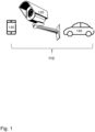
- Figure 1 depicts various exemplifying image-capturing devices 110.
- the image-capturing device 110 may e.g., be or comprise any of a camcorder, a network video recorder, a camera, a video camera 120 such as a surveillance camera or a monitoring camera, a digital camera, a wireless communication device 130, such as a smartphone, including an image sensor, or a car 140 including an image sensor.
- FIG. 2 depicts an exemplifying video network system 250 in which embodiments herein may be implemented.
- the video network system 250 may include an image-capturing device, such as the video camera 120, which can capture and perform image processing on a digital image 201, such as a digital video frame.
- a video server 260 in Figure 2 may obtain the video frame, for example from the video camera 120 over a network or the like, which is indicated in Figure 2 with the double-pointing arrows.
- the image-processing device may comprise or be the video server 260.
- the video server 260 is a computer-based device that is dedicated to delivering video.
- the video server 260 is connected over the video network system 250, to the image-capturing device, here exemplified by the video camera 120.
- the video server 260 may further be connected to a video storage 270 for storage of video frames, and/or connected to a monitor 280 for display of video frames.
- the video camera 120 is connected directly with the video storage 270 and/or the monitor 280, as indicated by the direct arrows between these devices in Figure 2 .
- the video camera 120 is connected to the video storage 270 and/or the monitor 280 via the video server 260, as indicated by the arrows between the video server 260 and the other devices.
- Figure 3 is a schematic view of an imaging system 300, in this case of a digital video camera, such as the video camera 120.
- the imaging system 300 images a scene on an image sensor 301.
- the image sensor 301 may be provided with a Bayer filter, such that different pixels will receive radiation of a particular wavelength region, in a known pattern.
- each pixel of the captured image is represented by one or more values representing the intensity of the captured light within a certain wavelength band. These values are usually referred to as colour components, or colour channels.
- image may refer to an image frame or video frame including information originating from an image sensor that has captured the image.
- the image signal processor 302 may comprise an image processing part 302a, sometimes referred to as an image processing pipeline, and a video post-processing part 302b.
- FIG. 3 illustrates a video stream 310 from the image sensor 301.
- the video stream 310 may comprise multiple captured video frames, such as a first captured video frame 311 and a second captured video frame 312.
- the stream of images may also be referred to as a video sequence.
- Image processing may comprise application of overlays (e.g., privacy masks, explanatory text).
- the image signal processor 302 may also be associated with an analytics engine performing object detection, recognition, alarms, etc.
- the image processing part 302a may e.g. perform image stabilization, apply noise filtering, distortion correction, global and/or local tone mapping, transformation, and flat-field correction.
- the video post-processing part 302b may for example crop parts of an image, apply overlays, and comprise the analytics engine. Thus, embodiments disclosed herein may be implemented by the video post-processing part 302b.
- the image may be forwarded to an encoder 303, wherein the information in the video frames is coded according to an encoding protocol, such as H.264.
- the encoded video frames are then forwarded to for example a receiving client, exemplified here with the monitor 280, to the video server 260, the storage 270, etc.
- an object of embodiments herein may be to improve detection of pixels representing reflections of detected objects in an image frame.
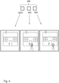
- FIG 4 illustrates a video sequence 400 corresponding to the video stream 310 of Figure 3 .
- the video sequence 400 comprises a plurality of image frames.
- the video sequence 400 comprises an image frame 402, which may also be referred to as a first image frame 402.
- the video sequence 400 further comprises a second image frame 403.
- the video sequence 400 may also comprise a background image frame 401b.
- the background image frame 401b may be derived from multiple image frames of the video sequence 400.
- the background image frame 401b is not necessarily part of the video sequence 400. Instead it may be stored on the image-processing device and retrieved when needed.
- the background image frame 401b may be derived from multiple image frames of the video sequence 400 by averaging the multiple image frames.
- the lower part of Figure 4 illustrates content of the background image frame 401b, the image frame 402 and the second image frame 403.
- the content of the background image frame 401b may comprise background objects such as a house.
- the background objects of the background image frame 401b are stationary such that they are also present at the same pixel locations in other image frames.
- the content of the image frame 402 and the second image frame 403 may comprise both background objects and foreground objects.
- the foreground objects may be moving in the scene and thus may be represented by different pixels in different image frames as illustrated by a moving person in Figure 4 .
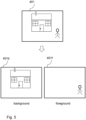
- Figure 5 illustrates a simplified method of obtaining the background image frame 401b from an image frame, such as an image frame 401, comprising a scene with different objects which may be classified as background objects and foreground objects according to some criteria.
- the background image frame 401b may be generated from the image frame 401 and may comprise the background objects of the image frame 401.
- a foreground image frame 401f may be generated and may comprise the foreground objects of the image frame 401.
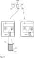
- Figure 6 is a schematic block diagram illustrating the reference method for masking objects in an image frame. More specifically, Figure 6 illustrates a part of an image frame captured by the video camera 120.
- the video camera 120 captures a scene with background and foreground objects. Specifically, an object 410 is captured and detected as a foreground object. If the object 410 has been detected as a person it may be masked in order to anonymize the person. As mentioned above one way to avoid identification of persons is by masking moving people and objects in images in real time. Masking in live and recorded video may be done by comparing a live camera view with a set background scene and applying dynamic masking to areas of change - essentially moving people and objects. Color masking, which may also be referred to solid color masking or monochrome masking where an object is masked by an overlaid solid mask of a certain color, provides privacy protection while enabling you to see movements. Mosaic masking, also referred to as pixelation, pixelated privacy masking or transparent pixelated masking shows moving objects in lower resolution and allows you to better distinguish forms by seeing an object's colors.
- a reflective surface in the scene such as a window illustrated in Figure 6
- An object of embodiments herein may therefore be to identify pixels in an image frame that represent surfaces in the scene that reflect the object 410 into the video camera 120 such that it is possible to apply image processing to the pixels representing those reflective surfaces.
- the reflections may, for example, be masked as well to provide improved anonymization.
- the video camera 120 captures the video sequence 400.
- the video sequence 400 captures a scene comprising background and foreground objects.
- one of the background objects is a house and one of the foreground objects is a person. Detected persons are to be masked.
- the background house comprises reflective surfaces, such as windows, which reflect the person into the video camera 120.
- an image of the person is present in the reflective surfaces.
- the background may for example comprise a first reflective surface 411 and a second reflective surface 412. In general, the reflective surface is part of a background object.
- the image frame 402 comprises pixels representing an image of the object 410 which is detected as a person, i.e., an object to be masked. However, the image frame 402 also comprises pixels representing an image of the first and second reflective surfaces 411, 412.
- Figure 7b represents the scene of Figure 7a captured with the second image frame 403, i.e., slightly after the first image frame 402.
- the object 410 has moved slightly with respect to the background. Also the image of the object 410 in the reflective surface 411 has moved.
- Figure 8 illustrates content of the first image frame 402 and content of the second image frame 403.
- the image-processing device 120, 260 may define the identified object 410 in the image frame 402 by a two-dimensional bounding box 413.
- the object 410 is illustrated as a rectangle for simplicity.
- the two-dimensional bounding box 413 may be defined by its coordinates in the image frame 402.
- a surface of the two-dimensional bounding box 413 may be divided into surface elements 414.
- Each surface element 414 of the two-dimensional bounding box 413 may be defined by its two-dimensional coordinate in the image frame 402 and by a colour value, such as a hue value. The colour value may be obtained by calculating an average colour value of pixels within the surface element 414.
- Embodiments herein are based on finding reflective surfaces that potentially may reflect the object into the camera 120 by tracing rays in a three-dimensional model of the scene.
- embodiments herein define a three-dimensional bounding box 415 of the defined object 410 in the three-dimensional model of the background scene, e.g., based on the defined object 410 in the image frame 402 an obtained position of the object 410 in the three-dimensional model and by extrapolating the defined object 410 in a plane extending along the normal of the image plane, i.e. along the depth plane of the image.
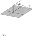
- Figure 9a illustrates a simplified three-dimensional model of the scene including the three-dimensional bounding box 415, the camera 120 and the reflective surface 411 of the background.
- the reflective surface 411 of the background is drawn as a two-dimensional sheet in Figure 9a for simplicity.
- the two-dimensional bounding box 413 and the surface elements 414 of the two-dimensional bounding box 413 may be used to extrapolate the defined object 410 in the depth plane.
- the three-dimensional bounding box 415 may be generated by extrapolating the two-dimensional bounding box 413.
- Surfaces of the three-dimensional bounding box 415 may be generated based on the surface elements 414 of the two-dimensional bounding box 413.
- Figure 9b schematically illustrates a part of the background model which comprises the first reflective surface 411.
- Figure 9b further schematically illustrates how a light ray from a back surface 416 of the three-dimensional bounding box 415 is reflected from the first reflective surface 411 into the camera 120.
- Figure 9b further schematically illustrates parts of the background image frame 401b, overlaid on the background model, which correspond to at least a part of the first reflective surface 411.
- the back surface 416 of the three-dimensional bounding box 415 may comprise surface elements 417 of the three-dimensional bounding box 415 which are copies of the surface elements 414 of the two-dimensional bounding box 413.
- Side surfaces of the three-dimensional bounding box 415 may be generated as copies of bounding surface elements 414 of the two-dimensional bounding box 413.
- a colour of the copied surface elements may be preserved.
- Figure 10 illustrates a flowchart describing a method performed in the image-processing device for detecting the reflection of the identified object 410 in the image frame 402 captured by the camera 120.
- the method may be performed by an image-processing device, such as the video camera 120 or the video server 260.
- the below actions may be taken in any suitable order, e.g., in another order than the order presented below.
- the background image frame 401b may be generated according to known methods. Background objects may be identified and defined in the background image frame 401b.
- the background image frame 401b does not comprise the foreground object 410.
- the image frame 402 may be obtained.
- the object 410 in the image frame 402 may be identified from image information in the image frame 402. For example, an object identification algorithm may be used to find objects in the scene.
- a three-dimensional model of the background scene of the image frame 401 is generated based on obtained three-dimensional information about the background scene.
- the background scene may for example be a room.
- the three-dimensional model of the background scene comprises spatial information about the background objects, such as position, size and orientation of surfaces of the background objects.
- the three-dimensional model of the background scene may comprise information about the direction of a normal of a surface of a background object. The normal may be used for ray tracing.
- the three-dimensional information about the background scene may comprise three-dimensional coordinates of surfaces in the background scene, a respective normal vector of the surfaces, three-dimensional coordinates of the camera 120 and an orientation of the camera 120.
- the three-dimensional model of the background scene may comprise information about a position of the camera 120 in relation to a position of the background object.
- the three-dimensional information about the background scene may be generated from Light Detection And Ranging (LIDAR).
- LIDAR Light Detection And Ranging
- the three-dimensional information about the background scene may be obtained by running a Neural Network with the background image frame 401b as input data.
- the three-dimensional model of the background scene is linked to the background image frame 401b.
- Mapping image data on top of for example LIDAR data is known in the art.
- the three-dimensional model of the background scene may be updated when the background image frame 401b is updated.
- the three-dimensional model of the background scene is modified by removing surfaces of the background objects which normal is directed towards the camera 120 since reflected light from these surfaces is not likely to reach the camera.
- the image-processing device 120, 260 defines the identified object 410 in the image frame 402 based on image information in the image frame 402.
- the image-processing device 120, 260 may define the identified object 410 in the image frame 402 by the two-dimensional bounding box 413. A position of the identified object 410 in the image frame 402 may be defined.
- the image-processing device 120, 260 defines the three-dimensional bounding box 415 of the defined object 410 in the three-dimensional model of the background scene.
- the three-dimensional bounding box 415 may be a cuboid.
- a bounding box may contain any shape and may simplify the computation. An arbitrary shape may fit inside the bounding box 415.
- the three-dimensional bounding box 415 comprises one or more voxels.
- the three-dimensional bounding box 415 may be based on the defined object 410 in the image frame 402, an obtained position of the object 410 in the three-dimensional model and by extrapolating the defined object 410 in a plane extending along the normal of the image plane.
- the plane extending along the normal of the image plane may also be referred to as the depth plane of the image.
- the image-processing device 120, 260 may extrapolate the object 410 by extrapolating bounding pixels of the object 410 from the captured image frame 402.
- pixels of the object 410 are extrapolated a certain distance in the plane of the normal of the image plane. For instance, a car has a fairly uniform length, which may be used to carry out the extension.
- the back surface 416 of the three-dimensional bounding box 415 may comprise pixels being copies of the pixels of the object 410 of the image frame 402, that is pixels within the two-dimensional bounding box 413.
- Side surfaces of the three-dimensional bounding box 415 may comprise pixels being copies of the pixels of the bounding pixels of the object 410 of the image frame 402. A colour of the copied pixels is preserved.
- the obtained position of the object 410 in the three-dimensional model may be obtained by three-dimensional detection of the object 410, such as based on LIDAR, RADAR, or depth estimation Artificial Intelligence (Al) based on the image information in the image frame 402.
- three-dimensional detection of the object 410 such as based on LIDAR, RADAR, or depth estimation Artificial Intelligence (Al) based on the image information in the image frame 402.
- the three-dimensional bounding box 415 is based directly on a three-dimensional mapping of the object 410, such as based on LIDAR, or depth estimation Artificial Intelligence (Al).
- the image-processing device 120, 260 defines surface elements 417 of the three-dimensional bounding box 415. Smaller surface elements 417 means better accuracy, but worse performance.
- a respective surface element 417 being defined by a centre coordinate 418 in the three-dimensional model of the background scene and a colour value.
- the colour value may be a hue value or a combination of Cb and Cr values in the YUV format. Other colour values are also possible.
- Hue is one of the main properties called colour appearance parameters of a colour, defined technically in the CIECAM02 model as "the degree to which a stimulus can be described as similar to or different from stimuli that are described as red, orange, yellow, green, blue, violet," within certain theories of colour vision.
- Hue may typically be represented quantitatively by a single number, often corresponding to an angular position around a central or neutral point or axis on a colour space coordinate diagram, such as a chromaticity diagram, or colour wheel.
- a respective surface element 417 of the three-dimensional bounding box 415 corresponds to multiple pixels from the captured image frame 402.
- the colour value of the respective surface element 417 is calculated as an average of colour values of the corresponding multiple pixels.
- the colour value of the surface element 417 may be defined by averaging colour values of pixels within another surface element from which the surface element 417 has been derived.
- the surface element 417 may be on the backside and may be derived from another surface element on the front side which is derived from a group of pixels of the image frame 402.
- the image-processing device 120, 260 determines a three-dimensional coordinate of the surface 411 in the three-dimensional model of the background scene which reflects light from the surface element 417 of the three-dimensional bounding box 415 of the object 410 into the camera 120. That is, the determined three-dimensional coordinate of the surface 411 in the three-dimensional model of the background scene is positioned such that light that comes from the surface element 417 and is reflected by the surface 411 at this three-dimensional coordinate will be captured by the camera 120.
- an actual lighting condition of the scene may determine whether or not it is possible to detect a reflection of the object 410 in pixels of the image frame 402 corresponding to the three-dimensional coordinate of the surface 411.
- action 1006 is about finding candidate reflective coordinates of the surface 411.
- the determined three-dimensional coordinate of the surface 411 in the three-dimensional model of the background scene may be stored.
- the determining is performed by tracing rays from the centre coordinate 418 of the surface element 417 of the three-dimensional bounding box 415 of the object 410 and based on a normal of the surface in the three-dimensional model of the background scene at said three-dimensional coordinate.
- the ray tracing may be repeated for multiple surface elements 417. For example, ray tracing may be performed from all surface elements of the three-dimensional bounding box 415. Then all corresponding three-dimensional coordinates of the surface 411 in the three-dimensional model of the background scene which reflect light from the surface elements 417 may be found.
- ray tracing is only performed for surface elements 417 that define the three-dimensional bounding box 415. In this way a contour of the projection of the three-dimensional bounding box 415 onto the surface 411 may be found and used later for determining which pixels of the image frame 402 to mask. This latter option requires less computations.
- Ray tracing may be performed by known methods.
- Ray tracing is a method for calculating the path of waves or particles through a system with regions of varying propagation velocity, absorption characteristics, and reflecting surfaces. Under these circumstances, wavefronts may bend, change direction, or reflect off surfaces.
- Ray tracing solves the problem by repeatedly advancing idealized narrow beams called rays through the medium by discrete amounts.
- Ray tracing works by assuming that the particle or wave can be modeled as a large number of very narrow beams (rays), and that there exists some distance, possibly very small, over which such a ray is locally straight.
- the ray tracer may advance the ray over this distance, and then use a local derivative of the medium to calculate the ray's new direction. From this location, a new ray is sent out and the process is repeated until a complete path is generated. If the simulation includes solid objects, the ray may be tested for intersection with them at each step, making adjustments to the ray's direction if a collision is found.
- the image-processing device 120, 260 identifies a first pixel 431 in the image frame 402 which corresponds to the determined three-dimensional coordinate of the surface 411.
- the identified first pixel may be a candidate reflection pixel.
- the image-processing device 120, 260 may identify multiple first pixels 431 in the image frame 402 which correspond to multiple determined three-dimensional coordinates of the surface 411.
- the image-processing device 120, 260 detects the reflection of the object 410 in the image frame 402 when a mixing of a first colour value of the identified first pixel 431 and the colour value of the surface element 417 of the object 410 and a ground truth colour value of the identified first pixel 431 fulfils a mixing criteria. That is, the identified first pixel 431 is detected as a pixel reflecting the object if mixing of a first colour value of the identified first pixel 431 and the colour value of the surface element 417 of the object 410 and a ground truth colour value of the identified first pixel 431 fulfils a mixing criteria.
- the mixing criteria may for example be that the colour value of the identified first pixel 431 of the background image frame 401b is roughly an addition of the colour value of the surface element 417 of the object 410 and the ground truth colour value. This may be checked by subtracting the ground truth colour value from the colour value of the identified first pixel 431 and comparing the obtained value with the colour value of the surface element 417 of the object 410.
- the ground truth colour value is a colour value of the identified first pixel 431 when there is no reflection from foreground objects.
- the ground truth colour value may be obtained from one or more background image frames 401b or from one or more neighbouring pixels to the identified first pixel 431 in the image frame 402.
- the ground truth colour value from the one or more background image frames 401b may be a value taken over time to produce an average value.
- the ground truth value may be stored in memory.
- the ground truth may be a heatmap that is built up over time. If some of the one or more background image frames 401b comprises the object 410 then the one or more background image frames 401b may be averaged to not contain any significant reflection of the object 410.
- Action 1008 may be repeated for multiple identified first pixels 431.
- Figure 11 illustrates a further flowchart describing a further method performed in the image-processing device for detecting the reflection of the identified object 410 in the image frame 402 captured by the camera 120.
- the method of Figure 11 is also for masking a pixel area that has been determined to represent a reflection of the object 410.
- the method of Figure 11 may be performed by the image-processing device, such as the video camera 120 or the video server 260.
- the below actions may be taken in any suitable order, e.g., in another order than the order presented below.
- the image-processing device may apply a mask to a pixel area 441 of the image frame 402.
- the pixel area 441 comprises the identified first pixel 431.
- the pixel area 441 is illustrated in Figure 9b .
- 260 detects the reflection of the object 410 in the image frame 402 when a mixing of the first colour value of the identified first pixel 431 and the colour value of the surface element 417 of the object 410 and the ground truth colour value of the identified first pixel 431 fulfils the mixing criteria.
- the identified first pixel 431 of the background image frame 401b is roughly an addition of the colour value of the surface element 417 of the object 410 and the ground truth colour value, then the identified first pixel 431 and surrounding pixels of the pixel area 441 may be masked.
- Figure 12 schematically illustrates the part of the background model which comprises the first reflective surface 411.
- Figure 12 further schematically illustrates parts of the background image frame 401b, overlaid on the background model, which correspond to at least the part of the first reflective surface 411.
- the masked pixel area 441 comprises all pixels corresponding to a projection 421 of the surface element 417 of the three-dimensional bounding box 415 onto the surface 411 or the second surface 412 in the three-dimensional model of the background scene.
- the masked pixel area 441 is limited to the pixels corresponding to the projection 421 of the surface element 417 of the three-dimensional bounding box 415 onto the surface 411 or the second surface 412. The projection is reflected into the camera 120.
- the projection 421 and an enlarged view of the projection 421 is also illustrated in Figure 12 .
- the enlarged view of the projection 421 has been illustrated as filled with pixels of the image frame 402 which correspond to the part of the surface 411 which is covered by the projection 421.
- the masked pixel area 441 may comprise the pixels of the image frame 402 which correspond to the part of the surface 411 which is covered by the projection 421.
- a method for corroborating the detection of the reflection of the identified object 410 in the image frame 402 will now be described with reference to Figure 11 and Figure 13 and may be performed by analysing whether or not the detected reflection moves between the first image frame 402 and at least a further image frame, such as the second image frame 403.
- the below method may be triggered when motion of the object 410 has been detected based on the second image frame 403 and the image frame 402.
- the image-processing device 120, 260 may increase a probability value of having found a reflection of the object 410 if both motion of the object 410 and motion of the reflection is detected.
- the image-processing device 120, 260 obtains the second image frame 403 of the video sequence 400 comprising the image frame 402.
- the second image frame 403 comprises the identified object 410.
- the second image frame 403 may be an image frame following directly after the first image frame 402 in the video sequence 400.
- the image-processing device 120, 260 defines the identified object 410 in the second image frame 403 based on image information in the second image frame 403.
- the image-processing device 120, 260 determines a respective second centre coordinate 420 of the surface element 417 of the three-dimensional bounding box 415 of the object 410 in the three-dimensional model of the background scene based on an obtained second position of the object 410 in the three-dimensional model.
- the second position of the object 410 in the three-dimensional model may be obtained in the same way as described above in relation to action 1004b.
- the second position of the object 410 in the three-dimensional model may correspond to a position of the object 410 in the second image frame 403.
- the image-processing device 120, 260 determines a second three-dimensional coordinate of the surface 411 or of the second surface 412 in the three-dimensional model of the background scene, which reflect light from the surface element 417 of the three-dimensional bounding box 415 of the object 410 into the camera 120 and differs from the determined three-dimensional coordinate of the surface 411.
- the determining is performed by tracing rays from the second centre coordinate 420 of the surface element 417 and based on a second normal of the surface 411 or of the second surface 412 in the three-dimensional model of the background scene at said second three-dimensional coordinate.
- the image-processing device 120, 260 identifies a second pixel 432 in the second image frame 403 which corresponds to the determined second three-dimensional coordinate of the surface or of the second surface 412.
- the image-processing device 120, 260 obtains a second colour value of the second pixel 432.
- the second colour value of the second pixel 432 may be stored.
- the image-processing device 120, 260 may confirm detection of the reflection of the object 410 when a mixing of the first colour value and the second colour value fulfils a second mixing criteria.
- next frame 403 look at the saved three-dimensional position from the previous frame 402, and compare the saved colour value to its current colour value. If there is a change roughly corresponding to the colour of the object 410, it is a strong indication that the reflection is moving. If this is concluded, it indicates that the area is reflective, which may increase a probability to add a mask.
- the image-processing device 120, 260 rejects detection of the reflection of the object 410 when the mixing of the first colour value and the second colour value does not fulfil the second mixing criteria.
- a colour value of the first pixel 431 in the second image frame 403 equals the first colour value.
- the image-processing device 120, 260 may apply a mask to a second pixel area 442 of the second image frame 403.
- the second pixel area 442 comprises the identified second pixel 432.
- the masked second pixel area 442 is limited to the pixels corresponding to a second projection of the surface element 417 of the three-dimensional bounding box 415 onto the surface 411 or the second surface 412.
- the image-processing device 120, 260 may determine to not apply a mask to the second pixel area 442 comprising the identified second pixel 432.
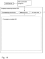
- the image-processing device 600 corresponds to any of the image-processing devices of Figure 1 or Figure 2 .
- the image-processing device 600 may comprise or be any of a camera, such as a surveillance camera, a monitoring camera, a camcorder, a network video recorder, and the wireless communication device 130.
- the image-processing device 600 may be the camera 120, such as a surveillance video camera, or the video-server 260.
- the image-processing device 600 is configured to perform the method according to Figure 10 or Figure 11 .
- the image-processing device 600 may further comprise a processing module 601, such as a means for performing the methods described herein.
- the means may be embodied in the form of one or more hardware modules and/or one or more software modules.
- the image-processing device 600 may further comprise a memory 602.
- the memory may comprise, such as contain or store, instructions, e.g. in the form of a computer program 603, which may comprise computer readable code units which when executed on the image-processing device 600 causes the image-processing device 600 to perform the methods described above, for example in relation to Figure 10 or Figure 11 .
- the image-processing device 600 may comprise a computer and then the computer readable code units may be executed on the computer and cause the computer to perform the method of Figure 10 or Figure 11 .
- the image-processing device 600 and/or the processing module 601 comprises a processing circuit 604 as an exemplifying hardware module, which may comprise one or more processors.
- the processing module 601 may be embodied in the form of, or 'realized by', the processing circuit 604.
- the instructions may be executable by the processing circuit 604, whereby the image-processing device 600 is operative to perform the methods of Figure 10 or Figure 11 as described above.
- the instructions when executed by the image-processing device 600 and/or the processing circuit 604, may cause the image-processing device 600 to perform the methods according to Figure 10 or Figure 11 .
- an image-processing device 600 for detecting the reflection of the identified object 410 in the image frame 402 captured by the camera 120.
- the memory 602 contains the instructions executable by said processing circuit 604 whereby the image-processing device 600 is operative for performing the method according to Figure 10 or Figure 11 .
- Figure 6 further illustrates a carrier 605, or program carrier, which comprises the computer program 603 as described directly above.
- the carrier 605 may be one of an electronic signal, an optical signal, a radio signal and a computer readable medium.
- the processing module 601 may comprise an Input/Output unit 606.
- the Input/Output unit 606 may comprise an image sensor configured for capturing the raw video frames described above such as the raw video frames comprised in the video stream 310 from the image sensor 301.
- the image-processing device 600 and/or the processing module 601 is configured to generate a three-dimensional model of a background scene of the image frame 402 based on obtained three-dimensional information about the background scene.
- the image-processing device 600 and/or the processing module 601 is further configured to define the identified object 410 in the image frame 402 based on image information in the image frame 402.
- the image-processing device 600 and/or the processing module 601 is further configured to define the identified object 410 in the image frame 402 based on image information in the image frame 402.
- the image-processing device 600 and/or the processing module 601 is further configured to define a three-dimensional bounding box 415 of the defined object 410 in the three-dimensional model of the background scene.
- the three-dimensional bounding box 415 may be based on the defined object 410 in the image frame 402, an obtained position of the object 410 in the three-dimensional model and by extrapolating the defined object 410 in a plane extending along the normal of the image plane.
- the image-processing device 600 and/or the processing module 601 is further configured to determine a three-dimensional coordinate of a surface 411 in the three-dimensional model of the background scene which reflects light from a surface element 416 of the three-dimensional bounding box 415 of the object 410 into the camera 120, wherein the determining is performed by tracing rays from the centre coordinate 418 of the surface element 416 of the three-dimensional bounding box 415 of the object 410 and based on a normal of the surface in the three-dimensional model of the background scene at said three-dimensional coordinate.
- the image-processing device 600 and/or the processing module 601 is further configured to identifying a first pixel 431 in the image frame 402 which corresponds to the determined three-dimensional coordinate of the surface 411.
- the image-processing device 600 and/or the processing module 601 is further configured to detecting the reflection of the object 410 in the image frame 402 when a mixing of a first colour value of the identified first pixel 431 and the colour value of the surface element 416 of the object 410 and a ground truth colour value of the identified first pixel 431 fulfils a mixing criteria.
- the image-processing device 600 and/or the processing module 601 is further configured to, in response to detecting the reflection of the object 410, apply a mask to a pixel area 441 of the image frame 402, the pixel area 441 comprising the identified first pixel 431.
- the image-processing device 600 and/or the processing module 601 is configured to obtain the second image frame 403 of the video sequence 400 comprising the image frame 402, the second image frame 403 comprising the identified object 410, and
- the image-processing device 600 and/or the processing module 601 is configured to, in response to confirming detection of the reflection of the object 410, apply a mask to a second pixel area 442 of the second image frame 403, the second pixel area 442 comprising the identified second pixel 432.
- the image-processing device 600 and/or the processing module 601 is configured to, in response to rejecting detection of the reflection of the object 410, determine to not apply a mask to the second pixel area 442 comprising the identified second pixel 432.
- the image-processing device 600 and/or the processing module 601 is configured to extrapolate the object 410 by being configured to extrapolate bounding pixels of the object 410 from the captured image frame 402.
- module may refer to one or more functional modules, each of which may be implemented as one or more hardware modules and/or one or more software modules and/or a combined software/hardware module.
- the module may represent a functional unit realized as software and/or hardware.
- the term "computer program carrier”, “program carrier”, or “carrier” may refer to one of an electronic signal, an optical signal, a radio signal, and a computer readable medium.
- the computer program carrier may exclude transitory, propagating signals, such as the electronic, optical and/or radio signal.
- the computer program carrier may be a non-transitory carrier, such as a non-transitory computer readable medium.
- processing module may include one or more hardware modules, one or more software modules or a combination thereof. Any such module, be it a hardware, software or a combined hardware-software module, may be a connecting means, providing means, configuring means, responding means, disabling means or the like as disclosed herein.
- the expression “means” may be a module corresponding to the modules listed above in conjunction with the figures.
- processing module or “processing circuit” may herein encompass a processing unit, comprising e.g. one or more processors, an Application Specific integrated Circuit (ASIC), a Field-Programmable Gate Array (FPGA) or the like.
- ASIC Application Specific integrated Circuit
- FPGA Field-Programmable Gate Array
- the processing circuit or the like may comprise one or more processor kernels.
- the expression “configured to/for” may mean that a processing circuit is configured to, such as adapted to or operative to, by means of software configuration and/or hardware configuration, perform one or more of the actions described herein.
- action may refer to an action, a step, an operation, a response, a reaction, an activity or the like. It shall be noted that an action herein may be split into two or more sub-actions as applicable. Moreover, also as applicable, it shall be noted that two or more of the actions described herein may be merged into a single action.
- memory may refer to a hard disk, a magnetic storage medium, a portable computer diskette or disc, flash memory, Random Access Memory (RAM) or the like. Furthermore, the term “memory” may refer to an internal register memory of a processor or the like.
- the term "computer readable medium” may be a Universal Serial Bus (USB) memory, a DVD-disc, a Blu-ray disc, a software module that is received as a stream of data, a Flash memory, a hard drive, a memory card, such as a MemoryStick, a Multimedia Card (MMC), Secure Digital (SD) card, etc.
- USB Universal Serial Bus
- MMC Multimedia Card
- SD Secure Digital
- One or more of the aforementioned examples of computer readable medium may be provided as one or more computer program products.
- computer readable code units may be text of a computer program, parts of or an entire binary file representing a computer program in a compiled format or anything there between.
- number and/or value may be any kind of number, such as binary, real, imaginary or rational number or the like. Moreover, “number” and/or “value” may be one or more characters, such as a letter or a string of letters. “Number” and/or “value” may also be represented by a string of bits, i.e. zeros and/or ones.
Landscapes
- Engineering & Computer Science (AREA)
- Physics & Mathematics (AREA)
- General Physics & Mathematics (AREA)
- Theoretical Computer Science (AREA)
- Multimedia (AREA)
- Computer Graphics (AREA)
- Software Systems (AREA)
- Computer Vision & Pattern Recognition (AREA)
- Geometry (AREA)
- Image Analysis (AREA)
Abstract
Description
- The embodiments herein relate to a method and an image-processing device for detecting a reflection of an identified object in an image frame. A corresponding computer program and a computer program carrier are also disclosed.
- Surveillance of the public using imaging, in particular video imaging, is common in many areas around the world. Areas that may need monitoring are for example banks, stores, and other areas where security is needed, such as schools and government facilities. Other areas that may need monitoring are processing, manufacturing and logistics applications where video surveillance is primarily used to monitor processes.
- However, there may be requirements to not be able to identify persons from the video surveillance. The requirement to not be able to identify persons may be in conflict with the requirement of being able to determine what is happening in the video. For example, it may be of interest to perform people counting or queue monitoring on anonymous image data. In practice, there is a trade-off between meeting these two requirements: non-identifiable video and extracting large amounts of data for different purposes such as people counting.
- Several image-processing techniques have been described to avoid identifying persons while still being able to recognize activities. For example, edge detection/representation, edge enhancement, silhouetting objects, and different sorts of "colour blurring", such as colour variation or dilation are such examples of manipulations. Privacy masking is another image-processing technique used in video surveillance to protect personal privacy by concealing parts of an image from view with a masked area.
- Image processing refers to any processing that is applied to an image. The processing can include application of various effects, masks, filters or the like, to the image. In this manner, the image can e.g. be sharpened, converted to grey scale, or altered in some way. The image has typically been captured by a video camera, a still image camera or the like.
- As mentioned above one way to avoid identification of persons is by masking moving people and objects in images in real time. Masking in live and recorded video can be done by comparing a live camera view with a set background scene and applying dynamic masking to areas of change - essentially moving people and objects. Color masking, which may also be referred to solid color masking or monochrome masking where an object is masked by an overlaid solid mask of a certain color, provides privacy protection while enabling you to see movements. Mosaic masking, also referred to as pixelation, pixelated privacy masking or transparent pixelated masking shows moving objects in lower resolution and allows you to better distinguish forms by seeing an object's colors.
- Masking live and recorded video is suitable for remote video monitoring or recording in areas where surveillance is otherwise problematic due to privacy rules and regulations. It's ideal for processing, manufacturing and logistics applications when video surveillance is primarily used to monitor processes. Other potential applications are in retail, education and at government facilities.
- Although masking techniques evolve there is still room for improvement. One problem that may arise is that reflective surfaces in a scene may reflect what is behind a privacy mask into a camera capturing the scene.
- This problem is especially tricky for dynamic masks, which are expected to move with the object.
- An object of embodiments herein may thus be to obviate some of the problems mentioned above, or at least reduce the impact of them. Specifically, an object of embodiments herein may be to identify pixels in an image that represent surfaces in the scene that reflect an object into a camera such that it is possible to apply image processing to the pixels representing those reflective surfaces. The reflections may, for example, be masked as well to provide improved anonymization.
- Embodiments herein solve the above problems by creating a three-dimensional representation of a scene captured by an image frame from a camera, including an identified masked object, and tracing optical rays in the three-dimensional representation of the scene from the identified object to the camera via reflecting surfaces in the scene. However, only those reflecting surfaces that are sufficiently similar to the actual object itself will be detected as reflecting the object. Specifically, only those reflecting surfaces that produce a reflection which colour value matches a colour value of the object being reflected will be detected. Comparison of the colour value is performed by mixing colour values of pixels of the image frame representing the object, the reflecting surface and pixels of a background image frame representing the reflecting surface without influence from the object.
- According to an aspect, the object is achieved by a method, performed by an image-processing device for detecting a reflection of an identified object in an image frame captured by a camera. The method comprises generating a three-dimensional model of a background scene of the image frame based on obtained three-dimensional information about the background scene.
- The method further comprises defining the identified object in the image frame based on image information in the image frame.
- The method further comprises defining a three-dimensional bounding box of the defined object in the three-dimensional model of the background scene.
- The method further comprises defining surface elements of the three-dimensional bounding box, a respective surface element being defined by a centre coordinate in the three-dimensional model of the background scene and a colour value.
- The method further comprises determining a three-dimensional coordinate of a surface in the three-dimensional model of the background scene which reflects light from a surface element of the three-dimensional bounding box of the object into the camera, wherein the determining is performed by tracing rays from the centre coordinate of the surface element of the three-dimensional bounding box of the object and based on a normal of the surface in the three-dimensional model of the background scene at said three-dimensional coordinate.
- The method further comprises identifying a first pixel in the image frame which corresponds to the determined three-dimensional coordinate of the surface.
- The method further comprises detecting the reflection of the object when a mixing of a first colour value of the identified first pixel and a colour value of the surface element of the object and a ground truth colour value of the identified first pixel fulfils a mixing criteria.
- The ground truth represents the reflecting surface without influence from the object. The ground truth colour value may be obtained from one or more background image frames or from one or more neighbouring pixels to the identified first pixel in the image frame.
- According to another aspect, the object is achieved by an image-processing device configured to perform the above method.
- According to further aspects, the object is achieved by a computer program and a computer program carrier corresponding to the aspects above.
- Embodiments herein find candidate reflective pixels in an image frame by ray tracing optical rays from the object to the camera in the three-dimensional model of the scene captured in the image frame and corroborate detection of reflective pixels by comparing colour values of pixels of the object and pixels of the reflecting surface. A ground truth value of the reflecting pixels is also used to achieve an unbiased result.
- Thus, the image-processing device will only detect reflecting pixels that are similar enough to the object.
- The various aspects of embodiments disclosed herein, including particular features and advantages thereof, will be readily understood from the following detailed description and the accompanying drawings, in which:
-
Figure 1 illustrates exemplifying embodiments of image-capturing devices, -
Figure 2 illustrates exemplifying embodiments of a video network system, -
Figure 3 is a schematic block diagram illustrating an exemplifying embodiment of an imaging system, -
Figure 4 is a schematic block diagram illustrating a stream of image frames and their content, -
Figure 5 is a schematic block diagram illustrating embodiments of a method in the image-processing device, -
Figure 6 is a schematic block diagram illustrating a reference method for masking objects in an image frame, -
Figure 7a is a schematic block diagram illustrating a first scenario in which embodiments disclosed herein may be implemented, -
Figure 7b is a schematic block diagram illustrating a second scenario in which embodiments disclosed herein may be implemented, -
Figure 8 is a schematic block diagram illustrating embodiments of a method in the image-processing device, -
Figure 9a is a schematic block diagram illustrating embodiments of a method in the image-processing device, -
Figure 9b is a schematic block diagram illustrating embodiments of a method in the image-processing device, -
Figure 10 is a flowchart illustrating embodiments of a method in an image-processing device, -
Figure 11 is a flowchart illustrating embodiments of a method in an image-processing device, -
Figure 12 is a schematic block diagram illustrating further embodiments of a method in the image-processing device, -
Figure 13 is a schematic block diagram illustrating further embodiments of a method in the image-processing device, -
Figure 14 is a schematic block diagram illustrating embodiments of the image-processing device. - Embodiments disclosed herein are directed to improving detection of pixels representing reflections of detected objects in an image frame, such as an image frame in a video stream.
- Specifically, embodiments disclosed herein are directed to improving anonymization of image frames.
- Thus, embodiments herein may be implemented in an image-processing device. In some embodiments herein the image-processing device may comprise or be an image-capturing device such as a digital camera.
Figure 1 depicts various exemplifying image-capturingdevices 110. The image-capturingdevice 110 may e.g., be or comprise any of a camcorder, a network video recorder, a camera, avideo camera 120 such as a surveillance camera or a monitoring camera, a digital camera, awireless communication device 130, such as a smartphone, including an image sensor, or acar 140 including an image sensor. -
Figure 2 depicts an exemplifyingvideo network system 250 in which embodiments herein may be implemented. Thevideo network system 250 may include an image-capturing device, such as thevideo camera 120, which can capture and perform image processing on adigital image 201, such as a digital video frame. Avideo server 260 inFigure 2 may obtain the video frame, for example from thevideo camera 120 over a network or the like, which is indicated inFigure 2 with the double-pointing arrows. In some embodiments herein the image-processing device may comprise or be thevideo server 260. - The
video server 260 is a computer-based device that is dedicated to delivering video. - However, in
Figure 2 , thevideo server 260 is connected over thevideo network system 250, to the image-capturing device, here exemplified by thevideo camera 120. Thevideo server 260 may further be connected to avideo storage 270 for storage of video frames, and/or connected to amonitor 280 for display of video frames. In some embodiments thevideo camera 120 is connected directly with thevideo storage 270 and/or themonitor 280, as indicated by the direct arrows between these devices inFigure 2 . In some other embodiments thevideo camera 120 is connected to thevideo storage 270 and/or themonitor 280 via thevideo server 260, as indicated by the arrows between thevideo server 260 and the other devices. -
Figure 3 is a schematic view of animaging system 300, in this case of a digital video camera, such as thevideo camera 120. Theimaging system 300 images a scene on animage sensor 301. Theimage sensor 301 may be provided with a Bayer filter, such that different pixels will receive radiation of a particular wavelength region, in a known pattern. Typically, each pixel of the captured image is represented by one or more values representing the intensity of the captured light within a certain wavelength band. These values are usually referred to as colour components, or colour channels. The term "image" may refer to an image frame or video frame including information originating from an image sensor that has captured the image. - After having read the signal of individual sensor pixels of the
image sensors 301, different image processing actions may be performed by animage signal processor 302. Theimage signal processor 302 may comprise animage processing part 302a, sometimes referred to as an image processing pipeline, and a videopost-processing part 302b. - Typically for video processing the images are comprised in a stream of images, also referred to as a stream of video frames.
Figure 3 illustrates avideo stream 310 from theimage sensor 301. Thevideo stream 310 may comprise multiple captured video frames, such as a first capturedvideo frame 311 and a second capturedvideo frame 312. The stream of images may also be referred to as a video sequence. - Image processing may comprise application of overlays (e.g., privacy masks, explanatory text). The
image signal processor 302 may also be associated with an analytics engine performing object detection, recognition, alarms, etc. - The
image processing part 302a may e.g. perform image stabilization, apply noise filtering, distortion correction, global and/or local tone mapping, transformation, and flat-field correction. The videopost-processing part 302b may for example crop parts of an image, apply overlays, and comprise the analytics engine. Thus, embodiments disclosed herein may be implemented by the videopost-processing part 302b. - Following the
image signal processor 302 the image may be forwarded to anencoder 303, wherein the information in the video frames is coded according to an encoding protocol, such as H.264. The encoded video frames are then forwarded to for example a receiving client, exemplified here with themonitor 280, to thevideo server 260, thestorage 270, etc. - As mentioned above, an object of embodiments herein may be to improve detection of pixels representing reflections of detected objects in an image frame.
-
Figure 4 illustrates avideo sequence 400 corresponding to thevideo stream 310 ofFigure 3 . Thevideo sequence 400 comprises a plurality of image frames. For example, thevideo sequence 400 comprises animage frame 402, which may also be referred to as afirst image frame 402. Thevideo sequence 400 further comprises asecond image frame 403. Thevideo sequence 400 may also comprise abackground image frame 401b. In some embodiments herein thebackground image frame 401b may be derived from multiple image frames of thevideo sequence 400. Then thebackground image frame 401b is not necessarily part of thevideo sequence 400. Instead it may be stored on the image-processing device and retrieved when needed. Thebackground image frame 401b may be derived from multiple image frames of thevideo sequence 400 by averaging the multiple image frames. - The lower part of
Figure 4 illustrates content of thebackground image frame 401b, theimage frame 402 and thesecond image frame 403. The content of thebackground image frame 401b may comprise background objects such as a house. Preferably the background objects of thebackground image frame 401b are stationary such that they are also present at the same pixel locations in other image frames. The content of theimage frame 402 and thesecond image frame 403 may comprise both background objects and foreground objects. The foreground objects may be moving in the scene and thus may be represented by different pixels in different image frames as illustrated by a moving person inFigure 4 . -
Figure 5 illustrates a simplified method of obtaining thebackground image frame 401b from an image frame, such as animage frame 401, comprising a scene with different objects which may be classified as background objects and foreground objects according to some criteria. Thebackground image frame 401b may be generated from theimage frame 401 and may comprise the background objects of theimage frame 401. Correspondingly, aforeground image frame 401f may be generated and may comprise the foreground objects of theimage frame 401. - To appreciate the advantages of embodiments disclosed herein a reference method will first be described.
Figure 6 is a schematic block diagram illustrating the reference method for masking objects in an image frame. More specifically,Figure 6 illustrates a part of an image frame captured by thevideo camera 120. - The
video camera 120 captures a scene with background and foreground objects. Specifically, anobject 410 is captured and detected as a foreground object. If theobject 410 has been detected as a person it may be masked in order to anonymize the person. As mentioned above one way to avoid identification of persons is by masking moving people and objects in images in real time. Masking in live and recorded video may be done by comparing a live camera view with a set background scene and applying dynamic masking to areas of change - essentially moving people and objects. Color masking, which may also be referred to solid color masking or monochrome masking where an object is masked by an overlaid solid mask of a certain color, provides privacy protection while enabling you to see movements. Mosaic masking, also referred to as pixelation, pixelated privacy masking or transparent pixelated masking shows moving objects in lower resolution and allows you to better distinguish forms by seeing an object's colors. - However, one problem that may arise is that a reflective surface in the scene, such as a window illustrated in
Figure 6 , may reflect what is behind a privacy mask into thevideo camera 120 capturing the scene. - An object of embodiments herein may therefore be to identify pixels in an image frame that represent surfaces in the scene that reflect the
object 410 into thevideo camera 120 such that it is possible to apply image processing to the pixels representing those reflective surfaces. The reflections may, for example, be masked as well to provide improved anonymization. - Exemplifying embodiments for detecting a reflection of the identified
object 410 in theimage frame 402 captured by thecamera 120, will now be described with reference toFigure 7a ,Figure 7b ,Figure 8 ,Figure 9a ,Figure 9b , Figure 9c, Figure 9d and Figure 9e, and with further reference toFigures 2 ,3 and4 . - In a scenario in which embodiments herein may be implemented the
video camera 120 captures thevideo sequence 400. Thevideo sequence 400 captures a scene comprising background and foreground objects. In the case ofFigure 7a , illustrating a part of an image frame of thevideo sequence 400, one of the background objects is a house and one of the foreground objects is a person. Detected persons are to be masked. However, the background house comprises reflective surfaces, such as windows, which reflect the person into thevideo camera 120. Thus, an image of the person is present in the reflective surfaces. The background may for example comprise a firstreflective surface 411 and a secondreflective surface 412. In general, the reflective surface is part of a background object. - The
image frame 402 comprises pixels representing an image of theobject 410 which is detected as a person, i.e., an object to be masked. However, theimage frame 402 also comprises pixels representing an image of the first and secondreflective surfaces -
Figure 7b represents the scene ofFigure 7a captured with thesecond image frame 403, i.e., slightly after thefirst image frame 402. InFigure 7b theobject 410 has moved slightly with respect to the background. Also the image of theobject 410 in thereflective surface 411 has moved. -
Figure 8 illustrates content of thefirst image frame 402 and content of thesecond image frame 403. The image-processingdevice object 410 in theimage frame 402 by a two-dimensional bounding box 413. InFigure 8 theobject 410 is illustrated as a rectangle for simplicity. The two-dimensional bounding box 413 may be defined by its coordinates in theimage frame 402. Further, a surface of the two-dimensional bounding box 413 may be divided intosurface elements 414. Eachsurface element 414 of the two-dimensional bounding box 413 may be defined by its two-dimensional coordinate in theimage frame 402 and by a colour value, such as a hue value. The colour value may be obtained by calculating an average colour value of pixels within thesurface element 414. - Embodiments herein are based on finding reflective surfaces that potentially may reflect the object into the
camera 120 by tracing rays in a three-dimensional model of the scene. To do so embodiments herein define a three-dimensional bounding box 415 of the definedobject 410 in the three-dimensional model of the background scene, e.g., based on the definedobject 410 in theimage frame 402 an obtained position of theobject 410 in the three-dimensional model and by extrapolating the definedobject 410 in a plane extending along the normal of the image plane, i.e. along the depth plane of the image. -
Figure 9a illustrates a simplified three-dimensional model of the scene including the three-dimensional bounding box 415, thecamera 120 and thereflective surface 411 of the background. Thereflective surface 411 of the background is drawn as a two-dimensional sheet inFigure 9a for simplicity. - The two-
dimensional bounding box 413 and thesurface elements 414 of the two-dimensional bounding box 413 may be used to extrapolate the definedobject 410 in the depth plane. For example, the three-dimensional bounding box 415 may be generated by extrapolating the two-dimensional bounding box 413. Surfaces of the three-dimensional bounding box 415 may be generated based on thesurface elements 414 of the two-dimensional bounding box 413. -
Figure 9b schematically illustrates a part of the background model which comprises the firstreflective surface 411.Figure 9b further schematically illustrates how a light ray from aback surface 416 of the three-dimensional bounding box 415 is reflected from the firstreflective surface 411 into thecamera 120.Figure 9b further schematically illustrates parts of thebackground image frame 401b, overlaid on the background model, which correspond to at least a part of the firstreflective surface 411. Theback surface 416 of the three-dimensional bounding box 415 may comprisesurface elements 417 of the three-dimensional bounding box 415 which are copies of thesurface elements 414 of the two-dimensional bounding box 413. Side surfaces of the three-dimensional bounding box 415 may be generated as copies of boundingsurface elements 414 of the two-dimensional bounding box 413. A colour of the copied surface elements may be preserved. -
Figure 10 illustrates a flowchart describing a method performed in the image-processing device for detecting the reflection of the identifiedobject 410 in theimage frame 402 captured by thecamera 120. - The method may be performed by an image-processing device, such as the
video camera 120 or thevideo server 260. - The below actions may be taken in any suitable order, e.g., in another order than the order presented below.
- The
background image frame 401b may be generated according to known methods. Background objects may be identified and defined in thebackground image frame 401b. - Preferably, the
background image frame 401b does not comprise theforeground object 410. - The
image frame 402 may be obtained. Theobject 410 in theimage frame 402 may be identified from image information in theimage frame 402. For example, an object identification algorithm may be used to find objects in the scene. - A three-dimensional model of the background scene of the
image frame 401 is generated based on obtained three-dimensional information about the background scene. The background scene may for example be a room. - The three-dimensional model of the background scene comprises spatial information about the background objects, such as position, size and orientation of surfaces of the background objects. For example, the three-dimensional model of the background scene may comprise information about the direction of a normal of a surface of a background object. The normal may be used for ray tracing.
- The three-dimensional information about the background scene may comprise three-dimensional coordinates of surfaces in the background scene, a respective normal vector of the surfaces, three-dimensional coordinates of the
camera 120 and an orientation of thecamera 120. For example, the three-dimensional model of the background scene may comprise information about a position of thecamera 120 in relation to a position of the background object. - The three-dimensional information about the background scene may be generated from Light Detection And Ranging (LIDAR).
- In some other embodiments the three-dimensional information about the background scene may be obtained by running a Neural Network with the
background image frame 401b as input data. - The three-dimensional model of the background scene is linked to the
background image frame 401b. For example, there is a mapping between three-dimensional coordinates of the surfaces of the background model and the corresponding pixels of thebackground image frame 401b. Mapping image data on top of for example LIDAR data is known in the art. - The three-dimensional model of the background scene may be updated when the
background image frame 401b is updated. - In some embodiments herein the three-dimensional model of the background scene is modified by removing surfaces of the background objects which normal is directed towards the
camera 120 since reflected light from these surfaces is not likely to reach the camera. - The image-processing
device object 410 in theimage frame 402 based on image information in theimage frame 402. - For example, the image-processing
device object 410 in theimage frame 402 by the two-dimensional bounding box 413. A position of the identifiedobject 410 in theimage frame 402 may be defined. - The image-processing
device dimensional bounding box 415 of the definedobject 410 in the three-dimensional model of the background scene. The three-dimensional bounding box 415 may be a cuboid. A bounding box may contain any shape and may simplify the computation. An arbitrary shape may fit inside thebounding box 415. In some embodiments herein the three-dimensional bounding box 415 comprises one or more voxels. The three-dimensional bounding box 415 may be based on the definedobject 410 in theimage frame 402, an obtained position of theobject 410 in the three-dimensional model and by extrapolating the definedobject 410 in a plane extending along the normal of the image plane. The plane extending along the normal of the image plane may also be referred to as the depth plane of the image. - The image-processing
device object 410 by extrapolating bounding pixels of theobject 410 from the capturedimage frame 402. - In some example embodiments pixels of the
object 410 are extrapolated a certain distance in the plane of the normal of the image plane. For instance, a car has a fairly uniform length, which may be used to carry out the extension. - The
back surface 416 of the three-dimensional bounding box 415 may comprise pixels being copies of the pixels of theobject 410 of theimage frame 402, that is pixels within the two-dimensional bounding box 413. Side surfaces of the three-dimensional bounding box 415 may comprise pixels being copies of the pixels of the bounding pixels of theobject 410 of theimage frame 402. A colour of the copied pixels is preserved. - The obtained position of the
object 410 in the three-dimensional model may be obtained by three-dimensional detection of theobject 410, such as based on LIDAR, RADAR, or depth estimation Artificial Intelligence (Al) based on the image information in theimage frame 402. - In some other embodiments the three-
dimensional bounding box 415 is based directly on a three-dimensional mapping of theobject 410, such as based on LIDAR, or depth estimation Artificial Intelligence (Al). - The image-processing
device surface elements 417 of the three-dimensional bounding box 415.Smaller surface elements 417 means better accuracy, but worse performance. - A
respective surface element 417 being defined by a centre coordinate 418 in the three-dimensional model of the background scene and a colour value. - The colour value may be a hue value or a combination of Cb and Cr values in the YUV format. Other colour values are also possible.
- Hue is one of the main properties called colour appearance parameters of a colour, defined technically in the CIECAM02 model as "the degree to which a stimulus can be described as similar to or different from stimuli that are described as red, orange, yellow, green, blue, violet," within certain theories of colour vision. Hue may typically be represented quantitatively by a single number, often corresponding to an angular position around a central or neutral point or axis on a colour space coordinate diagram, such as a chromaticity diagram, or colour wheel.
- A
respective surface element 417 of the three-dimensional bounding box 415 corresponds to multiple pixels from the capturedimage frame 402. The colour value of therespective surface element 417 is calculated as an average of colour values of the corresponding multiple pixels. - The colour value of the
surface element 417 may be defined by averaging colour values of pixels within another surface element from which thesurface element 417 has been derived. For example, thesurface element 417 may be on the backside and may be derived from another surface element on the front side which is derived from a group of pixels of theimage frame 402. - The image-processing
device surface 411 in the three-dimensional model of the background scene which reflects light from thesurface element 417 of the three-dimensional bounding box 415 of theobject 410 into thecamera 120. That is, the determined three-dimensional coordinate of thesurface 411 in the three-dimensional model of the background scene is positioned such that light that comes from thesurface element 417 and is reflected by thesurface 411 at this three-dimensional coordinate will be captured by thecamera 120. However, an actual lighting condition of the scene may determine whether or not it is possible to detect a reflection of theobject 410 in pixels of theimage frame 402 corresponding to the three-dimensional coordinate of thesurface 411. Thus,action 1006 is about finding candidate reflective coordinates of thesurface 411. - The determined three-dimensional coordinate of the
surface 411 in the three-dimensional model of the background scene may be stored. - The determining is performed by tracing rays from the centre coordinate 418 of the
surface element 417 of the three-dimensional bounding box 415 of theobject 410 and based on a normal of the surface in the three-dimensional model of the background scene at said three-dimensional coordinate. - The ray tracing may be repeated for
multiple surface elements 417. For example, ray tracing may be performed from all surface elements of the three-dimensional bounding box 415. Then all corresponding three-dimensional coordinates of thesurface 411 in the three-dimensional model of the background scene which reflect light from thesurface elements 417 may be found. - In some other embodiments ray tracing is only performed for
surface elements 417 that define the three-dimensional bounding box 415. In this way a contour of the projection of the three-dimensional bounding box 415 onto thesurface 411 may be found and used later for determining which pixels of theimage frame 402 to mask. This latter option requires less computations. - Ray tracing may be performed by known methods. Ray tracing is a method for calculating the path of waves or particles through a system with regions of varying propagation velocity, absorption characteristics, and reflecting surfaces. Under these circumstances, wavefronts may bend, change direction, or reflect off surfaces. Ray tracing solves the problem by repeatedly advancing idealized narrow beams called rays through the medium by discrete amounts.
- When applied to problems of electromagnetic radiation, such as light, ray tracing often relies on approximate solutions to Maxwell's equations that are valid as long as the light waves propagate through and around objects whose dimensions are much greater than the light's wavelength.
- Ray tracing works by assuming that the particle or wave can be modeled as a large number of very narrow beams (rays), and that there exists some distance, possibly very small, over which such a ray is locally straight. The ray tracer may advance the ray over this distance, and then use a local derivative of the medium to calculate the ray's new direction. From this location, a new ray is sent out and the process is repeated until a complete path is generated. If the simulation includes solid objects, the ray may be tested for intersection with them at each step, making adjustments to the ray's direction if a collision is found.
- The image-processing
device first pixel 431 in theimage frame 402 which corresponds to the determined three-dimensional coordinate of thesurface 411. The identified first pixel may be a candidate reflection pixel. - The image-processing
device first pixels 431 in theimage frame 402 which correspond to multiple determined three-dimensional coordinates of thesurface 411. - The image-processing
device object 410 in theimage frame 402 when a mixing of a first colour value of the identifiedfirst pixel 431 and the colour value of thesurface element 417 of theobject 410 and a ground truth colour value of the identifiedfirst pixel 431 fulfils a mixing criteria. That is, the identifiedfirst pixel 431 is detected as a pixel reflecting the object if mixing of a first colour value of the identifiedfirst pixel 431 and the colour value of thesurface element 417 of theobject 410 and a ground truth colour value of the identifiedfirst pixel 431 fulfils a mixing criteria. The mixing criteria may for example be that the colour value of the identifiedfirst pixel 431 of thebackground image frame 401b is roughly an addition of the colour value of thesurface element 417 of theobject 410 and the ground truth colour value. This may be checked by subtracting the ground truth colour value from the colour value of the identifiedfirst pixel 431 and comparing the obtained value with the colour value of thesurface element 417 of theobject 410. - The ground truth colour value is a colour value of the identified
first pixel 431 when there is no reflection from foreground objects. - The ground truth colour value may be obtained from one or more background image frames 401b or from one or more neighbouring pixels to the identified
first pixel 431 in theimage frame 402. - The ground truth colour value from the one or more background image frames 401b may be a value taken over time to produce an average value. The ground truth value may be stored in memory.
- The ground truth may be a heatmap that is built up over time. If some of the one or more background image frames 401b comprises the
object 410 then the one or more background image frames 401b may be averaged to not contain any significant reflection of theobject 410. -
Action 1008 may be repeated for multiple identifiedfirst pixels 431. -
Figure 11 illustrates a further flowchart describing a further method performed in the image-processing device for detecting the reflection of the identifiedobject 410 in theimage frame 402 captured by thecamera 120. The method ofFigure 11 is also for masking a pixel area that has been determined to represent a reflection of theobject 410. - The method of
Figure 11 may be performed by the image-processing device, such as thevideo camera 120 or thevideo server 260. - The below actions may be taken in any suitable order, e.g., in another order than the order presented below.
- In response to detecting the reflection of the
object 410 the image-processing device may apply a mask to apixel area 441 of theimage frame 402. Thepixel area 441 comprises the identifiedfirst pixel 431. Thepixel area 441 is illustrated inFigure 9b . As mentioned above in relation toaction 1008 image-processingdevice object 410 in theimage frame 402 when a mixing of the first colour value of the identifiedfirst pixel 431 and the colour value of thesurface element 417 of theobject 410 and the ground truth colour value of the identifiedfirst pixel 431 fulfils the mixing criteria. For example, if the colour value of the identifiedfirst pixel 431 of thebackground image frame 401b is roughly an addition of the colour value of thesurface element 417 of theobject 410 and the ground truth colour value, then the identifiedfirst pixel 431 and surrounding pixels of thepixel area 441 may be masked. -
Figure 12 schematically illustrates the part of the background model which comprises the firstreflective surface 411.Figure 12 further schematically illustrates parts of thebackground image frame 401b, overlaid on the background model, which correspond to at least the part of the firstreflective surface 411. In some embodiments herein themasked pixel area 441 comprises all pixels corresponding to aprojection 421 of thesurface element 417 of the three-dimensional bounding box 415 onto thesurface 411 or thesecond surface 412 in the three-dimensional model of the background scene. In some embodiments herein themasked pixel area 441 is limited to the pixels corresponding to theprojection 421 of thesurface element 417 of the three-dimensional bounding box 415 onto thesurface 411 or thesecond surface 412. The projection is reflected into thecamera 120. Theprojection 421 and an enlarged view of theprojection 421 is also illustrated inFigure 12 . The enlarged view of theprojection 421 has been illustrated as filled with pixels of theimage frame 402 which correspond to the part of thesurface 411 which is covered by theprojection 421. Thus, themasked pixel area 441 may comprise the pixels of theimage frame 402 which correspond to the part of thesurface 411 which is covered by theprojection 421. - A method for corroborating the detection of the reflection of the identified
object 410 in theimage frame 402 will now be described with reference toFigure 11 andFigure 13 and may be performed by analysing whether or not the detected reflection moves between thefirst image frame 402 and at least a further image frame, such as thesecond image frame 403. - The below method may be triggered when motion of the
object 410 has been detected based on thesecond image frame 403 and theimage frame 402. - The image-processing
device object 410 if both motion of theobject 410 and motion of the reflection is detected. - In some embodiments herein the image-processing
device second image frame 403 of thevideo sequence 400 comprising theimage frame 402. Thesecond image frame 403 comprises the identifiedobject 410. Thesecond image frame 403 may be an image frame following directly after thefirst image frame 402 in thevideo sequence 400. - The image-processing
device object 410 in thesecond image frame 403 based on image information in thesecond image frame 403. - The image-processing
device surface element 417 of the three-dimensional bounding box 415 of theobject 410 in the three-dimensional model of the background scene based on an obtained second position of theobject 410 in the three-dimensional model. The second position of theobject 410 in the three-dimensional model may be obtained in the same way as described above in relation toaction 1004b. The second position of theobject 410 in the three-dimensional model may correspond to a position of theobject 410 in thesecond image frame 403. - The image-processing
device surface 411 or of thesecond surface 412 in the three-dimensional model of the background scene, which reflect light from thesurface element 417 of the three-dimensional bounding box 415 of theobject 410 into thecamera 120 and differs from the determined three-dimensional coordinate of thesurface 411. - The determining is performed by tracing rays from the second centre coordinate 420 of the
surface element 417 and based on a second normal of thesurface 411 or of thesecond surface 412 in the three-dimensional model of the background scene at said second three-dimensional coordinate. - The image-processing
device second pixel 432 in thesecond image frame 403 which corresponds to the determined second three-dimensional coordinate of the surface or of thesecond surface 412. - The image-processing
device second pixel 432. The second colour value of thesecond pixel 432 may be stored. - The image-processing
device object 410 when a mixing of the first colour value and the second colour value fulfils a second mixing criteria. - For example, for the
next frame 403 look at the saved three-dimensional position from theprevious frame 402, and compare the saved colour value to its current colour value. If there is a change roughly corresponding to the colour of theobject 410, it is a strong indication that the reflection is moving. If this is concluded, it indicates that the area is reflective, which may increase a probability to add a mask. - In some other embodiments herein the image-processing
device object 410 when the mixing of the first colour value and the second colour value does not fulfil the second mixing criteria. A colour value of thefirst pixel 431 in thesecond image frame 403 equals the first colour value. - Thus, if the second colour value is different from the first colour value, but the colour value of the pixel area that was analysed for the
previous frame 402 is the same, this indicates a false positive. - This means that the object is moving, but there is not a moving reflection. If the object is moving, but the reflection is not, this indicates a false positive and removal of the reflective mask at this area may be considered.
- In response to confirming detection of the reflection of the
object 410, the image-processingdevice second pixel area 442 of thesecond image frame 403. Thesecond pixel area 442 comprises the identifiedsecond pixel 432. In some embodiments herein the maskedsecond pixel area 442 is limited to the pixels corresponding to a second projection of thesurface element 417 of the three-dimensional bounding box 415 onto thesurface 411 or thesecond surface 412. - In response to rejecting detection of the reflection of the
object 410, the image-processingdevice second pixel area 442 comprising the identifiedsecond pixel 432. - With reference to
Figure 14 , a schematic block diagram of embodiments of an image-processingdevice 600 is shown. The image-processingdevice 600 corresponds to any of the image-processing devices ofFigure 1 orFigure 2 . Thus, the image-processingdevice 600 may comprise or be any of a camera, such as a surveillance camera, a monitoring camera, a camcorder, a network video recorder, and thewireless communication device 130. In particular, the image-processingdevice 600 may be thecamera 120, such as a surveillance video camera, or the video-server 260. - As mentioned above, the image-processing
device 600 is configured to perform the method according toFigure 10 orFigure 11 . - The image-processing
device 600 may further comprise aprocessing module 601, such as a means for performing the methods described herein. The means may be embodied in the form of one or more hardware modules and/or one or more software modules. - The image-processing
device 600 may further comprise amemory 602. The memory may comprise, such as contain or store, instructions, e.g. in the form of acomputer program 603, which may comprise computer readable code units which when executed on the image-processingdevice 600 causes the image-processingdevice 600 to perform the methods described above, for example in relation toFigure 10 orFigure 11 . - The image-processing
device 600 may comprise a computer and then the computer readable code units may be executed on the computer and cause the computer to perform the method ofFigure 10 orFigure 11 . - According to some embodiments herein, the image-processing
device 600 and/or theprocessing module 601 comprises aprocessing circuit 604 as an exemplifying hardware module, which may comprise one or more processors. Accordingly, theprocessing module 601 may be embodied in the form of, or 'realized by', theprocessing circuit 604. The instructions may be executable by theprocessing circuit 604, whereby the image-processingdevice 600 is operative to perform the methods ofFigure 10 orFigure 11 as described above. As another example, the instructions, when executed by the image-processingdevice 600 and/or theprocessing circuit 604, may cause the image-processingdevice 600 to perform the methods according toFigure 10 orFigure 11 . - In view of the above, in one example, there is provided an image-processing
device 600 for detecting the reflection of the identifiedobject 410 in theimage frame 402 captured by thecamera 120. - Again, the
memory 602 contains the instructions executable by saidprocessing circuit 604 whereby the image-processingdevice 600 is operative for performing the method according toFigure 10 orFigure 11 . -
Figure 6 further illustrates acarrier 605, or program carrier, which comprises thecomputer program 603 as described directly above. Thecarrier 605 may be one of an electronic signal, an optical signal, a radio signal and a computer readable medium. - Moreover, the
processing module 601 may comprise an Input/Output unit 606. According to an embodiment, the Input/Output unit 606 may comprise an image sensor configured for capturing the raw video frames described above such as the raw video frames comprised in thevideo stream 310 from theimage sensor 301. - According to the various embodiments described above, the image-processing
device 600 and/or theprocessing module 601 is configured to generate a three-dimensional model of a background scene of theimage frame 402 based on obtained three-dimensional information about the background scene. - The image-processing
device 600 and/or theprocessing module 601 is further configured to define the identifiedobject 410 in theimage frame 402 based on image information in theimage frame 402. - The image-processing
device 600 and/or theprocessing module 601 is further configured to define the identifiedobject 410 in theimage frame 402 based on image information in theimage frame 402. - The image-processing
device 600 and/or theprocessing module 601 is further configured to define a three-dimensional bounding box 415 of the definedobject 410 in the three-dimensional model of the background scene. The three-dimensional bounding box 415 may be based on the definedobject 410 in theimage frame 402, an obtained position of theobject 410 in the three-dimensional model and by extrapolating the definedobject 410 in a plane extending along the normal of the image plane. - The image-processing
device 600 and/or theprocessing module 601 is further configured to definingsurface elements 416 of the three-dimensional bounding box 415, arespective surface element 416 being defined by a centre coordinate 418 in the three-dimensional model of the background scene and a colour value. - The image-processing
device 600 and/or theprocessing module 601 is further configured to determine a three-dimensional coordinate of asurface 411 in the three-dimensional model of the background scene which reflects light from asurface element 416 of the three-dimensional bounding box 415 of theobject 410 into thecamera 120, wherein the determining is performed by tracing rays from the centre coordinate 418 of thesurface element 416 of the three-dimensional bounding box 415 of theobject 410 and based on a normal of the surface in the three-dimensional model of the background scene at said three-dimensional coordinate. - The image-processing
device 600 and/or theprocessing module 601 is further configured to identifying afirst pixel 431 in theimage frame 402 which corresponds to the determined three-dimensional coordinate of thesurface 411. - The image-processing
device 600 and/or theprocessing module 601 is further configured to detecting the reflection of theobject 410 in theimage frame 402 when a mixing of a first colour value of the identifiedfirst pixel 431 and the colour value of thesurface element 416 of theobject 410 and a ground truth colour value of the identifiedfirst pixel 431 fulfils a mixing criteria. - In some embodiments herein the image-processing
device 600 and/or theprocessing module 601 is further configured to, in response to detecting the reflection of theobject 410, apply a mask to apixel area 441 of theimage frame 402, thepixel area 441 comprising the identifiedfirst pixel 431. - In some embodiments herein the image-processing
device 600 and/or theprocessing module 601 is configured to obtain thesecond image frame 403 of thevideo sequence 400 comprising theimage frame 402, thesecond image frame 403 comprising the identifiedobject 410, and - define the identified
object 410 in thesecond image frame 403 based on image information in thesecond image frame 403, and determine a respective second centre coordinate 420 of thesurface element 416 of the three-dimensional bounding box 415 of theobject 410 in the three-dimensional model of the background scene based on an obtained second position of theobject 410 in the three-dimensional model, and - determine the second three-dimensional coordinate of the
surface 411 or of thesecond surface 412 in the three-dimensional model of the background scene, which reflect light from thesurface element 416 of the three-dimensional bounding box 415 of theobject 410 into thecamera 120 and differs from the determined three-dimensional coordinate of thesurface 411, wherein the determining is performed by tracing rays from the second centre coordinate 420 of thesurface element 416 and based on a second normal of thesurface 411 or of thesecond surface 412 in the three-dimensional model of the background scene at said second three-dimensional coordinate, and identify asecond pixel 432 in thesecond image frame 403 which corresponds to the determined second three-dimensional coordinate of the surface or of thesecond surface 412, and - obtain a second colour value of the
second pixel 432, and confirm detection of the reflection of theobject 410 when a mixing of the first colour value and the second colour value fulfils a second mixing criteria, or - reject detection of the reflection of the
object 410 when the mixing of the first colour value and the second colour value does not fulfil the second mixing criteria, a colour value of thefirst pixel 431 in thesecond image frame 403 equals the first colour value. - In some embodiments herein the image-processing
device 600 and/or theprocessing module 601 is configured to, in response to confirming detection of the reflection of theobject 410, apply a mask to asecond pixel area 442 of thesecond image frame 403, thesecond pixel area 442 comprising the identifiedsecond pixel 432. - In some embodiments herein the image-processing
device 600 and/or theprocessing module 601 is configured to, in response to rejecting detection of the reflection of theobject 410, determine to not apply a mask to thesecond pixel area 442 comprising the identifiedsecond pixel 432. - In some embodiments herein the image-processing
device 600 and/or theprocessing module 601 is configured to extrapolate theobject 410 by being configured to extrapolate bounding pixels of theobject 410 from the capturedimage frame 402. - As used herein, the term "module" may refer to one or more functional modules, each of which may be implemented as one or more hardware modules and/or one or more software modules and/or a combined software/hardware module. In some examples, the module may represent a functional unit realized as software and/or hardware.
- As used herein, the term "computer program carrier", "program carrier", or "carrier", may refer to one of an electronic signal, an optical signal, a radio signal, and a computer readable medium. In some examples, the computer program carrier may exclude transitory, propagating signals, such as the electronic, optical and/or radio signal. Thus, in these examples, the computer program carrier may be a non-transitory carrier, such as a non-transitory computer readable medium.
- As used herein, the term "processing module" may include one or more hardware modules, one or more software modules or a combination thereof. Any such module, be it a hardware, software or a combined hardware-software module, may be a connecting means, providing means, configuring means, responding means, disabling means or the like as disclosed herein. As an example, the expression "means" may be a module corresponding to the modules listed above in conjunction with the figures.
- As used herein, the term "software module" may refer to a software application, a Dynamic Link Library (DLL), a software component, a software object, an object according to Component Object Model (COM), a software component, a software function, a software engine, an executable binary software file or the like.
- The terms "processing module" or "processing circuit" may herein encompass a processing unit, comprising e.g. one or more processors, an Application Specific integrated Circuit (ASIC), a Field-Programmable Gate Array (FPGA) or the like. The processing circuit or the like may comprise one or more processor kernels.
- As used herein, the expression "configured to/for" may mean that a processing circuit is configured to, such as adapted to or operative to, by means of software configuration and/or hardware configuration, perform one or more of the actions described herein.
- As used herein, the term "action" may refer to an action, a step, an operation, a response, a reaction, an activity or the like. It shall be noted that an action herein may be split into two or more sub-actions as applicable. Moreover, also as applicable, it shall be noted that two or more of the actions described herein may be merged into a single action.
- As used herein, the term "memory" may refer to a hard disk, a magnetic storage medium, a portable computer diskette or disc, flash memory, Random Access Memory (RAM) or the like. Furthermore, the term "memory" may refer to an internal register memory of a processor or the like.
- As used herein, the term "computer readable medium" may be a Universal Serial Bus (USB) memory, a DVD-disc, a Blu-ray disc, a software module that is received as a stream of data, a Flash memory, a hard drive, a memory card, such as a MemoryStick, a Multimedia Card (MMC), Secure Digital (SD) card, etc. One or more of the aforementioned examples of computer readable medium may be provided as one or more computer program products.
- As used herein, the term "computer readable code units" may be text of a computer program, parts of or an entire binary file representing a computer program in a compiled format or anything there between.
- As used herein, the terms "number" and/or "value" may be any kind of number, such as binary, real, imaginary or rational number or the like. Moreover, "number" and/or "value" may be one or more characters, such as a letter or a string of letters. "Number" and/or "value" may also be represented by a string of bits, i.e. zeros and/or ones.
- As used herein, the expression "in some embodiments" has been used to indicate that the features of the embodiment described may be combined with any other embodiment disclosed herein.
- Even though embodiments of the various aspects have been described, many different alterations, modifications and the like thereof will become apparent for those skilled in the art. The described embodiments are therefore not intended to limit the scope of the present disclosure.
Claims (15)
- A method, performed by an image-processing device (120, 260), for detecting a reflection of an identified object (410) in an image frame (402) captured by a camera (120), the method comprising:- generating (1003) a three-dimensional model of a background scene of the image frame (401) based on obtained three-dimensional information about the background scene;- defining (1004a) the identified object (410) in the image frame (402) based on image information in the image frame (402);- defining (1004b) a three-dimensional bounding box (415) of the defined object (410) in the three-dimensional model of the background scene;- defining (1005) surface elements (416) of the three-dimensional bounding box (415), a respective surface element (416) being defined by a centre coordinate (418) in the three-dimensional model of the background scene and a colour value;- determining (1006) a three-dimensional coordinate of a surface (411) in the three-dimensional model of the background scene which reflects light from a surface element (416) of the three-dimensional bounding box (415) of the object (410) into the camera (120), wherein the determining is performed by tracing rays from the centre coordinate (418) of the surface element (416) of the three-dimensional bounding box (415) of the object (410) and based on a normal of the surface in the three-dimensional model of the background scene at said three-dimensional coordinate;- identifying (1007) a first pixel (431) in the image frame (402) which corresponds to the determined three-dimensional coordinate of the surface (411); and- detecting (1008) the reflection of the object (410) in the image frame (402) when a mixing of a first colour value of the identified first pixel (431) and the colour value of the surface element (416) of the object (410) and a ground truth colour value of the identified first pixel (431) fulfils a mixing criteria.
- The method according to claim 1, wherein the ground truth colour value is obtained from one or more background image frames (401b) or from one or more neighbouring pixels () to the identified first pixel (431) in the image frame (402).
- The method according to any of the claims 1-2, further comprising: in response to detecting the reflection of the object (410) applying (1109) a mask to a pixel area (441) of the image frame (402), the pixel area (441) comprising the identified first pixel (431).
- The method according to any of the claims 1-3, further comprising:- obtaining (1110) a second image frame (403) of a video sequence (400) comprising the image frame (402), the second image frame (403) comprising the identified object (410);- defining (1111) the identified object (410) in the second image frame (403) based on image information in the second image frame (403);- determining (1112) a respective second centre coordinate (420) of the surface element (416) of the three-dimensional bounding box (415) of the object (410) in the three-dimensional model of the background scene based on an obtained second position of the object (410) in the three-dimensional model;- determining (1113) a second three-dimensional coordinate of the surface (411) or of a second surface (412) in the three-dimensional model of the background scene, which reflect light from the surface element (416) of the three-dimensional bounding box (415) of the object (410) into the camera (120) and differs from the determined three-dimensional coordinate of the surface (411), wherein the determining is performed by tracing rays from the second centre coordinate (420) of the surface element (416) and based on a second normal of the surface (411) or of the second surface (412) in the three-dimensional model of the background scene at said second three-dimensional coordinate;- identifying (1114) a second pixel (432) in the second image frame (403) which corresponds to the determined second three-dimensional coordinate of the surface or of the second surface (412);- obtaining (1115) a second colour value of the second pixel (432); and- confirming (1116a) detection of the reflection of the object (410) when a mixing of the first colour value and the second colour value fulfils a second mixing criteria; or- rejecting (1116b) detection of the reflection of the object (410) when the mixing of the first colour value and the second colour value does not fulfil the second mixing criteria, a colour value of the first pixel (431) in the second image frame (403) equals the first colour value.
- The method according to claim 4, further comprising: in response to confirming detection of the reflection of the object (410), applying (1117) a mask to a second pixel area (442) of the second image frame (403), the second pixel area (442) comprising the identified second pixel (432).
- The method according to claim 4, further comprising: in response to rejecting detection of the reflection of the object (410), determining (1118) to not apply a mask to the second pixel area (442) comprising the identified second pixel (432).
- The method according to any of the claims 3-6, wherein the masked pixel area (441, 442) comprises all pixels corresponding to a projection (421) of the surface element (416) of the three-dimensional bounding box (415) onto the surface (411) or the second surface (412) in the three-dimensional model of the background scene, which projection is reflected into the camera (120).
- The method according to any of the claims 1-7, wherein the three-dimensional information about the background scene comprises three-dimensional coordinates of surfaces () in the background scene, a respective normal vector of the surfaces (), three-dimensional coordinates of the camera (120) and an orientation of the camera (120).
- The method according to any of the claims 1-8, wherein the colour value is a hue value or a combination of Cb and Cr values in the YUV format.
- The method according to any of the claims 1-9, wherein extrapolating the object (410) is performed by extrapolating bounding pixels of the object (410) from the captured image frame (402).
- The method according to any of the claims 1-10, wherein a respective surface element (416) of the three-dimensional bounding box (415) corresponds to multiple pixels from the captured image frame (402) and wherein the colour value of the respective surface element (416) is calculated as an average of colour values of the corresponding multiple pixels.
- An image-processing device (120, 260) configured to perform the method according to any one of claims 1-11.
- The image-processing device (120, 260) according to claim 12, wherein the image-processing device (120, 260) is a video camera (120), such as a surveillance camera, or a video-server (260).
- A computer program (603), comprising computer readable code units which when executed on an image-processing device (120, 260) causes the image-processing device (120, 260) to perform the method according to any one of claims 1-11.
- A computer readable medium (605) comprising the computer program (603) according to the preceding claim.
Priority Applications (4)
| Application Number | Priority Date | Filing Date | Title |
|---|---|---|---|
| EP23165670.3A EP4439480B1 (en) | 2023-03-30 | 2023-03-30 | Method and image-processing device for detecting a reflection of an identified object in an image frame |
| US18/613,146 US12620172B2 (en) | 2023-03-30 | 2024-03-22 | Method and image-processing device for detecting a reflection of an identified object in an image frame |
| KR1020240041661A KR20240147556A (en) | 2023-03-30 | 2024-03-27 | Method and image-processing device for detecting a reflection of an identified object in an image frame |
| CN202410373677.3A CN118736089A (en) | 2023-03-30 | 2024-03-29 | Method and image processing device for detecting reflections of an identified object in an image frame |
Applications Claiming Priority (1)
| Application Number | Priority Date | Filing Date | Title |
|---|---|---|---|
| EP23165670.3A EP4439480B1 (en) | 2023-03-30 | 2023-03-30 | Method and image-processing device for detecting a reflection of an identified object in an image frame |
Publications (3)
| Publication Number | Publication Date |
|---|---|
| EP4439480A1 true EP4439480A1 (en) | 2024-10-02 |
| EP4439480B1 EP4439480B1 (en) | 2025-06-18 |
| EP4439480C0 EP4439480C0 (en) | 2025-06-18 |
Family
ID=85792200
Family Applications (1)
| Application Number | Title | Priority Date | Filing Date |
|---|---|---|---|
| EP23165670.3A Active EP4439480B1 (en) | 2023-03-30 | 2023-03-30 | Method and image-processing device for detecting a reflection of an identified object in an image frame |
Country Status (4)
| Country | Link |
|---|---|
| US (1) | US12620172B2 (en) |
| EP (1) | EP4439480B1 (en) |
| KR (1) | KR20240147556A (en) |
| CN (1) | CN118736089A (en) |
Citations (1)
| Publication number | Priority date | Publication date | Assignee | Title |
|---|---|---|---|---|
| CN108090947A (en) * | 2018-01-03 | 2018-05-29 | 沈阳品尚科技有限公司 | A kind of ray tracing optimization method towards 3D scenes |
Family Cites Families (3)
| Publication number | Priority date | Publication date | Assignee | Title |
|---|---|---|---|---|
| WO2021025242A1 (en) * | 2019-08-05 | 2021-02-11 | 한국과학기술원 | Electronic device and method thereof for identifying object virtual image by reflection in indoor environment |
| GB2589372B (en) * | 2019-11-29 | 2022-04-13 | Sony Interactive Entertainment Inc | Image generation system and method |
| US12322037B2 (en) * | 2020-03-17 | 2025-06-03 | Interdigital Ce Patent Holdings, Sas | System and method for real-time ray tracing in a 3D environment |
-
2023
- 2023-03-30 EP EP23165670.3A patent/EP4439480B1/en active Active
-
2024
- 2024-03-22 US US18/613,146 patent/US12620172B2/en active Active
- 2024-03-27 KR KR1020240041661A patent/KR20240147556A/en active Pending
- 2024-03-29 CN CN202410373677.3A patent/CN118736089A/en active Pending
Patent Citations (1)
| Publication number | Priority date | Publication date | Assignee | Title |
|---|---|---|---|---|
| CN108090947A (en) * | 2018-01-03 | 2018-05-29 | 沈阳品尚科技有限公司 | A kind of ray tracing optimization method towards 3D scenes |
Non-Patent Citations (1)
| Title |
|---|
| FANG QI ET AL: "Reconstructing 3D Human Pose by Watching Humans in the Mirror", 2021 IEEE/CVF CONFERENCE ON COMPUTER VISION AND PATTERN RECOGNITION (CVPR), IEEE, 20 June 2021 (2021-06-20), pages 12809 - 12818, XP034009425, DOI: 10.1109/CVPR46437.2021.01262 * |
Also Published As
| Publication number | Publication date |
|---|---|
| CN118736089A (en) | 2024-10-01 |
| EP4439480B1 (en) | 2025-06-18 |
| KR20240147556A (en) | 2024-10-08 |
| EP4439480C0 (en) | 2025-06-18 |
| US12620172B2 (en) | 2026-05-05 |
| US20240331283A1 (en) | 2024-10-03 |
Similar Documents
| Publication | Publication Date | Title |
|---|---|---|
| US9001206B2 (en) | Cascadable camera tampering detection transceiver module | |
| US9158985B2 (en) | Method and apparatus for processing image of scene of interest | |
| CN111179318B (en) | Double-flow method-based complex background motion small target detection method | |
| JP7419080B2 (en) | computer systems and programs | |
| Farzana FM et al. | Design and analysis for removing salt and pepper noise in image processing | |
| CN106951869B (en) | A kind of living body verification method and equipment | |
| Beghdadi et al. | Towards the design of smart video-surveillance system | |
| WO2022104296A1 (en) | Camera radar fusion for advanced driver assistance system (adas) with radar and mobile phone | |
| KR20250005787A (en) | Method and System for Generating Synthetic and Seamless License Plate Images for Privacy Protection | |
| US12229983B2 (en) | Method and image-processing device for determining a probability value indicating that an object captured in a stream of image frames belongs to an object type | |
| EP4439480B1 (en) | Method and image-processing device for detecting a reflection of an identified object in an image frame | |
| KR20130065567A (en) | Human tracking system and method for privacy masking | |
| US11967002B2 (en) | Method and image-processing device for anonymizing a digital colour image | |
| Dulski et al. | Concept of data processing in multisensor system for perimeter protection | |
| Sahoo et al. | Moving object detection using background subtraction in wavelet domain | |
| US8270711B2 (en) | Method and apparatus for recognition of an object by a machine | |
| Malik et al. | A Unified Dehazing Framework: Synergizing CLAHE and Dark Channel Prior in YCbCr Space to Optimize Quality and Latency | |
| KR102675970B1 (en) | Method for analyzing the behavior of photographed subject | |
| RU2774058C1 (en) | Method for definition (recognition) of the fact of presentation of digital copy of the document in screen reshoot | |
| Huang et al. | Invasion detection on transmission lines using saliency computation | |
| KR101292907B1 (en) | Human tracking system and method for privacy masking | |
| Zheng | A Deep Learning Framework for Enhanced Target Detection using Multi-Scale and Frequency Features | |
| Gehlot et al. | Image Processing Based Security Management System | |
| CN120808272B (en) | Visual image-based personnel monitoring method and system | |
| Cho et al. | Visible distortion predictors based on visual attention in color images |
Legal Events
| Date | Code | Title | Description |
|---|---|---|---|
| PUAI | Public reference made under article 153(3) epc to a published international application that has entered the european phase |
Free format text: ORIGINAL CODE: 0009012 |
|
| STAA | Information on the status of an ep patent application or granted ep patent |
Free format text: STATUS: REQUEST FOR EXAMINATION WAS MADE |
|
| 17P | Request for examination filed |
Effective date: 20240226 |
|
| AK | Designated contracting states |
Kind code of ref document: A1 Designated state(s): AL AT BE BG CH CY CZ DE DK EE ES FI FR GB GR HR HU IE IS IT LI LT LU LV MC ME MK MT NL NO PL PT RO RS SE SI SK SM TR |
|
| GRAP | Despatch of communication of intention to grant a patent |
Free format text: ORIGINAL CODE: EPIDOSNIGR1 |
|
| STAA | Information on the status of an ep patent application or granted ep patent |
Free format text: STATUS: GRANT OF PATENT IS INTENDED |
|
| RIC1 | Information provided on ipc code assigned before grant |
Ipc: G06V 20/52 20220101ALI20241229BHEP Ipc: G06V 10/60 20220101AFI20241229BHEP |
|
| INTG | Intention to grant announced |
Effective date: 20250203 |
|
| GRAS | Grant fee paid |
Free format text: ORIGINAL CODE: EPIDOSNIGR3 |
|
| GRAA | (expected) grant |
Free format text: ORIGINAL CODE: 0009210 |
|
| STAA | Information on the status of an ep patent application or granted ep patent |
Free format text: STATUS: THE PATENT HAS BEEN GRANTED |
|
| AK | Designated contracting states |
Kind code of ref document: B1 Designated state(s): AL AT BE BG CH CY CZ DE DK EE ES FI FR GB GR HR HU IE IS IT LI LT LU LV MC ME MK MT NL NO PL PT RO RS SE SI SK SM TR |
|
| REG | Reference to a national code |
Ref country code: GB Ref legal event code: FG4D |
|
| REG | Reference to a national code |
Ref country code: CH Ref legal event code: EP |
|
| REG | Reference to a national code |
Ref country code: DE Ref legal event code: R096 Ref document number: 602023004031 Country of ref document: DE |
|
| REG | Reference to a national code |
Ref country code: CH Ref legal event code: EP |
|
| REG | Reference to a national code |
Ref country code: IE Ref legal event code: FG4D |
|
| U01 | Request for unitary effect filed |
Effective date: 20250702 |
|
| U07 | Unitary effect registered |
Designated state(s): AT BE BG DE DK EE FI FR IT LT LU LV MT NL PT RO SE SI Effective date: 20250711 |
|
| U1N | Appointed representative for the unitary patent procedure changed after the registration of the unitary effect |
Representative=s name: AWA SWEDEN AB; SE |
|
| PG25 | Lapsed in a contracting state [announced via postgrant information from national office to epo] |
Ref country code: GR Free format text: LAPSE BECAUSE OF FAILURE TO SUBMIT A TRANSLATION OF THE DESCRIPTION OR TO PAY THE FEE WITHIN THE PRESCRIBED TIME-LIMIT Effective date: 20250919 Ref country code: NO Free format text: LAPSE BECAUSE OF FAILURE TO SUBMIT A TRANSLATION OF THE DESCRIPTION OR TO PAY THE FEE WITHIN THE PRESCRIBED TIME-LIMIT Effective date: 20250918 |
|
| PG25 | Lapsed in a contracting state [announced via postgrant information from national office to epo] |
Ref country code: HR Free format text: LAPSE BECAUSE OF FAILURE TO SUBMIT A TRANSLATION OF THE DESCRIPTION OR TO PAY THE FEE WITHIN THE PRESCRIBED TIME-LIMIT Effective date: 20250618 |
|
| PG25 | Lapsed in a contracting state [announced via postgrant information from national office to epo] |
Ref country code: RS Free format text: LAPSE BECAUSE OF FAILURE TO SUBMIT A TRANSLATION OF THE DESCRIPTION OR TO PAY THE FEE WITHIN THE PRESCRIBED TIME-LIMIT Effective date: 20250918 |
|
| PG25 | Lapsed in a contracting state [announced via postgrant information from national office to epo] |
Ref country code: IS Free format text: LAPSE BECAUSE OF FAILURE TO SUBMIT A TRANSLATION OF THE DESCRIPTION OR TO PAY THE FEE WITHIN THE PRESCRIBED TIME-LIMIT Effective date: 20251018 |
|
| PG25 | Lapsed in a contracting state [announced via postgrant information from national office to epo] |
Ref country code: SM Free format text: LAPSE BECAUSE OF FAILURE TO SUBMIT A TRANSLATION OF THE DESCRIPTION OR TO PAY THE FEE WITHIN THE PRESCRIBED TIME-LIMIT Effective date: 20250618 |
|
| PG25 | Lapsed in a contracting state [announced via postgrant information from national office to epo] |
Ref country code: CZ Free format text: LAPSE BECAUSE OF FAILURE TO SUBMIT A TRANSLATION OF THE DESCRIPTION OR TO PAY THE FEE WITHIN THE PRESCRIBED TIME-LIMIT Effective date: 20250618 |
|
| PG25 | Lapsed in a contracting state [announced via postgrant information from national office to epo] |
Ref country code: PL Free format text: LAPSE BECAUSE OF FAILURE TO SUBMIT A TRANSLATION OF THE DESCRIPTION OR TO PAY THE FEE WITHIN THE PRESCRIBED TIME-LIMIT Effective date: 20250618 |
|
| PG25 | Lapsed in a contracting state [announced via postgrant information from national office to epo] |
Ref country code: SK Free format text: LAPSE BECAUSE OF FAILURE TO SUBMIT A TRANSLATION OF THE DESCRIPTION OR TO PAY THE FEE WITHIN THE PRESCRIBED TIME-LIMIT Effective date: 20250618 |
|
| PG25 | Lapsed in a contracting state [announced via postgrant information from national office to epo] |
Ref country code: ES Free format text: LAPSE BECAUSE OF FAILURE TO SUBMIT A TRANSLATION OF THE DESCRIPTION OR TO PAY THE FEE WITHIN THE PRESCRIBED TIME-LIMIT Effective date: 20250618 |
|
| U20 | Renewal fee for the european patent with unitary effect paid |
Year of fee payment: 4 Effective date: 20260219 |
|
| PLBE | No opposition filed within time limit |
Free format text: ORIGINAL CODE: 0009261 |
|
| STAA | Information on the status of an ep patent application or granted ep patent |
Free format text: STATUS: NO OPPOSITION FILED WITHIN TIME LIMIT |
|
| REG | Reference to a national code |
Ref country code: CH Ref legal event code: L10 Free format text: ST27 STATUS EVENT CODE: U-0-0-L10-L00 (AS PROVIDED BY THE NATIONAL OFFICE) Effective date: 20260430 |