EP4439477A1 - Pilot posture recognition system and method - Google Patents
Pilot posture recognition system and method Download PDFInfo
- Publication number
- EP4439477A1 EP4439477A1 EP23164433.7A EP23164433A EP4439477A1 EP 4439477 A1 EP4439477 A1 EP 4439477A1 EP 23164433 A EP23164433 A EP 23164433A EP 4439477 A1 EP4439477 A1 EP 4439477A1
- Authority
- EP
- European Patent Office
- Prior art keywords
- pilot
- module
- posture
- pilots
- dimensional
- Prior art date
- Legal status (The legal status is an assumption and is not a legal conclusion. Google has not performed a legal analysis and makes no representation as to the accuracy of the status listed.)
- Granted
Links
Images


Classifications
-
- G—PHYSICS
- G06—COMPUTING OR CALCULATING; COUNTING
- G06V—IMAGE OR VIDEO RECOGNITION OR UNDERSTANDING
- G06V20/00—Scenes; Scene-specific elements
- G06V20/50—Context or environment of the image
- G06V20/52—Surveillance or monitoring of activities, e.g. for recognising suspicious objects
-
- A—HUMAN NECESSITIES
- A61—MEDICAL OR VETERINARY SCIENCE; HYGIENE
- A61B—DIAGNOSIS; SURGERY; IDENTIFICATION
- A61B5/00—Measuring for diagnostic purposes; Identification of persons
- A61B5/16—Devices for psychotechnics; Testing reaction times ; Devices for evaluating the psychological state
- A61B5/18—Devices for psychotechnics; Testing reaction times ; Devices for evaluating the psychological state for vehicle drivers or machine operators
-
- B—PERFORMING OPERATIONS; TRANSPORTING
- B64—AIRCRAFT; AVIATION; COSMONAUTICS
- B64D—EQUIPMENT FOR FITTING IN OR TO AIRCRAFT; FLIGHT SUITS; PARACHUTES; ARRANGEMENT OR MOUNTING OF POWER PLANTS OR PROPULSION TRANSMISSIONS IN AIRCRAFT
- B64D45/00—Aircraft indicators or protectors not otherwise provided for
-
- B—PERFORMING OPERATIONS; TRANSPORTING
- B64—AIRCRAFT; AVIATION; COSMONAUTICS
- B64D—EQUIPMENT FOR FITTING IN OR TO AIRCRAFT; FLIGHT SUITS; PARACHUTES; ARRANGEMENT OR MOUNTING OF POWER PLANTS OR PROPULSION TRANSMISSIONS IN AIRCRAFT
- B64D45/00—Aircraft indicators or protectors not otherwise provided for
- B64D45/0015—Devices specially adapted for the protection against criminal attack, e.g. anti-hijacking systems
- B64D45/0051—Devices specially adapted for the protection against criminal attack, e.g. anti-hijacking systems by monitoring passengers or crew on aircraft
- B64D45/0053—Devices specially adapted for the protection against criminal attack, e.g. anti-hijacking systems by monitoring passengers or crew on aircraft using visual equipment, e.g. cameras
-
- G—PHYSICS
- G06—COMPUTING OR CALCULATING; COUNTING
- G06T—IMAGE DATA PROCESSING OR GENERATION, IN GENERAL
- G06T7/00—Image analysis
- G06T7/50—Depth or shape recovery
-
- G—PHYSICS
- G06—COMPUTING OR CALCULATING; COUNTING
- G06T—IMAGE DATA PROCESSING OR GENERATION, IN GENERAL
- G06T7/00—Image analysis
- G06T7/70—Determining position or orientation of objects or cameras
- G06T7/73—Determining position or orientation of objects or cameras using feature-based methods
-
- G—PHYSICS
- G06—COMPUTING OR CALCULATING; COUNTING
- G06V—IMAGE OR VIDEO RECOGNITION OR UNDERSTANDING
- G06V10/00—Arrangements for image or video recognition or understanding
- G06V10/10—Image acquisition
- G06V10/12—Details of acquisition arrangements; Constructional details thereof
- G06V10/14—Optical characteristics of the device performing the acquisition or on the illumination arrangements
- G06V10/143—Sensing or illuminating at different wavelengths
-
- G—PHYSICS
- G06—COMPUTING OR CALCULATING; COUNTING
- G06V—IMAGE OR VIDEO RECOGNITION OR UNDERSTANDING
- G06V10/00—Arrangements for image or video recognition or understanding
- G06V10/40—Extraction of image or video features
- G06V10/46—Descriptors for shape, contour or point-related descriptors, e.g. scale invariant feature transform [SIFT] or bags of words [BoW]; Salient regional features
- G06V10/462—Salient features, e.g. scale invariant feature transforms [SIFT]
- G06V10/464—Salient features, e.g. scale invariant feature transforms [SIFT] using a plurality of salient features, e.g. bag-of-words [BoW] representations
-
- G—PHYSICS
- G06—COMPUTING OR CALCULATING; COUNTING
- G06V—IMAGE OR VIDEO RECOGNITION OR UNDERSTANDING
- G06V10/00—Arrangements for image or video recognition or understanding
- G06V10/70—Arrangements for image or video recognition or understanding using pattern recognition or machine learning
- G06V10/74—Image or video pattern matching; Proximity measures in feature spaces
- G06V10/75—Organisation of the matching processes, e.g. simultaneous or sequential comparisons of image or video features; Coarse-fine approaches, e.g. multi-scale approaches; using context analysis; Selection of dictionaries
- G06V10/757—Matching configurations of points or features
-
- G—PHYSICS
- G06—COMPUTING OR CALCULATING; COUNTING
- G06V—IMAGE OR VIDEO RECOGNITION OR UNDERSTANDING
- G06V10/00—Arrangements for image or video recognition or understanding
- G06V10/70—Arrangements for image or video recognition or understanding using pattern recognition or machine learning
- G06V10/77—Processing image or video features in feature spaces; using data integration or data reduction, e.g. principal component analysis [PCA] or independent component analysis [ICA] or self-organising maps [SOM]; Blind source separation
- G06V10/80—Fusion, i.e. combining data from various sources at the sensor level, preprocessing level, feature extraction level or classification level
- G06V10/806—Fusion, i.e. combining data from various sources at the sensor level, preprocessing level, feature extraction level or classification level of extracted features
-
- G—PHYSICS
- G06—COMPUTING OR CALCULATING; COUNTING
- G06V—IMAGE OR VIDEO RECOGNITION OR UNDERSTANDING
- G06V10/00—Arrangements for image or video recognition or understanding
- G06V10/70—Arrangements for image or video recognition or understanding using pattern recognition or machine learning
- G06V10/82—Arrangements for image or video recognition or understanding using pattern recognition or machine learning using neural networks
-
- G—PHYSICS
- G06—COMPUTING OR CALCULATING; COUNTING
- G06V—IMAGE OR VIDEO RECOGNITION OR UNDERSTANDING
- G06V20/00—Scenes; Scene-specific elements
- G06V20/50—Context or environment of the image
- G06V20/59—Context or environment of the image inside of a vehicle, e.g. relating to seat occupancy, driver state or inner lighting conditions
- G06V20/593—Recognising seat occupancy
-
- G—PHYSICS
- G06—COMPUTING OR CALCULATING; COUNTING
- G06V—IMAGE OR VIDEO RECOGNITION OR UNDERSTANDING
- G06V20/00—Scenes; Scene-specific elements
- G06V20/50—Context or environment of the image
- G06V20/59—Context or environment of the image inside of a vehicle, e.g. relating to seat occupancy, driver state or inner lighting conditions
- G06V20/597—Recognising the driver's state or behaviour, e.g. attention or drowsiness
-
- G—PHYSICS
- G06—COMPUTING OR CALCULATING; COUNTING
- G06V—IMAGE OR VIDEO RECOGNITION OR UNDERSTANDING
- G06V40/00—Recognition of biometric, human-related or animal-related patterns in image or video data
- G06V40/10—Human or animal bodies, e.g. vehicle occupants or pedestrians; Body parts, e.g. hands
-
- G—PHYSICS
- G06—COMPUTING OR CALCULATING; COUNTING
- G06V—IMAGE OR VIDEO RECOGNITION OR UNDERSTANDING
- G06V40/00—Recognition of biometric, human-related or animal-related patterns in image or video data
- G06V40/10—Human or animal bodies, e.g. vehicle occupants or pedestrians; Body parts, e.g. hands
- G06V40/103—Static body considered as a whole, e.g. static pedestrian or occupant recognition
-
- G—PHYSICS
- G06—COMPUTING OR CALCULATING; COUNTING
- G06V—IMAGE OR VIDEO RECOGNITION OR UNDERSTANDING
- G06V40/00—Recognition of biometric, human-related or animal-related patterns in image or video data
- G06V40/20—Movements or behaviour, e.g. gesture recognition
-
- G—PHYSICS
- G06—COMPUTING OR CALCULATING; COUNTING
- G06V—IMAGE OR VIDEO RECOGNITION OR UNDERSTANDING
- G06V40/00—Recognition of biometric, human-related or animal-related patterns in image or video data
- G06V40/20—Movements or behaviour, e.g. gesture recognition
- G06V40/23—Recognition of whole body movements, e.g. for sport training
-
- G—PHYSICS
- G08—SIGNALLING
- G08B—SIGNALLING SYSTEMS, e.g. PERSONAL CALLING SYSTEMS; ORDER TELEGRAPHS; ALARM SYSTEMS
- G08B21/00—Alarms responsive to a single specified undesired or abnormal condition and not otherwise provided for
- G08B21/02—Alarms for ensuring the safety of persons
- G08B21/04—Alarms for ensuring the safety of persons responsive to non-activity, e.g. of elderly persons
- G08B21/0438—Sensor means for detecting
- G08B21/0446—Sensor means for detecting worn on the body to detect changes of posture, e.g. a fall, inclination, acceleration, gait
-
- G—PHYSICS
- G06—COMPUTING OR CALCULATING; COUNTING
- G06N—COMPUTING ARRANGEMENTS BASED ON SPECIFIC COMPUTATIONAL MODELS
- G06N3/00—Computing arrangements based on biological models
- G06N3/02—Neural networks
- G06N3/04—Architecture, e.g. interconnection topology
- G06N3/044—Recurrent networks, e.g. Hopfield networks
- G06N3/0442—Recurrent networks, e.g. Hopfield networks characterised by memory or gating, e.g. long short-term memory [LSTM] or gated recurrent units [GRU]
-
- G—PHYSICS
- G06—COMPUTING OR CALCULATING; COUNTING
- G06T—IMAGE DATA PROCESSING OR GENERATION, IN GENERAL
- G06T2207/00—Indexing scheme for image analysis or image enhancement
- G06T2207/10—Image acquisition modality
- G06T2207/10016—Video; Image sequence
- G06T2207/10021—Stereoscopic video; Stereoscopic image sequence
-
- G—PHYSICS
- G06—COMPUTING OR CALCULATING; COUNTING
- G06T—IMAGE DATA PROCESSING OR GENERATION, IN GENERAL
- G06T2207/00—Indexing scheme for image analysis or image enhancement
- G06T2207/20—Special algorithmic details
- G06T2207/20081—Training; Learning
-
- G—PHYSICS
- G06—COMPUTING OR CALCULATING; COUNTING
- G06T—IMAGE DATA PROCESSING OR GENERATION, IN GENERAL
- G06T2207/00—Indexing scheme for image analysis or image enhancement
- G06T2207/20—Special algorithmic details
- G06T2207/20084—Artificial neural networks [ANN]
-
- G—PHYSICS
- G06—COMPUTING OR CALCULATING; COUNTING
- G06T—IMAGE DATA PROCESSING OR GENERATION, IN GENERAL
- G06T2207/00—Indexing scheme for image analysis or image enhancement
- G06T2207/30—Subject of image; Context of image processing
- G06T2207/30196—Human being; Person
-
- G—PHYSICS
- G06—COMPUTING OR CALCULATING; COUNTING
- G06T—IMAGE DATA PROCESSING OR GENERATION, IN GENERAL
- G06T2207/00—Indexing scheme for image analysis or image enhancement
- G06T2207/30—Subject of image; Context of image processing
- G06T2207/30248—Vehicle exterior or interior
- G06T2207/30268—Vehicle interior
Definitions
- the subject-matter disclosed herein relates to a pilot posture recognition system, e.g. in a cockpit of an aircraft. Particularly, the subject-matter disclosed herein relates to systems and methods for the detection/recognition of pilot posture, pilot position, pilot fall and pilot-object interaction.
- Pilot state assessment systems may be used to assess the state of a pilot and/or co-pilot during operation of an aircraft.
- the position and posture of a pilot and/or co-pilot is an important factor for identifying/predicting fatigue and incapacitation situations during a flight - for example, slouching and/or a loose head position (neck bending) can be indicators that a pilot is tired or asleep.
- slouching and/or a loose head position neck bending
- neck bending neck bending
- a system comprising: one or more imaging devices configured to collect image data of a cockpit area of an aircraft; a pilot detection module configured to determine a presence of one or more pilots in the cockpit area based on the image data; and a pilot posture module configured to determine three-dimensional posture of the one or more pilots based on the image data.
- module' should be understood to mean a 'software module', e.g. a software component comprising code corresponding to a part of or a whole of a program.
- a module is configured to be executed by/run on one or more processors of the system.
- the pilot posture module may be capable of determining that a pilot is falling or has fallen.
- the one or more imaging devices may include at least one conventional CCD or CMOS based digital camera having a two-dimensional array of photosensitive pixels, optionally provided with the capability to determine range or depth (such as through one or more phase detect elements).
- the photosensitive pixels are capable of sensing electromagnetic radiation in the visible wavelength range.
- the one or more imaging devices may include at least one three-dimensional camera such as a time-of-flight camera (e.g. a camera comprising, or associated with, a time-of-flight sensor including, for example, an IR emitter and receiver) or other scanning or range-imaging camera capable of imaging a scene in three dimensions.
- the one or more imaging devices may include a pair of like two-dimensional cameras operating in a stereo configuration and calibrated to extract depth.
- the one or more imaging devices comprise a two-dimensional digital camera (configured to image in the visible wavelength range) and a time-of-flight sensor (depth sensor), optionally including an IR emitter and receiver.
- the one or more imaging devices may comprise a plurality of two-dimensional digital cameras (configured to image in the visible wavelength range) and a plurality of time-of-flight sensors (optionally each including an IR emitter and receiver).
- the modules and models of the system described herein may be configured (e.g. trained) to process/handle image data from a number of different imaging device configurations.
- the modules and models may be presented (during training) with a plurality of different view configurations of the cockpit, each view configuration comprising one or more image views (with each image view being provided by a particular imaging device in a particular position).
- the modules of the system may be configured to be 'view independent', in that they can process/handle image data from any imaging device configuration (i.e. one or more imaging devices arranged in any position(s)) and yet still provide robust and accurate evaluations of the scene in the cockpit.
- the system may include a data buffer (or frame buffer) to temporarily store the image data.
- the image data may be provided from the data buffer to one or more modules of the system, the one or more modules being configured to process the data and derive conclusions.
- the system may comprise one or more processors on which the one or more modules may be run.
- the pilot detection module may comprise a pre-trained pilot detection machine learning model.
- the pilot detection machine learning model may be an object detection model configured (e.g. trained) to detect/identify a person (e.g. a pilot) in the cockpit.
- the system may comprise an object detection image module configured to determine a presence and three-dimensional position of one or more objects in the cockpit area based on the image data.
- an 'object' is understood to refer to inanimate cockpit objects, and in particular to flight deck objects.
- Relevant objects may include, for example, control levers, control panels including buttons and switches, sidesticks, control pedals, and control wheels/yokes/tillers.
- the object detection module may comprise a pre-trained flight deck object detection machine learning model.
- the flight deck object machine learning model may be configured (e.g. trained) to detect/identify an object (e.g. a control stick of a flight deck) in the cockpit.
- the system may comprise a pilot-object module configured to, if the pilot posture module detects that one or more pilots have fallen, determine that a pilot-object interaction event has occurred based on the three-dimensional posture of the one or more pilots and the three-dimensional positions of the one or more objects.
- Detection of a pilot-object interaction may be carried out by a pre-trained LSTM network model.
- an LSTM network model is a deep neural network model capable of remembering a plurality of past image frames, and predicting a plurality of future image frames.
- the pilot-object LSTM network model may have been pre-trained using a dataset comprising videos of pilot interactions with flight deck objects.
- the system may be configured to pass the determined three-dimensional posture and/or the determined pilot-object interaction event to an alert system.
- the alert system may be configured to: verify that an action has been input into a flight system log of the aircraft as a result of the determined pilot-object interaction event; and alert a control system of the aircraft that the action input was a result of the determined pilot-object interaction event.
- the alert system may be configured to alert aircraft crew and/or ground control and/or Air Traffic Control that one or more pilots have fallen.
- the pilot posture module may comprise a depth information module configured to extract depth information from the image data; and a pilot pose module configured to identify a plurality of two-dimensional keypoints corresponding to features of the one or more pilots in the image data, wherein the pilot posture module is configured to combine the depth information and the two-dimensional keypoints to determine a three-dimensional posture of the one or more pilots in the cockpit.
- the pilot pose module may identify the plurality of two-dimensional keypoints by use of a pre-trained human pose estimation model.
- the two-dimensional keypoints may comprise the location of the pilot's eyes, ears, nose, shoulders, elbows, wrists, and hips.
- Determination of the three-dimensional posture of the one or more cockpits may be carried out by a pre-trained LSTM network model.
- the pilot posture LSTM network model may have been pre-trained using a dataset comprising images and videos e.g. of one or more pilots in the cockpit.
- the LSTM network model may be configured (e.g. trained) to determine feature relationships between key points (i.e. the three-dimensional distance and angles between them) and to utilise the determined feature relationships to identify a three-dimensional posture. During (pre-)training, the LSTM network model will learn to recognize or classify different postures based on characteristic/distinctive feature relationships.
- a method comprising: collecting, using one or more imaging devices, image data of a cockpit area of an aircraft; determining, using a pilot detection module, a presence of one or more pilots in the cockpit area based on the image data; and determining, using a pilot posture image module, three-dimensional posture of the one or more pilots based on the image data.
- the method may comprise use of the system of the first aspect, optionally including any of the optional features thereof.
- the method may comprise determining, using the pilot posture recognition module, that a pilot is falling or has fallen.
- the method may comprise determining, using an object detection image module, a presence and three-dimensional position of one or more objects in the cockpit area based on the image data.
- the method may comprise determining, using a pilot-object module, that a pilot-object interaction event occurred based on the three-dimensional posture of the one or more pilots and the three-dimensional positions of the one or more objects before and after, and/or during the fall.
- the pilot posture recognition module identifies a fall event of one or more pilots
- the pilot-object module will determine (based on the three-dimensional posture of the one or more pilots and the three-dimensional positions of the one or more objects at the time of the fall event) whether a pilot-object interaction event occurred (e.g. identifying whether the pilot(s) knocked any controls as they fell down).
- the method may comprise verifying, using an alert system, that an action has been input into a flight system log of the aircraft as a result of the determined pilot-object interaction event; and alerting, using the alert system, a control system of the aircraft that the action input was a result of the determined pilot-object interaction event.
- the method may comprise alerting, using an alert system, aircraft crew and/or ground control and/or Air Traffic Control that one or more pilots have fallen.
- the method may comprise extracting, using a depth information module of the pilot posture image module, depth information from the image data; identifying, using a pilot pose module of the pilot posture image module, a plurality of two-dimensional keypoints corresponding to features of the one or more pilots in the image data; and combining, using the pilot posture image module, the depth information and the two-dimensional keypoints to determine three-dimensional posture of the one or more pilots in the cockpit.
- Figure 1 generally shows an example of a pilot state monitoring system 100.
- the a pilot state monitoring system 100 is configured to monitor the activity of one or more pilots (e.g. P1 and P2) during flight.
- the pilot state monitoring system 100 comprises one or more imaging devices including, for example, a visible light camera 101 and an infrared emitter/receiver 102 which acts as a time of flight detector.
- the pilot state monitoring system 100 may include one or more audio collectors 103 (e.g. a microphone).
- the infrared/depth camera 102 may assist in extracting and reconstructing a three-dimensional scene of the cockpit where the one or more pilots P1/P2 are situated.
- data from at least one of the image collector 101, the infrared/depth device 102 and the audio collector 103 may be forwarded to be processed through a data buffer 110 to temporarily store data before it is processed.
- the data buffer 110 can buffer the data from at least one of the image collector 101, the infrared emitter/receiver 102, and the audio collector 103. The data may then be extrapolated from the data buffer 110 in order to determine the pilot state 130.
- data may be passed to one of the following subsystems: a) audio-visual pilot activity recognition subsystem 112a, b) pilot drowsiness recognition subsystem 112b, c) pilot posture recognition subsystem 112c, d) pilot pain recognition subsystem 112d, and e) pilot emotion recognition subsystem 112e.
- the processed data is sent through to a decision module 120 where the processed data is analysed to determine a pilot state 130.
- FIG. 2 shows further detail of a pilot posture recognition subsystem 200.
- a cockpit area may include one or more pilots (e.g. P1 and P2).
- the cockpit area includes one or more imaging devices 202 including three RGB cameras (e.g. 202a, 202b, 202c) and two IR/depth sensors (e.g. 202d and 202e).
- the one or more imaging devices 202 are located to face the front side of the one or more pilots P1 and/or P2.
- the one or more imaging devices collect image data from the cockpit area, e.g. of the one or more pilots P1, P2.
- the image data may be taken during flight.
- the modules and models of the systems 100, 200 described herein may be configured (e.g. trained) to process/handle image data from a number of different imaging device configurations.
- the modules and models may be presented (during training) with a plurality of different view configurations of the pilot(s)/cockpit, each view configuration comprising one or more image views (with each image view being provided by a particular imaging device 202 in a particular position/orientation).
- the modules of the system 100, 200 may be configured to be 'view independent', in that they can process/handle image data from any imaging device configuration (i.e. one or more imaging devices 202 arranged in any position(s)/orientation(s)) and yet still provide robust and accurate evaluations of the scene in the cockpit.
- the image data is provided to a frame buffer 210 where the image data is temporarily stored for processing.
- the image data provided to the frame buffer 210 is transposed to two different branches.
- the image data is provided from the frame buffer 210 to a depth information module 211 that is configured to extract depth information from the image data.
- the image data is provided to a pilot detection module 212 to determine a presence of one or more of the pilots P1, P2. If the presence of one or more of the pilots P1, P2 is detected, the image data is passed to a pilot pose module 213 to estimate a pose of the one or more pilots P1, P2.
- the poses are detected by identifying, using a (pre-trained) human pose estimation model, a plurality two-dimensional keypoints corresponding to features of the one or more pilots P1, P2.
- the keypoint features include the pilot's eyes, nose, ears, shoulders, elbows, wrists, and hips.
- the processed image data from the depth information module 211 and the processed image data from the pilot pose module 213 are then combined by the posture position module 214 to create a three-dimensional reconstruction of the pilot's pose (e.g. to determine three-dimensional positions of the keypoints of the one or more pilots in the cockpit).
- the three-dimensional keypoints of the one or more pilots in the cockpit are then fed into a LSTM network model of the posture position module 214.
- the LSTM network model is configured, e.g. (pre-trained), to determine feature relationships between the key points (i.e. the three-dimensional distance and angles between each key point) and to utilise the determined feature relationships to identify a three-dimensional posture.
- the LSTM network model will learn to recognize or classify different postures based on characteristic/distinctive feature relationships. Accordingly, the LSTM network model is configured, e.g. trained, to recognise/infer postures (e.g. postures including at least head/neck leaning forward, backward, to right, or to left, body leaning to right or to left, normal upright, slouching, sliding down seat, falling off seat, etc.) of the one or more pilots from the three-dimensional keypoints.
- postures e.g. postures including at least head/neck leaning forward, backward, to right, or to left, body leaning to right or to left, normal upright, slouching, sliding down seat, falling off seat, etc.
- the information is sent to the decision module 120 and/or an alert system/module 215 which may be additionally provided with information from other sensors and subsystems in the system (e.g. from subsystems 112a-e).
- the decision module 120 and/or alert system/module 215 can then determine a final pilot state 130 and decide if an alert needs to be raised.
- the pilot detection module 212 further comprises an object detection module 220 configured to determine a presence of one or more objects in the cockpit (e.g. control levers, control panels including buttons and switches, sidesticks/joysticks, control pedals, and control wheels/yokes/tillers). If the presence of one or more objects are detected, the object detection module 220 utilises the processed image data from the depth information module 211 to create a three-dimensional reconstruction of the scene (e.g. to determine three-dimensional positions of the objects in the cockpit).
- objects in the cockpit e.g. control levers, control panels including buttons and switches, sidesticks/joysticks, control pedals, and control wheels/yokes/tillers.
- the processed image data from the object detection module 220 e.g. the three-dimensional object positions
- the processed image data from the posture position module 214 e.g. the three-dimensional postures of the one or more pilots P1, P2
- the pilot-object interaction module 222 comprises an LSTM network configured, e.g. trained, to recognise when a pilot-object interaction has occurred based on the three-dimensional relative positions of the pilot(s) P1, P2 and the objects. Therefore, for example, the pilot-object module 222 is able to determine if a pilot who has fallen (for any reason) has fallen onto or knocked the flight controls.
- the decision module 120 and/or alert system 215 is configured to check the time at which the determined pilot-object interaction event occurred and identify if an action was input to a flight system log at the time of the determined pilot-object interaction event. If an action was input to the flight system log at the same time as a determined pilot-object interaction event, then the alert system 215 is configured to alert an aircraft management system/control system that the action input was a result of the determined pilot-object interaction. Accordingly, the aircraft management system/control system may be instructed to automatically address the action input (e.g.
- alert system 215 may alert aircraft crew and/or ground control and/or Air Traffic Control that one or more pilots have fallen (e.g. even if a pilot-object interaction has not occurred).
- the system 200 is capable of recognising a first anomalous event (a pilot fall) and instructing the alert system/module 215 to raise a corresponding alert (e.g. to notify at least one of the aircraft management system, aircraft crew, ground control, and Air Traffic Control), and capable of recognising a second anomalous event (a pilot-object interaction after a pilot fall) and instructing the alert system/module 215 to check if a flight action input was a result of the determined pilot-object interaction and, if so, to raise a corresponding alert (e.g. to notify at least one of the aircraft management system, aircraft crew, ground control, and Air Traffic Control).
- a first anomalous event a pilot fall
- a second anomalous event a pilot-object interaction after a pilot fall
Landscapes
- Engineering & Computer Science (AREA)
- Theoretical Computer Science (AREA)
- Physics & Mathematics (AREA)
- General Physics & Mathematics (AREA)
- Multimedia (AREA)
- Computer Vision & Pattern Recognition (AREA)
- Health & Medical Sciences (AREA)
- General Health & Medical Sciences (AREA)
- Human Computer Interaction (AREA)
- Evolutionary Computation (AREA)
- Medical Informatics (AREA)
- Databases & Information Systems (AREA)
- Social Psychology (AREA)
- Psychiatry (AREA)
- Aviation & Aerospace Engineering (AREA)
- Artificial Intelligence (AREA)
- Computing Systems (AREA)
- Software Systems (AREA)
- Life Sciences & Earth Sciences (AREA)
- Emergency Management (AREA)
- Business, Economics & Management (AREA)
- Gerontology & Geriatric Medicine (AREA)
- Hospice & Palliative Care (AREA)
- Biomedical Technology (AREA)
- Developmental Disabilities (AREA)
- Psychology (AREA)
- Child & Adolescent Psychology (AREA)
- Biophysics (AREA)
- Pathology (AREA)
- Educational Technology (AREA)
- Heart & Thoracic Surgery (AREA)
- Molecular Biology (AREA)
- Surgery (AREA)
- Animal Behavior & Ethology (AREA)
- Public Health (AREA)
- Veterinary Medicine (AREA)
- Image Analysis (AREA)
Abstract
Description
- The subject-matter disclosed herein relates to a pilot posture recognition system, e.g. in a cockpit of an aircraft. Particularly, the subject-matter disclosed herein relates to systems and methods for the detection/recognition of pilot posture, pilot position, pilot fall and pilot-object interaction.
- Pilot state assessment systems may be used to assess the state of a pilot and/or co-pilot during operation of an aircraft. The position and posture of a pilot and/or co-pilot is an important factor for identifying/predicting fatigue and incapacitation situations during a flight - for example, slouching and/or a loose head position (neck bending) can be indicators that a pilot is tired or asleep. Thus, the inventors have identified a need for an improved pilot monitoring system to better detect and recognise the state/activity of a pilot and/or a co-pilot.
- In a first aspect, there is provided a system comprising: one or more imaging devices configured to collect image data of a cockpit area of an aircraft; a pilot detection module configured to determine a presence of one or more pilots in the cockpit area based on the image data; and a pilot posture module configured to determine three-dimensional posture of the one or more pilots based on the image data.
- As used herein, the term 'module' should be understood to mean a 'software module', e.g. a software component comprising code corresponding to a part of or a whole of a program. A module is configured to be executed by/run on one or more processors of the system.
- The pilot posture module may be capable of determining that a pilot is falling or has fallen.
- The one or more imaging devices may include at least one conventional CCD or CMOS based digital camera having a two-dimensional array of photosensitive pixels, optionally provided with the capability to determine range or depth (such as through one or more phase detect elements). The photosensitive pixels are capable of sensing electromagnetic radiation in the visible wavelength range. Alternatively, the one or more imaging devices may include at least one three-dimensional camera such as a time-of-flight camera (e.g. a camera comprising, or associated with, a time-of-flight sensor including, for example, an IR emitter and receiver) or other scanning or range-imaging camera capable of imaging a scene in three dimensions. Alternatively, the one or more imaging devices may include a pair of like two-dimensional cameras operating in a stereo configuration and calibrated to extract depth. The one or more imaging devices comprise a two-dimensional digital camera (configured to image in the visible wavelength range) and a time-of-flight sensor (depth sensor), optionally including an IR emitter and receiver.
- The one or more imaging devices may comprise a plurality of two-dimensional digital cameras (configured to image in the visible wavelength range) and a plurality of time-of-flight sensors (optionally each including an IR emitter and receiver).
- The modules and models of the system described herein may be configured (e.g. trained) to process/handle image data from a number of different imaging device configurations. In other words, the modules and models may be presented (during training) with a plurality of different view configurations of the cockpit, each view configuration comprising one or more image views (with each image view being provided by a particular imaging device in a particular position). In this way, the modules of the system may be configured to be 'view independent', in that they can process/handle image data from any imaging device configuration (i.e. one or more imaging devices arranged in any position(s)) and yet still provide robust and accurate evaluations of the scene in the cockpit.
- The system may include a data buffer (or frame buffer) to temporarily store the image data. The image data may be provided from the data buffer to one or more modules of the system, the one or more modules being configured to process the data and derive conclusions. As described above, the system may comprise one or more processors on which the one or more modules may be run.
- The pilot detection module may comprise a pre-trained pilot detection machine learning model. In other words, the pilot detection machine learning model may be an object detection model configured (e.g. trained) to detect/identify a person (e.g. a pilot) in the cockpit.
- The system may comprise an object detection image module configured to determine a presence and three-dimensional position of one or more objects in the cockpit area based on the image data. In the present context, an 'object' is understood to refer to inanimate cockpit objects, and in particular to flight deck objects. Relevant objects may include, for example, control levers, control panels including buttons and switches, sidesticks, control pedals, and control wheels/yokes/tillers.
- The object detection module may comprise a pre-trained flight deck object detection machine learning model. In other words, the flight deck object machine learning model may be configured (e.g. trained) to detect/identify an object (e.g. a control stick of a flight deck) in the cockpit.
- The system may comprise a pilot-object module configured to, if the pilot posture module detects that one or more pilots have fallen, determine that a pilot-object interaction event has occurred based on the three-dimensional posture of the one or more pilots and the three-dimensional positions of the one or more objects.
- Detection of a pilot-object interaction may be carried out by a pre-trained LSTM network model. Herein, an LSTM network model is a deep neural network model capable of remembering a plurality of past image frames, and predicting a plurality of future image frames. The pilot-object LSTM network model may have been pre-trained using a dataset comprising videos of pilot interactions with flight deck objects.
- The system may be configured to pass the determined three-dimensional posture and/or the determined pilot-object interaction event to an alert system.
- The alert system may be configured to: verify that an action has been input into a flight system log of the aircraft as a result of the determined pilot-object interaction event; and alert a control system of the aircraft that the action input was a result of the determined pilot-object interaction event.
- The alert system may be configured to alert aircraft crew and/or ground control and/or Air Traffic Control that one or more pilots have fallen.
- The pilot posture module may comprise a depth information module configured to extract depth information from the image data; and a pilot pose module configured to identify a plurality of two-dimensional keypoints corresponding to features of the one or more pilots in the image data, wherein the pilot posture module is configured to combine the depth information and the two-dimensional keypoints to determine a three-dimensional posture of the one or more pilots in the cockpit.
- The pilot pose module may identify the plurality of two-dimensional keypoints by use of a pre-trained human pose estimation model.
- The two-dimensional keypoints may comprise the location of the pilot's eyes, ears, nose, shoulders, elbows, wrists, and hips.
- Determination of the three-dimensional posture of the one or more cockpits may be carried out by a pre-trained LSTM network model. The pilot posture LSTM network model may have been pre-trained using a dataset comprising images and videos e.g. of one or more pilots in the cockpit.
- The LSTM network model may be configured (e.g. trained) to determine feature relationships between key points (i.e. the three-dimensional distance and angles between them) and to utilise the determined feature relationships to identify a three-dimensional posture. During (pre-)training, the LSTM network model will learn to recognize or classify different postures based on characteristic/distinctive feature relationships.
- In another aspect, there is provided a method, comprising: collecting, using one or more imaging devices, image data of a cockpit area of an aircraft; determining, using a pilot detection module, a presence of one or more pilots in the cockpit area based on the image data; and determining, using a pilot posture image module, three-dimensional posture of the one or more pilots based on the image data.
- The method may comprise use of the system of the first aspect, optionally including any of the optional features thereof.
- The method may comprise determining, using the pilot posture recognition module, that a pilot is falling or has fallen.
- The method may comprise determining, using an object detection image module, a presence and three-dimensional position of one or more objects in the cockpit area based on the image data.
- After determining that one or more pilots have fallen, the method may comprise determining, using a pilot-object module, that a pilot-object interaction event occurred based on the three-dimensional posture of the one or more pilots and the three-dimensional positions of the one or more objects before and after, and/or during the fall. In other words, if the pilot posture recognition module identifies a fall event of one or more pilots, the pilot-object module will determine (based on the three-dimensional posture of the one or more pilots and the three-dimensional positions of the one or more objects at the time of the fall event) whether a pilot-object interaction event occurred (e.g. identifying whether the pilot(s) knocked any controls as they fell down).
- The method may comprise verifying, using an alert system, that an action has been input into a flight system log of the aircraft as a result of the determined pilot-object interaction event; and alerting, using the alert system, a control system of the aircraft that the action input was a result of the determined pilot-object interaction event.
- The method may comprise alerting, using an alert system, aircraft crew and/or ground control and/or Air Traffic Control that one or more pilots have fallen.
- The method may comprise extracting, using a depth information module of the pilot posture image module, depth information from the image data; identifying, using a pilot pose module of the pilot posture image module, a plurality of two-dimensional keypoints corresponding to features of the one or more pilots in the image data; and combining, using the pilot posture image module, the depth information and the two-dimensional keypoints to determine three-dimensional posture of the one or more pilots in the cockpit.
-
-
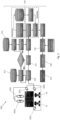
Fig. 1 shows an example of a pilot state monitoring system. -
Fig. 2 shows an example of a pilot posture recognition system. -
Fig. 3 shows an example of a pilot fall and object interaction detection system. -
Figure 1 generally shows an example of a pilotstate monitoring system 100. The a pilotstate monitoring system 100 is configured to monitor the activity of one or more pilots (e.g. P1 and P2) during flight. The pilotstate monitoring system 100 comprises one or more imaging devices including, for example, avisible light camera 101 and an infrared emitter/receiver 102 which acts as a time of flight detector. Optionally, the pilotstate monitoring system 100 may include one or more audio collectors 103 (e.g. a microphone). The infrared/depth camera 102 may assist in extracting and reconstructing a three-dimensional scene of the cockpit where the one or more pilots P1/P2 are situated. - As shown in
Figure 1 , data from at least one of theimage collector 101, the infrared/depth device 102 and theaudio collector 103 may be forwarded to be processed through adata buffer 110 to temporarily store data before it is processed. Thedata buffer 110 can buffer the data from at least one of theimage collector 101, the infrared emitter/receiver 102, and theaudio collector 103. The data may then be extrapolated from thedata buffer 110 in order to determine thepilot state 130. For example, data may be passed to one of the following subsystems: a) audio-visual pilotactivity recognition subsystem 112a, b) pilotdrowsiness recognition subsystem 112b, c) pilotposture recognition subsystem 112c, d) pilotpain recognition subsystem 112d, and e) pilotemotion recognition subsystem 112e. After one or more of thesesubsystems 112a-112e have processed the received data, the processed data is sent through to adecision module 120 where the processed data is analysed to determine apilot state 130. -
Figure 2 shows further detail of a pilotposture recognition subsystem 200. As shown inFigure 2 , a cockpit area may include one or more pilots (e.g. P1 and P2). As shown inFigure 2 , the cockpit area includes one or more imaging devices 202 including three RGB cameras (e.g. 202a, 202b, 202c) and two IR/depth sensors (e.g. 202d and 202e). In this example, the one or more imaging devices 202 are located to face the front side of the one or more pilots P1 and/or P2. The one or more imaging devices collect image data from the cockpit area, e.g. of the one or more pilots P1, P2. The image data may be taken during flight. - The modules and models of the
systems system - As can be seen in
Figure 2 , the image data is provided to aframe buffer 210 where the image data is temporarily stored for processing. The image data provided to theframe buffer 210 is transposed to two different branches. In the first branch, the image data is provided from theframe buffer 210 to adepth information module 211 that is configured to extract depth information from the image data. In the second branch, the image data is provided to apilot detection module 212 to determine a presence of one or more of the pilots P1, P2. If the presence of one or more of the pilots P1, P2 is detected, the image data is passed to apilot pose module 213 to estimate a pose of the one or more pilots P1, P2. The poses are detected by identifying, using a (pre-trained) human pose estimation model, a plurality two-dimensional keypoints corresponding to features of the one or more pilots P1, P2. The keypoint features include the pilot's eyes, nose, ears, shoulders, elbows, wrists, and hips. - The processed image data from the
depth information module 211 and the processed image data from the pilot posemodule 213 are then combined by theposture position module 214 to create a three-dimensional reconstruction of the pilot's pose (e.g. to determine three-dimensional positions of the keypoints of the one or more pilots in the cockpit). The three-dimensional keypoints of the one or more pilots in the cockpit are then fed into a LSTM network model of theposture position module 214. The LSTM network model is configured, e.g. (pre-trained), to determine feature relationships between the key points (i.e. the three-dimensional distance and angles between each key point) and to utilise the determined feature relationships to identify a three-dimensional posture. During training, the LSTM network model will learn to recognize or classify different postures based on characteristic/distinctive feature relationships. Accordingly, the LSTM network model is configured, e.g. trained, to recognise/infer postures (e.g. postures including at least head/neck leaning forward, backward, to right, or to left, body leaning to right or to left, normal upright, slouching, sliding down seat, falling off seat, etc.) of the one or more pilots from the three-dimensional keypoints. - Once the pilot posture(s) have been determined by the LSTM network of the pilot
posture position module 214, the information is sent to thedecision module 120 and/or an alert system/module 215 which may be additionally provided with information from other sensors and subsystems in the system (e.g. fromsubsystems 112a-e). Thedecision module 120 and/or alert system/module 215 can then determine afinal pilot state 130 and decide if an alert needs to be raised. - Another exemplary usage of the system is shown in
Figure 3 . In this example, as before, the image data provided to theframe buffer 210 is transposed to two different branches. However, in this case, in the second branch thepilot detection module 212 further comprises anobject detection module 220 configured to determine a presence of one or more objects in the cockpit (e.g. control levers, control panels including buttons and switches, sidesticks/joysticks, control pedals, and control wheels/yokes/tillers). If the presence of one or more objects are detected, theobject detection module 220 utilises the processed image data from thedepth information module 211 to create a three-dimensional reconstruction of the scene (e.g. to determine three-dimensional positions of the objects in the cockpit). - In the event that the system determines that one or more pilots have fallen (e.g. the posture position indicates that a pilot is falling/has fallen), the processed image data from the object detection module 220 (e.g. the three-dimensional object positions) and the processed image data from the posture position module 214 (e.g. the three-dimensional postures of the one or more pilots P1, P2) are passed to the pilot-
object module 222. The pilot-object interaction module 222, as shown inFigure 3 , comprises an LSTM network configured, e.g. trained, to recognise when a pilot-object interaction has occurred based on the three-dimensional relative positions of the pilot(s) P1, P2 and the objects. Therefore, for example, the pilot-object module 222 is able to determine if a pilot who has fallen (for any reason) has fallen onto or knocked the flight controls. - If the system determines that a pilot-object interaction has occurred after a fall, then this information is passed to the
decision module 120 and/or alert system/module 215. Thedecision module 120 and/oralert system 215 is configured to check the time at which the determined pilot-object interaction event occurred and identify if an action was input to a flight system log at the time of the determined pilot-object interaction event. If an action was input to the flight system log at the same time as a determined pilot-object interaction event, then thealert system 215 is configured to alert an aircraft management system/control system that the action input was a result of the determined pilot-object interaction. Accordingly, the aircraft management system/control system may be instructed to automatically address the action input (e.g. to rectify or undo the action performed by the inadvertent interaction with the flight controls), or notify aircraft crew (e.g. the remaining one or more pilots) and/or ground control and/or Air Traffic Control. Similarly, thealert system 215 may alert aircraft crew and/or ground control and/or Air Traffic Control that one or more pilots have fallen (e.g. even if a pilot-object interaction has not occurred). - In other words, the
system 200 is capable of recognising a first anomalous event (a pilot fall) and instructing the alert system/module 215 to raise a corresponding alert (e.g. to notify at least one of the aircraft management system, aircraft crew, ground control, and Air Traffic Control), and capable of recognising a second anomalous event (a pilot-object interaction after a pilot fall) and instructing the alert system/module 215 to check if a flight action input was a result of the determined pilot-object interaction and, if so, to raise a corresponding alert (e.g. to notify at least one of the aircraft management system, aircraft crew, ground control, and Air Traffic Control). - Although this disclosure has been described in terms of preferred examples, it should be understood that these examples are illustrative only and that the claims are not limited to those examples. Those skilled in the art will be able to make modifications and alternatives in view of the disclosure which are contemplated as falling within the scope of the appended claims.
Claims (15)
- A system (200), comprising:one or more imaging devices (202) configured to collect image data of a cockpit area of an aircraft;a pilot detection module (212) configured to determine a presence of one or more pilots (P1, P2) in the cockpit area based on the image data; anda pilot posture module (214) configured to determine three-dimensional posture of the one or more pilots based on the image data.
- The system of claim 1, wherein the pilot posture module (214) is capable of determining that a pilot is falling or has fallen.
- The system of claim 1 or claim 2, comprising an object detection module (220) configured to determine a presence and three-dimensional position of one or more objects in the cockpit area based on the image data.
- The system of claim 3 when dependent on claim 2, comprising a pilot-object module (222) configured to, if the pilot posture module (214) detects that one or more pilots has fallen, determine that a pilot-object interaction event has occurred based on the three-dimensional posture of the one or more pilots (P1, P2) and the three-dimensional positions of the one or more objects.
- The system of any preceding claim, wherein the system (200) is configured to pass the determined three-dimensional posture and/or the determined pilot-object interaction event to an alert system (120, 215).
- The system of claim 5, wherein the alert system (120, 215) is configured to:verify that an action has been input into a flight system log of the aircraft as a result of the determined pilot-object interaction event; andalert a control system of the aircraft that the action input was a result of the determined pilot-object interaction event.
- The system of claim 5 or 6, wherein the alert system (120, 215) is configured to:verify from the determined pilot activity that one or more pilots (P1, P2) have fallen; andalert aircraft crew and/or ground control and/or Air Traffic Control that one or more pilots have fallen.
- The system of any preceding claim, wherein the pilot posture module (214) comprises:a depth information module (211) configured to extract depth information from the image data; anda pilot pose module (213) configured to identify a plurality of two-dimensional keypoints corresponding to features of the one or more pilots (P1, P2) in the image data,wherein the pilot posture module (214) is configured to combine the depth information and the two-dimensional keypoints to determine three-dimensional posture of the one or more pilots in the cockpit.
- A method, comprising:collecting, using one or more imaging devices (202), image data of a cockpit area of an aircraft;determining, using a pilot detection module (212), a presence of one or more pilots in the cockpit area based on the image data; anddetermining, using a pilot posture module (214), three-dimensional posture of the one or more pilots (P1, P2) based on the image data.
- The method of claim 9, comprising:
determining, using the pilot posture module (214), that a pilot is falling or has fallen. - The method of claim 9 or claim 10, comprising:
determining, using an object detection image module (220), a presence and three-dimensional position of one or more objects in the cockpit area based on the image data. - The method of claim 11 when dependent on claim 10, comprising:
determining, using a pilot-object module (222), that a pilot-object interaction event has occurred based on the three-dimensional posture of the one or more pilots and the three-dimensional positions of the one or more objects. - The method of claim 12, comprising:verifying, using an alert system (120, 215), that an action has been input into a flight system log of the aircraft as a result of the determined pilot-object interaction event; andalerting, using the alert system (120, 215), a control system of the aircraft that the action input was a result of the determined pilot-object interaction event.
- The method of any of claims 10 to 13, comprising:
alerting, using an alert system (120, 215), aircraft crew and/or ground control and/or Air Traffic Control that one or more pilots have fallen. - The method of any of claims 9 to 14, comprising:extracting, using a depth information module (211) of the pilot posture module (214), depth information from the image data;identifying, using a pilot pose module (213) of the pilot posture module (214), a plurality of two-dimensional keypoints corresponding to features of the one or more pilots (P1, P2) in the image data; andcombining, using the pilot posture module (214), the depth information and the two-dimensional keypoints to determine three-dimensional posture of the one or more pilots in the cockpit.
Priority Applications (2)
| Application Number | Priority Date | Filing Date | Title |
|---|---|---|---|
| EP23164433.7A EP4439477B1 (en) | 2023-03-27 | 2023-03-27 | Pilot posture recognition system and method |
| US18/593,332 US20240331387A1 (en) | 2023-03-27 | 2024-03-01 | Pilot posture recognition system and method |
Applications Claiming Priority (1)
| Application Number | Priority Date | Filing Date | Title |
|---|---|---|---|
| EP23164433.7A EP4439477B1 (en) | 2023-03-27 | 2023-03-27 | Pilot posture recognition system and method |
Publications (2)
| Publication Number | Publication Date |
|---|---|
| EP4439477A1 true EP4439477A1 (en) | 2024-10-02 |
| EP4439477B1 EP4439477B1 (en) | 2026-04-29 |
Family
ID=85776157
Family Applications (1)
| Application Number | Title | Priority Date | Filing Date |
|---|---|---|---|
| EP23164433.7A Active EP4439477B1 (en) | 2023-03-27 | 2023-03-27 | Pilot posture recognition system and method |
Country Status (2)
| Country | Link |
|---|---|
| US (1) | US20240331387A1 (en) |
| EP (1) | EP4439477B1 (en) |
Citations (3)
| Publication number | Priority date | Publication date | Assignee | Title |
|---|---|---|---|---|
| US20190090800A1 (en) * | 2017-09-22 | 2019-03-28 | Aurora Flight Sciences Corporation | Systems and Methods for Monitoring Pilot Health |
| US20220230522A1 (en) * | 2021-01-18 | 2022-07-21 | Seeing Machines Limited | Flight Crew Fatigue And Controlled Rest Management System |
| US20220265187A1 (en) * | 2021-02-22 | 2022-08-25 | Dassault Aviation | System for monitoring the operational status of an aircraft crew, and associated method |
Family Cites Families (7)
| Publication number | Priority date | Publication date | Assignee | Title |
|---|---|---|---|---|
| US10552675B2 (en) * | 2014-03-12 | 2020-02-04 | Seeing Machines Limited | Method and apparatus for eye detection from glints |
| EP3259734B1 (en) * | 2015-02-20 | 2024-07-24 | Seeing Machines Limited | Glare reduction |
| US10271042B2 (en) * | 2015-05-29 | 2019-04-23 | Seeing Machines Limited | Calibration of a head mounted eye tracking system |
| US11941894B2 (en) * | 2018-04-19 | 2024-03-26 | Seeing Machines Limited | Infrared light source protective system |
| US12198312B2 (en) * | 2018-06-18 | 2025-01-14 | Seeing Machines Limited | High frame rate image pre-processing system and method |
| US12371184B2 (en) * | 2022-01-03 | 2025-07-29 | Honeywell International Inc. | Systems and methods for presenting a qualitative risk assessment for an aircraft to perform a flight procedure |
| JP2024029755A (en) * | 2022-08-22 | 2024-03-06 | シーイング マシーンズ リミテッド | Automatic antiglare mirror |
-
2023
- 2023-03-27 EP EP23164433.7A patent/EP4439477B1/en active Active
-
2024
- 2024-03-01 US US18/593,332 patent/US20240331387A1/en active Pending
Patent Citations (3)
| Publication number | Priority date | Publication date | Assignee | Title |
|---|---|---|---|---|
| US20190090800A1 (en) * | 2017-09-22 | 2019-03-28 | Aurora Flight Sciences Corporation | Systems and Methods for Monitoring Pilot Health |
| US20220230522A1 (en) * | 2021-01-18 | 2022-07-21 | Seeing Machines Limited | Flight Crew Fatigue And Controlled Rest Management System |
| US20220265187A1 (en) * | 2021-02-22 | 2022-08-25 | Dassault Aviation | System for monitoring the operational status of an aircraft crew, and associated method |
Also Published As
| Publication number | Publication date |
|---|---|
| EP4439477B1 (en) | 2026-04-29 |
| US20240331387A1 (en) | 2024-10-03 |
Similar Documents
| Publication | Publication Date | Title |
|---|---|---|
| US12424015B2 (en) | Image processing apparatus and method for recognizing state of subject | |
| EP4214688B1 (en) | Vehicle occupant monitoring system and method | |
| JP7692942B2 (en) | Spoofing prevention system | |
| JP6166297B2 (en) | Posture estimation device | |
| JP2020135551A (en) | Object recognition device, object recognition method, and object recognition program | |
| KR20200113743A (en) | Method and apparatus for estimating and compensating human's pose | |
| JP2019159518A (en) | Visual state detection apparatus, visual state detection method, and visual state detection program | |
| CN113615166A (en) | Accident detection device and accident detection method | |
| CN110321820A (en) | A kind of sight drop point detection method based on contactless device | |
| CN106529500A (en) | Information processing method and system | |
| JP6773825B2 (en) | Learning device, learning method, learning program, and object recognition device | |
| US20250001960A1 (en) | Passenger monitoring apparatus, passenger monitoring method, and non-transitory computer-readable medium | |
| WO2021046172A1 (en) | Biometric data capturing and analysis using a hybrid sensing system | |
| EP4439477B1 (en) | Pilot posture recognition system and method | |
| CN120986420B (en) | Driver on-duty state early warning system based on deep learning | |
| JP7718854B2 (en) | Object recognition system and object recognition method | |
| JP2021022953A (en) | Information processing device, information processing method, and program | |
| Ahmed et al. | Fall Detection from Indoor Videos using MediaPipe and Handcrafted Feature | |
| US10755540B1 (en) | Video alert and secondary verification system and method | |
| AU2021418124B2 (en) | Disorderly biometric boarding | |
| CN111358445A (en) | Morning check machine | |
| US20250069402A1 (en) | Information processing apparatus, information processing method, and non-transitory storage medium | |
| EP4421757A1 (en) | Audio-visual pilot activity recognition system and method | |
| TW201205449A (en) | Video camera and a controlling method thereof | |
| KR101607569B1 (en) | Apparatus for detecting person and method thereof |
Legal Events
| Date | Code | Title | Description |
|---|---|---|---|
| PUAI | Public reference made under article 153(3) epc to a published international application that has entered the european phase |
Free format text: ORIGINAL CODE: 0009012 |
|
| STAA | Information on the status of an ep patent application or granted ep patent |
Free format text: STATUS: THE APPLICATION HAS BEEN PUBLISHED |
|
| AK | Designated contracting states |
Kind code of ref document: A1 Designated state(s): AL AT BE BG CH CY CZ DE DK EE ES FI FR GB GR HR HU IE IS IT LI LT LU LV MC ME MK MT NL NO PL PT RO RS SE SI SK SM TR |
|
| STAA | Information on the status of an ep patent application or granted ep patent |
Free format text: STATUS: REQUEST FOR EXAMINATION WAS MADE |
|
| 17P | Request for examination filed |
Effective date: 20250402 |
|
| GRAP | Despatch of communication of intention to grant a patent |
Free format text: ORIGINAL CODE: EPIDOSNIGR1 |
|
| STAA | Information on the status of an ep patent application or granted ep patent |
Free format text: STATUS: GRANT OF PATENT IS INTENDED |
|
| RIC1 | Information provided on ipc code assigned before grant |
Ipc: G06V 10/143 20220101AFI20251014BHEP Ipc: G06V 10/46 20220101ALI20251014BHEP Ipc: G06V 10/75 20220101ALI20251014BHEP Ipc: G06V 10/80 20220101ALI20251014BHEP Ipc: G06V 20/52 20220101ALI20251014BHEP Ipc: G06V 20/59 20220101ALI20251014BHEP Ipc: G06V 40/10 20220101ALI20251014BHEP Ipc: G06V 40/20 20220101ALI20251014BHEP Ipc: G06T 7/73 20170101ALI20251014BHEP Ipc: G05D 1/00 20240101ALI20251014BHEP Ipc: A61B 5/18 20060101ALI20251014BHEP Ipc: B64D 45/00 20060101ALI20251014BHEP |
|
| INTG | Intention to grant announced |
Effective date: 20251024 |
|
| GRAS | Grant fee paid |
Free format text: ORIGINAL CODE: EPIDOSNIGR3 |
|
| GRAA | (expected) grant |
Free format text: ORIGINAL CODE: 0009210 |
|
| STAA | Information on the status of an ep patent application or granted ep patent |
Free format text: STATUS: THE PATENT HAS BEEN GRANTED |
|
| AK | Designated contracting states |
Kind code of ref document: B1 Designated state(s): AL AT BE BG CH CY CZ DE DK EE ES FI FR GB GR HR HU IE IS IT LI LT LU LV MC ME MK MT NL NO PL PT RO RS SE SI SK SM TR |
|
| REG | Reference to a national code |
Ref country code: CH Ref legal event code: F10 Free format text: ST27 STATUS EVENT CODE: U-0-0-F10-F00 (AS PROVIDED BY THE NATIONAL OFFICE) Effective date: 20260429 Ref country code: GB Ref legal event code: FG4D |