EP4439473A1 - Technique for rendering hidden structures with clip planes - Google Patents
Technique for rendering hidden structures with clip planes Download PDFInfo
- Publication number
- EP4439473A1 EP4439473A1 EP23164672.0A EP23164672A EP4439473A1 EP 4439473 A1 EP4439473 A1 EP 4439473A1 EP 23164672 A EP23164672 A EP 23164672A EP 4439473 A1 EP4439473 A1 EP 4439473A1
- Authority
- EP
- European Patent Office
- Prior art keywords
- data set
- rendering
- volumetric data
- medical
- medical image
- Prior art date
- Legal status (The legal status is an assumption and is not a legal conclusion. Google has not performed a legal analysis and makes no representation as to the accuracy of the status listed.)
- Pending
Links
Images




Classifications
-
- G—PHYSICS
- G06—COMPUTING OR CALCULATING; COUNTING
- G06T—IMAGE DATA PROCESSING OR GENERATION, IN GENERAL
- G06T15/00—Three-dimensional [3D] image rendering
- G06T15/08—Volume rendering
-
- G—PHYSICS
- G06—COMPUTING OR CALCULATING; COUNTING
- G06T—IMAGE DATA PROCESSING OR GENERATION, IN GENERAL
- G06T7/00—Image analysis
- G06T7/10—Segmentation; Edge detection
-
- G—PHYSICS
- G06—COMPUTING OR CALCULATING; COUNTING
- G06T—IMAGE DATA PROCESSING OR GENERATION, IN GENERAL
- G06T15/00—Three-dimensional [3D] image rendering
- G06T15/10—Geometric effects
- G06T15/30—Clipping
-
- G—PHYSICS
- G06—COMPUTING OR CALCULATING; COUNTING
- G06T—IMAGE DATA PROCESSING OR GENERATION, IN GENERAL
- G06T15/00—Three-dimensional [3D] image rendering
- G06T15/50—Lighting effects
-
- G—PHYSICS
- G06—COMPUTING OR CALCULATING; COUNTING
- G06T—IMAGE DATA PROCESSING OR GENERATION, IN GENERAL
- G06T19/00—Manipulating three-dimensional [3D] models or images for computer graphics
-
- G—PHYSICS
- G06—COMPUTING OR CALCULATING; COUNTING
- G06T—IMAGE DATA PROCESSING OR GENERATION, IN GENERAL
- G06T2207/00—Indexing scheme for image analysis or image enhancement
- G06T2207/10—Image acquisition modality
- G06T2207/10072—Tomographic images
- G06T2207/10081—Computed x-ray tomography [CT]
-
- G—PHYSICS
- G06—COMPUTING OR CALCULATING; COUNTING
- G06T—IMAGE DATA PROCESSING OR GENERATION, IN GENERAL
- G06T2207/00—Indexing scheme for image analysis or image enhancement
- G06T2207/10—Image acquisition modality
- G06T2207/10072—Tomographic images
- G06T2207/10104—Positron emission tomography [PET]
-
- G—PHYSICS
- G06—COMPUTING OR CALCULATING; COUNTING
- G06T—IMAGE DATA PROCESSING OR GENERATION, IN GENERAL
- G06T2207/00—Indexing scheme for image analysis or image enhancement
- G06T2207/10—Image acquisition modality
- G06T2207/10132—Ultrasound image
-
- G—PHYSICS
- G06—COMPUTING OR CALCULATING; COUNTING
- G06T—IMAGE DATA PROCESSING OR GENERATION, IN GENERAL
- G06T2207/00—Indexing scheme for image analysis or image enhancement
- G06T2207/20—Special algorithmic details
- G06T2207/20112—Image segmentation details
- G06T2207/20132—Image cropping
-
- G—PHYSICS
- G06—COMPUTING OR CALCULATING; COUNTING
- G06T—IMAGE DATA PROCESSING OR GENERATION, IN GENERAL
- G06T2210/00—Indexing scheme for image generation or computer graphics
- G06T2210/41—Medical
-
- G—PHYSICS
- G06—COMPUTING OR CALCULATING; COUNTING
- G06T—IMAGE DATA PROCESSING OR GENERATION, IN GENERAL
- G06T2219/00—Indexing scheme for manipulating 3D models or images for computer graphics
- G06T2219/008—Cut plane or projection plane definition
Definitions
- Clipping in the context of volume rendering is a method of specifying which regions of the volume should be rendered.
- clipping techniques are essential due to the complexity of the human anatomy. Clipping is used for exploring the inner structures of the data that would otherwise be obstructed for the viewer.
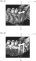
- FIGs. 3A and 3B show a rendered image of a CT study (also denoted as CT scan) of a patient's spine 304 after surgery without and with a clip plane, respectively.
- the screws 302; 302' are (at least partially) hidden for the camera by the bone structures 304 as depicted in the image 300 in Fig. 3A , and they become visible only once a clip plane is added, and/or activated, at the right location with the precise orientation, as exemplified by the image 301 in Fig. 3B .
- Differentiable renderers have been used in the past to tackle problems without introducing discontinuities, such as estimating optimal camera viewpoints or transfer functions to approximate a reference image.
- discontinuities such as estimating optimal camera viewpoints or transfer functions to approximate a reference image.
- no use of differentiable renderers to estimate the position and orientation of clip planes has been described, as the presence of clip planes introduces discontinuities, making the rendering problem non differentiable.
- Differentiable volume rendering algorithms have gained a lot of attention in recent years due to their ability to learn input parameters to render a scene that can optimize an objective function. These algorithms can be designed, for example, to create a rendering that closely matches a reference image, or to find the camera parameters that provide the best view for a particular scene.
- Li et al. [Li18] present a differentiable renderer for triangular meshes overcoming the problem of geometric discontinuities and occlusions using an edge sampling approach. At the edges of objects, both sides, the background and the foreground of the edge, are sampled, and contributions for both sides are used.
- the authors proposed an approximate algorithm for triangle meshes that avoids edge sampling through reparameterization converting boundary integrals to area integrals.
- the approach based on meshes cannot be directly applied to the case of volume rendering.
- Weiss et al. present a differentiable volume renderer. They optimize the continuous parameters of the rendering process and describe some practical applications. In particular, Weiss et al. use the differentiable renderer to find optimal camera parameters to maximize image entropy or to determine the transfer function that best match a reference image.
- Optimizing locations / positions, and/or orientations of clip planes, clip surfaces and crop boxes is therefore conventionally performed manually and in a highly time-consuming manner, preventing any use in real-time applications, e.g., for surgical guidance, validation (also denoted as verification, checkup, and/or examining) of a performed surgical procedure, and/or diagnostic purposes.
- efficiently optimizing locations / positions, and/or orientations of clip planes, clip surfaces and crop boxes conventionally requires extensive training and experience by the user (e.g., a medical practitioner).
- an object of the present invention is to provide an efficient (e.g., in terms of time and/or computing resources) solution for incorporating the differentiable rendering of hidden structures within medical images.
- an object of the present invention is to provide a technique for incorporating clip planes, clip surfaces, and/or crop boxes in differentiable (e.g., volume) rendering of medical data sets, in particular while preserving all the advantages of differentiable rendering in relation to continuous rendering parameters such as camera, transfer function, lighting, opacity and/or color.
- This object is solved by a method for rendering a hidden structure of a volumetric data set when rendering a medical image based on the volumetric data set, by a computing device, by a system comprising the computing device, by a computer program (also denoted as computer program product), and by a computer-readable medium according to the appended independent claims.
- a method for rendering a hidden structure of a volumetric data set when rendering a medical image based on the volumetric data set by a computing device, by a system comprising the computing device, by a computer program (also denoted as computer program product), and by a computer-readable medium according to the appended independent claims.
- a (in particular computer-implemented) method for rendering a hidden structure of a volumetric data set when rendering a medical image based on the volumetric data set is provided.
- the volumetric data set is received from a medical scanner.
- the method comprising a step of receiving the volumetric data set from the medical scanner.
- the method further comprises a step of receiving a reference information indicative of (e.g., an initial value of) at least one parameter for a clip plane within a medical image for rendering the hidden structure comprised in the received volumetric data set.
- the method further comprises a step of applying a differentiable rendering (DR) algorithm on the received volumetric data set for rendering the medical image with the hidden structure. Applying the DR algorithm comprises determining a light accumulation along a viewing ray.
- DR differentiable rendering
- the clip plane is approximated by including a smooth approximation to a Dirac delta distribution in the determining of the light accumulation along the viewing ray.
- the smooth approximation to the Dirac delta distribution depends on the (e.g., initial value of the) at least one parameter comprised in the received reference information.
- Applying the DR algorithm further comprises optimizing the at least one parameter for the clip plane by optimizing an objective function.
- the method still further comprises a step of outputting, based on the applied DR algorithm, the medical image with the hidden structure. The hidden structure is visible in the medical image output for final rendering, and/or for display.
- an optimal position of a clip plane for medical purposes can be automatically determined, leading to time saving from receiving the volumetric data set from the medical scanner to performing the final rendering (also denoted as output for display, or displaying).
- a positioning of one or more implants, in particular after a surgical procedure in which the implants were placed, can be controlled by the inventive technique in a timely manner.
- a diagnosis of a lesion e.g., a tumor and/or a torn ligament
- an organ and/or anatomical structure e.g., within the liver, a kidney, a joint and/or a ligament
- the medical image with optimized clip plane as well as optimized further (in particular continuous) rendering parameters can be made available such that a separate appointment date (e.g., on a different day) for a patient for reviewing a diagnostic result (and/or medical analysis) of the acquisition of the volumetric data set by means of the medical scanner can be avoided.
- the volumetric data set may also be denoted as three-dimensional data set.
- the volumetric data set may be received from a medical scanner comprising a (e.g., predetermined) imaging modality.
- the imaging modality may comprise computed tomography (CT), magnetic resonance imaging (MRI), ultrasound (US), positron emission tomography (PET), and/or single-photon emission computed tomography (SPECT).
- the volumetric data set may comprise a (e.g., cine) series of three-dimensional data sets over a time interval. Further alternatively or in addition, the volumetric data set may vary over time (e.g., over a time period of acquisition from the medical scanner).
- the structure(s) of interest may be occluded (also: concealed, obscured, and/or hidden) behind an anatomical structure, an organ's surface and/or behind a further structure, in particular comprising an implant or other synthetical structures, in the volumetric data set, when rendered without applying any clip plane.
- the clip plane also: clipping plane
- the occluding structure may be removed from the rendered medical image.
- the hidden structure may be made fully, or at least partially, visible (also: visualized, and/or shown) on the (e.g., finally rendered and/or displayed) medical image.
- the clip plane may also be denoted as clip surface, and/or clipping plane.
- the clip plane may comprise two or more components, and/or clip planes, in particular at relative non-vanishing angles.
- a crop box may be based, and/or may comprise, a plurality of clip planes.
- a crop box may be based, and/or may comprise one or more spatially limited (and/or finitely extended) clip planes.
- a clip plane may be used to make everything in front of it transparent. Further alternatively or in addition, by the change of transparency in front of the clip plane, usually a viewing ray traversal does not need to stop at the clip plane.
- the hidden structure may comprise an implant, a synthetical structure and/or an anatomical structure.
- the implant may comprise a stent, a screw, and/or an artificial joint, e.g., an artificial hip.
- the implant may comprise a sensory implant, a neurological implant, and/or a cardiovascular medical device (e.g., a cardiac stimulator, and/or pacemaker).
- the anatomical structure may comprise an abnormality (also denoted as pathology), a lesion, a tumor, and/or a (e.g., at least partially torn) ligament.
- the at least one parameter for the clip plane may comprise a position, and/or an orientation, of the clip plane.
- the reference information may comprise a reference image, e.g., from a database for a predetermined type of (in particular anatomical) structures, and/or organs, comprised in the volumetric data set.
- the reference information may comprise a position information for the clip plane, e.g., based on a segmentation of (in particular anatomical) structures, and/or organs, comprised in the volumetric data set.
- the at least one parameter may be indicative of applying the clip plane approximately centrally within an organ.
- the DR may also be denoted as differentiable volume rendering (DVR).
- DVR differentiable volume rendering
- inventive DR algorithm may extend the functionalities, and/or workings, of the DVRs of [Weiss22].
- Applying the DR may comprise applying a rendering algorithm.
- the rendering algorithm may comprise raycasting, and/or (e.g., Monte Carlo) path tracing.
- a (e.g., sharp) clip plane may have a vanishing thickness, and/or may lead to a discontinuity in the volumetric data, and/or may preclude (and/or make impossible) the use of the DR algorithm.
- a clip plane may be represented by the Dirac delta distribution (also denoted as ⁇ -distribution, Dirac delta function, and/or ⁇ -function).
- the Dirac delta distribution may be non-vanishing, and/or at any location (e.g., position, and/or orientation) outside the clip plane, the Dirac delta distribution may be vanishing.
- the (e.g., sharp) clip plane may be approximated by a smoothed clip plane (which may also be denoted as soft clip plane).
- the smoothed clip plane may be represented by a smooth function (e.g., a Gaussian function) approximating the Dirac delta distribution with non-vanishing values within a non-vanishing thickness of the (e.g., smoothed) clip plane.
- the smooth function e.g., the Gaussian function
- the smooth function may rapidly approximate a vanishing value outside the thickness of the (e.g., smoothed) clip plane.
- the volumetric data may remain continuous, and/or the DR algorithm may remain applicable.
- further (e.g., continuous) rendering parameters may still be optimized by means of the DR algorithm.
- applying the DR algorithm may comprise optimizing the at least one parameter for the clip plane (briefly also denoted as clip plane parameter), in particular the position and/or orientation of the clip plane, by optimizing an objective function.
- the objective function may comprise a loss function, in particular for a reference image as the reference information.
- the loss function may be optimized by minimizing the difference between (briefly also denoted as: matching) the reference image and the medical image with the visibly rendered hidden structure, or at least parts thereof.
- optimizing the loss function may comprise minimizing a mean square difference (also denoted as mean square error, MSE) between pixel values, maximizing structural similarities (also denoted as structural similarity index measure, SSIM), and/or alignment of feature extraction.
- Image registration may be used, e.g., to match the medical image to a previous scan. Alternatively or in addition, image registration is not necessarily used for the image comparison. Further alternatively or in addition, image registration may, e.g., be used to map the target image (and/or reference image) into the rendered image before the loss function is computed, and/or before a value of the loss function is determined.
- the objective function may comprise (e.g., maximizing) an image entropy, in particular for the reference information comprising a position information relative to an (e.g., anatomical) structure, and/or organ, comprised in the volumetric data set.
- the at least one parameter may specify to initially set the clip plane centrally, e.g., based on a segmentation and/or classification, within an organ.
- the optimizing of the objective function may comprise a combination of (e.g., minimizing) one or more loss functions, and/or (e.g., maximizing) image entropy.
- the applying of the DR algorithm may be iterative.
- the received at least one parameter may comprise, and/or may determine, an initial value of the one or more clip plane parameters.
- the optimizing of the objective function may comprise varying the one or more clip plane parameters.
- the optimization of the objective function, and/or of the at least one parameter for the clip plane may be gradient-based.
- the inventive technique may be applied to more than one clip plane within a volumetric data set.
- more than one clip plane for the rendering of the medical image more than one hidden structure (e.g., several implants) may be rendered visible.
- the more than one clip plane may be applied at relative non-vanishing angles.
- a pie-slice-shaped section (and/or wedge) of a human skull may be cut out of the medical image in order to provide a view on the brain.
- input parameters to the DR algorithm may comprise a camera parameter (also denoted as view parameter), and/or a transfer function (TF).
- TF transfer function
- voxel values may be assigned to color, and/or opacity, of a pixel of the medical image.
- the hidden structure may comprise an implant, in particular a stent, a screw, and/or an artificial joint, in particular an artificial hip.
- the hidden structure may comprise an anatomical structure, in particular a lesion, a tumor, and/or a ligament.
- the received reference information may comprise a medical reference image.
- the medical reference image may comprise a, e.g., previously stored medical image, in particular comprising a manually set clip plane.
- the medical reference image may comprise a synthetic image, and/or a painted (also: sketched, and/or drawn) image.
- medical images may be retrieved from a medical journal and/or a book, from a medical image database and/or a medical image library, e.g., provided by an medical expert.
- the objective function may comprise a loss function depending on the medical reference image. Optimizing the loss function may comprise minimizing, and/or maximizing, the loss function.
- the loss function may comprise the difference between the reference image and the medical image with the visibly rendered hidden structure.
- the loss function may comprise a mean square difference (and/or MSE) between pixel values.
- the loss function may be based on structural similarities (and/or a SSIM), and/or on feature extraction.
- the received reference information may comprise a (e.g., initial value of a) position relative to an anatomical structure, and/or relative to an organ.
- the (in particular initial value of the) position relative to the anatomical structure, and/or relative to the organ may be obtained by performing a segmentation, and/or a classification of the anatomical structure, and/or the organ, captured in the volumetric data set.
- the (in particular initial value of the) position may, e.g., comprise a central location (e.g., position, and/or orientation) within the segmented, and/or classified, anatomical structure, and/or organ.
- the objective function may comprise an image entropy.
- Optimizing the objective function may comprise maximizing the image entropy.
- structures, in particular lesions, within the volumetric data set may be rendered visible (also: visualized, and/or made visible).
- a lesion may correspond to, and/or may produce, an inhomogeneity in the medical image, which can be rendered visible by using the image entropy, e.g., as a measure for the (in particular image) inhomogeneity.
- Maximizing the image entropy may be combinable with providing the initial value of the at least one parameter for the clip plane (also: clip plane parameter) by means of a reference image.
- the objective function used for optimizing the at least one parameter may be determined (and/or selected) based on the received reference information.
- a reference image if a reference image is provided, different image quality metrics may be used as loss functions. Further alternatively or in addition, if no reference image is provided, a non-reference loss function, and/or non-reference metric, needs to be used. Information entropy may be an example of a non-reference loss function.
- the at least one parameter of the clip plane may comprise a position, and/or an orientation, of the clip plane within the volumetric data set.
- the smooth approximation to the Dirac delta distribution may comprises a Gaussian function.
- the smooth approximation to the Dirac delta distribution may also be denoted as nascent delta function.
- the smooth approximation to Dirac's delta distribution may be discretized per voxel, and/or per pixel.
- the light accumulation may be determined by means of raycasting, (e.g., Monte Carlo) path tracing, half-angle slicing, and/or interactive volume lighting, IVL.
- raycasting e.g., Monte Carlo path tracing
- half-angle slicing e.g., half-angle slicing
- IVL interactive volume lighting
- the light accumulation may comprise local illumination effects (e.g., light attenuating from voxel to voxel due to the voxel's opacity, and/or from pixel to pixel due to the pixel's opacity), and/or global illumination effects (e.g., due to light scattering).
- local illumination effects e.g., light attenuating from voxel to voxel due to the voxel's opacity, and/or from pixel to pixel due to the pixel's opacity
- global illumination effects e.g., due to light scattering
- the at least one parameter of a clip plane may comprise two or more parameters, in particular of two or more clip planes.
- the two or more clip planes may be non-parallel, and/or at non-vanishing angles. Thereby, a slice (and/or wedge) may be cut out of a rendered (e.g., anatomical) structure.
- the medical scanner may be selected from the group of a CT scanner, an MRI scanner, a US scanner, a PET scanner, and/or a SPECT scanner.
- a computing device for rendering a hidden structure of a volumetric data set when rendering a medical image based on the volumetric data set.
- the volumetric data set is received from a medical scanner.
- the computing device comprises a volumetric data set receiving interface configured for receiving a volumetric data set from a medical scanner.
- the computing device further comprises a reference information receiving interface configured for receiving a reference information indicative of (e.g., an initial value of) at least one parameter for a clip plane within a medical image for rendering the hidden structure comprised in the received volumetric data set.
- the computing device further comprises a processing module (e.g., a CPU, and/or GPU) configured for applying a DR algorithm on the received volumetric data set for rendering the medical image with the hidden structure.
- a processing module e.g., a CPU, and/or GPU
- Applying the DR algorithm comprises determining a light accumulation along a viewing ray.
- the clip plane is approximated by including a smooth approximation to a Dirac delta distribution in the determining of the light accumulation along the viewing ray.
- the smooth approximation to the Dirac delta distribution depends on the (e.g., initial value of the) at least one parameter comprised in the received reference information.
- Applying the DR algorithm further comprises optimizing the at least one parameter for the clip plane by optimizing an objective function.
- the computing device still further comprises an outputting interface configured for outputting, based on the applied DR algorithm, the medical image with the hidden structure.
- the hidden structure is visible in the medical image output for final rendering, and/or for display.
- the computing device may be configured to perform the method according to the method aspect.
- the computing device may comprise any feature disclosed in the context of the method according to the method aspect.
- a system for rendering a hidden structure of a volumetric data set when rendering a medical image based on the volumetric data set is provided.
- the volumetric data set is received from a medical scanner.
- the system comprises one or more medical scanners configured for providing a volumetric data set.
- the system further comprises a computing device according to the device aspect.
- the volumetric data set receiving interface of the computing device is configured for receiving the volumetric data set from any one of the one or more medical scanners.
- the system still further comprises a display device (briefly also: display) configured for receiving a medical image with a hidden structure from the outputting interface of the computing device.
- the display device is further configured for displaying, and/or final rendering, the received medical image with the hidden structure.
- a computer program comprising program elements which induce a computing device to carry out the steps of the method, according to the method aspect, for rendering a hidden structure of a volumetric data set when rendering a medical image based on the volumetric data set is provided.
- the steps of the method are carried out when the program elements are loaded into a memory of the computing device.
- a computer-readable medium on which program elements are stored that can be read and executed by a computing device in order to perform steps of the method, according to the method aspect, for rendering a hidden structure of a volumetric data set when rendering a medical image based on the volumetric data set is provided.
- the steps of the method are performed when the program elements are executed by the computing device.
- Fig. 1 schematically illustrates an exemplary embodiment of a computer-implemented method for rendering a hidden structure of a volumetric data set when rendering a medical image based on the volumetric data set, which is received from a medical scanner.
- the method is generally referred to by the reference sign 100.
- the method 100 comprises a step S102 of receiving the volumetric data set from the medical scanner.
- the method 100 further comprises a step S104 of receiving a reference information indicative of at least one parameter for a clip plane within a medical image for rendering the hidden structure comprised in the received S102 volumetric data set.
- the method 100 further comprises a step S106 of applying a differentiable rendering (DR) algorithm on the received S102 volumetric data set for rendering the medical image with the hidden structure.
- Applying S106 the DR algorithm comprises determining a light accumulation along a viewing ray.
- the clip plane is approximated by including a smooth approximation to a Dirac delta distribution in the determining of the light accumulation along the viewing ray.
- the smooth approximation to the Dirac delta distribution depends on the at least one parameter comprised in the received S104 reference information.
- Applying S106 the DR algorithm further comprises optimizing the at least one parameter for the clip plane by optimizing an objective function.
- the method 100 still further comprises a step S108 of outputting, based on the applied S106 DR algorithm, the medical image with the hidden structure.
- the hidden structure is visible in the medical image outputted for final rendering, and/or for display.
- Fig. 2 schematically illustrates an exemplary embodiment of a computing device for rendering a hidden structure of a volumetric data set when rendering a medical image based on the volumetric data set, which is received from a medical scanner.
- the computing device is generally referred to by the reference sign 200.
- the computing device 200 comprises a volumetric data set receiving interface 202 configured for receiving a volumetric data set from a medical scanner.
- the computing device 200 further comprises a reference information receiving interface 204 configured for receiving a reference information indicative of at least one parameter for a clip plane within a medical image for rendering the hidden structure comprised in the received volumetric data set.
- the computing device 200 further comprises a processing module 206 configured for applying a DR algorithm on the received volumetric data set for rendering the medical image with the hidden structure.
- Applying the DR algorithm comprises determining a light accumulation along a viewing ray.
- the clip plane is approximated by including a smooth approximation to a Dirac delta distribution in the determining of the light accumulation along the viewing ray.
- the smooth approximation to the Dirac delta distribution depends on the at least one parameter comprised in the received reference information.
- Applying the DR algorithm further comprises optimizing the at least one parameter for the clip plane by optimizing an objective function.
- the computing device 200 still further comprises an outputting interface 208 configured for outputting, based on the applied DR algorithm, the medical image with the hidden structure.
- the hidden structure is visible in the medical image outputted for final rendering, and/or for display.
- the processing module 206 may be embodied by a processor and/or a central processing unit (CPU), and/or a graphics processing unit (GPU).
- CPU central processing unit
- GPU graphics processing unit
- the computing device 200 may comprise a memory 210.
- volumetric data set receiving interface 202 may be comprised in a common (e.g., input-output) interface 212.
- the computing device 200 may be configured for performing the method 100.
- a system for rendering a hidden structure of a volumetric data set when rendering a medical image based on the volumetric data set, which is received from a medical scanner may comprise one or more medical scanners for acquiring the volumetric data set, a computing device (e.g., the computing device 200) for performing the method 100, and a display device.
- the display device may comprise a monitor and/or screen, and/or an extended reality (XR) device, in particular an XR headset.
- XR may be an umbrella term for augmented reality (AR), and/or virtual reality (VR).
- the XR device may comprise a head-mounted display (HMD), and/or a head-up display (HUD).
- HMD head-mounted display
- HUD head-up display
- inventive technique e.g., comprising the method 100, the computing device 200, and/or the system
- technique for inverse volume rendering with clipping may alternatively be denoted as technique for inverse volume rendering with clipping.
- a differentiable renderer e.g., in performing the method step S106, and/or embodied by the processing module 206 is used to predict one or more optimal clip plane parameters to optimize an objective function.
- the clip can serve to describe the presence of lesions, and/or the viewpoint to best visualize stents, screws, artificial joints, and/or any further implant.
- the inventive technique can be used to match a reference image from a medical database or a medical illustration.
- Rendering a three-dimensional (3D) scene may comprise the process of generating a two-dimensional (2D) image I by simulating the interaction of the light with the objects in the scene (and/or comprised in the volumetric data set).
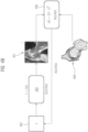
- differentiable renderers at reference sign 404 aim at solving the inverse problem, that is, predicting the scene parameters x at reference sign 402 from a particular medical image I, as exemplified at reference sign 401.
- DR algorithms work by propagating derivatives with respect to the input parameters x to maximize a loss function z(I), usually by some form of gradient-based optimization technique, as indicated at reference sign 406.
- Fig. 4A schematically illustrates a differentiable renderer 404 designed to learn input parameters x at reference sign 402 based on a general loss function z(I) at reference sign 406.
- the medical image I at reference sign 401 in Fig. 4A provides an example of a cross section of (e.g., patient's) left kidney rendered by using a (e.g., smoothed) clip plane.
- the clip plane for the rendered medical image I at reference sign 401 in Fig. 4A may, e.g., be obtained by providing a position (e.g., approximately centrally within the left kidney) as reference information for the clip plane parameter.
- the location (e.g., position, and/or orientation) of the clip plane in the medical image I at reference sign 401 of Fig. 4A may be determined based on maximizing image entropy (e.g., as the objective function z(I) at reference sign 406 in Fig.
- the hidden structure shown in the rendered medical image I at reference sign 401 in Fig. 4A comprises the internal structures (e.g., thickness of the renal cortex, renal medulla, renal papilla, renal pyramids, renal columns) of the left kidney.
- Fig. 4B schematically illustrates a differentiable renderer 404 with loss function z(I) at reference sign 406 designed to learn input parameters x at reference sign 402 to match a reference image R (also denoted as target image) as exemplified at reference signs 408 and 406.
- the medical image I at reference sign 401 of Fig. 4B provides an example of a cross section of a left hip joint using a (e.g., smoothed) clip plane.
- the clip plane for the rendered medical image I at reference sign 401 in Fig. 4B may, e.g., be obtained by providing a location (e.g., position and/or orientation) of the clip plane in terms of the reference image 408 as the reference information for the clip plane parameter.
- the location (e.g., position, and/or orientation) of the clip plane in the medical image I at reference sign 401 of Fig. 4B may be determined based on a MSE, SSIM, and/or feature extraction (e.g., as the objective function z ( I ) at reference sign 406 in Fig. 4B ).
- hip structures may be visible (e.g., acetabulum, fibrous capsule, cavity of joint, synovial membranes, cartilage, head of femur, ligament of head of femur, synovial membranes, transverse ligament of acetabulum, fibrous capsule, zona orbicularis, and/or pubofemoral ligament).
- relevant hip structures e.g., acetabulum, fibrous capsule, cavity of joint, synovial membranes, cartilage, head of femur, ligament of head of femur, synovial membranes, transverse ligament of acetabulum, fibrous capsule, zona orbicularis, and/or pubofemoral ligament).
- a 3D scene (e.g., as encoded by the volumetric data set) usually comprises geometrical models, materials, camera properties, light sources, and/or other input parameters to the rendering system.
- the scene may comprise at least a volume (e.g., from a CT, MRI, and/or PET scan) together with a transfer function that maps voxel values to colors and opacities.
- a volume e.g., from a CT, MRI, and/or PET scan
- transfer function that maps voxel values to colors and opacities.
- Different direct volume rendering algorithms have been described in the literature, including raycasting algorithms and recently (e.g., Monte Carlo) path tracing techniques that simulate the physics of light along light paths for each pixel to generate photorealistic depictions of medical data.
- clip planes also denoted as clipping planes or clipping surfaces
- inventive technique overcomes this deficiency by incorporating clip planes (and/or clipping surfaces) to the rendering process without introducing discontinuities.
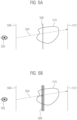
- Figs 5A and 5B schematically illustrate the use of a conventional (e.g., sharp) clip plane 508 versus a smoothed clip plane 509 according to the invention, respectively.
- the reference signs 506 and 512 denote the conventional near and far clip planes (briefly also denoted as near clip plane and far clip plane), respectively.
- the near and far clip planes may denote the front and rear boundaries of the volumetric data set, respectively, e.g., as viewed by an observer 502.
- an exemplary viewing ray is depicted, which passes through an anatomical structure 510, and/or an organ 510, within which a hidden structure is to be made visible (and/or rendered) by means of a conventional manually set (e.g., sharp) clip plane 508 in Fig. 5A , or by means of the inventive smoothed clip plane 509 in Fig. 5B , which is determined by optimizing an objective function (and/or by a computing algorithm, in particular comprising the DR algorithm).
- a viewing ray 504 traversing the anatomical structure 510 may start at the near clip plane 506 and stops when the accumulated alpha (and/or the accumulated opacity) reaches a (in particular upper) threshold, a clip plane 508; 509 for rendering a hidden structure is reached, or the far clip plane 512 is reached.
- alpha may comprise values between 0 and 1 for full transparency and full opacity, respectively.
- the viewing ray 504 may, e.g., stop is alpha exceeds a value of 0.9.
- a clipping plane e.g., the clip plane 508 or 509
- a clipping plane 508 or 509 may be used to make everything in front of it transparent. Therefore, it need not be used to stop the ray 504 traversal.
- the viewing ray 504 does not need to stop at the clip plane 508; 509.
- V be a 3D volume with scalar densities values, ⁇ an absorption function that maps the scalar densities values to opacities and C a function that maps the scalar values to colors.
- An image can be generated by computing the light accumulation along view rays r(t) (e.g., as depicted as reference sign 504 in Fig. 5A ) parameterized from the near plane a (e.g., as depicted as reference sign 506 in Fig. 5A ) and to the far plane b (e.g., as depicted as reference sign 512 in Fig. 5A ).
- a smooth clipping is used to remove the discontinuities intrinsic to visibilities changes, modulating the clipping, e.g., with a Gaussian function, as schematically shown by the smoothed clip plane at reference sign 509 in Fig. 5B .
- the inventive equation then becomes: ⁇ a b h ( V r t e ⁇ ⁇ a t ⁇ r u g r u du dt .
- the differentiable renderer can be used to estimate the location (e.g., position, and/or orientation) of the clip planes 509 to optimize an objective function, in particular a (e.g., given) loss function.
- a loss function may be formulated as the image difference between the rendered medical image 401 and the reference image (or target image) 408.
- the simplest loss function may, e.g., be a mean square difference (and/or MSE) between the pixel values of the two images 401; 408.
- More complicated loss functions may, e.g., include image registration, structural similarities (and/or SSIM), and/or feature extraction.
- Image registration may for example be used to map the target image (and/or reference image) into the rendered image before the loss function is computed, and/or before a value of the loss function is determined.
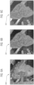
- exemplary medical images of a patient's left kidney from a CT scan are shown in Figs. 6A, 6B and 6C .
- the medical image of the left kidney is shown without clip plane.
- a reference image 301 is shown, e.g., based on a previous conventional manual selection of a sharp clip plane.
- the medical image 401 with smoothed clip plane also denoted as soft clip plane according to the inventive technique is displayed.
- the medical image 401 in Fig. 6C based on the inventive technique is only very slightly more diffuse (and/or has outlines only very slightly softened, and/or blurred) than the reference image 301 in Fig. 6B .
- the discernible hidden structure shown in the rendered medical image at reference sign 401 in Fig. 6C comprises the internal structures (e.g., thickness of the renal cortex, renal medulla, renal papilla, renal pyramids, renal columns) of the left kidney as discernible in the reference image 301 in Fig. 6B .
- exemplary medical images of a patient's left hip are shown in Figs. 7A, 7B and 7C .
- Fig. 7A the medical image of the left hip is shown without clip plane.
- Fig. 7B a reference image 301 is shown, e.g., based on a previous conventional manual selection of a sharp clip plane.
- Fig. 7C the medical image 401 with smoothed clip plane (also denoted as soft clip plane) according to the inventive technique is displayed.
- the hip images of Figs. 7A, 7B and 7C may be based on a CT scan, and/or an MRI scan.
- the medical image 401 in Fig. 7C based on the inventive technique is only very slightly more diffuse (and/or has outlines only very slightly softened, and/or blurred) than the reference image 301 in Fig. 7B .
- a brightness (and/or color) corresponding to a density of the bone structures in Figs. 7C and 7B may be identical, up to a slight softening of outlines (and/or boundaries between different brightnesses) in Fig. 7C .
- a compact bone (and/or high density of the bone structure) may correspond to a white region, and/or a very spongy bone (and/or low density of the bone structure) may correspond to a dark (e.g., brown in a colored image) region in the images 401; 301.
- the rendered medical image 401 with the inventive smoothed clipping (also denoted as soft clipping) in Fig. 6C or 7C closely matches a reference image 301 rendered with the conventional (e.g., sharp) clipping in Fig. 6B or 7B , respectively.
- Figs. 8A and 8B exemplarily illustrate the difference and/or loss function (e.g., as MSE) between the medical image 401 obtained using the inventive technique and the reference image 301 using conventional, in particular manual, clipping for the left kidney of Figs. 6C and 6B and the left hip of Figs. 7C and 7B , respectively.
- MSE difference and/or loss function
- Figs. 8A and 8B The main difference in Figs. 8A and 8B between the images 401; 301 is that when the smoothed clip plane (also denoted as soft clip plane) is used, the rendered image appears a bit less sharp.
- contours of the left kidney and the left hip which are sharp in the reference images 301 of Figs. 6B and 7B , respectively, show a slight difference from the smoothed contours of the medical images 401 of Fig. 6C and 7C , respectively.
- Fig. 9 shows another illustrative example, in an illustration from a medical book serves as reference image 408.
- the reference image 408 may comprise a plethora of reference structures (e.g., acetabulum, fibrous capsule, cavity of joint, synovial membranes, cartilage, head of femur, ligament of head of femur, synovial membranes, transverse ligament of acetabulum, fibrous capsule, zona orbicularis, and/or pubofemoral ligament, in particular as described in the context of Fig. 4B ).
- reference structures e.g., acetabulum, fibrous capsule, cavity of joint, synovial membranes, cartilage, head of femur, ligament of head of femur, synovial membranes, transverse ligament of acetabulum, fibrous capsule, zona orbicularis, and/or pubofemoral ligament, in particular as described in the context of Fig. 4B ).
- the inventive technique provides a method for rendering a hidden structure of a volumetric data set when rendering a medical image based on the volumetric data set received from a medical scanner.
- a reference information indicative of a parameter for a (in particular smoothed, and/or soft) clip plane is received for rendering the hidden structure within the medical image.
- a DR algorithm is applied on the received volumetric data set, which comprises determining a light accumulation along a viewing ray.
- the (in particular smoothed, and/or soft) clip plane is approximated by including a smooth approximation to a Dirac delta distribution, which depends on the parameter comprised in the received reference information, in the determining of the light accumulation along the viewing ray.
- the parameter for the (in particular smoothed, and/or soft) clip plane is optimized by optimizing an objective function.
- the medical image with the hidden structure visible is output for final rendering, and/or for display.
- a slight (and/or somewhat) softening of clipping areas e.g., due to a Gaussian function removing the discontinuities of conventional (e.g., sharp) clip planes, and/or automatic 3D rendering with clipping may be considered as characteristic for the inventive technique.
Landscapes
- Engineering & Computer Science (AREA)
- Physics & Mathematics (AREA)
- General Physics & Mathematics (AREA)
- Theoretical Computer Science (AREA)
- Computer Graphics (AREA)
- Computer Hardware Design (AREA)
- General Engineering & Computer Science (AREA)
- Software Systems (AREA)
- Geometry (AREA)
- Computer Vision & Pattern Recognition (AREA)
- Apparatus For Radiation Diagnosis (AREA)
- Magnetic Resonance Imaging Apparatus (AREA)
Abstract
Description
- Clipping in the context of volume rendering is a method of specifying which regions of the volume should be rendered. In medical visualization, clipping techniques are essential due to the complexity of the human anatomy. Clipping is used for exploring the inner structures of the data that would otherwise be obstructed for the viewer.
- For instance,
Figs. 3A and 3B show a rendered image of a CT study (also denoted as CT scan) of a patient'sspine 304 after surgery without and with a clip plane, respectively. Thescrews 302; 302' are (at least partially) hidden for the camera by thebone structures 304 as depicted in theimage 300 inFig. 3A , and they become visible only once a clip plane is added, and/or activated, at the right location with the precise orientation, as exemplified by theimage 301 inFig. 3B . - Estimating the optimal position and orientation for clip planes to illustrate or highlight a particular condition is a time-consuming task. However, most imaging software platforms, support clip planes and crop boxes as interactive volume clipping mechanisms.
- Differentiable renderers have been used in the past to tackle problems without introducing discontinuities, such as estimating optimal camera viewpoints or transfer functions to approximate a reference image. However, no use of differentiable renderers to estimate the position and orientation of clip planes has been described, as the presence of clip planes introduces discontinuities, making the rendering problem non differentiable.
- Differentiable volume rendering algorithms have gained a lot of attention in recent years due to their ability to learn input parameters to render a scene that can optimize an objective function. These algorithms can be designed, for example, to create a rendering that closely matches a reference image, or to find the camera parameters that provide the best view for a particular scene.
- A number of differentiable renders have been proposed to solve this inverse problem. Among them, Li et al. [Li18] present a differentiable renderer for triangular meshes overcoming the problem of geometric discontinuities and occlusions using an edge sampling approach. At the edges of objects, both sides, the background and the foreground of the edge, are sampled, and contributions for both sides are used. In [Lo19], the authors proposed an approximate algorithm for triangle meshes that avoids edge sampling through reparameterization converting boundary integrals to area integrals. However, the approach based on meshes cannot be directly applied to the case of volume rendering.
- Unlike the work of [Li18] and [Lo19] that focus of meshes, Weiss et al. [Weiss22] present a differentiable volume renderer. They optimize the continuous parameters of the rendering process and describe some practical applications. In particular, Weiss et al. use the differentiable renderer to find optimal camera parameters to maximize image entropy or to determine the transfer function that best match a reference image.
- However, the work of Weiss et al. cannot be straightforwardly or directly applied to estimate the location, position, and/or orientation of clip planes, clip surfaces or crop boxes, as the presence of clip planes, clip surfaces or crop boxes introduces discontinuities, making the rendering process non differentiable.
- Optimizing locations / positions, and/or orientations of clip planes, clip surfaces and crop boxes is therefore conventionally performed manually and in a highly time-consuming manner, preventing any use in real-time applications, e.g., for surgical guidance, validation (also denoted as verification, checkup, and/or examining) of a performed surgical procedure, and/or diagnostic purposes. Moreover, efficiently optimizing locations / positions, and/or orientations of clip planes, clip surfaces and crop boxes conventionally requires extensive training and experience by the user (e.g., a medical practitioner).
- It is therefore an object of the present invention to provide an efficient (e.g., in terms of time and/or computing resources) solution for incorporating the differentiable rendering of hidden structures within medical images. Alternatively or in addition, an object of the present invention is to provide a technique for incorporating clip planes, clip surfaces, and/or crop boxes in differentiable (e.g., volume) rendering of medical data sets, in particular while preserving all the advantages of differentiable rendering in relation to continuous rendering parameters such as camera, transfer function, lighting, opacity and/or color.
- This object is solved by a method for rendering a hidden structure of a volumetric data set when rendering a medical image based on the volumetric data set, by a computing device, by a system comprising the computing device, by a computer program (also denoted as computer program product), and by a computer-readable medium according to the appended independent claims. Advantageous aspects, features and embodiments are described in the dependent claims and in the following description together with advantages.
- In the following, the solution according to the invention is described with respect to the claimed method as well as with respect to the claimed device. Features, advantages or alternative embodiments herein can be assigned to the other claimed objects (e.g., the system, the computer program and/or a computer program product, and/or the computer-readable medium), and vice versa. In other words, claims for the device and/or system can be improved with features described or claimed in the context of the method. In this case, the functional features of the method are embodied by structural units (and/or modules) of the device and/or system, and vice versa, respectively.
- As to a method aspect, a (in particular computer-implemented) method for rendering a hidden structure of a volumetric data set when rendering a medical image based on the volumetric data set is provided. The volumetric data set is received from a medical scanner. The method comprising a step of receiving the volumetric data set from the medical scanner. The method further comprises a step of receiving a reference information indicative of (e.g., an initial value of) at least one parameter for a clip plane within a medical image for rendering the hidden structure comprised in the received volumetric data set. The method further comprises a step of applying a differentiable rendering (DR) algorithm on the received volumetric data set for rendering the medical image with the hidden structure. Applying the DR algorithm comprises determining a light accumulation along a viewing ray. The clip plane is approximated by including a smooth approximation to a Dirac delta distribution in the determining of the light accumulation along the viewing ray. The smooth approximation to the Dirac delta distribution depends on the (e.g., initial value of the) at least one parameter comprised in the received reference information. Applying the DR algorithm further comprises optimizing the at least one parameter for the clip plane by optimizing an objective function. The method still further comprises a step of outputting, based on the applied DR algorithm, the medical image with the hidden structure. The hidden structure is visible in the medical image output for final rendering, and/or for display.
- By the inventive technique, a discontinuity due to the clip plane, which would impede the use of DR, can be avoided. Alternatively or in addition, by the inventive technique, an optimal position of a clip plane for medical purposes can be automatically determined, leading to time saving from receiving the volumetric data set from the medical scanner to performing the final rendering (also denoted as output for display, or displaying). E.g., a positioning of one or more implants, in particular after a surgical procedure in which the implants were placed, can be controlled by the inventive technique in a timely manner. Alternatively or in addition, by the inventive technique, a diagnosis of a lesion (e.g., a tumor and/or a torn ligament) within an organ and/or anatomical structure (e.g., within the liver, a kidney, a joint and/or a ligament) can be promptly (also: timely) performed, and/or improved. E.g., the medical image with optimized clip plane as well as optimized further (in particular continuous) rendering parameters can be made available such that a separate appointment date (e.g., on a different day) for a patient for reviewing a diagnostic result (and/or medical analysis) of the acquisition of the volumetric data set by means of the medical scanner can be avoided.
- The volumetric data set may also be denoted as three-dimensional data set. Alternatively or in addition, the volumetric data set may be received from a medical scanner comprising a (e.g., predetermined) imaging modality. The imaging modality may comprise computed tomography (CT), magnetic resonance imaging (MRI), ultrasound (US), positron emission tomography (PET), and/or single-photon emission computed tomography (SPECT).
- Alternatively or in addition, the volumetric data set may comprise a (e.g., cine) series of three-dimensional data sets over a time interval. Further alternatively or in addition, the volumetric data set may vary over time (e.g., over a time period of acquisition from the medical scanner).
- The structure(s) of interest may be occluded (also: concealed, obscured, and/or hidden) behind an anatomical structure, an organ's surface and/or behind a further structure, in particular comprising an implant or other synthetical structures, in the volumetric data set, when rendered without applying any clip plane. By applying the clip plane (also: clipping plane), the occluding structure may be removed from the rendered medical image. Thereby, the hidden structure may be made fully, or at least partially, visible (also: visualized, and/or shown) on the (e.g., finally rendered and/or displayed) medical image.
- The clip plane may also be denoted as clip surface, and/or clipping plane. Alternatively or in addition, the clip plane may comprise two or more components, and/or clip planes, in particular at relative non-vanishing angles. E.g., a crop box may be based, and/or may comprise, a plurality of clip planes. Alternatively or in addition, a crop box may be based, and/or may comprise one or more spatially limited (and/or finitely extended) clip planes.
- Alternatively or in addition, in general a clip plane may be used to make everything in front of it transparent. Further alternatively or in addition, by the change of transparency in front of the clip plane, usually a viewing ray traversal does not need to stop at the clip plane.
- The hidden structure may comprise an implant, a synthetical structure and/or an anatomical structure.
- The implant may comprise a stent, a screw, and/or an artificial joint, e.g., an artificial hip. Alternatively or in addition, the implant may comprise a sensory implant, a neurological implant, and/or a cardiovascular medical device (e.g., a cardiac stimulator, and/or pacemaker).
- The anatomical structure may comprise an abnormality (also denoted as pathology), a lesion, a tumor, and/or a (e.g., at least partially torn) ligament.
- The at least one parameter for the clip plane may comprise a position, and/or an orientation, of the clip plane.
- The reference information may comprise a reference image, e.g., from a database for a predetermined type of (in particular anatomical) structures, and/or organs, comprised in the volumetric data set. Alternatively or in addition, the reference information may comprise a position information for the clip plane, e.g., based on a segmentation of (in particular anatomical) structures, and/or organs, comprised in the volumetric data set. E.g., the at least one parameter may be indicative of applying the clip plane approximately centrally within an organ.
- The DR may also be denoted as differentiable volume rendering (DVR). Alternatively or in addition, the inventive DR algorithm may extend the functionalities, and/or workings, of the DVRs of [Weiss22].
- Applying the DR may comprise applying a rendering algorithm. The rendering algorithm may comprise raycasting, and/or (e.g., Monte Carlo) path tracing.
- A (e.g., sharp) clip plane may have a vanishing thickness, and/or may lead to a discontinuity in the volumetric data, and/or may preclude (and/or make impossible) the use of the DR algorithm. Alternatively or in addition, a clip plane may be represented by the Dirac delta distribution (also denoted as δ-distribution, Dirac delta function, and/or δ-function). At the location (e.g., position, and/or orientation) of the clip plane, the Dirac delta distribution may be non-vanishing, and/or at any location (e.g., position, and/or orientation) outside the clip plane, the Dirac delta distribution may be vanishing.
- The (e.g., sharp) clip plane may be approximated by a smoothed clip plane (which may also be denoted as soft clip plane). The smoothed clip plane may be represented by a smooth function (e.g., a Gaussian function) approximating the Dirac delta distribution with non-vanishing values within a non-vanishing thickness of the (e.g., smoothed) clip plane. The smooth function (e.g., the Gaussian function) may rapidly approximate a vanishing value outside the thickness of the (e.g., smoothed) clip plane.
- By the smoothing of the clip plane, the volumetric data may remain continuous, and/or the DR algorithm may remain applicable. In particular, further (e.g., continuous) rendering parameters may still be optimized by means of the DR algorithm.
- (E.g., iteratively) applying the DR algorithm may comprise optimizing the at least one parameter for the clip plane (briefly also denoted as clip plane parameter), in particular the position and/or orientation of the clip plane, by optimizing an objective function.
- The objective function may comprise a loss function, in particular for a reference image as the reference information. The loss function may be optimized by minimizing the difference between (briefly also denoted as: matching) the reference image and the medical image with the visibly rendered hidden structure, or at least parts thereof. Alternatively or in addition, optimizing the loss function may comprise minimizing a mean square difference (also denoted as mean square error, MSE) between pixel values, maximizing structural similarities (also denoted as structural similarity index measure, SSIM), and/or alignment of feature extraction.
- Image registration may be used, e.g., to match the medical image to a previous scan. Alternatively or in addition, image registration is not necessarily used for the image comparison. Further alternatively or in addition, image registration may, e.g., be used to map the target image (and/or reference image) into the rendered image before the loss function is computed, and/or before a value of the loss function is determined.
- Alternatively or in addition, (e.g., optimizing) the objective function may comprise (e.g., maximizing) an image entropy, in particular for the reference information comprising a position information relative to an (e.g., anatomical) structure, and/or organ, comprised in the volumetric data set. E.g., the at least one parameter may specify to initially set the clip plane centrally, e.g., based on a segmentation and/or classification, within an organ.
- The optimizing of the objective function may comprise a combination of (e.g., minimizing) one or more loss functions, and/or (e.g., maximizing) image entropy.
- The applying of the DR algorithm may be iterative. E.g., the received at least one parameter may comprise, and/or may determine, an initial value of the one or more clip plane parameters. The optimizing of the objective function may comprise varying the one or more clip plane parameters.
- The optimization of the objective function, and/or of the at least one parameter for the clip plane, may be gradient-based.
- The inventive technique may be applied to more than one clip plane within a volumetric data set. Alternatively or in addition, by applying more than one clip plane for the rendering of the medical image, more than one hidden structure (e.g., several implants) may be rendered visible. Alternatively or in addition, the more than one clip plane may be applied at relative non-vanishing angles. E.g., by applying three clip planes at approximately right angles (90°) to each other, a pie-slice-shaped section (and/or wedge) of a human skull may be cut out of the medical image in order to provide a view on the brain.
- Besides the at least one parameter for the clip plane, input parameters to the DR algorithm may comprise a camera parameter (also denoted as view parameter), and/or a transfer function (TF). By the TF, voxel values may be assigned to color, and/or opacity, of a pixel of the medical image.
- The hidden structure may comprise an implant, in particular a stent, a screw, and/or an artificial joint, in particular an artificial hip. Alternatively or in addition, the hidden structure may comprise an anatomical structure, in particular a lesion, a tumor, and/or a ligament.
- The received reference information may comprise a medical reference image.
- The medical reference image (briefly: reference image) may comprise a, e.g., previously stored medical image, in particular comprising a manually set clip plane. Alternatively or in addition, the medical reference image may comprise a synthetic image, and/or a painted (also: sketched, and/or drawn) image. Alternatively or in addition, medical images may be retrieved from a medical journal and/or a book, from a medical image database and/or a medical image library, e.g., provided by an medical expert.
- The objective function may comprise a loss function depending on the medical reference image. Optimizing the loss function may comprise minimizing, and/or maximizing, the loss function.
- The loss function may comprise the difference between the reference image and the medical image with the visibly rendered hidden structure. Alternatively or in addition, the loss function may comprise a mean square difference (and/or MSE) between pixel values. Further alternatively or in addition, the loss function may be based on structural similarities (and/or a SSIM), and/or on feature extraction.
- The received reference information may comprise a (e.g., initial value of a) position relative to an anatomical structure, and/or relative to an organ.
- The (in particular initial value of the) position relative to the anatomical structure, and/or relative to the organ, may be obtained by performing a segmentation, and/or a classification of the anatomical structure, and/or the organ, captured in the volumetric data set. The (in particular initial value of the) position may, e.g., comprise a central location (e.g., position, and/or orientation) within the segmented, and/or classified, anatomical structure, and/or organ.
- Alternatively or in addition, the objective function may comprise an image entropy. Optimizing the objective function may comprise maximizing the image entropy.
- By maximizing the image entropy, structures, in particular lesions, within the volumetric data set may be rendered visible (also: visualized, and/or made visible). E.g., a lesion may correspond to, and/or may produce, an inhomogeneity in the medical image, which can be rendered visible by using the image entropy, e.g., as a measure for the (in particular image) inhomogeneity.
- Maximizing the image entropy may be combinable with providing the initial value of the at least one parameter for the clip plane (also: clip plane parameter) by means of a reference image.
- The objective function used for optimizing the at least one parameter may be determined (and/or selected) based on the received reference information.
- Alternatively or in addition, if a reference image is provided, different image quality metrics may be used as loss functions. Further alternatively or in addition, if no reference image is provided, a non-reference loss function, and/or non-reference metric, needs to be used. Information entropy may be an example of a non-reference loss function.
- The at least one parameter of the clip plane may comprise a position, and/or an orientation, of the clip plane within the volumetric data set.
- The smooth approximation to the Dirac delta distribution may comprises a Gaussian function. Alternatively or in addition, the smooth approximation to the Dirac delta distribution may also be denoted as nascent delta function.
- For the purpose of computer graphics, the smooth approximation to Dirac's delta distribution (in particular the Gaussian function) may be discretized per voxel, and/or per pixel.
- The light accumulation may be determined by means of raycasting, (e.g., Monte Carlo) path tracing, half-angle slicing, and/or interactive volume lighting, IVL.
- The light accumulation may comprise local illumination effects (e.g., light attenuating from voxel to voxel due to the voxel's opacity, and/or from pixel to pixel due to the pixel's opacity), and/or global illumination effects (e.g., due to light scattering).
- The at least one parameter of a clip plane may comprise two or more parameters, in particular of two or more clip planes.
- The two or more clip planes may be non-parallel, and/or at non-vanishing angles. Thereby, a slice (and/or wedge) may be cut out of a rendered (e.g., anatomical) structure.
- The medical scanner may be selected from the group of a CT scanner, an MRI scanner, a US scanner, a PET scanner, and/or a SPECT scanner.
- As to a device aspect, a computing device for rendering a hidden structure of a volumetric data set when rendering a medical image based on the volumetric data set is provided. The volumetric data set is received from a medical scanner. The computing device comprises a volumetric data set receiving interface configured for receiving a volumetric data set from a medical scanner. The computing device further comprises a reference information receiving interface configured for receiving a reference information indicative of (e.g., an initial value of) at least one parameter for a clip plane within a medical image for rendering the hidden structure comprised in the received volumetric data set. The computing device further comprises a processing module (e.g., a CPU, and/or GPU) configured for applying a DR algorithm on the received volumetric data set for rendering the medical image with the hidden structure. Applying the DR algorithm comprises determining a light accumulation along a viewing ray. The clip plane is approximated by including a smooth approximation to a Dirac delta distribution in the determining of the light accumulation along the viewing ray. The smooth approximation to the Dirac delta distribution depends on the (e.g., initial value of the) at least one parameter comprised in the received reference information. Applying the DR algorithm further comprises optimizing the at least one parameter for the clip plane by optimizing an objective function. The computing device still further comprises an outputting interface configured for outputting, based on the applied DR algorithm, the medical image with the hidden structure. The hidden structure is visible in the medical image output for final rendering, and/or for display.
- The computing device may be configured to perform the method according to the method aspect. Alternatively or in addition, the computing device may comprise any feature disclosed in the context of the method according to the method aspect.
- As to a system aspect, a system for rendering a hidden structure of a volumetric data set when rendering a medical image based on the volumetric data set is provided. The volumetric data set is received from a medical scanner. The system comprises one or more medical scanners configured for providing a volumetric data set. The system further comprises a computing device according to the device aspect. The volumetric data set receiving interface of the computing device is configured for receiving the volumetric data set from any one of the one or more medical scanners. The system still further comprises a display device (briefly also: display) configured for receiving a medical image with a hidden structure from the outputting interface of the computing device. The display device is further configured for displaying, and/or final rendering, the received medical image with the hidden structure.
- As to a further aspect, a computer program comprising program elements which induce a computing device to carry out the steps of the method, according to the method aspect, for rendering a hidden structure of a volumetric data set when rendering a medical image based on the volumetric data set is provided. The steps of the method are carried out when the program elements are loaded into a memory of the computing device.
- As to a still further aspect, a computer-readable medium, on which program elements are stored that can be read and executed by a computing device in order to perform steps of the method, according to the method aspect, for rendering a hidden structure of a volumetric data set when rendering a medical image based on the volumetric data set is provided. The steps of the method are performed when the program elements are executed by the computing device.
- The properties, features and advantages of this invention described above, as well as the manner they are achieved, become clearer and more understandable in the light of the following description and embodiments, which will be described in more detail in the context of the drawings. This following description does not limit the invention on the contained embodiments. Same components or parts can be labeled with the same reference signs in different figures. In general, the figures are not for scale.
- It shall be understood that a preferred embodiment of the present invention can also be any combination of the dependent claims or above embodiments with the respective independent claim.
- These and other aspects of the invention will be apparent from and elucidated with reference to the embodiments described hereinafter.
-
- Fig. 1
- is a flow chart of a method for rendering a hidden structure of a volumetric data set when rendering a medical image based on the volumetric data set according to a preferred embodiment of the present invention;
- Fig. 2
- is an overview of the structure and architecture of a computing device for rendering a hidden structure of a volumetric data set when rendering a medical image based on the volumetric data set according to a preferred embodiment of the present invention, wherein the computing device may be configured to perform the method of
Fig. 1 ; - Figs. 3A and 3B
- show an example of a rendered medical image based on a CT scan without and with a clip plane, respectively, with screws, as examples of hidden structures, surgically inserted into a patient's spine and rendered visible in the medical image with suitable position of the clip plane in
Fig. 3B ; - Figs. 4A and 4B
- schematically illustrate the applying of a differentiable rendering (DR) algorithm according to the method of
Fig. 1 , inFig. 4A without a reference image and, e.g., maximizing of an image entropy, and inFig. 4B with a reference image and optimizing a loss function involving the reference image; - Figs. 5A and 5B
- schematically illustrate the use of a conventional sharp clip plane and an inventive smoothed clip plane, respectively;
- Figs. 6A, 6B and 6C
- show examples of rendering a left kidney without clip plane in
Fig. 6A and with inventive smoothed clip plane inFig 6C , where the position of the smoothed clip plane is determined from the reference image inFig. 6B , e.g., in which a sharp clip plane had previously been selected manually; - Figs. 7A, 7B and 7C
- show examples of rendering a left hip joint without clip plane in
Fig. 7A and with inventive smoothed clip plane inFig 7C , where the position of the smoothed clip plane is determined from the reference image inFig. 7B , e.g., in which a sharp clip plane had previously been selected manually; - Figs. 8A and 8B
- show loss functions for the rendering of the left kidney and left hip joint with inventive clip planes according to
Figs. 6C and7C relative to the conventional, in particular manually selected, reference images ofFig. 6B and7B , respectively; and - Fig. 9
- shows an example of a reference image as reference information based on an illustration in medical literature.
- Any reference signs in the claims should not be construed as limiting the scope.
-
Fig. 1 schematically illustrates an exemplary embodiment of a computer-implemented method for rendering a hidden structure of a volumetric data set when rendering a medical image based on the volumetric data set, which is received from a medical scanner. The method is generally referred to by thereference sign 100. - The
method 100 comprises a step S102 of receiving the volumetric data set from the medical scanner. - The
method 100 further comprises a step S104 of receiving a reference information indicative of at least one parameter for a clip plane within a medical image for rendering the hidden structure comprised in the received S102 volumetric data set. - The
method 100 further comprises a step S106 of applying a differentiable rendering (DR) algorithm on the received S102 volumetric data set for rendering the medical image with the hidden structure. Applying S106 the DR algorithm comprises determining a light accumulation along a viewing ray. The clip plane is approximated by including a smooth approximation to a Dirac delta distribution in the determining of the light accumulation along the viewing ray. The smooth approximation to the Dirac delta distribution depends on the at least one parameter comprised in the received S104 reference information. Applying S106 the DR algorithm further comprises optimizing the at least one parameter for the clip plane by optimizing an objective function. - The
method 100 still further comprises a step S108 of outputting, based on the applied S106 DR algorithm, the medical image with the hidden structure. The hidden structure is visible in the medical image outputted for final rendering, and/or for display. -
Fig. 2 schematically illustrates an exemplary embodiment of a computing device for rendering a hidden structure of a volumetric data set when rendering a medical image based on the volumetric data set, which is received from a medical scanner. The computing device is generally referred to by thereference sign 200. - The
computing device 200 comprises a volumetric dataset receiving interface 202 configured for receiving a volumetric data set from a medical scanner. - The
computing device 200 further comprises a referenceinformation receiving interface 204 configured for receiving a reference information indicative of at least one parameter for a clip plane within a medical image for rendering the hidden structure comprised in the received volumetric data set. - The
computing device 200 further comprises aprocessing module 206 configured for applying a DR algorithm on the received volumetric data set for rendering the medical image with the hidden structure. Applying the DR algorithm comprises determining a light accumulation along a viewing ray. The clip plane is approximated by including a smooth approximation to a Dirac delta distribution in the determining of the light accumulation along the viewing ray. The smooth approximation to the Dirac delta distribution depends on the at least one parameter comprised in the received reference information. Applying the DR algorithm further comprises optimizing the at least one parameter for the clip plane by optimizing an objective function. - The
computing device 200 still further comprises an outputtinginterface 208 configured for outputting, based on the applied DR algorithm, the medical image with the hidden structure. The hidden structure is visible in the medical image outputted for final rendering, and/or for display. - The
processing module 206 may be embodied by a processor and/or a central processing unit (CPU), and/or a graphics processing unit (GPU). - Optionally, the
computing device 200 may comprise amemory 210. - Any one of the volumetric data
set receiving interface 202, the referenceinformation receiving interface 204, and/or the outputtinginterface 208 may be comprised in a common (e.g., input-output)interface 212. - The
computing device 200 may be configured for performing themethod 100. - A system for rendering a hidden structure of a volumetric data set when rendering a medical image based on the volumetric data set, which is received from a medical scanner, may comprise one or more medical scanners for acquiring the volumetric data set, a computing device (e.g., the computing device 200) for performing the
method 100, and a display device. - The display device (briefly also denoted as display) may comprise a monitor and/or screen, and/or an extended reality (XR) device, in particular an XR headset. XR may be an umbrella term for augmented reality (AR), and/or virtual reality (VR). The XR device may comprise a head-mounted display (HMD), and/or a head-up display (HUD).
- The inventive technique (e.g., comprising the
method 100, thecomputing device 200, and/or the system) may alternatively be denoted as technique for inverse volume rendering with clipping. - By the inventive technique, a differentiable renderer (e.g., in performing the method step S106, and/or embodied by the processing module 206) is used to predict one or more optimal clip plane parameters to optimize an objective function. Depending on the application (e.g., for diagnostic purposes, and/or for post-surgical verification), the clip can serve to describe the presence of lesions, and/or the viewpoint to best visualize stents, screws, artificial joints, and/or any further implant. Alternatively or in addition, the inventive technique can be used to match a reference image from a medical database or a medical illustration.
- Rendering a three-dimensional (3D) scene (e.g., corresponding to, and/or encoded by, a volumetric data set) may comprise the process of generating a two-dimensional (2D) image I by simulating the interaction of the light with the objects in the scene (and/or comprised in the volumetric data set).
- Alternatively or in addition, rendering may be described as a function f that takes input parameters x and produces a rendered medical image I = f(x). As shown in
Figs. 4A and4B , differentiable renderers atreference sign 404 aim at solving the inverse problem, that is, predicting the scene parameters x atreference sign 402 from a particular medical image I, as exemplified atreference sign 401. DR algorithms work by propagating derivatives with respect to the input parameters x to maximize a loss function z(I), usually by some form of gradient-based optimization technique, as indicated atreference sign 406. -
Fig. 4A schematically illustrates adifferentiable renderer 404 designed to learn input parameters x atreference sign 402 based on a general loss function z(I) atreference sign 406. - The medical image I at
reference sign 401 inFig. 4A provides an example of a cross section of (e.g., patient's) left kidney rendered by using a (e.g., smoothed) clip plane. The clip plane for the rendered medical image I atreference sign 401 inFig. 4A may, e.g., be obtained by providing a position (e.g., approximately centrally within the left kidney) as reference information for the clip plane parameter. Alternatively or in addition, the location (e.g., position, and/or orientation) of the clip plane in the medical image I atreference sign 401 ofFig. 4A may be determined based on maximizing image entropy (e.g., as the objective function z(I) atreference sign 406 inFig. 4A ). The hidden structure shown in the rendered medical image I atreference sign 401 inFig. 4A comprises the internal structures (e.g., thickness of the renal cortex, renal medulla, renal papilla, renal pyramids, renal columns) of the left kidney. -
Fig. 4B schematically illustrates adifferentiable renderer 404 with loss function z(I) atreference sign 406 designed to learn input parameters x atreference sign 402 to match a reference image R (also denoted as target image) as exemplified atreference signs - The medical image I at
reference sign 401 ofFig. 4B provides an example of a cross section of a left hip joint using a (e.g., smoothed) clip plane. The clip plane for the rendered medical image I atreference sign 401 inFig. 4B may, e.g., be obtained by providing a location (e.g., position and/or orientation) of the clip plane in terms of thereference image 408 as the reference information for the clip plane parameter. Alternatively or in addition, the location (e.g., position, and/or orientation) of the clip plane in the medical image I atreference sign 401 ofFig. 4B may be determined based on a MSE, SSIM, and/or feature extraction (e.g., as the objective function z(I) atreference sign 406 inFig. 4B ). - In
Fig. 4B , in thereference image 408 relevant hip structures may be visible (e.g., acetabulum, fibrous capsule, cavity of joint, synovial membranes, cartilage, head of femur, ligament of head of femur, synovial membranes, transverse ligament of acetabulum, fibrous capsule, zona orbicularis, and/or pubofemoral ligament). - A 3D scene (e.g., as encoded by the volumetric data set) usually comprises geometrical models, materials, camera properties, light sources, and/or other input parameters to the rendering system.
- In medical visualization (e.g., according to the inventive technique), the scene may comprise at least a volume (e.g., from a CT, MRI, and/or PET scan) together with a transfer function that maps voxel values to colors and opacities. Different direct volume rendering algorithms have been described in the literature, including raycasting algorithms and recently (e.g., Monte Carlo) path tracing techniques that simulate the physics of light along light paths for each pixel to generate photorealistic depictions of medical data.
- Fortunately, the conventional volume rendering process is differentiable with respect to most scene parameters, as the gradients can be estimated and propagated. However, this is not the case when clipping objects (e.g., clip planes, clip surfaces, and/or crop boxes) are present in the 3D scene (e.g., applied to the volumetric data set). The introduction of clip planes (also denoted as clipping planes or clipping surfaces), for example, introduces discontinuities, making the rendering process not differentiable. The inventive technique overcomes this deficiency by incorporating clip planes (and/or clipping surfaces) to the rendering process without introducing discontinuities.
-
Figs 5A and 5B schematically illustrate the use of a conventional (e.g., sharp)clip plane 508 versus a smoothedclip plane 509 according to the invention, respectively. - The reference signs 506 and 512 denote the conventional near and far clip planes (briefly also denoted as near clip plane and far clip plane), respectively. The near and far clip planes may denote the front and rear boundaries of the volumetric data set, respectively, e.g., as viewed by an
observer 502. Atreference sign 504, an exemplary viewing ray is depicted, which passes through ananatomical structure 510, and/or anorgan 510, within which a hidden structure is to be made visible (and/or rendered) by means of a conventional manually set (e.g., sharp)clip plane 508 inFig. 5A , or by means of the inventive smoothedclip plane 509 inFig. 5B , which is determined by optimizing an objective function (and/or by a computing algorithm, in particular comprising the DR algorithm). - In general, a
viewing ray 504 traversing the anatomical structure 510 (and/or organ 510) may start at thenear clip plane 506 and stops when the accumulated alpha (and/or the accumulated opacity) reaches a (in particular upper) threshold, aclip plane 508; 509 for rendering a hidden structure is reached, or thefar clip plane 512 is reached. Herein, alpha may comprise values between 0 and 1 for full transparency and full opacity, respectively. Theviewing ray 504 may, e.g., stop is alpha exceeds a value of 0.9. - Alternatively or in addition, in general a clipping plane (e.g., the
clip plane 508 or 509) may be used to make everything in front of it transparent. Therefore, it need not be used to stop theray 504 traversal. Alternatively or in addition, theviewing ray 504 does not need to stop at theclip plane 508; 509. - Let V be a 3D volume with scalar densities values, τ an absorption function that maps the scalar densities values to opacities and C a function that maps the scalar values to colors. An image can be generated by computing the light accumulation along view rays r(t) (e.g., as depicted as
reference sign 504 inFig. 5A ) parameterized from the near plane a (e.g., as depicted asreference sign 506 inFig. 5A ) and to the far plane b (e.g., as depicted asreference sign 512 inFig. 5A ). The light intensity equation can be written as [Weiss22]:
- According to the inventive technique, a "smooth clipping" is used to remove the discontinuities intrinsic to visibilities changes, modulating the clipping, e.g., with a Gaussian function, as schematically shown by the smoothed clip plane at
reference sign 509 inFig. 5B . - According to the inventive technique, the light intensity formulation is extended by adding a Gaussian function g(x) =

reference sign 509 inFig. 5B ). The inventive equation then becomes:
- Since the above integral cannot be solved analytically, it is often approximated by discrete ray segments, each assumed to have constant absorption and emission. The discrete transparency at sample i can be written as αi = 1 - e -ΔtτV(i)g(i), where V(i) is the density of the volume and g(i) is the Gaussian function at sample i along the viewing ray (e.g., at
reference sign 504 inFig. 5B ). - With the modification of including the Gaussian function, the same automatic (and/or computerized, and/or algorithmic) differentiation described in [Weiss] can be applied even in the presence of clip planes 509.
- Using the inventive technique, the differentiable renderer can be used to estimate the location (e.g., position, and/or orientation) of the clip planes 509 to optimize an objective function, in particular a (e.g., given) loss function. For instance, given a reference image (also denoted as target image) 408, the loss function may be formulated as the image difference between the rendered
medical image 401 and the reference image (or target image) 408. The simplest loss function may, e.g., be a mean square difference (and/or MSE) between the pixel values of the twoimages 401; 408. More complicated loss functions may, e.g., include image registration, structural similarities (and/or SSIM), and/or feature extraction. - Image registration may for example be used to map the target image (and/or reference image) into the rendered image before the loss function is computed, and/or before a value of the loss function is determined.
- Based on the inventive technique, exemplary medical images of a patient's left kidney from a CT scan are shown in
Figs. 6A, 6B and 6C . InFig. 6A , the medical image of the left kidney is shown without clip plane. InFig. 6B , areference image 301 is shown, e.g., based on a previous conventional manual selection of a sharp clip plane. InFig. 6C , themedical image 401 with smoothed clip plane (also denoted as soft clip plane) according to the inventive technique is displayed. - As visible, the
medical image 401 inFig. 6C based on the inventive technique is only very slightly more diffuse (and/or has outlines only very slightly softened, and/or blurred) than thereference image 301 inFig. 6B . E.g., the discernible hidden structure shown in the rendered medical image atreference sign 401 inFig. 6C comprises the internal structures (e.g., thickness of the renal cortex, renal medulla, renal papilla, renal pyramids, renal columns) of the left kidney as discernible in thereference image 301 inFig. 6B . - Based on the inventive technique, exemplary medical images of a patient's left hip are shown in
Figs. 7A, 7B and 7C . InFig. 7A , the medical image of the left hip is shown without clip plane. InFig. 7B , areference image 301 is shown, e.g., based on a previous conventional manual selection of a sharp clip plane. InFig. 7C , themedical image 401 with smoothed clip plane (also denoted as soft clip plane) according to the inventive technique is displayed. - The hip images of
Figs. 7A, 7B and 7C may be based on a CT scan, and/or an MRI scan. - As visible, the
medical image 401 inFig. 7C based on the inventive technique is only very slightly more diffuse (and/or has outlines only very slightly softened, and/or blurred) than thereference image 301 inFig. 7B . E.g., a brightness (and/or color) corresponding to a density of the bone structures inFigs. 7C and 7B may be identical, up to a slight softening of outlines (and/or boundaries between different brightnesses) inFig. 7C . A compact bone (and/or high density of the bone structure) may correspond to a white region, and/or a very spongy bone (and/or low density of the bone structure) may correspond to a dark (e.g., brown in a colored image) region in theimages 401; 301. - In both illustrative examples, the kidney in
Figs. 6A, 6B and 6C as well as the hip inFigs. 7A, 7B and 7C , the renderedmedical image 401 with the inventive smoothed clipping (also denoted as soft clipping) inFig. 6C or7C closely matches areference image 301 rendered with the conventional (e.g., sharp) clipping inFig. 6B or7B , respectively. -
Figs. 8A and 8B exemplarily illustrate the difference and/or loss function (e.g., as MSE) between themedical image 401 obtained using the inventive technique and thereference image 301 using conventional, in particular manual, clipping for the left kidney ofFigs. 6C and 6B and the left hip ofFigs. 7C and 7B , respectively. - The main difference in
Figs. 8A and 8B between theimages 401; 301 is that when the smoothed clip plane (also denoted as soft clip plane) is used, the rendered image appears a bit less sharp. E.g., inFigs. 8A and 8B contours of the left kidney and the left hip, which are sharp in thereference images 301 ofFigs. 6B and7B , respectively, show a slight difference from the smoothed contours of themedical images 401 ofFig. 6C and7C , respectively. - According to the inventive technique, it is possible, given an appropriate (e.g., depending on the received reference information) loss function, to estimate the rendering parameters, including one or more clip plane parameters. E.g.,
Fig. 9 shows another illustrative example, in an illustration from a medical book serves asreference image 408. - While
Fig. 9 shows a particularly simple (and/or rudimentary) example of a hip joint, thereference image 408 may comprise a plethora of reference structures (e.g., acetabulum, fibrous capsule, cavity of joint, synovial membranes, cartilage, head of femur, ligament of head of femur, synovial membranes, transverse ligament of acetabulum, fibrous capsule, zona orbicularis, and/or pubofemoral ligament, in particular as described in the context ofFig. 4B ). - The inventive technique provides a method for rendering a hidden structure of a volumetric data set when rendering a medical image based on the volumetric data set received from a medical scanner. A reference information indicative of a parameter for a (in particular smoothed, and/or soft) clip plane is received for rendering the hidden structure within the medical image. A DR algorithm is applied on the received volumetric data set, which comprises determining a light accumulation along a viewing ray. The (in particular smoothed, and/or soft) clip plane is approximated by including a smooth approximation to a Dirac delta distribution, which depends on the parameter comprised in the received reference information, in the determining of the light accumulation along the viewing ray. The parameter for the (in particular smoothed, and/or soft) clip plane is optimized by optimizing an objective function. The medical image with the hidden structure visible is output for final rendering, and/or for display.
- Despite the large number of publications on differentiable renderers, to the inventor's best knowledge, none of them have been designed to estimate parameters to optimize the location, position, and/or orientation of clip planes, and/or surfaces on the scene.
- A slight (and/or somewhat) softening of clipping areas, e.g., due to a Gaussian function removing the discontinuities of conventional (e.g., sharp) clip planes, and/or automatic 3D rendering with clipping may be considered as characteristic for the inventive technique.
- Wherever not already described explicitly, individual embodiments, or their individual aspects and features, described in relation to the drawings can be combined or exchanged with one another without limiting or widening the scope of the described invention, whenever such a combination or exchange is meaningful and in the sense of this invention. Advantages which are described with respect to a particular embodiment of present invention or with respect to a particular figure are, wherever applicable, also advantages of other embodiments of the present invention.
List of Cited Documents [Li18] Tzu-Mao Li, Miika Aittala, Frédo Durand, Jaakko Lehtinen. Differentiable Monte Carlo Ray Tracing through Edge Sampling. ACM Transactions on Graphics 37(6) (Proceedings of ACM SIGGRAPH Asia 2018) (https://people.csail.mit.edu/tzumao/diffrt/diffrt. pdf ) [Lo19] Guillaume Loubet, Nicolas Holzschuch, and Wenzel Jakob. 2019. Reparameterizing discontinuous integrands for differentiable rendering. ACM Trans. Graph. (Proc. SIGGRAPH Asia) 38, 6 (Dec. 2019). https://hal.inria.fr/hal-02497191/file/differentiable-pt-cov.pdf [Weiss22] Sebastian Weiss and Rudiger Westermann, "Differentiable Direct Volume Rendering", IEEE Transactions on Visualization and Computer Graphics, 562-572,28, 1 https://arxiv.org/pdf/2107.12672.pdf -
- 100
- Method
- S102
- Step of receiving a volumetric data set from a scanner
- S104
- Step of receiving a reference information for a parameter of a clip plane
- S106
- Step of applying a differentiable rendering (DR) algorithm
- S108
- Step of outputting
- 200
- Computing device
- 300
- Medical image without clip plane
- 301
- Medical image with sharp clip plane
- 302
- Implant
- 302'
- Hidden structure of implant
- 304
- Occluding anatomical structure
- 401
- Medical image with smooth clip plane
- 402
- One or more input parameters x
- 404
- Differentiable renderer
- 406
- Loss function
- 408
- Reference image
- 502
- Observer
- 504
- Viewing ray
- 506
- Near clip plane, e.g., as front boundary of the volumetric data set
- 508
- Sharp clip plane
- 509
- Smoothed clip plane
- 510
- Anatomical structure
- 512
- Far clip plane, e.g., as rear boundary of the volumetric data set
- 802
- Non-vanishing values of loss function of medical image with smooth clip plane versus with sharp clip plane
Claims (16)
- Computer-implemented method (100) for rendering a hidden structure of a volumetric data set when rendering a medical image based on the volumetric data set, wherein the volumetric data set is received from a medical scanner, comprising the method steps of:- Receiving (S102) a volumetric data set from a medical scanner;- Receiving (S104) a reference information (408) indicative of at least one parameter (402) for a clip plane (509) within a medical image (401) for rendering the hidden structure (302') comprised in the received (S102) volumetric data set;- Applying (S106) a differentiable rendering, DR, algorithm (404) on the received (S102) volumetric data set for rendering the medical image (401) with the hidden structure (302'), wherein applying (S106) the DR algorithm comprises determining a light accumulation along a viewing ray (504), wherein the clip plane (509) is approximated by including a smooth approximation to a Dirac delta distribution in the determining of the light accumulation along the viewing ray (504), wherein the smooth approximation to the Dirac delta distribution depends on the at least one parameter (402) comprised in the received (S104) reference information (408), and wherein applying (S106) the DR algorithm (404) further comprises optimizing the at least one parameter (402) for the clip plane (509) by optimizing an objective function (406); and- Outputting (S108), based on the applied (S106) DR algorithm (404), the medical image (401) with the hidden structure (302'), being visible for final rendering, and/or for display.
- Method (100) according to claim 1, wherein the hidden structure comprises an implant, in particular a stent, a screw, and/or an artificial hip.
- Method (100) according to any of the preceding claims, wherein the hidden structure comprises an anatomical structure, in particular a lesion, a tumor, and/or a ligament.
- Method (100) according to any of the preceding claims, wherein the received (S104) reference information comprises a medical reference image.
- Method (100) according to the directly preceding claim, wherein the objective function comprises a loss function depending on the medical reference image, and wherein optimizing the loss function comprises minimizing, and/or maximizing, the loss function.
- Method (100) according to any of the preceding claims, wherein the received (S104) reference information comprises a position relative to an anatomical structure, and/or relative to an organ.
- Method (100) according to any one of the preceding claims, wherein the objective function comprises an image entropy, and wherein optimizing the objective function comprises maximizing the image entropy.
- Method (100) according to any of the preceding claims, wherein the at least one parameter of the clip plane comprises a position, and/or an orientation, of the clip plane within the volumetric data set.
- Method (100) according to any of the preceding claims, wherein the smooth approximation to the Dirac delta distribution comprises a Gaussian function.
- Method (100) according to any of the preceding claims, wherein the light accumulation is determined by means of raycasting, path tracing, half-angle slicing, and/or interactive volume lighting, IVL.
- Method (100) according to any of the preceding claims, wherein the at least one parameter of a clip plane comprises two or more parameters, in particular of two or more clip planes.
- Method (100) according to any of the preceding claims, wherein the medical scanner is selected from the group of:- A computed tomography, CT, scanner;- A magnetic resonance imaging, MRI, scanner;- An ultrasound, US, scanner;- A positron emission tomography, PET, scanner; and- A single-photon emission computed tomography, SPECT, scanner.
- Computing device (200) for rendering a hidden structure of a volumetric data set when rendering a medical image based on the volumetric data set, wherein the volumetric data set is received from a medical scanner, comprising:- A volumetric data set receiving interface (202) configured for receiving a volumetric data set from a medical scanner;- A reference information receiving interface (204) configured for receiving a reference information (408) indicative of at least one parameter (402) for a clip plane (509) within a medical image (401) for rendering the hidden structure (302') comprised in the received volumetric data set;- A processing module (206) configured for applying a differentiable rendering, DR, algorithm (404) on the received volumetric data set for rendering the medical image (401) with the hidden structure (302'), wherein applying the DR algorithm comprises determining a light accumulation along a viewing ray (504), wherein the clip plane (509) is approximated by including a smooth approximation to a Dirac delta distribution in the determining of the light accumulation along the viewing ray (504), wherein the smooth approximation to the Dirac delta distribution depends on the at least one parameter (402) comprised in the received reference information (408), and wherein applying the DR algorithm (404) further comprises optimizing the at least one parameter (402) for the clip plane (509) by optimizing an objective function (406); and- An outputting interface (208) configured for outputting, based on the applied DR algorithm (404), the medical image (401) with the hidden structure (302'), being visible for final rendering, and/or for display.
- System for rendering a hidden structure of a volumetric data set when rendering a medical image based on the volumetric data set, wherein the volumetric data set is received from a medical scanner, comprising:- One or more medical scanners configured for providing a volumetric data set;- A computing device (200) according to the directly preceding claim, wherein the volumetric data set receiving interface (202) is configured for receiving the volumetric data set from the one or more medical scanners; and- A display device configured for receiving a medical image (401) with a hidden structure (302') from the outputting interface (208) of the computing device (200), and wherein the display device is further configured for displaying, and/or final rendering, the received medical image (401) with the hidden structure (302').
- A computer program product comprising program elements which induce a computing device (200) to carry out the steps of the method for rendering a hidden structure of a volumetric data set when rendering a medical image based on the volumetric data set according to one of the preceding method claims, wherein the steps of the method are carried out when the program elements are loaded into a memory of the computing device (200).
- A computer-readable medium on which program elements are stored that can be read and executed by a computing device (200), in order to perform steps of the method for rendering a hidden structure of a volumetric data set when rendering a medical image based on the volumetric data set according to one of the preceding method claims, wherein the steps of the method are performed when the program elements are executed by the computing device (200).
Priority Applications (3)
| Application Number | Priority Date | Filing Date | Title |
|---|---|---|---|
| EP23164672.0A EP4439473A1 (en) | 2023-03-28 | 2023-03-28 | Technique for rendering hidden structures with clip planes |
| US18/604,831 US12548236B2 (en) | 2023-03-28 | 2024-03-14 | Technique for rendering hidden structures with clip planes |
| CN202410365922.6A CN118735928A (en) | 2023-03-28 | 2024-03-28 | Technique for rendering hidden structures using clipping planes |
Applications Claiming Priority (1)
| Application Number | Priority Date | Filing Date | Title |
|---|---|---|---|
| EP23164672.0A EP4439473A1 (en) | 2023-03-28 | 2023-03-28 | Technique for rendering hidden structures with clip planes |
Publications (1)
| Publication Number | Publication Date |
|---|---|
| EP4439473A1 true EP4439473A1 (en) | 2024-10-02 |
Family
ID=85979498
Family Applications (1)
| Application Number | Title | Priority Date | Filing Date |
|---|---|---|---|
| EP23164672.0A Pending EP4439473A1 (en) | 2023-03-28 | 2023-03-28 | Technique for rendering hidden structures with clip planes |
Country Status (3)
| Country | Link |
|---|---|
| US (1) | US12548236B2 (en) |
| EP (1) | EP4439473A1 (en) |
| CN (1) | CN118735928A (en) |
Family Cites Families (1)
| Publication number | Priority date | Publication date | Assignee | Title |
|---|---|---|---|---|
| US11723748B2 (en) * | 2019-12-23 | 2023-08-15 | Align Technology, Inc. | 2D-to-3D tooth reconstruction, optimization, and positioning frameworks using a differentiable renderer |
-
2023
- 2023-03-28 EP EP23164672.0A patent/EP4439473A1/en active Pending
-
2024
- 2024-03-14 US US18/604,831 patent/US12548236B2/en active Active
- 2024-03-28 CN CN202410365922.6A patent/CN118735928A/en active Pending
Non-Patent Citations (6)
| Title |
|---|
| GUILLAUME LOUBETNICOLAS HOLZSCHUCHWENZEL JAKOB.: "Reparameterizing discontinuous integrands for differentiable rendering", ACM TRANS. GRAPH., vol. 38, December 2019 (2019-12-01), pages 6, Retrieved from the Internet <URL:https://hal.inria.fr/hal-02497191/file/differentiable-pt-cov.pdf> |
| JOEL KRONANDER ET AL: "Efficient Visibility Encoding for Dynamic Illumination in Direct Volume Rendering", IEEE TRANSACTIONS ON VISUALIZATION AND COMPUTER GRAPHICS, IEEE, USA, vol. 18, no. 3, 1 March 2012 (2012-03-01), pages 447 - 462, XP011396864, ISSN: 1077-2626, DOI: 10.1109/TVCG.2011.35 * |
| KNOLL A ET AL: "Volume Ray Casting with Peak Finding and Differential Sampling", IEEE TRANSACTIONS ON VISUALIZATION AND COMPUTER GRAPHICS, IEEE, USA, vol. 15, no. 6, 1 November 2009 (2009-11-01), pages 1571 - 1578, XP011323750, ISSN: 1077-2626, DOI: 10.1109/TVCG.2009.204 * |
| SEBASTIAN WEISS AND RUDIGER WESTERMANN: "Differentiable Direct Volume Rendering", IEEE TRANSACTIONS ON VISUALIZATION AND COMPUTER GRAPHICS, vol. 28, no. 1, pages 562 - 572, XP011895286, Retrieved from the Internet <URL:https://arxiv.org/pdf/2107.12672.pdf> DOI: 10.1109/TVCG.2021.3114769 |
| TZU-MAO LIMIIKA AITTALAFREDO DURANDJAAKKO LEHTINEN: "Differentiable Monte Carlo Ray Tracing through Edge Sampling", ACM TRANSACTIONS ON GRAPHICS, vol. 37, no. 6, 2018, XP058686910, DOI: 10.1145/3272127.3275109 |
| WEISS SEBASTIAN ET AL: "Differentiable Direct Volume Rendering", IEEE TRANSACTIONS ON VISUALIZATION AND COMPUTER GRAPHICS, IEEE, USA, vol. 28, no. 1, 29 September 2021 (2021-09-29), pages 562 - 572, XP011895286, ISSN: 1077-2626, [retrieved on 20211224], DOI: 10.1109/TVCG.2021.3114769 * |
Also Published As
| Publication number | Publication date |
|---|---|
| US12548236B2 (en) | 2026-02-10 |
| CN118735928A (en) | 2024-10-01 |
| US20240331269A1 (en) | 2024-10-03 |
Similar Documents
| Publication | Publication Date | Title |
|---|---|---|
| Robb et al. | Interactive display and analysis of 3-D medical images | |
| Stytz et al. | Three-dimensional medical imaging: algorithms and computer systems | |
| CN109584349B (en) | Method and apparatus for rendering material properties | |
| JP6837551B2 (en) | HMDS-based medical imaging device | |
| EP3493161B1 (en) | Transfer function determination in medical imaging | |
| CN114387380B (en) | Computer-based visualization methods for generating 3D medical image data | |
| Mankovich et al. | Three-dimensional image display in medicine | |
| CN112541882B (en) | Implicit surface coloring in medical volume rendering | |
| Urschler et al. | Forensic-case analysis: from 3D imaging to interactive visualization | |
| US10332305B2 (en) | Cinematic rendering of unfolded 3D volumes | |
| US20240233228A1 (en) | Medical Image Rendering Technique | |
| Wilson et al. | Interactive multi-volume visualization | |
| Turlington et al. | New techniques for efficient sliding thin-slab volume visualization | |
| Lee et al. | Volumetric visualization of head and neck CT data for treatment planning | |
| US12548236B2 (en) | Technique for rendering hidden structures with clip planes | |
| CN114882163B (en) | Volume rendering method, system, device and storage medium | |
| EP4273811A1 (en) | Technique for optimizing rendering parameters of overlays of medical images | |
| Baseer et al. | Evaluation of cinematic volume rendering open-source and commercial solutions for the exploration of congenital heart data | |
| Kerr et al. | “True” color surface anatomy: mapping the Visible Human to patient-specific CT data | |
| Chernoglazov | Tools for visualising mars spectral ct datasets | |
| EP4645218A1 (en) | A computer-implemented method for rendering a volumetric dataset representing a medical volume | |
| US20230386128A1 (en) | Image clipping method and image clipping system | |
| CN116894910A (en) | Determination of lighting parameters in medical image rendering | |
| Fazio et al. | Evaluation of neuro bone removal algorithms for CT angiography | |
| Turlington et al. | Improved techniques for fast sliding thin-slab volume visualization |
Legal Events
| Date | Code | Title | Description |
|---|---|---|---|
| PUAI | Public reference made under article 153(3) epc to a published international application that has entered the european phase |
Free format text: ORIGINAL CODE: 0009012 |
|
| STAA | Information on the status of an ep patent application or granted ep patent |
Free format text: STATUS: REQUEST FOR EXAMINATION WAS MADE |
|
| 17P | Request for examination filed |
Effective date: 20240415 |
|
| AK | Designated contracting states |
Kind code of ref document: A1 Designated state(s): AL AT BE BG CH CY CZ DE DK EE ES FI FR GB GR HR HU IE IS IT LI LT LU LV MC ME MK MT NL NO PL PT RO RS SE SI SK SM TR |
|
| STAA | Information on the status of an ep patent application or granted ep patent |
Free format text: STATUS: EXAMINATION IS IN PROGRESS |
|
| 17Q | First examination report despatched |
Effective date: 20250324 |
|
| GRAP | Despatch of communication of intention to grant a patent |
Free format text: ORIGINAL CODE: EPIDOSNIGR1 |
|
| STAA | Information on the status of an ep patent application or granted ep patent |
Free format text: STATUS: GRANT OF PATENT IS INTENDED |
|
| INTG | Intention to grant announced |
Effective date: 20260323 |
|
| GRAS | Grant fee paid |
Free format text: ORIGINAL CODE: EPIDOSNIGR3 |
|
| GRAA | (expected) grant |
Free format text: ORIGINAL CODE: 0009210 |
|
| STAA | Information on the status of an ep patent application or granted ep patent |
Free format text: STATUS: THE PATENT HAS BEEN GRANTED |