EP4439381A1 - Sample measuring apparatus, information reading apparatus, and information reading method - Google Patents
Sample measuring apparatus, information reading apparatus, and information reading method Download PDFInfo
- Publication number
- EP4439381A1 EP4439381A1 EP24165824.4A EP24165824A EP4439381A1 EP 4439381 A1 EP4439381 A1 EP 4439381A1 EP 24165824 A EP24165824 A EP 24165824A EP 4439381 A1 EP4439381 A1 EP 4439381A1
- Authority
- EP
- European Patent Office
- Prior art keywords
- identification information
- sample
- reagent
- setting part
- unit
- Prior art date
- Legal status (The legal status is an assumption and is not a legal conclusion. Google has not performed a legal analysis and makes no representation as to the accuracy of the status listed.)
- Granted
Links
Images















Classifications
-
- G—PHYSICS
- G06—COMPUTING OR CALCULATING; COUNTING
- G06K—GRAPHICAL DATA READING; PRESENTATION OF DATA; RECORD CARRIERS; HANDLING RECORD CARRIERS
- G06K7/00—Methods or arrangements for sensing record carriers, e.g. for reading patterns
- G06K7/10—Methods or arrangements for sensing record carriers, e.g. for reading patterns by electromagnetic radiation, e.g. optical sensing; by corpuscular radiation
- G06K7/10544—Methods or arrangements for sensing record carriers, e.g. for reading patterns by electromagnetic radiation, e.g. optical sensing; by corpuscular radiation by scanning of the records by radiation in the optical part of the electromagnetic spectrum
- G06K7/10792—Special measures in relation to the object to be scanned
- G06K7/10801—Multidistance reading
-
- G—PHYSICS
- G01—MEASURING; TESTING
- G01N—INVESTIGATING OR ANALYSING MATERIALS BY DETERMINING THEIR CHEMICAL OR PHYSICAL PROPERTIES
- G01N35/00—Automatic analysis not limited to methods or materials provided for in any single one of groups G01N1/00 - G01N33/00; Handling materials therefor
- G01N35/02—Automatic analysis not limited to methods or materials provided for in any single one of groups G01N1/00 - G01N33/00; Handling materials therefor using a plurality of sample containers moved by a conveyor system past one or more treatment or analysis stations
-
- G—PHYSICS
- G01—MEASURING; TESTING
- G01N—INVESTIGATING OR ANALYSING MATERIALS BY DETERMINING THEIR CHEMICAL OR PHYSICAL PROPERTIES
- G01N35/00—Automatic analysis not limited to methods or materials provided for in any single one of groups G01N1/00 - G01N33/00; Handling materials therefor
- G01N35/00584—Control arrangements for automatic analysers
- G01N35/00722—Communications; Identification
- G01N35/00732—Identification of carriers, materials or components in automatic analysers
-
- G—PHYSICS
- G06—COMPUTING OR CALCULATING; COUNTING
- G06K—GRAPHICAL DATA READING; PRESENTATION OF DATA; RECORD CARRIERS; HANDLING RECORD CARRIERS
- G06K7/00—Methods or arrangements for sensing record carriers, e.g. for reading patterns
- G06K7/10—Methods or arrangements for sensing record carriers, e.g. for reading patterns by electromagnetic radiation, e.g. optical sensing; by corpuscular radiation
- G06K7/10544—Methods or arrangements for sensing record carriers, e.g. for reading patterns by electromagnetic radiation, e.g. optical sensing; by corpuscular radiation by scanning of the records by radiation in the optical part of the electromagnetic spectrum
- G06K7/10792—Special measures in relation to the object to be scanned
- G06K7/10801—Multidistance reading
- G06K7/10811—Focalisation
-
- G—PHYSICS
- G06—COMPUTING OR CALCULATING; COUNTING
- G06K—GRAPHICAL DATA READING; PRESENTATION OF DATA; RECORD CARRIERS; HANDLING RECORD CARRIERS
- G06K7/00—Methods or arrangements for sensing record carriers, e.g. for reading patterns
- G06K7/10—Methods or arrangements for sensing record carriers, e.g. for reading patterns by electromagnetic radiation, e.g. optical sensing; by corpuscular radiation
- G06K7/10544—Methods or arrangements for sensing record carriers, e.g. for reading patterns by electromagnetic radiation, e.g. optical sensing; by corpuscular radiation by scanning of the records by radiation in the optical part of the electromagnetic spectrum
- G06K7/10821—Methods or arrangements for sensing record carriers, e.g. for reading patterns by electromagnetic radiation, e.g. optical sensing; by corpuscular radiation by scanning of the records by radiation in the optical part of the electromagnetic spectrum further details of bar or optical code scanning devices
- G06K7/10831—Arrangement of optical elements, e.g. lenses, mirrors, prisms
-
- G—PHYSICS
- G01—MEASURING; TESTING
- G01N—INVESTIGATING OR ANALYSING MATERIALS BY DETERMINING THEIR CHEMICAL OR PHYSICAL PROPERTIES
- G01N35/00—Automatic analysis not limited to methods or materials provided for in any single one of groups G01N1/00 - G01N33/00; Handling materials therefor
- G01N35/00584—Control arrangements for automatic analysers
- G01N35/00722—Communications; Identification
- G01N35/00732—Identification of carriers, materials or components in automatic analysers
- G01N2035/00742—Type of codes
- G01N2035/00752—Type of codes bar codes
-
- G—PHYSICS
- G01—MEASURING; TESTING
- G01N—INVESTIGATING OR ANALYSING MATERIALS BY DETERMINING THEIR CHEMICAL OR PHYSICAL PROPERTIES
- G01N35/00—Automatic analysis not limited to methods or materials provided for in any single one of groups G01N1/00 - G01N33/00; Handling materials therefor
- G01N35/00584—Control arrangements for automatic analysers
- G01N35/00722—Communications; Identification
- G01N35/00732—Identification of carriers, materials or components in automatic analysers
- G01N2035/00792—Type of components bearing the codes, other than sample carriers
- G01N2035/00801—Holders for sample carriers, e.g. trays, caroussel, racks
-
- G—PHYSICS
- G01—MEASURING; TESTING
- G01N—INVESTIGATING OR ANALYSING MATERIALS BY DETERMINING THEIR CHEMICAL OR PHYSICAL PROPERTIES
- G01N35/00—Automatic analysis not limited to methods or materials provided for in any single one of groups G01N1/00 - G01N33/00; Handling materials therefor
- G01N35/00584—Control arrangements for automatic analysers
- G01N35/00722—Communications; Identification
- G01N35/00732—Identification of carriers, materials or components in automatic analysers
- G01N2035/00821—Identification of carriers, materials or components in automatic analysers nature of coded information
- G01N2035/00831—Identification of carriers, materials or components in automatic analysers nature of coded information identification of the sample, e.g. patient identity, place of sampling
-
- G—PHYSICS
- G06—COMPUTING OR CALCULATING; COUNTING
- G06K—GRAPHICAL DATA READING; PRESENTATION OF DATA; RECORD CARRIERS; HANDLING RECORD CARRIERS
- G06K7/00—Methods or arrangements for sensing record carriers, e.g. for reading patterns
- G06K7/10—Methods or arrangements for sensing record carriers, e.g. for reading patterns by electromagnetic radiation, e.g. optical sensing; by corpuscular radiation
- G06K7/10544—Methods or arrangements for sensing record carriers, e.g. for reading patterns by electromagnetic radiation, e.g. optical sensing; by corpuscular radiation by scanning of the records by radiation in the optical part of the electromagnetic spectrum
- G06K7/10821—Methods or arrangements for sensing record carriers, e.g. for reading patterns by electromagnetic radiation, e.g. optical sensing; by corpuscular radiation by scanning of the records by radiation in the optical part of the electromagnetic spectrum further details of bar or optical code scanning devices
- G06K7/1096—Methods or arrangements for sensing record carriers, e.g. for reading patterns by electromagnetic radiation, e.g. optical sensing; by corpuscular radiation by scanning of the records by radiation in the optical part of the electromagnetic spectrum further details of bar or optical code scanning devices the scanner having more than one scanning window, e.g. two substantially orthogonally placed scanning windows for integration into a check-out counter of a super-market
Definitions
- the present invention relates to a sample measuring apparatus, an information reading apparatus, and an information reading method.
- Patent Literature 1 discloses a sample measuring apparatus including a container holder, a barcode reader for reading a barcode label of the container holder, and means for automatically adjusting a focal range of the barcode reader according to a distance between the container holder and the barcode reader. Patent Literature 1 describes that the position of each container holder is detected to automatically adjust the focus range of a barcode reader, and that a barcode label may be read by adjusting the focus range.
- Patent Document 1 Japanese Patent Application Publication No. H8-292194
- the focal range of the barcode reader is automatically adjusted according to the distance between the barcode reader and the container holder. For this reason, a motor and a power transmission member constituting an adjustment mechanism for automatically adjusting the focal range, and a sensor, a control circuit, and the like for controlling the operation of the motor and the power transmission member are required, which increases the apparatus cost.
- a sample measuring apparatus (1) includes a first setting part (85) in which a first object (86,87) is installed and a second setting part (65) in which a second object (66,67) is installed.
- Sample measuring apparatus (1) also includes an identification information reader (700) that irradiates the first object (86,87) in the first setting part (85) and the second object (66,67) in the second setting part (65) with light, acquires reflected light, and reads the first identification information (87d) provided on the first object (86,87) and the second identification information (66d, 67d) provided on the second object (66,67).
- Sample measuring apparatus (1) also includes a flection unit (710) that bends reflected light.
- the second setting part (65) is geometrically provided at a position farther from the identification information reader (700) than the first setting part (85).
- the identification information reader (700) reads the first identification information (87d) from the first reflected light acquired via the flection unit (710).
- the second identification information (66d, 67d) is read from the second reflected light obtained without passing through the flection unit (710).
- the function of the flection unit (710) it is possible to read the identification information of the object installed in each of the first setting part (85) and the second setting part (65) having different geometric distances from the information reading unit (700) without automatically adjusting the focal range. That is, by correcting the first reflected light by the flection unit (710), the optical path length of the first reflected light obtained through the flection unit (710) and the optical path length of the second reflected light obtained without passing through the flection unit (710) can be made substantially the same. Therefore, it is possible to focus the information reading unit (700) on the first setting part (85) and the second setting part (65) having different geometric distances.
- sample measuring apparatus (1) includes a first setting part (85) on which the first object (86,87) is installed and a second setting part (65) on which the second object (66,67) is installed.
- An sample measuring apparatus (1) includes: an identification information reader (700) that irradiates a first object (86,87) in a first setting part (85) and a second object (66,67) in a second setting part (65) with light, acquires an reflected light thereof, and reads first identification information (87d) provided on the first object (86,87) and second identification information (66d, 67d) provided on the second object (66,67); and a flection unit (710) that bends reflected light.
- an identification information reader (700) that irradiates a first object (86,87) in a first setting part (85) and a second object (66,67) in a second setting part (65) with light, acquires an reflected light thereof, and reads first identification information (87d) provided on the first object (86,87) and second
- the second setting part (65) is geometrically provided at a position farther from the identification information reader (700) than the first setting part (85).
- the identification information reader (700) is configured to focus on the second setting part (65).
- the first identification information (87d) is read from the first reflected light acquired through the flection unit (710).
- the identification information of the first object (86,87) can be read by the function of the bent part (710) even for the first setting part (85) that is out of focus. That is, by correcting the first reflected light by the flection unit (710), the optical distance of the first reflected light acquired via the flection unit (710) and the optical distance of the second reflected light acquired from the second object (66,67) in the second setting part (65) to which the focal range of the information reading unit (700) is adjusted can be made substantially the same. Therefore, it is possible to focus the information reading unit (700) on the first setting part (85) and the second setting part (65) having different geometric distances.
- the identification information reader (700) Since the identification information reader (700) is focused on the second setting part (65), the second object (66,67) may be imaged as it is when the identification information of the second object (66,67) is read. Therefore, it is not necessary to change the focus range of the identification information reader (700), and it is possible to read the identification information of the object installed in each setting part without automatically adjusting the focus range. Therefore, a mechanical component and an electronic component for automatically adjusting the focal range are not required, and the apparatus cost can be reduced. Further, according to the above configuration, since it is not necessary to change the focus range, it is possible to quickly read the identification information.
- An information reading method is an information reading method in a sample measuring apparatus (1) including a first setting part (85), a second setting part (65), an identification information reader (700), and a flection unit (710), in which the second setting part (65) is provided at a position geometrically farther from the identification information reader (700) than the first setting part (85).
- a first object (86, 87) provided with first identification information (87d) is placed in a first setting part (85).
- a second object (66, 67) provided with second identification information (66d, 67d) is placed in the second setting part (65).
- First objects (86,87) in a first setting part (85) and second objects (66, 67) in a second setting part (65) are irradiated with light.
- the first identification information (87d) of the first object (86,87) is read from the first reflected light acquired via the flection unit (710).
- the second identification information (66d, 67d) of the second object (66,67) is read from the second reflected light obtained without passing through the flection unit (710).
- the first reflected light acquired via the flection unit (710) and the second reflected light acquired not via the flection unit (710) are used when reading the identification information of the objects respectively placed in the first setting part (85) and the second setting part (65) having different geometric distances from the information reading unit (700). That is, by correcting the first reflected light by the flection unit (710), the optical path length of the first reflected light obtained through the flection unit (710) and the optical path length of the second reflected light obtained without passing through the flection unit (710) can be made substantially the same. Therefore, it is possible to focus the information reading unit (700) on the first setting part (85) and the second setting part (65) having different geometric distances. Accordingly, it is possible to read the identification information of the object installed in each setting part without automatically adjusting the focal range of the information reading unit (700). According to the above method, since it is not necessary to change the focus range, it is possible to quickly read the identification information.
- An information reading apparatus is an information reading apparatus mounted on a sample measuring apparatus (1) including a first setting part (85) on which a first object (86, 87) is installed and a second setting part (65) on which a second object (66, 67) is installed.
- An identification information reader (700) irradiates a first object (86, 87) in the first setting part (85) and a second object (66, 67) in the second setting part (65) with light, acquires reflected light, and reads first identification information (87d) provided on the first object (86, 87) and second identification information (66d, 67d) provided on the second object (66, 67).
- the information processing apparatus also includes a flection unit (710) that bends reflected light.
- the identification information reader (700) is geometrically placed closer to the first setting part (85) than the second setting part (65), reads the first identification information (87d) from the first reflected light acquired via the flection unit (710), and reads the second identification information (66d, 67d) from the second reflected light acquired without passing through the flection unit (710).
- the function of the flection unit (710) it is possible to read the identification information of the object placed in each of the first setting part (85) and the second setting part (65) having different geometric distances from the information reading unit (700) without automatically adjusting the focal range. That is, by correcting the first reflected light by the flection unit (710), the optical path length of the first reflected light obtained through the flection unit (710) and the optical path length of the second reflected light obtained without passing through the flection unit (710) can be made substantially the same. Therefore, it is possible to focus the information reading unit (700) on the first setting part (85) and the second setting part (65) having different geometric distances.
- the information reading apparatus according to the present invention when the information reading apparatus according to the present invention is applied to sample measuring apparatus (1), mechanical components and electronic components for automatically adjusting the focal range are not required, and the device cost can be reduced. In addition, since it is not necessary to change the focus range, it is possible to quickly read the identification information.
- sample measuring apparatus of the present invention it is possible to read the identification information without automatically adjusting the focal range of the identification information reader for a plurality of objects having different geometric distances from the identification information reader. Therefore, a mechanical component or an electronic component for automatically adjusting the focal range is not required, and the apparatus cost may be reduced.
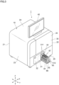
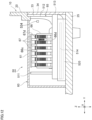
- FIG. 1 is a diagram illustrating a perspective view of an external appearance of a sample measuring apparatus 1 according to the present embodiment.
- FIG. 2 is a diagram illustrating a plan view of an example of an internal configuration of the sample measuring apparatus 1.
- sample measuring apparatus 1 is used for blood coagulation measurement for analyzing the activity of coagulation factor in sample (blood sample).
- sample measuring apparatus 1 includes a substantially rectangular parallelepiped housing (apparatus housing) 10.
- the housing 10 includes the front surface 20, the rear surface 21, the right side surface 22, the left side surface 23, the upper surface 24, and the bottom surface 25.
- “left” and “right” of the sample measuring apparatus 1 is based on directions when the front surface 20 is viewed from the front.
- the front surface 20 is provided with an openable and closable housing 30, and a user can access the inside of the housing 10 by opening the housing 30.
- the front surface 20 is provided with the opening 31 for loading and unloading the reagent rack tray 85 into and from the reagent rack storage 52 described later, and the lid 32 for opening and closing the opening 31.
- the front surface 20 is provided with the opening 33 through which the sample rack tray 65 is inserted into and removed from the sample rack storage 50 described later, and a lid 34 that opens and closes the opening 33.
- the lid 34 is configured to close the opening 33 by being biased toward the housing 10 by a spring and to open the opening 33 by an external force acting against the bias.
- the upper surface 24 is a rectangular flat surface, and the monitor 40 is installed thereon.
- the monitor 40 is a touch panel type display, and displays inputs for operations necessary for sample measurement, display various kinds of information, and display result information of sample measurement.
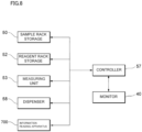
- the sample measuring apparatus 1 includes the sample rack storage 50, the reaction container storage 51, the reagent rack storage 52, the measuring unit 53, the cleaning unit 54, the disposal unit 55, the power supply unit 56, the controller 57, and the dispenser 58.
- the sample measuring apparatus 1 further includes the information reading apparatus 700 that reads identification information of a first object placed in sample rack storage 50 and identification information of a second object placed in the reagent rack storage 52, a first flection unit 710, and a second flection unit 720.
- Sample rack storage 50 is provided closer to the front surface 20 than the center of the housing 10 in the front-rear direction Y and near the center of the housing 10 in the left-right direction X.
- the sample rack storage 50 houses a sample rack that holds a plurality of sample container.
- sample rack storage 50 is covered with the housing member 60.
- the housing member 60 has an upper surface 61, and a plurality of dispensing holes 62 are formed in the upper surface 61.
- a plurality of (six in FIG. 2 ) dispensing holes 62 are arranged side by side on a straight line in the front-rear direction Y.
- the dispensing holes 62 are arranged in two rows adjacent to each other in the left-right direction X.
- a pipette 200 (described later) of the dispenser 58 can enter sample rack storage 50 through the dispensing hole 62 and aspirate sample stored in sample container in sample rack storage 50.
- Sample rack storage 50 stores the sample rack tray 65 on which sample rack is installed. Two sample rack trays 65 are arranged side by side so as to be adjacent to each other in the left-right direction X in sample rack storage 50. That is, the sample rack storage 50 has a space in which two sample rack trays 65 can be arranged in the left-right direction X. As will be described in detail later, sample rack storage 50 includes an electric drive mechanism that moves sample rack trays 65 in the front-rear direction Y, and is configured to be able to independently insert and remove the two sample rack trays 65 based on a user's operation on the monitor 40.
- the first object whose identification information is read by the information reading apparatus 700 is a reagent container held in a reagent rack
- the first setting part in which the first object is installed is the reagent rack tray 85.
- the second objects whose identification information is read by the information reading apparatus 700 are sample container held in sample rack and sample rack, and the second placement portion where the second objects are placed is the reagent rack tray 85.
- the first and second setting part mean places used for installing objects, and are not limited to the sample rack tray 65 and the reagent rack tray 85.
- FIG. 3 is a diagram illustrating a state in which the sample rack tray 65 is pulled out from the housing 10.
- the sample rack tray 65 can be pulled out of the housing 10 through an opening 33 that is opened and closed by a lid 34.
- the lid 34 is pushed by the sample rack tray 65 to open against the urging force.
- the lid 34 is closed by the urging force.
- the lid 34 can open and close the opening 33 in conjunction with the movement of the sample rack tray 65.
- the sample rack tray 65 has an elongated substantially rectangular shape in a plan view, and is placed such that the length direction thereof is along the front-rear direction Y.
- the rear light-shielding wall 511 is provided at a first end portion in the length direction of the tray positioned on the rear side of the housing 10
- the front light-shielding wall 512 is provided at a second end portion in the length direction of the tray positioned on the front side of the housing 10.
- one of the sample rack 66 is placed on one of the sample rack tray 65.
- the sample rack 66 has an elongated substantially rectangular shape in a plan view, and is placed on the sample rack tray 65 such that the length direction thereof is along the front-rear direction Y.
- the sample rack 66 has a structure capable of holding a plurality of the sample container 67 such that the plurality of the sample container 67 are arranged in a line (front-rear direction Y).
- the reaction container storage 51 is provided on the front surface 20 side with respect to the center of the housing 10 in the front-rear direction Y and on the right side with respect to the center of the housing 10 in the left-right direction X.
- the reaction container storage 51 stores the container rack 71 holding reaction containers 70.
- the reagent rack storage 52 is provided on the front surface 20 side with respect to the center of the housing 10 in the front-rear direction Y and on the left side with respect to the center of the housing 10 in the left-right direction X.
- the reagent rack storage 52 is provided on the left side of the sample rack storage 50.
- the reagent rack storage 52 stores a reagent rack holding a plurality of reagent container.
- the reagent rack storage 52 is covered with housing member 80.
- Housing member 80 has an upper surface 81, and a plurality of dispensing holes 82 are formed in the upper surface 81.
- a pipette 200 (to be described later) of the dispenser 58 can enter the reagent rack storage 52 through the dispensing hole 82 and aspirate reagent housed in reagent container in the reagent rack storage 52.
- the reagent rack storage 52 includes a cooling unit 83 for cooling reagent container, and a heat exhaust unit 84 for exhausting heat generated by the cooling unit 83 to the outside of the housing 10.
- the reagent rack tray 85 on which a reagent rack can be placed is installed in the reagent rack storage 52.
- Two reagent rack trays 85 are arranged side by side so as to be adjacent to each other in the left-right direction X in the reagent rack storage 52. That is, the reagent rack storage 52 has a space in which two reagent rack trays 85 can be arranged in the left-right direction X.
- the reagent rack storage 52 may include an electric drive mechanism that moves the reagent rack tray 85 in the front-rear direction Y.
- the user inserts the reagent rack tray 85 into the reagent rack storage 52 and pulls out the reagent rack tray 85 from the reagent rack storage 52, so that the reagent rack tray 85 can be taken in and out.
- the two reagent rack trays 85 can be taken in and out independently of each other.
- FIG. 4 shows a state in which the reagent rack tray 85 is pulled out from the housing 10.
- the reagent rack tray 85 can be pulled out of the housing 10 through the opening 31 that is opened and closed by the lid 32.
- the lid 34 is manually opened and closed.
- the reagent rack tray 85 has an elongated substantially rectangular shape in a plan view, and is placed such that the length direction thereof is along the front-rear direction Y.
- the handle 552 (see FIG. 16 described later) is provided at the end portion of the reagent rack tray 85 in the length direction, and the handle 552 is placed to face the front of the housing 10.
- one of the reagent rack 86 is placed on one of the reagent rack tray 85.
- the reagent rack 86 has an elongated substantially rectangular shape in a plan view, and is placed on the reagent rack tray 85 such that the length direction thereof is along the front-rear direction Y.
- the reagent rack 86 has a structure capable of storing the plurality of the reagent container 87 such that the plurality of the reagent container 87 are arranged in a row (the front-rear direction Y).
- the opening 722 for guiding light of the information reading apparatus 700 to the outside of the device by the function of the second flection unit 720 is formed in the front surface 20 of the housing 10. Further, the front surface 20 is provided with the control lever 726 for operating the movable plate 724 (see FIG. 29 and the like to be described later) constituting the second flection unit 720.
- the opening 722 and the control lever 726 are arranged in a portion of the front surface 20 covered with the lid 32, and are exposed to the outside of the apparatus by opening the lid 32.
- the measuring unit 53 includes the heating unit 90 and the detecting unit 91.
- the heating unit 90 and the detector 91 are provided on the rear surface 21 side with respect to the center of the housing 10 in the front-rear direction Y and on the right side with respect to the center of the housing 10 in the left-right direction X.
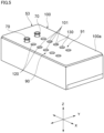
- FIG. 5 is a diagram illustrating an appearance of the measuring unit 53
- FIG. 6 is a diagram illustrating an internal structure of the measuring unit 53.
- the measuring unit 53 includes the housing member 100 including the heating unit 90 and the detecting unit 91.
- the housing member 100 has a substantially rectangular parallelepiped shape.
- the holes 101 are formed in the upper surface 100a of the housing member 100.
- the heating unit 90 includes the first holder 121 inside the housing member 100.
- the first holder 121 has a rectangular parallelepiped shape that is long in the left-right direction X.
- the first holder 121 includes holding holes 120 for retaining the reaction container 70.
- the holding holes 120 are arranged in a row in the left-right direction X.
- the holding hole 120 communicates with the hole 101 placed in the upper surface 100a of the housing member 100.
- the heating unit 90 can heat the reaction container 70 held in the holding hole 120 by the heat source 122.
- the detector 91 includes the second holder 131 inside the housing member 100.
- the second holder 131 has a rectangular parallelepiped shape that is long in the left-right direction X.
- the second holder 131 includes a plurality of holding holes 130 for retaining the reaction container 70.
- the holding holes 130 are arranged in a row in the left-right direction X.
- the second holder 131 is provided on the rear surface 21 side of the first holder 121.
- the holding holes 130 are opened upward and communicates with the hole 101 formed in the upper surface 100a of the housing member 100 to receive and hold the reaction container 70. Since the holding hole 130 is opened upward as described above, light can enter the holding hole 130 from the outside of the housing member 100 and reach the detector 141 described later.
- the detector 91 includes the light source 140 that irradiates the reaction container 70 held by the second holder 131 with light, and the detector 141 that detect the light transmitted through the reaction container 70.
- the detector 91 irradiates sample in the reaction container 70 and a measurement specimen subjected to prepare from reagent with light from the light source 140, and the detector 141 performs detecting on the light transmitted through the measurement specimen, whereby optical information of the measurement specimen can be measured.
- the cleaning unit 54 is provided near the center of the housing 10 in the front-rear direction Y and between the measuring unit 53 and the reaction container storage 51.
- the cleaning unit 54 includes a cleaning tank 160 for cleaning the pipette 200 of the dispenser 58.
- the disposal unit 55 is provided between the measuring unit 53 and the reaction container storage 51.
- the disposal unit 55 includes the disposal outlet 170 for disposing of the reaction container 70.
- the power supply unit 56 is provided near the rear surface 21 of the housing 10 in the front-rear direction Y and on the left side of the center in the left-right direction X.
- the power supply unit 56 supplies power supplied from an external power supply to various devices such as the sample rack storage 50, the reagent rack storage 52, the measuring unit 53, the controller 57, and the dispenser 58.
- the controller 57 is provided near the rear surface 21 of the housing 10 in the front-rear direction Y and on the right side of the center in the left-right direction X. As illustrated in FIG. 8 , the controller 57 can communicate with various devices such as the sample rack storage 50, the reagent rack storage 52, the measuring unit 53, the dispenser 58, and the information reading apparatus 700, and controls operations of the various devices.
- the controller 57 includes a memory and a CPU.
- the CPU executes a program stored in the memory to perform execute, thereby controlling various devices and performing execute for sample measurement.
- the controller 57 can communicate with the monitor 40, and can perform sample measurement based on the information input from the monitor 40 and display the result of the sample measurement on the monitor 40.
- the housing 10 includes therein the vertical wall 180 placed on the rear surface 21 side with respect to the center in the front-rear direction Y.
- the vertical wall 180 includes a plate shape whose plate surface is directed in the front-rear direction Y.
- the vertical wall 180 separates the inside of the housing 10 into a main region R1 and a rear region R2.
- the power supply unit 56 and the controller 57 are attached to a surface of the vertical wall 180 on the rear surface region R2 side.
- the sample rack storage 50, the reaction container storage 51, the reagent rack storage 52, the measuring unit 53, the cleaning unit 54, the disposal unit 55, the dispenser 58, and the information reading apparatus 700 are provided in the main region R1.
- the dispenser 58 has a function of dispensing to the sample container 67, the reaction container 70, and the reagent container 87.
- the dispenser 58 includes the dispensing device 190 and the moving device 191 that moves the dispensing device 190.
- the moving device 191 is configured to transfer the entire dispensing device 190 at any position in the left-right direction X and the front-rear direction Y in the housing 10.
- the container holder 201 that is included in the dispensing device 190 may be moved in the housing 10 by the moving device 191.
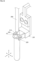
- FIG. 9 is a diagram illustrating perspective view of an example of a configuration of the dispensing device 190.
- the dispensing device 190 includes the pipette 200, the container holder 201, the moving mechanism 202, and the like.
- the pipette 200 is an elongated tube extending in the vertical direction Z, and can hold a predetermined amount of liquid in the tube.
- the pipette 200 is configured to suck a liquid from the tip 210 and perform discharge on the sucked liquid.
- the container holder 201 includes two (a pair of) holding arms 220 that hold the reaction container 70 as shown in FIG. 10 .
- the holding arm 220 is placed below the pipette 200 and can hold the reaction container 70 coaxially in the vertical direction Z of the pipette 200.
- the pipette 200 is narrower than the interval between the two holding arms 220 of the container holder 201, and can be inserted between the two holding arms 220 in the vertical direction Z.
- the moving mechanism 202 relatively moves the pipette 200 and the container holder 201 in the vertical direction Z in a state where the holding arm 220 and the pipette 200 are coaxially maintained.
- the moving mechanism 202 has a mechanical mechanism configured such that when one of the pipette 200 and the container holder 201 is lifted, the other is lowered in conjunction therewith.
- the pipette 200 is lowered, the container holder 201 is lifted in conjunction with the lowering of the pipette 200, and the container holder 201 is lifted to a predetermined position, the moving mechanism 202 is disconnected.
- the pipette 200 has a mechanical mechanism configured to descend in a state where the container holder 201 stops ascending.
- an example of such a mechanical mechanism will be described.
- the moving mechanism 202 includes the first moving unit 250 for moving the pipette 200 in the vertical direction Z, the second moving unit 251 for moving the container holder 201 in the vertical direction Z, the interlocking unit 252 for interlocking the first moving unit 250 and the second moving unit 251, and the drive source 253 for driving the interlocking unit 252.
- the moving mechanism 202 includes a substantially rectangular plate-shaped member 260.
- the plate-shaped member 260 is erected so that the plate surface faces the left-right direction X.
- the first moving unit 250, the second moving unit 251, and the interlocking unit 252 are provided on the first plate surface 260a on the right side (front side in FIG. 9 ) in the left-right direction X of the plate-shaped member 260.
- the drive source 253 is provided on the second plate surface 260b on the left side (back surface side in FIG. 9 ) in the left-right direction X of the plate-shaped member 260.
- the first moving unit 250 includes the pipette holding member 270 that holds the pipette 200, and the first lifting member 271 to which the pipette holding member 270 is fixed and which is lifted and lowered by the interlocking unit 252.
- the pipe 280 for supplying and sucking air into the pipette 200 is connected to an upper portion of the pipette holding member 270.
- the pipe 280 communicates with the pump device.
- the first lifting member 271 has a plate shape.
- the pipette holding member 270 is fixed to a plate surface on the right side in the left-right direction X of the first lifting member 271.
- the first lifting member 271 is movably attached to the first guide rail 272 provided in the vertical direction Z of the plate-shaped member 260.
- the first lifting member 271 is attached to the belt 322 described later.
- the second moving unit 251 includes the second lifting member 300 to which the container holder 201 is fixed and which can be lifted and lowered, the biasing member 301 which moves the second lifting member 300 upward, the stopper 302 which stops the lifting of the second lifting member 300, and the pressing member 303 which is lifted and lowered by the interlocking unit 252 and can press the second lifting member 300 downward.
- the second lifting member 300 includes the main body 310 and the arm 311 connecting the main body 310 and the container holder 201.
- the second lifting member 300 is movably attached to the second guide rail 304 provided in the vertical direction Z of the plate-shaped member 260.
- the biasing member 301 is a spring and is oriented in the vertical direction Z.
- the biasing member 301 has an upper end fixed to a position above the second lifting member 300 of the plate-shaped member 260 and a lower end fixed to an upper portion of the second lifting member 300.
- the biasing member 301 biases the second lifting member 300 upward.
- the stopper 302 is provided at a position above the second lifting member 300 of the plate-shaped member 260.
- the stopper 302 is provided so as to come into contact with an upper portion of the second lifting member 300 and stop the elevation of the second lifting member 300 when the second lifting member 300 is elevated to a predetermined upper limit position, that is, a predetermined position (position in FIGS. 9 and 10 ) where the pipette 200 is inserted into the reaction container 70 held by the holding arm 220 of the container holder 201.
- the pressing member 303 is provided at a position above the second lifting member 300.
- the pressing member 303 is attached to the belt 322 to be described later, and is movable up and down by the belt 322. When the pressing member 303 is lowered, the pressing member 303 can press the second lifting member 300 downward, and can be lifted above the upper limit position of the second lifting member 300.
- the pressing member 303 is lowered by the interlocking unit 252 and the second lifting member 300 is pressed downward against the biasing force of the biasing member 301, and when the container holder 201 is lifted, the pressing member 303 is lifted by the interlocking unit 252 and the second lifting member 300 is lifted by the biasing force of the biasing member 301.
- the stopper 302 stops the upward movement of the second lifting member 300.
- the interlocking unit 252 includes a pair of the pulleys 320 and 321 arranged in the vertical direction Z and the annular belt 322 wound around the pair of the pulleys 320 and 321.
- the pair of pulleys 320 and 321 are placed above and below the plate-shaped member 260.
- the pair of the pulleys 320 and 321 are provided between the first guide rail 272 of the first moving unit 250 and the second guide rail 304 of the second moving unit 251 in the front-rear direction Y.
- the pulley 320 is provided near an upper portion of the plate-shaped member 260, and the pulley 321 is provided near a lower portion of the plate-shaped member 260.
- the belt 322 is wound around a pair of the pulleys 320 and 321, and the belt portions 330 and 331 facing each other in the front-rear direction Y move up and down in opposite directions via the pulleys 320 and 321.
- the first moving unit 250 is driven by the belt portion 330. That is, the first lifting member 271 is attached to the belt portion 330, and the first lifting member 271, the pipette holding member 270, and the pipette 200 are lifted and lowered as the belt portion 330 is lifted and lowered.
- the second moving unit 251 is driven by the belt portion 331. That is, the pressing member 303 is attached to the belt portion 331, and the pressing member 303 moves up and down as the belt portion 331 moves up and down. As the pressing member 303 moves up and down, the second lifting member 300 and the container holder 201 may move up and down.
- the drive source 253 is a single motor and is connected to the pulley 320.
- the drive source 253 is fixed to a second plate surface 260b on the left side in the left-right direction X of the plate-shaped member 260.
- the drive source 253 may switch between forward rotation and reverse rotation, and can rotate the belt 322 clockwise and counterclockwise via the pulley 320.
- the moving mechanism 202 includes the vibrating member 350 that vibrates the reaction container 70 held by the container holder 201.
- the vibrating member 350 includes a vibration element that vibrates by power supply, and is provided on the arm 311 of the second lifting member 300.
- the moving mechanism 202 includes the heating member 360 that heats sample or reagent of the pipette 200.
- the heating member 360 is a heating element that generates heat by power supply, and is provided in the pipette holding member 270.
- FIG. 11 is a diagram illustrating the sample rack tray 65 installed in the sample rack storage 50 and the sample rack 66 holding the sample containers 67 and placed on the sample rack tray 65.
- the sample rack tray 65 includes the elongated base 509 having a rectangular shape in plan view.
- the sample rack tray 65 includes the rear light-shielding wall 511 extending upward from a first end portion of the base 509 in the longitudinal direction, the front light-shielding wall 512 extending upward from a second end portion of the base 509 in the longitudinal direction, and the rack placement unit 510 which is a recessed portion formed in the base 509.
- the sample rack tray 65 is installed in the sample rack storage 50 in a state where the second end portion of the base 509 in the length direction faces forward in the front-rear direction Y.
- the rack placement unit 510 is formed between the rear light-shielding wall 511 and the front light-shielding wall 512 with a size capable of accommodating one of the sample rack 66.
- the rack placement unit 510 stores the sample rack 66 in a state where the length direction of the sample rack 66 is along the length direction of the sample rack tray 65.
- Each of the rear light-shielding wall 511 and the front light-shielding wall 512 has a substantially square plate shape whose plate surface faces the front-rear direction Y, and is formed perpendicular to the base 509.
- the sample rack tray 65 further includes the pressing part 513 formed at a front end of the base 509, and the rail 514 protruding from a side surface of the base 509.
- the pressing part 513 is a portion that presses the lid 34 from the inside of the housing 10 when the sample rack tray 65 is pulled out from the sample rack storage 50, and protrudes further forward than the front light-shielding wall 512.
- the rail 514 is a portion to be inserted into a slider 520 (see FIG. 12 described later) formed on the bottom portion of the sample rack storage 50, and is formed straight along the length direction of the base 509.
- the sample rack 66 includes holders 66b capable of holding a plurality of the sample container 67 in an upright state.
- the number of holders 66b is not particularly limited. In the present embodiment, the six holders 66b are arranged in a line in the longitudinal direction of the sample rack 66.
- the sample rack 66 includes a bottom portion 66a having a rectangular shape in plan view and the partition wall 66c extending upward from the bottom portion 66a.
- the partition wall 66c is formed perpendicularly to the bottom portion 66a, and partitions the holders 66b which are storage spaces of the sample container 67.
- Each of the holders 66b has a size capable of housing one of the sample container 67.
- the sample rack 66 is provided with the sample rack identification information 66d.
- the sample rack identification information 66d is a display including identification information readable by the information reading apparatus 700, and is preferably a one-dimensional code or a two-dimensional code.
- the identification information read from the sample rack identification information 66d is a sample rack identification (ID) and is unique information that can distinguish the sample rack 66 from other racks.
- ID sample rack identification
- a barcode which is a one-dimensional code
- the Sample rack identification information 66d is provided, for example, by attaching a label on which a barcode is printed to the partition wall 66c.
- the sample container 67 is a bottomed cylindrical container containing sample such as blood collected from the subject.
- the sample container 67 is provided with the sample identification information 67d.
- the sample identification information 67d is identification information readable by the information reading apparatus 700, and is a one-dimensional code or a two-dimensional code.
- the identification information read from the sample identification information 67d is a sample ID, which is unique information capable of distinguishing the sample container 67 from other containers.
- a barcode that is a one-dimensional code is provided on a side surface of the sample container 67.
- the sample identification information 67d is provided, for example, by attaching a label on which a barcode is printed to a side surface of the sample container 67.
- FIGS. 12 and 13 are diagrams illustrating a state where the sample rack tray 65 is stored in sample rack storage 50.
- the sample rack storage 50 is configured to store the sample rack tray 65 on which the sample rack 66 is placed.
- the sample rack storage 50 includes two lanes 50a and 50b adjacent to each other in the left-right direction X of the sample rack storage 50, and a plurality of the sample rack 66 can be installed therein.
- Each of the lanes 50a and 50b can accommodate the sample rack tray 65 and is provided with an independent electric drive mechanism.
- the sample rack storage 50 includes the housing member 60 provided to cover the entire the sample rack tray 65.
- the housing member 60 is a light shielding member that surrounds the sample rack tray 65, and includes the opening 60a that allows the sample rack tray 65 to be inserted into and removed from the sample rack storage 50.
- the dispensing hole 62 (see FIG. 2 ) is formed in the upper surface 61 of the housing member 60 to allow sample container 67 to dispense sample.
- the sample rack storage 50 includes the slider 520 provided on the bottom surface 25 of the housing 10.
- the slider 520 includes a groove into which the rail 514 of the sample rack tray 65 is inserted, and extends long in the front-rear direction Y to support the sample rack tray 65 in a state of being movable in the front-rear direction Y.
- the opening 33 through which the sample rack tray 65 can be inserted into and removed from the sample rack storage 50 is formed in the front surface 20 of the housing 10, and the housing member 60 is placed such that the opening 60a overlaps the opening 33.
- the sample rack tray 65 is accommodated in the sample rack storage 50 through the openings 33 and 60a.
- the housing member 60 includes the left side surface 63 and the right side surface 64 that respectively cover left and right sides of the sample rack tray 65 accommodated in the sample rack storage 50.
- the right side surface 64 is in contact with the inner surface of the front surface 20 of the housing 10, and is placed without a gap in between the inner surface of the front surface 20.
- the left side surface 63 is placed with a predetermined gap from the inner surface of the front surface 20. The gap between the left side surface 63 and the front surface 20 allow light emitted from the information reading apparatus 700 to pass therethrough.
- the front light-shielding wall 512 of the sample rack tray 65 is placed so as to close the opening 33, and prevents external light from entering through the opening 33 when the lid 34 is opened.
- the sample rack 66 is placed on the sample rack tray 65 with sample rack identification information 66d facing the left side of the sample measuring apparatus 1.
- the sample rack 66 holds one of the sample containers 67 for each of the holders 66b such that the sample identification information 67d faces the left side of the sample measuring apparatus 1. That is, sample rack identification information 66d and the sample identification information 67d are stored in sample rack storage 50 in a state of facing the same direction.
- the partition wall 66c of the sample rack 66 is formed so as not to cover the side surface of the sample container 67 facing the left side of the sample measuring apparatus 1. Therefore, the sample identification information 67d of the sample container 67 accommodated in holders 66b can be read.
- FIGS. 14 and 15 are diagrams illustrating a state in which the sample rack tray 65 is pulled out from sample rack storage 50.
- the sample rack storage 50 is configured to move the sample rack tray 65 along the front-rear direction Y and to allow the sample rack tray 65 to be taken in and out through the opening 33 of the housing 10.
- the sample rack storage 50 includes the electric drive mechanism 521 that moves the sample rack tray 65.
- the drive mechanism 521 includes the motor 530, the two pulleys 531, and the belt 532 wound around the two pulleys 531.
- the drive mechanism 521 has a structure in which the two pulleys 531 are placed apart from each other in the front-rear direction Y and the belt 532 is arranged along the front-rear direction Y below the slider 520.
- the belt 532 is connected to the sample rack tray 65 via, for example, a predetermined connection fitting.
- the motor 530 is arranged behind sample rack storage 50 and drives the rear pulley 531.
- the belt 532 is interlocked by the driving of the pulley 531 on the rear side, and the sample rack tray 65 connected to the belt 532 moves in the front-rear direction Y along the slider 520.
- the pressing part 513 of the sample rack tray 65 presses the lid 34 from the inside of the housing 10 to open the lid 34 as described above.
- the drive mechanism 521 moves the sample rack tray 65 to a position where the rack placement unit 510 of the sample rack tray 65 is completely pulled out to the outside of the housing 10 and the rear light-shielding wall 511 closes the opening 33. Since the rear light-shielding wall 511 closes the opening 33, external light is prevented from entering the housing 10 through the opening 33.
- the drive mechanism 521 is operated by operating an instruction button of the monitor 40 which is a touch panel.
- the motor 530 is operated based on the operation of the instruction button, the lid 34 is opened by being pushed by the pressing part 513 of the sample rack tray 65, and the sample rack tray 65 is pulled out from sample rack storage 50.
- the instruction button is operated in a state where the sample rack tray 65 is pulled out, the motor 530 is operated to move the sample rack tray 65 into sample rack storage 50.
- the sample rack storage 50 includes the sensor 533 that detects the presence of the sample rack tray 65.
- the sensor 533 is provided behind the sample rack storage 50 inside the housing member 60. In the case where the sample rack tray 65 is stored in the sample rack storage 50 based on the operation of the instruction button, the motor 530 stops when the sample rack tray 65 is detected by the sensor 533 as being subjected to detect.
- the sensor 533 is, for example, a reflective photosensor, and is provided for each of the lanes 50a and 50b.
- the sample rack storage 50 includes a sensor 534 that can detect the presence of the sample rack 66 in the sample rack tray 65.
- a photosensor similar to the sensor 533 may be used as the sensor 534.
- the sensor 534 may be provided for each of the lanes 50a and 50b. The detected information of the sample rack 66 by the sensor 534 may be used as a trigger to start imaging of the information reading apparatus 700.
- FIG. 16 is a diagram illustrating the reagent rack tray 85 stored in the reagent rack storage 52.
- the groove 560 into which a lower portion of the reagent rack tray 85 is fitted is formed in a bottom portion of the reagent rack storage 52.
- the groove 560 extends in the front-rear direction Y and serves as a guide when the reagent rack tray 85 is moved in the front-rear direction Y.
- the reagent rack tray 85 includes the rack placement unit 550, the wall 551 provided in front of the rack placement unit 550, and the handle 552 extending forward from an upper end portion of the wall 551.
- the reagent rack storage 52 does not have an electric drive mechanism, and the reagent rack tray 85 is manually moved in the front-rear direction Y by the user holding the handle 552.
- the wall 551 functions as a lid that closes the opening of the cooling unit 83 when the sample rack tray 65 is housed in the reagent rack storage 52.
- the reagent rack 86 includes the holders 86b capable of holding a plurality of reagent container 87 in an upright state.
- the number of the holders 86b is not particularly limited. In the present embodiment, six of the holders 86b are arranged in a line in the longitudinal direction of the reagent rack 86.
- the reagent rack 86 includes a bottom portion 86a having a rectangular shape in plan view and a wall 86c extending upward from the bottom portion 86a.
- the wall 86c is formed to be slightly inclined from the vertical direction with respect to the bottom portion 86a, and partitions the holders 86b which are storage spaces of the reagent container 87.
- the reagent rack 86 includes the position information 86d.
- the position information 86d is position information of each of the holders 86b, and is provided on the wall 86c adjacent to one of the holders 86b.
- the position information 86d may be a two-dimensional code, but in the example illustrated in FIG. 16 , the position information 86d is configured by a barcode which is a one-dimensional code.
- the position information 86d may be provided, for example, by attaching a label on which a barcode is printed to the wall 86c.
- the reagent rack 86 does not have a rack ID.
- the reagent rack 86 further includes absence information 86e.
- An example of the absence information 86e is a bar code, and may be provided by attaching a label on which the bar code is printed to reagent rack 86.
- the absence information 86e is provided on a wall portion forming an inner surface of the holders 86b at a position readable when the reagent container 87 is not accommodated in the holders 86b.
- the position information 86d and the absence information 86e are provided to face the same direction.
- the reagent rack 86 is placed on the reagent rack tray 85 such that the position information 86d and the absence information 86e face the apparatus left side.
- the reagent container 87 is a bottomed cylindrical container containing a reagent for preparing measurement of specimen to be measured.
- the reagent container 87 is provided with the reagent identification information 87d.
- the reagent identification information 87d is identification information readable by the information reading apparatus 700, and is a one-dimensional code or a two-dimensional code.
- the identification information read from the reagent identification information 87d is a reagent ID, which is unique information that can distinguish the reagent container 87 from other containers.
- reagent containers 87 are held by three holders 86b of the reagent rack 86 one by one.
- Barcodes which are one-dimensional codes, are provided on the side surfaces of the two reagent containers 87, and a two-dimensional code is provided on the side surface of one of the reagent container 87.
- An example of the two-dimensional code is a QR code (registered trademark).
- the reagent identification information 87d can be provided, for example, by attaching a label on which a one-dimensional code or a two-dimensional code is printed to a side surface of the reagent container 87.
- FIG. 17 is a flowchart showing a process of sample measurement.
- reaction container transfer step S1 the sample dispensing step S2, the reagent dispensing step S3, the measurement step S4, and the reaction container collection and disposal step S5 may be mainly performed in this order. These steps may be executed by the controller 57.
- a plurality of empty reaction container 70 are stored in the reaction container storage 51 as shown in FIG. 2 .
- the sample rack 66 including the plurality of the sample container 67 accommodating sample is held by the sample rack tray 65 and accommodated in the sample rack storage 50.
- the reagent rack 86 including the reagent container 87 accommodating reagent is held by the reagent rack tray 85 and accommodated in the reagent rack storage 52.
- the transfer step S1 of the reaction container 70 is performed.
- the container holder 201 of the dispensing device 190 moves from an initial position onto the container rack 71 of reaction container storage 51, and then is descended to hold an empty reaction container 70 of the container rack 71.
- the container holder 201 moves onto the heating unit 90 and then is descended, and the reaction container 70 is held in the holding hole 120 of the heating unit 90. Then, the container holder 201 is lifted.
- the sample dispensing step S2 is performed.
- the pipette 200 of the dispensing device 190 is moved above the sample rack storage 50 and lowered.
- the pipette 200 is inserted into the sample container 67 of the sample rack 66 held in the sample rack tray 65 through the dispensing hole 62 in the upper surface 61 of the housing member 60 to aspirate sample.
- the pipette 200 is lifted above the sample rack storage 50 and moves above the heating unit 90.
- the pipette 200 is descended toward the reaction container 70 of the heating unit 90 and injects sample into the reaction container 70.
- the pipette 200 is lifted above the heating unit 90 and moves above the cleaning unit 54.
- the pipette 200 is descended toward the cleaning tank 160 of the cleaning unit 54, is inserted into the cleaning tank 160, and is cleaned.
- the pipette 200 is lifted above the cleaning unit 54.
- the reagent dispensing step S3 is performed.
- the pipette 200 moves onto the reagent rack storage 52 and is descended.
- the pipette 200 is inserted into the reagent container 87 of the reagent rack 86 held by the reagent rack tray 85 through the dispensing hole 82 in the upper surface 81 of housing member 80, and aspirate reagent.
- the pipette 200 then is lifted above the reagent rack storage 52. Next, reagent of the pipette 200 is heated by the heating member 360. The pipette 200 moves onto the heating unit 90 while reagent of the pipette 200 is heated.
- the container holder 201 of the dispensing device 190 is descended toward the reaction container 70 of the heating unit 90 and holds the reaction container 70 of the heating unit 90.
- the container holder 201 is lifted above the heating unit 90, and the pipette 200 is descended and is inserted into the reaction container 70.
- the pipette 200 then injects reagent into the reaction container 70 of the container holder 201.
- the reaction container 70 of the container holder 201 is vibrated by the vibrating member 350, sample containing reagent is agitated, and the measured reagent is prepared.
- the container holder 201 shown in FIG. 2 moves onto the detector 91 and then is descended.
- the container holder 201 is descended toward the holding hole 130 of the detector 91 to hold the reaction container 70 in the holding hole 130.
- the container holder 201 is lifted on the detector 91.
- the measurement step S4 is performed.
- Sample measurement performed in the measurement step S4 is affected by external light.
- the detector 91 blood coagulation measurement for analyzing the activity of coagulation factor of sample accommodated in the reaction container 70 is performed.
- the measurement is performed by irradiating a measurement specimen in the reaction container 70 with light from the light source 140, performing detect on the light transmitted through the measurement specimen by the detector 141, and measuring optical information of the measurement specimen.
- the optical information is time-series data of the light subjected to detect by the detector 141. That is, the optical information is time-series data that is continuously subjected to detect for a predetermined time, and the time for which the time-series data is subjected to detect is about 30 seconds to 5 minutes.
- the time series data may be a plurality of pieces of time series data obtained by performing detect on light of wavelengths that has passed through the measurement specimen.
- the time series data may be for calculating coagulation time of sample, the concentration of a component contained in sample, or the activity, and coagulation time of sample may be calculated from the time series data using the percent detect method.
- the concentration or activity of a component contained in sample may be calculated from the time-series data using a synthetic substrate measurement method, and the concentration or activity of a component contained in sample may be calculated from the time-series data using an immunoturbidimetric measurement method.
- reaction container collection and disposal step S5 is performed. First, the container holder 201 of the dispensing device 190 shown in FIG. 2 moves above the detector 91 and then descends. Next, the container holder 201 holds the reaction container 70 of the detector 91.
- the container holder 201 is lifted above the detector 91 and moves onto the disposal unit 55.
- the container holder 201 is descended toward the disposal outlet 170 of the disposal unit 55 and disposes of the reaction container 70 to the disposal outlet 170.
- the container holder 201 is lifted above the disposal unit 55 and then returned to its initial position.
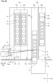
- FIG. 18 is a diagram illustrating the information reading apparatus 700 and the first flection unit 710
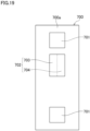
- FIG. 19 is a diagram illustrating a front surface 700a of the information reading apparatus 700.
- FIG. 18 shows a state in which the sample rack tray 65 and the reagent rack tray 85 are accommodated in the sample rack storage 50 and the reagent rack storage 52, respectively.
- sample container 67 existing in front of the sample rack storage 50 is indicated by a virtual line.
- the light source 701 of the information reading apparatus 700 emits light
- the first flection unit 710 guides a part of reflected light from sample container 67 to the light receiver 702 of the information reading apparatus 700.
- the remaining part of reflected light directly enters the light receiver 702 without passing through the first flection unit 710.
- a part of the emission light emitted from the light source 701 is irradiated through the first flection unit 710, and the remaining part of the emission light is directly irradiated without passing through the first flection unit 710.
- the identification information of the sample rack 66 and sample container 67, the position information 86d of the reagent rack 86, and the identification information of the reagent container 87 are read in front of the sample rack storage 50 and the reagent rack storage 52.
- the position between the front surface 20 of the housing 10 and the position where the rack tray is completely housed in each rack installation part, that is, the introduction path to the housing position of the sample rack 66 and the reagent rack 86 is the reading position of the identification information.
- the information reading apparatus 700, the first flection unit 710, the reagent rack storage 52, and the sample rack storage 50 are arranged in order from the left side of the apparatus.
- the sample rack storage 50 is provided at a position geometrically farther from the information reading apparatus 700 than the reagent rack storage 52.
- the information reading apparatus 700 includes the light source 701 and the light receiver 702, and is a device that irradiates an object such as sample container 67 or the reagent container 87 with light, receives reflected light from the object, and reads identification information thereof.
- the light source 701 and the light receiver 702 are provided on a front surface 700a of the information reading apparatus 700.
- the light sources 701 are arranged so as to sandwich the light receiver 702 from above and below.
- the information reading apparatus 700 is placed close to the front surface 20 of the housing 10 in a state where the front surface 700a faces the right direction of the sample measuring apparatus 1.
- a one-dimensional code reader generally called a barcode reader, or a two-dimensional code reader called a QR code reader can be used.
- a two-dimensional code reader is preferably used for the information reading apparatus 700.
- the light source 701 of the information reading apparatus 700 includes, for example, a light emitting diode (LED).
- the light receiver 702 includes, for example, a light receiving element such as a CCD image sensor or a CMOS image sensor, and a single focus lens having a fixed focal range that forms an image of the received reflected light on the image sensor.
- the light receiving element is also referred to as an imaging element.
- the light receiving element When light is incident on pixels arranged in a grid pattern, the light receiving element generates electric charges corresponding to the intensity of the light, and detect the light intensity of each pixel by extracting the magnitude of the electric charges as an electric signal. For example, the light receiving element converts detected light intensity into grayscale data of 256 gradations, and generates an image based on the data. It can be said that the information reading apparatus 700 is constituted by a digital camera including a decoding function described later. The processor of the digital camera has a decoding function.
- the information reading apparatus 700 has a predetermined focus (hereinafter, referred to as "focus” in some cases) and is used in a state where the focus is fixed. Since the information reading apparatus 700 does not have an autofocus function and does not adjust the focus range when the imaging sample container 67, the reagent container 87, and the like, it is possible to quickly read the identification information. In addition, an inexpensive reader having no autofocus function can be used.
- the information reading apparatus 700 is focused on an area in front of the sample rack storage 50 that is geometrically far from the information reading apparatus 700. That is, the focus of the information reading apparatus 700 is fixed to the sample rack tray 65 passing through the area in front of the sample rack storage 50, and the area in front of the reagent rack storage 52 is not focused on a linear distance.
- the sample measuring apparatus 1 is not provided with a mechanism or a control circuit for automatically adjusting the focus by moving the information reading apparatus 700 in the left-right direction X.
- the sample measuring apparatus 1 it is possible to accurately read the identification information in both the area in front of the sample rack storage 50 and the area in front of the reagent rack storage 52 using one information reading apparatus 700 which does not have an autofocus function and has a fixed position. That is, the first reflected light from the reagent container 87 passing through the area in front of the reagent rack storage 52 is corrected by the first flection unit 710. Accordingly, the optical distance of the first reflected light acquired via the first flection unit 710 and the optical distance of the second reflected light acquired from the sample container 67 passing through the area in front of the sample rack storage 50 without passing through the flection unit 710 can be made substantially the same.
- the information reading apparatus 700 can be focused on the reagent container 87 and the sample container 67 having different geometric distances.
- the information reading apparatus 700 captures images of the sample rack 66 and the sample container 67 passing through the area in front of the sample rack storage 50.
- sample rack identification information 66d and the sample identification information 67d are extracted from the obtained image, and the identification information (the rack ID and sample ID) is read.
- a series of processes of reading the identification information from the obtained image is generally called decoding.
- the information reading apparatus 700 performs imaging and decoding, and transmits the read rack ID and sample ID to the controller 57.
- a specific decoding method is not particularly limited.
- the controller 57 stores the rack ID of the sample rack 66 stored in sample rack storage 50 and sample ID of the sample container 67 in the memory, and performs sample execute measurement using the information.
- the information reading apparatus 700 may start imaging the area in front of the sample rack storage 50.
- the instruction button When the instruction button is operated in a state where the sample rack tray 65 is pulled out, the sample rack tray 65 moves toward the inside of the sample rack storage 50.
- the sample rack 66 placed on the sample rack tray 65 passes through the area in front of the sample rack storage 50. Therefore, the sample rack 66 and the sample container 67 can be imaged by starting imaging based on the operation of the instruction button.
- the information reading apparatus 700 receives a control signal for starting imaging from the controller 57.
- the controller 57 is configured to transmit a control signal for starting imaging to the information reading apparatus 700 upon receiving an operation signal of the instruction button.
- the information reading apparatus 700 may start imaging when the sensor 534 detect the sample rack 66.
- the information reading apparatus 700 receives a control signal for starting imaging from the controller 57, for example, when the sample rack 66 is detected by the sensor 534.
- the controller 57 is configured to transmit a control signal for starting imaging to the information reading apparatus 700 upon receiving detect signal of the sensor 534.
- the controller 57 preferably controls the drive mechanism 521 such that the sample rack tray 65 moves to the rear of the apparatus while temporarily stopping at the position of each of the sample container 67 when each of the sample container 67 passes through the area in front of the sample rack storage 50.
- the time during which each of the sample container 67 stops is, for example, 0.1 seconds to 5 seconds. In this case, the accuracy of reading the sample identification information 67d is improved as compared with the case where the sample rack tray 65 is continuously moved. Since the sample rack identification information 66d is provided on the partition wall 66c adjacent to the holder 66b, the sample rack identification information 66d may be read at the same time when the sample identification information 67d of the adjacent sample container 67 is read.
- the information reading apparatus 700 ends the imaging at a timing when the identification information of the sample rack 66 and all the sample container 67 placed on the sample rack tray 65 is read. For example, the information reading apparatus 700 ends the imaging when the sensor 533 provided at the rear of the sample rack storage 50 detects the sample rack tray 65. In this case, the controller 57 is configured to transmit a control signal for ending imaging to the information reading apparatus 700 upon receiving detect signal of the sensor 533.
- the information reading apparatus 700 captures an image of an area in front of the reagent rack storage 52 and reads the position information 86d of the reagent rack 86 and the identification information of the reagent container 87 passing through the area.
- the reagent rack tray 85 on which the reagent rack 86 is placed is manually moved in the front-rear direction Y.
- the information reading apparatus 700 starts imaging, for example, when the reagent sensor 570 installed in front of the reagent rack storage 52 detects that detect the reagent rack tray 85 is moved.
- the controller 57 is configured to transmit a control signal for starting imaging to the information reading apparatus 700 upon receiving detect signal of the sensor 570.
- the first flection unit 710 is placed between the information reading apparatus 700 and the reagent rack storage 52, and bends reflected light from the sample container 67, the reagent container 87, and the like. Note that a part of reflected light directly enters the light receiver 702 without passing through the first flection unit 710. That is, the first flection unit 710 is configured not to shield a part of reflected light (hereinafter, may be referred to as "direct light") directly incident on the light receiver 702.
- the first flection unit 710 bends the optical axis of a part of the light emitted from the light source 701 of the information reading apparatus 700 and guides the light to the area in front of the sample rack storage 50 and the area in front of the reagent rack storage 52.
- optical axis of the first reflected light incident on the information reading apparatus 700 through the first flection unit 710 is referred to as an "optical axis a1"
- optical axis of the second reflected light incident on the information reading apparatus 700 without passing through the first flection unit 710 is referred to as an "optical axis a2”.
- the information reading apparatus 700 is focused on the area in front of the sample rack storage 50, but the distance of the optical path between the information reading apparatus 700 and the area in front of the reagent rack storage 52 close to the information reading apparatus 700 can be increased by the function of the first flection unit 710. As a result, it is possible to acquire a focused and clear image of the reagent rack 86 and the reagent container 87 that pass through the area in front of the reagent rack storage 52.
- the light receiver 702 when sample ID is read from the sample identification information 67d of the sample container 67, an image generated from direct light is used for the light receiver 702.
- the light receiver 702 also includes reflected light incident from the sample container 67 via the first flection unit 710, but an image generated from reflected light is not used for reading sample ID.
- the reagent ID is read from the reagent identification information 87d of the reagent container 87, an image generated from reflected light incident on the light receiver 702 through the first flection unit 710 is used.
- an image generated by the light receiver 702 from direct light is not used.
- the light receiver 702 includes the first light receiving region 703 and the second light receiving region 704.
- the first light receiving region 703 is a region on which reflected light is incident via the first flection unit 710
- the second light receiving region 704 is a region on which direct light is incident.
- the image generated by the first light receiving region 703 is used for reading reagent ID
- the image generated by the second light receiving region 704 is used for reading sample ID.
- the first light receiving region 703 and the second light receiving region 704 can be set on the left and right sides of the light receiver 702 when the front surface 700a is viewed from the front by a mirror arrangement of the first flection unit 710 described later.
- the first flection unit 710 is preferably formed of at least two mirrors, and includes the first mirror 711 placed to face the front surface 700a of the information reading apparatus 700 and the second mirror 712 placed not to face the front surface 700a.
- the second mirror 712 is placed behind the information reading apparatus 700.
- a part of reflected light from the sample container 67, the reagent container 87, and the like is reflected by the second mirror 712 and the first mirror 711 in this order, and enters the light receiver 702.
- the information reading apparatus 700, the first mirror 711, the second mirror 712, and the sample container 67 are arranged on the same horizontal plane.
- the first mirror 711 is a reflection member that guides reflected light from the sample container 67, the reagent container 87, and the like reflected by the second mirror 712 to the light receiver 702. Therefore, the first mirror 711 is placed in a state of facing the second mirror 712 and the front surface 700a of the information reading apparatus 700. Since both the second mirror 712 and the front surface 700a face the apparatus right side and are placed adjacent to each other in the front-rear direction Y, the second mirror 712 is placed in a state of facing the apparatus left rear side.
- the reflection surface of the first mirror 711 faces, for example, the left rear side of the apparatus at an angle of 45° ⁇ 15° with respect to the front surface 700a.
- the first mirror 711 is interposed between the information reading apparatus 700 and the reagent rack storage 52, and is placed so as to shield a part of the front surface 700a when the front surface 700a of the information reading apparatus 700 is viewed from the device right side.
- the first mirror 711 is placed close to the front surface 20 of the housing 10, and is placed to face a range of about half of the front surface 700a on the front surface 20 side. In other words, when the front surface 700a is viewed from the apparatus right side, a range of about half of the front surface 700a on the apparatus rear side is not covered with the first mirror 711.
- the first mirror 711 With the above arrangement of the first mirror 711, a part of reflected light from the sample container 67, the reagent container 87, and the like directly enters the light receiver 702. Specifically, light is directly incident on a region not facing the first mirror 711, and the region of the light receiver 702 becomes the second light receiving region 704. A region of the light receiver 702 which faces the first mirror 711 and in which direct light is blocked is a first light receiving region 703.
- the range of the front surface 700a facing the first mirror 711 can be adjusted by the size, angle, and the like of the first mirror 711 and is not particularly limited, but is, for example, 30% to 70% of the area of the front surface 700a.
- the second mirror 712 is a reflection member that reflects reflected light from the sample container 67, the reagent container 87, and the like toward the first mirror 711. For this reason, the second mirror 712 is placed in a state facing the apparatus right side and the direction of the first mirror 711.
- the second mirror 712 is larger than the first mirror 711. Since the second mirror 712 is not placed to face the front surface 700a of the information reading apparatus 700, the second mirror 712 is preferably larger than the first mirror 711 from the viewpoint of collecting a large amount of reflected light.
- the angle of the reflecting surface of the second mirror 712 with respect to the reflecting surface of the first mirror 711 is not particularly limited, and the reflecting surfaces may be substantially parallel to each other.
- the configurations of the information reading apparatus 700 and the first flection unit 710 are further described in detail by exemplifying a case of reading the sample identification information 67d of the sample container 67 with reference to FIGS. 20 to 22 .
- FIGS. 20 and 21 are diagrams illustrating a state in which the sample identification information 67d of the sample container 67 held in the sample rack 66 is read.
- the sample rack storage 50 has two lanes 50a and 50b arranged in the left-right direction X of the apparatus, and can store one of the sample racks 66 in each lane, but the reading of the identification information of the sample rack 66 and the sample container 67 is performed for each lane.
- the sample rack 66 and the sample container 67 pass in front of the sample rack storage 50 and move to the rear of the sample rack storage 50 in a state of being placed on the sample rack tray 65, and the identification information is read when passing in front of the sample rack storage 50.
- the information reading apparatus 700 captures an image of the sample container 67 when the sample rack tray 65 passes through the area in front of the sample rack storage 50.
- the light receiver 702 of the information reading apparatus 700 generates an image from reflected light of the sample container 67.
- the information reading apparatus 700 analyzes the image, extracts the sample identification information 67d which is a barcode, and reads sample ID.
- the optical axis ⁇ 1 of the bent reflected light (hereinafter, may be referred to as "refracted light") is incident only on the first light receiving region 703 of the light receiver 702 by the mirror arrangement.
- the optical axis ⁇ 2 of reflected light directly incident from the sample container 67 without passing through the first flection unit 710 is incident only on the second light receiving region 704 of the light receiver 702. Therefore, it is possible to separate an image generated from the direct light and an image generated from the refracted light. Since the image generated from the direct light is in focus and clear, sample ID can be accurately read by using the image generated in the second light receiving region 704.
- the two lanes 50a and 50b of the sample rack storage 50 are arranged adjacent to each other in the left-right direction X, and are both arranged within a range in which an image generated from direct light is in focus, that is, within a depth of field.
- the information reading apparatus 700 has such a depth of field that the image of the sample container 67 passing through the lane 50a and the image of the sample container 67 passing through the lane 50b are in focus.
- An example of the depth of field of the information reading apparatus 700 is 70 mm to 150 mm.
- KL1 and KL2 are second optical distances through which the second reflected light, which is direct light, passes between the identification information reader 700 and the sample rack tray 65 of each lane, and these optical distances are fixed distances that do not vary.
- the information reading apparatus 700 When reading the sample identification information 67d of the sample container 67, the information reading apparatus 700 preferably performs execute decoding processing using only the image generated by the second light receiving region 704 of the light receiver 702 as described above. Specifically, prior to the decoding process, the image generated by the entire region of the light receiver 702 is trimmed to delete the image generated by the first light receiving region 703. Then, the decoding processing is performed only on the image generated by the second light receiving region 704, that is, the image obtained from the direct light by execute. In this case, the decoding process can be performed using only the focused and clear image of the sample identification information 67d. As a result, the reading accuracy of the identification information is improved, and the processing speed is also increased.
- FIGS. 22A and 22B are diagrams illustrating an image of the area in front of the sample rack storage 50 captured by the information reading apparatus 700.
- FIG. 22A is a diagram illustrating an image 800 before the trimming process
- FIG. 22B is a diagram illustrating an image after the trimming process.
- the image 800 includes the image 801 of the refracted light generated by the first light receiving region 703 of the light receiver 702 and an image 802 of the direct light generated by the second light receiving region 704.
- An image 801 is an image reflected on the first mirror 711 of the first flection unit 710, and an end of the first mirror 711 is a boundary between the images 801 and 802. Therefore, the boundary between the out-of-focus image 801 of the refracted light and the in-focus image 802 of the direct light is clear, and it is easy to leave only the image 802 by trimming.
- the trimming process by the information reading apparatus 700 is executed based on, for example, a control signal of the controller 57.
- the controller 57 reads the sample identification information 67d
- the controller 57 outputs a control signal for deleting the image 801 generated by the first light receiving region 703 and a control signal for executing a decoding process using only the image 802 generated by the second light receiving region 704, together with a control signal for starting imaging.
- the information reading apparatus 700 may further trim the image 802 to delete the image around the sample identification information 67d and then execute the decoding process.
- the controller 57 grasps the position of each of the sample container 67 held in line in the sample rack 66, that is, the position of holder 66b of the sample rack 66 in which each sample container 67 is accommodated.
- Each of the lanes 50a and 50b of the sample rack storage 50 is provided with an independent electric drive mechanism 521. Therefore, the controller 57 is capable of acquiring, for example, information for specifying holder 66b existing in the area in front of the sample rack storage 50 from the drive mechanism 521.
- the controller 57 stores sample ID of the sample container 67 read by the information reading apparatus 700 in association with the position information of holder 66b. When the sample container 67 is not accommodated in holder 66b, the sample identification information 67d is not read. The fact that the sample container 67 is not accommodated in holder 66b is stored.
- the configurations of the information reading apparatus 700 and the first flection unit 710 will be further described in detail by exemplifying a case of reading the reagent identification information 87d of the reagent container 87 with reference to FIGS. 23 to 25 as appropriate.
- FIGS. 23 and 24 are diagrams illustrating a state in which the reagent identification information 87d of the reagent container 87 held by the reagent rack 86 is read.
- the reagent rack storage 52 includes two lanes 52a and 52b arranged in the left-right direction X of the apparatus. Therefore, one of the reagent rack 86 can be stored in each lane. The position information 86d of the reagent rack 86 and the identification information of the reagent container 87 are read for each lane.
- the reagent rack 86 and the reagent container 87 which are placed on the reagent rack tray 85, pass through the front of the reagent rack storage 52 and move into the reagent rack storage 52, and the identification information is read when the reagent rack 86 and the reagent container 87 pass through the front of the reagent rack storage 52.
- the information reading apparatus 700 captures an image of the reagent container 87 when the reagent rack tray 85 passes through the area in front of the reagent rack storage 52.
- the light receiver 702 of the information reading apparatus 700 generates an image from reflected light of the reagent container 87.
- the information reading apparatus 700 analyzes the image, extracts the reagent identification information 87d which is a barcode or a QR code (registered trademark), and reads reagent ID.
- the reagent ID can be read using the image of the refracted light generated in the first light receiving region 703.
- the distance SL1 of the path of the refracted light incident on the first light receiving region 703 via the first flection unit 710 from the reagent container 87 passing through the left lane 52a illustrated in FIG. 23 is a length obtained by adding SLa, SLb, and SLc.
- SLa is the distance of the optical path from the reagent container 87 to the second mirror 712
- SLb is the distance of the optical path from the second mirror 712 to the first mirror 711
- SLc is the distance of the optical path from the first mirror 711 to the light receiver 702.
- SL1 is a first optical distance through which the first reflected light that is the refracted light passes between the identification information reader 700 and the reagent rack tray 85 of each lane, and this optical distance is a fixed distance that does not change.
- the first optical distance SL1 of the refracted light from the reagent container 87 is a length approximate to the second optical distances KL1 and KL2 (see FIGS. 20 and 21 ) of the direct light from the sample container 67, and is a length within the depth of field of the information reading apparatus 700. That is, the mirror arrangement of the first flection unit 710 is determined so that SL1 falls within the depth of field. In other words, the first optical distance SL1 and the second optical distances KL1 and KL2 are substantially the same. Therefore, the image of the reagent container 87 generated from the refracted light is in focus and clear, and the reagent ID can be accurately read by using the image generated in the first light receiving region 703.
- the distance SL2 of a path of the refracted light incident on the first light receiving region 703 from the reagent container 87 passing through the lane 52b on the right side illustrated in FIG. 24 via the first flection unit 710 is a length obtained by adding SLa, SLb, and SLc, similarly to SL1.
- This is a fixed first optical distance that does not vary and through which the first reflected light that is refracted light passes between the identification information reader 700 and the reagent rack tray 85 of each lane.
- the distance SLa of the optical path from the reagent container 87 to the second mirror 712 is longer than SLa in the case of the lane 52a.
- SL2 is also set to a length within the depth of field of the information reading apparatus 700.
- the two lanes 52a and 52b of the reagent rack storage 52 are placed adjacent to each other in the left-right direction X, and are both positioned in a range in which an image generated from the refracted light (optical axis ⁇ 1) is in focus.
- the information reading apparatus 700 When reading the reagent identification information 87d of the reagent container 87, the information reading apparatus 700 preferably performs execute decoding processing using only the image generated by the first light receiving region 703 of the light receiver 702 as described above. Specifically, prior to the decoding process, the image generated by the entire region of the light receiver 702 is trimmed to delete the image generated by the second light receiving region 704. Then, the decoding processing is performed only on the image generated by the first light receiving region 703, that is, the image obtained from the refracted light by execute. In this case, the decoding process can be performed using only the focused and clear image of the reagent identification information 87d. As a result, the reading accuracy of the identification information is improved, and the processing speed is also increased.
- FIGS. 25A and 25B is a diagram illustrating an image of an area in front of the reagent rack storage 52 captured by the information reading apparatus 700.
- FIG. 25A is a diagram illustrating an image 900 before the trimming process
- FIG. 25B is a diagram illustrating an image after the trimming process.
- the image 900 includes an image 901 of the refracted light generated by the first light receiving region 703 of the light receiver 702 and an image 902 of the direct light generated by the second light receiving region 704.
- An image 901 is an image reflected on the first mirror 711 of the first flection unit 710, and an end of the first mirror 711 is a boundary between the images 901 and 902. Therefore, the boundary between the focused image 901 of the refracted light and the unfocused image 902 of the direct light is clear, and it is easy to leave only the image 901 by trimming.
- the trimming process by the information reading apparatus 700 is executed based on, for example, a control signal of the controller 57.
- the controller 57 When reading the reagent identification information 87d, the controller 57 outputs a control signal for deleting the image 902 generated by the second light receiving region 704 and a control signal for executing a decoding process using only the image 901 generated by the first light receiving region 703 together with a control signal for starting imaging.
- the information reading apparatus 700 may further trim the image 901 to delete the image around the reagent identification information 87d and then execute the decoding process.
- the controller 57 grasps the position of each of the reagent container 87 held in line in reagent rack 86, that is, the position of the holders 86b of the reagent rack 86 in which each of the reagent container 87 is housed.
- the position information 86d including the position information of each of the holders 86b is provided adjacent to each of the holders 86b. Therefore, when the position information 86d is read together with the reagent identification information 87d by the information reading apparatus 700, the controller 57 can specify the position of each of the reagent container 87 and store the reagent ID in association with the position information of the holders 86b.
- the absence information 86e is read and information indicating that the reagent container 87 is not accommodated in one of the holders 86b is stored.
- FIG. 26 shows a modification of the above embodiment in which an additional mirror 715 is arranged between the information reading apparatus 700 and the sample container 67.
- the mirror 715 is a reflection member that bends the first reflected light (optical axis ⁇ 1) bent by the first mirror 711 and the second mirror 712 and the second reflected light (optical axis ⁇ 2) directly incident from the sample container 67 and guides them in the direction of the information reading apparatus 700. Further, the mirror 715 bends the light emitted from the information reading apparatus 700 to enable the sample container 67 to be irradiated with the light.
- the mirror 715 does not increase the difference between the distances of the optical paths of the optical axis ⁇ 1 of the first reflected light and the optical axis ⁇ 2 of the second reflected light. This leads reflected light to the information reading apparatus 700 which is not arranged to face the sample container 67.
- the information reading apparatus 700 reads the sample identification information 67d from the second reflected light (optical axis ⁇ 2) whose optical axis is bent a smaller number of times than the first reflected light.
- the reagent identification information 87d of the reagent container 87 is read from the first reflected light (optical axis ⁇ 1).
- the mirror 715 is placed on the same horizontal plane as the first mirror 711, the second mirror 712, and the sample identification information 67d, but the information reading apparatus 700 is placed above the horizontal plane. Therefore, the reflecting surface of the mirror 715 is inclined vertically upward.
- the information reading apparatus 700 may be placed below the horizontal plane, and the mirror 715 may be inclined vertically downward.
- FIG. 27 is a flowchart showing a process of reading the sample identification information 67d, and shows operations of the controller 57 and the information reading apparatus 700.
- the sample rack tray 65 is pulled out from sample rack storage 50
- the sample rack 66 holding the plurality of the sample container 67 is placed on the sample rack tray 65, and the sample rack tray 65 is introduced into sample rack storage 50.
- the sample identification information 67d is read.
- step S10 the controller 57 receives an operation signal of the instruction button of the monitor 40 (Yes in step S10). Upon receiving the operation signal, the controller 57 starts a series of information reading steps together with the information reading apparatus 700. When the operation signal of the instruction button is not received (No in step S10), the process does not proceed to the next step S11.
- the controller 57 Upon receiving the operation signal of the instruction button of the monitor 40, the controller 57 transmits a control signal to the drive mechanism 521 of the sample rack storage 50. Then, the sample rack tray 65 moves toward the inside of the sample rack storage 50.
- the drive mechanism 521 intermittently drives the motor 530 under the control of the controller 57 to move the sample rack tray 65 while temporarily stopping each of the sample container 67 in an area in front of the sample rack storage 50.
- step S11 the controller 57 transmits an imaging start control signal (imaging start command) to the information reading apparatus 700.
- the information reading apparatus 700 Upon receiving a control signal to start imaging from the controller 57 (Yes in step S100), the information reading apparatus 700 emits light from the light source 701, starts imaging the area in front of the sample rack storage 50 through which the sample container 67 passes, and acquires an image 800 including the sample container 67 (step S101).
- the control signal for starting imaging is not received (No in step S100)
- the process does not proceed to the next step S101.
- step S12 the controller 57 transmits a control signal for designating a trimming area of the image to the information reading apparatus 700.
- the image 802 of the direct light generated by the second light receiving region 704 of the light receiver 702 is used. Therefore, the controller 57 designates, for example, the image 802 as a target of the decoding process. Since the image of the sample identification information 67d in the image 802 is a sharp image in focus, the sample identification information 67d can be accurately read, and the processing speed is increased by narrowing the processing range.
- the information reading apparatus 700 performs a trimming process of deleting the image 801 generated by the first light receiving region 703 from the entire image 800 and leaving the image 802 (step S102).
- a decoding process is performed using the image 802, the sample identification information 67d is extracted, and sample ID is read (step S103).
- the information of the read sample ID is transmitted to the controller 57 (step S104).
- the information reading apparatus 700 transmits absence information of the sample container 67 indicating that holder 66b is empty to the controller 57.
- step S13 the controller 57 receives the information of the sample ID from the information reading apparatus 700 (Yes in step S13).
- step S14 the controller 57 stores sample ID of the sample container 67 in the memory in association with the position information of holder 66b of the sample rack 66 in which the sample container 67 is accommodated.
- the controller 57 stores the information in the memory.
- step S15 the controller 57 determines whether reading of the identification information of all the sample container 67 and the sample rack 66 is completed.
- the controller 57 receives sample rack ID and six sample IDs, the controller 57 may determine that reading of all the identification information is completed.
- the completion determination is performed by subtracting the number of the absence information from 6.
- step S16 the controller 57 transmits an imaging end control signal (imaging end command) to the information reading apparatus 700.
- imaging end control signal imaging end command
- the information reading apparatus 700 receives the control signal for ending the imaging from the controller 57 (Yes in step S105)
- the information reading apparatus 700 ends the imaging (step S106).
- the information reading apparatus 700 continues imaging until receiving a control signal for ending imaging from the controller 57, and repeats steps S101 to S104.
- the controller 57 may transmit a control signal for starting imaging to the information reading apparatus 700.
- the controller 57 may transmit an imaging end control signal to the information reading apparatus 700.
- FIG. 28 is a flowchart showing a process of reading the reagent identification information 87d, and shows operations of the controller 57 and the information reading apparatus 700.
- the reagent rack tray 85 in a state where the reagent rack tray 85 is pulled out from the reagent rack storage 52, the reagent rack 86 holding the plurality of the reagent container 87 is placed on the reagent rack tray 85, and the reagent rack tray 85 is introduced into the reagent rack storage 52.
- the reagent identification information 87d is read.
- step S20 the controller 57 receives detect signal of the reagent rack tray 85 from the sensor 570 (Yes in step S20). Upon receiving the operation signal, the controller 57 starts a series of information reading steps together with the information reading apparatus 700. When detect signal of the sensor 570 is not received (No in step S20), the process does not proceed to the next step S21. In step S21, the controller 57 transmits an imaging start control signal (imaging start command) to the information reading apparatus 700.
- imaging start control signal imaging start command
- the information reading apparatus 700 When the information reading apparatus 700 receives a control signal for starting imaging from the controller 57 (Yes in step S200), the information reading apparatus 700 emits light from the light source 701, starts imaging an area in front of the reagent rack storage 52 through which the reagent container 87 passes, and acquires an image 900 including the reagent container 87 (step S201). When the control signal for starting imaging is not received (No in step S200), the process does not proceed to the next step S201.
- step S22 the controller 57 transmits a control signal specifying a trimming area of the image to the information reading apparatus 700.
- the controller 57 designates, for example, the image 901 as a target of the decoding process. Since the image of the reagent identification information 87d in the image 901 is a sharp image in focus, the reagent identification information 87d can be accurately read, and the processing speed is increased by narrowing the processing range.
- the information reading apparatus 700 performs a trimming process of deleting the image 902 generated by the second light receiving region 704 from the entire image 900 and leaving the image 901 (step S202).
- a decoding process is performed using the image 901, the reagent identification information 87d is extracted, and the reagent ID is read (step S203).
- the information of the read sample ID is transmitted to the controller 57 (step S204).
- position information 86d for specifying the position of each of the reagent container 87 (holders 86b) is provided adjacent to each of the holders 86b in reagent rack 86.
- the information reading apparatus 700 reads the position information 86d together with the reagent identification information 87d. Absence information 86e is provided in each of the holders 86b.
- the information reading apparatus 700 reads the absence information 86e and transmits absence information of the reagent container 87 indicating that the holders 86b are empty to the controller 57.
- step S23 the controller 57 receives the information of the reagent ID and the position information thereof from the information reading apparatus 700 (Yes in step S23).
- step S24 the controller 57 stores the reagent ID of the reagent container 87 in the memory in association with the position information of the holders 86b of the reagent rack 86 in which the reagent container 87 is accommodated.
- the controller 57 stores the information in the memory.
- step S25 the controller 57 determines whether reading of the identification information of all the reagent container 87 is completed.
- the controller 57 may determine that reading of all the identification information is completed when receiving six reagent IDs.
- the completion determination is performed by subtracting the number of the absence information from 6.
- step S26 the controller 57 transmits an imaging end control signal (imaging end command) to the information reading apparatus 700.
- imaging end control signal imaging end command
- the information reading apparatus 700 receives the control signal for ending the imaging from the controller 57 (Yes in step S205)
- the information reading apparatus 700 ends the imaging (step S206).
- the information reading apparatus 700 continues imaging until receiving a control signal for ending imaging from the controller 57, and repeats steps S201 to S204.
- the reagent rack 86 holding the reagent container 87 is placed on the reagent rack tray 85 and installed in the reagent rack storage 52, and the position information 86d and the reagent identification information 87d are read from the first reflected light acquired via the first flection unit 710.
- the sample rack 66 reflected light holding the sample container 67 is placed on the sample rack tray 65 and installed in sample rack storage 50, and identification information is read from a second reflected light whose optical axis is bent a smaller number of times than the first or whose optical axis is not bent.
- FIG. 29 is a diagram illustrating a state in which the emitted light (optical axis ⁇ ) emitted from the information reading apparatus 700 is guided to the outside of the housing 10 and the identification information (third identification information) of the container 730 (third object) is read by the function of the second flection unit 720.
- the third object whose identification information is read by the function of the second flection unit 720 is not limited to reagent, sample, calibrator, control specimen, and a container containing a cleaning agent or the like, and may be a document on which identification information is written, screen of an electronic device to which identification information is output, or the like.
- the container may be placed in sample rack storage 50 after the identification information of the container written on the document is read by the function of the second flection unit 720.
- the third identification information is, for example, a one-dimensional code or a two-dimensional code including at least one piece of information selected from reagent information, sample information, calibrator information, control information, and detergent information.
- the information on the cleaning agent include an ID indicating that the cleaning agent is a genuine product.
- the second flection unit 720 is configured to bend the optical axis ⁇ of the emission light emitted from the information reading apparatus 700 to guide the emission light to the outside of the device, and bend the optical axis of reflected light from the container 730 placed outside the device to guide the emission light to the information reading apparatus 700.
- the identification information of the container 730 can be read using the information reading apparatus 700 installed inside the housing 10.
- the sample measuring apparatus may be provided with a handy barcode reader. However, in the case of the sample measuring apparatus 1, such a reader is unnecessary.
- the second flection unit 720 includes a movable mirror 721 that bends emitted light.
- the mirror 721 is fixed to a movable plate 724 movably supported inside the housing 10, and the mirror 721 moves in conjunction with the movable plate 724.
- An opening 722 through which the optical axis ⁇ bent by the mirror 721 passes is formed in the front surface 20 of the housing 10. Therefore, the container 730 is placed to face the opening 722 so that the identification information is arranged on the optical axis ⁇ in the vicinity of the front surface 20.
- a range of 50 mm to 130 mm from the front surface 20 is the depth of field of the information reading apparatus 700.
- reflected light of the container 730 can be incident on the entire region of the light receiver 702 or can be incident on either the left or right region of the light receiver 702.
- the mirror 721 is placed along the inner surface of the front surface 20 when not in use, particularly when the identification information such as the sample container 67 or the reagent container 87 is read (see FIG. 2 ).
- the mirror 721 is provided between the front surface 700a of the information reading apparatus 700 and the first mirror 711 of the first flection unit 710 in the left-right direction Y of the device.
- the second flection unit 720 is configured to be able to move the mirror 721 between a use state in which the mirror 721 is positioned between the front surface 700a and the first mirror 711 and a non-use state in which the mirror 721 is along the inner surface of the front surface 20.
- the movable plate 724 is placed along the inner surface of the front surface 20 in a state where the second flection unit 720 is not used, and closes the opening 722 formed in the front surface 20 through which the optical axis ⁇ passes.
- the movable plate 724 moves to the rear side of the apparatus, and the mirror 721 is separated from the inner surface of the front surface 20 and faces the information reading apparatus 700 and the opening 722.
- the mirror 721 is placed so as to close the opening 722, and the mirror 721 is visible when the lid 32 is opened.
- the opening 722 is formed in the portion of the front surface 20 covered with the lid 32, it is necessary to open the lid 32 when reading the identification information of the container 730.
- the second flection unit 720 further includes an arm 725 that supports the movable plate 724 from behind, a support shaft 725a that rotatably supports the arm 725, and a bias spring 725b that moves the arm 725 toward the front surface 20.
- the second flection unit 720 includes a control lever 726 (see FIGS. 4 and 29 ) that presses the movable plate 724.
- An opening 723 in which a control lever 726 is placed is formed in the front surface 20 of the housing 10.
- the movable plate 724 protrudes between the front surface 700a of the information reading apparatus 700 and the first mirror 711 of the first flection unit 710, and the mirror 721 faces the front surface 700a and the opening 722.
- the mirror 721 is inclined at an angle of about 45° with respect to the front surface 700a and the front surface 20.
- the control lever 726 is hooked on the movable plate 724 or the front surface 20.
- the mirror 721 is fixed in the above-described arrangement, and the mirror 721 is in a locked state in which the mirror 721 does not move even when the hand is released from the control lever 726.
- the locked state is released by the operation of the control lever 726, the movable plate 724 is brought into the non-use state shown in FIG. 30 by the biasing force of the springs 724b and 725b.
- sample measuring apparatus 1 by the function of the first flection unit 710, it is possible to read the identification information such as the sample container 67 and the reagent container 87 without automatically adjusting the focal range for areas having different geometric distances from the information reading apparatus 700. Therefore, a mechanical component or an electronic component for automatically adjusting the focal range is not required, and the apparatus cost can be reduced. In addition, it is easy to reduce the size of the apparatus, and the frequency of failure is also reduced. Although a certain period of time is required for the automatic adjustment of the focal range, sample measuring apparatus 1 does not change the focal range, and thus can quickly read the identification information.
- sample rack storage 50 is provided at a position farther from the information reading apparatus 700 than the reagent rack storage 52, but the reagent rack storage 52 may be provided at a position farther from the information reading apparatus 700 than sample rack storage 50.
- the reagent rack 86 having no rack ID is exemplified.
- reagent rack may be provided with a one-dimensional code or a two-dimensional code including a rack ID.
- the first flection unit 710 including two mirrors is exemplified as the flection unit of reflected light.
- a lens that refracts reflected light may be applied to the flection unit.
- the distance of the light path that is the first optical distance SL1 or SL2 (see FIGS. 23 and 24 ) of reflected light from the reagent container 87 can be adjusted to approximate the distance of the light path that is the second optical distance KL1 or KL2 (see FIGS. 20 and 21 ) of the direct light from the sample container 67 by using each of the refracted light (refracted reflected light) and the refracted light (bent reflected light).
- a sample Measuring apparatus comprising:
- a second optical distance through which the second reflected light passes between the identification information reader and the second setting part is fixed.
- a first optical distance that the first reflected light passes between the identification information reader and the first setting part and a second optical distance that the second reflected light passes between the identification information reader and the second setting part are substantially the same.
- the flection unit comprises at least two mirrors.
- the first identification information and the second identification information comprises a one-dimensional code or a two-dimensional code.
- the first setting part is installed a plurality of reagent racks.
- the second setting part is installed a plurality of the sample rack.
- the apparatus further comprises a second flection unit for bending the light emitted from the identification information reader and guiding the light to a third object outside of the sample measuring apparatus;
- the apparatus further comprises a housing comprising an opening, wherein the second flection unit comprises:
- the third identification information comprises a one-dimensional code or a two-dimensional code comprising at least one of information selected from reagent information, sample information, calibrator information, control information, and detergent information.
- a sample measuring apparatus comprising:
- An information reading method in a sample measuring apparatus comprising a first setting part, a second setting part, an identification information reader, and a flection unit, wherein the second setting part is placed at a position geometrically farther from the identification information reader than the first setting part, the method comprising:
- An information reading apparatus installed on a sample measuring apparatus comprising a first setting part on which a first object is installed and a second setting part on which a second object is installed, the information reading apparatus comprising:
Landscapes
- Physics & Mathematics (AREA)
- General Health & Medical Sciences (AREA)
- Health & Medical Sciences (AREA)
- General Physics & Mathematics (AREA)
- Engineering & Computer Science (AREA)
- Electromagnetism (AREA)
- Analytical Chemistry (AREA)
- Biochemistry (AREA)
- Immunology (AREA)
- Pathology (AREA)
- Chemical & Material Sciences (AREA)
- Life Sciences & Earth Sciences (AREA)
- Toxicology (AREA)
- Artificial Intelligence (AREA)
- Computer Vision & Pattern Recognition (AREA)
- Theoretical Computer Science (AREA)
- Automatic Analysis And Handling Materials Therefor (AREA)
Abstract
Description
- The present invention relates to a sample measuring apparatus, an information reading apparatus, and an information reading method.
-
Patent Literature 1 discloses a sample measuring apparatus including a container holder, a barcode reader for reading a barcode label of the container holder, and means for automatically adjusting a focal range of the barcode reader according to a distance between the container holder and the barcode reader.Patent Literature 1 describes that the position of each container holder is detected to automatically adjust the focus range of a barcode reader, and that a barcode label may be read by adjusting the focus range. - Patent Document 1:
Japanese Patent Application Publication No. H8-292194 - In the apparatus of
Patent Document 1, as described above, the focal range of the barcode reader is automatically adjusted according to the distance between the barcode reader and the container holder. For this reason, a motor and a power transmission member constituting an adjustment mechanism for automatically adjusting the focal range, and a sensor, a control circuit, and the like for controlling the operation of the motor and the power transmission member are required, which increases the apparatus cost. - A sample measuring apparatus (1) according to the present invention includes a first setting part (85) in which a first object (86,87) is installed and a second setting part (65) in which a second object (66,67) is installed. Sample measuring apparatus (1) also includes an identification information reader (700) that irradiates the first object (86,87) in the first setting part (85) and the second object (66,67) in the second setting part (65) with light, acquires reflected light, and reads the first identification information (87d) provided on the first object (86,87) and the second identification information (66d, 67d) provided on the second object (66,67). Sample measuring apparatus (1) also includes a flection unit (710) that bends reflected light. The second setting part (65) is geometrically provided at a position farther from the identification information reader (700) than the first setting part (85). The identification information reader (700) reads the first identification information (87d) from the first reflected light acquired via the flection unit (710). The second identification information (66d, 67d) is read from the second reflected light obtained without passing through the flection unit (710).
- According to the above configuration, by the function of the flection unit (710), it is possible to read the identification information of the object installed in each of the first setting part (85) and the second setting part (65) having different geometric distances from the information reading unit (700) without automatically adjusting the focal range. That is, by correcting the first reflected light by the flection unit (710), the optical path length of the first reflected light obtained through the flection unit (710) and the optical path length of the second reflected light obtained without passing through the flection unit (710) can be made substantially the same. Therefore, it is possible to focus the information reading unit (700) on the first setting part (85) and the second setting part (65) having different geometric distances. Therefore, a mechanical component and an electronic component for automatically adjusting the focal range are not required, and the apparatus cost can be reduced. In addition, although a certain period of time is required for automatic adjustment of the focal range, according to the above configuration, since it is not necessary to change the focal range, it is possible to quickly read the identification information.
- Alternatively, sample measuring apparatus (1) according to the present invention includes a first setting part (85) on which the first object (86,87) is installed and a second setting part (65) on which the second object (66,67) is installed. An sample measuring apparatus (1) includes: an identification information reader (700) that irradiates a first object (86,87) in a first setting part (85) and a second object (66,67) in a second setting part (65) with light, acquires an reflected light thereof, and reads first identification information (87d) provided on the first object (86,87) and second identification information (66d, 67d) provided on the second object (66,67); and a flection unit (710) that bends reflected light. The second setting part (65) is geometrically provided at a position farther from the identification information reader (700) than the first setting part (85). The identification information reader (700) is configured to focus on the second setting part (65). For the first object (86,87) placed in the first setting part (85), the first identification information (87d) is read from the first reflected light acquired through the flection unit (710).
- According to the above configuration, the identification information of the first object (86,87) can be read by the function of the bent part (710) even for the first setting part (85) that is out of focus. That is, by correcting the first reflected light by the flection unit (710), the optical distance of the first reflected light acquired via the flection unit (710) and the optical distance of the second reflected light acquired from the second object (66,67) in the second setting part (65) to which the focal range of the information reading unit (700) is adjusted can be made substantially the same. Therefore, it is possible to focus the information reading unit (700) on the first setting part (85) and the second setting part (65) having different geometric distances. Since the identification information reader (700) is focused on the second setting part (65), the second object (66,67) may be imaged as it is when the identification information of the second object (66,67) is read. Therefore, it is not necessary to change the focus range of the identification information reader (700), and it is possible to read the identification information of the object installed in each setting part without automatically adjusting the focus range. Therefore, a mechanical component and an electronic component for automatically adjusting the focal range are not required, and the apparatus cost can be reduced. Further, according to the above configuration, since it is not necessary to change the focus range, it is possible to quickly read the identification information.
- An information reading method according to the present invention is an information reading method in a sample measuring apparatus (1) including a first setting part (85), a second setting part (65), an identification information reader (700), and a flection unit (710), in which the second setting part (65) is provided at a position geometrically farther from the identification information reader (700) than the first setting part (85). A first object (86, 87) provided with first identification information (87d) is placed in a first setting part (85). A second object (66, 67) provided with second identification information (66d, 67d) is placed in the second setting part (65). First objects (86,87) in a first setting part (85) and second objects (66, 67) in a second setting part (65) are irradiated with light. The first identification information (87d) of the first object (86,87) is read from the first reflected light acquired via the flection unit (710). The second identification information (66d, 67d) of the second object (66,67) is read from the second reflected light obtained without passing through the flection unit (710).
- According to the above method, the first reflected light acquired via the flection unit (710) and the second reflected light acquired not via the flection unit (710) are used when reading the identification information of the objects respectively placed in the first setting part (85) and the second setting part (65) having different geometric distances from the information reading unit (700). That is, by correcting the first reflected light by the flection unit (710), the optical path length of the first reflected light obtained through the flection unit (710) and the optical path length of the second reflected light obtained without passing through the flection unit (710) can be made substantially the same. Therefore, it is possible to focus the information reading unit (700) on the first setting part (85) and the second setting part (65) having different geometric distances. Accordingly, it is possible to read the identification information of the object installed in each setting part without automatically adjusting the focal range of the information reading unit (700). According to the above method, since it is not necessary to change the focus range, it is possible to quickly read the identification information.
- An information reading apparatus according to the present invention is an information reading apparatus mounted on a sample measuring apparatus (1) including a first setting part (85) on which a first object (86, 87) is installed and a second setting part (65) on which a second object (66, 67) is installed. An identification information reader (700) irradiates a first object (86, 87) in the first setting part (85) and a second object (66, 67) in the second setting part (65) with light, acquires reflected light, and reads first identification information (87d) provided on the first object (86, 87) and second identification information (66d, 67d) provided on the second object (66, 67). The information processing apparatus also includes a flection unit (710) that bends reflected light. The identification information reader (700) is geometrically placed closer to the first setting part (85) than the second setting part (65), reads the first identification information (87d) from the first reflected light acquired via the flection unit (710), and reads the second identification information (66d, 67d) from the second reflected light acquired without passing through the flection unit (710).
- According to the above configuration, by the function of the flection unit (710), it is possible to read the identification information of the object placed in each of the first setting part (85) and the second setting part (65) having different geometric distances from the information reading unit (700) without automatically adjusting the focal range. That is, by correcting the first reflected light by the flection unit (710), the optical path length of the first reflected light obtained through the flection unit (710) and the optical path length of the second reflected light obtained without passing through the flection unit (710) can be made substantially the same. Therefore, it is possible to focus the information reading unit (700) on the first setting part (85) and the second setting part (65) having different geometric distances. Therefore, when the information reading apparatus according to the present invention is applied to sample measuring apparatus (1), mechanical components and electronic components for automatically adjusting the focal range are not required, and the device cost can be reduced. In addition, since it is not necessary to change the focus range, it is possible to quickly read the identification information.
- According to sample measuring apparatus of the present invention, it is possible to read the identification information without automatically adjusting the focal range of the identification information reader for a plurality of objects having different geometric distances from the identification information reader. Therefore, a mechanical component or an electronic component for automatically adjusting the focal range is not required, and the apparatus cost may be reduced.
-
-
FIG. 1 is a diagram illustrating an external appearance of a sample measuring apparatus. -
FIG. 2 is a diagram illustrating an internal configuration of sample measuring apparatus. -
FIG. 3 is a diagram illustrating a state in which a sample rack tray is pulled out from a housing. -
FIG. 4 is a diagram illustrating a state in which reagent rack tray is pulled out from a housing. -
FIG. 5 is a diagram illustrating an external appearance of a measuring unit. -
FIG. 6 is a diagram illustrating an internal structure of a measuring unit. -
FIG. 7 is a diagram illustrating an arrangement of a detecting unit. -
FIG. 8 is a block diagram illustrating a control of sample measuring apparatus. -
FIG. 9 is a diagram illustrating a configuration of a dispensing device. -
FIG. 10 is a diagram illustrating a configuration of a container holder. -
FIG. 11 is a diagram illustrating a configuration of a sample rack tray and a sample rack. -
FIG. 12 is a diagram illustrating a state in which a sample rack tray is accommodated in sample rack storage. -
FIG. 13 is a diagram illustrating a state in which a sample rack tray is accommodated in sample rack storage. -
FIG. 14 is a diagram illustrating a state in which a sample rack tray is pulled out from sample rack storage. -
FIG. 15 is a diagram illustrating a state in which a sample rack tray is pulled out from sample rack storage. -
FIG. 16 is a diagram illustrating a reagent rack tray on which a reagent rack is placed. -
FIG. 17 is a flowchart illustrating a process of performing sample measurement. -
FIG. 18 is a diagram illustrating a light irradiation area in an information reading apparatus, a flection unit, and a rack installation part. -
FIG. 19 is a diagram illustrating a front view of an information reading apparatus. -
FIG. 20 is a diagram illustrating a state in which an identification information of sample container accommodated in a first sample rack is read. -
FIG. 21 is a diagram illustrating a state in which an identification information of sample container accommodated in a second sample rack is read. -
FIGS. 22A and 22B are diagrams illustrating an image of identification information of sample container acquired by an information reading apparatus. -
FIG. 23 is a diagram illustrating a state in which an identification information of reagent container stored in a first reagent rack is read. -
FIG. 24 is a diagram illustrating a state in which the identification information of reagent container stored in a second reagent rack is read. -
FIGS. 25A and 25B are diagrams illustrating an image of identification information of reagent container acquired by the information reading apparatus. -
FIG. 26 is a diagram illustrating a modification of a first flection unit. -
FIG. 27 is a flowchart illustrating a sample ID reading process. -
FIG. 28 is a flowchart illustrating a reagent ID reading process. -
FIG. 29 is a diagram illustrating an information reading apparatus and a second flection unit, and is a diagram illustrating a state in which identification information of an object placed outside a device is read. -
FIG. 30 is a diagram illustrating a structure of a second flection unit, and is a diagram illustrating a state in which the movable plate is closed. -
FIG. 31 is a diagram illustrating a structure of a second flection unit, and is a diagram illustrating a state in which a movable plate is opened. - Hereinafter, embodiments of a sample measuring apparatus, an information reading apparatus, and an information reading method according to the present invention are described in detail with reference to the drawings.
-
FIG. 1 is a diagram illustrating a perspective view of an external appearance of asample measuring apparatus 1 according to the present embodiment.FIG. 2 is a diagram illustrating a plan view of an example of an internal configuration of thesample measuring apparatus 1. In an embodiment,sample measuring apparatus 1 is used for blood coagulation measurement for analyzing the activity of coagulation factor in sample (blood sample). - As shown in
FIG. 1 ,sample measuring apparatus 1 includes a substantially rectangular parallelepiped housing (apparatus housing) 10. Thehousing 10 includes thefront surface 20, therear surface 21, theright side surface 22, theleft side surface 23, theupper surface 24, and thebottom surface 25. In the specification, "left" and "right" of thesample measuring apparatus 1 is based on directions when thefront surface 20 is viewed from the front. - The
front surface 20 is provided with an openable andclosable housing 30, and a user can access the inside of thehousing 10 by opening thehousing 30. Thefront surface 20 is provided with theopening 31 for loading and unloading thereagent rack tray 85 into and from thereagent rack storage 52 described later, and thelid 32 for opening and closing theopening 31. Thefront surface 20 is provided with theopening 33 through which thesample rack tray 65 is inserted into and removed from thesample rack storage 50 described later, and alid 34 that opens and closes theopening 33. Thelid 34 is configured to close theopening 33 by being biased toward thehousing 10 by a spring and to open theopening 33 by an external force acting against the bias. - The
upper surface 24 is a rectangular flat surface, and themonitor 40 is installed thereon. Themonitor 40 is a touch panel type display, and displays inputs for operations necessary for sample measurement, display various kinds of information, and display result information of sample measurement. - As shown in
FIG. 2 , thesample measuring apparatus 1 includes thesample rack storage 50, thereaction container storage 51, thereagent rack storage 52, the measuringunit 53, thecleaning unit 54, thedisposal unit 55, thepower supply unit 56, thecontroller 57, and thedispenser 58. Thesample measuring apparatus 1 further includes theinformation reading apparatus 700 that reads identification information of a first object placed insample rack storage 50 and identification information of a second object placed in thereagent rack storage 52, afirst flection unit 710, and asecond flection unit 720. -
Sample rack storage 50 is provided closer to thefront surface 20 than the center of thehousing 10 in the front-rear direction Y and near the center of thehousing 10 in the left-right direction X. thesample rack storage 50 houses a sample rack that holds a plurality of sample container.sample rack storage 50 is covered with thehousing member 60. Thehousing member 60 has anupper surface 61, and a plurality of dispensingholes 62 are formed in theupper surface 61. A plurality of (six inFIG. 2 ) dispensingholes 62 are arranged side by side on a straight line in the front-rear direction Y. The dispensing holes 62 are arranged in two rows adjacent to each other in the left-right direction X. A pipette 200 (described later) of thedispenser 58 can entersample rack storage 50 through the dispensinghole 62 and aspirate sample stored in sample container insample rack storage 50. -
Sample rack storage 50 stores thesample rack tray 65 on which sample rack is installed. Twosample rack trays 65 are arranged side by side so as to be adjacent to each other in the left-right direction X insample rack storage 50. That is, thesample rack storage 50 has a space in which twosample rack trays 65 can be arranged in the left-right direction X. As will be described in detail later,sample rack storage 50 includes an electric drive mechanism that movessample rack trays 65 in the front-rear direction Y, and is configured to be able to independently insert and remove the twosample rack trays 65 based on a user's operation on themonitor 40. - In the present embodiment, the first object whose identification information is read by the
information reading apparatus 700 is a reagent container held in a reagent rack, and the first setting part in which the first object is installed is thereagent rack tray 85. The second objects whose identification information is read by theinformation reading apparatus 700 are sample container held in sample rack and sample rack, and the second placement portion where the second objects are placed is thereagent rack tray 85. The first and second setting part mean places used for installing objects, and are not limited to thesample rack tray 65 and thereagent rack tray 85. -
FIG. 3 is a diagram illustrating a state in which thesample rack tray 65 is pulled out from thehousing 10. As shown inFIG. 3 , thesample rack tray 65 can be pulled out of thehousing 10 through anopening 33 that is opened and closed by alid 34. When thesample rack tray 65 is pulled out of thehousing 10, thelid 34 is pushed by thesample rack tray 65 to open against the urging force. When thesample rack tray 65 is stored in thehousing 10, thelid 34 is closed by the urging force. Thus, thelid 34 can open and close theopening 33 in conjunction with the movement of thesample rack tray 65. - The
sample rack tray 65 has an elongated substantially rectangular shape in a plan view, and is placed such that the length direction thereof is along the front-rear direction Y. In thesample rack tray 65, the rear light-shieldingwall 511 is provided at a first end portion in the length direction of the tray positioned on the rear side of thehousing 10, and the front light-shieldingwall 512 is provided at a second end portion in the length direction of the tray positioned on the front side of thehousing 10. In the present embodiment, one of thesample rack 66 is placed on one of thesample rack tray 65. Thesample rack 66 has an elongated substantially rectangular shape in a plan view, and is placed on thesample rack tray 65 such that the length direction thereof is along the front-rear direction Y. Thesample rack 66 has a structure capable of holding a plurality of thesample container 67 such that the plurality of thesample container 67 are arranged in a line (front-rear direction Y). - As shown in
FIG. 2 , thereaction container storage 51 is provided on thefront surface 20 side with respect to the center of thehousing 10 in the front-rear direction Y and on the right side with respect to the center of thehousing 10 in the left-right direction X. Thereaction container storage 51 stores thecontainer rack 71 holdingreaction containers 70. - The
reagent rack storage 52 is provided on thefront surface 20 side with respect to the center of thehousing 10 in the front-rear direction Y and on the left side with respect to the center of thehousing 10 in the left-right direction X. Thereagent rack storage 52 is provided on the left side of thesample rack storage 50. Thereagent rack storage 52 stores a reagent rack holding a plurality of reagent container. Thereagent rack storage 52 is covered withhousing member 80.Housing member 80 has anupper surface 81, and a plurality of dispensingholes 82 are formed in theupper surface 81. A pipette 200 (to be described later) of thedispenser 58 can enter thereagent rack storage 52 through the dispensinghole 82 and aspirate reagent housed in reagent container in thereagent rack storage 52. Thereagent rack storage 52 includes acooling unit 83 for cooling reagent container, and aheat exhaust unit 84 for exhausting heat generated by the coolingunit 83 to the outside of thehousing 10. - The
reagent rack tray 85 on which a reagent rack can be placed is installed in thereagent rack storage 52. Tworeagent rack trays 85 are arranged side by side so as to be adjacent to each other in the left-right direction X in thereagent rack storage 52. That is, thereagent rack storage 52 has a space in which tworeagent rack trays 85 can be arranged in the left-right direction X. Thereagent rack storage 52 may include an electric drive mechanism that moves thereagent rack tray 85 in the front-rear direction Y. However, in the present embodiment, the user inserts thereagent rack tray 85 into thereagent rack storage 52 and pulls out thereagent rack tray 85 from thereagent rack storage 52, so that thereagent rack tray 85 can be taken in and out. The tworeagent rack trays 85 can be taken in and out independently of each other. -
FIG. 4 shows a state in which thereagent rack tray 85 is pulled out from thehousing 10. As shown inFIG. 4 , thereagent rack tray 85 can be pulled out of thehousing 10 through theopening 31 that is opened and closed by thelid 32. Thelid 34 is manually opened and closed. Thereagent rack tray 85 has an elongated substantially rectangular shape in a plan view, and is placed such that the length direction thereof is along the front-rear direction Y. The handle 552 (seeFIG. 16 described later) is provided at the end portion of thereagent rack tray 85 in the length direction, and thehandle 552 is placed to face the front of thehousing 10. In the present embodiment, one of thereagent rack 86 is placed on one of thereagent rack tray 85. Thereagent rack 86 has an elongated substantially rectangular shape in a plan view, and is placed on thereagent rack tray 85 such that the length direction thereof is along the front-rear direction Y. thereagent rack 86 has a structure capable of storing the plurality of thereagent container 87 such that the plurality of thereagent container 87 are arranged in a row (the front-rear direction Y). - Although details will be described later, the
opening 722 for guiding light of theinformation reading apparatus 700 to the outside of the device by the function of thesecond flection unit 720 is formed in thefront surface 20 of thehousing 10. Further, thefront surface 20 is provided with thecontrol lever 726 for operating the movable plate 724 (seeFIG. 29 and the like to be described later) constituting thesecond flection unit 720. Theopening 722 and thecontrol lever 726 are arranged in a portion of thefront surface 20 covered with thelid 32, and are exposed to the outside of the apparatus by opening thelid 32. - As illustrated in
FIG. 2 , the measuringunit 53 includes theheating unit 90 and the detectingunit 91. Theheating unit 90 and thedetector 91 are provided on therear surface 21 side with respect to the center of thehousing 10 in the front-rear direction Y and on the right side with respect to the center of thehousing 10 in the left-right direction X. -
FIG. 5 is a diagram illustrating an appearance of the measuringunit 53, andFIG. 6 is a diagram illustrating an internal structure of the measuringunit 53. As illustrated inFIG. 5 , the measuringunit 53 includes thehousing member 100 including theheating unit 90 and the detectingunit 91. Thehousing member 100 has a substantially rectangular parallelepiped shape. Theholes 101 are formed in theupper surface 100a of thehousing member 100. - As illustrated in
FIG. 6 , theheating unit 90 includes thefirst holder 121 inside thehousing member 100. Thefirst holder 121 has a rectangular parallelepiped shape that is long in the left-right direction X. Thefirst holder 121 includes holdingholes 120 for retaining thereaction container 70. The holding holes 120 are arranged in a row in the left-right direction X. The holdinghole 120 communicates with thehole 101 placed in theupper surface 100a of thehousing member 100. Theheating unit 90 can heat thereaction container 70 held in the holdinghole 120 by theheat source 122. - The
detector 91 includes thesecond holder 131 inside thehousing member 100. Thesecond holder 131 has a rectangular parallelepiped shape that is long in the left-right direction X. Thesecond holder 131 includes a plurality of holdingholes 130 for retaining thereaction container 70. The holding holes 130 are arranged in a row in the left-right direction X. Thesecond holder 131 is provided on therear surface 21 side of thefirst holder 121. The holding holes 130 are opened upward and communicates with thehole 101 formed in theupper surface 100a of thehousing member 100 to receive and hold thereaction container 70. Since the holdinghole 130 is opened upward as described above, light can enter the holdinghole 130 from the outside of thehousing member 100 and reach thedetector 141 described later. - As illustrated in
FIG. 7 , thedetector 91 includes thelight source 140 that irradiates thereaction container 70 held by thesecond holder 131 with light, and thedetector 141 that detect the light transmitted through thereaction container 70. Thedetector 91 irradiates sample in thereaction container 70 and a measurement specimen subjected to prepare from reagent with light from thelight source 140, and thedetector 141 performs detecting on the light transmitted through the measurement specimen, whereby optical information of the measurement specimen can be measured. - As shown in
FIG. 2 , thecleaning unit 54 is provided near the center of thehousing 10 in the front-rear direction Y and between the measuringunit 53 and thereaction container storage 51. Thecleaning unit 54 includes acleaning tank 160 for cleaning thepipette 200 of thedispenser 58. - The
disposal unit 55 is provided between the measuringunit 53 and thereaction container storage 51. Thedisposal unit 55 includes thedisposal outlet 170 for disposing of thereaction container 70. - The
power supply unit 56 is provided near therear surface 21 of thehousing 10 in the front-rear direction Y and on the left side of the center in the left-right direction X. Thepower supply unit 56 supplies power supplied from an external power supply to various devices such as thesample rack storage 50, thereagent rack storage 52, the measuringunit 53, thecontroller 57, and thedispenser 58. - The
controller 57 is provided near therear surface 21 of thehousing 10 in the front-rear direction Y and on the right side of the center in the left-right direction X. As illustrated inFIG. 8 , thecontroller 57 can communicate with various devices such as thesample rack storage 50, thereagent rack storage 52, the measuringunit 53, thedispenser 58, and theinformation reading apparatus 700, and controls operations of the various devices. Thecontroller 57 includes a memory and a CPU. The CPU executes a program stored in the memory to perform execute, thereby controlling various devices and performing execute for sample measurement. Thecontroller 57 can communicate with themonitor 40, and can perform sample measurement based on the information input from themonitor 40 and display the result of the sample measurement on themonitor 40. - As shown in
FIG. 2 , thehousing 10 includes therein thevertical wall 180 placed on therear surface 21 side with respect to the center in the front-rear direction Y. Thevertical wall 180 includes a plate shape whose plate surface is directed in the front-rear direction Y. Thevertical wall 180 separates the inside of thehousing 10 into a main region R1 and a rear region R2. Thepower supply unit 56 and thecontroller 57 are attached to a surface of thevertical wall 180 on the rear surface region R2 side. Thesample rack storage 50, thereaction container storage 51, thereagent rack storage 52, the measuringunit 53, thecleaning unit 54, thedisposal unit 55, thedispenser 58, and theinformation reading apparatus 700 are provided in the main region R1. - The
dispenser 58 has a function of dispensing to thesample container 67, thereaction container 70, and thereagent container 87. Thedispenser 58 includes thedispensing device 190 and the movingdevice 191 that moves thedispensing device 190. The movingdevice 191 is configured to transfer theentire dispensing device 190 at any position in the left-right direction X and the front-rear direction Y in thehousing 10. Thecontainer holder 201 that is included in thedispensing device 190 may be moved in thehousing 10 by the movingdevice 191. -
FIG. 9 is a diagram illustrating perspective view of an example of a configuration of thedispensing device 190. Thedispensing device 190 includes thepipette 200, thecontainer holder 201, the movingmechanism 202, and the like. - The
pipette 200 is an elongated tube extending in the vertical direction Z, and can hold a predetermined amount of liquid in the tube. Thepipette 200 is configured to suck a liquid from thetip 210 and perform discharge on the sucked liquid. - The
container holder 201 includes two (a pair of) holdingarms 220 that hold thereaction container 70 as shown inFIG. 10 . The holdingarm 220 is placed below thepipette 200 and can hold thereaction container 70 coaxially in the vertical direction Z of thepipette 200. Thepipette 200 is narrower than the interval between the two holdingarms 220 of thecontainer holder 201, and can be inserted between the two holdingarms 220 in the vertical direction Z. - As shown in
FIG. 9 , the movingmechanism 202 relatively moves thepipette 200 and thecontainer holder 201 in the vertical direction Z in a state where the holdingarm 220 and thepipette 200 are coaxially maintained. - The moving
mechanism 202 has a mechanical mechanism configured such that when one of thepipette 200 and thecontainer holder 201 is lifted, the other is lowered in conjunction therewith. When thepipette 200 is lowered, thecontainer holder 201 is lifted in conjunction with the lowering of thepipette 200, and thecontainer holder 201 is lifted to a predetermined position, the movingmechanism 202 is disconnected. Thus, thepipette 200 has a mechanical mechanism configured to descend in a state where thecontainer holder 201 stops ascending. Hereinafter, an example of such a mechanical mechanism will be described. - The moving
mechanism 202 includes the first movingunit 250 for moving thepipette 200 in the vertical direction Z, the second movingunit 251 for moving thecontainer holder 201 in the vertical direction Z, the interlockingunit 252 for interlocking the first movingunit 250 and the second movingunit 251, and thedrive source 253 for driving the interlockingunit 252. - The moving
mechanism 202 includes a substantially rectangular plate-shapedmember 260. The plate-shapedmember 260 is erected so that the plate surface faces the left-right direction X. The first movingunit 250, the second movingunit 251, and the interlockingunit 252 are provided on thefirst plate surface 260a on the right side (front side inFIG. 9 ) in the left-right direction X of the plate-shapedmember 260. Thedrive source 253 is provided on thesecond plate surface 260b on the left side (back surface side inFIG. 9 ) in the left-right direction X of the plate-shapedmember 260. - The first moving
unit 250 includes thepipette holding member 270 that holds thepipette 200, and thefirst lifting member 271 to which thepipette holding member 270 is fixed and which is lifted and lowered by the interlockingunit 252. - The
pipe 280 for supplying and sucking air into thepipette 200 is connected to an upper portion of thepipette holding member 270. Thepipe 280 communicates with the pump device. - The
first lifting member 271 has a plate shape. Thepipette holding member 270 is fixed to a plate surface on the right side in the left-right direction X of thefirst lifting member 271. - The
first lifting member 271 is movably attached to thefirst guide rail 272 provided in the vertical direction Z of the plate-shapedmember 260. Thefirst lifting member 271 is attached to thebelt 322 described later. - The second moving
unit 251 includes thesecond lifting member 300 to which thecontainer holder 201 is fixed and which can be lifted and lowered, the biasingmember 301 which moves thesecond lifting member 300 upward, thestopper 302 which stops the lifting of thesecond lifting member 300, and thepressing member 303 which is lifted and lowered by the interlockingunit 252 and can press thesecond lifting member 300 downward. - The
second lifting member 300 includes themain body 310 and thearm 311 connecting themain body 310 and thecontainer holder 201. - The
second lifting member 300 is movably attached to thesecond guide rail 304 provided in the vertical direction Z of the plate-shapedmember 260. - The biasing
member 301 is a spring and is oriented in the vertical direction Z. The biasingmember 301 has an upper end fixed to a position above thesecond lifting member 300 of the plate-shapedmember 260 and a lower end fixed to an upper portion of thesecond lifting member 300. The biasingmember 301 biases thesecond lifting member 300 upward. - The
stopper 302 is provided at a position above thesecond lifting member 300 of the plate-shapedmember 260. Thestopper 302 is provided so as to come into contact with an upper portion of thesecond lifting member 300 and stop the elevation of thesecond lifting member 300 when thesecond lifting member 300 is elevated to a predetermined upper limit position, that is, a predetermined position (position inFIGS. 9 and10 ) where thepipette 200 is inserted into thereaction container 70 held by the holdingarm 220 of thecontainer holder 201. - The pressing
member 303 is provided at a position above thesecond lifting member 300. The pressingmember 303 is attached to thebelt 322 to be described later, and is movable up and down by thebelt 322. When thepressing member 303 is lowered, the pressingmember 303 can press thesecond lifting member 300 downward, and can be lifted above the upper limit position of thesecond lifting member 300. - In the second moving
unit 251, when thecontainer holder 201 is lowered, the pressingmember 303 is lowered by the interlockingunit 252 and thesecond lifting member 300 is pressed downward against the biasing force of the biasingmember 301, and when thecontainer holder 201 is lifted, the pressingmember 303 is lifted by the interlockingunit 252 and thesecond lifting member 300 is lifted by the biasing force of the biasingmember 301. When thecontainer holder 201 moves up to a predetermined position, thestopper 302 stops the upward movement of thesecond lifting member 300. - The interlocking
unit 252 includes a pair of thepulleys annular belt 322 wound around the pair of thepulleys - The pair of
pulleys member 260. The pair of thepulleys first guide rail 272 of the first movingunit 250 and thesecond guide rail 304 of the second movingunit 251 in the front-rear direction Y. Thepulley 320 is provided near an upper portion of the plate-shapedmember 260, and thepulley 321 is provided near a lower portion of the plate-shapedmember 260. - The
belt 322 is wound around a pair of thepulleys belt portions pulleys - The first moving
unit 250 is driven by thebelt portion 330. That is, thefirst lifting member 271 is attached to thebelt portion 330, and thefirst lifting member 271, thepipette holding member 270, and thepipette 200 are lifted and lowered as thebelt portion 330 is lifted and lowered. - The second moving
unit 251 is driven by thebelt portion 331. That is, the pressingmember 303 is attached to thebelt portion 331, and thepressing member 303 moves up and down as thebelt portion 331 moves up and down. As thepressing member 303 moves up and down, thesecond lifting member 300 and thecontainer holder 201 may move up and down. - The
drive source 253 is a single motor and is connected to thepulley 320. Thedrive source 253 is fixed to asecond plate surface 260b on the left side in the left-right direction X of the plate-shapedmember 260. Thedrive source 253 may switch between forward rotation and reverse rotation, and can rotate thebelt 322 clockwise and counterclockwise via thepulley 320. - The moving
mechanism 202 includes the vibratingmember 350 that vibrates thereaction container 70 held by thecontainer holder 201. The vibratingmember 350 includes a vibration element that vibrates by power supply, and is provided on thearm 311 of thesecond lifting member 300. - The moving
mechanism 202 includes theheating member 360 that heats sample or reagent of thepipette 200. Theheating member 360 is a heating element that generates heat by power supply, and is provided in thepipette holding member 270. - Hereinafter, configurations of the
sample rack storage 50, thereagent rack storage 52, thesample rack tray 65, thesample rack 66, thesample container 67, thereagent rack tray 85, thereagent rack 86, and thereagent container 87 are described in detail with reference toFIGS. 11 to 16 . -
FIG. 11 is a diagram illustrating thesample rack tray 65 installed in thesample rack storage 50 and thesample rack 66 holding thesample containers 67 and placed on thesample rack tray 65. As shown inFIG. 11 , thesample rack tray 65 includes theelongated base 509 having a rectangular shape in plan view. Thesample rack tray 65 includes the rear light-shieldingwall 511 extending upward from a first end portion of the base 509 in the longitudinal direction, the front light-shieldingwall 512 extending upward from a second end portion of the base 509 in the longitudinal direction, and therack placement unit 510 which is a recessed portion formed in thebase 509. Thesample rack tray 65 is installed in thesample rack storage 50 in a state where the second end portion of the base 509 in the length direction faces forward in the front-rear direction Y. - The
rack placement unit 510 is formed between the rear light-shieldingwall 511 and the front light-shieldingwall 512 with a size capable of accommodating one of thesample rack 66. Therack placement unit 510 stores thesample rack 66 in a state where the length direction of thesample rack 66 is along the length direction of thesample rack tray 65. Each of the rear light-shieldingwall 511 and the front light-shieldingwall 512 has a substantially square plate shape whose plate surface faces the front-rear direction Y, and is formed perpendicular to thebase 509. - The
sample rack tray 65 further includes thepressing part 513 formed at a front end of thebase 509, and therail 514 protruding from a side surface of thebase 509. Thepressing part 513 is a portion that presses thelid 34 from the inside of thehousing 10 when thesample rack tray 65 is pulled out from thesample rack storage 50, and protrudes further forward than the front light-shieldingwall 512. Therail 514 is a portion to be inserted into a slider 520 (seeFIG. 12 described later) formed on the bottom portion of thesample rack storage 50, and is formed straight along the length direction of thebase 509. - The
sample rack 66 includesholders 66b capable of holding a plurality of thesample container 67 in an upright state. The number ofholders 66b is not particularly limited. In the present embodiment, the sixholders 66b are arranged in a line in the longitudinal direction of thesample rack 66. Thesample rack 66 includes abottom portion 66a having a rectangular shape in plan view and thepartition wall 66c extending upward from thebottom portion 66a. Thepartition wall 66c is formed perpendicularly to thebottom portion 66a, and partitions theholders 66b which are storage spaces of thesample container 67. Each of theholders 66b has a size capable of housing one of thesample container 67. - The
sample rack 66 is provided with the samplerack identification information 66d. The samplerack identification information 66d is a display including identification information readable by theinformation reading apparatus 700, and is preferably a one-dimensional code or a two-dimensional code. The identification information read from the samplerack identification information 66d is a sample rack identification (ID) and is unique information that can distinguish thesample rack 66 from other racks. In the example illustrated inFIG. 11 , a barcode, which is a one-dimensional code, is provided on thepartition wall 66c of thesample rack 66. The Samplerack identification information 66d is provided, for example, by attaching a label on which a barcode is printed to thepartition wall 66c. - The
sample container 67 is a bottomed cylindrical container containing sample such as blood collected from the subject. Thesample container 67 is provided with thesample identification information 67d. Thesample identification information 67d is identification information readable by theinformation reading apparatus 700, and is a one-dimensional code or a two-dimensional code. The identification information read from thesample identification information 67d is a sample ID, which is unique information capable of distinguishing thesample container 67 from other containers. In the example illustrated inFIG. 11 , a barcode that is a one-dimensional code is provided on a side surface of thesample container 67. Thesample identification information 67d is provided, for example, by attaching a label on which a barcode is printed to a side surface of thesample container 67. -
FIGS. 12 and13 are diagrams illustrating a state where thesample rack tray 65 is stored insample rack storage 50. As shown inFIGS. 12 and13 , thesample rack storage 50 is configured to store thesample rack tray 65 on which thesample rack 66 is placed. Thesample rack storage 50 includes twolanes sample rack storage 50, and a plurality of thesample rack 66 can be installed therein. Each of thelanes sample rack tray 65 and is provided with an independent electric drive mechanism. - The
sample rack storage 50 includes thehousing member 60 provided to cover the entire thesample rack tray 65. Thehousing member 60 is a light shielding member that surrounds thesample rack tray 65, and includes theopening 60a that allows thesample rack tray 65 to be inserted into and removed from thesample rack storage 50. the dispensing hole 62 (seeFIG. 2 ) is formed in theupper surface 61 of thehousing member 60 to allowsample container 67 to dispense sample. - The
sample rack storage 50 includes theslider 520 provided on thebottom surface 25 of thehousing 10. Theslider 520 includes a groove into which therail 514 of thesample rack tray 65 is inserted, and extends long in the front-rear direction Y to support thesample rack tray 65 in a state of being movable in the front-rear direction Y. Theopening 33 through which thesample rack tray 65 can be inserted into and removed from thesample rack storage 50 is formed in thefront surface 20 of thehousing 10, and thehousing member 60 is placed such that theopening 60a overlaps theopening 33. Thesample rack tray 65 is accommodated in thesample rack storage 50 through theopenings - The
housing member 60 includes theleft side surface 63 and theright side surface 64 that respectively cover left and right sides of thesample rack tray 65 accommodated in thesample rack storage 50. Theright side surface 64 is in contact with the inner surface of thefront surface 20 of thehousing 10, and is placed without a gap in between the inner surface of thefront surface 20. Theleft side surface 63 is placed with a predetermined gap from the inner surface of thefront surface 20. The gap between theleft side surface 63 and thefront surface 20 allow light emitted from theinformation reading apparatus 700 to pass therethrough. The front light-shieldingwall 512 of thesample rack tray 65 is placed so as to close theopening 33, and prevents external light from entering through theopening 33 when thelid 34 is opened. - The
sample rack 66 is placed on thesample rack tray 65 with samplerack identification information 66d facing the left side of thesample measuring apparatus 1. Thesample rack 66 holds one of thesample containers 67 for each of theholders 66b such that thesample identification information 67d faces the left side of thesample measuring apparatus 1. That is, samplerack identification information 66d and thesample identification information 67d are stored insample rack storage 50 in a state of facing the same direction. Thepartition wall 66c of thesample rack 66 is formed so as not to cover the side surface of thesample container 67 facing the left side of thesample measuring apparatus 1. Therefore, thesample identification information 67d of thesample container 67 accommodated inholders 66b can be read. -
FIGS. 14 and15 are diagrams illustrating a state in which thesample rack tray 65 is pulled out fromsample rack storage 50. As shown inFIGS. 14 and15 , thesample rack storage 50 is configured to move thesample rack tray 65 along the front-rear direction Y and to allow thesample rack tray 65 to be taken in and out through theopening 33 of thehousing 10. Thesample rack storage 50 includes theelectric drive mechanism 521 that moves thesample rack tray 65. Thedrive mechanism 521 includes themotor 530, the twopulleys 531, and thebelt 532 wound around the twopulleys 531. - The
drive mechanism 521 has a structure in which the twopulleys 531 are placed apart from each other in the front-rear direction Y and thebelt 532 is arranged along the front-rear direction Y below theslider 520. Thebelt 532 is connected to thesample rack tray 65 via, for example, a predetermined connection fitting. Themotor 530 is arranged behindsample rack storage 50 and drives therear pulley 531. Thebelt 532 is interlocked by the driving of thepulley 531 on the rear side, and thesample rack tray 65 connected to thebelt 532 moves in the front-rear direction Y along theslider 520. - When the
sample rack tray 65 is pulled out from thesample rack storage 50, thepressing part 513 of thesample rack tray 65 presses thelid 34 from the inside of thehousing 10 to open thelid 34 as described above. Thedrive mechanism 521 moves thesample rack tray 65 to a position where therack placement unit 510 of thesample rack tray 65 is completely pulled out to the outside of thehousing 10 and the rear light-shieldingwall 511 closes theopening 33. Since the rear light-shieldingwall 511 closes theopening 33, external light is prevented from entering thehousing 10 through theopening 33. - The
drive mechanism 521 is operated by operating an instruction button of themonitor 40 which is a touch panel. When thesample rack tray 65 is accommodated insample rack storage 50, themotor 530 is operated based on the operation of the instruction button, thelid 34 is opened by being pushed by thepressing part 513 of thesample rack tray 65, and thesample rack tray 65 is pulled out fromsample rack storage 50. When the instruction button is operated in a state where thesample rack tray 65 is pulled out, themotor 530 is operated to move thesample rack tray 65 intosample rack storage 50. - The
sample rack storage 50 includes thesensor 533 that detects the presence of thesample rack tray 65. Thesensor 533 is provided behind thesample rack storage 50 inside thehousing member 60. In the case where thesample rack tray 65 is stored in thesample rack storage 50 based on the operation of the instruction button, themotor 530 stops when thesample rack tray 65 is detected by thesensor 533 as being subjected to detect. Thesensor 533 is, for example, a reflective photosensor, and is provided for each of thelanes - The
sample rack storage 50 includes asensor 534 that can detect the presence of thesample rack 66 in thesample rack tray 65. A photosensor similar to thesensor 533 may be used as thesensor 534. Thesensor 534 may be provided for each of thelanes sample rack 66 by thesensor 534 may be used as a trigger to start imaging of theinformation reading apparatus 700. -
FIG. 16 is a diagram illustrating thereagent rack tray 85 stored in thereagent rack storage 52. As shown inFIG. 16 , thegroove 560 into which a lower portion of thereagent rack tray 85 is fitted is formed in a bottom portion of thereagent rack storage 52. Thegroove 560 extends in the front-rear direction Y and serves as a guide when thereagent rack tray 85 is moved in the front-rear direction Y. Thereagent rack tray 85 includes therack placement unit 550, thewall 551 provided in front of therack placement unit 550, and thehandle 552 extending forward from an upper end portion of thewall 551. In the present embodiment, thereagent rack storage 52 does not have an electric drive mechanism, and thereagent rack tray 85 is manually moved in the front-rear direction Y by the user holding thehandle 552. Thewall 551 functions as a lid that closes the opening of the coolingunit 83 when thesample rack tray 65 is housed in thereagent rack storage 52. - The
reagent rack 86 includes theholders 86b capable of holding a plurality ofreagent container 87 in an upright state. The number of theholders 86b is not particularly limited. In the present embodiment, six of theholders 86b are arranged in a line in the longitudinal direction of thereagent rack 86. Thereagent rack 86 includes abottom portion 86a having a rectangular shape in plan view and awall 86c extending upward from thebottom portion 86a. Thewall 86c is formed to be slightly inclined from the vertical direction with respect to thebottom portion 86a, and partitions theholders 86b which are storage spaces of thereagent container 87. - The
reagent rack 86 includes theposition information 86d. Theposition information 86d is position information of each of theholders 86b, and is provided on thewall 86c adjacent to one of theholders 86b. Theposition information 86d may be a two-dimensional code, but in the example illustrated inFIG. 16 , theposition information 86d is configured by a barcode which is a one-dimensional code. Theposition information 86d may be provided, for example, by attaching a label on which a barcode is printed to thewall 86c. Thereagent rack 86 does not have a rack ID. - The
reagent rack 86 further includesabsence information 86e. An example of theabsence information 86e is a bar code, and may be provided by attaching a label on which the bar code is printed toreagent rack 86. Theabsence information 86e is provided on a wall portion forming an inner surface of theholders 86b at a position readable when thereagent container 87 is not accommodated in theholders 86b. Theposition information 86d and theabsence information 86e are provided to face the same direction. Thereagent rack 86 is placed on thereagent rack tray 85 such that theposition information 86d and theabsence information 86e face the apparatus left side. - The
reagent container 87 is a bottomed cylindrical container containing a reagent for preparing measurement of specimen to be measured. Thereagent container 87 is provided with thereagent identification information 87d. Thereagent identification information 87d is identification information readable by theinformation reading apparatus 700, and is a one-dimensional code or a two-dimensional code. The identification information read from thereagent identification information 87d is a reagent ID, which is unique information that can distinguish thereagent container 87 from other containers. - In the example illustrated in
FIG. 16 , three of thereagent containers 87 are held by threeholders 86b of thereagent rack 86 one by one. Barcodes, which are one-dimensional codes, are provided on the side surfaces of the tworeagent containers 87, and a two-dimensional code is provided on the side surface of one of thereagent container 87. An example of the two-dimensional code is a QR code (registered trademark). Thereagent identification information 87d can be provided, for example, by attaching a label on which a one-dimensional code or a two-dimensional code is printed to a side surface of thereagent container 87. - Next, an example of sample measurement using the
sample measuring apparatus 1 configured as described above will be described.FIG. 17 is a flowchart showing a process of sample measurement. - In sample measurement of the
sample measuring apparatus 1, the reaction container transfer step S1, the sample dispensing step S2, the reagent dispensing step S3, the measurement step S4, and the reaction container collection and disposal step S5 may be mainly performed in this order. These steps may be executed by thecontroller 57. - Before the start of sample measurement, a plurality of
empty reaction container 70 are stored in thereaction container storage 51 as shown inFIG. 2 . Thesample rack 66 including the plurality of thesample container 67 accommodating sample is held by thesample rack tray 65 and accommodated in thesample rack storage 50. Thereagent rack 86 including thereagent container 87 accommodating reagent is held by thereagent rack tray 85 and accommodated in thereagent rack storage 52. - In sample measurement, the transfer step S1 of the
reaction container 70 is performed. In the reaction container transfer process S1, first, thecontainer holder 201 of thedispensing device 190 moves from an initial position onto thecontainer rack 71 ofreaction container storage 51, and then is descended to hold anempty reaction container 70 of thecontainer rack 71. - Next, the
container holder 201 moves onto theheating unit 90 and then is descended, and thereaction container 70 is held in the holdinghole 120 of theheating unit 90. Then, thecontainer holder 201 is lifted. - Subsequently, the sample dispensing step S2 is performed. First, the
pipette 200 of thedispensing device 190 is moved above thesample rack storage 50 and lowered. Thepipette 200 is inserted into thesample container 67 of thesample rack 66 held in thesample rack tray 65 through the dispensinghole 62 in theupper surface 61 of thehousing member 60 to aspirate sample. - Thereafter, the
pipette 200 is lifted above thesample rack storage 50 and moves above theheating unit 90. Thepipette 200 is descended toward thereaction container 70 of theheating unit 90 and injects sample into thereaction container 70. - Next, the
pipette 200 is lifted above theheating unit 90 and moves above thecleaning unit 54. Thepipette 200 is descended toward thecleaning tank 160 of thecleaning unit 54, is inserted into thecleaning tank 160, and is cleaned. Finally, thepipette 200 is lifted above thecleaning unit 54. - Next, the reagent dispensing step S3 is performed. First, the
pipette 200 moves onto thereagent rack storage 52 and is descended. Thepipette 200 is inserted into thereagent container 87 of thereagent rack 86 held by thereagent rack tray 85 through the dispensinghole 82 in theupper surface 81 ofhousing member 80, and aspirate reagent. - The
pipette 200 then is lifted above thereagent rack storage 52. Next, reagent of thepipette 200 is heated by theheating member 360. Thepipette 200 moves onto theheating unit 90 while reagent of thepipette 200 is heated. - Next, the
container holder 201 of thedispensing device 190 is descended toward thereaction container 70 of theheating unit 90 and holds thereaction container 70 of theheating unit 90. - Next, the
container holder 201 is lifted above theheating unit 90, and thepipette 200 is descended and is inserted into thereaction container 70. Thepipette 200 then injects reagent into thereaction container 70 of thecontainer holder 201. Next, thereaction container 70 of thecontainer holder 201 is vibrated by the vibratingmember 350, sample containing reagent is agitated, and the measured reagent is prepared. - Next, the
container holder 201 shown inFIG. 2 moves onto thedetector 91 and then is descended. Thecontainer holder 201 is descended toward the holdinghole 130 of thedetector 91 to hold thereaction container 70 in the holdinghole 130. Finally, thecontainer holder 201 is lifted on thedetector 91. - Next, the measurement step S4 is performed. Sample measurement performed in the measurement step S4 is affected by external light. In the
detector 91, blood coagulation measurement for analyzing the activity of coagulation factor of sample accommodated in thereaction container 70 is performed. As shown inFIG. 7 , the measurement is performed by irradiating a measurement specimen in thereaction container 70 with light from thelight source 140, performing detect on the light transmitted through the measurement specimen by thedetector 141, and measuring optical information of the measurement specimen. - The optical information is time-series data of the light subjected to detect by the
detector 141. That is, the optical information is time-series data that is continuously subjected to detect for a predetermined time, and the time for which the time-series data is subjected to detect is about 30 seconds to 5 minutes. The time series data may be a plurality of pieces of time series data obtained by performing detect on light of wavelengths that has passed through the measurement specimen. For example, the time series data may be for calculating coagulation time of sample, the concentration of a component contained in sample, or the activity, and coagulation time of sample may be calculated from the time series data using the percent detect method. In addition, the concentration or activity of a component contained in sample may be calculated from the time-series data using a synthetic substrate measurement method, and the concentration or activity of a component contained in sample may be calculated from the time-series data using an immunoturbidimetric measurement method. - Finally, the reaction container collection and disposal step S5 is performed. First, the
container holder 201 of thedispensing device 190 shown inFIG. 2 moves above thedetector 91 and then descends. Next, thecontainer holder 201 holds thereaction container 70 of thedetector 91. - Next, the
container holder 201 is lifted above thedetector 91 and moves onto thedisposal unit 55. Thecontainer holder 201 is descended toward thedisposal outlet 170 of thedisposal unit 55 and disposes of thereaction container 70 to thedisposal outlet 170. Finally, thecontainer holder 201 is lifted above thedisposal unit 55 and then returned to its initial position. - Hereinafter, the
information reading apparatus 700, thefirst flection unit 710, and configurations related thereto will be described in detail with reference toFIGS. 18 to 26 . -
FIG. 18 is a diagram illustrating theinformation reading apparatus 700 and thefirst flection unit 710, andFIG. 19 is a diagram illustrating afront surface 700a of theinformation reading apparatus 700.FIG. 18 shows a state in which thesample rack tray 65 and thereagent rack tray 85 are accommodated in thesample rack storage 50 and thereagent rack storage 52, respectively. InFIG. 18 ,sample container 67 existing in front of thesample rack storage 50 is indicated by a virtual line. - As shown in
FIGS. 18 and19 , thelight source 701 of theinformation reading apparatus 700 emits light, and thefirst flection unit 710 guides a part of reflected light fromsample container 67 to thelight receiver 702 of theinformation reading apparatus 700. The remaining part of reflected light directly enters thelight receiver 702 without passing through thefirst flection unit 710. Similarly, a part of the emission light emitted from thelight source 701 is irradiated through thefirst flection unit 710, and the remaining part of the emission light is directly irradiated without passing through thefirst flection unit 710. - In the present embodiment, the identification information of the
sample rack 66 andsample container 67, theposition information 86d of thereagent rack 86, and the identification information of thereagent container 87 are read in front of thesample rack storage 50 and thereagent rack storage 52. In other words, the position between thefront surface 20 of thehousing 10 and the position where the rack tray is completely housed in each rack installation part, that is, the introduction path to the housing position of thesample rack 66 and thereagent rack 86 is the reading position of the identification information. - In the
sample measurement apparatus 1, theinformation reading apparatus 700, thefirst flection unit 710, thereagent rack storage 52, and thesample rack storage 50 are arranged in order from the left side of the apparatus. Thesample rack storage 50 is provided at a position geometrically farther from theinformation reading apparatus 700 than thereagent rack storage 52. - As described above, the
information reading apparatus 700 includes thelight source 701 and thelight receiver 702, and is a device that irradiates an object such assample container 67 or thereagent container 87 with light, receives reflected light from the object, and reads identification information thereof. Thelight source 701 and thelight receiver 702 are provided on afront surface 700a of theinformation reading apparatus 700. In the example shown inFIG. 19 , thelight sources 701 are arranged so as to sandwich thelight receiver 702 from above and below. Theinformation reading apparatus 700 is placed close to thefront surface 20 of thehousing 10 in a state where thefront surface 700a faces the right direction of thesample measuring apparatus 1. - As the
information reading apparatus 700, a one-dimensional code reader generally called a barcode reader, or a two-dimensional code reader called a QR code reader can be used. In particular, since a two-dimensional code may be used for thereagent identification information 87d of thereagent container 87, a two-dimensional code reader is preferably used for theinformation reading apparatus 700. Thelight source 701 of theinformation reading apparatus 700 includes, for example, a light emitting diode (LED). Thelight receiver 702 includes, for example, a light receiving element such as a CCD image sensor or a CMOS image sensor, and a single focus lens having a fixed focal range that forms an image of the received reflected light on the image sensor. The light receiving element is also referred to as an imaging element. When light is incident on pixels arranged in a grid pattern, the light receiving element generates electric charges corresponding to the intensity of the light, and detect the light intensity of each pixel by extracting the magnitude of the electric charges as an electric signal. For example, the light receiving element converts detected light intensity into grayscale data of 256 gradations, and generates an image based on the data. It can be said that theinformation reading apparatus 700 is constituted by a digital camera including a decoding function described later. The processor of the digital camera has a decoding function. - The
information reading apparatus 700 has a predetermined focus (hereinafter, referred to as "focus" in some cases) and is used in a state where the focus is fixed. Since theinformation reading apparatus 700 does not have an autofocus function and does not adjust the focus range when theimaging sample container 67, thereagent container 87, and the like, it is possible to quickly read the identification information. In addition, an inexpensive reader having no autofocus function can be used. - In the present embodiment, the
information reading apparatus 700 is focused on an area in front of thesample rack storage 50 that is geometrically far from theinformation reading apparatus 700. That is, the focus of theinformation reading apparatus 700 is fixed to thesample rack tray 65 passing through the area in front of thesample rack storage 50, and the area in front of thereagent rack storage 52 is not focused on a linear distance. Thesample measuring apparatus 1 is not provided with a mechanism or a control circuit for automatically adjusting the focus by moving theinformation reading apparatus 700 in the left-right direction X. Although details are described later, according to thesample measuring apparatus 1, it is possible to accurately read the identification information in both the area in front of thesample rack storage 50 and the area in front of thereagent rack storage 52 using oneinformation reading apparatus 700 which does not have an autofocus function and has a fixed position. That is, the first reflected light from thereagent container 87 passing through the area in front of thereagent rack storage 52 is corrected by thefirst flection unit 710. Accordingly, the optical distance of the first reflected light acquired via thefirst flection unit 710 and the optical distance of the second reflected light acquired from thesample container 67 passing through the area in front of thesample rack storage 50 without passing through theflection unit 710 can be made substantially the same. Theinformation reading apparatus 700 can be focused on thereagent container 87 and thesample container 67 having different geometric distances. - The
information reading apparatus 700 captures images of thesample rack 66 and thesample container 67 passing through the area in front of thesample rack storage 50. samplerack identification information 66d and thesample identification information 67d are extracted from the obtained image, and the identification information (the rack ID and sample ID) is read. A series of processes of reading the identification information from the obtained image is generally called decoding. Theinformation reading apparatus 700 performs imaging and decoding, and transmits the read rack ID and sample ID to thecontroller 57. A specific decoding method is not particularly limited. Thecontroller 57 stores the rack ID of thesample rack 66 stored insample rack storage 50 and sample ID of thesample container 67 in the memory, and performs sample execute measurement using the information. - When the instruction button of the
monitor 40 is operated in a state where thesample rack tray 65 is pulled out from thesample rack storage 50, theinformation reading apparatus 700 may start imaging the area in front of thesample rack storage 50. When the instruction button is operated in a state where thesample rack tray 65 is pulled out, thesample rack tray 65 moves toward the inside of thesample rack storage 50. Thesample rack 66 placed on thesample rack tray 65 passes through the area in front of thesample rack storage 50. Therefore, thesample rack 66 and thesample container 67 can be imaged by starting imaging based on the operation of the instruction button. - For example, when the instruction button is operated, the
information reading apparatus 700 receives a control signal for starting imaging from thecontroller 57. In this case, thecontroller 57 is configured to transmit a control signal for starting imaging to theinformation reading apparatus 700 upon receiving an operation signal of the instruction button. - The
information reading apparatus 700 may start imaging when thesensor 534 detect thesample rack 66. Theinformation reading apparatus 700 receives a control signal for starting imaging from thecontroller 57, for example, when thesample rack 66 is detected by thesensor 534. In this case, thecontroller 57 is configured to transmit a control signal for starting imaging to theinformation reading apparatus 700 upon receiving detect signal of thesensor 534. - The
controller 57 preferably controls thedrive mechanism 521 such that thesample rack tray 65 moves to the rear of the apparatus while temporarily stopping at the position of each of thesample container 67 when each of thesample container 67 passes through the area in front of thesample rack storage 50. The time during which each of thesample container 67 stops is, for example, 0.1 seconds to 5 seconds. In this case, the accuracy of reading thesample identification information 67d is improved as compared with the case where thesample rack tray 65 is continuously moved. Since the samplerack identification information 66d is provided on thepartition wall 66c adjacent to theholder 66b, the samplerack identification information 66d may be read at the same time when thesample identification information 67d of theadjacent sample container 67 is read. - The
information reading apparatus 700 ends the imaging at a timing when the identification information of thesample rack 66 and all thesample container 67 placed on thesample rack tray 65 is read. For example, theinformation reading apparatus 700 ends the imaging when thesensor 533 provided at the rear of thesample rack storage 50 detects thesample rack tray 65. In this case, thecontroller 57 is configured to transmit a control signal for ending imaging to theinformation reading apparatus 700 upon receiving detect signal of thesensor 533. - The
information reading apparatus 700 captures an image of an area in front of thereagent rack storage 52 and reads theposition information 86d of thereagent rack 86 and the identification information of thereagent container 87 passing through the area. In the present embodiment, thereagent rack tray 85 on which thereagent rack 86 is placed is manually moved in the front-rear direction Y. For this reason, theinformation reading apparatus 700 starts imaging, for example, when thereagent sensor 570 installed in front of thereagent rack storage 52 detects that detect thereagent rack tray 85 is moved. Thecontroller 57 is configured to transmit a control signal for starting imaging to theinformation reading apparatus 700 upon receiving detect signal of thesensor 570. - The
first flection unit 710 is placed between theinformation reading apparatus 700 and thereagent rack storage 52, and bends reflected light from thesample container 67, thereagent container 87, and the like. Note that a part of reflected light directly enters thelight receiver 702 without passing through thefirst flection unit 710. That is, thefirst flection unit 710 is configured not to shield a part of reflected light (hereinafter, may be referred to as "direct light") directly incident on thelight receiver 702. Thefirst flection unit 710 bends the optical axis of a part of the light emitted from thelight source 701 of theinformation reading apparatus 700 and guides the light to the area in front of thesample rack storage 50 and the area in front of thereagent rack storage 52. In the present specification, for convenience of description, the optical axis of the first reflected light incident on theinformation reading apparatus 700 through thefirst flection unit 710 is referred to as an "optical axis a1", and the optical axis of the second reflected light incident on theinformation reading apparatus 700 without passing through thefirst flection unit 710 is referred to as an "optical axis a2". - In the present embodiment, the
information reading apparatus 700 is focused on the area in front of thesample rack storage 50, but the distance of the optical path between theinformation reading apparatus 700 and the area in front of thereagent rack storage 52 close to theinformation reading apparatus 700 can be increased by the function of thefirst flection unit 710. As a result, it is possible to acquire a focused and clear image of thereagent rack 86 and thereagent container 87 that pass through the area in front of thereagent rack storage 52. - As will be described in detail later, when sample ID is read from the
sample identification information 67d of thesample container 67, an image generated from direct light is used for thelight receiver 702. Thelight receiver 702 also includes reflected light incident from thesample container 67 via thefirst flection unit 710, but an image generated from reflected light is not used for reading sample ID. On the other hand, when the reagent ID is read from thereagent identification information 87d of thereagent container 87, an image generated from reflected light incident on thelight receiver 702 through thefirst flection unit 710 is used. For reading reagent ID, an image generated by thelight receiver 702 from direct light is not used. - The
light receiver 702 includes the firstlight receiving region 703 and the secondlight receiving region 704. The firstlight receiving region 703 is a region on which reflected light is incident via thefirst flection unit 710, and the secondlight receiving region 704 is a region on which direct light is incident. As described above, the image generated by the firstlight receiving region 703 is used for reading reagent ID, and the image generated by the secondlight receiving region 704 is used for reading sample ID. The firstlight receiving region 703 and the secondlight receiving region 704 can be set on the left and right sides of thelight receiver 702 when thefront surface 700a is viewed from the front by a mirror arrangement of thefirst flection unit 710 described later. - The
first flection unit 710 is preferably formed of at least two mirrors, and includes thefirst mirror 711 placed to face thefront surface 700a of theinformation reading apparatus 700 and thesecond mirror 712 placed not to face thefront surface 700a. In the present embodiment, thesecond mirror 712 is placed behind theinformation reading apparatus 700. A part of reflected light from thesample container 67, thereagent container 87, and the like is reflected by thesecond mirror 712 and thefirst mirror 711 in this order, and enters thelight receiver 702. Theinformation reading apparatus 700, thefirst mirror 711, thesecond mirror 712, and thesample container 67 are arranged on the same horizontal plane. - The
first mirror 711 is a reflection member that guides reflected light from thesample container 67, thereagent container 87, and the like reflected by thesecond mirror 712 to thelight receiver 702. Therefore, thefirst mirror 711 is placed in a state of facing thesecond mirror 712 and thefront surface 700a of theinformation reading apparatus 700. Since both thesecond mirror 712 and thefront surface 700a face the apparatus right side and are placed adjacent to each other in the front-rear direction Y, thesecond mirror 712 is placed in a state of facing the apparatus left rear side. The reflection surface of thefirst mirror 711 faces, for example, the left rear side of the apparatus at an angle of 45°±15° with respect to thefront surface 700a. - The
first mirror 711 is interposed between theinformation reading apparatus 700 and thereagent rack storage 52, and is placed so as to shield a part of thefront surface 700a when thefront surface 700a of theinformation reading apparatus 700 is viewed from the device right side. In the present embodiment, thefirst mirror 711 is placed close to thefront surface 20 of thehousing 10, and is placed to face a range of about half of thefront surface 700a on thefront surface 20 side. In other words, when thefront surface 700a is viewed from the apparatus right side, a range of about half of thefront surface 700a on the apparatus rear side is not covered with thefirst mirror 711. - With the above arrangement of the
first mirror 711, a part of reflected light from thesample container 67, thereagent container 87, and the like directly enters thelight receiver 702. Specifically, light is directly incident on a region not facing thefirst mirror 711, and the region of thelight receiver 702 becomes the secondlight receiving region 704. A region of thelight receiver 702 which faces thefirst mirror 711 and in which direct light is blocked is a firstlight receiving region 703. The range of thefront surface 700a facing thefirst mirror 711 can be adjusted by the size, angle, and the like of thefirst mirror 711 and is not particularly limited, but is, for example, 30% to 70% of the area of thefront surface 700a. - The
second mirror 712 is a reflection member that reflects reflected light from thesample container 67, thereagent container 87, and the like toward thefirst mirror 711. For this reason, thesecond mirror 712 is placed in a state facing the apparatus right side and the direction of thefirst mirror 711. Thesecond mirror 712 is larger than thefirst mirror 711. Since thesecond mirror 712 is not placed to face thefront surface 700a of theinformation reading apparatus 700, thesecond mirror 712 is preferably larger than thefirst mirror 711 from the viewpoint of collecting a large amount of reflected light. The angle of the reflecting surface of thesecond mirror 712 with respect to the reflecting surface of thefirst mirror 711 is not particularly limited, and the reflecting surfaces may be substantially parallel to each other. - Hereinafter, the configurations of the
information reading apparatus 700 and thefirst flection unit 710 are further described in detail by exemplifying a case of reading thesample identification information 67d of thesample container 67 with reference toFIGS. 20 to 22 . -
FIGS. 20 and21 are diagrams illustrating a state in which thesample identification information 67d of thesample container 67 held in thesample rack 66 is read. As shown inFIGS. 20 and21 , thesample rack storage 50 has twolanes sample rack 66 and thesample container 67 is performed for each lane. In bothlanes sample rack 66 and thesample container 67 pass in front of thesample rack storage 50 and move to the rear of thesample rack storage 50 in a state of being placed on thesample rack tray 65, and the identification information is read when passing in front of thesample rack storage 50. - The
information reading apparatus 700 captures an image of thesample container 67 when thesample rack tray 65 passes through the area in front of thesample rack storage 50. Thelight receiver 702 of theinformation reading apparatus 700 generates an image from reflected light of thesample container 67. Theinformation reading apparatus 700 analyzes the image, extracts thesample identification information 67d which is a barcode, and reads sample ID. - Although reflected light through the
first flection unit 710 is also incident on thelight receiver 702, reflected light (direct light) directly incident on thelight receiver 702 is used for reading thesample identification information 67d. In thefirst flection unit 710, the optical axis α1 of the bent reflected light (hereinafter, may be referred to as "refracted light") is incident only on the firstlight receiving region 703 of thelight receiver 702 by the mirror arrangement. On the other hand, the optical axis α2 of reflected light directly incident from thesample container 67 without passing through thefirst flection unit 710 is incident only on the secondlight receiving region 704 of thelight receiver 702. Therefore, it is possible to separate an image generated from the direct light and an image generated from the refracted light. Since the image generated from the direct light is in focus and clear, sample ID can be accurately read by using the image generated in the secondlight receiving region 704. - The two
lanes sample rack storage 50 are arranged adjacent to each other in the left-right direction X, and are both arranged within a range in which an image generated from direct light is in focus, that is, within a depth of field. In other words, theinformation reading apparatus 700 has such a depth of field that the image of thesample container 67 passing through thelane 50a and the image of thesample container 67 passing through thelane 50b are in focus. An example of the depth of field of theinformation reading apparatus 700 is 70 mm to 150 mm. The distance KL1 of the path of the direct light from thesample container 67 passing through theleft lane 50a illustrated inFIG. 20 and the distance KL2 of the path of the direct light from thesample container 67 passing through theright lane 50b illustrated inFIG. 21 are not particularly limited. As an example, KL1 and KL2 may be 100 mm to 150 mm. KL1 and KL2 are second optical distances through which the second reflected light, which is direct light, passes between theidentification information reader 700 and thesample rack tray 65 of each lane, and these optical distances are fixed distances that do not vary. - When reading the
sample identification information 67d of thesample container 67, theinformation reading apparatus 700 preferably performs execute decoding processing using only the image generated by the secondlight receiving region 704 of thelight receiver 702 as described above. Specifically, prior to the decoding process, the image generated by the entire region of thelight receiver 702 is trimmed to delete the image generated by the firstlight receiving region 703. Then, the decoding processing is performed only on the image generated by the secondlight receiving region 704, that is, the image obtained from the direct light by execute. In this case, the decoding process can be performed using only the focused and clear image of thesample identification information 67d. As a result, the reading accuracy of the identification information is improved, and the processing speed is also increased. -
FIGS. 22A and 22B are diagrams illustrating an image of the area in front of thesample rack storage 50 captured by theinformation reading apparatus 700.FIG. 22A is a diagram illustrating animage 800 before the trimming process, andFIG. 22B is a diagram illustrating an image after the trimming process. Theimage 800 includes theimage 801 of the refracted light generated by the firstlight receiving region 703 of thelight receiver 702 and animage 802 of the direct light generated by the secondlight receiving region 704. Animage 801 is an image reflected on thefirst mirror 711 of thefirst flection unit 710, and an end of thefirst mirror 711 is a boundary between theimages focus image 801 of the refracted light and the in-focus image 802 of the direct light is clear, and it is easy to leave only theimage 802 by trimming. - The trimming process by the
information reading apparatus 700 is executed based on, for example, a control signal of thecontroller 57. When thecontroller 57 reads thesample identification information 67d, thecontroller 57 outputs a control signal for deleting theimage 801 generated by the firstlight receiving region 703 and a control signal for executing a decoding process using only theimage 802 generated by the secondlight receiving region 704, together with a control signal for starting imaging. Theinformation reading apparatus 700 may further trim theimage 802 to delete the image around thesample identification information 67d and then execute the decoding process. - The
controller 57 grasps the position of each of thesample container 67 held in line in thesample rack 66, that is, the position ofholder 66b of thesample rack 66 in which eachsample container 67 is accommodated. Each of thelanes sample rack storage 50 is provided with an independentelectric drive mechanism 521. Therefore, thecontroller 57 is capable of acquiring, for example, information for specifyingholder 66b existing in the area in front of thesample rack storage 50 from thedrive mechanism 521. Thecontroller 57 stores sample ID of thesample container 67 read by theinformation reading apparatus 700 in association with the position information ofholder 66b. When thesample container 67 is not accommodated inholder 66b, thesample identification information 67d is not read. The fact that thesample container 67 is not accommodated inholder 66b is stored. - Hereinafter, the configurations of the
information reading apparatus 700 and thefirst flection unit 710 will be further described in detail by exemplifying a case of reading thereagent identification information 87d of thereagent container 87 with reference toFIGS. 23 to 25 as appropriate. -
FIGS. 23 and24 are diagrams illustrating a state in which thereagent identification information 87d of thereagent container 87 held by thereagent rack 86 is read. As shown inFIGS. 23 and24 , thereagent rack storage 52 includes twolanes reagent rack 86 can be stored in each lane. Theposition information 86d of thereagent rack 86 and the identification information of thereagent container 87 are read for each lane. In each of thelanes reagent rack 86 and thereagent container 87, which are placed on thereagent rack tray 85, pass through the front of thereagent rack storage 52 and move into thereagent rack storage 52, and the identification information is read when thereagent rack 86 and thereagent container 87 pass through the front of thereagent rack storage 52. - The
information reading apparatus 700 captures an image of thereagent container 87 when thereagent rack tray 85 passes through the area in front of thereagent rack storage 52. Thelight receiver 702 of theinformation reading apparatus 700 generates an image from reflected light of thereagent container 87. Theinformation reading apparatus 700 analyzes the image, extracts thereagent identification information 87d which is a barcode or a QR code (registered trademark), and reads reagent ID. - Although direct light from the
reagent container 87 is also incident on thelight receiver 702, refracted light incident through thefirst flection unit 710 is used to read thereagent identification information 87d. As described above, due to the mirror arrangement of thefirst flection unit 710, the optical axis α1 of the refracted light is incident only on the firstlight receiving region 703 of thelight receiver 702. Therefore, the reagent ID can be read using the image of the refracted light generated in the firstlight receiving region 703. - The distance SL1 of the path of the refracted light incident on the first
light receiving region 703 via thefirst flection unit 710 from thereagent container 87 passing through theleft lane 52a illustrated inFIG. 23 is a length obtained by adding SLa, SLb, and SLc. SLa is the distance of the optical path from thereagent container 87 to thesecond mirror 712, SLb is the distance of the optical path from thesecond mirror 712 to thefirst mirror 711, and SLc is the distance of the optical path from thefirst mirror 711 to thelight receiver 702. SL1 is a first optical distance through which the first reflected light that is the refracted light passes between theidentification information reader 700 and thereagent rack tray 85 of each lane, and this optical distance is a fixed distance that does not change. - The first optical distance SL1 of the refracted light from the
reagent container 87 is a length approximate to the second optical distances KL1 and KL2 (seeFIGS. 20 and21 ) of the direct light from thesample container 67, and is a length within the depth of field of theinformation reading apparatus 700. That is, the mirror arrangement of thefirst flection unit 710 is determined so that SL1 falls within the depth of field. In other words, the first optical distance SL1 and the second optical distances KL1 and KL2 are substantially the same. Therefore, the image of thereagent container 87 generated from the refracted light is in focus and clear, and the reagent ID can be accurately read by using the image generated in the firstlight receiving region 703. - The distance SL2 of a path of the refracted light incident on the first
light receiving region 703 from thereagent container 87 passing through thelane 52b on the right side illustrated inFIG. 24 via thefirst flection unit 710 is a length obtained by adding SLa, SLb, and SLc, similarly to SL1. This is a fixed first optical distance that does not vary and through which the first reflected light that is refracted light passes between theidentification information reader 700 and thereagent rack tray 85 of each lane. In this case, the distance SLa of the optical path from thereagent container 87 to thesecond mirror 712 is longer than SLa in the case of thelane 52a. SL2 is also set to a length within the depth of field of theinformation reading apparatus 700. The twolanes reagent rack storage 52 are placed adjacent to each other in the left-right direction X, and are both positioned in a range in which an image generated from the refracted light (optical axis α1) is in focus. - When reading the
reagent identification information 87d of thereagent container 87, theinformation reading apparatus 700 preferably performs execute decoding processing using only the image generated by the firstlight receiving region 703 of thelight receiver 702 as described above. Specifically, prior to the decoding process, the image generated by the entire region of thelight receiver 702 is trimmed to delete the image generated by the secondlight receiving region 704. Then, the decoding processing is performed only on the image generated by the firstlight receiving region 703, that is, the image obtained from the refracted light by execute. In this case, the decoding process can be performed using only the focused and clear image of thereagent identification information 87d. As a result, the reading accuracy of the identification information is improved, and the processing speed is also increased. -
FIGS. 25A and 25B is a diagram illustrating an image of an area in front of thereagent rack storage 52 captured by theinformation reading apparatus 700.FIG. 25A is a diagram illustrating animage 900 before the trimming process, andFIG. 25B is a diagram illustrating an image after the trimming process. Theimage 900 includes animage 901 of the refracted light generated by the firstlight receiving region 703 of thelight receiver 702 and animage 902 of the direct light generated by the secondlight receiving region 704. Animage 901 is an image reflected on thefirst mirror 711 of thefirst flection unit 710, and an end of thefirst mirror 711 is a boundary between theimages focused image 901 of the refracted light and theunfocused image 902 of the direct light is clear, and it is easy to leave only theimage 901 by trimming. - The trimming process by the
information reading apparatus 700 is executed based on, for example, a control signal of thecontroller 57. When reading thereagent identification information 87d, thecontroller 57 outputs a control signal for deleting theimage 902 generated by the secondlight receiving region 704 and a control signal for executing a decoding process using only theimage 901 generated by the firstlight receiving region 703 together with a control signal for starting imaging. Theinformation reading apparatus 700 may further trim theimage 901 to delete the image around thereagent identification information 87d and then execute the decoding process. - The
controller 57 grasps the position of each of thereagent container 87 held in line inreagent rack 86, that is, the position of theholders 86b of thereagent rack 86 in which each of thereagent container 87 is housed. As described above, inreagent rack 86, theposition information 86d including the position information of each of theholders 86b is provided adjacent to each of theholders 86b. Therefore, when theposition information 86d is read together with thereagent identification information 87d by theinformation reading apparatus 700, thecontroller 57 can specify the position of each of thereagent container 87 and store the reagent ID in association with the position information of theholders 86b. When thereagent container 87 is not accommodated in one of theholders 86b, theabsence information 86e is read and information indicating that thereagent container 87 is not accommodated in one of theholders 86b is stored. -
FIG. 26 shows a modification of the above embodiment in which anadditional mirror 715 is arranged between theinformation reading apparatus 700 and thesample container 67. Themirror 715 is a reflection member that bends the first reflected light (optical axis α1) bent by thefirst mirror 711 and thesecond mirror 712 and the second reflected light (optical axis α2) directly incident from thesample container 67 and guides them in the direction of theinformation reading apparatus 700. Further, themirror 715 bends the light emitted from theinformation reading apparatus 700 to enable thesample container 67 to be irradiated with the light. - Unlike the
first mirror 711 and thesecond mirror 712, themirror 715 does not increase the difference between the distances of the optical paths of the optical axis α1 of the first reflected light and the optical axis α2 of the second reflected light. This leads reflected light to theinformation reading apparatus 700 which is not arranged to face thesample container 67. In this case, theinformation reading apparatus 700 reads thesample identification information 67d from the second reflected light (optical axis α2) whose optical axis is bent a smaller number of times than the first reflected light. Thereagent identification information 87d of thereagent container 87 is read from the first reflected light (optical axis α1). - In the embodiment illustrated in
FIG. 26 , themirror 715 is placed on the same horizontal plane as thefirst mirror 711, thesecond mirror 712, and thesample identification information 67d, but theinformation reading apparatus 700 is placed above the horizontal plane. Therefore, the reflecting surface of themirror 715 is inclined vertically upward. Theinformation reading apparatus 700 may be placed below the horizontal plane, and themirror 715 may be inclined vertically downward. By using themirror 715, it is possible to increase the degree of freedom of arrangement of theinformation reading apparatus 700. - Hereinafter, an example of a method of reading the identification information of the
sample container 67 and thereagent container 87 will be described with reference toFIGS. 27 and28 . -
FIG. 27 is a flowchart showing a process of reading thesample identification information 67d, and shows operations of thecontroller 57 and theinformation reading apparatus 700. In the example illustrated inFIG. 27 , in a state where thesample rack tray 65 is pulled out fromsample rack storage 50, thesample rack 66 holding the plurality of thesample container 67 is placed on thesample rack tray 65, and thesample rack tray 65 is introduced intosample rack storage 50. At this time, thesample identification information 67d is read. - In step S10, the
controller 57 receives an operation signal of the instruction button of the monitor 40 (Yes in step S10). Upon receiving the operation signal, thecontroller 57 starts a series of information reading steps together with theinformation reading apparatus 700. When the operation signal of the instruction button is not received (No in step S10), the process does not proceed to the next step S11. - Upon receiving the operation signal of the instruction button of the
monitor 40, thecontroller 57 transmits a control signal to thedrive mechanism 521 of thesample rack storage 50. Then, thesample rack tray 65 moves toward the inside of thesample rack storage 50. Preferably, thedrive mechanism 521 intermittently drives themotor 530 under the control of thecontroller 57 to move thesample rack tray 65 while temporarily stopping each of thesample container 67 in an area in front of thesample rack storage 50. - In step S11, the
controller 57 transmits an imaging start control signal (imaging start command) to theinformation reading apparatus 700. Upon receiving a control signal to start imaging from the controller 57 (Yes in step S100), theinformation reading apparatus 700 emits light from thelight source 701, starts imaging the area in front of thesample rack storage 50 through which thesample container 67 passes, and acquires animage 800 including the sample container 67 (step S101). When the control signal for starting imaging is not received (No in step S100), the process does not proceed to the next step S101. - In step S12, the
controller 57 transmits a control signal for designating a trimming area of the image to theinformation reading apparatus 700. When thesample identification information 67d is read, theimage 802 of the direct light generated by the secondlight receiving region 704 of thelight receiver 702 is used. Therefore, thecontroller 57 designates, for example, theimage 802 as a target of the decoding process. Since the image of thesample identification information 67d in theimage 802 is a sharp image in focus, thesample identification information 67d can be accurately read, and the processing speed is increased by narrowing the processing range. - In response to the designation of the trimming area from the
controller 57, theinformation reading apparatus 700 performs a trimming process of deleting theimage 801 generated by the firstlight receiving region 703 from theentire image 800 and leaving the image 802 (step S102). Next, a decoding process is performed using theimage 802, thesample identification information 67d is extracted, and sample ID is read (step S103). Then, the information of the read sample ID is transmitted to the controller 57 (step S104). When thesample container 67 is not accommodated inholder 66b of thesample rack 66, theinformation reading apparatus 700 transmits absence information of thesample container 67 indicating thatholder 66b is empty to thecontroller 57. - In step S13, the
controller 57 receives the information of the sample ID from the information reading apparatus 700 (Yes in step S13). Next, in step S14, thecontroller 57 stores sample ID of thesample container 67 in the memory in association with the position information ofholder 66b of thesample rack 66 in which thesample container 67 is accommodated. When the absence information of thesample container 67 indicating thatholder 66b is empty is received, thecontroller 57 stores the information in the memory. - In step S15, the
controller 57 determines whether reading of the identification information of all thesample container 67 and thesample rack 66 is completed. In the present embodiment, sixsample containers 67 can be accommodated in thesample rack 66. Therefore, when thecontroller 57 receives sample rack ID and six sample IDs, thecontroller 57 may determine that reading of all the identification information is completed. When the absence information of thesample container 67 is included in the information received from theinformation reading apparatus 700, the completion determination is performed by subtracting the number of the absence information from 6. - In step S16, the
controller 57 transmits an imaging end control signal (imaging end command) to theinformation reading apparatus 700. When theinformation reading apparatus 700 receives the control signal for ending the imaging from the controller 57 (Yes in step S105), theinformation reading apparatus 700 ends the imaging (step S106). Theinformation reading apparatus 700 continues imaging until receiving a control signal for ending imaging from thecontroller 57, and repeats steps S101 to S104. - When the
controller 57 receives detect signal of thesample rack 66 from thesensor 534, thecontroller 57 may transmit a control signal for starting imaging to theinformation reading apparatus 700. In this case, for example, when thesample rack tray 65 is empty and thesample rack 66 is not subjected to detection, there is an advantage that useless imaging is not performed. When thecontroller 57 receives a detect signal of thesample rack tray 65 from thesensor 533, thecontroller 57 may transmit an imaging end control signal to theinformation reading apparatus 700. -
FIG. 28 is a flowchart showing a process of reading thereagent identification information 87d, and shows operations of thecontroller 57 and theinformation reading apparatus 700. In the example illustrated inFIG. 28 , in a state where thereagent rack tray 85 is pulled out from thereagent rack storage 52, thereagent rack 86 holding the plurality of thereagent container 87 is placed on thereagent rack tray 85, and thereagent rack tray 85 is introduced into thereagent rack storage 52. At this time, thereagent identification information 87d is read. - In step S20, the
controller 57 receives detect signal of thereagent rack tray 85 from the sensor 570 (Yes in step S20). Upon receiving the operation signal, thecontroller 57 starts a series of information reading steps together with theinformation reading apparatus 700. When detect signal of thesensor 570 is not received (No in step S20), the process does not proceed to the next step S21. In step S21, thecontroller 57 transmits an imaging start control signal (imaging start command) to theinformation reading apparatus 700. - When the
information reading apparatus 700 receives a control signal for starting imaging from the controller 57 (Yes in step S200), theinformation reading apparatus 700 emits light from thelight source 701, starts imaging an area in front of thereagent rack storage 52 through which thereagent container 87 passes, and acquires animage 900 including the reagent container 87 (step S201). When the control signal for starting imaging is not received (No in step S200), the process does not proceed to the next step S201. - In step S22, the
controller 57 transmits a control signal specifying a trimming area of the image to theinformation reading apparatus 700. When thereagent identification information 87d is read, theimage 901 of the direct light generated by the firstlight receiving region 703 of thelight receiver 702 is used. Therefore, thecontroller 57 designates, for example, theimage 901 as a target of the decoding process. Since the image of thereagent identification information 87d in theimage 901 is a sharp image in focus, thereagent identification information 87d can be accurately read, and the processing speed is increased by narrowing the processing range. - In response to the designation of the trimming area from the
controller 57, theinformation reading apparatus 700 performs a trimming process of deleting theimage 902 generated by the secondlight receiving region 704 from theentire image 900 and leaving the image 901 (step S202). Next, a decoding process is performed using theimage 901, thereagent identification information 87d is extracted, and the reagent ID is read (step S203). Then, the information of the read sample ID is transmitted to the controller 57 (step S204). - Since the
reagent rack tray 85 is manually moved,position information 86d for specifying the position of each of the reagent container 87 (holders 86b) is provided adjacent to each of theholders 86b inreagent rack 86. Theinformation reading apparatus 700 reads theposition information 86d together with thereagent identification information 87d.Absence information 86e is provided in each of theholders 86b. When thereagent container 87 is not accommodated in each of theholders 86b, theinformation reading apparatus 700 reads theabsence information 86e and transmits absence information of thereagent container 87 indicating that theholders 86b are empty to thecontroller 57. - In step S23, the
controller 57 receives the information of the reagent ID and the position information thereof from the information reading apparatus 700 (Yes in step S23). Next, in step S24, thecontroller 57 stores the reagent ID of thereagent container 87 in the memory in association with the position information of theholders 86b of thereagent rack 86 in which thereagent container 87 is accommodated. When the absence information of thereagent container 87 indicating that theholders 86b is empty is received, thecontroller 57 stores the information in the memory. - In step S25, the
controller 57 determines whether reading of the identification information of all thereagent container 87 is completed. In the present embodiment, since sixreagent container 87 can be accommodated inreagent rack 86, thecontroller 57 may determine that reading of all the identification information is completed when receiving six reagent IDs. When the absence information of thereagent container 87 is included in the information received from theinformation reading apparatus 700, the completion determination is performed by subtracting the number of the absence information from 6. - In step S26, the
controller 57 transmits an imaging end control signal (imaging end command) to theinformation reading apparatus 700. When theinformation reading apparatus 700 receives the control signal for ending the imaging from the controller 57 (Yes in step S205), theinformation reading apparatus 700 ends the imaging (step S206). Theinformation reading apparatus 700 continues imaging until receiving a control signal for ending imaging from thecontroller 57, and repeats steps S201 to S204. - As described above, in the information reading method in the
sample measuring apparatus 1, thereagent rack 86 holding thereagent container 87 is placed on thereagent rack tray 85 and installed in thereagent rack storage 52, and theposition information 86d and thereagent identification information 87d are read from the first reflected light acquired via thefirst flection unit 710. Thesample rack 66 reflected light holding thesample container 67 is placed on thesample rack tray 65 and installed insample rack storage 50, and identification information is read from a second reflected light whose optical axis is bent a smaller number of times than the first or whose optical axis is not bent. - Hereinafter, the
second flection unit 720 and the configuration related thereto will be described in detail with reference toFIGS. 29 to 31 . -
FIG. 29 is a diagram illustrating a state in which the emitted light (optical axis β) emitted from theinformation reading apparatus 700 is guided to the outside of thehousing 10 and the identification information (third identification information) of the container 730 (third object) is read by the function of thesecond flection unit 720. The third object whose identification information is read by the function of thesecond flection unit 720 is not limited to reagent, sample, calibrator, control specimen, and a container containing a cleaning agent or the like, and may be a document on which identification information is written, screen of an electronic device to which identification information is output, or the like. For example, when the identification information is not provided on the container, the container may be placed insample rack storage 50 after the identification information of the container written on the document is read by the function of thesecond flection unit 720. - The third identification information is, for example, a one-dimensional code or a two-dimensional code including at least one piece of information selected from reagent information, sample information, calibrator information, control information, and detergent information. Examples of the information on the cleaning agent include an ID indicating that the cleaning agent is a genuine product.
- As shown in
FIG. 29 , thesecond flection unit 720 is configured to bend the optical axis β of the emission light emitted from theinformation reading apparatus 700 to guide the emission light to the outside of the device, and bend the optical axis of reflected light from thecontainer 730 placed outside the device to guide the emission light to theinformation reading apparatus 700. By the function of thesecond flection unit 720, the identification information of thecontainer 730 can be read using theinformation reading apparatus 700 installed inside thehousing 10. In order to read the identification information outside the device, the sample measuring apparatus may be provided with a handy barcode reader. However, in the case of thesample measuring apparatus 1, such a reader is unnecessary. - The
second flection unit 720 includes amovable mirror 721 that bends emitted light. In the present embodiment, themirror 721 is fixed to amovable plate 724 movably supported inside thehousing 10, and themirror 721 moves in conjunction with themovable plate 724. Anopening 722 through which the optical axis β bent by themirror 721 passes is formed in thefront surface 20 of thehousing 10. Therefore, thecontainer 730 is placed to face theopening 722 so that the identification information is arranged on the optical axis β in the vicinity of thefront surface 20. For example, a range of 50 mm to 130 mm from thefront surface 20 is the depth of field of theinformation reading apparatus 700. - Light emitted to the
container 730 outside thehousing 10 is reflected by thecontainer 730 and guided to thelight receiver 702 of theinformation reading apparatus 700 via themirror 721. Similar to the optical axis β of the emitted light, the optical axis of reflected light from thecontainer 730 is also bent by the function of themirror 721, and reflected light is incident on thelight receiver 702. Depending on the size of themirror 721, the inclination angle of themirror 721 with respect to thefront surface 700a of theinformation reading apparatus 700, and the like, reflected light of thecontainer 730 can be incident on the entire region of thelight receiver 702 or can be incident on either the left or right region of thelight receiver 702. - The
mirror 721 is placed along the inner surface of thefront surface 20 when not in use, particularly when the identification information such as thesample container 67 or thereagent container 87 is read (seeFIG. 2 ). In the present embodiment, themirror 721 is provided between thefront surface 700a of theinformation reading apparatus 700 and thefirst mirror 711 of thefirst flection unit 710 in the left-right direction Y of the device. Thesecond flection unit 720 is configured to be able to move themirror 721 between a use state in which themirror 721 is positioned between thefront surface 700a and thefirst mirror 711 and a non-use state in which themirror 721 is along the inner surface of thefront surface 20. -
FIGS. 30 and31 are diagrams illustrating the structure of thesecond flection unit 720, and illustrate a state in which thefront surface 20 of thehousing 10 is removed. As illustrated inFIGS. 30 and31 , thesecond flection unit 720 includes amovable plate 724 that movably supports themirror 721, asupport shaft 724a that rotatably supports themovable plate 724, and abias spring 724b that moves themovable plate 724 toward thefront surface 20. Themirror 721 is fixed to a front surface of themovable plate 724 facing thefront surface 20 side, and is movable between a non-use state illustrated inFIG. 30 and a use state illustrated inFIG. 31 by rotation of themovable plate 724. - The
movable plate 724 is placed along the inner surface of thefront surface 20 in a state where thesecond flection unit 720 is not used, and closes theopening 722 formed in thefront surface 20 through which the optical axis β passes. In the use state of thesecond flection unit 720, themovable plate 724 moves to the rear side of the apparatus, and themirror 721 is separated from the inner surface of thefront surface 20 and faces theinformation reading apparatus 700 and theopening 722. When thesecond flection unit 720 is not in use, themirror 721 is placed so as to close theopening 722, and themirror 721 is visible when thelid 32 is opened. As described above, since theopening 722 is formed in the portion of thefront surface 20 covered with thelid 32, it is necessary to open thelid 32 when reading the identification information of thecontainer 730. - The
second flection unit 720 further includes anarm 725 that supports themovable plate 724 from behind, asupport shaft 725a that rotatably supports thearm 725, and abias spring 725b that moves thearm 725 toward thefront surface 20. Thesecond flection unit 720 includes a control lever 726 (seeFIGS. 4 and29 ) that presses themovable plate 724. Anopening 723 in which acontrol lever 726 is placed is formed in thefront surface 20 of thehousing 10. - The
control lever 726 is configured to press themovable plate 724 toward the inside of thehousing 10 and to be hooked on themovable plate 724 or thefront surface 20. A portion of thecontrol lever 726 that is operated by the user protrudes from theopening 723 to the outside of thehousing 10, and a portion of thecontrol lever 726 that presses themovable plate 724 protrudes from theopening 723 to the inside of thehousing 10. When thecontrol lever 726 presses themovable plate 724, themovable plate 724 rotates against the biasing force of thesprings front surface 20, thereby opening theopening 722. Then, the optical axis β of the light emitted from theinformation reading apparatus 700 is guided to the outside of the device. - In the use state shown in
FIGS. 29 and31 , themovable plate 724 protrudes between thefront surface 700a of theinformation reading apparatus 700 and thefirst mirror 711 of thefirst flection unit 710, and themirror 721 faces thefront surface 700a and theopening 722. For example, themirror 721 is inclined at an angle of about 45° with respect to thefront surface 700a and thefront surface 20. In the present embodiment, thecontrol lever 726 is hooked on themovable plate 724 or thefront surface 20. As a result, themirror 721 is fixed in the above-described arrangement, and themirror 721 is in a locked state in which themirror 721 does not move even when the hand is released from thecontrol lever 726. When the locked state is released by the operation of thecontrol lever 726, themovable plate 724 is brought into the non-use state shown inFIG. 30 by the biasing force of thesprings - As described above, according to
sample measuring apparatus 1, by the function of thefirst flection unit 710, it is possible to read the identification information such as thesample container 67 and thereagent container 87 without automatically adjusting the focal range for areas having different geometric distances from theinformation reading apparatus 700. Therefore, a mechanical component or an electronic component for automatically adjusting the focal range is not required, and the apparatus cost can be reduced. In addition, it is easy to reduce the size of the apparatus, and the frequency of failure is also reduced. Although a certain period of time is required for the automatic adjustment of the focal range,sample measuring apparatus 1 does not change the focal range, and thus can quickly read the identification information. - Further, by providing the
second flection unit 720, the identification information can be read outside the device by using theinformation reading apparatus 700 installed inside thehousing 10. Although a sample measuring apparatus including a handy barcode reader is known,sample measuring apparatus 1 does not require such a reader. - The above embodiment may be modified in design as appropriate without departing from the object of the present invention. For example, in the above embodiment,
sample rack storage 50 is provided at a position farther from theinformation reading apparatus 700 than thereagent rack storage 52, but thereagent rack storage 52 may be provided at a position farther from theinformation reading apparatus 700 thansample rack storage 50. In the above embodiment, thereagent rack 86 having no rack ID is exemplified. However, reagent rack may be provided with a one-dimensional code or a two-dimensional code including a rack ID. - In the above embodiment, the
first flection unit 710 including two mirrors is exemplified as the flection unit of reflected light. However, a lens that refracts reflected light may be applied to the flection unit. For example, by configuring the flection unit by combining a lens that refracts reflected light and a mirror that bends reflected light, the distance of the light path that is the first optical distance SL1 or SL2 (seeFIGS. 23 and24 ) of reflected light from thereagent container 87 can be adjusted to approximate the distance of the light path that is the second optical distance KL1 or KL2 (seeFIGS. 20 and21 ) of the direct light from thesample container 67 by using each of the refracted light (refracted reflected light) and the refracted light (bent reflected light). - The configuration of sample measuring apparatus, the configuration of the information reading apparatus, and the information reading method of the present invention can also be applied to devices that perform blood immunoassay, which is sample measurement other than blood coagulation measurement, blood cell number measurement, biochemical analysis, urine analysis, and the like.
- As a supplementary note, a sample measuring apparatus, an information reading apparatus, and an information reading method are summarized.
- A sample Measuring apparatus comprising:
- a first setting part on which a first object is installed;
- a second setting part on which a second object is installed;
- an identification information reader for irradiating the first object in the first setting part and the second object in the second setting part with light, acquiring reflected light, and reading first identification information provided on the first object and second identification information provided on the second object; and
- a flection unit for bending reflected light, wherein
- the second setting part is placed at a position geometrically farther from the identification information reader than the first setting part, and
- the identification information reader reads the first identification information from a first reflected light acquired via the flection unit, and reads the second identification information from a second reflected light acquired not via the flection unit.
- In the sample measuring apparatus,
a first optical distance through which the first reflected light passes between the identification information reader and the first setting part is fixed. - In the sample measuring apparatus,
a second optical distance through which the second reflected light passes between the identification information reader and the second setting part is fixed. - In the sample measuring apparatus,
a first optical distance that the first reflected light passes between the identification information reader and the first setting part and a second optical distance that the second reflected light passes between the identification information reader and the second setting part are substantially the same. - In the sample measuring apparatus,
- the identification information reader comprises a light receiver for receiving reflected light, the light receiver comprises a first light receiving region and a second light receiving region,
- the first light receiving region receives the first reflected light, and
- the second light receiving region receives the second reflected light.
- In the sample measuring apparatus,
the flection unit comprises at least two mirrors. - In the sample measuring apparatus,
the first identification information and the second identification information comprises a one-dimensional code or a two-dimensional code. - In the sample measuring apparatus,
- the first object comprises a reagent rack, the first identification information is at least one selected from a one-dimensional code or a two-dimensional code comprising an ID of reagent rack, and a one-dimensional code or a two-dimensional code comprising an ID of a reagent container held in reagent rack; and
- the second object comprises a sample rack, and the second identification information is at least one selected from a one-dimensional code or a two-dimensional code comprising an ID of the sample rack, and a one-dimensional code or a two-dimensional code comprising an ID of a sample container held in sample rack.
- In the sample measuring apparatus,
the first setting part is installed a plurality of reagent racks. - In the sample measuring apparatus,
the second setting part is installed a plurality of the sample rack. - In the sample measuring apparatus, the apparatus further comprises
a second flection unit for bending the light emitted from the identification information reader and guiding the light to a third object outside of the sample measuring apparatus; wherein - the second flection unit bends a third reflected light from the third object and guides the light to the identification information reader; and
- the identification information reader reads third identification information provided on the third object from the third reflected light.
- In the sample measuring apparatus, the apparatus further comprises a housing comprising an opening, wherein
the second flection unit comprises: - a movable plate for opening and closing the opening; and
- a mirror that is fixed to a front surface of the movable plate, for guiding light emitted from the identification information reader through the opening to outside of the sample measuring apparatus.
- In the sample measuring apparatus,
the third identification information comprises a one-dimensional code or a two-dimensional code comprising at least one of information selected from reagent information, sample information, calibrator information, control information, and detergent information. - A sample measuring apparatus comprising:
- a first setting part on which a first object is installed;
- a second setting part on which a second object is installed; and
- an identification information reader for irradiating the first object in the first setting part and the second object in the second setting part with light, acquiring a reflected light thereof, and reading first identification information provided on the first object and second identification information provided on the second object;
- a flection unit for bending reflected light, wherein
- the second setting part is placed at a position geometrically farther from the identification information reader than the first setting part, and
- the identification information reader is configured to focus on the second setting part, and reads the first identification information from a first reflected light acquired via the flection unit for the first object installed on the first setting part.
- An information reading method in a sample measuring apparatus comprising a first setting part, a second setting part, an identification information reader, and a flection unit, wherein the second setting part is placed at a position geometrically farther from the identification information reader than the first setting part, the method comprising:
- installing a first object provided with first identification information in the first setting part;
- installing a second object provided with second identification information in the second setting part;
- irradiating the first object in the first setting part and the second object in the second setting part with light;
- reading the first identification information of the first object from a first reflected light acquired via the flection unit; and
- reading the second identification information of the second object from a second reflected light acquired not via the flection unit.
- In the information reading method,
- the identification information reader comprises a light receiver for receiving the first reflected light and the second reflected light,
- the first identification information is read from the first reflected light received by a first light receiving region of the light receiver, and
- the second identification information is read from the second reflected light received by a second light receiving region of the light receiver.
- In the information reading method,
- the first setting part comprises a reagent rack for holding a reagent container as the first object, and
- the second setting part comprises a sample rack for holding a sample container as the second object.
- In the information reading method,
- the sample measuring apparatus further comprises
- a second flection unit for bending the light emitted from the identification information reader and guiding the light to outside of the sample measuring apparatus, wherein
- the light guided to outside of the sample measuring apparatus irradiates a third object through the second flection unit, and
- third identification information of the third object is read from a third reflected light acquired from the third object through the second flection unit.
- An information reading apparatus installed on a sample measuring apparatus comprising a first setting part on which a first object is installed and a second setting part on which a second object is installed, the information reading apparatus comprising:
- an identification information reader for irradiating the first object in the first setting part and the second object in the second setting part with light, acquiring reflected light, and reading first identification information provided on the first object and second identification information provided on the second object; and
- a flection unit for bending reflected light, wherein
- the identification information reader is placed geometrically closer to the first setting part than to the second setting part, and
- the identification information reader reads the first identification information of the first object from a first reflected light acquired via the flection unit, and reads the second identification information of the second object from a second reflected light acquired not via the flection unit.
-
- 1 sample measuring apparatus
- 10 housing
- 20 front surface
- 21 rear surface
- 22 right side surface
- 23 left side surface
- 24 upper surface
- 25 bottom surface
- 30 housing
- 31 opening
- 32 lid
- 33 opening
- 34 lid
- 40 monitor
- 50 sample rack storage
- 50a, 50b, 52a, 52b lanes
- 51 reaction container storage
- 52 reagent rack storage
- 53 measuring unit
- 54 cleaning unit
- 55 disposal unit
- 56 power supply unit
- 57 controller
- 58 dispenser
- 60 housing member
- 60a opening
- 61 upper surface
- 62 dispensing hole
- 63 left side surface
- 64 right side surface
- 65 sample rack tray
- 66 sample rack
- 66a bottom portion
- 66b holder
- 66c partition wall
- 66d sample rack identification information
- 67 sample container
- 67d sample identification information
- 70 reaction container
- 71 container rack
- 80 housing member
- 81 upper surface
- 82 dispensing hole
- 83 cooling unit
- 84 heat exhaust unit
- 85 reagent rack tray
- 86 reagent rack
- 86a bottom portion
- 86b holder
- 86c wall
- 86d position information
- 86e absence information
- 87 reagent container
- 87d reagent identification information
- 90 heating unit
- 91 detecting unit
- 100 housing member
- 100a upper surface
- 101 hole
- 120 holding hole
- 121 first holder
- 122 heat source
- 130 holding hole
- 131 second holder
- 140 light source
- 141 detecting device
- 160 cleaning tank
- 170 disposal outlet
- 180 vertical wall
- 190 dispensing device
- 191 Moving device
- 200 pipette
- 201 container holder
- 202 moving mechanism
- 210 tip
- 220 holding arm
- 250 first moving unit
- 251 second moving unit
- 252 interlocking unit
- 253 drive source
- 260 plate-shaped member
- 260a first plate surface
- 260b second plate surface
- 270 pipette holding member
- 271 first lifting member
- 280 pipe
- 300 second lifting member
- 301 biasing member
- 302 stopper
- 303 pressing member
- 304 second guide rail
- 310 main body
- 311 arm
- 320,321 pulley
- 322 belt
- 330, 331 belt portion
- 350 vibrating member
- 360 heating member
- 509 base
- 510 rack placement unit
- 511 rear light-shielding wall
- 512 front light-shielding wall
- 513 pressing part
- 514 rail
- 520 slider
- 521 drive mechanism
- 530 motor
- 531 pulley
- 532 belt
- 533, 534 sensor
- 550 rack placement unit
- 551 wall
- 552 handle
- 560 groove
- 570 sensor
- 700 Information reading apparatus
- 700a front surface
- 701 light source
- 702 light receiver
- 703 first light receiving region
- 704 second light receiving region
- 710 first flection unit
- 711 first mirror
- 712 second mirror
- 715 mirror
- 720 second flection unit
- 721 mirror
- 722,723 opening
- 724 movable plate
- 724a, 725a support shaft
- 724b, 725b spring
- 725 arm
- 726 control lever
- 730 container
- 800, 801, 802, 900, 901, and 902 images
Claims (15)
- A sample measuring apparatus comprising:a first setting part on which a first object is installed;a second setting part on which a second object is installed;an identification information reader for irradiating the first object in the first setting part and the second object in the second setting part with light, acquiring reflected light, and reading first identification information provided on the first object and second identification information provided on the second object; anda flection unit for bending reflected light, whereinthe second setting part is placed at a position geometrically farther from the identification information reader than the first setting part, andthe identification information reader reads the first identification information from a first reflected light acquired via the flection unit, and reads the second identification information from a second reflected light acquired not via the flection unit.
- The sample measuring apparatus according to claim 1, wherein
a first optical distance through which the first reflected light passes between the identification information reader and the first setting part is fixed. - The sample measuring apparatus according to claim 1, wherein
a second optical distance through which the second reflected light passes between the identification information reader and the second setting part is fixed. - The sample measuring apparatus according to claim 1, wherein
a first optical distance that the first reflected light passes between the identification information reader and the first setting part and a second optical distance that the second reflected light passes between the identification information reader and the second setting part are substantially the same. - The sample measuring apparatus according to claim 1, whereinthe identification information reader comprises a light receiver for receiving reflected light, the light receiver comprises a first light receiving region and a second light receiving region,the first light receiving region receives the first reflected light, andthe second light receiving region receives the second reflected light.
- The sample measuring apparatus according to claim 1, wherein
the flection unit comprises at least two mirrors. - The sample measuring apparatus according to claim 1, wherein
the first identification information and the second identification information comprises a one-dimensional code or a two-dimensional code. - The sample measuring apparatus according to claim 1, wherein:the first object comprises a reagent rack, the first identification information is at least one selected from a one-dimensional code or a two-dimensional code comprising an ID of reagent rack, and a one-dimensional code or a two-dimensional code comprising an ID of a reagent container held in the reagent rack; andthe second object comprises a sample rack, and the second identification information is at least one selected from a one-dimensional code or a two-dimensional code comprising an ID of the sample rack, and a one-dimensional code or a two-dimensional code comprising an ID of a sample container held in the sample rack.
- The sample measuring apparatus according to claim 8, wherein
The first setting part is configured to install reagent racks. - The sample measuring apparatus according to claim 8, wherein
the second setting part is configured to install sample racks. - The sample measuring apparatus according to claim 1, further comprising
a second flection unit for bending the light emitted from the identification information reader and guiding the light to a third object outside of the sample measuring apparatus; whereinthe second flection unit bends a third reflected light from the third object and guides the light to the identification information reader; andthe identification information reader reads third identification information provided on the third object from the third reflected light. - The sample measuring apparatus according to claim 11, further comprising a housing comprising an opening, wherein
the second flection unit comprises:a movable plate for opening and closing the opening; anda mirror that is fixed to a front surface of the movable plate, for guiding light emitted from the identification information reader through the opening to outside of the sample measuring apparatus. - The sample measuring apparatus according to claim 11, wherein
the third identification information comprises a one-dimensional code or a two-dimensional code comprising at least one of information selected from reagent information, sample information, calibrator information, control information, and detergent information. - A sample measuring apparatus comprising:a first setting part on which a first object is installed;a second setting part on which a second object is installed; andan identification information reader for irradiating the first object in the first setting part and the second object in the second setting part with light, acquiring a reflected light thereof, and reading first identification information provided on the first object and second identification information provided on the second object;a flection unit for bending reflected light, whereinthe second setting part is placed at a position geometrically farther from the identification information reader than the first setting part, andthe identification information reader is configured to focus on the second setting part, and reads the first identification information from a first reflected light acquired via the flection unit for the first object installed on the first setting part.
- An information reading method in an sample measuring apparatus comprising a first setting part, a second setting part, an identification information reader, and a flection unit, wherein the second setting part is placed at a position geometrically farther from the identification information reader than the first setting part, the method comprising:installing a first object provided with first identification information in the first setting part;installing a second object provided with second identification information in the second setting part;irradiating the first object in the first setting part and the second object in the second setting part with light;reading the first identification information of the first object from a first reflected light acquired via the flection unit; andreading the second identification information of the second object from a second reflected light acquired not via the flection unit.
Applications Claiming Priority (1)
| Application Number | Priority Date | Filing Date | Title |
|---|---|---|---|
| JP2023053837A JP2024141948A (en) | 2023-03-29 | 2023-03-29 | Specimen measurement device, information reading device, and information reading method |
Publications (2)
| Publication Number | Publication Date |
|---|---|
| EP4439381A1 true EP4439381A1 (en) | 2024-10-02 |
| EP4439381B1 EP4439381B1 (en) | 2026-01-28 |
Family
ID=90468472
Family Applications (1)
| Application Number | Title | Priority Date | Filing Date |
|---|---|---|---|
| EP24165824.4A Active EP4439381B1 (en) | 2023-03-29 | 2024-03-25 | Sample measuring apparatus, information reading apparatus, and information reading method |
Country Status (4)
| Country | Link |
|---|---|
| US (1) | US20240329069A1 (en) |
| EP (1) | EP4439381B1 (en) |
| JP (1) | JP2024141948A (en) |
| CN (1) | CN118731394A (en) |
Citations (4)
| Publication number | Priority date | Publication date | Assignee | Title |
|---|---|---|---|---|
| JPH08292194A (en) | 1995-04-19 | 1996-11-05 | F Hoffmann La Roche Ag | Automatic analyzer |
| US20150347799A1 (en) * | 2014-05-30 | 2015-12-03 | Datalogic ADC, Inc. | Extended depth of field in imaging machine-readable symbol reader using image side telecentric lens |
| US20160328588A1 (en) * | 2015-04-07 | 2016-11-10 | Gen-Probe Incorporated | Systems and Methods for Reading Machine-Readable Labels on Sample Receptacles |
| EP3460484A1 (en) * | 2017-09-20 | 2019-03-27 | Stratec Biomedical AG | Scanning device and method for use in an automated analyzer |
-
2023
- 2023-03-29 JP JP2023053837A patent/JP2024141948A/en active Pending
-
2024
- 2024-03-12 CN CN202410275558.4A patent/CN118731394A/en active Pending
- 2024-03-25 EP EP24165824.4A patent/EP4439381B1/en active Active
- 2024-03-26 US US18/616,282 patent/US20240329069A1/en active Pending
Patent Citations (4)
| Publication number | Priority date | Publication date | Assignee | Title |
|---|---|---|---|---|
| JPH08292194A (en) | 1995-04-19 | 1996-11-05 | F Hoffmann La Roche Ag | Automatic analyzer |
| US20150347799A1 (en) * | 2014-05-30 | 2015-12-03 | Datalogic ADC, Inc. | Extended depth of field in imaging machine-readable symbol reader using image side telecentric lens |
| US20160328588A1 (en) * | 2015-04-07 | 2016-11-10 | Gen-Probe Incorporated | Systems and Methods for Reading Machine-Readable Labels on Sample Receptacles |
| EP3460484A1 (en) * | 2017-09-20 | 2019-03-27 | Stratec Biomedical AG | Scanning device and method for use in an automated analyzer |
Also Published As
| Publication number | Publication date |
|---|---|
| US20240329069A1 (en) | 2024-10-03 |
| JP2024141948A (en) | 2024-10-10 |
| EP4439381B1 (en) | 2026-01-28 |
| CN118731394A (en) | 2024-10-01 |
Similar Documents
| Publication | Publication Date | Title |
|---|---|---|
| JP4956691B1 (en) | Specimen slide glass identification system | |
| US7826978B2 (en) | Blood image analyzer | |
| JP5830331B2 (en) | Sample analyzer and control method for sample analyzer | |
| EP0056316B1 (en) | Apparatus for scanning a test element | |
| JP6573524B2 (en) | Sample rack transport apparatus and automatic analysis system | |
| JPH09325151A (en) | Automatic sample test machine | |
| CN112697792B (en) | Cell imaging device, cell imaging method and sample pool | |
| JPH04204136A (en) | Apparatus for taking out constant quantity of liquid | |
| EP3308129B1 (en) | A machinery for an automated analysis of the slides in accordance with the indirect immunofluorescence assay - ifa | |
| KR102146299B1 (en) | Integrated Immunodiagnostic Fluorescent Reader with Multiple Diagnostic Function | |
| CN1224497A (en) | Nephelometer and turbidimeter combination | |
| CN111257576A (en) | Sample analyzer and sample analyzing method | |
| EP4439381B1 (en) | Sample measuring apparatus, information reading apparatus, and information reading method | |
| JP2009198266A (en) | Identification code reading device and automatic analysis device | |
| US20220196688A1 (en) | Transport mechanism and analyzing device | |
| JPH04372861A (en) | Detecting apparatus of liquid level | |
| JP2002257837A (en) | Control method of urine sample test nozzle position by detecting position and thickness of reagent pad | |
| JP7321180B2 (en) | Cuvette disposal unit | |
| KR102444265B1 (en) | Immune response analyzer equipped with an incubation chamber | |
| KR102567017B1 (en) | Bio-chip image ditector | |
| US8845964B2 (en) | Sample analyzer and method for controling a sample analyzer | |
| JP4082209B2 (en) | Fluorescence measuring device | |
| JP2024141783A (en) | Specimen measurement device and specimen measurement method | |
| US20250164514A1 (en) | Specimen measurement apparatus and specimen measurement method | |
| US20240142482A1 (en) | Specimen measurement apparatus and specimen transport device |
Legal Events
| Date | Code | Title | Description |
|---|---|---|---|
| PUAI | Public reference made under article 153(3) epc to a published international application that has entered the european phase |
Free format text: ORIGINAL CODE: 0009012 |
|
| STAA | Information on the status of an ep patent application or granted ep patent |
Free format text: STATUS: THE APPLICATION HAS BEEN PUBLISHED |
|
| AK | Designated contracting states |
Kind code of ref document: A1 Designated state(s): AL AT BE BG CH CY CZ DE DK EE ES FI FR GB GR HR HU IE IS IT LI LT LU LV MC ME MK MT NL NO PL PT RO RS SE SI SK SM TR |
|
| STAA | Information on the status of an ep patent application or granted ep patent |
Free format text: STATUS: REQUEST FOR EXAMINATION WAS MADE |
|
| 17P | Request for examination filed |
Effective date: 20250227 |
|
| GRAP | Despatch of communication of intention to grant a patent |
Free format text: ORIGINAL CODE: EPIDOSNIGR1 |
|
| STAA | Information on the status of an ep patent application or granted ep patent |
Free format text: STATUS: GRANT OF PATENT IS INTENDED |
|
| INTG | Intention to grant announced |
Effective date: 20251014 |
|
| GRAS | Grant fee paid |
Free format text: ORIGINAL CODE: EPIDOSNIGR3 |
|
| GRAA | (expected) grant |
Free format text: ORIGINAL CODE: 0009210 |
|
| STAA | Information on the status of an ep patent application or granted ep patent |
Free format text: STATUS: THE PATENT HAS BEEN GRANTED |
|
| AK | Designated contracting states |
Kind code of ref document: B1 Designated state(s): AL AT BE BG CH CY CZ DE DK EE ES FI FR GB GR HR HU IE IS IT LI LT LU LV MC ME MK MT NL NO PL PT RO RS SE SI SK SM TR |
|
| REG | Reference to a national code |
Ref country code: CH Ref legal event code: F10 Free format text: ST27 STATUS EVENT CODE: U-0-0-F10-F00 (AS PROVIDED BY THE NATIONAL OFFICE) Effective date: 20260128 Ref country code: GB Ref legal event code: FG4D |
|
| REG | Reference to a national code |
Ref country code: DE Ref legal event code: R096 Ref document number: 602024002236 Country of ref document: DE |
|
| REG | Reference to a national code |
Ref country code: IE Ref legal event code: FG4D |
|
| PGFP | Annual fee paid to national office [announced via postgrant information from national office to epo] |
Ref country code: AT Payment date: 20260301 Year of fee payment: 3 |
|
| PGFP | Annual fee paid to national office [announced via postgrant information from national office to epo] |
Ref country code: FR Payment date: 20260327 Year of fee payment: 3 |
|
| REG | Reference to a national code |
Ref country code: NL Ref legal event code: MP Effective date: 20260128 |
|
| PG25 | Lapsed in a contracting state [announced via postgrant information from national office to epo] |
Ref country code: NL Free format text: LAPSE BECAUSE OF FAILURE TO SUBMIT A TRANSLATION OF THE DESCRIPTION OR TO PAY THE FEE WITHIN THE PRESCRIBED TIME-LIMIT Effective date: 20260128 |
|
| REG | Reference to a national code |
Ref country code: AT Ref legal event code: MK05 Ref document number: 1882336 Country of ref document: AT Kind code of ref document: T Effective date: 20260128 |
|
| PG25 | Lapsed in a contracting state [announced via postgrant information from national office to epo] |
Ref country code: RS Free format text: LAPSE BECAUSE OF FAILURE TO SUBMIT A TRANSLATION OF THE DESCRIPTION OR TO PAY THE FEE WITHIN THE PRESCRIBED TIME-LIMIT Effective date: 20260428 |
|
| PG25 | Lapsed in a contracting state [announced via postgrant information from national office to epo] |
Ref country code: ES Free format text: LAPSE BECAUSE OF FAILURE TO SUBMIT A TRANSLATION OF THE DESCRIPTION OR TO PAY THE FEE WITHIN THE PRESCRIBED TIME-LIMIT Effective date: 20260128 |
|
| PG25 | Lapsed in a contracting state [announced via postgrant information from national office to epo] |
Ref country code: PL Free format text: LAPSE BECAUSE OF FAILURE TO SUBMIT A TRANSLATION OF THE DESCRIPTION OR TO PAY THE FEE WITHIN THE PRESCRIBED TIME-LIMIT Effective date: 20260128 |
|
| PG25 | Lapsed in a contracting state [announced via postgrant information from national office to epo] |
Ref country code: GR Free format text: LAPSE BECAUSE OF FAILURE TO SUBMIT A TRANSLATION OF THE DESCRIPTION OR TO PAY THE FEE WITHIN THE PRESCRIBED TIME-LIMIT Effective date: 20260429 |
|
| REG | Reference to a national code |
Ref country code: LT Ref legal event code: MG9D |
|
| PG25 | Lapsed in a contracting state [announced via postgrant information from national office to epo] |
Ref country code: LT Free format text: LAPSE BECAUSE OF FAILURE TO SUBMIT A TRANSLATION OF THE DESCRIPTION OR TO PAY THE FEE WITHIN THE PRESCRIBED TIME-LIMIT Effective date: 20260128 |
|
| PGFP | Annual fee paid to national office [announced via postgrant information from national office to epo] |
Ref country code: DE Payment date: 20260402 Year of fee payment: 3 |
|
| PG25 | Lapsed in a contracting state [announced via postgrant information from national office to epo] |
Ref country code: NO Free format text: LAPSE BECAUSE OF FAILURE TO SUBMIT A TRANSLATION OF THE DESCRIPTION OR TO PAY THE FEE WITHIN THE PRESCRIBED TIME-LIMIT Effective date: 20260428 |
|
| PG25 | Lapsed in a contracting state [announced via postgrant information from national office to epo] |
Ref country code: SE Free format text: LAPSE BECAUSE OF FAILURE TO SUBMIT A TRANSLATION OF THE DESCRIPTION OR TO PAY THE FEE WITHIN THE PRESCRIBED TIME-LIMIT Effective date: 20260128 Ref country code: FI Free format text: LAPSE BECAUSE OF FAILURE TO SUBMIT A TRANSLATION OF THE DESCRIPTION OR TO PAY THE FEE WITHIN THE PRESCRIBED TIME-LIMIT Effective date: 20260128 Ref country code: AT Free format text: LAPSE BECAUSE OF FAILURE TO SUBMIT A TRANSLATION OF THE DESCRIPTION OR TO PAY THE FEE WITHIN THE PRESCRIBED TIME-LIMIT Effective date: 20260128 |
|
| PG25 | Lapsed in a contracting state [announced via postgrant information from national office to epo] |
Ref country code: HR Free format text: LAPSE BECAUSE OF FAILURE TO SUBMIT A TRANSLATION OF THE DESCRIPTION OR TO PAY THE FEE WITHIN THE PRESCRIBED TIME-LIMIT Effective date: 20260128 |
|
| PG25 | Lapsed in a contracting state [announced via postgrant information from national office to epo] |
Ref country code: PT Free format text: LAPSE BECAUSE OF FAILURE TO SUBMIT A TRANSLATION OF THE DESCRIPTION OR TO PAY THE FEE WITHIN THE PRESCRIBED TIME-LIMIT Effective date: 20260528 Ref country code: IS Free format text: LAPSE BECAUSE OF FAILURE TO SUBMIT A TRANSLATION OF THE DESCRIPTION OR TO PAY THE FEE WITHIN THE PRESCRIBED TIME-LIMIT Effective date: 20260528 |
|
| PG25 | Lapsed in a contracting state [announced via postgrant information from national office to epo] |
Ref country code: LV Free format text: LAPSE BECAUSE OF FAILURE TO SUBMIT A TRANSLATION OF THE DESCRIPTION OR TO PAY THE FEE WITHIN THE PRESCRIBED TIME-LIMIT Effective date: 20260128 |
|
| PG25 | Lapsed in a contracting state [announced via postgrant information from national office to epo] |
Ref country code: BG Free format text: LAPSE BECAUSE OF FAILURE TO SUBMIT A TRANSLATION OF THE DESCRIPTION OR TO PAY THE FEE WITHIN THE PRESCRIBED TIME-LIMIT Effective date: 20260128 |