EP4439184A1 - Image carrier unit and image forming apparatus - Google Patents
Image carrier unit and image forming apparatus Download PDFInfo
- Publication number
- EP4439184A1 EP4439184A1 EP23189260.5A EP23189260A EP4439184A1 EP 4439184 A1 EP4439184 A1 EP 4439184A1 EP 23189260 A EP23189260 A EP 23189260A EP 4439184 A1 EP4439184 A1 EP 4439184A1
- Authority
- EP
- European Patent Office
- Prior art keywords
- image carrier
- exposure device
- pressed
- image
- projecting
- Prior art date
- Legal status (The legal status is an assumption and is not a legal conclusion. Google has not performed a legal analysis and makes no representation as to the accuracy of the status listed.)
- Pending
Links
Images



Classifications
-
- G—PHYSICS
- G03—PHOTOGRAPHY; CINEMATOGRAPHY; ANALOGOUS TECHNIQUES USING WAVES OTHER THAN OPTICAL WAVES; ELECTROGRAPHY; HOLOGRAPHY
- G03G—ELECTROGRAPHY; ELECTROPHOTOGRAPHY; MAGNETOGRAPHY
- G03G15/00—Apparatus for electrographic processes using a charge pattern
- G03G15/04—Apparatus for electrographic processes using a charge pattern for exposing, i.e. imagewise exposure by optically projecting the original image on a photoconductive recording material
- G03G15/04036—Details of illuminating systems, e.g. lamps, reflectors
-
- G—PHYSICS
- G03—PHOTOGRAPHY; CINEMATOGRAPHY; ANALOGOUS TECHNIQUES USING WAVES OTHER THAN OPTICAL WAVES; ELECTROGRAPHY; HOLOGRAPHY
- G03G—ELECTROGRAPHY; ELECTROPHOTOGRAPHY; MAGNETOGRAPHY
- G03G15/00—Apparatus for electrographic processes using a charge pattern
- G03G15/04—Apparatus for electrographic processes using a charge pattern for exposing, i.e. imagewise exposure by optically projecting the original image on a photoconductive recording material
-
- G—PHYSICS
- G03—PHOTOGRAPHY; CINEMATOGRAPHY; ANALOGOUS TECHNIQUES USING WAVES OTHER THAN OPTICAL WAVES; ELECTROGRAPHY; HOLOGRAPHY
- G03G—ELECTROGRAPHY; ELECTROPHOTOGRAPHY; MAGNETOGRAPHY
- G03G15/00—Apparatus for electrographic processes using a charge pattern
- G03G15/04—Apparatus for electrographic processes using a charge pattern for exposing, i.e. imagewise exposure by optically projecting the original image on a photoconductive recording material
- G03G15/0409—Details of projection optics
-
- G—PHYSICS
- G03—PHOTOGRAPHY; CINEMATOGRAPHY; ANALOGOUS TECHNIQUES USING WAVES OTHER THAN OPTICAL WAVES; ELECTROGRAPHY; HOLOGRAPHY
- G03G—ELECTROGRAPHY; ELECTROPHOTOGRAPHY; MAGNETOGRAPHY
- G03G15/00—Apparatus for electrographic processes using a charge pattern
- G03G15/04—Apparatus for electrographic processes using a charge pattern for exposing, i.e. imagewise exposure by optically projecting the original image on a photoconductive recording material
- G03G15/043—Apparatus for electrographic processes using a charge pattern for exposing, i.e. imagewise exposure by optically projecting the original image on a photoconductive recording material with means for controlling illumination or exposure
-
- G—PHYSICS
- G03—PHOTOGRAPHY; CINEMATOGRAPHY; ANALOGOUS TECHNIQUES USING WAVES OTHER THAN OPTICAL WAVES; ELECTROGRAPHY; HOLOGRAPHY
- G03G—ELECTROGRAPHY; ELECTROPHOTOGRAPHY; MAGNETOGRAPHY
- G03G21/00—Arrangements not provided for by groups G03G13/00 - G03G19/00, e.g. cleaning, elimination of residual charge
- G03G21/16—Mechanical means for facilitating the maintenance of the apparatus, e.g. modular arrangements
- G03G21/1661—Mechanical means for facilitating the maintenance of the apparatus, e.g. modular arrangements means for handling parts of the apparatus in the apparatus
- G03G21/1666—Mechanical means for facilitating the maintenance of the apparatus, e.g. modular arrangements means for handling parts of the apparatus in the apparatus for the exposure unit
-
- G—PHYSICS
- G03—PHOTOGRAPHY; CINEMATOGRAPHY; ANALOGOUS TECHNIQUES USING WAVES OTHER THAN OPTICAL WAVES; ELECTROGRAPHY; HOLOGRAPHY
- G03G—ELECTROGRAPHY; ELECTROPHOTOGRAPHY; MAGNETOGRAPHY
- G03G2221/00—Processes not provided for by group G03G2215/00, e.g. cleaning or residual charge elimination
- G03G2221/16—Mechanical means for facilitating the maintenance of the apparatus, e.g. modular arrangements and complete machine concepts
- G03G2221/1651—Mechanical means for facilitating the maintenance of the apparatus, e.g. modular arrangements and complete machine concepts for connecting the different parts
- G03G2221/1654—Locks and means for positioning or alignment
Definitions
- the present disclosure relates to an image carrier unit, and an image forming apparatus.
- the image forming apparatus described in Japanese Unexamined Patent Application Publication No. 2005-22259 includes a focus adjustment device including a displacement mechanism, an optical writing device, a surface potential measuring device, an image carrier, and a CPU.
- the optical writing device writes a predetermined pattern in a portion near both ends of the image carrier, and the surface potential measuring device measures the surface potential of the portion.
- the CPU drives the displacement mechanism based on the measured surface potential, and adjusts the position of the optical writing device relative to the image carrier, thereby achieving a focused position.
- the image carrier unit includes: an image carrier having a circular cross-section and extending in one direction; and an exposure device that radiates exposure light to the image carrier, the exposure device extending in the one direction and being opposed to the image carrier in a radial direction of the image carrier.
- the exposure device is supported by a support member in a movable manner in a radial direction of the image carrier relative to the image carrier. Specifically, both end portions of the exposure device in one direction are provided with a projecting member that projects to the image carrier in a radial direction of the image carrier, and the projecting member is fitted to the support member by a clearance fit.
- the exposure device is supported movably by the support member in a movable manner in the projection direction (the radial direction of the image carrier) of the projecting member.
- an object of the present disclosure to provide an image carrier unit for improving the positional accuracy of the exposure device in a circumferential direction of the image carrier while allowing the exposure device to be moved in a radial direction of the image carrier, as compared to when the projecting member provided at both end portions of the exposure device is fitted to the support member by a clearance fit.
- an image carrier unit including: an image carrier having a circular cross-section and extending in one direction; an exposure device that radiates exposure light to the image carrier, the exposure device extending in the one direction and being opposed to the image carrier in a radial direction of the image carrier; a projecting member that is provided at both-end portions of the exposure device in the one direction, and projects to the image carrier along the radial direction; a formation member including an opposed surface that is opposed to a peripheral surface of the projecting member in a circumferential direction of the image carrier; a pressing member that presses the projecting member in the circumferential direction to press the peripheral surface of the projecting member against the opposed surface; and an adjusting member that adjusts a position of the exposure device relative to the image carrier by moving the exposure device in the radial direction with the projecting member pressed by the pressing member.
- An image carrier unit is the image carrier unit according to the first aspect, in which the formation member is made of aluminum or aluminum alloy, the projecting member is made of steel, and includes a stainless steel to-be-pressed member that is mounted on the formation member, and covers a portion of the opposed surface, the portion against which the peripheral surface of the projecting member is pressed.
- An image carrier unit is the image carrier unit according to the second aspect, in which the to-be-pressed member includes a plurality of to-be-pressed sections, against which the peripheral surface of the projecting member is pressed, the plurality of to-be-pressed sections being separated along the radial direction.
- An image carrier unit is the image carrier unit according to any one of the first to third aspects , further including an urging member that urges the exposure device in the circumferential direction of the image carrier at a position separated along the radial direction from a position where the pressing member presses the projecting member.
- An image carrier unit is the image carrier unit according to the fourth aspect, in which an area where the urging member urges the exposure device in the one direction, and an area where the pressing member presses the projecting member in the one direction overlap at least in part in the one direction.
- An image carrier unit includes: the image carrier unit according to any one of the first to fifth aspects; and a transfer device that transfers an image formed in the image carrier of the image carrier unit to a recording medium.
- the positional accuracy of the exposure device in a circumferential direction of the image carrier can be improved while allowing the exposure device to be moved in a radial direction of the image carrier, as compared to when the projecting member provided at both end portions of the exposure device is fitted to the support member by a clearance fit.
- the formation member can be prevented from wear, as compared to when the projecting member is directly pressed against the opposed surface of the support member.
- the positional accuracy of the exposure device in a circumferential direction of the image carrier can be improved, as compared to when a to-be-pressed section is provided only at one location in a radial direction.
- vibration of the exposure device relative to the image carrier can be prevented, as compared to when the exposure device in an area other than the portion pressed by the pressing member is in no load state in a circumferential direction of the image carrier.
- a distortion force in the exposure device is prevented from occurring, as compared to when the area where the urging member urges the exposure device, and the area where the pressing member presses the projecting member are separated in the apparatus depth direction.
- the output image quality can be improved, as compared to when the image carrier unit is provided in which the projecting member that projects to the image carrier is fitted to the support member by a clearance fit.
- FIG. 1 An example of an image carrier unit and an image forming apparatus according to an exemplary embodiment of the present disclosure will be described with reference to Fig. 1 to Figs. 13A , 13B .
- arrow H illustrated in the Figures indicates an apparatus up-down direction (vertical direction)
- arrow W indicates an apparatus width direction (horizontal direction)
- arrow D indicates an apparatus depth direction (horizontal direction).
- FIG. 1 An example of an image carrier unit and an image forming apparatus according to an exemplary embodiment of the present disclosure will be described with reference to Fig. 1 to Figs. 13A , 13B .
- arrow H illustrated in the Figures indicates an apparatus up-down direction (vertical direction)
- arrow W indicates an apparatus width direction (horizontal direction)
- arrow D indicates an apparatus depth direction (horizontal direction).
- An image forming apparatus 10 is an electrophotographic image forming apparatus that forms a toner image on a sheet member P as a recording medium.
- the image forming apparatus 10 includes a storage unit 20, a transport unit 30, an image former 40, and a fixing device 50.
- the storage unit 20 includes a storage member 22 that stores sheet members P, and a delivery roller 24 that delivers a sheet member P stored in the storage member 22 to a transport path 32 for the sheet member P.
- the transport unit 30 includes a plurality of transport rollers 34 to transport the sheet member P along the transport path 32.
- the image former 40 includes a toner image former 60 that forms a toner image, and a transfer device 70 that transfers the toner image formed by the toner image former 60 to the sheet member P.
- the image forming apparatus 10 includes toner image formers 60Y, 60M, 60C, 60K for four colors in total: yellow (Y), magenta (M), cyan (C), and black (K). Note that the alphabet appended to the end of each symbol may be omitted when Y, M, C, K are not particularly distinguished.
- the toner image former 60Y and the toner image former 60M are basically configurated in the same manner except for the toner to be used.
- the toner image former 60C and the toner image former 60K are basically configurated in the same manner except for the toner to be used.
- the toner image formers 60C, 60K are arranged side by side along an inclined portion of a transfer belt 71 included in the transfer device 70.
- the toner image formers 60Y, 60M are arranged side by side along a horizontal portion of the transfer belt 71 included in the transfer device 70.
- the toner image formers 60C, 60K include image carriers 61C, 61K that rotate in arrow A01 direction in Fig. 2 while being in contact with the transfer belt 71, and charging devices 62C, 62K that charge the image carriers 61C, 61K.
- the toner image formers 60C, 60K include: exposure devices 63C, 63K that radiate exposure light to the image carriers 61C, 61K charged by the charging devices 62C, 62K to form an electrostatic latent image; and developing devices 64C, 64K that form a toner image by developing the electrostatic latent image using toner.
- Image carrier units 68C, 68K are constituted by including the image carriers 61C, 61K, and the exposure devices 63C, 63K.
- the toner image formers 60Y, 60M include: image carriers 61Y, 61M that rotate in arrow A02 direction in Fig. 3 while being in contact with the transfer belt 71; and charging devices 62Y, 62M that charge the image carriers 61Y, 61M.
- the toner image formers 60Y, 60M include: exposure devices 63Y, 63M that expose the image carriers 61Y, 61M charged by the charging devices 62Y, 62M to light to form an electrostatic latent image; and developing devices 64Y, 64M that form a toner image by developing the electrostatic latent image using toner.
- Image carrier units 68Y, 68M are constituted by including the image carriers 61Y, 61M, and the exposure devices 63Y, 63M. Note that the details of the image carrier units 68C, 68K, 68Y, 68M will be described later.
- the transfer device 70 includes the transfer belt 71 as an intermediate transfer body, multiple rollers 72, first transfer rollers 73, a second transfer roller 76, and a removal blade 78.
- the transfer belt 71 has an endless form, and is wound on the multiple rollers 72 to have an inverted triangular posture.
- the toner image formers 60Y, 60M are arranged side by side along an upper horizontal portion of the transfer belt 71, and the toner image formers 60C, 60K are arranged side by side along an inclined portion of one side (right side in Fig. 1 ) of the transfer belt 71 in the apparatus width direction.
- rotational drive of at least one of the multiple rollers 72 causes the transfer belt 71 to circumferentially rotate in arrow B direction.
- a roller 72 among the multiple rollers 72 which is disposed to push out an inclined portion of the other side (left side in Fig. 1 ) of the transfer belt 71 in the apparatus width direction is referred to as a roller 72a, and a roller 72 on which a portion of the other side of the transfer belt 71 in the apparatus width direction is wound is referred to as a roller 72b.
- the first transfer rollers 73 are disposed on the opposite side of the image carrier 61 of each color with respect to the transfer belt 71.
- the second transfer roller 76 is disposed on the opposite side of the roller 72a with respect to the transfer belt 71
- the removal blade 78 is disposed on the opposite side of the roller 72b with respect to the transfer belt 71.
- the first transfer rollers 73 transfers a toner image formed in the image carrier 61 to the transfer belt 71 at a first transfer position T (see Fig. 2 , Fig. 3 ) between the image carrier 61 and the first transfer roller 73.
- the second transfer roller 76 then transfers to the sheet member P, a toner image transferred to the transfer belt 71, at a second transfer position NT between the transfer belt 71 and the second transfer roller 76.
- the removal blade 78 scrapes off residual toner remaining on the transfer belt 71 from the transfer belt 71.
- the fixing device 50 includes a heating roller 50a that rotates, and a pressure roller 50b that is driven to rotate by the heating roller 50a, and presses the sheet member P to the heating roller 50a with the sheet member P interposed between the heating roller 50a and the pressure roller 50b.
- the fixing device 50 is designed to heat and pressurize the sheet member P with a toner image transferred to fix the toner image onto the sheet member P.
- the sheet member P with a toner image fixed is designed to be discharged to the outside of a housing 10a of the image forming apparatus 10.
- image carrier units 68Y, 68M which is different from the image carrier units 68C, 68K will be described mostly.
- the image carrier units 68C, 68K are basically configurated in the same manner except for the toner to be used, thus the image carrier unit 68C will be described.
- the image carrier units 68Y, 68M are basically configurated in the same manner except for the toner to be used, the image carrier unit 68Y will be described.
- the image carrier unit 68C includes an image carrier 61C that extends in the apparatus depth direction and has a circular cross section, an exposure device 63C, a support member 80 that rotatably supports the image carrier 61C, and a mounting mechanism 100 that mounts the exposure device 63C on the support member 80.
- the apparatus depth direction is an example of one direction.
- the image carrier unit 68C includes an adjusting member 86 (see Fig. 6 ) that adjusts the position of the exposure device 63C relative to the image carrier 61C in a radial direction of the image carrier 61C.
- the exposure device 63C is a LED print head (LPH), and disposed on one side and below the image carrier 61C in the apparatus width direction as seen in the apparatus depth direction. In other words, the exposure device 63C is disposed diagonally below the image carrier 61C as seen in the apparatus depth direction.
- LPH LED print head
- the exposure device 63C is opposed to the image carrier 61C in a radial direction of the image carrier 61C, and extends in the apparatus depth direction as illustrated in Fig. 5 .
- the exposure device 63C includes a body member 66a, and an optical member 66b which projects from the body member 66a toward the image carrier 61C (see Fig. 4 ) and from which exposure light is emitted.
- the body member 66a and the optical member 66b extend in the apparatus depth direction, and the body member 66a projects to both sides of the optical member 66b in the apparatus depth direction.
- the body member 66a has a rectangular cross section, and of the body member 66a, both-end portions projecting from the optical member 66b in the apparatus depth direction are provided with a pair of projecting members 66c that project toward the image carrier 61C.
- the projecting members 66c are cylindrical, and made of chrome-plated metal, and project along a radial direction of the image carrier 61C. Note that the projection direction of each projecting member 66c may be along a radial direction, and it is even better if the projection direction is a radial direction.
- the adjusting member 86 is disposed at both-end portions of the exposure device 63 in the apparatus depth direction.
- the adjusting member 86 includes a hemispherical projection 88 that projects from the body member 66a of the exposure device 63 in a radial direction of the image carrier 61, and an adjuster 90 including a contact surface 90a which comes into contact with the tip end of the projection 88.
- the adjusting member 86 includes a mover 92 that moves the adjuster 90 in the apparatus depth direction, and an urging member (not illustrated) that urges the exposure device 63 so that the tip end of the projection 88 comes into contact with the contact surface 90a.
- the mover 92 and the urging member are fixed to a frame member (not illustrated) on which the support member 80 is mounted.
- the contact surface 90a of the adjuster 90 is inclined with respect to the apparatus depth direction as seen in a circumferential direction of the image carrier 61. Therefore, it is designed that the exposure device 63 is separated in proximity to the image carrier 61 by moving the adjuster 90 back and forth in the apparatus depth direction by the mover 92.
- a pair of support members 80 are made of aluminum alloy and provided to interpose the image carrier 61C therebetween in the apparatus depth direction, and are mounted on a frame member which is not illustrated.
- the pair of support members 80 are symmetric, and have the same configuration, thus in the explanation below, the support member 80 disposed on the back side of the image carrier 61C in the apparatus depth direction will be described.
- the support member 80 is an example of a formation member.
- the support member 80 rotatably supports the image carrier 61C, and as illustrated in Fig. 7 , a projection 80a is formed in the support member 80, the projection 80a projecting toward the exposure device 63C as seen in the apparatus depth direction.
- a U-shaped cross-sectional recess 82 with the inside in the apparatus depth direction open is formed extending in a radial direction of the image carrier 61C.
- the projecting members 66c of the exposure device 63C are stored in the recess 82.
- the recess 82 is constituted by including: a top surface 82a opposed to and spaced from the tip end of the projecting member 66c in a radial direction of the image carrier 61C; a pair of opposed surfaces 82b, 82c opposed to the projecting member 66c in a circumferential direction of the image carrier 61C; and a bottom surface 82d (see Fig. 9A ) opposed to the projecting members 66c in the apparatus depth direction.
- the surface disposed on the clockwise side of the projecting member 66c in a circumferential direction of the image carrier 61C is referred to as an opposed surface 82b, and the surface disposed on the counterclockwise side of the projecting member 66c in a circumferential direction of the image carrier 61C is referred to as an opposed surface 82c.
- the mounting mechanism 100 includes: a pressing member 102 that presses a peripheral surface 67 of the projecting member 66c against the opposed surface 82b; a to-be-pressed member 110 disposed to cover the opposed surface 82b; and an urging member 120 mounted on the body member 66a of the exposure device 63C.
- the pressing member 102 is formed by stacking and bending three pieces of plates made of stainless steel, and presses the peripheral surface 67 of the tip-end side (the upper-end side) portion of the projecting member 66c of the exposure device 63C to press the peripheral surface 67 of the projecting member 66c against the opposed surface 82b.
- the pressing member 102 has a crank shape as illustrated in Fig. 9A , and the base-end portion of the pressing member 102 is mounted on the support member 80 using a mounting member (symbol is omitted).
- a pressing surface 102a is formed, which comes into contact with the peripheral surface 67 of the projecting member 66c in a circumferential direction of the image carrier 61C.
- the pressing member 102 is elastically deformed. With this elastic force, the pressing member 102 presses the peripheral surface 67 of the projecting member 66c against the opposed surface 82b to an extent to allow the exposure device 63C to move in a radial direction of the image carrier 61C.
- the pressing member 102 is formed by stacking and bending three pieces of plates made of stainless steel. Thus, the difference in line lengths between inner bending and outer bending is reduced, as compared to when the pressing member is formed by bending one piece of plate made of stainless steel, thus plastic deformation of the pressing member 102 is prevented.
- to an extent to allow the exposure device 63C to move in a radial direction of the image carrier 61C means “to an extent to allow the exposure device 63C to move using the adjusting member 86 that adjusts the position of the exposure device 63C relative to the image carrier 61C”.
- the to-be-pressed member 110 is formed by bending a plate made of stainless steel, and is disposed to cover the opposed surface 82b from the projecting member 66c, and mounted on the support member 80 by a mounting member (symbol is omitted) as illustrated in Fig. 7 , Fig. 9B .
- a to-be-pressed section 110a and a to-be-pressed section 110b are formed, which project to the projecting member 66c from a portion layered on the opposed surface 82b to come into contact with the peripheral surface 67 of the projecting member 66c.
- the to-be-pressed section 110a and the to-be-pressed section 110b are separated in a radial direction of the image carrier 61C, and the to-be-pressed section 110b is disposed outward (on the opposite side of the center of the image carrier 61C) of the to-be-pressed section 110a in a radial direction of the image carrier 61C.
- the to-be-pressed section 110a is disposed on the opposite side of the pressing surface 102a of the pressing member 102 with respect to the projecting member 66c in a circumferential direction of the image carrier 61C. Note that in this exemplary embodiment, the opposed surface 82b projects along the to-be-pressed section 110a and the to-be-pressed section 110b.
- the elastically deformed pressing member 102 presses the peripheral surface 67 of the projecting member 66c against the opposed surface 82b via the to-be-pressed member 110.
- the projecting member 66c is positioned in a circumferential direction of the image carrier 61C by the projecting member 66c coming into contact with three points: the pressing surface 102a of the pressing member 102, the to-be-pressed section 110a of the to-be-pressed member 110, and the to-be-pressed section 110b of the to-be-pressed member 110.
- the exposure device 63C is positioned in a circumferential direction of the image carrier 61C by the projecting member 66c coming into contact with three points: the pressing surface 102a of the pressing member 102, the to-be-pressed section 110a of the to-be-pressed member 110, and the to-be-pressed section 110b of the to-be-pressed member 110.
- the position of the exposure device 63C in the apparatus depth direction is determined by a positioner (not illustrated) coming into contact with the projecting member 66c from an inward position in the apparatus depth direction.
- the urging member 120 is formed by bending a plate made of stainless steel, and is mounted on the body member 66a of the exposure device 63C using a mounting member (symbol is omitted) as illustrated in Fig. 7 , Fig. 8 . Specifically, as seen in a circumferential direction of the image carrier 61C, the urging member 120 extends from the body member 66a of the exposure device 63C outward in a radial direction of image carrier 61C as illustrated in Fig. 8 . The base-end portion of the urging member 120 is mounted on the body member 66a from one side (the clockwise side in Fig. 7 ) of the image carrier 61C in a circumferential direction.
- the tip-end portion of the urging member 120 comes into contact with a bracket 126 from one side of the image carrier 61C in a circumferential direction, the bracket 126 being fixed to a frame member (not illustrated) on which the support member 80 is mounted.
- the urging member 120 is elastically deformed. With this elastic force, the urging member 120 urges the exposure device 63C to the other side (the counterclockwise side in Fig. 7 ) of the image carrier 61C in a circumferential direction.
- the sum of a frictional force in a radial direction of the image carrier 61C generated in the exposure device 63C by the urging member 120 urging the exposure device 63C to the other side of the image carrier 61C in a circumferential direction, and a frictional force in a radial direction of the image carrier 61C generated in the exposure device 63C by the pressing member 102 pressing the peripheral surface 67 of the projecting member 66c against the opposed surface 82b is smaller than the force that causes the exposure device 63C to be moved in a radial direction of the image carrier 61C using the adjusting member 86.
- the exposure device 63C can be moved using the adjusting member 86 that adjusts the position of the exposure device 63C relative to the image carrier 61C.
- an area (area j in Fig. 8 ) where the urging member 120 urges the exposure device 63C, and an area (area k in Fig. 8 ) where the pressing member 102 presses the projecting member 66c overlap at least in part in the apparatus depth direction. Note that it is sufficient that the area j and the area k overlap at least in part in the apparatus depth direction, and it is even better if the entire area k is within the area j in the apparatus depth direction.
- the image carrier unit 68Y includes: the image carrier 61Y that extends in the apparatus depth direction and has a circular cross section; the exposure device 63Y; a support member 180 that rotatably supports the image carrier 61Y; and a mounting mechanism 200 that mounts the exposure device 63Y on the support member 180.
- the image carrier unit 68Y includes the adjusting member 86 (see Fig. 6 ) that adjusts the position of the exposure device 63Y relative to the image carrier 61Y in a radial direction of the image carrier 61Y.
- the exposure device 63Y is a LED print head (LPH), and disposed on the other side and above the image carrier 61Y in the apparatus width direction as seen in the apparatus depth direction. In other words, the exposure device 63Y is disposed diagonally above the image carrier 61Y as seen in the apparatus depth direction.
- LPH LED print head
- the exposure device 63Y is opposed to the image carrier 61Y in a radial direction of the image carrier 61Y, and extends in the apparatus depth direction.
- the exposure device 63Y includes the body member 66a, and the optical member 66b which projects from the body member 66a toward the image carrier 61Y and from which exposure light is emitted.
- the body member 66a and the optical member 66b extend in the apparatus depth direction, and the body member 66a projects to both sides of the optical member 66b in the apparatus depth direction.
- the body member 66a has a rectangular cross section, and of the body member 66a, both-end portions projecting from the optical member 66b in the apparatus depth direction are provided with a pair of projecting members 66c that project toward the image carrier 61Y.
- the projecting members 66c are cylindrical, and extend along a radial direction of the image carrier 61Y.
- a pair of support members 180 are made of aluminum alloy and provided to interpose the image carrier 61Y therebetween in the apparatus depth direction.
- the pair of support members 180 are symmetric, and have the same configuration, thus in the explanation below, the support member 180 disposed on the back side of the image carrier 61Y in the apparatus depth direction will be described.
- the support member 180 is an example of a formation member.
- the support member 180 rotatably supports the image carrier 61Y, and as illustrated in Fig. 11 , a projection 180a is formed in the support member 180, the projection 180a projecting toward the exposure device 63Y as seen in the apparatus depth direction.
- a U-shaped cross-sectional recess 182 with the inside in the apparatus depth direction open is formed extending in a radial direction of the image carrier 61Y.
- the projecting member 66c of the exposure device 63Y is stored in the recess 182.
- the recess 182 is constituted by including: a top surface 182a opposed to and spaced from the tip end of the projecting member 66c in a radial direction of the image carrier 61Y; a pair of opposed surfaces 182b, 182c opposed to the projecting member 66c in a circumferential direction of the image carrier 61Y; and a bottom surface 182d (see Fig. 13A ) opposed to the projecting member 66c in the apparatus depth direction.
- the surface disposed on the counterclockwise side of the projecting member 66c in a circumferential direction of the image carrier 61Y is referred to as an opposed surface 182b
- the surface disposed on the clockwise side of the projecting member 66c in a circumferential direction of the image carrier 61Y is referred to as an opposed surface 182c.
- the mounting mechanism 200 includes: a pressing member 202 that presses the peripheral surface 67 of the projecting member 66c against the opposed surface 182b; a to-be-pressed member 210 disposed to cover the opposed surface 182b; and an urging member 220 mounted on the projection 180a of the support member 180.
- the pressing member 202 is constituted by including a pressing plate 204 and a pressing spring 206.
- the pressing plate 204 is formed by bending a plate made of stainless steel.
- the pressing plate 204 includes a U-shaped portion as seen in a radial direction of the image carrier 61Y.
- the base-end portion of the pressing plate 204 extends from the U-shaped portion to the back side in the apparatus depth direction via a step, and is mounted on the support member 180 using a mounting member (symbol is omitted).
- a pressing surface 204a is formed, which comes into contact with the peripheral surface 67 of the projecting member 66c in a circumferential direction of the image carrier 61Y.
- the pressing spring 206 is disposed on the opposite side of the projecting member 66c with respect to the pressing surface 204a.
- the pressing spring 206 is a compression coil spring, and is disposed in a state of being compressed in a circumferential direction of the image carrier 61Y.
- one end of the pressing spring 206 is in contact with the tip-end portion of the pressing plate 204, and the base-end of the pressing spring 206 is supported by a support surface 180b formed on the support member 180. Furthermore, the pressing spring 206 is elastically deformed in a state where the pressing spring 206 is interposed between the pressing plate 204 and the support surface 180b. With this elastic force, the pressing member 202 presses the peripheral surface 67 of the projecting member 66c against the opposed surface 182b to an extent to allow the exposure device 63Y to move in a radial direction of the image carrier 61Y.
- to an extent to allow the exposure device 63Y to move in a radial direction of the image carrier 61Y means “to an extent to allow the exposure device 63Y to move using the adjusting member 86 that adjusts the position of the exposure device 63Y relative to the image carrier 61Y”.
- the to-be-pressed member 210 is formed by bending a plate made of stainless steel, and is disposed to cover the opposed surface 182b from the projecting member 66c, and mounted on the support member 180 by a mounting member (not illustrated) as illustrated in Fig. 11 , Fig. 13B .
- a to-be-pressed section 210a and a to-be-pressed section 210b are formed, which project to the projecting member 66c from a portion layered on the opposed surface 182b to come into contact with the peripheral surface 67 of the projecting member 66c.
- the to-be-pressed section 210a and the to-be-pressed section 210b are separated in a radial direction of the image carrier 61Y, and the to-be-pressed section 210b is disposed outward (on the opposite side of the center of the image carrier 61Y) of the to-be-pressed section 210a in a radial direction of the image carrier 61Y.
- the to-be-pressed section 210a is disposed on the opposite side of the pressing surface 204a of the pressing plate 204 with respect to the projecting member 66c in a circumferential direction of the image carrier 61Y. Note that in this exemplary embodiment, the opposed surface 182b projects along the to-be-pressed section 210a and the to-be-pressed section 210b.
- the pressing member 202 in which the pressing spring 206 is in a compressed state presses the peripheral surface 67 of the projecting member 66c against the opposed surface 182b via the to-be-pressed member 210.
- the projecting member 66c is positioned in a circumferential direction of the image carrier 61Y by the projecting member 66c coming into contact with three points: the pressing surface 204a of the pressing plate 204, the to-be-pressed section 210a of the to-be-pressed member 210, and the to-be-pressed section 210b of the to-be-pressed member 210.
- the exposure device 63Y is positioned in a circumferential direction of the image carrier 61Y by the projecting member 66c coming into contact with three points: the pressing surface 204a of the pressing plate 204, the to-be-pressed section 210a of the to-be-pressed member 210, and the to-be-pressed section 210b of the to-be-pressed member 210.
- the position of the exposure device 63Y in the apparatus depth direction is determined by a positioner coming into contact with the projecting member 66c from an inward position in the apparatus depth direction.
- the urging member 220 is formed by bending a plate made of stainless steel, and is mounted on the projection 180a of the support member 180 by a mounting member (symbol is omitted) as illustrated in Fig. 11 , Fig. 12 . Specifically, as seen in a circumferential direction of the image carrier 61Y, the urging member 220 extends from the projection 180a of the support member 180 outward in a radial direction of image carrier 61Y as illustrated in Fig. 12 .
- the base-end portion of the urging member 220 is mounted on the projection 180a of the support member 180 from the other side (the counterclockwise side in Fig. 10 ) of the image carrier 61Y in a circumferential direction using a mounting member (symbol is omitted).
- the tip-end portion of the urging member 220 comes into contact with the body member 66a of the exposure device 63Y from the other side of the image carrier 61Y in a circumferential direction.
- the urging member 220 is elastically deformed. With this elastic force, the urging member 220 urges the exposure device 63Y to the other side (the counterclockwise side in Fig. 11 ) of the image carrier 61Y in a circumferential direction.
- the sum of a frictional force in a radial direction of the image carrier 61Y generated in the exposure device 63Y by the urging member 220 urging the exposure device 63Y to the other side of the image carrier 61Y in a circumferential direction, and a frictional force in a radial direction of the image carrier 61Y generated in the exposure device 63Y by the pressing member 202 pressing the peripheral surface 67 of the projecting member 66c against the opposed surface 182b is smaller than the force which causes the exposure device 63Y to be moved in a radial direction of the image carrier 61Y using the adjusting member 86.
- the exposure device 63Y can be moved using the adjusting member 86 that adjusts the position of the exposure device 63Y relative to the image carrier 61Y.
- an area (area m in Fig. 12 ) where the urging member 220 urges the exposure device 63Y, and an area (area n in Fig. 12 ) where the pressing member 202 presses the projecting member 66c overlap at least in part in the apparatus depth direction. Note that it is sufficient that the area m and the area n overlap at least in part in the apparatus depth direction, and it is even better if the entire area n is within the area m in the apparatus depth direction.
- the pressing member 102 presses the peripheral surface 67 of the projecting member 66c against the opposed surface 82b in a circumferential direction of the image carriers 61C, 61K to an extent to allow the exposure devices 63C, 63K to move in a radial direction in the image carrier units 68C, 68K.
- the positional accuracy of the exposure devices 63C, 63K in a circumferential direction of the image carriers 61C, 61K is improved while allowing the exposure devices 63C, 63K to be moved in a radial direction of the image carriers 61C, 61K.
- the pressing member 202 presses the peripheral surface 67 of the projecting member 66c against the opposed surface 182b in a circumferential direction of the image carriers 61Y, 61M to an extent to allow the exposure devices 63Y, 63M to move in a radial direction in the image carrier units 68Y, 68M.
- the positional accuracy of the exposure devices 63Y, 63M in a circumferential direction of the image carriers 61Y, 61M is improved while allowing the exposure devices 63Y, 63M to be moved in a radial direction of the image carriers 61Y, 61M.
- the stainless steel to-be-pressed member 110 mounted on the support member 80 covers a portion of the opposed surface 82b, the portion being pressed by the peripheral surface 67 of the projecting member 66c.
- the support member 80 is prevented from wear, as compared to when the projecting member is directly pressed against the opposed surface of the support member.
- the stainless steel to-be-pressed member 210 mounted on the support member 180 covers a portion of the opposed surface 182b, the portion being pressed by the peripheral surface 67 of the projecting member 66c.
- the support member 180 is prevented from wear, as compared to when the projecting member is directly pressed against the opposed surface of the support member.
- the to-be-pressed sections 110a, 110b, against which the peripheral surface 67 of the projecting member 66c is pressed are provided in the to-be-pressed member 110 at two locations separated in a radial direction of the image carriers 61C, 61K. Consequently, the positional accuracy of the exposure devices 63C, 63K in a circumferential direction of the image carriers 61C, 61K is improved, as compared to when a to-be-pressed section is provided only at one location in a radial direction.
- the to-be-pressed sections 210a, 210b, against which the peripheral surface 67 of the projecting member 66c is pressed are provided in the to-be-pressed member 210 at two locations separated in a radial direction of the image carriers 61Y, 61M. Consequently, the positional accuracy of the exposure devices 63Y, 63M in a circumferential direction of the image carriers 61Y, 61M is improved, as compared to when a to-be-pressed section is provided only at one location in a radial direction.
- the urging member 120 urges the exposure devices 63C, 63K in a circumferential direction of the image carriers 61C, 61K at a position separated from the position where the pressing member 102 presses the projecting member 66c, in a radial direction of the image carriers 61C, 61K. Therefore, as compared to when the exposure device in an area other than the portion pressed by the pressing member is in no load state in a circumferential direction of the image carrier, vibration of the exposure devices 63C, 63K relative to the image carriers 61C, 61K is prevented even if vibration is applied to the image carrier units 68C, 68K when being transported.
- the urging member 220 urges the exposure devices 63Y, 63M in a circumferential direction of the image carriers 61Y, 61M at a position separated from the position where the pressing member 202 presses the projecting member 66c, in a radial direction of the image carriers 61Y, 61M. Therefore, as compared to when the exposure device in an area other than the portion pressed by the pressing member is in no load state in a circumferential direction of the image carrier, vibration of the exposure devices 63Y, 63M relative to the image carriers 61Y, 61M is prevented even if vibration is applied to the image carrier units 68Y, 68M when being transported.
- the area where the urging member 120 urges the exposure devices 63C, 63K, and the area where the pressing member 102 presses the projecting member 66c overlap at least in part in the apparatus depth direction.
- distortion in the exposure devices 63C, 63K is prevented from occurring, as compared to when the area where the urging member urges the exposure devices, and the area where the pressing member presses the projecting member are separated in the apparatus depth direction.
- the area where the urging member 220 urges the exposure devices 63Y, 63M, and the area where the pressing member 202 presses the projecting member 66c overlap at least in part in the apparatus depth direction.
- distortion in the exposure devices 63Y, 63M is prevented from occurring, as compared to when the area where the urging member urges the exposure devices, and the area where the pressing member presses the projecting member are separated in the apparatus depth direction.
- the positional accuracy of the exposure device 63 is improved, thus the output image quality is improved.
- the image carrier unit 68 includes the to-be-pressed members 110, 210; however, the image carrier unit 68 may not include a to-be-pressed member. However, in this case, the effect achieved by providing the to-be-pressed members 110, 210 is not achieved.
- the support members 80, 180 are made of aluminum alloy; however, the support members 80, 180 may be made of aluminum.
- the to-be-pressed sections 110a, 110b and the to-be-pressed sections 210a, 210b are provided at two locations separated in a radial direction; however, a to-be-pressed section may be provided at one location. In this case, the effect achieved by providing the to-be-pressed sections at two locations separated in a radial direction is not achieved.
- the to-be-pressed sections 110a, 110b and the to-be-pressed sections 210a, 210b are provided at two locations separated in a radial direction; however, to-be-pressed sections may be provided at multiple locations, and may be provided at three or more locations.
- the urging members 120, 220 are provided, but may not be provided. In this case, the effect achieved by providing the urging members 120, 220 is not achieved.
- the urging member and the pressing member may be integrated although it has not been specifically mentioned in the above exemplary embodiment.
- the positional accuracy of the exposure device in a circumferential direction of the image carrier can be improved while allowing the exposure device to be moved in a radial direction of the image carrier, as compared to when the projecting member provided at both end portions of the exposure device is fitted to the support member by a clearance fit.
- the formation member can be prevented from wear, as compared to when the projecting member is directly pressed against the opposed surface of the support member.
- the positional accuracy of the exposure device in a circumferential direction of the image carrier can be improved, as compared to when a to-be-pressed section is provided only at one location in a radial direction.
- vibration of the exposure device relative to the image carrier can be prevented, as compared to when the exposure device in an area other than the portion pressed by the pressing member is in no load state in a circumferential direction of the image carrier.
- a distortion force in the exposure device is prevented from occurring, as compared to when the area where the urging member urges the exposure device, and the area where the pressing member presses the projecting member are separated in the apparatus depth direction.
- the output image quality can be improved, as compared to when the image carrier unit is provided in which the projecting member that projects to the image carrier is fitted to the support member by a clearance fit.
Landscapes
- Physics & Mathematics (AREA)
- General Physics & Mathematics (AREA)
- Optics & Photonics (AREA)
- Electrophotography Configuration And Component (AREA)
Abstract
Description
- The present disclosure relates to an image carrier unit, and an image forming apparatus.
- The image forming apparatus described in
Japanese Unexamined Patent Application Publication No. 2005-22259 - The image carrier unit includes: an image carrier having a circular cross-section and extending in one direction; and an exposure device that radiates exposure light to the image carrier, the exposure device extending in the one direction and being opposed to the image carrier in a radial direction of the image carrier.
- The exposure device is supported by a support member in a movable manner in a radial direction of the image carrier relative to the image carrier. Specifically, both end portions of the exposure device in one direction are provided with a projecting member that projects to the image carrier in a radial direction of the image carrier, and the projecting member is fitted to the support member by a clearance fit. Thus, the exposure device is supported movably by the support member in a movable manner in the projection direction (the radial direction of the image carrier) of the projecting member.
- However, in such a configuration, the positional accuracy of the exposure device in a circumferential direction of the image carrier is low.
- Accordingly, it is an object of the present disclosure to provide an image carrier unit for improving the positional accuracy of the exposure device in a circumferential direction of the image carrier while allowing the exposure device to be moved in a radial direction of the image carrier, as compared to when the projecting member provided at both end portions of the exposure device is fitted to the support member by a clearance fit.
- According to a first aspect of the present disclosure, there is provided an image carrier unit including: an image carrier having a circular cross-section and extending in one direction; an exposure device that radiates exposure light to the image carrier, the exposure device extending in the one direction and being opposed to the image carrier in a radial direction of the image carrier; a projecting member that is provided at both-end portions of the exposure device in the one direction, and projects to the image carrier along the radial direction; a formation member including an opposed surface that is opposed to a peripheral surface of the projecting member in a circumferential direction of the image carrier; a pressing member that presses the projecting member in the circumferential direction to press the peripheral surface of the projecting member against the opposed surface; and an adjusting member that adjusts a position of the exposure device relative to the image carrier by moving the exposure device in the radial direction with the projecting member pressed by the pressing member.
- An image carrier unit according to a second aspect of the present disclosure is the image carrier unit according to the first aspect, in which the formation member is made of aluminum or aluminum alloy, the projecting member is made of steel, and includes a stainless steel to-be-pressed member that is mounted on the formation member, and covers a portion of the opposed surface, the portion against which the peripheral surface of the projecting member is pressed.
- An image carrier unit according to a third aspect of the present disclosure is the image carrier unit according to the second aspect, in which the to-be-pressed member includes a plurality of to-be-pressed sections, against which the peripheral surface of the projecting member is pressed, the plurality of to-be-pressed sections being separated along the radial direction.
- An image carrier unit according to a fourth aspect of the present disclosure is the image carrier unit according to any one of the first to third aspects , further including an urging member that urges the exposure device in the circumferential direction of the image carrier at a position separated along the radial direction from a position where the pressing member presses the projecting member.
- An image carrier unit according to a fifth aspect of the present disclosure is the image carrier unit according to the fourth aspect, in which an area where the urging member urges the exposure device in the one direction, and an area where the pressing member presses the projecting member in the one direction overlap at least in part in the one direction.
- An image carrier unit according to a sixth aspect of the present disclosure includes: the image carrier unit according to any one of the first to fifth aspects; and a transfer device that transfers an image formed in the image carrier of the image carrier unit to a recording medium.
- With the image carrier unit according to the first aspect of the present disclosure, the positional accuracy of the exposure device in a circumferential direction of the image carrier can be improved while allowing the exposure device to be moved in a radial direction of the image carrier, as compared to when the projecting member provided at both end portions of the exposure device is fitted to the support member by a clearance fit.
- With the image carrier unit according to the second aspect of the present disclosure, the formation member can be prevented from wear, as compared to when the projecting member is directly pressed against the opposed surface of the support member.
- With the image carrier unit according to the third aspect of the present disclosure, the positional accuracy of the exposure device in a circumferential direction of the image carrier can be improved, as compared to when a to-be-pressed section is provided only at one location in a radial direction.
- With the image carrier unit according to the fourth aspect of the present disclosure, vibration of the exposure device relative to the image carrier can be prevented, as compared to when the exposure device in an area other than the portion pressed by the pressing member is in no load state in a circumferential direction of the image carrier.
- With the image carrier unit according to the fifth aspect of the present disclosure, a distortion force in the exposure device is prevented from occurring, as compared to when the area where the urging member urges the exposure device, and the area where the pressing member presses the projecting member are separated in the apparatus depth direction.
- With the image carrier unit according to the sixth aspect of the present disclosure, the output image quality can be improved, as compared to when the image carrier unit is provided in which the projecting member that projects to the image carrier is fitted to the support member by a clearance fit.
- Exemplary embodiments of the present disclosure will be described in detail based on the following figures, wherein:
-
Fig. 1 is a schematic configuration view illustrating an image forming apparatus according to an exemplary embodiment of the present disclosure; -
Fig. 2 is a configuration view illustrating a toner image former of the image forming apparatus according to the exemplary embodiment of the present disclosure; -
Fig. 3 is a configuration view illustrating the toner image former of the image forming apparatus according to the exemplary embodiment of the present disclosure; -
Fig. 4 is a configuration view illustrating an image carrier unit according to the exemplary embodiment of the present disclosure; -
Fig. 5 is a perspective view illustrating an exposure device provided in the image carrier unit according to the exemplary embodiment of the present disclosure; -
Fig. 6 is a configuration view illustrating an adjusting member provided in the image carrier unit according to the exemplary embodiment of the present disclosure; -
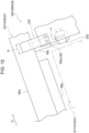
Fig. 7 is a front view illustrating a mounting configuration of the exposure device in the image carrier unit according to the exemplary embodiment of the present disclosure; -
Fig. 8 is a view illustrating a mounting configuration of the exposure device in the image carrier unit according to the exemplary embodiment of the present disclosure, and is as viewed in a direction perpendicular to the projection direction of a projecting member as seen from the front; -
Figs. 9A, 9B are sectional views illustrating the image carrier unit according to the exemplary embodiment of the present disclosure; -
Fig. 10 is a configuration view illustrating the image carrier unit according to the exemplary embodiment of the present disclosure; -
Fig. 11 is a front view illustrating a mounting configuration of the exposure device in the image carrier unit according to the exemplary embodiment of the present disclosure; -
Fig. 12 is a view illustrating a mounting configuration of the exposure device in the image carrier unit according to the exemplary embodiment of the present disclosure, and is as viewed in a direction perpendicular to the projection direction of a projecting member as seen from the front; and -
Figs. 13A, 13B are sectional views illustrating the image carrier unit according to the exemplary embodiment of the present disclosure. - An example of an image carrier unit and an image forming apparatus according to an exemplary embodiment of the present disclosure will be described with reference to
Fig. 1 to Figs. 13A ,13B . Note that arrow H illustrated in the Figures indicates an apparatus up-down direction (vertical direction), arrow W indicates an apparatus width direction (horizontal direction), and arrow D indicates an apparatus depth direction (horizontal direction). Each of the drawings used for the description is schematic. The relationship between the dimensions of each element, and the dimensional ratio of each element illustrated in the drawings do not necessarily correspond to the actual ones. Furthermore, the relationships between the dimensions of each element, and the dimensional ratio of each element between multiple drawings do not necessarily correspond to each other. - An
image forming apparatus 10 according to the exemplary embodiment is an electrophotographic image forming apparatus that forms a toner image on a sheet member P as a recording medium. As illustrated inFig. 1 , theimage forming apparatus 10 includes astorage unit 20, atransport unit 30, an image former 40, and afixing device 50. - As illustrated in
Fig. 1 , thestorage unit 20 includes astorage member 22 that stores sheet members P, and adelivery roller 24 that delivers a sheet member P stored in thestorage member 22 to atransport path 32 for the sheet member P. Thetransport unit 30 includes a plurality oftransport rollers 34 to transport the sheet member P along thetransport path 32. - As illustrated in
Fig. 1 , the image former 40 includes a toner image former 60 that forms a toner image, and atransfer device 70 that transfers the toner image formed by the toner image former 60 to the sheet member P. - The
image forming apparatus 10 includestoner image formers - The toner image former 60Y and the toner image former 60M are basically configurated in the same manner except for the toner to be used. The toner image former 60C and the toner image former 60K are basically configurated in the same manner except for the toner to be used.
- As illustrated in
Fig. 1 ,Fig. 2 , the toner image formers 60C, 60K are arranged side by side along an inclined portion of atransfer belt 71 included in thetransfer device 70. As illustrated inFigs. 1 ,3 , the toner image formers 60Y, 60M are arranged side by side along a horizontal portion of thetransfer belt 71 included in thetransfer device 70. - As illustrated in
Fig. 2 , the toner image formers 60C, 60K includeimage carriers Fig. 2 while being in contact with thetransfer belt 71, andcharging devices image carriers - In addition, the
toner image formers exposure devices image carriers charging devices devices -
Image carrier units image carriers exposure devices - As illustrated in
Fig. 3 , thetoner image formers image carriers Fig. 3 while being in contact with thetransfer belt 71; and chargingdevices image carriers - In addition, the
toner image formers exposure devices image carriers charging devices devices -
Image carrier units image carriers exposure devices image carrier units - As illustrated in
Fig. 1 , thetransfer device 70 includes thetransfer belt 71 as an intermediate transfer body,multiple rollers 72,first transfer rollers 73, asecond transfer roller 76, and aremoval blade 78. - The
transfer belt 71 has an endless form, and is wound on themultiple rollers 72 to have an inverted triangular posture. Thetoner image formers transfer belt 71, and thetoner image formers Fig. 1 ) of thetransfer belt 71 in the apparatus width direction. In addition, rotational drive of at least one of themultiple rollers 72 causes thetransfer belt 71 to circumferentially rotate in arrow B direction. - In the description below, a
roller 72 among themultiple rollers 72, which is disposed to push out an inclined portion of the other side (left side inFig. 1 ) of thetransfer belt 71 in the apparatus width direction is referred to as aroller 72a, and aroller 72 on which a portion of the other side of thetransfer belt 71 in the apparatus width direction is wound is referred to as aroller 72b. - In addition, as illustrated in
Fig. 2 ,Fig. 3 , thefirst transfer rollers 73 are disposed on the opposite side of theimage carrier 61 of each color with respect to thetransfer belt 71. As illustrated inFig. 1 , thesecond transfer roller 76 is disposed on the opposite side of theroller 72a with respect to thetransfer belt 71, and theremoval blade 78 is disposed on the opposite side of theroller 72b with respect to thetransfer belt 71. - In this configuration, the
first transfer rollers 73 transfers a toner image formed in theimage carrier 61 to thetransfer belt 71 at a first transfer position T (seeFig. 2 ,Fig. 3 ) between theimage carrier 61 and thefirst transfer roller 73. Thesecond transfer roller 76 then transfers to the sheet member P, a toner image transferred to thetransfer belt 71, at a second transfer position NT between thetransfer belt 71 and thesecond transfer roller 76. In addition, theremoval blade 78 scrapes off residual toner remaining on thetransfer belt 71 from thetransfer belt 71. - As illustrated in
Fig. 1 , the fixingdevice 50 includes aheating roller 50a that rotates, and apressure roller 50b that is driven to rotate by theheating roller 50a, and presses the sheet member P to theheating roller 50a with the sheet member P interposed between theheating roller 50a and thepressure roller 50b. - Thus, the fixing
device 50 is designed to heat and pressurize the sheet member P with a toner image transferred to fix the toner image onto the sheet member P. The sheet member P with a toner image fixed is designed to be discharged to the outside of ahousing 10a of theimage forming apparatus 10. - Next, the details of the
image carrier units image carrier units image carrier units - Note that part of the
image carrier units image carrier units image carrier units image carrier unit 68C will be described. Similarly, since theimage carrier units image carrier unit 68Y will be described. - As illustrated in
Fig. 4 , theimage carrier unit 68C includes animage carrier 61C that extends in the apparatus depth direction and has a circular cross section, anexposure device 63C, asupport member 80 that rotatably supports theimage carrier 61C, and amounting mechanism 100 that mounts theexposure device 63C on thesupport member 80. The apparatus depth direction is an example of one direction. - In addition, the
image carrier unit 68C includes an adjusting member 86 (seeFig. 6 ) that adjusts the position of theexposure device 63C relative to theimage carrier 61C in a radial direction of theimage carrier 61C. - As illustrated in
Fig. 4 , theexposure device 63C is a LED print head (LPH), and disposed on one side and below theimage carrier 61C in the apparatus width direction as seen in the apparatus depth direction. In other words, theexposure device 63C is disposed diagonally below theimage carrier 61C as seen in the apparatus depth direction. - In addition, the
exposure device 63C is opposed to theimage carrier 61C in a radial direction of theimage carrier 61C, and extends in the apparatus depth direction as illustrated inFig. 5 . Theexposure device 63C includes abody member 66a, and anoptical member 66b which projects from thebody member 66a toward theimage carrier 61C (seeFig. 4 ) and from which exposure light is emitted. - The
body member 66a and theoptical member 66b extend in the apparatus depth direction, and thebody member 66a projects to both sides of theoptical member 66b in the apparatus depth direction. Thebody member 66a has a rectangular cross section, and of thebody member 66a, both-end portions projecting from theoptical member 66b in the apparatus depth direction are provided with a pair of projectingmembers 66c that project toward theimage carrier 61C. Specifically, the projectingmembers 66c are cylindrical, and made of chrome-plated metal, and project along a radial direction of theimage carrier 61C. Note that the projection direction of each projectingmember 66c may be along a radial direction, and it is even better if the projection direction is a radial direction. - As illustrated in
Fig. 6 , the adjustingmember 86 is disposed at both-end portions of theexposure device 63 in the apparatus depth direction. The adjustingmember 86 includes ahemispherical projection 88 that projects from thebody member 66a of theexposure device 63 in a radial direction of theimage carrier 61, and anadjuster 90 including acontact surface 90a which comes into contact with the tip end of theprojection 88. In addition, the adjustingmember 86 includes amover 92 that moves theadjuster 90 in the apparatus depth direction, and an urging member (not illustrated) that urges theexposure device 63 so that the tip end of theprojection 88 comes into contact with thecontact surface 90a. Themover 92 and the urging member are fixed to a frame member (not illustrated) on which thesupport member 80 is mounted. - The
contact surface 90a of theadjuster 90 is inclined with respect to the apparatus depth direction as seen in a circumferential direction of theimage carrier 61. Therefore, it is designed that theexposure device 63 is separated in proximity to theimage carrier 61 by moving theadjuster 90 back and forth in the apparatus depth direction by themover 92. - A pair of
support members 80 are made of aluminum alloy and provided to interpose theimage carrier 61C therebetween in the apparatus depth direction, and are mounted on a frame member which is not illustrated. The pair ofsupport members 80 are symmetric, and have the same configuration, thus in the explanation below, thesupport member 80 disposed on the back side of theimage carrier 61C in the apparatus depth direction will be described. Thesupport member 80 is an example of a formation member. - The
support member 80 rotatably supports theimage carrier 61C, and as illustrated inFig. 7 , aprojection 80a is formed in thesupport member 80, theprojection 80a projecting toward theexposure device 63C as seen in the apparatus depth direction. - In a portion, near the
exposure device 63C, of thesupport member 80, a U-shapedcross-sectional recess 82 with the inside in the apparatus depth direction open is formed extending in a radial direction of theimage carrier 61C. The projectingmembers 66c of theexposure device 63C are stored in therecess 82. - The
recess 82 is constituted by including: atop surface 82a opposed to and spaced from the tip end of the projectingmember 66c in a radial direction of theimage carrier 61C; a pair ofopposed surfaces member 66c in a circumferential direction of theimage carrier 61C; and abottom surface 82d (seeFig. 9A ) opposed to the projectingmembers 66c in the apparatus depth direction. For the convenience of the following description, the surface disposed on the clockwise side of the projectingmember 66c in a circumferential direction of theimage carrier 61C is referred to as anopposed surface 82b, and the surface disposed on the counterclockwise side of the projectingmember 66c in a circumferential direction of theimage carrier 61C is referred to as anopposed surface 82c. - As illustrated in
Fig. 7 , the mountingmechanism 100 includes: a pressingmember 102 that presses aperipheral surface 67 of the projectingmember 66c against theopposed surface 82b; a to-be-pressed member 110 disposed to cover theopposed surface 82b; and an urgingmember 120 mounted on thebody member 66a of theexposure device 63C. - The pressing
member 102 is formed by stacking and bending three pieces of plates made of stainless steel, and presses theperipheral surface 67 of the tip-end side (the upper-end side) portion of the projectingmember 66c of theexposure device 63C to press theperipheral surface 67 of the projectingmember 66c against theopposed surface 82b. - Specifically, as seen in a radial direction of the
image carrier 61C, the pressingmember 102 has a crank shape as illustrated inFig. 9A , and the base-end portion of thepressing member 102 is mounted on thesupport member 80 using a mounting member (symbol is omitted). In addition, at the tip-end portion of thepressing member 102, apressing surface 102a is formed, which comes into contact with theperipheral surface 67 of the projectingmember 66c in a circumferential direction of theimage carrier 61C. Furthermore, in a state where theperipheral surface 67 of the projectingmember 66c and thepressing surface 102a are in contact with each other, the pressingmember 102 is elastically deformed. With this elastic force, the pressingmember 102 presses theperipheral surface 67 of the projectingmember 66c against theopposed surface 82b to an extent to allow theexposure device 63C to move in a radial direction of theimage carrier 61C. - The pressing
member 102 is formed by stacking and bending three pieces of plates made of stainless steel. Thus, the difference in line lengths between inner bending and outer bending is reduced, as compared to when the pressing member is formed by bending one piece of plate made of stainless steel, thus plastic deformation of thepressing member 102 is prevented. - Here, "to an extent to allow the
exposure device 63C to move in a radial direction of theimage carrier 61C" means "to an extent to allow theexposure device 63C to move using the adjustingmember 86 that adjusts the position of theexposure device 63C relative to theimage carrier 61C". - The to-
be-pressed member 110 is formed by bending a plate made of stainless steel, and is disposed to cover theopposed surface 82b from the projectingmember 66c, and mounted on thesupport member 80 by a mounting member (symbol is omitted) as illustrated inFig. 7 ,Fig. 9B . - In the to-
be-pressed member 110, a to-be-pressed section 110a and a to-be-pressed section 110b are formed, which project to the projectingmember 66c from a portion layered on theopposed surface 82b to come into contact with theperipheral surface 67 of the projectingmember 66c. Specifically, the to-be-pressed section 110a and the to-be-pressed section 110b are separated in a radial direction of theimage carrier 61C, and the to-be-pressed section 110b is disposed outward (on the opposite side of the center of theimage carrier 61C) of the to-be-pressed section 110a in a radial direction of theimage carrier 61C. The to-be-pressed section 110a is disposed on the opposite side of thepressing surface 102a of thepressing member 102 with respect to the projectingmember 66c in a circumferential direction of theimage carrier 61C. Note that in this exemplary embodiment, theopposed surface 82b projects along the to-be-pressed section 110a and the to-be-pressed section 110b. - In this configuration, the elastically deformed pressing
member 102 presses theperipheral surface 67 of the projectingmember 66c against theopposed surface 82b via the to-be-pressed member 110. The projectingmember 66c is positioned in a circumferential direction of theimage carrier 61C by the projectingmember 66c coming into contact with three points: thepressing surface 102a of thepressing member 102, the to-be-pressed section 110a of the to-be-pressed member 110, and the to-be-pressed section 110b of the to-be-pressed member 110. In other words, theexposure device 63C is positioned in a circumferential direction of theimage carrier 61C by the projectingmember 66c coming into contact with three points: thepressing surface 102a of thepressing member 102, the to-be-pressed section 110a of the to-be-pressed member 110, and the to-be-pressed section 110b of the to-be-pressed member 110. - Note that regarding the positioning of the
exposure device 63C in the apparatus depth direction, the position of theexposure device 63C in the apparatus depth direction is determined by a positioner (not illustrated) coming into contact with the projectingmember 66c from an inward position in the apparatus depth direction. - The urging
member 120 is formed by bending a plate made of stainless steel, and is mounted on thebody member 66a of theexposure device 63C using a mounting member (symbol is omitted) as illustrated inFig. 7 ,Fig. 8 . Specifically, as seen in a circumferential direction of theimage carrier 61C, the urgingmember 120 extends from thebody member 66a of theexposure device 63C outward in a radial direction ofimage carrier 61C as illustrated inFig. 8 . The base-end portion of the urgingmember 120 is mounted on thebody member 66a from one side (the clockwise side inFig. 7 ) of theimage carrier 61C in a circumferential direction. - The tip-end portion of the urging
member 120 comes into contact with abracket 126 from one side of theimage carrier 61C in a circumferential direction, thebracket 126 being fixed to a frame member (not illustrated) on which thesupport member 80 is mounted. In a state where the tip-end portion of the urgingmember 120 is in contact with thebracket 126, the urgingmember 120 is elastically deformed. With this elastic force, the urgingmember 120 urges theexposure device 63C to the other side (the counterclockwise side inFig. 7 ) of theimage carrier 61C in a circumferential direction. - Here, the sum of a frictional force in a radial direction of the
image carrier 61C generated in theexposure device 63C by the urgingmember 120 urging theexposure device 63C to the other side of theimage carrier 61C in a circumferential direction, and a frictional force in a radial direction of theimage carrier 61C generated in theexposure device 63C by the pressingmember 102 pressing theperipheral surface 67 of the projectingmember 66c against theopposed surface 82b is smaller than the force that causes theexposure device 63C to be moved in a radial direction of theimage carrier 61C using the adjustingmember 86. - That is, even in consideration of the urging force of the urging
member 120 and the pressing force of thepressing member 102, theexposure device 63C can be moved using the adjustingmember 86 that adjusts the position of theexposure device 63C relative to theimage carrier 61C. - In this configuration, for example, even if vibration is applied to the
image carrier unit 68C when being transported, vibration of theexposure device 63C relative to theimage carrier 61C in a circumferential direction of theimage carrier 61C is prevented. - In addition, as illustrated in
Fig. 8 , an area (area j inFig. 8 ) where the urgingmember 120 urges theexposure device 63C, and an area (area k inFig. 8 ) where thepressing member 102 presses the projectingmember 66c overlap at least in part in the apparatus depth direction. Note that it is sufficient that the area j and the area k overlap at least in part in the apparatus depth direction, and it is even better if the entire area k is within the area j in the apparatus depth direction. - In this configuration, distortion in the
exposure device 63C is prevented from occurring, as compared to when the area where the urgingmember 120 urges theexposure device 63C, and the area where thepressing member 102 presses the projectingmember 66c are separated in the apparatus depth direction. - As illustrated in
Fig. 10 , theimage carrier unit 68Y includes: theimage carrier 61Y that extends in the apparatus depth direction and has a circular cross section; theexposure device 63Y; asupport member 180 that rotatably supports theimage carrier 61Y; and amounting mechanism 200 that mounts theexposure device 63Y on thesupport member 180. - In addition, the
image carrier unit 68Y includes the adjusting member 86 (seeFig. 6 ) that adjusts the position of theexposure device 63Y relative to theimage carrier 61Y in a radial direction of theimage carrier 61Y. - As illustrated in
Fig. 10 , theexposure device 63Y is a LED print head (LPH), and disposed on the other side and above theimage carrier 61Y in the apparatus width direction as seen in the apparatus depth direction. In other words, theexposure device 63Y is disposed diagonally above theimage carrier 61Y as seen in the apparatus depth direction. - In addition, the
exposure device 63Y is opposed to theimage carrier 61Y in a radial direction of theimage carrier 61Y, and extends in the apparatus depth direction. Theexposure device 63Y includes thebody member 66a, and theoptical member 66b which projects from thebody member 66a toward theimage carrier 61Y and from which exposure light is emitted. - The
body member 66a and theoptical member 66b extend in the apparatus depth direction, and thebody member 66a projects to both sides of theoptical member 66b in the apparatus depth direction. Thebody member 66a has a rectangular cross section, and of thebody member 66a, both-end portions projecting from theoptical member 66b in the apparatus depth direction are provided with a pair of projectingmembers 66c that project toward theimage carrier 61Y. Specifically, the projectingmembers 66c are cylindrical, and extend along a radial direction of theimage carrier 61Y. - A pair of
support members 180 are made of aluminum alloy and provided to interpose theimage carrier 61Y therebetween in the apparatus depth direction. The pair ofsupport members 180 are symmetric, and have the same configuration, thus in the explanation below, thesupport member 180 disposed on the back side of theimage carrier 61Y in the apparatus depth direction will be described. Thesupport member 180 is an example of a formation member. - The
support member 180 rotatably supports theimage carrier 61Y, and as illustrated inFig. 11 , aprojection 180a is formed in thesupport member 180, theprojection 180a projecting toward theexposure device 63Y as seen in the apparatus depth direction. - In a portion, near the
exposure device 63Y, of thesupport member 180, a U-shapedcross-sectional recess 182 with the inside in the apparatus depth direction open is formed extending in a radial direction of theimage carrier 61Y. The projectingmember 66c of theexposure device 63Y is stored in therecess 182. - The
recess 182 is constituted by including: atop surface 182a opposed to and spaced from the tip end of the projectingmember 66c in a radial direction of theimage carrier 61Y; a pair ofopposed surfaces member 66c in a circumferential direction of theimage carrier 61Y; and abottom surface 182d (seeFig. 13A ) opposed to the projectingmember 66c in the apparatus depth direction. For the convenience of the following description, the surface disposed on the counterclockwise side of the projectingmember 66c in a circumferential direction of theimage carrier 61Y is referred to as anopposed surface 182b, and the surface disposed on the clockwise side of the projectingmember 66c in a circumferential direction of theimage carrier 61Y is referred to as anopposed surface 182c. - As illustrated in
Fig. 11 , the mountingmechanism 200 includes: a pressingmember 202 that presses theperipheral surface 67 of the projectingmember 66c against theopposed surface 182b; a to-be-pressed member 210 disposed to cover theopposed surface 182b; and an urgingmember 220 mounted on theprojection 180a of thesupport member 180. - As illustrated in
Fig. 13A , the pressingmember 202 is constituted by including apressing plate 204 and apressing spring 206. Thepressing plate 204 is formed by bending a plate made of stainless steel. - Specifically, the
pressing plate 204 includes a U-shaped portion as seen in a radial direction of theimage carrier 61Y. The base-end portion of thepressing plate 204 extends from the U-shaped portion to the back side in the apparatus depth direction via a step, and is mounted on thesupport member 180 using a mounting member (symbol is omitted). At the tip-end portion of thepressing plate 204, apressing surface 204a is formed, which comes into contact with theperipheral surface 67 of the projectingmember 66c in a circumferential direction of theimage carrier 61Y. - Furthermore, the
pressing spring 206 is disposed on the opposite side of the projectingmember 66c with respect to thepressing surface 204a. Thepressing spring 206 is a compression coil spring, and is disposed in a state of being compressed in a circumferential direction of theimage carrier 61Y. - In addition, one end of the
pressing spring 206 is in contact with the tip-end portion of thepressing plate 204, and the base-end of thepressing spring 206 is supported by a support surface 180b formed on thesupport member 180. Furthermore, thepressing spring 206 is elastically deformed in a state where thepressing spring 206 is interposed between thepressing plate 204 and the support surface 180b. With this elastic force, the pressingmember 202 presses theperipheral surface 67 of the projectingmember 66c against theopposed surface 182b to an extent to allow theexposure device 63Y to move in a radial direction of theimage carrier 61Y. - Here, "to an extent to allow the
exposure device 63Y to move in a radial direction of theimage carrier 61Y" means "to an extent to allow theexposure device 63Y to move using the adjustingmember 86 that adjusts the position of theexposure device 63Y relative to theimage carrier 61Y". - The to-
be-pressed member 210 is formed by bending a plate made of stainless steel, and is disposed to cover theopposed surface 182b from the projectingmember 66c, and mounted on thesupport member 180 by a mounting member (not illustrated) as illustrated inFig. 11 ,Fig. 13B . - In the to-
be-pressed member 210, a to-be-pressed section 210a and a to-be-pressed section 210b are formed, which project to the projectingmember 66c from a portion layered on theopposed surface 182b to come into contact with theperipheral surface 67 of the projectingmember 66c. Specifically, the to-be-pressed section 210a and the to-be-pressed section 210b are separated in a radial direction of theimage carrier 61Y, and the to-be-pressed section 210b is disposed outward (on the opposite side of the center of theimage carrier 61Y) of the to-be-pressed section 210a in a radial direction of theimage carrier 61Y. The to-be-pressed section 210a is disposed on the opposite side of thepressing surface 204a of thepressing plate 204 with respect to the projectingmember 66c in a circumferential direction of theimage carrier 61Y. Note that in this exemplary embodiment, theopposed surface 182b projects along the to-be-pressed section 210a and the to-be-pressed section 210b. - In this configuration, the pressing
member 202 in which thepressing spring 206 is in a compressed state presses theperipheral surface 67 of the projectingmember 66c against theopposed surface 182b via the to-be-pressed member 210. The projectingmember 66c is positioned in a circumferential direction of theimage carrier 61Y by the projectingmember 66c coming into contact with three points: thepressing surface 204a of thepressing plate 204, the to-be-pressed section 210a of the to-be-pressed member 210, and the to-be-pressed section 210b of the to-be-pressed member 210. In other words, theexposure device 63Y is positioned in a circumferential direction of theimage carrier 61Y by the projectingmember 66c coming into contact with three points: thepressing surface 204a of thepressing plate 204, the to-be-pressed section 210a of the to-be-pressed member 210, and the to-be-pressed section 210b of the to-be-pressed member 210. - Note that regarding the positioning of the
exposure device 63Y in the apparatus depth direction, the position of theexposure device 63Y in the apparatus depth direction is determined by a positioner coming into contact with the projectingmember 66c from an inward position in the apparatus depth direction. - The urging
member 220 is formed by bending a plate made of stainless steel, and is mounted on theprojection 180a of thesupport member 180 by a mounting member (symbol is omitted) as illustrated inFig. 11 ,Fig. 12 . Specifically, as seen in a circumferential direction of theimage carrier 61Y, the urgingmember 220 extends from theprojection 180a of thesupport member 180 outward in a radial direction ofimage carrier 61Y as illustrated inFig. 12 . The base-end portion of the urgingmember 220 is mounted on theprojection 180a of thesupport member 180 from the other side (the counterclockwise side inFig. 10 ) of theimage carrier 61Y in a circumferential direction using a mounting member (symbol is omitted). - The tip-end portion of the urging
member 220 comes into contact with thebody member 66a of theexposure device 63Y from the other side of theimage carrier 61Y in a circumferential direction. In a state where the tip-end portion of the urgingmember 220 is in contact with thebody member 66a of theexposure device 63Y, the urgingmember 220 is elastically deformed. With this elastic force, the urgingmember 220 urges theexposure device 63Y to the other side (the counterclockwise side inFig. 11 ) of theimage carrier 61Y in a circumferential direction. - Here, the sum of a frictional force in a radial direction of the
image carrier 61Y generated in theexposure device 63Y by the urgingmember 220 urging theexposure device 63Y to the other side of theimage carrier 61Y in a circumferential direction, and a frictional force in a radial direction of theimage carrier 61Y generated in theexposure device 63Y by the pressingmember 202 pressing theperipheral surface 67 of the projectingmember 66c against theopposed surface 182b is smaller than the force which causes theexposure device 63Y to be moved in a radial direction of theimage carrier 61Y using the adjustingmember 86. - That is, even in consideration of the urging force of the urging
member 220 and the pressing force of thepressing member 202, theexposure device 63Y can be moved using the adjustingmember 86 that adjusts the position of theexposure device 63Y relative to theimage carrier 61Y. - In this configuration, for example, even if vibration is applied to the
image carrier unit 68Y when being transported, vibration of theexposure device 63Y relative to theimage carrier 61Y in a circumferential direction of theimage carrier 61Y is prevented. - In addition, as illustrated in
Fig. 12 , an area (area m inFig. 12 ) where the urgingmember 220 urges theexposure device 63Y, and an area (area n inFig. 12 ) where thepressing member 202 presses the projectingmember 66c overlap at least in part in the apparatus depth direction. Note that it is sufficient that the area m and the area n overlap at least in part in the apparatus depth direction, and it is even better if the entire area n is within the area m in the apparatus depth direction. - In this configuration, distortion in the
exposure device 63Y is prevented from occurring, as compared to when the area where the urgingmember 220 urges theexposure device 63Y, and the area where thepressing member 202 presses the projectingmember 66c are separated in the apparatus depth direction. - As described above, in the
image carrier units member 102 presses theperipheral surface 67 of the projectingmember 66c against theopposed surface 82b in a circumferential direction of theimage carriers exposure devices image carrier units exposure devices image carriers exposure devices image carriers - In the
image carrier units member 202 presses theperipheral surface 67 of the projectingmember 66c against theopposed surface 182b in a circumferential direction of theimage carriers exposure devices image carrier units exposure devices image carriers exposure devices image carriers - In the
image carrier units be-pressed member 110 mounted on thesupport member 80 covers a portion of theopposed surface 82b, the portion being pressed by theperipheral surface 67 of the projectingmember 66c. Thus, thesupport member 80 is prevented from wear, as compared to when the projecting member is directly pressed against the opposed surface of the support member. - In addition, in the
image carrier units be-pressed member 210 mounted on thesupport member 180 covers a portion of theopposed surface 182b, the portion being pressed by theperipheral surface 67 of the projectingmember 66c. Thus, thesupport member 180 is prevented from wear, as compared to when the projecting member is directly pressed against the opposed surface of the support member. - In the
image carrier units be-pressed sections peripheral surface 67 of the projectingmember 66c is pressed are provided in the to-be-pressed member 110 at two locations separated in a radial direction of theimage carriers exposure devices image carriers - In the
image carrier units be-pressed sections peripheral surface 67 of the projectingmember 66c is pressed are provided in the to-be-pressed member 210 at two locations separated in a radial direction of theimage carriers exposure devices image carriers - In the
image carrier units member 120 urges theexposure devices image carriers pressing member 102 presses the projectingmember 66c, in a radial direction of theimage carriers exposure devices image carriers image carrier units - In the
image carrier units member 220 urges theexposure devices image carriers pressing member 202 presses the projectingmember 66c, in a radial direction of theimage carriers exposure devices image carriers image carrier units - In the
image carrier units member 120 urges theexposure devices pressing member 102 presses the projectingmember 66c overlap at least in part in the apparatus depth direction. Thus, distortion in theexposure devices - In the
image carrier units member 220 urges theexposure devices pressing member 202 presses the projectingmember 66c overlap at least in part in the apparatus depth direction. Thus, distortion in theexposure devices - In the
image forming apparatus 10, as compared to when the image carrier unit is provided in which the projectingmember 66c that projects to theimage carrier 61 is fitted to the support member by a clearance fit, the positional accuracy of theexposure device 63 is improved, thus the output image quality is improved. - Note that although the present disclosure has been described in detail through a specific exemplary embodiment, the present disclosure is not limited to those exemplary embodiment, and it is apparent to those skilled in the art that various other embodiments are possible within the scope of the present disclosure. For example, in the above exemplary embodiment, the
image carrier unit 68 includes the to-be-pressed members image carrier unit 68 may not include a to-be-pressed member. However, in this case, the effect achieved by providing the to-be-pressed members - In the above exemplary embodiment, the
support members support members - In the above exemplary embodiment, the to-
be-pressed sections be-pressed sections - In the above exemplary embodiment, the to-
be-pressed sections be-pressed sections - In the above exemplary embodiment, the urging
members members - The urging member and the pressing member may be integrated although it has not been specifically mentioned in the above exemplary embodiment.
- The foregoing description of the exemplary embodiments of the present disclosure has been provided for the purposes of illustration and description. It is not intended to be exhaustive or to limit the disclosure to the precise forms disclosed. Obviously, many modifications and variations will be apparent to practitioners skilled in the art. The embodiments were chosen and described in order to best explain the principles of the disclosure and its practical applications, thereby enabling others skilled in the art to understand the disclosure for various embodiments and with the various modifications as are suited to the particular use contemplated. It is intended that the scope of the disclosure be defined by the following claims and their equivalents.
-
- (((1))) An image carrier unit comprising:
- an image carrier having a circular cross-section and extending in one direction;
- an exposure device that radiates exposure light to the image carrier, the exposure device extending in the one direction and being opposed to the image carrier in a radial direction of the image carrier;
- a projecting member that is provided at both-end portions of the exposure device in the one direction, and projects to the image carrier along the radial direction;
- a formation member including an opposed surface that is opposed to a peripheral surface of the projecting member in a circumferential direction of the image carrier;
- a pressing member that presses the projecting member in the circumferential direction to press the peripheral surface of the projecting member against the opposed surface; and
- an adjusting member that adjusts a position of the exposure device relative to the image carrier by moving the exposure device in the radial direction with the projecting member pressed by the pressing member.
- (((2))) The image carrier unit according to (((1))),
- wherein the formation member is made of aluminum or aluminum alloy,
- the projecting member is made of steel, and
- the image carrier unit includes a stainless steel to-be-pressed member that is mounted on the formation member, and that covers a portion of the opposed surface, the portion against which the peripheral surface of the projecting member is pressed.
- (((3))) The image carrier unit according to (((2))),
wherein the to-be-pressed member includes a plurality of to-be-pressed sections, against which the peripheral surface of the projecting member is pressed, the plurality of to-be-pressed sections being separated along the radial direction. - (((4))) The image carrier unit according to any one of (((1))) to (((3))), further comprising
an urging member that urges the exposure device in the circumferential direction of the image carrier at a position separated along the radial direction from a position where the pressing member presses the projecting member. - (((5))) The image carrier unit according to (((4))),
wherein an area where the urging member urges the exposure device in the one direction, and an area where the pressing member presses the projecting member in the one direction overlap at least in part in the one direction. - (((6))) An image forming apparatus comprising:
- the image carrier unit according to any one of (((1))) to (((5))); and
- a transfer device that transfers an image formed in the image carrier of the image carrier unit to a recording medium.
- With the image carrier unit according to (((1))), the positional accuracy of the exposure device in a circumferential direction of the image carrier can be improved while allowing the exposure device to be moved in a radial direction of the image carrier, as compared to when the projecting member provided at both end portions of the exposure device is fitted to the support member by a clearance fit.
- With the image carrier unit according to (((2))), the formation member can be prevented from wear, as compared to when the projecting member is directly pressed against the opposed surface of the support member.
- With the image carrier unit according to (((3))), the positional accuracy of the exposure device in a circumferential direction of the image carrier can be improved, as compared to when a to-be-pressed section is provided only at one location in a radial direction.
- With the image carrier unit according to (((4))), vibration of the exposure device relative to the image carrier can be prevented, as compared to when the exposure device in an area other than the portion pressed by the pressing member is in no load state in a circumferential direction of the image carrier.
- With the image carrier unit according to (((5))), a distortion force in the exposure device is prevented from occurring, as compared to when the area where the urging member urges the exposure device, and the area where the pressing member presses the projecting member are separated in the apparatus depth direction.
- With the image carrier unit according to (((6))), the output image quality can be improved, as compared to when the image carrier unit is provided in which the projecting member that projects to the image carrier is fitted to the support member by a clearance fit.
Claims (6)
- An image carrier unit comprising:an image carrier having a circular cross-section and extending in one direction;an exposure device that radiates exposure light to the image carrier, the exposure device extending in the one direction and being opposed to the image carrier in a radial direction of the image carrier;a projecting member that is provided at both-end portions of the exposure device in the one direction, and projects to the image carrier along the radial direction;a formation member including an opposed surface that is opposed to a peripheral surface of the projecting member in a circumferential direction of the image carrier;a pressing member that presses the projecting member in the circumferential direction to press the peripheral surface of the projecting member against the opposed surface; andan adjusting member that adjusts a position of the exposure device relative to the image carrier by moving the exposure device in the radial direction with the projecting member pressed by the pressing member.
- The image carrier unit according to claim 1,wherein the formation member is made of aluminum or aluminum alloy,the projecting member is made of steel, andthe image carrier unit includes a stainless steel to-be-pressed member that is mounted on the formation member, and that covers a portion of the opposed surface, the portion against which the peripheral surface of the projecting member is pressed.
- The image carrier unit according to claim 2,
wherein the to-be-pressed member includes a plurality of to-be-pressed sections, against which the peripheral surface of the projecting member is pressed, the plurality of to-be-pressed sections being separated along the radial direction. - The image carrier unit according to any one of claims 1 to 3, further comprising
an urging member that urges the exposure device in the circumferential direction of the image carrier at a position separated along the radial direction from a position where the pressing member presses the projecting member. - The image carrier unit according to claim 4,
wherein an area where the urging member urges the exposure device in the one direction, and an area where the pressing member presses the projecting member in the one direction overlap at least in part in the one direction. - An image forming apparatus comprising:the image carrier unit according to any one of claims 1 to 5; anda transfer device that transfers an image formed in the image carrier of the image carrier unit to a recording medium.
Applications Claiming Priority (1)
| Application Number | Priority Date | Filing Date | Title |
|---|---|---|---|
| JP2023051239A JP2024140210A (en) | 2023-03-28 | 2023-03-28 | Image carrier unit Image forming apparatus |
Publications (1)
| Publication Number | Publication Date |
|---|---|
| EP4439184A1 true EP4439184A1 (en) | 2024-10-02 |
Family
ID=87554656
Family Applications (1)
| Application Number | Title | Priority Date | Filing Date |
|---|---|---|---|
| EP23189260.5A Pending EP4439184A1 (en) | 2023-03-28 | 2023-08-02 | Image carrier unit and image forming apparatus |
Country Status (4)
| Country | Link |
|---|---|
| US (1) | US20240329559A1 (en) |
| EP (1) | EP4439184A1 (en) |
| JP (1) | JP2024140210A (en) |
| CN (1) | CN118732436A (en) |
Citations (6)
| Publication number | Priority date | Publication date | Assignee | Title |
|---|---|---|---|---|
| JP3457786B2 (en) * | 1995-12-25 | 2003-10-20 | カシオ電子工業株式会社 | Image forming device |
| JP2005022259A (en) | 2003-07-02 | 2005-01-27 | Sharp Corp | Focus adjustment apparatus and image forming apparatus |
| US20070126852A1 (en) * | 2005-12-05 | 2007-06-07 | Sharp Kabushiki Kaisha | Image forming apparatus and adjusting method of image forming apparatus |
| US20080145103A1 (en) * | 2006-12-08 | 2008-06-19 | Fuji Xerox Co., Ltd. | Image forming apparatus, exposure apparatus, image holder, image forming method, and exposing method |
| US10429760B2 (en) * | 2016-12-15 | 2019-10-01 | Brother Kogyo Kabushiki Kaisha | Image forming apparatus |
| US20230062126A1 (en) * | 2021-08-25 | 2023-03-02 | Fujifilm Business Innovation Corp. | Exposure device and image forming apparatus |
-
2023
- 2023-03-28 JP JP2023051239A patent/JP2024140210A/en active Pending
- 2023-07-28 US US18/361,094 patent/US20240329559A1/en active Pending
- 2023-08-02 EP EP23189260.5A patent/EP4439184A1/en active Pending
- 2023-08-09 CN CN202311003980.6A patent/CN118732436A/en active Pending
Patent Citations (6)
| Publication number | Priority date | Publication date | Assignee | Title |
|---|---|---|---|---|
| JP3457786B2 (en) * | 1995-12-25 | 2003-10-20 | カシオ電子工業株式会社 | Image forming device |
| JP2005022259A (en) | 2003-07-02 | 2005-01-27 | Sharp Corp | Focus adjustment apparatus and image forming apparatus |
| US20070126852A1 (en) * | 2005-12-05 | 2007-06-07 | Sharp Kabushiki Kaisha | Image forming apparatus and adjusting method of image forming apparatus |
| US20080145103A1 (en) * | 2006-12-08 | 2008-06-19 | Fuji Xerox Co., Ltd. | Image forming apparatus, exposure apparatus, image holder, image forming method, and exposing method |
| US10429760B2 (en) * | 2016-12-15 | 2019-10-01 | Brother Kogyo Kabushiki Kaisha | Image forming apparatus |
| US20230062126A1 (en) * | 2021-08-25 | 2023-03-02 | Fujifilm Business Innovation Corp. | Exposure device and image forming apparatus |
Also Published As
| Publication number | Publication date |
|---|---|
| US20240329559A1 (en) | 2024-10-03 |
| CN118732436A (en) | 2024-10-01 |
| JP2024140210A (en) | 2024-10-10 |
Similar Documents
| Publication | Publication Date | Title |
|---|---|---|
| KR101764202B1 (en) | Fusing device and image forming apparatus having the same | |
| US7840159B2 (en) | Image-forming device having a positioning structure | |
| US8712302B2 (en) | Pressure-applying member, fixing device, and image forming apparatus | |
| US7869750B2 (en) | Image forming apparatus with a phase of a first load torque substantially opposite to a phase of a second load torque | |
| US9239539B2 (en) | Developing device and layer thickness regulating member | |
| US20110052282A1 (en) | Fixing device and image forming apparatus incorporating same | |
| US7406287B2 (en) | Fixing device and image forming apparatus provided with fixing device | |
| US7623809B2 (en) | Image forming apparatus having belt unit | |
| US20090056484A1 (en) | Image forming apparatus | |
| US8670016B2 (en) | Exposure device and image forming device having a fixing member for fixing an optical system member | |
| KR20120045888A (en) | Fusing device and image forming apparatus having the same | |
| KR20160146017A (en) | Image Fixing Apparatus and Image Forming Apparatus using the same | |
| US9141020B2 (en) | Charger positioning adjuster and image forming apparatus incorporating same | |
| CN100445893C (en) | Fixing device and image forming device | |
| CN102411291B (en) | Driving arrangement and image processing system | |
| JP3613919B2 (en) | Fixing device | |
| KR20160078949A (en) | Fusing device and image forming apparatus having the same | |
| JP5936370B2 (en) | Cleaning device, process cartridge, image forming apparatus | |
| US20240329559A1 (en) | Image carrier unit and image forming apparatus | |
| US20090226210A1 (en) | Image-forming device | |
| JP5117777B2 (en) | Lubricant application device, process cartridge, image forming device | |
| EP4141572B1 (en) | Exposure device and image forming apparatus | |
| JP5028838B2 (en) | Image fixing apparatus and image forming apparatus | |
| JP4483345B2 (en) | Image forming apparatus | |
| US8155559B2 (en) | Image-forming device |
Legal Events
| Date | Code | Title | Description |
|---|---|---|---|
| PUAI | Public reference made under article 153(3) epc to a published international application that has entered the european phase |
Free format text: ORIGINAL CODE: 0009012 |
|
| STAA | Information on the status of an ep patent application or granted ep patent |
Free format text: STATUS: THE APPLICATION HAS BEEN PUBLISHED |
|
| AK | Designated contracting states |
Kind code of ref document: A1 Designated state(s): AL AT BE BG CH CY CZ DE DK EE ES FI FR GB GR HR HU IE IS IT LI LT LU LV MC ME MK MT NL NO PL PT RO RS SE SI SK SM TR |
|
| STAA | Information on the status of an ep patent application or granted ep patent |
Free format text: STATUS: REQUEST FOR EXAMINATION WAS MADE |
|
| 17P | Request for examination filed |
Effective date: 20241112 |
|
| RBV | Designated contracting states (corrected) |
Designated state(s): AL AT BE BG CH CY CZ DE DK EE ES FI FR GB GR HR HU IE IS IT LI LT LU LV MC ME MK MT NL NO PL PT RO RS SE SI SK SM TR |
|
| GRAP | Despatch of communication of intention to grant a patent |
Free format text: ORIGINAL CODE: EPIDOSNIGR1 |
|
| STAA | Information on the status of an ep patent application or granted ep patent |
Free format text: STATUS: GRANT OF PATENT IS INTENDED |