EP4439113A1 - Simulating device for multiple parallel antenna signals, corresponding system and method - Google Patents
Simulating device for multiple parallel antenna signals, corresponding system and method Download PDFInfo
- Publication number
- EP4439113A1 EP4439113A1 EP23164870.0A EP23164870A EP4439113A1 EP 4439113 A1 EP4439113 A1 EP 4439113A1 EP 23164870 A EP23164870 A EP 23164870A EP 4439113 A1 EP4439113 A1 EP 4439113A1
- Authority
- EP
- European Patent Office
- Prior art keywords
- radio frequency
- output
- frequency signal
- signals
- antenna
- Prior art date
- Legal status (The legal status is an assumption and is not a legal conclusion. Google has not performed a legal analysis and makes no representation as to the accuracy of the status listed.)
- Pending
Links
- 238000000034 method Methods 0.000 title claims description 11
- 238000012545 processing Methods 0.000 claims abstract description 50
- 238000004364 calculation method Methods 0.000 claims description 15
- 238000004088 simulation Methods 0.000 claims description 15
- 230000007274 generation of a signal involved in cell-cell signaling Effects 0.000 claims description 6
- 238000012360 testing method Methods 0.000 description 11
- 238000013507 mapping Methods 0.000 description 6
- 230000003044 adaptive effect Effects 0.000 description 4
- 238000004891 communication Methods 0.000 description 3
- 238000013519 translation Methods 0.000 description 3
- 230000004075 alteration Effects 0.000 description 1
- 230000001419 dependent effect Effects 0.000 description 1
- 238000011161 development Methods 0.000 description 1
- 230000018109 developmental process Effects 0.000 description 1
- 238000010586 diagram Methods 0.000 description 1
- 238000005259 measurement Methods 0.000 description 1
- 238000012986 modification Methods 0.000 description 1
- 230000004048 modification Effects 0.000 description 1
- 230000009466 transformation Effects 0.000 description 1
- 230000001131 transforming effect Effects 0.000 description 1
Images



Classifications
-
- G—PHYSICS
- G01—MEASURING; TESTING
- G01S—RADIO DIRECTION-FINDING; RADIO NAVIGATION; DETERMINING DISTANCE OR VELOCITY BY USE OF RADIO WAVES; LOCATING OR PRESENCE-DETECTING BY USE OF THE REFLECTION OR RERADIATION OF RADIO WAVES; ANALOGOUS ARRANGEMENTS USING OTHER WAVES
- G01S7/00—Details of systems according to groups G01S13/00, G01S15/00, G01S17/00
- G01S7/02—Details of systems according to groups G01S13/00, G01S15/00, G01S17/00 of systems according to group G01S13/00
- G01S7/40—Means for monitoring or calibrating
- G01S7/4052—Means for monitoring or calibrating by simulation of echoes
- G01S7/4082—Means for monitoring or calibrating by simulation of echoes using externally generated reference signals, e.g. via remote reflector or transponder
- G01S7/4086—Means for monitoring or calibrating by simulation of echoes using externally generated reference signals, e.g. via remote reflector or transponder in a calibrating environment, e.g. anechoic chamber
-
- H—ELECTRICITY
- H04—ELECTRIC COMMUNICATION TECHNIQUE
- H04B—TRANSMISSION
- H04B17/00—Monitoring; Testing
- H04B17/0082—Monitoring; Testing using service channels; using auxiliary channels
- H04B17/0087—Monitoring; Testing using service channels; using auxiliary channels using auxiliary channels or channel simulators
-
- G—PHYSICS
- G01—MEASURING; TESTING
- G01S—RADIO DIRECTION-FINDING; RADIO NAVIGATION; DETERMINING DISTANCE OR VELOCITY BY USE OF RADIO WAVES; LOCATING OR PRESENCE-DETECTING BY USE OF THE REFLECTION OR RERADIATION OF RADIO WAVES; ANALOGOUS ARRANGEMENTS USING OTHER WAVES
- G01S7/00—Details of systems according to groups G01S13/00, G01S15/00, G01S17/00
- G01S7/02—Details of systems according to groups G01S13/00, G01S15/00, G01S17/00 of systems according to group G01S13/00
- G01S7/40—Means for monitoring or calibrating
- G01S7/4052—Means for monitoring or calibrating by simulation of echoes
- G01S7/4082—Means for monitoring or calibrating by simulation of echoes using externally generated reference signals, e.g. via remote reflector or transponder
- G01S7/4095—Means for monitoring or calibrating by simulation of echoes using externally generated reference signals, e.g. via remote reflector or transponder the external reference signals being modulated, e.g. rotating a dihedral reflector or modulating a transponder for simulation of a Doppler echo
-
- H—ELECTRICITY
- H04—ELECTRIC COMMUNICATION TECHNIQUE
- H04B—TRANSMISSION
- H04B17/00—Monitoring; Testing
- H04B17/30—Monitoring; Testing of propagation channels
- H04B17/391—Modelling the propagation channel
- H04B17/3912—Simulation models, e.g. distribution of spectral power density or received signal strength indicator [RSSI] for a given geographic region
Definitions
- the invention relates to a simulating device for multiple parallel antenna signals, a system comprising such a device and a plurality of radio frequency signal generators, and a method for simulating multiple antenna signals in parallel.
- a simulating device for multiple parallel antenna signals a system comprising such a device and a plurality of radio frequency signal generators, and a method for simulating multiple antenna signals in parallel for performing measurements with respect to such applications in order to verify their correct functioning.
- US 2022/0179044 A1 relates to an apparatus for generating an emulated radar reflection signal of a target moving at a relative velocity.
- the apparatus includes a radar detector, an emulation transmitter, and a processor.
- the radar detector is configured to detect radar chirps emitted by a device under test (DUT), where the chirps are emitted at random time intervals.
- the emulation transmitter is configured to generate emulated radar reflection signals of the target being emulated.
- the processor is configured to generate control signals at intervals corresponding to the random time intervals at which the radar chirps are emitted by the DUT, where each control signal controls the emulation transmitter to generate a radar reflection signal.
- a relative phase of the control signals is adjusted according to a duration of each of the random time intervals between successive chirps and a magnitude and sign of the relative velocity of the target.
- a simulating device for multiple parallel antenna signals a system comprising such a device and a plurality of radio frequency signal generators, and a method for simulating multiple antenna signals in parallel, thereby allowing for adapting and tailoring the solution offered to the users based on their individual simulation needs in a highly flexible and particularly efficient manner.
- a simulating device for multiple parallel antenna signals comprises at least one source signal terminal, an output processing stage for processing in parallel the at least one source signal with multiple parameters, each specific for one antenna of the multiple antennas, thus producing multiple antenna-specific output signals, and a plurality of output terminals, each of which being supplied with one of the multiple antenna-specific output signals, for supplying a plurality of radio frequency signal generators generating a plurality of simulated radio frequency signals.
- simulation can be adapted and/or tailored to desired simulation requirements in a highly flexible and particularly efficient manner.
- the device can allow for a scalable number of radio frequency outputs and/or a scalable pulse rate and/or a scalable pulse-on-pulse density and/or an adaptive hopping bandwidth and/or an intelligent pulse distribution.
- the device further comprises an input processing stage converting the data in the signal received from the at least one source signal terminal and distributing it to the output processing stage.
- the corresponding input signal can be translated.
- the output processing stage comprises a plurality of parallel server units, one server unit per radio frequency signal generator or one server unit per several radio frequency signal generators.
- the server units and/or the input processing stage can abstract the radio frequency signal generators according to their functionality and split the corresponding input signal in such a way that a complex signal and/or scenario can be represented especially at the output or outputs, respectively, of the radio frequency signal generators.
- the simulated radio frequency signals are radar pulses and/or navigation signals.
- flexibility can further be increased.
- the parameters include at least one of antenna characteristics and/or antenna location.
- inefficiencies can further be reduced.
- the at least one source signal terminal is configured to receive specific data from at least one database or databases, exemplarily for radar signals.
- the at least one source signal terminal is especially configured to form the at least one source signal on the basis of the specific data.
- efficiency can further be increased.
- the at least one source signal terminal comprises information which radio frequency signal generator has which abilities.
- said information can efficiently be gathered with the aid of the output processing stage especially from the radio frequency signal generators.
- said information can be manually configured or requested by the parallel server units of the output processing stage from the radio frequency signal generators.
- the input processing stage is configured to perform at least one port agnostic calculation, especially at least one output terminal agnostic calculation.
- at least one port agnostic calculation especially at least one output terminal agnostic calculation.
- the at least one port agnostic calculation comprises at least one of receiver properties, receiver movement, receiver velocity, doppler shift, signal attenuation, or any combination thereof.
- receiver properties for example, inefficiencies can further be reduced.
- an input signal to the source signal terminal or an input server, respectively has the foregoing information already incorporated.
- the source signal terminal or the input server, respectively does not need to do those particular calculations again but it can do it especially in the case that the input signal does not account for them.
- a multiple antenna signal generation system comprises a simulation device according to the first aspect of the invention or any implementation form thereof, respectively, and a plurality of radio frequency signal generators connected to the output terminals of the simulating device, each radio frequency signal generator generating one or more output signals simulating antenna signals.
- simulation can be adapted and/or tailored to desired simulation requirements in a highly flexible and particularly efficient manner.
- the system can allow for a scalable number of radio frequency outputs and/or a scalable pulse rate and/or a scalable pulse-on-pulse density and/or an adaptive hopping bandwidth and/or an intelligent pulse distribution.
- the frequency range can also be flexible.
- one radio frequency signal generator may simulate from 18 GHz to 20 GHz and another one from 28 GHz to 30 GHz.
- the source signal terminal or an input server, respectively, can intelligently assign the respective pulses to the corresponding output especially based on the corresponding simulation scenario.
- an input stage, especially the input processing stage, of the simulating device distributes the converted data to the parallel server units of the output processing stage in a manner, exemplarily as to the bandwidth, taking into account characteristics of the radio frequency signal generator supplied by the respective server unit and/or the plurality of output terminals.
- said characteristics can efficiently be gathered with the aid of the output processing stage or the server units, respectively, especially from the respective radio frequency signal generator.
- said characteristics can be manually configured or requested by the server units of the output processing stage from the radio frequency signal generators.
- the one or more output signals represent a respective realistic antenna output and/or input signal.
- efficiency can further be increased.
- each radio frequency signal generator is configured to simulate a hopping range up to a certain bandwidth.
- a further radio frequency signal generator can be added via a combiner if a wider hopping bandwidth is desired, thereby increasing both flexibility and efficiency.
- each radio frequency signal generator is configured with an interface to accommodate several base band units, especially several base band boards.
- a based band unit or base band board, respectively can be configured to be coupled, especially detachably coupled, to the respective radio frequency signal generator or the corresponding interface thereof, respectively, which leads to an increased flexibility and efficiency.
- a method for simulating multiple antenna signals in parallel comprises the steps of providing at least one source signal, converting the source signal, processing in parallel the at least one converted source signal with multiple parameters, each specific for one antenna of the multiple antennas, thus producing multiple antenna-specific output signals, and supplying the multiple antenna-specific output signals to a plurality of radio frequency signal generators generating a plurality of simulated radio frequency signals.
- simulation can be adapted and/or tailored to desired simulation requirements in a highly flexible and particularly efficient manner.
- the method can allow for a scalable number of radio frequency outputs and/or a scalable pulse rate and/or a scalable pulse-on-pulse density and/or an adaptive hopping bandwidth and/or an intelligent pulse distribution.
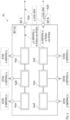
- FIG. 1 a block diagram of an exemplary embodiment 10 of a simulating device for multiple parallel antenna signals according to the first aspect of the invention in combination with an exemplary embodiment 20 of a system according to the second aspect of the invention is illustrated.
- the simulating device 10 comprises at least one source signal terminal, exemplarily the source signal terminal 11, an output processing stage 12 for processing in parallel the at least one source signal with multiple parameters, each specific for one antenna of the multiple antennas, thus producing multiple antenna-specific output signals, and a plurality of output terminals 13, each of which being supplied with one of the multiple antenna-specific output signals, for supplying a plurality of radio frequency signal generators, exemplarily the four radio frequency signal generators 21a, 21b, 21c, 21d, generating a plurality of simulated radio frequency signals.
- the device 10 further comprises an input processing stage 14 converting the data in the signal received from the at least one source signal terminal 11 and distributing it to the output processing stage 12.
- the output processing stage 12 comprises a plurality of parallel server units, one server unit per radio frequency signal generator or one server unit per several radio frequency signal generators.
- the simulated radio frequency signals may preferably be radar pulses and/or navigation signals.
- the above-mentioned parameters include at least one of antenna characteristics and/or antenna location.
- source signal terminal 11 is configured to receive specific data from at least one database or databases, exemplarily for radar signals.
- the source signal terminal 11 is especially configured to form the at least one source signal on the basis of the specific data.
- the source signal terminal 11 comprises information which radio frequency signal generator has which abilities.
- the input processing stage 14 is configured to perform at least one port agnostic calculation, especially at least one output terminal agnostic calculation.
- the at least one port agnostic calculation may preferably comprise at least one of receiver properties, receiver movement, receiver velocity, doppler shift, signal attenuation, or any combination thereof.
- an input signal to the source signal terminal 11 or the input processing stage 14, respectively has the foregoing information already incorporated.
- the source signal terminal 11 or the input processing stage 14, respectively does not need to do those particular calculations again but it can do it especially in the case that the input signal does not account for them.
- Fig. 1 also depicts an exemplary embodiment 20 of the multiple antenna signal generation system.
- Said system 20 comprises the simulation device 10 and a plurality of radio frequency signal generators, exemplarily the four radio frequency signal generators 21a, 21b, 21c, 21d, connected to the output terminals 13 of the simulating device 10, each radio frequency signal generator 21a, 21b, 21c, 21d generating one or more output signals simulating antenna signals.
- the output processing stage 12 comprises a plurality of parallel server units, one server unit per radio frequency signal generator or one server unit per several radio frequency signal generators
- an input stage, exemplarily the input processing stage 14, of the simulating device 10 distributes the converted data to the parallel server units of the output stage 12 in a manner, exemplarily as to the bandwidth, taking into account characteristics of the radio frequency signal generator supplied by the respective server unit and/or the plurality of output terminals 13.
- the one or more output signals represent a respective realistic antenna output and/or input signal.
- each radio frequency signal generator is configured to simulate a hopping range up to a certain bandwidth.
- each radio frequency signal generator may preferably be configured with an interface to accommodate several base band units, especially several base band boards.
- the source signal terminal 11 is connected to the output processing stage 12 especially via the input processing stage 14 if present.
- the output processing stage 12 is exemplarily connected to the plurality of output terminals 13.
- said plurality of output terminals 13 is exemplarily connected to the plurality of radio frequency signal generators 21a, 21b, 21c, 21d.
- FIG. 2 a further exemplary embodiment 30 of the inventive simulating device in combination with a further exemplary embodiment of the inventive system 40 is depicted.
- the device 30 comprises an input server unit 31.
- said input server unit 31 it is noted that the explanations regarding the source signal terminal 11 above can additionally or alternatively apply for said input server unit 31, and vice versa. This can analogously apply for element 71 of Fig. 6 , and vice versa.
- the source signal terminal 11 may especially comprise or be the input server unit 31 or element 71, respectively.
- Said input server unit 31 is exemplarily configured for receiving input data and/or transforming and/or converting and/or reformatting data, especially said input data, into a new output format.
- the system 40 can especially be seen as a signal generation system with input signal translation.
- the input server unit 31 is configured for modifying the input data or an input signal according to corresponding simulation parameters.
- said simulation parameters can comprise distance of the simulated radar receiver and/or corresponding position.
- the device 30 comprises an input processing stage 34 exemplarily connected to the input server unit 31.
- the input processing stage 34 it is noted that the explanations regarding the input processing stage 14 above can additionally or alternatively apply for said input processing stage 34, and vice versa.
- the input server unit 31 can especially comprise said input processing stage 34.
- Said input processing stage 34 or said input server unit 31, respectively can especially be configured to arbitrate and/or schedule and/or route the respective signals according to the functionality and/or port mapping of the corresponding ones of the radio frequency signal generators, exemplarily the N radio frequency signal generators 41a, 41b, ..., 41N.
- radio frequency signal generators 41a, 41b, ..., 41N With respect to said radio frequency signal generators 41a, 41b, ..., 41N, it is noted that the explanations regarding the radio frequency signal generators 21a, 21b, 21c, 21d above can additionally or alternatively apply for said radio frequency signal generators 41a, 41b, ..., 41N, and vice versa. This can analogously apply for element 61 of Fig. 3 , elements 61a, 61b, 61c, 61d of Fig. 4 , and/or element 81 of Fig. 6 , and vice versa.
- the input processing stage 34 is exemplarily connected to a plurality of parallel server units, especially N output server units 32a, 32b, ..., 32N.
- N output server units 32a, 32b, ..., 32N With respect to said output server units 32a, 32b, ..., 32N, it is noted that the explanations regarding the parallel server units above in the context of Fig. 1 can additionally or alternatively apply for said output server units 32a, 32b, ..., 32N, and vice versa. This can analogously apply for elements 72a, 72b, ..., 72N of Fig. 6 , and vice versa.
- said output server units 32a, 32b, ..., 32N can especially be configured to arbitrate and/or schedule and/or route the respective signals according to the functionality and/or port mapping of the corresponding ones of the radio frequency signal generators, exemplarily the N radio frequency signal generators 41a, 41b, ..., 41N.
- the input processing stage 34 or the input server unit 31, respectively, and the output server units 32a, 32b, ..., 32N are together configured to arbitrate and/or schedule and/or route the respective signals according to the functionality and/or port mapping of the corresponding ones of the radio frequency signal generators, exemplarily the N radio frequency signal generators 41a, 41b, ..., 41N.
- each output server may especially be paired to one radio frequency signal generator of the radio frequency signal generators 41a, 41b, ..., 41N so that the system 40 can be scaled appropriately depending on the use case.
- the system 40 can especially be seen as a signal generation system with a scalable number of radio frequency outputs.
- the system 40 may be seen as a signal generation system with input signal translation and a scalable number of radio frequency outputs.
- each output server is connected to at least one signal generator.
- the device 30 comprises plurality of output terminals 33.
- the explanations regarding the plurality of output terminals 13 can additionally or alternatively apply for said plurality of output terminals 33, and vice versa.
- the output server units 32a, 32b, ..., 32N can especially comprise the plurality of output terminals 33.
- radio frequency signal generators 41a, 41b, ..., 41N it is noted that the corresponding connections may preferably be established via a stream, especially via a Pulse Descriptor Words (PDW) stream.
- PW Pulse Descriptor Words
- the corresponding communication of the input processing stage 34 and/or the plurality of output terminals 33 may preferably be based on a stream, especially a PDW stream. Additionally or alternatively, said communication may be based on Ethernet, especially 10 Gbit Ethernet.
- each radio frequency signal generator is configured to simulate at least one antenna signal.
- each radio frequency signal generator comprises two or more outputs, exemplarily four outputs, with antennas.
- each radio frequency signal generator can be configured with an interface to accommodate several base band units or base band boards, respectively. This advantageously enables a higher streaming bit rate or streaming PDW rate.
- each radio frequency signal generator can be configured to simulate a hopping range up to an certain bandwidth, exemplarily up to 2 GHz or more, especially up to 4 GHz.
- each radio frequency signal generator is configured to receive at least one data stream for generating at least one radio frequency output signal.
- Said radio frequency output signal may preferably represent a realistic antenna output signal, especially transmitter signal, and/or realistic antenna input signal, especially receiver signal.
- said radio frequency output signal can be an overlayed signal.
- the input server unit 31 may further be configured to receive specific data from at least one database or databases, exemplarily for radar signals.
- the input server unit 31 may preferably perform channel assignment based on the frequency and/or power bands of the ports within the radio frequency signal generators 41a, 41b, ..., 41N.
- the input server unit 31 may be configured to perform any port agnostic calculations, exemplarily at least one of receiver properties, receiver movement, receiver velocity, doppler shift, signal attenuation, or any combination thereof.
- the input server unit 31 may be configured to distribute data, especially a PDW, to the respective radio frequency signal generator with the correct predefined frequency range.
- one of the radio frequency signal generators 41a, 41b, ..., 41N, especially the first radio frequency signal generator 41a may comprise a frequency range of 18 GHz to 20 GHz
- another one of the radio frequency signal generators 41a, 41b, ..., 41N, especially the second radio frequency signal generator 41b may comprise a frequency range of 20 GHz to 22 GHz.
- output server units 32a, 32b, ..., 32N it is noted that it might be advantageous if at least one, preferably each, of said output server units 32a, 32b, ..., 32N is configured to consider the position of the corresponding antenna as well as the corresponding antenna pattern.
- the system 40 exemplarily comprises a device under test or a system under test 49, respectively.
- the system 40 is configured to generate radar signals of interest especially with respect to said device under test or said system under test 49, respectively.
- the system 40 comprises M combiners 42a, 42b, ..., 42M, wherein the number of combiners is preferably equal to the number of ports of the device under test or the system under test 49, respectively.
- the system 40 may comprise a plurality of combiners, one for each port of the device under test or the system under test 49, respectively.
- the device under test or the system under test 49, respectively may comprise 8 ports, whereas the system 40 may comprise 8 combiners, one for each of said 8 ports.
- another radio frequency generator can be added via such a combiner if a wider hopping bandwidth is necessary or desired, respectively.
- the scheduling which respective radio frequency pulse is simulated on which corresponding radio frequency port can especially be done by the input server unit 31 and/or at least one, preferably each, of the output server units 32a, 32b, ..., 32N.
- the device 30 is configured to perform transformation and/or scheduling and/or arbitration of input PDWs into a desired PDW format which is interpretable by the radio frequency signal generators 41a, 41b, ..., 41N.
- an exemplary embodiment 61 of a radio frequency signal generator such as the signal generators 21a, 21b, 21c, 21d, 41a, 41b, ..., 41N, 61a, 61b, 61c, 61d, 81, is depicted.
- the radio frequency signal generator comprises six base band units 64a, 64b, 64c, 64d, 64e, 64f. Further exemplarily, each of said base band units 64a, 64b, 64c, 64d, 64e, 64f is embodied as a base band boards. Each of said base band boards 64a, 64b, 64c, 64d, 64e, 64f is configured to be coupled, especially detachably coupled, to the radio frequency signal generator 61 or a corresponding interface thereof, respectively.
- the radio frequency signal generator 61 comprises two ports, especially two radio frequency outputs 63a, 63b.
- each of said base band boards 64a, 64b, 64c, 64d, 64e, 64f is exemplarily capable of 2 MPDW/s, wherein the corresponding PDWs may especially be transmitted via a communication based on Ethernet. Accordingly, for instance, adding a second baseband board enables the simulation of an aggregate rate of 4 MPDW/s.
- each radio frequency signal generator could simulate one radio frequency output, especially having 12 MPDW/s, to two radio frequency outputs, each especially with 6 MPDW/s.
- adding another radio frequency signal generator could be used to double the number of radio frequency outputs especially with the same PDW rate.
- adding a radio frequency signal generator and combining the radio frequency outputs to a single radio frequency output can be used to double the effective PDW rate per radio frequency output.
- Radio frequency signal generator combine the radio frequency outputs and stream PDW data to either first or second radio frequency signal generator, effectively resulting in doubling the maximum hopping bandwidth while not changing the effective PDW rate.
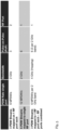
- the advantage can be achieved that the corresponding system is scalable in different ways. It is noted that for the sake of better comprehensibility, the corresponding several mapping options in the context of PDW streaming are summarized in Fig. 5 on the basis of corresponding numerical examples.
- the system such as the system 20, 40, 60, 80, can especially be seen as a system with scalable number of radio frequency outputs and/or scalable pulse rate or pulse-on-pulse density and/or adaptive hopping bandwidth and/or intelligent pulse distribution.
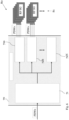
- Fig. 4 shows a further exemplary embodiment 50 of the inventive simulating device in combination with a further exemplary embodiment 60 of the inventive system.
- the device 50 is exemplarily connected to four radio frequency signal generators 61a, 61b, 61c, 61d, each of which especially comprises two port, preferably radio frequency outputs.
- each connection between the device 50 and the radio frequency signal generators 61a, 61b, 61c, 61d can comprise up to six PDW streams. Accordingly, each connection between the device 50 and the radio frequency signal generators 61a, 61b, 61c, 61d can have up to 12 MPDW/s in total.
- three PDW streams, 2 MPDW/s per stream, are exemplarily mapped to a first port or radio frequency output, respectively, of the first radio frequency signal generator 61a especially with a 2 GHz bandwidth.
- FIG. 6 a further exemplary embodiment 70 of the inventive simulating device in combination with a further exemplary embodiment 80 of the inventive system is illustrated.
- Said device 70 comprises a source signal terminal or an input server unit 71, respectively, exemplarily for receiving at least one PDW stream and N output server units 72a, 72b, ..., 72N exemplarily connected to the source signal terminal or the input server unit 71, respectively. Furthermore, at least a part, exemplarily two, preferably each, of the output server units 72a, 72b, ..., 72N is exemplarily configured for providing at least one PDW stream to a plurality 81 of radio frequency signal generators. In particular, it is noted that it might be advantageous if there is one output server unit per four radio frequency signal generators. Exemplarily, each of the first and the second output server units 72a, 72b are connected to four radio frequency signal generators of the plurality 81 of radio frequency signal generators. Further exemplarily, each of said radio frequency signal generators receives a corresponding PDW stream.
- one output server unit is responsible for one radio frequency output and thus streams only to the corresponding radio frequency signal generator.
- an output server unit can stream to multiple radio frequency signal generators.
- an output server unit can stream to multiple radio frequency signal generators.
- two radio frequency signal generators with six baseband boards each can be taken, and a combiner can be used to combine the corresponding signals.
Landscapes
- Engineering & Computer Science (AREA)
- Physics & Mathematics (AREA)
- Computer Networks & Wireless Communication (AREA)
- Electromagnetism (AREA)
- Signal Processing (AREA)
- General Physics & Mathematics (AREA)
- Radar, Positioning & Navigation (AREA)
- Remote Sensing (AREA)
- Spectroscopy & Molecular Physics (AREA)
- Mobile Radio Communication Systems (AREA)
Abstract
Description
- The invention relates to a simulating device for multiple parallel antenna signals, a system comprising such a device and a plurality of radio frequency signal generators, and a method for simulating multiple antenna signals in parallel.
- Generally, in times of an increasing number of application employing radar systems such as advanced driver assistance system or autonomous vehicles, there is a growing need of a simulating device for multiple parallel antenna signals, a system comprising such a device and a plurality of radio frequency signal generators, and a method for simulating multiple antenna signals in parallel for performing measurements with respect to such applications in order to verify their correct functioning.
-
US 2022/0179044 A1 relates to an apparatus for generating an emulated radar reflection signal of a target moving at a relative velocity. The apparatus includes a radar detector, an emulation transmitter, and a processor. The radar detector is configured to detect radar chirps emitted by a device under test (DUT), where the chirps are emitted at random time intervals. The emulation transmitter is configured to generate emulated radar reflection signals of the target being emulated. The processor is configured to generate control signals at intervals corresponding to the random time intervals at which the radar chirps are emitted by the DUT, where each control signal controls the emulation transmitter to generate a radar reflection signal. A relative phase of the control signals is adjusted according to a duration of each of the random time intervals between successive chirps and a magnitude and sign of the relative velocity of the target. Disadvantageously, especially due to the structure or the configuration, respectively, of said apparatus, a user cannot tailor said apparatus to the desired simulation requirements in a flexible and efficient manner. - Accordingly, there is the object to provide a simulating device for multiple parallel antenna signals, a system comprising such a device and a plurality of radio frequency signal generators, and a method for simulating multiple antenna signals in parallel, thereby allowing for adapting and tailoring the solution offered to the users based on their individual simulation needs in a highly flexible and particularly efficient manner.
- This object is solved by the features of the first independent claim for a simulating device for multiple parallel antenna signals, the features of the second independent claim for a system comprising such a device and a plurality of radio frequency signal generators, and the features of the third independent claim for a method for simulating multiple antenna signals in parallel. The dependent claims contain further developments.
- According to a first aspect of the invention, a simulating device for multiple parallel antenna signals is provided. Said device comprises at least one source signal terminal, an output processing stage for processing in parallel the at least one source signal with multiple parameters, each specific for one antenna of the multiple antennas, thus producing multiple antenna-specific output signals, and a plurality of output terminals, each of which being supplied with one of the multiple antenna-specific output signals, for supplying a plurality of radio frequency signal generators generating a plurality of simulated radio frequency signals.
- Advantageously, simulation can be adapted and/or tailored to desired simulation requirements in a highly flexible and particularly efficient manner.
- Further advantageously, the device can allow for a scalable number of radio frequency outputs and/or a scalable pulse rate and/or a scalable pulse-on-pulse density and/or an adaptive hopping bandwidth and/or an intelligent pulse distribution.
- According to a first implementation form of the first aspect of the invention, the device further comprises an input processing stage converting the data in the signal received from the at least one source signal terminal and distributing it to the output processing stage. Advantageously, for instance, the corresponding input signal can be translated.
- According to a second implementation form of the first aspect of the invention, the output processing stage comprises a plurality of parallel server units, one server unit per radio frequency signal generator or one server unit per several radio frequency signal generators. Advantageously, for example, the server units and/or the input processing stage can abstract the radio frequency signal generators according to their functionality and split the corresponding input signal in such a way that a complex signal and/or scenario can be represented especially at the output or outputs, respectively, of the radio frequency signal generators.
- According to a further implementation form of the first aspect of the invention, the simulated radio frequency signals are radar pulses and/or navigation signals. Advantageously, for instance, flexibility can further be increased.
- According to a further implementation form of the first aspect of the invention, the parameters include at least one of antenna characteristics and/or antenna location. Advantageously, for example, inefficiencies can further be reduced.
- According to a further implementation form of the first aspect of the invention, the at least one source signal terminal is configured to receive specific data from at least one database or databases, exemplarily for radar signals. In this context, the at least one source signal terminal is especially configured to form the at least one source signal on the basis of the specific data. Advantageously, for instance, efficiency can further be increased.
- According to a further implementation form of the first aspect of the invention, the at least one source signal terminal comprises information which radio frequency signal generator has which abilities. Advantageously, for example, said information can efficiently be gathered with the aid of the output processing stage especially from the radio frequency signal generators. Further advantageously, said information can be manually configured or requested by the parallel server units of the output processing stage from the radio frequency signal generators.
- According to a further implementation form of the first aspect of the invention, the input processing stage is configured to perform at least one port agnostic calculation, especially at least one output terminal agnostic calculation. Advantageously, for instance, not only flexibility but also efficiency can further be increased.
- According to a further implementation form of the first aspect of the invention, the at least one port agnostic calculation, especially the at least one output terminal agnostic calculation, comprises at least one of receiver properties, receiver movement, receiver velocity, doppler shift, signal attenuation, or any combination thereof. Advantageously, for example, inefficiencies can further be reduced. Further advantageously, it is also possible that an input signal to the source signal terminal or an input server, respectively, has the foregoing information already incorporated. In this case, the source signal terminal or the input server, respectively, does not need to do those particular calculations again but it can do it especially in the case that the input signal does not account for them.
- According to a second aspect of the invention, a multiple antenna signal generation system is provided. Said system comprises a simulation device according to the first aspect of the invention or any implementation form thereof, respectively, and a plurality of radio frequency signal generators connected to the output terminals of the simulating device, each radio frequency signal generator generating one or more output signals simulating antenna signals.
- Advantageously, simulation can be adapted and/or tailored to desired simulation requirements in a highly flexible and particularly efficient manner.
- Further advantageously, the system can allow for a scalable number of radio frequency outputs and/or a scalable pulse rate and/or a scalable pulse-on-pulse density and/or an adaptive hopping bandwidth and/or an intelligent pulse distribution.
- As a further advantage, the frequency range can also be flexible. For example, one radio frequency signal generator may simulate from 18 GHz to 20 GHz and another one from 28 GHz to 30 GHz. The source signal terminal or an input server, respectively, can intelligently assign the respective pulses to the corresponding output especially based on the corresponding simulation scenario.
- According to a first implementation form of the second aspect of the invention, an input stage, especially the input processing stage, of the simulating device distributes the converted data to the parallel server units of the output processing stage in a manner, exemplarily as to the bandwidth, taking into account characteristics of the radio frequency signal generator supplied by the respective server unit and/or the plurality of output terminals. Advantageously, for instance, said characteristics can efficiently be gathered with the aid of the output processing stage or the server units, respectively, especially from the respective radio frequency signal generator. Further advantageously, said characteristics can be manually configured or requested by the server units of the output processing stage from the radio frequency signal generators.
- According to a second implementation form of the second aspect of the invention, the one or more output signals represent a respective realistic antenna output and/or input signal. Advantageously, for example, efficiency can further be increased.
- According to a further implementation form of the second aspect of the invention, each radio frequency signal generator is configured to simulate a hopping range up to a certain bandwidth. Advantageously, for instance, a further radio frequency signal generator can be added via a combiner if a wider hopping bandwidth is desired, thereby increasing both flexibility and efficiency.
- According to a further implementation form of the second aspect of the invention, each radio frequency signal generator is configured with an interface to accommodate several base band units, especially several base band boards. Advantageously, for example, such a based band unit or base band board, respectively, can be configured to be coupled, especially detachably coupled, to the respective radio frequency signal generator or the corresponding interface thereof, respectively, which leads to an increased flexibility and efficiency.
- According to a third aspect of the invention, a method for simulating multiple antenna signals in parallel is provided. Said method comprises the steps of providing at least one source signal, converting the source signal, processing in parallel the at least one converted source signal with multiple parameters, each specific for one antenna of the multiple antennas, thus producing multiple antenna-specific output signals, and supplying the multiple antenna-specific output signals to a plurality of radio frequency signal generators generating a plurality of simulated radio frequency signals.
- Advantageously, simulation can be adapted and/or tailored to desired simulation requirements in a highly flexible and particularly efficient manner.
- Further advantageously, the method can allow for a scalable number of radio frequency outputs and/or a scalable pulse rate and/or a scalable pulse-on-pulse density and/or an adaptive hopping bandwidth and/or an intelligent pulse distribution.
- Exemplary embodiments of the invention are now further explained with respect to the drawings by way of example only, and not for limitation. In the drawings:
- Fig. 1
- shows an exemplary embodiment of a simulating device according to the first aspect of the invention in combination with an exemplary embodiment of a system according to the second aspect of the invention;
- Fig. 2
- shows a further exemplary embodiment of the inventive simulating device in combination with a further exemplary embodiment of the inventive system;
- Fig. 3
- shows an exemplary embodiment of a radio frequency signal generator in the context of the invention;
- Fig. 4
- shows a further exemplary embodiment of the inventive simulating device in combination with a further exemplary embodiment of the inventive system;
- Fig. 5
- shows several mapping options in the context of Pulse Descriptor Words (PDW) streaming in the sense of the invention;
- Fig. 6
- shows a further exemplary embodiment of the inventive simulating device in combination with a further exemplary embodiment of the inventive system; and
- Fig. 7
- shows a flow chart of an exemplary embodiment of the third aspect of the invention.
- With respect to
Fig. 1 , a block diagram of anexemplary embodiment 10 of a simulating device for multiple parallel antenna signals according to the first aspect of the invention in combination with anexemplary embodiment 20 of a system according to the second aspect of the invention is illustrated. - The simulating
device 10 comprises at least one source signal terminal, exemplarily thesource signal terminal 11, anoutput processing stage 12 for processing in parallel the at least one source signal with multiple parameters, each specific for one antenna of the multiple antennas, thus producing multiple antenna-specific output signals, and a plurality ofoutput terminals 13, each of which being supplied with one of the multiple antenna-specific output signals, for supplying a plurality of radio frequency signal generators, exemplarily the four radiofrequency signal generators - As it can further be seen from
Fig. 1 , it might be advantageous if thedevice 10 further comprises aninput processing stage 14 converting the data in the signal received from the at least onesource signal terminal 11 and distributing it to theoutput processing stage 12. - It is noted that it might be advantageous if the
output processing stage 12 comprises a plurality of parallel server units, one server unit per radio frequency signal generator or one server unit per several radio frequency signal generators. - It is further noted that the simulated radio frequency signals may preferably be radar pulses and/or navigation signals.
- Furthermore, it might be advantageous if the above-mentioned parameters include at least one of antenna characteristics and/or antenna location.
- With respect to the
source signal terminal 11, it is noted that it might be advantageous ifsource signal terminal 11 is configured to receive specific data from at least one database or databases, exemplarily for radar signals. In this context, thesource signal terminal 11 is especially configured to form the at least one source signal on the basis of the specific data. - It is noted that it might be advantageous if the
source signal terminal 11 comprises information which radio frequency signal generator has which abilities. - With respect to the
input processing stage 14, it is noted that it might be advantageous if theinput processing stage 14 is configured to perform at least one port agnostic calculation, especially at least one output terminal agnostic calculation. - In this context, the at least one port agnostic calculation, especially the at least one output terminal agnostic calculation, may preferably comprise at least one of receiver properties, receiver movement, receiver velocity, doppler shift, signal attenuation, or any combination thereof.
- It is noted that it is also possible that an input signal to the
source signal terminal 11 or theinput processing stage 14, respectively, has the foregoing information already incorporated. In this case, thesource signal terminal 11 or theinput processing stage 14, respectively, does not need to do those particular calculations again but it can do it especially in the case that the input signal does not account for them. - As already mentioned above,
Fig. 1 also depicts anexemplary embodiment 20 of the multiple antenna signal generation system. Saidsystem 20 comprises thesimulation device 10 and a plurality of radio frequency signal generators, exemplarily the four radiofrequency signal generators output terminals 13 of the simulatingdevice 10, each radiofrequency signal generator - Especially for the above-mentioned advantageous case that the
output processing stage 12 comprises a plurality of parallel server units, one server unit per radio frequency signal generator or one server unit per several radio frequency signal generators, it is noted that it might be advantageous if an input stage, exemplarily theinput processing stage 14, of the simulatingdevice 10 distributes the converted data to the parallel server units of theoutput stage 12 in a manner, exemplarily as to the bandwidth, taking into account characteristics of the radio frequency signal generator supplied by the respective server unit and/or the plurality ofoutput terminals 13. - It is further noted that it might be advantageous if the one or more output signals represent a respective realistic antenna output and/or input signal.
- Moreover, with respect to the radio
frequency signal generators - In addition to this or as an alternative, each radio frequency signal generator may preferably be configured with an interface to accommodate several base band units, especially several base band boards.
- For the sake of completeness, with respect to the corresponding interconnections between the elements or parts, respectively, of
Fig. 1 , it is noted that thesource signal terminal 11 is connected to theoutput processing stage 12 especially via theinput processing stage 14 if present. Furthermore, theoutput processing stage 12 is exemplarily connected to the plurality ofoutput terminals 13. Moreover, said plurality ofoutput terminals 13 is exemplarily connected to the plurality of radiofrequency signal generators - Now, with respect to
Fig. 2 , a furtherexemplary embodiment 30 of the inventive simulating device in combination with a further exemplary embodiment of theinventive system 40 is depicted. - Exemplarily, the
device 30 comprises aninput server unit 31. With respect to saidinput server unit 31, it is noted that the explanations regarding thesource signal terminal 11 above can additionally or alternatively apply for saidinput server unit 31, and vice versa. This can analogously apply forelement 71 ofFig. 6 , and vice versa. Furthermore, thesource signal terminal 11 may especially comprise or be theinput server unit 31 orelement 71, respectively. - Said
input server unit 31 is exemplarily configured for receiving input data and/or transforming and/or converting and/or reformatting data, especially said input data, into a new output format. - Especially in the context of converting said data, it might be advantageous if the corresponding data is converted from a custom and/or proprietary to any output format, or from any input format to any output format.
- Accordingly, the
system 40 can especially be seen as a signal generation system with input signal translation. - It is noted that it might be advantageous if the
input server unit 31 is configured for modifying the input data or an input signal according to corresponding simulation parameters. For example, said simulation parameters can comprise distance of the simulated radar receiver and/or corresponding position. - As it can further be seen from
Fig. 2 , thedevice 30 comprises aninput processing stage 34 exemplarily connected to theinput server unit 31. With respect to saidinput processing stage 34, it is noted that the explanations regarding theinput processing stage 14 above can additionally or alternatively apply for saidinput processing stage 34, and vice versa. Furthermore, theinput server unit 31 can especially comprise saidinput processing stage 34. - Said
input processing stage 34 or saidinput server unit 31, respectively, can especially be configured to arbitrate and/or schedule and/or route the respective signals according to the functionality and/or port mapping of the corresponding ones of the radio frequency signal generators, exemplarily the N radiofrequency signal generators - With respect to said radio
frequency signal generators frequency signal generators frequency signal generators element 61 ofFig. 3 ,elements Fig. 4 , and/orelement 81 ofFig. 6 , and vice versa. - Moreover, the
input processing stage 34 is exemplarily connected to a plurality of parallel server units, especially Noutput server units output server units Fig. 1 can additionally or alternatively apply for saidoutput server units elements Fig. 6 , and vice versa. - In addition or as an alternative to the
input processing stage 34 or theinput server unit 31, respectively, saidoutput server units frequency signal generators - In this context, it might be advantageous if the
input processing stage 34 or theinput server unit 31, respectively, and theoutput server units frequency signal generators - With respect to the
output server units frequency signal generators system 40 can be scaled appropriately depending on the use case. - Accordingly, the
system 40 can especially be seen as a signal generation system with a scalable number of radio frequency outputs. Especially in the light of the above-mentioned input signal translation, thesystem 40 may be seen as a signal generation system with input signal translation and a scalable number of radio frequency outputs. - It is further noted that it is also possible that each output server is connected to at least one signal generator.
- Moreover, it might be advantageous if there is an assignment of the respective pulses or PDW, respectively, to the corresponding output servers especially based on the attached or connected radio frequency signal generators.
- As it can further be seen from
Fig. 2 , thedevice 30 comprises plurality ofoutput terminals 33. With respect to said plurality ofoutput terminals 33, it is noted that the explanations regarding the plurality ofoutput terminals 13 can additionally or alternatively apply for said plurality ofoutput terminals 33, and vice versa. Furthermore, theoutput server units output terminals 33. - With respect to the radio
frequency signal generators - Accordingly, the corresponding communication of the
input processing stage 34 and/or the plurality ofoutput terminals 33 may preferably be based on a stream, especially a PDW stream. Additionally or alternatively, said communication may be based on Ethernet, especially 10 Gbit Ethernet. - With respect to the radio
frequency signal generators - Furthermore, each radio frequency signal generator can be configured with an interface to accommodate several base band units or base band boards, respectively. This advantageously enables a higher streaming bit rate or streaming PDW rate.
- Moreover, each radio frequency signal generator can be configured to simulate a hopping range up to an certain bandwidth, exemplarily up to 2 GHz or more, especially up to 4 GHz.
- It is noted that it might be advantageous if each radio frequency signal generator is configured to receive at least one data stream for generating at least one radio frequency output signal.
- Said radio frequency output signal may preferably represent a realistic antenna output signal, especially transmitter signal, and/or realistic antenna input signal, especially receiver signal. For instance, said radio frequency output signal can be an overlayed signal.
- Again, with respect to the
input server unit 31, it is noted that theinput server unit 31 may further be configured to receive specific data from at least one database or databases, exemplarily for radar signals. - It might be advantageous if the
input server unit 31 has the information which signal generator has which abilities. Advantageously, theinput server unit 31 may preferably perform channel assignment based on the frequency and/or power bands of the ports within the radiofrequency signal generators - Additionally or alternatively, the
input server unit 31 may be configured to perform any port agnostic calculations, exemplarily at least one of receiver properties, receiver movement, receiver velocity, doppler shift, signal attenuation, or any combination thereof. - In further addition to this or as a further alternative, the
input server unit 31 may be configured to distribute data, especially a PDW, to the respective radio frequency signal generator with the correct predefined frequency range. For example, one of the radiofrequency signal generators frequency signal generator 41a, may comprise a frequency range of 18 GHz to 20 GHz, whereas another one of the radiofrequency signal generators frequency signal generator 41b, may comprise a frequency range of 20 GHz to 22 GHz. - With respect to the
output server units output server units - As it can further be seen from
Fig. 2 , thesystem 40 exemplarily comprises a device under test or a system undertest 49, respectively. In this context, thesystem 40 is configured to generate radar signals of interest especially with respect to said device under test or said system undertest 49, respectively. - It is noted that it might be advantageous if the
system 40 comprises Mcombiners test 49, respectively. Accordingly, thesystem 40 may comprise a plurality of combiners, one for each port of the device under test or the system undertest 49, respectively. For instance, the device under test or the system undertest 49, respectively, may comprise 8 ports, whereas thesystem 40 may comprise 8 combiners, one for each of said 8 ports. - Advantageously, another radio frequency generator can be added via such a combiner if a wider hopping bandwidth is necessary or desired, respectively.
- Further advantageously, the scheduling which respective radio frequency pulse is simulated on which corresponding radio frequency port can especially be done by the
input server unit 31 and/or at least one, preferably each, of theoutput server units - It is further noted that it might be advantageous if the
device 30 is configured to perform transformation and/or scheduling and/or arbitration of input PDWs into a desired PDW format which is interpretable by the radiofrequency signal generators - Now, with respect to
Fig. 3 , anexemplary embodiment 61 of a radio frequency signal generator, such as thesignal generators - As already mentioned above, several base band units or base band boards, respectively, can be used for the radio
frequency signal generator 61. Exemplarily, the radio frequency signal generator comprises sixbase band units base band units base band boards frequency signal generator 61 or a corresponding interface thereof, respectively. - As it can further be seen from
Fig. 3 , the radiofrequency signal generator 61 comprises two ports, especially tworadio frequency outputs 63a, 63b. - With respect to the
base band boards base band boards - As exemplarily shown according to
Fig. 3 ,6 baseband boards have been accommodated for a total rate of 12 MPDW/s per radio frequency output. - Accordingly, especially in the context of the radio
frequency signal generators - Advantageously, for instance, adding another radio frequency signal generator could be used to double the number of radio frequency outputs especially with the same PDW rate.
- As an alternative, especially in the context of the above-mentioned
combiners - Yet another option is to add a radio frequency signal generator, combine the radio frequency outputs and stream PDW data to either first or second radio frequency signal generator, effectively resulting in doubling the maximum hopping bandwidth while not changing the effective PDW rate.
- Especially in the light of the foregoing three alternatives, for example, the advantage can be achieved that the corresponding system is scalable in different ways. It is noted that for the sake of better comprehensibility, the corresponding several mapping options in the context of PDW streaming are summarized in
Fig. 5 on the basis of corresponding numerical examples. - With respect to the scalability of the system in accordance with the invention, it is noted that the system, such as the
system - Especially following the numerical example regarding PDW stream mapping according to
Fig. 5 ,Fig. 4 shows a furtherexemplary embodiment 50 of the inventive simulating device in combination with a furtherexemplary embodiment 60 of the inventive system. - According to said
Fig. 4 , thedevice 50 is exemplarily connected to four radiofrequency signal generators - Furthermore, each connection between the
device 50 and the radiofrequency signal generators device 50 and the radiofrequency signal generators - Moreover, as it can further be seen from
Fig. 4 , three PDW streams, 2 MPDW/s per stream, are exemplarily mapped to a first port or radio frequency output, respectively, of the first radiofrequency signal generator 61a especially with a 2 GHz bandwidth. - Now, with respect to
Fig. 6 , a furtherexemplary embodiment 70 of the inventive simulating device in combination with a furtherexemplary embodiment 80 of the inventive system is illustrated. - Said
device 70 comprises a source signal terminal or aninput server unit 71, respectively, exemplarily for receiving at least one PDW stream and Noutput server units input server unit 71, respectively. Furthermore, at least a part, exemplarily two, preferably each, of theoutput server units plurality 81 of radio frequency signal generators. In particular, it is noted that it might be advantageous if there is one output server unit per four radio frequency signal generators. Exemplarily, each of the first and the secondoutput server units plurality 81 of radio frequency signal generators. Further exemplarily, each of said radio frequency signal generators receives a corresponding PDW stream. - It is noted that it might be advantageous if one output server unit is responsible for one radio frequency output and thus streams only to the corresponding radio frequency signal generator.
- It is further noted that it might be advantageous if especially for the case that multiple radio frequency signal generators form a single radio frequency output, then an output server unit can stream to multiple radio frequency signal generators. For the exemplary case that a user requires 24 MPDW/s, then two radio frequency signal generators with six baseband boards each can be taken, and a combiner can be used to combine the corresponding signals.
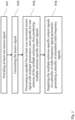
- Finally,
Fig. 7 shows a flow chart of an exemplary embodiment of the inventive method for simulating multiple antenna signals in parallel. Afirst step 101 comprises providing at least one source signal. Asecond step 102 comprises converting the source signal. Furthermore, athird step 103 comprises processing in parallel the at least one converted source signal with multiple parameters, each specific for one antenna of the multiple antennas, thus producing multiple antenna-specific output signals. In addition to this, a fourth step comprises supplying the multiple antenna-specific output signals to a plurality of radio frequency signal generators generating a plurality of simulated radio frequency signals. - While various embodiments of the present invention have been described above, it should be understood that they have been presented by way of example only, and not limitation. Numerous changes to the disclosed embodiments can be made in accordance with the disclosure herein without departing from the spirit or scope of the invention. Thus, the breadth and scope of the present invention should not be limited by any of the above described embodiments. Rather, the scope of the invention should be defined in accordance with the following claims and their equivalents.
- Although the invention has been illustrated and described with respect to one or more implementations, equivalent alterations and modifications will occur to others skilled in the art upon the reading and understanding of this specification and the annexed drawings. In addition, while a particular feature of the invention may have been disclosed with respect to only one of several implementations, such feature may be combined with one or more other features of the other implementations as may be desired and advantageous for any given or particular application.
Claims (15)
- Simulating device (10, 30, 50, 70) for multiple parallel antenna signals, the device (10, 30, 50, 70) comprising:- at least one source signal terminal (11, 31, 71),- an output processing stage (12) for processing in parallel the at least one source signal with multiple parameters, each specific for one antenna of the multiple antennas, thus producing multiple antenna-specific output signals, and- a plurality of output terminals (13, 33), each of which being supplied with one of the multiple antenna-specific output signals, for supplying a plurality of radio frequency signal generators (21a, 21b, 21c, 21d, 41a, 41b, ..., 41N, 61a, 61b, 61c, 61d, 81) generating a plurality of simulated radio frequency signals.
- The device (10, 30, 50, 70) of claim 1,
further comprising an input processing stage (14, 34) converting the data in the signal received from the at least one source signal terminal (11, 31, 71) and distributing it to the output processing stage (12). - The device (10, 30, 50, 70) of claim 1 or 2,
wherein the output processing stage (12) comprises a plurality of parallel server units (32a, 32b, ..., 32N, 72a, 72b, ..., 72N), one server unit (32a, 32b, ..., 32N) per radio frequency signal generator (21a, 21b, 21c, 21d, 41a, 41b, ..., 41N, 61a, 61b, 61c, 61d) or one server unit (72a, 72b, ..., 72N) per several radio frequency signal generators (81). - The device (10, 30, 50, 70) of any of the preceding claims,
wherein the simulated radio frequency signals are radar pulses and/or navigation signals. - The device (10, 30, 50, 70) of any of the preceding claims,
wherein the parameters include at least one of antenna characteristics and/or antenna location. - The device (10, 30, 50, 70) of any of the preceding claims,
wherein the at least one source signal terminal (11, 31, 71) is configured to receive specific data from at least one database or databases, exemplarily for radar signals, wherein the at least one source signal terminal (11, 31, 71) is especially configured to form the at least one source signal on the basis of the specific data. - The device (10, 30, 50, 70) of any of the preceding claims,
wherein the at least one source signal terminal (11, 31, 71) comprises information which radio frequency signal generator (21a, 21b, 21c, 21d, 41a, 41b, ..., 41N, 61a, 61b, 61c, 61d, 81) has which abilities. - The device (10, 30, 50, 70) of any of the claims 2 to 7,
wherein the input processing stage (14, 34) is configured to perform at least one port agnostic calculation, especially at least one output terminal agnostic calculation. - The device (10, 30, 50, 70) according to claim 8, wherein the at least one port agnostic calculation, especially the at least one output terminal agnostic calculation, comprises at least one of receiver properties, receiver movement, receiver velocity, doppler shift, signal attenuation, or any combination thereof.
- A multiple antenna signal generation system (20, 40, 60, 80), the system (20, 40, 60, 80) comprising a simulation device (10, 30, 50, 70) according to any of the preceding claims and a plurality of radio frequency signal generators (21a, 21b, 21c, 21d, 41a, 41b, ..., 41N, 61a, 61b, 61c, 61d, 81) connected to the output terminals (13, 33) of the simulating device (10, 30, 50, 70), each radio frequency signal generator (21a, 21b, 21c, 21d, 41a, 41b, ..., 41N, 61a, 61b, 61c, 61d, 81) generating one or more output signals simulating antenna signals.
- The system (20, 40, 60, 80) of claim 10,
wherein an input stage, especially the input processing stage (14, 34), of the simulating device (10, 30, 50, 70) distributes the converted data to the parallel server units (32a, 32b, ..., 32N, 72a, 72b, ..., 72N) of the output processing stage (12) in a manner, exemplarily as to the bandwidth, taking into account characteristics of the radio frequency signal generator (21a, 21b, 21c, 21d, 41a, 41b, ..., 41N, 61a, 61b, 61c, 61d, 81) supplied by the respective server unit (32a, 32b, ..., 32N, 72a, 72b, ..., 72N) and/or the plurality of output terminals (13, 33). - The system (20, 40, 60, 80) of claim 10 or 11,
wherein the one or more output signals represent a respective realistic antenna output and/or input signal. - The system (20, 40, 60, 80) of any of the claims 10 to 12,
wherein each radio frequency signal generator (21a, 21b, 21c, 21d, 41a, 41b, ..., 41N, 61a, 61b, 61c, 61d, 81) is configured to simulate a hopping range up to a certain bandwidth. - The system (20, 40, 60, 80) of any of the claims 10 to 13,
wherein each radio frequency signal generator (21a, 21b, 21c, 21d, 41a, 41b, ..., 41N, 61a, 61b, 61c, 61d, 81) is configured with an interface to accommodate several base band units (64a, 64b, 64c, 64d, 64e, 64f), especially several base band boards. - A method for simulating multiple antenna signals in parallel, the method comprising the steps of:- providing (101) at least one source signal,- converting (102) the source signal,- processing (103) in parallel the at least one converted source signal with multiple parameters, each specific for one antenna of the multiple antennas, thus producing multiple antenna-specific output signals, and- supplying (104) the multiple antenna-specific output signals to a plurality of radio frequency signal generators generating a plurality of simulated radio frequency signals.
Priority Applications (2)
| Application Number | Priority Date | Filing Date | Title |
|---|---|---|---|
| EP23164870.0A EP4439113A1 (en) | 2023-03-29 | 2023-03-29 | Simulating device for multiple parallel antenna signals, corresponding system and method |
| US18/407,091 US20240333402A1 (en) | 2023-03-29 | 2024-01-08 | Simulating device for multiple parallel antenna signals, corresponding system and method |
Applications Claiming Priority (1)
| Application Number | Priority Date | Filing Date | Title |
|---|---|---|---|
| EP23164870.0A EP4439113A1 (en) | 2023-03-29 | 2023-03-29 | Simulating device for multiple parallel antenna signals, corresponding system and method |
Publications (1)
| Publication Number | Publication Date |
|---|---|
| EP4439113A1 true EP4439113A1 (en) | 2024-10-02 |
Family
ID=85781611
Family Applications (1)
| Application Number | Title | Priority Date | Filing Date |
|---|---|---|---|
| EP23164870.0A Pending EP4439113A1 (en) | 2023-03-29 | 2023-03-29 | Simulating device for multiple parallel antenna signals, corresponding system and method |
Country Status (2)
| Country | Link |
|---|---|
| US (1) | US20240333402A1 (en) |
| EP (1) | EP4439113A1 (en) |
Citations (2)
| Publication number | Priority date | Publication date | Assignee | Title |
|---|---|---|---|---|
| US10571551B2 (en) * | 2016-05-05 | 2020-02-25 | Rohde & Schwarz Gmbh & Co. Kg | Signal generation device and method |
| US20220179044A1 (en) | 2020-12-07 | 2022-06-09 | Keysight Technologies, Inc. | Frequency modulated continuous wave (fmcw) radar target emulation with synchronized modulation reflection devices |
-
2023
- 2023-03-29 EP EP23164870.0A patent/EP4439113A1/en active Pending
-
2024
- 2024-01-08 US US18/407,091 patent/US20240333402A1/en active Pending
Patent Citations (2)
| Publication number | Priority date | Publication date | Assignee | Title |
|---|---|---|---|---|
| US10571551B2 (en) * | 2016-05-05 | 2020-02-25 | Rohde & Schwarz Gmbh & Co. Kg | Signal generation device and method |
| US20220179044A1 (en) | 2020-12-07 | 2022-06-09 | Keysight Technologies, Inc. | Frequency modulated continuous wave (fmcw) radar target emulation with synchronized modulation reflection devices |
Non-Patent Citations (1)
| Title |
|---|
| ANONYMOUS: "Pulse Sequencer Pulse Signal Generation Software (Version 09)", USER MANUAL, 1 January 2018 (2018-01-01), München, DE, pages 1 - 758, XP055726422, Retrieved from the Internet <URL:https://scdn.rohde-schwarz.com/ur/pws/dl_downloads/dl_common_library/dl_manuals/gb_1/s/smx/k300_k3001/RS_PulseSequencer_UserManual_en_09.pdf> * |
Also Published As
| Publication number | Publication date |
|---|---|
| US20240333402A1 (en) | 2024-10-03 |
Similar Documents
| Publication | Publication Date | Title |
|---|---|---|
| CN113805205B (en) | True satellite signal simulation device, method, equipment and medium based on starry sky | |
| CN108012574B (en) | Wireless power transfer system, method of operating the same, and apparatus therefor | |
| CN106483512A (en) | A kind of general multichannel distributed object analogue echoes method and if system | |
| GB2536539A (en) | System and method for testing multi-user, multi-input/multi-output systems | |
| EP4387129A1 (en) | Distributed and scalable system for emulating radio frequency channels | |
| CN110291412A (en) | Radar target simulator with overlay device and method for overlaying signals | |
| CN107085385A (en) | A kind of analogue system and method for simulating multi-aircraft autonomous flight | |
| JP4046609B2 (en) | Method and apparatus for simulating a radio channel | |
| CN115276764B (en) | Comprehensive simulation system, method and storage medium of low-orbit satellite access network system | |
| EP1186124A2 (en) | Apparatus for testing mobile phones | |
| JP5052379B2 (en) | Radar target simulator device | |
| US20240333402A1 (en) | Simulating device for multiple parallel antenna signals, corresponding system and method | |
| CN103795480A (en) | Multi-channel networking test device of directional communication system | |
| CN120294695A (en) | A system and method for simulating electronic targets for multi-mode broadband radar onboard unmanned aerial vehicles | |
| EP3862790A1 (en) | Signal generation system as well as method of signal generation | |
| US20250231281A1 (en) | Radar target simulator, corresponding antenna array and radar target simulation method | |
| US20210063528A1 (en) | Radar sensor system and method for producing a radar sensor system | |
| US8711962B2 (en) | Method for generating multi-antenna signals | |
| CN117518104A (en) | Realizing a broadband radio frequency array cluster target simulation system based on D-F-D architecture | |
| CN209642983U (en) | A kind of greenhouse sensor positioning system | |
| CN105227254B (en) | A kind of novel multi-channel meteor trail channel simulator | |
| CN119174216A (en) | Integrated and compact intelligent transmitting and receiving system | |
| CN110716173B (en) | Measuring device and measuring method for determining a test signal for simulating a departure angle | |
| KR102316191B1 (en) | Apparatus and method for simulating monopulse signal | |
| CN118972306B (en) | A communication target system |
Legal Events
| Date | Code | Title | Description |
|---|---|---|---|
| PUAI | Public reference made under article 153(3) epc to a published international application that has entered the european phase |
Free format text: ORIGINAL CODE: 0009012 |
|
| STAA | Information on the status of an ep patent application or granted ep patent |
Free format text: STATUS: THE APPLICATION HAS BEEN PUBLISHED |
|
| STAA | Information on the status of an ep patent application or granted ep patent |
Free format text: STATUS: REQUEST FOR EXAMINATION WAS MADE |
|
| AK | Designated contracting states |
Kind code of ref document: A1 Designated state(s): AL AT BE BG CH CY CZ DE DK EE ES FI FR GB GR HR HU IE IS IT LI LT LU LV MC ME MK MT NL NO PL PT RO RS SE SI SK SM TR |
|
| 17P | Request for examination filed |
Effective date: 20240911 |
|
| RBV | Designated contracting states (corrected) |
Designated state(s): AL AT BE BG CH CY CZ DE DK EE ES FI FR GB GR HR HU IE IS IT LI LT LU LV MC ME MK MT NL NO PL PT RO RS SE SI SK SM TR |