EP4439038A1 - Gas turbine vane body with instrumentation - Google Patents
Gas turbine vane body with instrumentation Download PDFInfo
- Publication number
- EP4439038A1 EP4439038A1 EP24160229.1A EP24160229A EP4439038A1 EP 4439038 A1 EP4439038 A1 EP 4439038A1 EP 24160229 A EP24160229 A EP 24160229A EP 4439038 A1 EP4439038 A1 EP 4439038A1
- Authority
- EP
- European Patent Office
- Prior art keywords
- wall
- vane body
- pressure side
- sensor
- suction side
- Prior art date
- Legal status (The legal status is an assumption and is not a legal conclusion. Google has not performed a legal analysis and makes no representation as to the accuracy of the status listed.)
- Pending
Links
- 238000004891 communication Methods 0.000 claims abstract description 34
- 239000012530 fluid Substances 0.000 claims abstract description 28
- 238000001816 cooling Methods 0.000 claims description 48
- 238000000034 method Methods 0.000 description 21
- 239000000523 sample Substances 0.000 description 19
- 238000004519 manufacturing process Methods 0.000 description 8
- 238000012360 testing method Methods 0.000 description 5
- 239000000463 material Substances 0.000 description 4
- 239000000654 additive Substances 0.000 description 3
- 230000000996 additive effect Effects 0.000 description 3
- PNEYBMLMFCGWSK-UHFFFAOYSA-N aluminium oxide Inorganic materials [O-2].[O-2].[O-2].[Al+3].[Al+3] PNEYBMLMFCGWSK-UHFFFAOYSA-N 0.000 description 2
- 238000005266 casting Methods 0.000 description 2
- 238000002485 combustion reaction Methods 0.000 description 2
- 238000010586 diagram Methods 0.000 description 2
- 230000000670 limiting effect Effects 0.000 description 2
- 230000003068 static effect Effects 0.000 description 2
- 238000012546 transfer Methods 0.000 description 2
- 230000001154 acute effect Effects 0.000 description 1
- 229910045601 alloy Inorganic materials 0.000 description 1
- 239000000956 alloy Substances 0.000 description 1
- 238000013459 approach Methods 0.000 description 1
- 230000004888 barrier function Effects 0.000 description 1
- 230000007423 decrease Effects 0.000 description 1
- 230000003247 decreasing effect Effects 0.000 description 1
- 230000000694 effects Effects 0.000 description 1
- 230000007613 environmental effect Effects 0.000 description 1
- 239000000446 fuel Substances 0.000 description 1
- 229910000856 hastalloy Inorganic materials 0.000 description 1
- 238000010438 heat treatment Methods 0.000 description 1
- 229910001119 inconels 625 Inorganic materials 0.000 description 1
- 229910000816 inconels 718 Inorganic materials 0.000 description 1
- 238000003754 machining Methods 0.000 description 1
- 238000005259 measurement Methods 0.000 description 1
- 229910052751 metal Inorganic materials 0.000 description 1
- 239000002184 metal Substances 0.000 description 1
- 239000000203 mixture Substances 0.000 description 1
- 230000036961 partial effect Effects 0.000 description 1
- BASFCYQUMIYNBI-UHFFFAOYSA-N platinum Chemical compound [Pt] BASFCYQUMIYNBI-UHFFFAOYSA-N 0.000 description 1
- 230000001681 protective effect Effects 0.000 description 1
- WFKWXMTUELFFGS-UHFFFAOYSA-N tungsten Chemical compound [W] WFKWXMTUELFFGS-UHFFFAOYSA-N 0.000 description 1
- 229910052721 tungsten Inorganic materials 0.000 description 1
- 239000010937 tungsten Substances 0.000 description 1
- 238000011144 upstream manufacturing Methods 0.000 description 1
- 238000013022 venting Methods 0.000 description 1
- 238000003466 welding Methods 0.000 description 1
Images




Classifications
-
- G—PHYSICS
- G01—MEASURING; TESTING
- G01M—TESTING STATIC OR DYNAMIC BALANCE OF MACHINES OR STRUCTURES; TESTING OF STRUCTURES OR APPARATUS, NOT OTHERWISE PROVIDED FOR
- G01M15/00—Testing of engines
- G01M15/14—Testing gas-turbine engines or jet-propulsion engines
-
- F—MECHANICAL ENGINEERING; LIGHTING; HEATING; WEAPONS; BLASTING
- F01—MACHINES OR ENGINES IN GENERAL; ENGINE PLANTS IN GENERAL; STEAM ENGINES
- F01D—NON-POSITIVE DISPLACEMENT MACHINES OR ENGINES, e.g. STEAM TURBINES
- F01D17/00—Regulating or controlling by varying flow
- F01D17/02—Arrangement of sensing elements
- F01D17/08—Arrangement of sensing elements responsive to condition of working-fluid, e.g. pressure
- F01D17/085—Arrangement of sensing elements responsive to condition of working-fluid, e.g. pressure to temperature
-
- F—MECHANICAL ENGINEERING; LIGHTING; HEATING; WEAPONS; BLASTING
- F01—MACHINES OR ENGINES IN GENERAL; ENGINE PLANTS IN GENERAL; STEAM ENGINES
- F01D—NON-POSITIVE DISPLACEMENT MACHINES OR ENGINES, e.g. STEAM TURBINES
- F01D21/00—Shutting-down of machines or engines, e.g. in emergency; Regulating, controlling, or safety means not otherwise provided for
- F01D21/003—Arrangements for testing or measuring
-
- F—MECHANICAL ENGINEERING; LIGHTING; HEATING; WEAPONS; BLASTING
- F01—MACHINES OR ENGINES IN GENERAL; ENGINE PLANTS IN GENERAL; STEAM ENGINES
- F01D—NON-POSITIVE DISPLACEMENT MACHINES OR ENGINES, e.g. STEAM TURBINES
- F01D9/00—Stators
- F01D9/02—Nozzles; Nozzle boxes; Stator blades; Guide conduits, e.g. individual nozzles
- F01D9/04—Nozzles; Nozzle boxes; Stator blades; Guide conduits, e.g. individual nozzles forming ring or sector
- F01D9/041—Nozzles; Nozzle boxes; Stator blades; Guide conduits, e.g. individual nozzles forming ring or sector using blades
-
- F—MECHANICAL ENGINEERING; LIGHTING; HEATING; WEAPONS; BLASTING
- F05—INDEXING SCHEMES RELATING TO ENGINES OR PUMPS IN VARIOUS SUBCLASSES OF CLASSES F01-F04
- F05D—INDEXING SCHEME FOR ASPECTS RELATING TO NON-POSITIVE-DISPLACEMENT MACHINES OR ENGINES, GAS-TURBINES OR JET-PROPULSION PLANTS
- F05D2240/00—Components
- F05D2240/10—Stators
- F05D2240/12—Fluid guiding means, e.g. vanes
Definitions
- the present disclosure relates gas turbine engines in general and to sensing instrumentation for use with gas turbine engines in particular.
- core gas means gas that is ingested into the gas turbine engine and worked within the engine.
- the path that the core gas travels through the engine includes the passage through the compressor sections, the combustor, and the turbine sections.
- the "core gas” may comprise only air (e.g., in the compressor sections) or it may include air and combustion products (e.g., in the turbine sections).
- the core gas environment requires core gas sensors be made of materials that can withstand very high temperatures. In some instances, core gas sensors are configured with a cooling capability to enhance their ability to withstand the high temperature environment. Core gas parameters including temperature, pressure, and gas species are sensed to evaluate the performance of the gas turbine engine.
- test rig it is known to use a "test rig" to sense core gas parameters within a gas turbine engine.
- a test rig may be a gas turbine engine that is specially configured with sensors and sensor probes to collect core gas parameter data.
- a Kiel probe is an example of a sensor probe that can be used to sense stagnation pressure and temperature of the core gas flow.
- a Kiel probe typically includes a temperature or pressure measuring device disposed within the open cavity of a shroud body or shielded body. The shroud body and measuring device may be disposed at the end of a stem structure that extends into the core gas path and dictates the radial position of the Kiel probe head within the core gas path.
- Some Kiel probe embodiments include a stem having a plurality of probe heads (i.e., probe heads in one or more rows), each disposed at a different radial position when installed. These type of probe embodiments permit sensing at different radial positions without the need to adjust or use different length probe stems.
- Core gas parameter probes like a Kiel probe are not without issues. As stated above, the need to withstand high temperatures can limit the material used to construct such probes, and in some instances may require cooling. In addition to the temperature limitations, it is not always possible to position Kiel probes in optimum positions within the core gas path. Even if it is possible to position the probes in a desirable location, the probes are foreign to the core gas path (i.e., they would not normally be in the core gas path in a gas turbine engine) and create undesirable flow obstructions in the core gas path.
- What is needed is a structure capable of collecting core gas parameters that can withstand the environmental temperatures, and one that does not create a flow obstruction within the core gas flow path.
- an instrumented vane body includes a suction side outer wall, a suction side inner wall, a pressure side outer wall, a pressure suction side inner wall, at least one supply conduit, a plurality of sensor ports, a plurality of sensors, an egress conduit, and a plurality of trailing edge vents.
- the suction side outer and inner walls extend chordwise between a leading edge and a trailing edge and between an inner radial end and an outer radial end.
- the suction side outer and inner walls are spaced apart from one another forming a suction side passage therebetween.
- the pressure side outer and inner walls both extend chordwise between the leading edge and the trailing edge and between then inner radial end and the outer radial end.
- the pressure side outer and inner walls are spaced apart from one another forming a pressure side passage therebetween.
- the suction and pressure side inner walls define an interior cavity.
- the at least one supply conduit is in fluid communication with the interior cavity through at least one of the inner radial end or the outer radial end.
- the suction side inner wall is configured to permit passage of cooling air from the interior cavity into the suction side passage, and the pressure side inner wall is configured to permit passage of cooling air from the interior cavity into the pressure side passage.
- the suction and pressure side passages are in fluid communication with an exterior of the vane body.
- the sensor ports are disposed in the leading edge, spaced apart from one another between the inner radial end and the outer radial end. Each sensor is disposed within a respective sensor port.
- the egress conduit extends within the interior cavity and out of the vane body at the inner or outer radial end, or both.
- the egress conduit is in fluid communication with the sensor ports.
- the trailing edge vents extend between the egress conduit and the exterior of the vane body proximate the trailing edge. The trailing edge vents are configured to provide fluid communication between the egress conduit and the exterior of the vane body.
- each sensor port may have an open end disposed in the leading edge.
- each sensor may have a forward end, and the forward end of the sensor is recessed within the respective sensor port.
- a sensor may be a thermocouple.
- the instrumented vane body may include a plurality of passages, where each respective passage extends between a respective sensor port and the egress conduit, providing fluid communication therebetween.
- the instrumented vane body may include a plurality of first support members extending between the suction side outer and inner walls, and a plurality of second support members extending between the pressure side outer and inner walls.
- suction side inner wall may include a plurality of suction side inner wall apertures extending through the suction side inner wall
- pressure side inner wall may include a plurality of pressure side inner wall apertures extending through the pressure side inner wall
- the suction side outer wall may include a plurality of suction side outer wall apertures extending through the suction side outer wall, or the pressure side outer wall may include a plurality of pressure side outer wall apertures extending through the pressure side outer wall, or both.
- the egress conduit may be sealed airtight to prevent core gas passage out of the egress conduit at the inner radial end, the outer radial end, or both.
- an instrumented vane body that includes a suction side outer wall, a pressure side outer wall, an interior cavity, at least one supply conduit, a plurality of sensors, and a plurality of sensor ports.
- the suction side and pressure side outer walls both extend chordwise between a leading edge and a trailing edge and between an inner radial end and an outer radial end.
- the at least one supply conduit is in fluid communication with the interior cavity.
- the at least one supply conduit is in communication with the interior cavity through at least one of the inner radial end or the outer radial end.
- the sensor ports are disposed in the leading edge. Each sensor port is configured to receive a sensor.
- the sensor ports are spaced apart from one another between the inner and outer radial ends.
- Each sensor port is in fluid communication with at least one vent aperture disposed proximate the trailing edge.
- Each sensor port is configured to permit core gas to enter that sensor part and exit the vane body through the at least one vent aperture.
- each sensor port may have an open end disposed in the leading edge.
- each sensor may be a thermocouple having a forward end.
- the forward end of each sensor is recessed within the respective sensor port a first distance.
- each sensor port may be an aperture that extends into the vane body substantially perpendicular to the leading edge.
- Each sensor port has an open end disposed in the leading edge and an inner diameter surface.
- the instrumented vane body may further include a plurality spacing cylinders, each spacing cylinder disposed in a respective sensor port and each spacing cylinder having a length that extends between a forward end and an aft end, and a center bore that extends lengthwise between the forward end and the aft end and has a center bore inner diameter surface.
- a portion of each respective sensor may be disposed within the center bore of a respective spacing cylinder.
- each spacing cylinder may be recessed within the respective sensor port a second distance, wherein the second distance is greater than the first distance.
- each respective spacing cylinder and each respective sensor disposed within that center bore may be configured such that an annular region is disposed between the center bore inner diameter surface and the respective sensor to permit gas passage through the annular region.
- the instrumented vane body may include an egress conduit and a plurality of passages.
- the egress conduit may extend within the interior cavity and out of the vane body at the inner or outer radial end.
- Each passage may extend between a respective sensor port and the egress conduit to provide fluid communication therebetween.
- the egress conduit may be in fluid communication with the at least one vent aperture disposed proximate the trailing edge.
- the instrumented vane body may include a plurality of sensing port vent passages disposed around the periphery of each sensor port, wherein each vent passage breaks through the sensor port inner diameter surface and extends into the vane body beyond the spacing cylinder aft end.
- the instrumented vane body may include a suction side inner wall extending chordwise between the leading edge and the trailing edge and between the inner radial end and the outer radial end, and spaced apart from the suction side outer wall to form a suction side passage therebetween, and a pressure side inner wall extending chordwise between the leading edge and the trailing edge and between the inner radial end and the outer radial end, and spaced apart from the pressure side outer wall to form a pressure side passage therebetween.
- the suction and pressure side passages may be in fluid communication with the interior cavity.
- the suction and pressure side passages may be in fluid communication with an exterior of the vane body.
- the instrumented vane body may include a plurality of first support members extending between the suction side outer and inner walls, and a plurality of second support members extending between the pressure side outer and inner walls.
- a stator vane assembly includes a plurality of stator vanes including at least one instrumented vane body.
- the instrumented vane body includes a suction side outer wall, a pressure side outer wall, an interior cavity, at least one supply conduit, a plurality of sensors, and a plurality of sensor ports.
- the suction side and pressure side outer walls extend chordwise between a leading edge and a trailing edge and between an inner radial end and an outer radial end.
- the at least one supply conduit is in fluid communication with the interior cavity through at least one of the inner radial end or the outer radial end.
- the sensor ports are disposed in the leading edge.
- Each respective sensor port is configured to receive a respective sensor, and the sensor ports are spaced apart from one another between the inner radial end and the outer radial end.
- Each sensor port is in fluid communication with at least one vent aperture disposed proximate the trailing edge.
- Each sensor port is configured to permit core gas to enter that sensor part and exit the vane body through the at least one vent aperture.
- the present disclosure is directed to an instrumentation body configured as a vane body that can be implemented in a gas turbine engine as a vane within a vane stator stage.
- FIG. 1 shows a partially sectioned diagrammatic view of a geared gas turbine engine 20.
- the gas turbine engine 20 extends along an axial centerline 22 between an upstream airflow inlet 24 and a downstream airflow exhaust 26.
- the gas turbine engine 20 includes a fan section 28, a compressor section 30, a combustor section 32, and a turbine section 34.
- the compressor section includes a low pressure compressor (LPC) 36 and a high pressure compressor (HPC) 38.
- the turbine section 34 includes a high pressure turbine (HPT) 40 and a low pressure turbine (LPT) 42.
- the engine sections are arranged sequentially along the centerline 22 within an engine housing.
- the fan section 28 is connected to a geared architecture 44, for example, through a fan shaft 46.
- the geared architecture 44 and the LPC 36 are connected to and driven by the LPT 42 through a low speed shaft 48.
- the HPC 38 is connected to and driven by the HPT 40 through a high speed shaft 50.
- the engine 20 also includes a stator vane assembly 52 located axially between the HPT 40 and the LPT 42.
- the stator vane assembly 52 is connected to a static case such that aerodynamic loads on the stator vane assembly 52 transfer to the static case.
- FIG. 2 diagrammatically illustrates a stator vane assembly 52 embodiment.
- the stator vane assembly 52 includes a plurality of distinct vane segments 54.
- Each of the vane segments 54 includes an inner radial platform 56, an outer radial platform 58, and at least one vane airfoil 60 connected at opposite ends thereof to the inner and outer radial platforms 56, 58. In other examples, there could be more than one airfoil 60 connected to the platforms 56, 58.
- the air within the core gas path may be referred to as "core air”.
- the air within the bypass gas path may be referred to as "bypass air”.
- the core air is directed through the engine sections 30, 32, 34 and exits the gas turbine engine 20 through the airflow exhaust 26 to provide forward engine thrust.
- fuel is injected into a combustion chamber and mixed with compressed core air. This fuel-core air mixture is ignited to power the gas turbine engine 20.
- the bypass air is directed through the bypass gas path and out of the gas turbine engine 20 through a bypass nozzle to provide additional forward engine thrust.
- an instrumented vane body 62 that can be implemented in a gas turbine engine 20 as a vane within turbine stator vane assembly 52 like that shown in FIG. 2 .
- One or more of the instrumented vane bodies 62 may be disposed within stator vane assembly 52 of a production gas turbine engine or within a gas turbine engine test rig.
- the present disclosure is not limited to a turbine stator vane application, and may alternatively or additionally be disposed as a stator vane deployed elsewhere in a gas turbine engine; e.g., in the compressor section.
- the present disclosure is also not limited to any particular stator vane assembly configuration.
- FIG. 3 an instrumented vane body 62 embodiment is diagrammatically shown.
- the instrumented vane body 62 may have an exterior shape the same as other vane airfoils disposed within a stator vane assembly.
- the example shown in FIG. 3 has an airfoil configuration with a leading edge 64, a trailing edge 66, an outer radial end 68, and inner radial end 70, a suction side 72, and a pressure side 74.
- the suction and pressure sides 72, 74 extend chordwise between the leading edge 64 and the trailing edge 66 and the inner and outer radial ends 70, 68.
- FIG. 4 illustrates a planar end view
- FIG. 5 illustrates a planar pressure side view
- FIG. 6 illustrates a planar suction side view
- FIG. 7 illustrates a planar leading edge view
- FIG. 8 illustrates a planar trailing edge view of the instrumented vane body 62 embodiment shown in FIG. 3 .
- the instrumented vane body 62 has a double wall configuration with a suction side outer wall 76, a suction side inner wall 78, a pressure side outer wall 80, and a pressure side inner wall 82.
- the suction side inner and outer walls 78, 76 are spaced apart from one another creating a suction side passage 84 therebetween.
- a plurality of support members 86 e.g., cylindrical pins
- the pressure side inner and outer walls 82, 80 are spaced apart from one another creating a pressure side passage 88 therebetween, and a plurality of support members 86 (e.g., cylindrical pins) extend within the pressure side passage 88 between and are attached to the facing surfaces of the pressure side inner and outer walls 82, 80.
- the suction side and pressure side inner walls 78, 82 define an interior cavity 90.
- the suction side and pressure side passages 84, 88 may be in communication with one another at the leading edge 64 of the vane body 62. Both the suction side and pressure side passages 84, 88 are in fluid communication with vent apertures 92 (e.g., holes or slots) disposed at the trailing edge 66 to permit the escape of cooling air as will be described herein.
- the suction side outer wall 76 and/or the pressure side outer wall 80 may include apertures 94, 96 extending therethrough that permit cooling air to escape the respective suction side passage 84 or pressure side passage 88 to the exterior of the vane.
- FIGS. 6 and 7 illustrate a row of apertures 94 disposed in the suction side outer wall 76 proximate the leading edge 64.
- FIG. 5 illustrates a row of apertures 96 disposed in the pressure side outer wall 80 proximate the leading edge 64.
- the present disclosure does not require cooling air apertures disposed in the suction side outer wall 76 or the pressure side outer wall 80.
- the instrumented vane body 62 may include any configuration of cooling air apertures and is not limited to the single rows of cooling air apertures shown in FIGS. 5-7 ; e.g., additional cooling air aperture rows may be included, cooling air apertures may be included proximate the trailing edge 66, and the like.
- the present disclosure is not limited any particular outer wall cooling air aperture configuration.
- the outer wall cooling air apertures 94, 96 may have a constant geometry disposed substantially perpendicular to the inner and outer surfaces of the respective outer wall 76, 80 such that cooling air exits in a direction substantially perpendicular to the outer surface of the outer wall 76, 80.
- the cooling air apertures 94, 96 may be disposed at an angle relative the inner and outer surfaces of the respective outer wall 76, 80 so that the cooling air exits in a direction more generally toward the trailing edge 66 (i.e., at an acute angle relative to the outer surface of the outer wall).
- cooling air apertures may have a geometry that "expands" (e.g., greater cross-sectional area) from the inner surface to the outer surface of the respective outer wall 76, 80.
- a cooling aperture configuration that expands at the outer surface of the outer wall 76, 80 may have the effect of decreasing the velocity of the exiting cooling air and facilitating the creation of film cooling / protective cooling air barrier at the outer surface of the outer wall 76, 80.
- the suction side inner wall 78 and/or the pressure side inner wall 82 may include apertures 98 extending therethrough that permit cooling air to pass from the interior cavity 90 and into the respective suction side passage 84 or pressure side passage 88.
- FIG. 10 illustrates cooling air apertures 98 disposed in both the suction side and pressure side inner walls 78, 82 proximate the leading edge 64.
- Both the suction side and the pressure side inner walls 78, 82 may include a plurality of these cooling air apertures 98 spaced apart from one another along the leading edge 64 between the inner and outer radial ends 70, 68.
- Some embodiments may only include a row of these inner wall cooling air apertures 98 disposed adjacent the leading edge 64 between the inner and outer radial ends 70, 68.
- Other embodiments may include additional cooling air apertures 98 disposed elsewhere in the suction side inner wall 78, or elsewhere in the pressure side inner wall 82, or both.
- the instrumented vane body 62 includes at least one cooling air supply conduit 100 (e.g., a tube) disposed aft of the leading edge 64.
- the supply conduit 100 provides a passage for cooling air to enter into the interior cavity 90 of the instrumented vane body 62.
- FIGS. 3 , 5-8 , and 12A illustrate an embodiment having an outer supply conduit 100A extending into the interior cavity 90 from the outer radial end 68 and an inner supply conduit 100B extending into the interior cavity 90 from the inner radial end 70.
- the instrumented vane body 62 may include only an inner supply conduit 100B or only an outer supply conduit 100A.
- the instrumented vane body 62 includes at least one cooling air egress conduit 102 (e.g., a tube) disposed aft of the supply conduit 100.
- the egress conduit 102 extends within the vane body 62 between the inner and outer radial ends 70, 68.
- FIGS. 3 , 5-8 , and 12A illustrate an embodiment having an egress conduit 102 that extends out from the outer radial end 68 and out from the inner radial end 70.
- the egress conduit 102 disposed within the vane body 62 may extend out from the vane body 62 at only the inner radial end 70 or the outer radial end 68.
- the portion of the egress conduit 102 disposed outside of the vane body 62 may be sealed (e.g., airtight) to prevent the passage of core gas out of the portion of the egress conduit 102 disposed outside of the vane body 62; i.e., at the inner radial end 70, the outer radial end 68, or both.
- the instrumented vane body 62 includes a plurality of sensor ports 104 disposed at the leading edge 64 of the instrumented vane body 62 each configured to receive a sensor assembly.
- the sensor ports 104 are spaced apart from one another between the inner and outer radial ends 70, 68 of the vane body 62.
- the embodiment shown in FIG. 3 includes four (4) sensor ports 104.
- the number of sensor ports 104 / sensors disposed at the leading edge 64 may vary depending on the application and the present disclosure is therefore not limited to any particular number of sensor ports 104 / sensors.
- the sensor ports 104 are aligned with one another along the leading edge 64; e.g., all sensor ports 104 dissecting a line parallel with the leading edge 64.
- the sensor ports 104 may be aligned with the stagnation point of the leading edge 64.
- Each sensor port 104 is an aperture disposed within the vane body 62 and therefore does not extend outwardly from the leading edge 64 of the vane body 62. This configuration mitigates or avoids core gas flow interruption that may occur with a structure that extends outwardly from the leading edge 64.
- the sensor port 104 has an inner diameter, is open to the leading edge 64, and extends inwardly, generally perpendicular to the outer surface of the vane at the leading edge 64. As shown in FIG. 12A , each sensor port 104 may be in communication the egress conduit 102 via a respective passage 106 that extends between the respective sensor port 104 and the egress conduit 102.
- the sensor itself e.g., a thermocouple
- signal wire(s) attached to a sensor may extend through the aligned passage 106 and thereafter into the egress conduit 102 and thereafter out of the vane body 62 for connection with instrumentation hardware.
- FIGS. 10 and 10A illustrate an example sensor port 104 configuration with a sensor 108 in the form of a sheathed Kiel temperature probe (e.g., a sheathed thermocouple) and a spacing cylinder 110 disposed within a sensor port 104.
- the sheathed thermocouple 108 includes a forward end 112. As indicated above, the sensor 108 itself or signal wires connected to the sensor extend away from the thermocouple 108, through the aligned passage 106 and into the egress conduit 102 and thereafter out of the vane body 62 for connection with instrumentation hardware.
- the spacing cylinder 110 includes a center bore 116 with an inner diameter, an outer diameter, a forward end 118, an aft end 120, and a length ("L") extending between the forward and aft ends 118, 120.
- a portion of the sheathed thermocouple 108 extends through the center bore 116 of the spacing cylinder 110.
- the forward end 112 of the sheathed thermocouple 108 may be disposed at a recessed distance ("R") inwardly from the open end 122 of the sensor port 104.
- the forward end 118 of the spacing cylinder 110 may be disposed at a recessed distance ("Rl”) inwardly from the open end 122 of the sensor port 104.
- the spacing cylinder 110 bore inner diameter is larger than the sheathed thermocouple 108 outer diameter to permit airflow through an annular region 124 disposed therebetween.
- the length ("L") of the spacing cylinder 110 is preferably long enough to support and axially orient the sheathed thermocouple 108.
- the spacing cylinder 110 may comprise a high temperature resistant material such as alumina, tungsten, and the like.
- the spacing cylinder 110 may be configured to permit core gas to become entrained within spacing cylinder 110 and/or to pass between the inner and outer diameters of the spacing cylinder 110; e.g., the spacing cylinder 110 may have perforations or be porous.
- Nonlimiting examples of acceptable sheathed thermocouples for gas turbine applications include Type-R, Type-S, and Type-B thermocouples.
- a sensor port 104 may include a plurality of vent passages 128 disposed around the periphery of the sensor port 104.
- Each vent passage 128 breaks through the inner diameter surface of the sensor port 104, extending from the open end 122 of the sensor port 104 to a depth inward of the spacing cylinder 110.
- Each vent passage 128 thereby provides a gas passage outside of the outer diameter of the spacing cylinder 110.
- the vent passages 128 and the annular region 124 between the sheathed thermocouple 108 outer diameter and the spacing cylinder 110 inner diameter permits high temperature core gas to contact the inner and outer diameter surfaces of the spacing cylinder 110 to establish thermal uniformity along the length of the spacing cylinder 110.
- the vent passages 128 and the annular region 124 between the sheathed thermocouple 108 outer diameter and the spacing cylinder 110 inner diameter also facilitate a pressure difference across the sensor port 104.
- thermocouples for sensing the core gas flow
- Kiel probes include, but are not limited to, pressure sensors (e.g., a pressure tap that includes a small diameter tube in communication with a pressure gauge from which total pressure may be measured, or a small tube configured to collect core gas specimens from which species within the core gas can be identified and/or measured, one or two platinum wire cables passed through a double hole alumina support cylinder, from which a two, three, or four wire resistance temperature detector (RTD) junction can be located within a Kiel probe head.
- pressure sensors e.g., a pressure tap that includes a small diameter tube in communication with a pressure gauge from which total pressure may be measured, or a small tube configured to collect core gas specimens from which species within the core gas can be identified and/or measured
- RTD resistance temperature detector
- the instrumented vane body 62 may include a plurality of trailing edge vents 130 extending between the egress conduit 102 and the trailing edge 66 to permit the passage of high temperature core gas within the egress conduit 102 to pass through the trailing vents 130 and exit the vane body 62.
- one or more of the trailing edge vents 130 may be configured to produce a back pressure in core gas exiting through the trailing edge vent 130; e.g., the trailing edge vent may include a region 132 disposed proximate the trailing edge 66 where the cross-sectional area of the trailing edge vent 130 decreases.
- the instrumented vane body 62 may include structural elements 134 that extend within the interior cavity 90 (e.g., from the suction side inner wall to the pressure side inner wall) to increase the structural integrity of the vane body 62.
- the structural elements 134 are configured to freely permit the flow of cooling air within the interior cavity 90.
- instrumented vane body 62 may be formed using a variety of different methods.
- a nonlimiting example of a manufacturing method that may be used to form the instrumented vane body 62 is additive manufacturing.
- the complexity of the various features and tortuous path of the cooling and venting passageways within the vane body 62 make additive manufacturing an attractive, low cost, but not required, manufacturing methodology.
- the vane body 62 may be manufactured with a high temperature alloys like Inconel 625, Inconel 718, Hastelloy, and the like, and can be heat treated to attain near wrought metal properties with similar heat treatment.
- Nonlimiting alternative manufacturing process that may be used include casting processes (e.g., lost casting) or conventional machining and welding.
- one or more instrumented vane bodies 62 may be installed in a stator vane assembly 52 (e.g., a turbine stator vane assembly) of a production gas turbine engine or a gas turbine engine test rig. Once installed, the instrumented vane body 62 is disposed in the same manner as any other stator vane in the assembly 52.
- a stator vane assembly 52 e.g., a turbine stator vane assembly
- the instrumented vane body 62 is disposed in the same manner as any other stator vane in the assembly 52.
- Cooling air e.g., pressurized cooling air bled from a compressor section 30
- the cooling air now disposed within the interior cavity 90 passes through the inner wall cooling apertures 98 and enters the suction side passage 84 and the pressure side passage 88.
- the inner wall cooling apertures 98 may be configured to produce impingement cooling of the respective outer wall 76, 80; e.g., proximate the leading edge 64.
- the suction side and pressure side passages 84, 88 are in fluid communication with vent apertures 92 disposed at the trailing edge 66 to permit the egress of cooling air from the vane body 62.
- a difference in pressure provides the motive force to drive the cooling air through the suction side and pressure side passages 84, 88 and out the vent apertures 92 disposed at the trailing edge 66.
- the cooling air encounters the support members 86 (e.g., pins) extending between the respective inner and outer walls that define the passages 84, 88.
- the support members 86 provide heat transfer surfaces to remove thermal energy from the outer wall 76, 80 to the cooling air passing through the suction side and pressure side passages 84, 88.
- cooling air disposed in the suction side and pressure side passages 84, 88 will pass through the outer wall cooling apertures 94, 96 and provide additional cooling of the outer walls 76, 80.
- the high temperature core gas incident to the leading edge 64 of the instrumented vane body 62 will encounter the sensor ports 104 / sensors 108.
- High temperature core gas encountering a respective sensor port 104 / sensor 108 will enter the sensor port 104 and encounter the forward end 118 of the spacing cylinder 110.
- a sheathed thermocouple 108 recessed slightly (distance "R") from the open end 122 of the sensor port 104 e.g., as shown in FIG.
- the core gas traveling therethrough will increase the uniformity of the thermal environment sensed by the sheathed thermocouple 108 along the length of the thermocouple 108, mitigate temperature differences between the forward and aft ends of the thermocouple 108, facilitate maintaining a pressure difference across the sensor port 104, and provide a temperature reading at or near the total temperature of the high temperature core gas.
- the high temperature core gas passing into the egress conduit 102 from the passages 106 connected to the sensor ports 104 may exit the instrumented vane body 62 through the trailing edge vents 130 extending between the egress conduit 102 and the trailing edge 66.
- the trailing edge vents 130 may be configured in some embodiments to produce a back pressure to provide desirable core gas flow characteristics; e.g., to prevent sonic flow therethrough.
- the motive force required to move the core gas through the sensor ports 104, passages 106, egress conduit 102 and out the trailing edge vents 130 is understood to be provided by the pressure profile created by the core gas flow external to the vane body 62 between the leading and trailing edges 64,66; e.g., the pressure of the core gas flow at the leading edge 64 is understood to higher than the pressure of the core gas flow at the trailing edge 66.
- the present disclosure instrumented vane body 62 is understood to provide a distinct improvement over current instrumenting approaches.
- the present disclosure instrumented vane body 62 provides a structurally sound sensing body capable of withstanding high temperature core gas flow that can support multiple sensors.
- nature of the present disclosure instrumented vane body 62 disposed within a stator vane assembly 52 eliminates the need to place an additional structure in the core gas path and thereby reduces or eliminates flow disturbances associated with sensing devices that could affect measurement.
- any one of these structures may describe the operations as a sequential process, many of the operations can be performed in parallel or concurrently.
- the order of the operations may be rearranged.
- a process may correspond to a method, a function, a procedure, a subroutine, a subprogram, etc.
- the terms “comprise”, “comprising”, or any other variation thereof, are intended to cover a non-exclusive inclusion, such that a process, method, article, or apparatus that comprises a list of elements does not include only those elements but may include other elements not expressly listed or inherent to such process, method, article, or apparatus.
Landscapes
- Engineering & Computer Science (AREA)
- Mechanical Engineering (AREA)
- General Engineering & Computer Science (AREA)
- Chemical & Material Sciences (AREA)
- Combustion & Propulsion (AREA)
- Physics & Mathematics (AREA)
- General Physics & Mathematics (AREA)
- Turbine Rotor Nozzle Sealing (AREA)
Abstract
An instrumented vane body (62) is provided that includes a suction side and pressure side outer walls (76, 80), an interior cavity (90), at least one supply conduit (100), a plurality of sensors (108), and a plurality of sensor ports (104). The suction and pressure side outer walls (76, 80) extend chordwise between leading and trailing edges (64, 66) and between inner and outer radial ends (68, 70). The supply conduit (100) is in fluid communication with the interior cavity (90), and is in communication with the interior cavity (90) through at least one of the inner or outer radial ends (68, 70). The sensor ports (104) are disposed in the leading edge (64) and each is configured to receive a sensor (108), and are spaced apart from one another. Each sensor port (104) is in fluid communication with at least one vent aperture (92), and each is configured to permit core gas to enter that sensor part and exit the vane body (62) through the at least one vent aperture (92).
Description
- The present disclosure relates gas turbine engines in general and to sensing instrumentation for use with gas turbine engines in particular.
- Measuring core gas parameters in a gas turbine engine or a gas turbine engine test rig can be challenging. The term "core gas" as used herein means gas that is ingested into the gas turbine engine and worked within the engine. The path that the core gas travels through the engine (i.e., the "core gas path") includes the passage through the compressor sections, the combustor, and the turbine sections. Depending on the axial position within the engine, the "core gas" may comprise only air (e.g., in the compressor sections) or it may include air and combustion products (e.g., in the turbine sections). The core gas environment requires core gas sensors be made of materials that can withstand very high temperatures. In some instances, core gas sensors are configured with a cooling capability to enhance their ability to withstand the high temperature environment. Core gas parameters including temperature, pressure, and gas species are sensed to evaluate the performance of the gas turbine engine.
- It is known to use a "test rig" to sense core gas parameters within a gas turbine engine. A test rig may be a gas turbine engine that is specially configured with sensors and sensor probes to collect core gas parameter data. A Kiel probe is an example of a sensor probe that can be used to sense stagnation pressure and temperature of the core gas flow. A Kiel probe typically includes a temperature or pressure measuring device disposed within the open cavity of a shroud body or shielded body. The shroud body and measuring device may be disposed at the end of a stem structure that extends into the core gas path and dictates the radial position of the Kiel probe head within the core gas path. Some Kiel probe embodiments include a stem having a plurality of probe heads (i.e., probe heads in one or more rows), each disposed at a different radial position when installed. These type of probe embodiments permit sensing at different radial positions without the need to adjust or use different length probe stems.
- Core gas parameter probes like a Kiel probe are not without issues. As stated above, the need to withstand high temperatures can limit the material used to construct such probes, and in some instances may require cooling. In addition to the temperature limitations, it is not always possible to position Kiel probes in optimum positions within the core gas path. Even if it is possible to position the probes in a desirable location, the probes are foreign to the core gas path (i.e., they would not normally be in the core gas path in a gas turbine engine) and create undesirable flow obstructions in the core gas path.
- What is needed is a structure capable of collecting core gas parameters that can withstand the environmental temperatures, and one that does not create a flow obstruction within the core gas flow path.
- According to an aspect of the present disclosure, an instrumented vane body is provided that includes a suction side outer wall, a suction side inner wall, a pressure side outer wall, a pressure suction side inner wall, at least one supply conduit, a plurality of sensor ports, a plurality of sensors, an egress conduit, and a plurality of trailing edge vents. The suction side outer and inner walls extend chordwise between a leading edge and a trailing edge and between an inner radial end and an outer radial end. The suction side outer and inner walls are spaced apart from one another forming a suction side passage therebetween. The pressure side outer and inner walls both extend chordwise between the leading edge and the trailing edge and between then inner radial end and the outer radial end. The pressure side outer and inner walls are spaced apart from one another forming a pressure side passage therebetween. The suction and pressure side inner walls define an interior cavity. The at least one supply conduit is in fluid communication with the interior cavity through at least one of the inner radial end or the outer radial end. The suction side inner wall is configured to permit passage of cooling air from the interior cavity into the suction side passage, and the pressure side inner wall is configured to permit passage of cooling air from the interior cavity into the pressure side passage. The suction and pressure side passages are in fluid communication with an exterior of the vane body. The sensor ports are disposed in the leading edge, spaced apart from one another between the inner radial end and the outer radial end. Each sensor is disposed within a respective sensor port. The egress conduit extends within the interior cavity and out of the vane body at the inner or outer radial end, or both. The egress conduit is in fluid communication with the sensor ports. The trailing edge vents extend between the egress conduit and the exterior of the vane body proximate the trailing edge. The trailing edge vents are configured to provide fluid communication between the egress conduit and the exterior of the vane body.
- In any of the aspects or embodiments described above and herein, each sensor port may have an open end disposed in the leading edge.
- In any of the aspects or embodiments described above and herein, each sensor may have a forward end, and the forward end of the sensor is recessed within the respective sensor port.
- In any of the aspects or embodiments described above and herein, a sensor may be a thermocouple.
- In any of the aspects or embodiments described above and herein, the instrumented vane body may include a plurality of passages, where each respective passage extends between a respective sensor port and the egress conduit, providing fluid communication therebetween.
- In any of the aspects or embodiments described above and herein, the instrumented vane body may include a plurality of first support members extending between the suction side outer and inner walls, and a plurality of second support members extending between the pressure side outer and inner walls.
- In any of the aspects or embodiments described above and herein, wherein the suction side inner wall may include a plurality of suction side inner wall apertures extending through the suction side inner wall, and the pressure side inner wall may include a plurality of pressure side inner wall apertures extending through the pressure side inner wall.
- In any of the aspects or embodiments described above and herein, the suction side outer wall may include a plurality of suction side outer wall apertures extending through the suction side outer wall, or the pressure side outer wall may include a plurality of pressure side outer wall apertures extending through the pressure side outer wall, or both.
- In any of the aspects or embodiments described above and herein, the egress conduit may be sealed airtight to prevent core gas passage out of the egress conduit at the inner radial end, the outer radial end, or both.
- According to an aspect of the present disclosure, an instrumented vane body is provided that includes a suction side outer wall, a pressure side outer wall, an interior cavity, at least one supply conduit, a plurality of sensors, and a plurality of sensor ports. The suction side and pressure side outer walls both extend chordwise between a leading edge and a trailing edge and between an inner radial end and an outer radial end. The at least one supply conduit is in fluid communication with the interior cavity. The at least one supply conduit is in communication with the interior cavity through at least one of the inner radial end or the outer radial end. The sensor ports are disposed in the leading edge. Each sensor port is configured to receive a sensor. The sensor ports are spaced apart from one another between the inner and outer radial ends. Each sensor port is in fluid communication with at least one vent aperture disposed proximate the trailing edge. Each sensor port is configured to permit core gas to enter that sensor part and exit the vane body through the at least one vent aperture.
- In any of the aspects or embodiments described above and herein, each sensor port may have an open end disposed in the leading edge.
- In any of the aspects or embodiments described above and herein, each sensor may be a thermocouple having a forward end. The forward end of each sensor is recessed within the respective sensor port a first distance.
- In any of the aspects or embodiments described above and herein, each sensor port may be an aperture that extends into the vane body substantially perpendicular to the leading edge. Each sensor port has an open end disposed in the leading edge and an inner diameter surface. The instrumented vane body may further include a plurality spacing cylinders, each spacing cylinder disposed in a respective sensor port and each spacing cylinder having a length that extends between a forward end and an aft end, and a center bore that extends lengthwise between the forward end and the aft end and has a center bore inner diameter surface. A portion of each respective sensor may be disposed within the center bore of a respective spacing cylinder.
- In any of the aspects or embodiments described above and herein, the forward end of each spacing cylinder may be recessed within the respective sensor port a second distance, wherein the second distance is greater than the first distance.
- In any of the aspects or embodiments described above and herein, the center bore of each respective spacing cylinder and each respective sensor disposed within that center bore may be configured such that an annular region is disposed between the center bore inner diameter surface and the respective sensor to permit gas passage through the annular region.
- In any of the aspects or embodiments described above and herein, the instrumented vane body may include an egress conduit and a plurality of passages. The egress conduit may extend within the interior cavity and out of the vane body at the inner or outer radial end. Each passage may extend between a respective sensor port and the egress conduit to provide fluid communication therebetween. The egress conduit may be in fluid communication with the at least one vent aperture disposed proximate the trailing edge.
- In any of the aspects or embodiments described above and herein, the instrumented vane body may include a plurality of sensing port vent passages disposed around the periphery of each sensor port, wherein each vent passage breaks through the sensor port inner diameter surface and extends into the vane body beyond the spacing cylinder aft end.
- In any of the aspects or embodiments described above and herein, the instrumented vane body may include a suction side inner wall extending chordwise between the leading edge and the trailing edge and between the inner radial end and the outer radial end, and spaced apart from the suction side outer wall to form a suction side passage therebetween, and a pressure side inner wall extending chordwise between the leading edge and the trailing edge and between the inner radial end and the outer radial end, and spaced apart from the pressure side outer wall to form a pressure side passage therebetween. The suction and pressure side passages may be in fluid communication with the interior cavity. The suction and pressure side passages may be in fluid communication with an exterior of the vane body.
- In any of the aspects or embodiments described above and herein, the instrumented vane body may include a plurality of first support members extending between the suction side outer and inner walls, and a plurality of second support members extending between the pressure side outer and inner walls.
- According to an aspect of the present disclosure, a stator vane assembly is provided that includes a plurality of stator vanes including at least one instrumented vane body. The instrumented vane body includes a suction side outer wall, a pressure side outer wall, an interior cavity, at least one supply conduit, a plurality of sensors, and a plurality of sensor ports. The suction side and pressure side outer walls extend chordwise between a leading edge and a trailing edge and between an inner radial end and an outer radial end. The at least one supply conduit is in fluid communication with the interior cavity through at least one of the inner radial end or the outer radial end. The sensor ports are disposed in the leading edge. Each respective sensor port is configured to receive a respective sensor, and the sensor ports are spaced apart from one another between the inner radial end and the outer radial end. Each sensor port is in fluid communication with at least one vent aperture disposed proximate the trailing edge. Each sensor port is configured to permit core gas to enter that sensor part and exit the vane body through the at least one vent aperture.
- The foregoing features and elements may be combined in various combinations without exclusivity, unless expressly indicated otherwise. For example, aspects and/or embodiments of the present disclosure may include any one or more of the individual features or elements disclosed above and/or below alone or in any combination thereof. These features and elements as well as the operation thereof will become more apparent in light of the following description and the accompanying drawings. It should be understood, however, the following description and drawings are intended to be exemplary in nature and non-limiting.
-
-
FIG. 1 is a diagrammatic sectional view of a gas turbine engine. -
FIG. 2 is a diagrammatic perspective view of a stator vane assembly. -
FIG. 3 is a diagrammatic perspective view of a present disclosure instrumented vane body embodiment. -
FIG. 4 is an end view of the present disclosure instrumented vane body embodiment shown inFIG. 3 . -
FIG. 5 is a planar pressure side view of the present disclosure instrumented vane body embodiment shown inFIG. 3 . -
FIG. 6 is a planar suction side view of the present disclosure instrumented vane body embodiment shown inFIG. 3 . -
FIG. 7 is a planar leading edge view of the present disclosure instrumented vane body embodiment shown inFIG. 3 . -
FIG. 8 is a planar trailing edge view of the present disclosure instrumented vane body embodiment shown inFIG. 3 . -
FIG. 9 is a diagrammatic sectioned view of a present disclosure instrumented vane body embodiment. -
FIG. 10 is a diagrammatic sectioned view of a present disclosure instrumented vane body embodiment. -
FIG. 10A is a diagrammatic sectioned view of a present disclosure instrumented vane body embodiment. -
FIG. 11 is a diagrammatic planar view of a sensing port embodiment as seen from the leading edge. -
FIG. 12 is a diagrammatic sectioned end view of a present disclosure instrumented vane body embodiment. -
FIG. 12A is a side view of the sectioned view shown inFIG. 12 . - The present disclosure is directed to an instrumentation body configured as a vane body that can be implemented in a gas turbine engine as a vane within a vane stator stage.
-
FIG. 1 shows a partially sectioned diagrammatic view of a gearedgas turbine engine 20. Thegas turbine engine 20 extends along anaxial centerline 22 between anupstream airflow inlet 24 and adownstream airflow exhaust 26. Thegas turbine engine 20 includes afan section 28, acompressor section 30, acombustor section 32, and aturbine section 34. The compressor section includes a low pressure compressor (LPC) 36 and a high pressure compressor (HPC) 38. Theturbine section 34 includes a high pressure turbine (HPT) 40 and a low pressure turbine (LPT) 42. The engine sections are arranged sequentially along thecenterline 22 within an engine housing. Thefan section 28 is connected to a gearedarchitecture 44, for example, through afan shaft 46. The gearedarchitecture 44 and theLPC 36 are connected to and driven by theLPT 42 through alow speed shaft 48. TheHPC 38 is connected to and driven by theHPT 40 through ahigh speed shaft 50. - As shown schematically in
FIG. 1 , theengine 20 also includes astator vane assembly 52 located axially between theHPT 40 and theLPT 42. Thestator vane assembly 52 is connected to a static case such that aerodynamic loads on thestator vane assembly 52 transfer to the static case.FIG. 2 diagrammatically illustrates astator vane assembly 52 embodiment. Thestator vane assembly 52 includes a plurality ofdistinct vane segments 54. Each of thevane segments 54 includes aninner radial platform 56, an outerradial platform 58, and at least onevane airfoil 60 connected at opposite ends thereof to the inner and outerradial platforms airfoil 60 connected to theplatforms - During operation, air enters the
gas turbine engine 20 through theairflow inlet 24 and is directed through thefan section 28 and into a core gas path or a bypass gas path. The air within the core gas path may be referred to as "core air". The air within the bypass gas path may be referred to as "bypass air". The core air is directed through theengine sections gas turbine engine 20 through theairflow exhaust 26 to provide forward engine thrust. Within thecombustor section 32, fuel is injected into a combustion chamber and mixed with compressed core air. This fuel-core air mixture is ignited to power thegas turbine engine 20. The bypass air is directed through the bypass gas path and out of thegas turbine engine 20 through a bypass nozzle to provide additional forward engine thrust. - Aspects of the present disclosure include an instrumented
vane body 62 that can be implemented in agas turbine engine 20 as a vane within turbinestator vane assembly 52 like that shown inFIG. 2 . One or more of the instrumentedvane bodies 62 may be disposed withinstator vane assembly 52 of a production gas turbine engine or within a gas turbine engine test rig. The present disclosure is not limited to a turbine stator vane application, and may alternatively or additionally be disposed as a stator vane deployed elsewhere in a gas turbine engine; e.g., in the compressor section. The present disclosure is also not limited to any particular stator vane assembly configuration. - Referring to
FIG. 3 , an instrumentedvane body 62 embodiment is diagrammatically shown. The instrumentedvane body 62 may have an exterior shape the same as other vane airfoils disposed within a stator vane assembly. The example shown inFIG. 3 has an airfoil configuration with aleading edge 64, a trailingedge 66, an outerradial end 68, and innerradial end 70, asuction side 72, and apressure side 74. The suction and pressure sides 72, 74 extend chordwise between theleading edge 64 and the trailingedge 66 and the inner and outer radial ends 70, 68.FIG. 4 illustrates a planar end view,FIG. 5 illustrates a planar pressure side view,FIG. 6 illustrates a planar suction side view,FIG. 7 illustrates a planar leading edge view, andFIG. 8 illustrates a planar trailing edge view of the instrumentedvane body 62 embodiment shown inFIG. 3 . - Referring to
FIG. 9 , in some embodiments the instrumentedvane body 62 has a double wall configuration with a suction sideouter wall 76, a suction sideinner wall 78, a pressure sideouter wall 80, and a pressure sideinner wall 82. The suction side inner andouter walls suction side passage 84 therebetween. A plurality of support members 86 (e.g., cylindrical pins) extend within thesuction side passage 84 between and are attached to the facing surfaces of the suction side inner andouter walls outer walls pressure side passage 88 therebetween, and a plurality of support members 86 (e.g., cylindrical pins) extend within thepressure side passage 88 between and are attached to the facing surfaces of the pressure side inner andouter walls inner walls interior cavity 90. In some embodiments, the suction side andpressure side passages leading edge 64 of thevane body 62. Both the suction side andpressure side passages edge 66 to permit the escape of cooling air as will be described herein. - In some embodiments, the suction side
outer wall 76 and/or the pressure sideouter wall 80 may includeapertures suction side passage 84 orpressure side passage 88 to the exterior of the vane.FIGS. 6 and7 illustrate a row ofapertures 94 disposed in the suction sideouter wall 76 proximate theleading edge 64.FIG. 5 illustrates a row ofapertures 96 disposed in the pressure sideouter wall 80 proximate theleading edge 64. The present disclosure does not require cooling air apertures disposed in the suction sideouter wall 76 or the pressure sideouter wall 80. In those embodiments that do include cooling air apertures disposed in the suction sideouter wall 76 or the pressure sideouter wall 80, the instrumentedvane body 62 may include any configuration of cooling air apertures and is not limited to the single rows of cooling air apertures shown inFIGS. 5-7 ; e.g., additional cooling air aperture rows may be included, cooling air apertures may be included proximate the trailingedge 66, and the like. - The present disclosure is not limited any particular outer wall cooling air aperture configuration. For example, the outer wall cooling
air apertures outer wall outer wall air apertures outer wall outer wall outer wall outer wall - In some embodiments, the suction side
inner wall 78 and/or the pressure sideinner wall 82 may includeapertures 98 extending therethrough that permit cooling air to pass from theinterior cavity 90 and into the respectivesuction side passage 84 orpressure side passage 88.FIG. 10 illustrates coolingair apertures 98 disposed in both the suction side and pressure sideinner walls leading edge 64. Both the suction side and the pressure sideinner walls air apertures 98 spaced apart from one another along the leadingedge 64 between the inner and outer radial ends 70, 68. Some embodiments may only include a row of these inner wall coolingair apertures 98 disposed adjacent the leadingedge 64 between the inner and outer radial ends 70, 68. Other embodiments may include additionalcooling air apertures 98 disposed elsewhere in the suction sideinner wall 78, or elsewhere in the pressure sideinner wall 82, or both. - In some embodiments, the instrumented
vane body 62 includes at least one cooling air supply conduit 100 (e.g., a tube) disposed aft of the leadingedge 64. Thesupply conduit 100 provides a passage for cooling air to enter into theinterior cavity 90 of the instrumentedvane body 62.FIGS. 3 ,5-8 , and12A illustrate an embodiment having an outer supply conduit 100A extending into theinterior cavity 90 from the outerradial end 68 and an inner supply conduit 100B extending into theinterior cavity 90 from the innerradial end 70. In alternative embodiments, the instrumentedvane body 62 may include only an inner supply conduit 100B or only an outer supply conduit 100A. - In some embodiments, the instrumented
vane body 62 includes at least one cooling air egress conduit 102 (e.g., a tube) disposed aft of thesupply conduit 100. Theegress conduit 102 extends within thevane body 62 between the inner and outer radial ends 70, 68.FIGS. 3 ,5-8 , and12A illustrate an embodiment having anegress conduit 102 that extends out from the outerradial end 68 and out from the innerradial end 70. In alternative embodiments, theegress conduit 102 disposed within thevane body 62 may extend out from thevane body 62 at only the innerradial end 70 or the outerradial end 68. In some embodiments, the portion of theegress conduit 102 disposed outside of the vane body 62 (e.g., at the innerradial end 70 or the outerradial end 68, or both) may be sealed (e.g., airtight) to prevent the passage of core gas out of the portion of theegress conduit 102 disposed outside of thevane body 62; i.e., at the innerradial end 70, the outerradial end 68, or both. - The instrumented
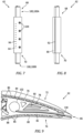
vane body 62 includes a plurality ofsensor ports 104 disposed at theleading edge 64 of the instrumentedvane body 62 each configured to receive a sensor assembly. Thesensor ports 104 are spaced apart from one another between the inner and outer radial ends 70, 68 of thevane body 62. The embodiment shown inFIG. 3 includes four (4)sensor ports 104. The number ofsensor ports 104 / sensors disposed at theleading edge 64 may vary depending on the application and the present disclosure is therefore not limited to any particular number ofsensor ports 104 / sensors. In some embodiments, thesensor ports 104 are aligned with one another along the leadingedge 64; e.g., allsensor ports 104 dissecting a line parallel with the leadingedge 64. In some embodiments, thesensor ports 104 may be aligned with the stagnation point of the leadingedge 64. Eachsensor port 104 is an aperture disposed within thevane body 62 and therefore does not extend outwardly from the leadingedge 64 of thevane body 62. This configuration mitigates or avoids core gas flow interruption that may occur with a structure that extends outwardly from the leadingedge 64. Thesensor port 104 has an inner diameter, is open to the leadingedge 64, and extends inwardly, generally perpendicular to the outer surface of the vane at theleading edge 64. As shown inFIG. 12A , eachsensor port 104 may be in communication theegress conduit 102 via arespective passage 106 that extends between therespective sensor port 104 and theegress conduit 102. The sensor itself (e.g., a thermocouple), or signal wire(s) attached to a sensor, may extend through the alignedpassage 106 and thereafter into theegress conduit 102 and thereafter out of thevane body 62 for connection with instrumentation hardware. -
FIGS. 10 and10A illustrate anexample sensor port 104 configuration with asensor 108 in the form of a sheathed Kiel temperature probe (e.g., a sheathed thermocouple) and aspacing cylinder 110 disposed within asensor port 104. The sheathedthermocouple 108 includes aforward end 112. As indicated above, thesensor 108 itself or signal wires connected to the sensor extend away from thethermocouple 108, through the alignedpassage 106 and into theegress conduit 102 and thereafter out of thevane body 62 for connection with instrumentation hardware. Thespacing cylinder 110 includes a center bore 116 with an inner diameter, an outer diameter, aforward end 118, anaft end 120, and a length ("L") extending between the forward and aft ends 118, 120. A portion of the sheathedthermocouple 108 extends through the center bore 116 of thespacing cylinder 110. Theforward end 112 of the sheathedthermocouple 108 may be disposed at a recessed distance ("R") inwardly from theopen end 122 of thesensor port 104. Theforward end 118 of thespacing cylinder 110 may be disposed at a recessed distance ("Rl") inwardly from theopen end 122 of thesensor port 104. Thespacing cylinder 110 bore inner diameter is larger than the sheathedthermocouple 108 outer diameter to permit airflow through anannular region 124 disposed therebetween. The length ("L") of thespacing cylinder 110 is preferably long enough to support and axially orient the sheathedthermocouple 108. Thespacing cylinder 110 may comprise a high temperature resistant material such as alumina, tungsten, and the like. In some embodiments, thespacing cylinder 110 may be configured to permit core gas to become entrained withinspacing cylinder 110 and/or to pass between the inner and outer diameters of thespacing cylinder 110; e.g., thespacing cylinder 110 may have perforations or be porous. Nonlimiting examples of acceptable sheathed thermocouples for gas turbine applications include Type-R, Type-S, and Type-B thermocouples. - Referring to
FIG. 11 , in some embodiments, asensor port 104 may include a plurality ofvent passages 128 disposed around the periphery of thesensor port 104. Eachvent passage 128 breaks through the inner diameter surface of thesensor port 104, extending from theopen end 122 of thesensor port 104 to a depth inward of thespacing cylinder 110. Eachvent passage 128 thereby provides a gas passage outside of the outer diameter of thespacing cylinder 110. Thevent passages 128 and theannular region 124 between the sheathedthermocouple 108 outer diameter and thespacing cylinder 110 inner diameter permits high temperature core gas to contact the inner and outer diameter surfaces of thespacing cylinder 110 to establish thermal uniformity along the length of thespacing cylinder 110. Thevent passages 128 and theannular region 124 between the sheathedthermocouple 108 outer diameter and thespacing cylinder 110 inner diameter also facilitate a pressure difference across thesensor port 104. - As stated above, the present disclosure is not limited to using thermocouples for sensing the core gas flow, and also not limited to using Kiel probes.
Alternative sensors 108 include, but are not limited to, pressure sensors (e.g., a pressure tap that includes a small diameter tube in communication with a pressure gauge from which total pressure may be measured, or a small tube configured to collect core gas specimens from which species within the core gas can be identified and/or measured, one or two platinum wire cables passed through a double hole alumina support cylinder, from which a two, three, or four wire resistance temperature detector (RTD) junction can be located within a Kiel probe head. - Referring to
FIGS. 9 and12A , in some embodiments the instrumentedvane body 62 may include a plurality of trailing edge vents 130 extending between theegress conduit 102 and the trailingedge 66 to permit the passage of high temperature core gas within theegress conduit 102 to pass through the trailingvents 130 and exit thevane body 62. Referring toFIG. 12A , in some embodiments one or more of the trailing edge vents 130 may be configured to produce a back pressure in core gas exiting through the trailingedge vent 130; e.g., the trailing edge vent may include aregion 132 disposed proximate the trailingedge 66 where the cross-sectional area of the trailingedge vent 130 decreases. - Referring to
FIG. 4 , in some embodiments the instrumentedvane body 62 may includestructural elements 134 that extend within the interior cavity 90 (e.g., from the suction side inner wall to the pressure side inner wall) to increase the structural integrity of thevane body 62. Thestructural elements 134 are configured to freely permit the flow of cooling air within theinterior cavity 90. - The present disclosure instrumented
vane body 62 may be formed using a variety of different methods. A nonlimiting example of a manufacturing method that may be used to form the instrumentedvane body 62 is additive manufacturing. The complexity of the various features and tortuous path of the cooling and venting passageways within thevane body 62 make additive manufacturing an attractive, low cost, but not required, manufacturing methodology. Using an additive manufacturing process, thevane body 62 may be manufactured with a high temperature alloys like Inconel 625, Inconel 718, Hastelloy, and the like, and can be heat treated to attain near wrought metal properties with similar heat treatment. Nonlimiting alternative manufacturing process that may be used include casting processes (e.g., lost casting) or conventional machining and welding. - As stated above, one or more
instrumented vane bodies 62 may be installed in a stator vane assembly 52 (e.g., a turbine stator vane assembly) of a production gas turbine engine or a gas turbine engine test rig. Once installed, the instrumentedvane body 62 is disposed in the same manner as any other stator vane in theassembly 52. - During operation of the
gas turbine engine 20, core gas is drawn the through the core gas path of theengine 20 and is incident to the instrumentedstator vane body 62. Cooling air (e.g., pressurized cooling air bled from a compressor section 30) is routed into theinterior cavity 90 of the instrumentedvane body 62 via thesupply conduit 100. The cooling air now disposed within theinterior cavity 90 passes through the innerwall cooling apertures 98 and enters thesuction side passage 84 and thepressure side passage 88. The innerwall cooling apertures 98 may be configured to produce impingement cooling of the respectiveouter wall leading edge 64. As stated above, the suction side andpressure side passages vent apertures 92 disposed at the trailingedge 66 to permit the egress of cooling air from thevane body 62. A difference in pressure provides the motive force to drive the cooling air through the suction side andpressure side passages vent apertures 92 disposed at the trailingedge 66. During the passage through the suction side andpressure side passages passages support members 86 provide heat transfer surfaces to remove thermal energy from theouter wall pressure side passages apertures outer walls pressure side passages wall cooling apertures outer walls - During operation of the
gas turbine engine 20, the high temperature core gas incident to the leadingedge 64 of the instrumentedvane body 62 will encounter thesensor ports 104 /sensors 108. High temperature core gas encountering arespective sensor port 104 /sensor 108 will enter thesensor port 104 and encounter theforward end 118 of thespacing cylinder 110. In those embodiments that include a sheathedthermocouple 108 recessed slightly (distance "R") from theopen end 122 of the sensor port 104 (e.g., as shown inFIG. 10 ), it is understood that core gas encountering theforward end 118 of thespacing cylinder 110 will become near stagnant, and will subsequently pass through theannular region 124 between the outer diameter of the sheathedthermocouple 108 and the inner diameter of the spacing cylinder center bore 116. Core gas passing through theannular region 124 between the sheathedthermocouple 108 and the spacing cylinder center bore 116 will subsequently pass into thepassage 106 connecting thesensor port 104 and theegress conduit 102. In those embodiments including sensor port ventpassages 128 disposed radially outside of thespacing cylinder 110, core gas passing therethrough will also subsequently pass into thepassage 106 connecting thesensor port 104 and theegress conduit 102. Regardless of whether the core gas passing through thesensor port 104 includes only that passing through theannular region 124 between the sheathedthermocouple 108 and the spacing cylinder center bore 116, or whether it also includes core gas passing through the sensor port ventpassages 128, the core gas traveling therethrough will increase the uniformity of the thermal environment sensed by the sheathedthermocouple 108 along the length of thethermocouple 108, mitigate temperature differences between the forward and aft ends of thethermocouple 108, facilitate maintaining a pressure difference across thesensor port 104, and provide a temperature reading at or near the total temperature of the high temperature core gas. - In the embodiment shown in
FIG. 12A , the high temperature core gas passing into theegress conduit 102 from thepassages 106 connected to thesensor ports 104 may exit the instrumentedvane body 62 through the trailing edge vents 130 extending between theegress conduit 102 and the trailingedge 66. As indicated herein, the trailing edge vents 130 may be configured in some embodiments to produce a back pressure to provide desirable core gas flow characteristics; e.g., to prevent sonic flow therethrough. The motive force required to move the core gas through thesensor ports 104,passages 106,egress conduit 102 and out the trailing edge vents 130 is understood to be provided by the pressure profile created by the core gas flow external to thevane body 62 between the leading and trailingedges leading edge 64 is understood to higher than the pressure of the core gas flow at the trailingedge 66. - The present disclosure instrumented
vane body 62 is understood to provide a distinct improvement over current instrumenting approaches. For example, the present disclosure instrumentedvane body 62 provides a structurally sound sensing body capable of withstanding high temperature core gas flow that can support multiple sensors. As another example, nature of the present disclosure instrumentedvane body 62 disposed within astator vane assembly 52 eliminates the need to place an additional structure in the core gas path and thereby reduces or eliminates flow disturbances associated with sensing devices that could affect measurement. - While the principles of the disclosure have been described above in connection with specific apparatuses and methods, it is to be clearly understood that this description is made only by way of example and not as limitation on the scope of the disclosure. Specific details are given in the above description to provide a thorough understanding of the embodiments. However, it is understood that the embodiments may be practiced without these specific details.
- It is noted that the embodiments may be described as a process which is depicted as a flowchart, a flow diagram, a block diagram, etc. Although any one of these structures may describe the operations as a sequential process, many of the operations can be performed in parallel or concurrently. In addition, the order of the operations may be rearranged. A process may correspond to a method, a function, a procedure, a subroutine, a subprogram, etc.
- The singular forms "a," "an," and "the" refer to one or more than one, unless the context clearly dictates otherwise. For example, the term "comprising a specimen" includes single or plural specimens and is considered equivalent to the phrase "comprising at least one specimen." The term "or" refers to a single element of stated alternative elements or a combination of two or more elements unless the context clearly indicates otherwise. As used herein, "comprises" means "includes." Thus, "comprising A or B," means "including A or B, or A and B," without excluding additional elements.
- It is noted that various connections are set forth between elements in the present description and drawings (the contents of which are included in this disclosure by way of reference). It is noted that these connections are general and, unless specified otherwise, may be direct or indirect and that this specification is not intended to be limiting in this respect. Any reference to attached, fixed, connected or the like may include permanent, removable, temporary, partial, full and/or any other possible attachment option.
- As used herein, the terms "comprise", "comprising", or any other variation thereof, are intended to cover a non-exclusive inclusion, such that a process, method, article, or apparatus that comprises a list of elements does not include only those elements but may include other elements not expressly listed or inherent to such process, method, article, or apparatus.
- While various inventive aspects, concepts and features of the disclosures may be described and illustrated herein as embodied in combination in the exemplary embodiments, these various aspects, concepts, and features may be used in many alternative embodiments, either individually or in various combinations and sub-combinations thereof. Unless expressly excluded herein all such combinations and sub-combinations are intended to be within the scope of the present application. Still further, while various alternative embodiments as to the various aspects, concepts, and features of the disclosures--such as alternative materials, structures, configurations, methods, devices, and components, and so on--may be described herein, such descriptions are not intended to be a complete or exhaustive list of available alternative embodiments, whether presently known or later developed. Those skilled in the art may readily adopt one or more of the inventive aspects, concepts, or features into additional embodiments and uses within the scope of the present application even if such embodiments are not expressly disclosed herein. For example, in the exemplary embodiments described above within the Detailed Description portion of the present specification, elements may be described as individual units and shown as independent of one another to facilitate the description. In alternative embodiments, such elements may be configured as combined elements. It is further noted that various method or process steps for embodiments of the present disclosure are described herein. The description may present method and/or process steps as a particular sequence. However, to the extent that the method or process does not rely on the particular order of steps set forth herein, the method or process should not be limited to the particular sequence of steps described. As one of ordinary skill in the art would appreciate, other sequences of steps may be possible. Therefore, the particular order of the steps set forth in the description should not be construed as a limitation.
Claims (15)
- An instrumented vane body (62), comprising:a suction side outer wall (76) and a suction side inner wall (78), both extending chordwise between a leading edge (64) and a trailing edge (66) and between an inner radial end (70) and an outer radial end (68), the suction side outer wall (76) and the suction side inner wall (78) spaced apart from one another forming a suction side passage (84) therebetween;a pressure side outer wall (80) and a pressure side inner wall (82), both extending chordwise between the leading edge (64) and the trailing edge (66) and between the inner radial end (70) and the outer radial end (68), the pressure side outer wall (80) and the pressure side inner wall (82) spaced apart from one another forming a pressure side passage (88) therebetween;wherein the suction side inner wall (78) and the pressure side inner wall (82) define an interior cavity (90);at least one supply conduit (100) in fluid communication with the interior cavity (90) through at least one of the inner radial end (70) or the outer radial end (68);wherein the suction side inner wall (78) is configured to permit passage of cooling air from the interior cavity (90) into the suction side passage (84), and the pressure side inner wall (82) is configured to permit passage of cooling air from the interior cavity (90) into the pressure side passage (88);wherein the suction side passage (84) and the pressure side passage (88) are in fluid communication with an exterior of the vane body (62);a plurality of sensor ports (104) disposed in the leading edge (64), spaced apart from one another between the inner radial end (70) and the outer radial end (68);a plurality of sensors (108), each sensor (108) disposed within a respective said sensor port (104);an egress conduit (102) extending within the interior cavity (90) and out of the vane body (62) at the inner radial end (70) or the outer radial end (68), or both, the egress conduit (102) in fluid communication with the sensor ports (104); anda plurality of trailing edge vents (130) extending between the egress conduit (102) and the exterior of the vane body (62) proximate the trailing edge (66), the trailing edge vents (130) configured to provide fluid communication between the egress conduit (102) and the exterior of the vane body (62).
- The instrumented vane body (62) of claim 1, wherein each sensor port (104) has an open end (122) disposed in the leading edge (64).
- The instrumented vane body (62) of claim 1 or 2, wherein each said sensor (108) has a forward end (112), and the forward end (112) of each said sensor (108) is recessed within the respective sensor port (104).
- The instrumented vane body (62) of claim 1, 2 or 3, wherein each said sensor (108) is a thermocouple.
- The instrumented vane body (62) of any preceding claim, further comprising a plurality of passages (106), each respective passage (106) extending between a respective said sensor port (104) and the egress conduit (102) and providing fluid communication therebetween.
- The instrumented vane body (62) of any preceding claim, further comprising a plurality of first support members (86) extending between the suction side outer wall (76) and the suction side inner wall (78), and a plurality of second support members (86) extending between the pressure side outer wall (80) and the pressure side inner wall (82).
- The instrumented vane body (62) of any preceding claim, wherein:the suction side inner wall (78) includes a plurality of suction side inner wall apertures (98) extending through the suction side inner wall (78), and the pressure side inner wall (82) includes a plurality of pressure side inner wall apertures (98) extending through the pressure side inner wall (82); and/orthe suction side outer wall (76) includes a plurality of suction side outer wall apertures (94) extending through the suction side outer wall (76), or the pressure side outer wall (80) includes a plurality of pressure side outer wall apertures (96) extending through the pressure side outer wall (80), or both.
- The instrumented vane body (62) of any preceding claim, wherein the egress conduit (102) is sealed airtight to prevent core gas passage out of the egress conduit (102) at the inner radial end (70), the outer radial end (68), or both.
- An instrumented vane body (62), comprising:a suction side outer wall (76) and a pressure side outer wall (80), both extending chordwise between a leading edge (64) and a trailing edge (66) and between an inner radial end (70) and an outer radial end (68);an interior cavity (90);at least one supply conduit (100) in fluid communication with the interior cavity (90), the at least one supply conduit (100) in communication with the interior cavity (90) through at least one of the inner radial end (70) or the outer radial end (68);a plurality of sensors (108);a plurality of sensor ports (104) disposed in the leading edge (64), each respective sensor port (104) configured to receive a respective sensor (108) of the plurality of sensors (108), the plurality of sensor ports (104) spaced apart from one another between the inner radial end (70) and the outer radial end (68), and each sensor port (104) in fluid communication with at least one vent aperture (92) disposed proximate the trailing edge (66), each sensor port (104) configured to permit core gas to enter that sensor part and exit the vane body (62) through the at least one vent aperture (92),wherein, optionally, each sensor port (104) has an open end (122) disposed in the leading edge (64).
- The instrumented vane body (62) of claim 9, wherein each said sensor (108) is a thermocouple having a forward end (112), and the forward end (112) of each said sensor (108) is recessed within the respective sensor port (104) a first distance (R).
- The instrumented vane body (62) of claim 10, wherein each said sensor port (104) is an aperture extending into the vane body (62) substantially perpendicular to the leading edge (64), each sensor port (104) having an open end (122) disposed in the leading edge (64) and an SP inner diameter surface; andthe instrumented vane body (62) further comprising a plurality spacing cylinders (110), each said spacing cylinder (110) disposed in a respective sensor port (104) and each spacing cylinder (110) having a length (L) that extends between a forward end (118) and an aft end (120), and a center bore (116) that extends lengthwise between the forward end (118) and the aft end (120) and has a center bore inner diameter surface;wherein a portion of each respective sensor (108) is disposed within the center bore (116) of a respective said spacing cylinder (110),wherein, optionally, the instrumented vane body (62) further comprises a plurality of sensing port vent passages (128) disposed around the periphery of each said sensor port (104), wherein each said vent passage (128) breaks through the sensor port inner diameter surface and extends into the vane body (62) beyond the spacing cylinder aft end (120).
- The instrumented vane body (62) of claim 11, wherein:the forward end (118) of each spacing cylinder (110) is recessed within the respective sensor port (104) a second distance (R1), wherein the second distance (R1) is greater than the first distance (R), and/orthe center bore (116) of each respective spacing cylinder (110) and each respective sensor (108) disposed within that said center bore (116) are configured such that an annular region (124) is disposed between the CB inner diameter surface and the respective sensor (108) to permit gas passage through the annular region (124).
- The instrumented vane body (62) of any of claims 9 to 12, further comprising:an egress conduit (102) extending within the interior cavity (90) and out of the vane body (62) at the inner radial end (70) or the outer radial end (68), or both; anda plurality of passages (106), each respective passage (106) extending between a respective said sensor port (104) and the egress conduit (102) and providing fluid communication therebetween;wherein the egress conduit (102) is in fluid communication with the at least one vent aperture (92) disposed proximate the trailing edge (66).
- The instrumented vane body (62) of any of claims 9 to 13, further comprising a suction side inner wall (78) extending chordwise between the leading edge (64) and the trailing edge (66) and between the inner radial end (70) and the outer radial end (68), and spaced apart from the suction side outer wall (76) to form a suction side passage (84) therebetween; anda pressure side inner wall (82) extending chordwise between the leading edge (64) and the trailing edge (66) and between the inner radial end (70) and the outer radial end (68), and spaced apart from the pressure side outer wall (80) to form a pressure side passage (88) therebetween; andwherein the suction side passage (84) and the pressure side passage (88) are in fluid communication with the interior cavity (90); andwherein the suction side passage (84) and the pressure side passage (88) are in fluid communication with an exterior of the vane body (62),wherein, optionally, the instrumented vane body (62) further comprises a plurality of first support members (86) extending between the suction side outer wall (76) and the suction side inner wall (78), and a plurality of second support members (86) extending between the pressure side outer wall (80) and the pressure side inner wall (82).
- A stator vane assembly (52), comprising:
a plurality of stator vanes including at least one instrumented vane body (62) of any of claims 9 to 14.
Applications Claiming Priority (1)
| Application Number | Priority Date | Filing Date | Title |
|---|---|---|---|
| US18/115,027 US12060801B1 (en) | 2023-02-28 | 2023-02-28 | Gas turbine vane body with instrumentation |
Publications (1)
| Publication Number | Publication Date |
|---|---|
| EP4439038A1 true EP4439038A1 (en) | 2024-10-02 |
Family
ID=90105227
Family Applications (1)
| Application Number | Title | Priority Date | Filing Date |
|---|---|---|---|
| EP24160229.1A Pending EP4439038A1 (en) | 2023-02-28 | 2024-02-28 | Gas turbine vane body with instrumentation |
Country Status (2)
| Country | Link |
|---|---|
| US (1) | US12060801B1 (en) |
| EP (1) | EP4439038A1 (en) |
Citations (2)
| Publication number | Priority date | Publication date | Assignee | Title |
|---|---|---|---|---|
| US20140182292A1 (en) * | 2012-12-29 | 2014-07-03 | United Technologies Corporation | Integral instrumentation in additively manufactured components of gas turbine engines |
| US10684149B2 (en) * | 2018-03-09 | 2020-06-16 | Rolls-Royce Corporation | System and method of measuring turbine vane cooling air consumption during engine operation |
Family Cites Families (10)
| Publication number | Priority date | Publication date | Assignee | Title |
|---|---|---|---|---|
| US3348414A (en) * | 1964-10-09 | 1967-10-24 | Gen Electric | Gas turbine temperature measuring apparatus |
| US3592061A (en) | 1969-08-22 | 1971-07-13 | Gen Motors Corp | Gas turbine airfoil having integral thermocouple |
| US4433584A (en) | 1981-11-27 | 1984-02-28 | United Technologies Corp. | Total pressure probe |
| US4605315A (en) * | 1984-12-13 | 1986-08-12 | United Technologies Corporation | Temperature probe for rotating machinery |
| US4595298A (en) | 1985-05-01 | 1986-06-17 | The United States Of America As Represented By The Secretary Of The Air Force | Temperature detection system for use on film cooled turbine airfoils |
| FR3012169B1 (en) * | 2013-10-21 | 2018-01-12 | Safran Aircraft Engines | INSTRUMENTED BLADE |
| FR3043775B1 (en) * | 2015-11-12 | 2017-11-10 | Snecma | DEVICE FOR MEASURING AERODYNAMIC SIZES FOR PLACING IN A FLOWING VEHIC OF A TURBOMACHINE |
| FR3065527B1 (en) | 2017-04-21 | 2020-11-20 | Safran Aircraft Engines | DEVICE FOR MEASURING PARAMETERS OF AN AERODYNAMIC FLOW OF A TURBOMACHINE, A BLADE INSTRUMENT SECTOR EQUIPPED WITH SUCH A MEASURING DEVICE AND METHOD FOR MANUFACTURING SUCH A DEVICE |
| EP3462153B1 (en) * | 2017-09-29 | 2021-09-22 | General Electric Technology GmbH | Method for determining a local hot gas temperature in a hot gas duct, and devices for carrying out the method |
| BE1026684B1 (en) * | 2018-10-05 | 2020-05-07 | Safran Aero Boosters Sa | Aircraft machine part incorporating at least one pressure sensor |
-
2023
- 2023-02-28 US US18/115,027 patent/US12060801B1/en active Active
-
2024
- 2024-02-28 EP EP24160229.1A patent/EP4439038A1/en active Pending
Patent Citations (2)
| Publication number | Priority date | Publication date | Assignee | Title |
|---|---|---|---|---|
| US20140182292A1 (en) * | 2012-12-29 | 2014-07-03 | United Technologies Corporation | Integral instrumentation in additively manufactured components of gas turbine engines |
| US10684149B2 (en) * | 2018-03-09 | 2020-06-16 | Rolls-Royce Corporation | System and method of measuring turbine vane cooling air consumption during engine operation |
Also Published As
| Publication number | Publication date |
|---|---|
| US12060801B1 (en) | 2024-08-13 |
| US20240287912A1 (en) | 2024-08-29 |
Similar Documents
| Publication | Publication Date | Title |
|---|---|---|
| EP3121382B1 (en) | Gas turbine engines including channel-cooled hooks for retaining a part relative to an engine casing structure | |
| EP3239462A1 (en) | Airfoil for a turbine engine | |
| EP3214291A1 (en) | Method and system for piping failure detection | |
| US20130071227A1 (en) | Blade outer air seal assembly leading edge core configuration | |
| EP3543473B1 (en) | Gas turbine engine having a splitter with a flush-mounted combined static pressure and temperature probe | |
| US20190330997A1 (en) | Inspection and maintenance apparatus | |
| US20050265836A1 (en) | Cooled rotor blade and method for cooling a rotor blade | |
| US20220403746A1 (en) | Cooling schemes for airfoils for gas turbine engines | |
| US20150369077A1 (en) | Suction-based active clearance control system | |
| US20160369633A1 (en) | Trench cooling of airfoil structures | |
| US7665968B2 (en) | Cooled rotor blade | |
| US10767490B2 (en) | Hot section engine components having segment gap discharge holes | |
| EP3418703B1 (en) | Air temperature sensor | |
| EP3266983B1 (en) | Cooling system for an airfoil of a gas powered turbine | |
| JP6505179B2 (en) | Exhaust gas temperature detection probe assembly | |
| EP4439038A1 (en) | Gas turbine vane body with instrumentation | |
| US20200040760A1 (en) | Airfoil core inlets in a rotating vane | |
| EP3628818B1 (en) | Impingement cooling for gas turbine engine component | |
| US4050306A (en) | Method and apparatus for measuring pressures | |
| WO2014159575A1 (en) | Gas turbine engine multi-vaned stator cooling configuration | |
| US20180216467A1 (en) | Turbine engine with an extension into a buffer cavity | |
| US10590778B2 (en) | Engine component with non-uniform chevron pins | |
| EP3564485A1 (en) | Airfoils, cores, and methods of manufacture for forming airfoils having fluidly connected platform cooling circuits | |
| US11624662B2 (en) | Exhaust gas temperature sensor | |
| US20180372558A1 (en) | Air temperature sensor and method of reducing error |
Legal Events
| Date | Code | Title | Description |
|---|---|---|---|
| PUAI | Public reference made under article 153(3) epc to a published international application that has entered the european phase |
Free format text: ORIGINAL CODE: 0009012 |
|
| STAA | Information on the status of an ep patent application or granted ep patent |
Free format text: STATUS: THE APPLICATION HAS BEEN PUBLISHED |
|
| AK | Designated contracting states |
Kind code of ref document: A1 Designated state(s): AL AT BE BG CH CY CZ DE DK EE ES FI FR GB GR HR HU IE IS IT LI LT LU LV MC ME MK MT NL NO PL PT RO RS SE SI SK SM TR |
|
| STAA | Information on the status of an ep patent application or granted ep patent |
Free format text: STATUS: REQUEST FOR EXAMINATION WAS MADE |
|
| 17P | Request for examination filed |
Effective date: 20250402 |