EP4439000A1 - Measuring device for profiled bars - Google Patents
Measuring device for profiled bars Download PDFInfo
- Publication number
- EP4439000A1 EP4439000A1 EP24166972.0A EP24166972A EP4439000A1 EP 4439000 A1 EP4439000 A1 EP 4439000A1 EP 24166972 A EP24166972 A EP 24166972A EP 4439000 A1 EP4439000 A1 EP 4439000A1
- Authority
- EP
- European Patent Office
- Prior art keywords
- measuring device
- profiled bar
- contact element
- profiled
- contact
- Prior art date
- Legal status (The legal status is an assumption and is not a legal conclusion. Google has not performed a legal analysis and makes no representation as to the accuracy of the status listed.)
- Granted
Links
Images



Classifications
-
- G—PHYSICS
- G01—MEASURING; TESTING
- G01B—MEASURING LENGTH, THICKNESS OR SIMILAR LINEAR DIMENSIONS; MEASURING ANGLES; MEASURING AREAS; MEASURING IRREGULARITIES OF SURFACES OR CONTOURS
- G01B5/00—Measuring arrangements characterised by the use of mechanical techniques
- G01B5/0002—Arrangements for supporting, fixing or guiding the measuring instrument or the object to be measured
- G01B5/0004—Supports
-
- B—PERFORMING OPERATIONS; TRANSPORTING
- B23—MACHINE TOOLS; METAL-WORKING NOT OTHERWISE PROVIDED FOR
- B23Q—DETAILS, COMPONENTS, OR ACCESSORIES FOR MACHINE TOOLS, e.g. ARRANGEMENTS FOR COPYING OR CONTROLLING; MACHINE TOOLS IN GENERAL CHARACTERISED BY THE CONSTRUCTION OF PARTICULAR DETAILS OR COMPONENTS; COMBINATIONS OR ASSOCIATIONS OF METAL-WORKING MACHINES, NOT DIRECTED TO A PARTICULAR RESULT
- B23Q17/00—Arrangements for observing, indicating or measuring on machine tools
- B23Q17/20—Arrangements for observing, indicating or measuring on machine tools for indicating or measuring workpiece characteristics, e.g. contour, dimension, hardness
-
- G—PHYSICS
- G01—MEASURING; TESTING
- G01B—MEASURING LENGTH, THICKNESS OR SIMILAR LINEAR DIMENSIONS; MEASURING ANGLES; MEASURING AREAS; MEASURING IRREGULARITIES OF SURFACES OR CONTOURS
- G01B5/00—Measuring arrangements characterised by the use of mechanical techniques
- G01B5/02—Measuring arrangements characterised by the use of mechanical techniques for measuring length, width or thickness
-
- G—PHYSICS
- G01—MEASURING; TESTING
- G01B—MEASURING LENGTH, THICKNESS OR SIMILAR LINEAR DIMENSIONS; MEASURING ANGLES; MEASURING AREAS; MEASURING IRREGULARITIES OF SURFACES OR CONTOURS
- G01B7/00—Measuring arrangements characterised by the use of electric or magnetic techniques
- G01B7/002—Constructional details of contacts for gauges actuating one or more contacts
-
- G—PHYSICS
- G01—MEASURING; TESTING
- G01B—MEASURING LENGTH, THICKNESS OR SIMILAR LINEAR DIMENSIONS; MEASURING ANGLES; MEASURING AREAS; MEASURING IRREGULARITIES OF SURFACES OR CONTOURS
- G01B7/00—Measuring arrangements characterised by the use of electric or magnetic techniques
- G01B7/004—Measuring arrangements characterised by the use of electric or magnetic techniques for measuring coordinates of points
- G01B7/008—Measuring arrangements characterised by the use of electric or magnetic techniques for measuring coordinates of points using coordinate measuring machines
- G01B7/012—Contact-making feeler heads therefor
- G01B7/016—Constructional details of contacts
-
- G—PHYSICS
- G01—MEASURING; TESTING
- G01B—MEASURING LENGTH, THICKNESS OR SIMILAR LINEAR DIMENSIONS; MEASURING ANGLES; MEASURING AREAS; MEASURING IRREGULARITIES OF SURFACES OR CONTOURS
- G01B2210/00—Aspects not specifically covered by any group under G01B, e.g. of wheel alignment, caliper-like sensors
- G01B2210/58—Wireless transmission of information between a sensor or probe and a control or evaluation unit
Definitions
- the invention relates to a measuring device for measuring profiled bars, more specifically for measuring the length of the profiled bars, that is to say, their dimension in a direction parallel to a main extension direction or longitudinal direction of each profiled bar.
- the measuring device according to the invention is suitable for being mounted in a machine for machining profiled bars, for example in a machine having an operating head which is able to perform cutting, milling, drilling and other operations on the profiled bars which involve removal of chippings.
- the measuring device according to the invention is particularly suitable for use in a machine having an operating head on which many tools different from each other can be mounted, the tools being intended to be picked up automatically by the operating head to perform the corresponding machining operation.
- the profiled bars which are presented to the operating head or which are moved away from the operating head have a known nominal length, along a main extension direction thereof. However, it may occur that, due to machining tolerances, errors in the initial dimensions of the bar, or machining errors which have occurred subsequently, the profiled bar has an actual length significantly different from the nominal length.
- the cross-section of the profiled bar is complex and the profiled bar has been cut along a cutting plane which is not perpendicular to the longitudinal direction, measuring the nominal length may be difficult. If the subsequent work operations have as a reference an end of the profiled bar arranged close to the operating head, an error in the length of the profiled bar may cause difficulties in coupling the profiled bar with other profiled bars intended to produce, for example, a door or window frame.
- Some types of machines for machining profiled bars comprise a carriage which moves back and forth in a direction parallel to a main longitudinal dimension of the profiled bars in order to perform the required machining.
- a contact plate is supported by the carriage and is selectively lowered when it is necessary to measure the length of a profiled bar. The carriage is then moved until the contact plate abuts against the free end of the profiled bar. At this point, knowing the position of the contact plate, it is possible to determine the length of the profiled bar.
- the contact plate operates in a satisfactory manner in the case of machines for machining profiled bars which have limited dimensions, it may result in drawbacks due to its significant dimensions in the case of machines of large dimensions, in which the carriage is, for example, shaped like a portal. These drawbacks are due mainly to the need to cover most of the operating field of the machine, which determines a significant size of the contact plate, with consequent difficulties in maintaining a high precision of the surface of the contact plate due to errors in planarity and structural deformations.
- a contact member having a spherical head of the type normally used for testing operations, in order to detect the position of the free end of the profiled bar.
- the contact members of this type are quite expensive and delicate and could be easily damaged if they were used to make contact with cutting edges, such as in the case of profiled bars having a free end cut at 45° relative to a longitudinal axis of the profiled bar, or profiled bars having one or more tabs which project from a perimeter zone of the profiled bar.
- the laser sensor gives repeatable measurements if it operates in constant conditions, whilst it can provide discordant measurements in the case of variations in operating conditions, for example in the colour of the profiled bar, the brightness and the like. In these cases, the laser sensor provides imprecise measurements, unless it is frequently recalibrated.
- An object of the invention is to improve the measuring devices for measuring the length of a profiled bar.
- Another object is to provide a measuring device for measuring the length of a profiled bar, which has a limited size.
- Another object is to provide a measuring device for measuring the length of a profiled bar, which has a good robustness.
- a further object is to provide a measuring device for measuring the length of a profiled bar, which provides precise measurements even when the operating conditions change.
- a measuring device for measuring a longitudinal dimension of a profiled bar comprising:
- the measuring device according to this invention is intended to be supported by the spindle of the machine for machining profiled bars in which the measuring device has to be inserted. This makes it possible to use the spindle for moving the measuring device towards the end zone of the profiled bar. In this way it is possible to obtain a measuring device having a particularly simple structure, since it is not necessary to use a dedicated movement device for moving the measuring device.
- the measuring device can easily be coupled to, and uncoupled from, the spindle of the machine for machining profiled bars, even automatically.
- the measuring device may be interchangeable with respect to a normal tool intended to be mounted on the machine for machining profiled bars.
- the sensor included in the measuring device is configured to send the signal to the receiver using a wireless connection, it is possible to avoid the use of wires which could obstruct during the movements of the spindle.
- the contact element is configured to make contact with an end zone of the profiled bar of which the longitudinal dimension is to be measured. In this way it is possible to perform a precise measurement, which is not affected by the variation of the conditions outside the measuring device, which could, on the other hand, influence the precision of other types of sensor, for example a laser sensor.
- the contact element is shaped like a contact plate configured for abutting against the end zone of the profiled bar.
- a contact plate it is possible to obtain a reliable and robust contact element, which is difficult to be damaged even when it is brought into contact with an edge or a tab of a profiled bar.
- the measuring device comprises a further contact plate, arranged at the opposite side of the contact plate relative to a body of the measuring device.
- the sensor included in the measuring device is of the piezoelectric type.
- this type of sensor provides a potential difference, which may provide the energy necessary for the wireless transmission of the signal coming from the sensor.
- the piezoelectric sensor may make the use of a battery superfluous, which considerably reduces the maintenance of the measuring device.
- Figure 1 shows a machining unit 1 of a machine for machining profiled bars.
- the profiled bars may be made of metallic materials, such as aluminium, steel or the like, synthetic polymeric materials, such as polyvinyl chloride (PVC) or composite materials.
- metallic materials such as aluminium, steel or the like
- synthetic polymeric materials such as polyvinyl chloride (PVC) or composite materials.
- the profiled bars may be intended to form door or window frames but they may also be used for other applications, such as the construction of supporting frames or other products.
- the machining unit 1 comprises an operating head 2 which is able to perform machining operations of various types, for example drilling, milling and the like, on the profiled bars.
- the operating head 2 comprises a tool holder spindle, which in the example shown is an electric spindle 3.
- the electric spindle 3 supports and rotates a tool, not illustrated, to perform the required machining operation on the profiled bar.
- the electric spindle 3 comprises a coupling element 4, suitable for shapingly coupling with a connector of the tool, for example owing to a cone-shaped coupling.
- the operating head 2 has various degrees of freedom, so as to move the electric spindle 3 towards, or alternatively move the electric spindle 3 away from, various faces of the profiled bar and perform the requested operations.
- the operating head 2, and with it the electric spindle 3, is movable forwards and backwards along a direction X, which coincides with a longitudinal direction in which the profiled bars to be machined mainly extend.
- the operating head 2, and with it the electric spindle 3, is movable along a further direction Y, which extends horizontally and is perpendicular to the direction X, as well as along a vertical direction Z, perpendicular to the direction X and to the further direction Y. This allows the operating head 2 to be positioned in the most suitable position for performing the requested operations.
- the machine for machining the profiled bars comprises at least one gripping device 8 for gripping each profiled bar and keeping it in a correct position during the machining operations performed by the operating head 2.
- Each gripping device 8 may comprise at least one pair of gripping elements 7, at least one of which is movable relative to the other along a guide 9 in a clamping direction arranged transversally, in particular perpendicularly, to the direction X.
- a gripping element 7 may alternatively move towards the other gripping element 7 of the same gripping device 8 for clamping the profiled bar, or move away from the other gripping element 7 for disengaging the profiled bar.
- each gripping device 8 of the example shown comprises a single pair of gripping elements 7. It is also possible to provide gripping devices 8 comprising several pairs of gripping elements 7, particularly if the gripping devices 8 have to support profiled bars having a significant length.
- the gripping devices 8 can also be movable along the direction X for moving away the ends of the profiled bars, leaving to the operating head 2 the space necessary for the machining operations.
- profiled bars B1 and B2 are shown, located upstream and downstream of the operating head 2.
- the profiled bar B1 is delimited by an end section 10 which may be cut at 45° relative to the direction X.
- the further profiled bar B2 is, on the other hand, delimited by a further end section 11 which may lie in a plane perpendicular to the direction X.
- profiled bars B1 and B2 may have transversal cross-sections, and respective end cross-sections, shaped differently from that shown in the drawings.
- the end section 10 of the profiled bar B1 faces towards the electric spindle 3.
- the further end section 11 of the further profiled bar B2 also faces towards the electric spindle 3.
- a measuring device 12 is furthermore provided for measuring the length of a profiled bar positioned in or close to the machining unit 1.
- the measuring device 12 is configured to detect the position of an end section 10, 11 or end zone of the profiled bar of which the length is to be measured. This allows the length of the profiled bar to be determined, since the position of the end section of the profiled bar opposite to that from which the position is detected is known.
- the measuring device 12 comprises a box-shaped body 13, shown in particular in Figure 3 .
- the box-shaped body 13 may be removably fixed to the electric spindle 3 owing to a connector 6 included in the measuring device 12.
- the connector 6 projects from a surface of the box-shaped body 13, in particular from an upper surface 14 of the latter.
- the connector 6 is capable of shapingly coupling with the coupling element 4 of the electric spindle 3.
- the connector 6 uses the same type of coupling by which a tool can be removably fixed to the electric spindle 3.
- the measuring device 12 may therefore be mounted on the electric spindle 3 so as to be interchangeable with the tools which are used by the operating head 2 for machining the profiled bar, that is to say, in place of the tools.
- a pin 15 projects from the box-shaped body 13, in particular from the upper surface 14, the pin 15 being suitable for engaging in a hole, not illustrated, made in the electric spindle 3.
- the pin 15 acts as an anti-rotation element, preventing the box-shaped body 13 from rotating relative to the electric spindle 3.
- the measuring device 12 further comprises at least one contact element 16 intended to abut against the end section of the profiled bar of which the length is to be measured.
- the contact element 16 is intended to make contact with the end section 10 of the profiled bar B1.
- the contact element 16 is delimited by a contact surface 17 for coming into contact with the end section of the profiled bar to be measured.
- the contact surface 17 may be a flat surface extending transversally, in particular perpendicularly, to the direction X.
- the contact element 16 may be shaped like a plate.
- a further contact element 18 is provided, the further contact element 18 being arranged at the opposite side of the box-shaped body 13 relative to the contact element 16.
- the contact element 16 and the further contact element 18 extend from opposite faces of the box-shaped body 13, so that the box-shaped body 13 is interposed between the contact element 16 and the further contact element 18.
- the further contact element 18 is delimited by a further contact surface 19, which may be flat and which extends transversally, in particular perpendicularly, to the direction X. According to the example shown, the further contact element 18 is suitable for abutting against the further end section 11 of the profiled bar B2, so as to measure the length thereof.
- the measuring device 12 is thus able to measure the length of two different profiled bars B1 and B2, arranged at opposite sides of the operating head 2, owing to the contact element 16 and the further contact element 18. This makes it possible to measure the length of two profiled bars B1 and B2, located, respectively, upstream and downstream of the operating head 2, without moving the profiled bars B1 and B2.
- the measuring device 12 for interacting with both the ends of a single profiled bar, in the case, for example, of a profiled bar having been cut or the position of any end of the profiled bar not being precisely known.
- the contact element 16 is used on one of the ends and the further contact element 18 on the other end, after repositioning the operating head 2.
- the measuring device 12 may have a single contact element, for example the contact element 16, whilst the further contact element 18 is not provided.
- the measuring device 12 further comprises a sensor 20, more clearly visible in Figure 3 , which may comprise a piezoelectric element.
- the sensor 20 is fixed to the box-shaped body 13.
- the sensor 20 comprises a body 21, which houses the piezoelectric element, from which a pin 22 protrudes.
- the pin 22 extends vertically.
- the pin 22 can move vertically relative to the body 21 of the sensor 20.
- the pin 22 can be pushed towards the outside of the body 21 by an elastic element, not illustrated, and can move towards the inside of the body 21 when the elastic element is compressed.
- a cam follower element 23 is fixed to one end of the pin 22 located outside the body 21, in particular at the lower end of the pin 22.
- the cam follower element 23 is shaped like a wheel which is free to rotate about a respective axis, for example arranged horizontally.
- the pin 22 and the cam follower element 23 are arranged inside the box-shaped body 13.
- the measuring device 12 further comprises a control rod 24 which may extend parallel to the direction X, that is to say, horizontally.
- the control rod 24 has a first end 25, fixed relative to the contact element 16.
- a second end 27 of the control rod 24 is, on the other hand, fixed relative to the further contact element 18.
- the control rod 24 has, in a central region thereof, a narrowing 33 defining a cam profile 28.
- the cam follower element 23 is normally positioned at the centre of the narrowing 33.
- the control rod 24 is supported by a pair of bushings 29, for example of the recirculating ball type, which are fixed relative to the box-shaped body 13.
- the control rod 24 is slidable in the direction X relative to the bushings 29, and is therefore slidable relative to the box-shaped body 13.
- the senor 20 comprises a piezoelectric element, positioned in such a way as to be deformed when the pin 22 is moved along the direction Z, in particular towards the inside of the body 21. When this happens, a potential difference is generated due to the piezoelectric effect.
- a transmitter not illustrated, is also provided, the transmitter being housed inside the box-shaped body 13 and being suitable for communicating with a receiver, not illustrated.
- the receiver is outside the measuring device 12. More specifically, the transmitter is configured for sending a signal to the receiver when the piezoelectric element is deformed, which - as described in more detail below - indicates that an end section of the profiled bar to be measured has been identified.
- the transmitter can be powered electrically owing to the potential difference generated by the piezoelectric element. This makes it unnecessary, in the majority of cases, to use a battery which would be expensive, bulky and require relatively frequent maintenance.
- the transmitter is configured for communicating with the receiver by a wireless connection, for example by a radio connection. This prevents the use of electrical cables for connecting the transmitter to the receiver, which could be troublesome when the operating head 2 is moved.
- the measuring device 12 further comprises a shaft 30, which connects the contact element 16 and the further contact element 18 in an upper region thereof.
- the shaft 30 is supported by a pair of sliding bushings 31, which make it possible for the shaft 30 to move in the direction X relative to the box-shaped body 13.
- control rod 24 and the shaft 30 have respective end regions which protrude from opposite parts of the box-shaped body 13 to engage with the contact element 16 and, respectively, with the further contact element 18.
- Elastic means 32 are provided long the shaft 30 for generating a preloading on the contact element 16 and on the further contact element 18.
- the elastic means 32 also aim to return the contact element 16 and the further contact element 18 to a rest position, when those contact elements move away from the corresponding profiled bar after identifying its end section. In the rest position, the pin 22 included in the sensor 20 is positioned at the central section of the narrowing 33.
- the measuring device 12 When it is required to measure the length of a profiled bar, for example of the profiled bar B1, the measuring device 12 is mounted on the electric spindle 3, by coupling the connector 6 with the coupling element 4. The measuring device 12 replaces the tool which is mounted on the electric spindle 3 when it is necessary to perform a mechanical machining on the profiled bar.
- the measuring device 12 may be mounted on the electric spindle 3 without manual intervention by the operator.
- the profiled bar B1 is in a fixed position along the direction X and is locked in this position by the gripping device 8.
- the position of the end section of the profiled bar B1 furthest from the measuring device 12 is known.
- the operating head 2 is now moved parallel to the direction X until the contact element 16 abuts against the end section 10 of the profiled bar B1, as shown in Figure 2 .
- the contact between the contact element 16 and the profiled bar B1 does not necessarily have to be occur on the entire end section 10.
- the contact element 16 may touch the profiled bar B1 even only along an edge, as shown in Figure 2 .
- the cam follower element 23 moves along the cam profile 28, moving away from the central section of the narrowing 33. Consequently, the cam follower element 23 rises along the vertical direction Z and the pin 22 penetrates partly inside the body 21 of the sensor. In this way, the pin 22 deforms the piezoelectric element, for example by compressing it.
- the piezoelectric element Due to the deformation, the piezoelectric element generates a potential difference. This indicates that the contact element 16 has made contact against the end section 10 of the profiled bar B1, which allows the position of the end section 10 to be uniquely determined, in order to calculate the length of the profiled bar B1.
- the potential difference generated by the piezoelectric element makes it possible to electrically power the transmitter included in the measuring device 12, so that the latter can transmit the signal to an external receiver, using the wireless connection.
- a control unit of the machine for machining profiled bars connected to the receiver, may thereby be informed that the contact element 16 has reached the end section 10 of the profiled bar B1. From the knowledge of the position of the contact element 16 when the end section 10 is touched, it is possible to calculate the length of the profiled bar.
- the further contact element 18, if present, operates in the same way when determining the length of a profiled bar B2 facing the further contact element 18.
- a single measuring device 12 is able to perform operations for measuring the profiled bars at two opposite faces, which makes the measuring device 12 particularly versatile.
Landscapes
- Physics & Mathematics (AREA)
- General Physics & Mathematics (AREA)
- Engineering & Computer Science (AREA)
- Mechanical Engineering (AREA)
- A Measuring Device Byusing Mechanical Method (AREA)
- Measurement Of Length, Angles, Or The Like Using Electric Or Magnetic Means (AREA)
Abstract
Description
- The invention relates to a measuring device for measuring profiled bars, more specifically for measuring the length of the profiled bars, that is to say, their dimension in a direction parallel to a main extension direction or longitudinal direction of each profiled bar.
- The measuring device according to the invention is suitable for being mounted in a machine for machining profiled bars, for example in a machine having an operating head which is able to perform cutting, milling, drilling and other operations on the profiled bars which involve removal of chippings.
- The measuring device according to the invention is particularly suitable for use in a machine having an operating head on which many tools different from each other can be mounted, the tools being intended to be picked up automatically by the operating head to perform the corresponding machining operation.
- The profiled bars which are presented to the operating head or which are moved away from the operating head have a known nominal length, along a main extension direction thereof. However, it may occur that, due to machining tolerances, errors in the initial dimensions of the bar, or machining errors which have occurred subsequently, the profiled bar has an actual length significantly different from the nominal length.
- Moreover, if the cross-section of the profiled bar is complex and the profiled bar has been cut along a cutting plane which is not perpendicular to the longitudinal direction, measuring the nominal length may be difficult. If the subsequent work operations have as a reference an end of the profiled bar arranged close to the operating head, an error in the length of the profiled bar may cause difficulties in coupling the profiled bar with other profiled bars intended to produce, for example, a door or window frame.
- For these reasons, it is worth measuring precisely the length of the profiled bar which is arranged close to the operating head.
- This may be done by detecting the position of a free end of the profiled bar, which allows the length to be known if the position of the other end is known.
- Some types of machines for machining profiled bars comprise a carriage which moves back and forth in a direction parallel to a main longitudinal dimension of the profiled bars in order to perform the required machining. A contact plate is supported by the carriage and is selectively lowered when it is necessary to measure the length of a profiled bar. The carriage is then moved until the contact plate abuts against the free end of the profiled bar. At this point, knowing the position of the contact plate, it is possible to determine the length of the profiled bar.
- Although the contact plate operates in a satisfactory manner in the case of machines for machining profiled bars which have limited dimensions, it may result in drawbacks due to its significant dimensions in the case of machines of large dimensions, in which the carriage is, for example, shaped like a portal. These drawbacks are due mainly to the need to cover most of the operating field of the machine, which determines a significant size of the contact plate, with consequent difficulties in maintaining a high precision of the surface of the contact plate due to errors in planarity and structural deformations.
- In order to overcome the drawbacks due to the significant dimensions of the contact plate supported by the portal, it has been thought to use a contact member having a spherical head, of the type normally used for testing operations, in order to detect the position of the free end of the profiled bar. However, the contact members of this type are quite expensive and delicate and could be easily damaged if they were used to make contact with cutting edges, such as in the case of profiled bars having a free end cut at 45° relative to a longitudinal axis of the profiled bar, or profiled bars having one or more tabs which project from a perimeter zone of the profiled bar.
- Another possibility which has been considered consists in using a laser sensor for detecting the position of the free end of the profiled bar. The laser sensor gives repeatable measurements if it operates in constant conditions, whilst it can provide discordant measurements in the case of variations in operating conditions, for example in the colour of the profiled bar, the brightness and the like. In these cases, the laser sensor provides imprecise measurements, unless it is frequently recalibrated.
- Some examples of measuring devices of known type are disclosed in
EP 4006479 ,US 2013/027026 ,CN 112284355 ,US 5249366 . - An object of the invention is to improve the measuring devices for measuring the length of a profiled bar.
- Another object is to provide a measuring device for measuring the length of a profiled bar, which has a limited size.
- Another object is to provide a measuring device for measuring the length of a profiled bar, which has a good robustness.
- A further object is to provide a measuring device for measuring the length of a profiled bar, which provides precise measurements even when the operating conditions change.
- According to the invention, there is provided a measuring device for measuring a longitudinal dimension of a profiled bar, the measuring device comprising:
- a removable connector suitable for removably engaging in a spindle of a machine for machining profiled bars, so that the spindle supports the measuring device,
- a contact element for abutting against an end zone of a profiled bar,
- a sensor for generating a signal when the contact element has come into contact with the end zone and for sending the signal to a receiver through a wireless connection.
- Owing to the invention, it is possible to obtain a measuring device having a simple structure, which is able to effectively measure a longitudinal dimension of a profiled bar.
- The measuring device according to this invention is intended to be supported by the spindle of the machine for machining profiled bars in which the measuring device has to be inserted. This makes it possible to use the spindle for moving the measuring device towards the end zone of the profiled bar. In this way it is possible to obtain a measuring device having a particularly simple structure, since it is not necessary to use a dedicated movement device for moving the measuring device.
- Moreover, owing to the removable connector, the measuring device can easily be coupled to, and uncoupled from, the spindle of the machine for machining profiled bars, even automatically. The measuring device may be interchangeable with respect to a normal tool intended to be mounted on the machine for machining profiled bars.
- Since the sensor included in the measuring device is configured to send the signal to the receiver using a wireless connection, it is possible to avoid the use of wires which could obstruct during the movements of the spindle.
- The contact element is configured to make contact with an end zone of the profiled bar of which the longitudinal dimension is to be measured. In this way it is possible to perform a precise measurement, which is not affected by the variation of the conditions outside the measuring device, which could, on the other hand, influence the precision of other types of sensor, for example a laser sensor.
- In an embodiment, the contact element is shaped like a contact plate configured for abutting against the end zone of the profiled bar.
- Using a contact plate, it is possible to obtain a reliable and robust contact element, which is difficult to be damaged even when it is brought into contact with an edge or a tab of a profiled bar.
- In an embodiment, the measuring device comprises a further contact plate, arranged at the opposite side of the contact plate relative to a body of the measuring device.
- This makes it possible to use the measuring device for measuring the length of two profiled bars located on opposite sides of the measuring device, that is to say, downstream and upstream of the measuring device, without having to move the profiled bars to be measured.
- In an embodiment, the sensor included in the measuring device is of the piezoelectric type.
- During operation, this type of sensor provides a potential difference, which may provide the energy necessary for the wireless transmission of the signal coming from the sensor.
- In this way a measuring device is obtained which has low energy consumption and a particularly high energy efficiency.
- Moreover, the piezoelectric sensor may make the use of a battery superfluous, which considerably reduces the maintenance of the measuring device.
- The invention can be better understood and implemented with reference to the accompanying drawings which illustrate a non-limiting example embodiment of it and wherein:
-
Figure 1 is a perspective view showing an operating zone of a machine for machining profiled bars, in which a measuring device is provided for measuring the length of the profiled bars; -
Figure 2 is a front view of the operating zone ofFigure 1 ; -
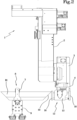
Figure 3 is an enlarged perspective view showing the measuring device ofFigure 1 ; -
Figure 4 is a view like that ofFigure 3 , wherein some parts have been omitted to make visible the inside of the measuring device. -
Figure 1 shows amachining unit 1 of a machine for machining profiled bars. - The profiled bars may be made of metallic materials, such as aluminium, steel or the like, synthetic polymeric materials, such as polyvinyl chloride (PVC) or composite materials.
- The profiled bars may be intended to form door or window frames but they may also be used for other applications, such as the construction of supporting frames or other products.
- The
machining unit 1 comprises anoperating head 2 which is able to perform machining operations of various types, for example drilling, milling and the like, on the profiled bars. - The
operating head 2 comprises a tool holder spindle, which in the example shown is anelectric spindle 3. - When there is a profiled bar to be machined in the
machining unit 1, theelectric spindle 3 supports and rotates a tool, not illustrated, to perform the required machining operation on the profiled bar. For this purpose, theelectric spindle 3 comprises acoupling element 4, suitable for shapingly coupling with a connector of the tool, for example owing to a cone-shaped coupling. - The
operating head 2 has various degrees of freedom, so as to move theelectric spindle 3 towards, or alternatively move theelectric spindle 3 away from, various faces of the profiled bar and perform the requested operations. - More specifically, the
operating head 2, and with it theelectric spindle 3, is movable forwards and backwards along a direction X, which coincides with a longitudinal direction in which the profiled bars to be machined mainly extend. - Moreover, the
operating head 2, and with it theelectric spindle 3, is movable along a further direction Y, which extends horizontally and is perpendicular to the direction X, as well as along a vertical direction Z, perpendicular to the direction X and to the further direction Y. This allows theoperating head 2 to be positioned in the most suitable position for performing the requested operations. - The machine for machining the profiled bars comprises at least one
gripping device 8 for gripping each profiled bar and keeping it in a correct position during the machining operations performed by theoperating head 2. Eachgripping device 8 may comprise at least one pair ofgripping elements 7, at least one of which is movable relative to the other along aguide 9 in a clamping direction arranged transversally, in particular perpendicularly, to the direction X. - Thus, a gripping
element 7 may alternatively move towards the other grippingelement 7 of thesame gripping device 8 for clamping the profiled bar, or move away from the other grippingelement 7 for disengaging the profiled bar. - According to the example shown, two
gripping devices 8 are provided, the gripping devices being arranged, respectively, upstream and downstream of themachining unit 1 along the direction X. Eachgripping device 8 of the example shown comprises a single pair ofgripping elements 7. It is also possible to providegripping devices 8 comprising several pairs ofgripping elements 7, particularly if thegripping devices 8 have to support profiled bars having a significant length. - The
gripping devices 8 can also be movable along the direction X for moving away the ends of the profiled bars, leaving to the operatinghead 2 the space necessary for the machining operations. - In the example shown, two profiled bars B1 and B2 are shown, located upstream and downstream of the operating
head 2. The profiled bar B1 is delimited by anend section 10 which may be cut at 45° relative to the direction X. The further profiled bar B2 is, on the other hand, delimited by afurther end section 11 which may lie in a plane perpendicular to the direction X. - It is understood that the profiled bars B1 and B2 may have transversal cross-sections, and respective end cross-sections, shaped differently from that shown in the drawings.
- The
end section 10 of the profiled bar B1 faces towards theelectric spindle 3. Thefurther end section 11 of the further profiled bar B2 also faces towards theelectric spindle 3. - A measuring
device 12 is furthermore provided for measuring the length of a profiled bar positioned in or close to themachining unit 1. - The measuring
device 12 is configured to detect the position of anend section - The measuring
device 12 comprises a box-shapedbody 13, shown in particular inFigure 3 . The box-shapedbody 13 may be removably fixed to theelectric spindle 3 owing to a connector 6 included in the measuringdevice 12. The connector 6 projects from a surface of the box-shapedbody 13, in particular from anupper surface 14 of the latter. The connector 6 is capable of shapingly coupling with thecoupling element 4 of theelectric spindle 3. For this purpose, the connector 6 uses the same type of coupling by which a tool can be removably fixed to theelectric spindle 3. The measuringdevice 12 may therefore be mounted on theelectric spindle 3 so as to be interchangeable with the tools which are used by the operatinghead 2 for machining the profiled bar, that is to say, in place of the tools. - A
pin 15 projects from the box-shapedbody 13, in particular from theupper surface 14, thepin 15 being suitable for engaging in a hole, not illustrated, made in theelectric spindle 3. Thepin 15 acts as an anti-rotation element, preventing the box-shapedbody 13 from rotating relative to theelectric spindle 3. - The measuring
device 12 further comprises at least onecontact element 16 intended to abut against the end section of the profiled bar of which the length is to be measured. According to the example shown, thecontact element 16 is intended to make contact with theend section 10 of the profiled bar B1. - The
contact element 16 is delimited by acontact surface 17 for coming into contact with the end section of the profiled bar to be measured. Thecontact surface 17 may be a flat surface extending transversally, in particular perpendicularly, to the direction X. - The
contact element 16 may be shaped like a plate. - In the example shown, a
further contact element 18 is provided, thefurther contact element 18 being arranged at the opposite side of the box-shapedbody 13 relative to thecontact element 16. In other words, thecontact element 16 and thefurther contact element 18 extend from opposite faces of the box-shapedbody 13, so that the box-shapedbody 13 is interposed between thecontact element 16 and thefurther contact element 18. - The
further contact element 18 is delimited by afurther contact surface 19, which may be flat and which extends transversally, in particular perpendicularly, to the direction X. According to the example shown, thefurther contact element 18 is suitable for abutting against thefurther end section 11 of the profiled bar B2, so as to measure the length thereof. - The measuring
device 12 is thus able to measure the length of two different profiled bars B1 and B2, arranged at opposite sides of the operatinghead 2, owing to thecontact element 16 and thefurther contact element 18. This makes it possible to measure the length of two profiled bars B1 and B2, located, respectively, upstream and downstream of the operatinghead 2, without moving the profiled bars B1 and B2. - It is also possible to use the measuring
device 12 for measuring only one profiled bar, as shown inFigure 2 . In this case, one of the twocontact elements - Moreover, it is possible to use the measuring
device 12 for interacting with both the ends of a single profiled bar, in the case, for example, of a profiled bar having been cut or the position of any end of the profiled bar not being precisely known. In this case, thecontact element 16 is used on one of the ends and thefurther contact element 18 on the other end, after repositioning theoperating head 2. - In an alternative embodiment not illustrated, the measuring
device 12 may have a single contact element, for example thecontact element 16, whilst thefurther contact element 18 is not provided. - The measuring
device 12 further comprises asensor 20, more clearly visible inFigure 3 , which may comprise a piezoelectric element. Thesensor 20 is fixed to the box-shapedbody 13. Thesensor 20 comprises abody 21, which houses the piezoelectric element, from which apin 22 protrudes. In the example shown, thepin 22 extends vertically. Thepin 22 can move vertically relative to thebody 21 of thesensor 20. In particular, thepin 22 can be pushed towards the outside of thebody 21 by an elastic element, not illustrated, and can move towards the inside of thebody 21 when the elastic element is compressed. - A
cam follower element 23 is fixed to one end of thepin 22 located outside thebody 21, in particular at the lower end of thepin 22. In the example illustrated, thecam follower element 23 is shaped like a wheel which is free to rotate about a respective axis, for example arranged horizontally. - The
pin 22 and thecam follower element 23 are arranged inside the box-shapedbody 13. - The measuring
device 12 further comprises acontrol rod 24 which may extend parallel to the direction X, that is to say, horizontally. Thecontrol rod 24 has afirst end 25, fixed relative to thecontact element 16. Asecond end 27 of thecontrol rod 24 is, on the other hand, fixed relative to thefurther contact element 18. - The
control rod 24 has, in a central region thereof, a narrowing 33 defining acam profile 28. - The
cam follower element 23 is normally positioned at the centre of the narrowing 33. - The
control rod 24 is supported by a pair ofbushings 29, for example of the recirculating ball type, which are fixed relative to the box-shapedbody 13. - The
control rod 24 is slidable in the direction X relative to thebushings 29, and is therefore slidable relative to the box-shapedbody 13. - As mentioned above, the
sensor 20 comprises a piezoelectric element, positioned in such a way as to be deformed when thepin 22 is moved along the direction Z, in particular towards the inside of thebody 21. When this happens, a potential difference is generated due to the piezoelectric effect. - A transmitter, not illustrated, is also provided, the transmitter being housed inside the box-shaped
body 13 and being suitable for communicating with a receiver, not illustrated. The receiver is outside the measuringdevice 12. More specifically, the transmitter is configured for sending a signal to the receiver when the piezoelectric element is deformed, which - as described in more detail below - indicates that an end section of the profiled bar to be measured has been identified. - The transmitter can be powered electrically owing to the potential difference generated by the piezoelectric element. This makes it unnecessary, in the majority of cases, to use a battery which would be expensive, bulky and require relatively frequent maintenance.
- The transmitter is configured for communicating with the receiver by a wireless connection, for example by a radio connection. This prevents the use of electrical cables for connecting the transmitter to the receiver, which could be troublesome when the operating
head 2 is moved. - The measuring
device 12 further comprises ashaft 30, which connects thecontact element 16 and thefurther contact element 18 in an upper region thereof. Theshaft 30 is supported by a pair of slidingbushings 31, which make it possible for theshaft 30 to move in the direction X relative to the box-shapedbody 13. - The
control rod 24 and theshaft 30 have respective end regions which protrude from opposite parts of the box-shapedbody 13 to engage with thecontact element 16 and, respectively, with thefurther contact element 18. - Elastic means 32, partly visible in
Figure 4 , are provided long theshaft 30 for generating a preloading on thecontact element 16 and on thefurther contact element 18. The elastic means 32 also aim to return thecontact element 16 and thefurther contact element 18 to a rest position, when those contact elements move away from the corresponding profiled bar after identifying its end section. In the rest position, thepin 22 included in thesensor 20 is positioned at the central section of the narrowing 33. - When it is required to measure the length of a profiled bar, for example of the profiled bar B1, the measuring
device 12 is mounted on theelectric spindle 3, by coupling the connector 6 with thecoupling element 4. The measuringdevice 12 replaces the tool which is mounted on theelectric spindle 3 when it is necessary to perform a mechanical machining on the profiled bar. - If the operating
head 2 is able to automatically pick up the tools from a storage area, the measuringdevice 12 may be mounted on theelectric spindle 3 without manual intervention by the operator. - The profiled bar B1 is in a fixed position along the direction X and is locked in this position by the
gripping device 8. The position of the end section of the profiled bar B1 furthest from the measuringdevice 12 is known. - The operating
head 2 is now moved parallel to the direction X until thecontact element 16 abuts against theend section 10 of the profiled bar B1, as shown inFigure 2 . The contact between thecontact element 16 and the profiled bar B1 does not necessarily have to be occur on theentire end section 10. Depending on the geometry of theend section 10, thecontact element 16 may touch the profiled bar B1 even only along an edge, as shown inFigure 2 . - While continuing to push the
contact element 16 towards the profiled bar B1, thecontact element 16 is pushed towards the box-shapedbody 13, which remains in a fixed position along the direction X. The elastic means 32 are consequently compressed. - The
control rod 24, which is fixed relative to thecontact element 16, moves parallel to the direction X, whilst thesensor 20 remains in a fixed position along the direction X. - The
cam follower element 23 moves along thecam profile 28, moving away from the central section of the narrowing 33. Consequently, thecam follower element 23 rises along the vertical direction Z and thepin 22 penetrates partly inside thebody 21 of the sensor. In this way, thepin 22 deforms the piezoelectric element, for example by compressing it. - Due to the deformation, the piezoelectric element generates a potential difference. This indicates that the
contact element 16 has made contact against theend section 10 of the profiled bar B1, which allows the position of theend section 10 to be uniquely determined, in order to calculate the length of the profiled bar B1. - Moreover, the potential difference generated by the piezoelectric element makes it possible to electrically power the transmitter included in the measuring
device 12, so that the latter can transmit the signal to an external receiver, using the wireless connection. - A control unit of the machine for machining profiled bars, connected to the receiver, may thereby be informed that the
contact element 16 has reached theend section 10 of the profiled bar B1. From the knowledge of the position of thecontact element 16 when theend section 10 is touched, it is possible to calculate the length of the profiled bar. - The operating
head 2 is moved along the direction X owing to one or more actuators to which are associated position transducers, not shown, which allow the position of the actuators and, therefore, of the operatinghead 2 to be known with precision. Since the measuringdevice 12 is mounted on theelectric spindle 3 which is supported by the operatinghead 2, by knowing the position of the actuators it is possible to determine the position of thecontact element 16 or thefurther contact element 18, when thecontact element 16 or thefurther contact element 18 touches the end of the corresponding profiled bar. - The
further contact element 18, if present, operates in the same way when determining the length of a profiled bar B2 facing thefurther contact element 18. - In this way, a
single measuring device 12 is able to perform operations for measuring the profiled bars at two opposite faces, which makes the measuringdevice 12 particularly versatile.
Claims (14)
- A measuring device for measuring a longitudinal dimension of a profiled bar (B1, B2), comprising:- a removable connector (6) suitable for removably engaging in a spindle (3) of a machine for machining profiled bars, so that the spindle (3) supports the measuring device (12),- at least one contact element (16) for abutting against an end zone (10) of a profiled bar,- a sensor (20) for generating a signal when the contact element (16) has come into contact with the end zone (10) and for sending the signal to a receiver through a wireless connection,characterised in that the contact element (16) is shaped like a plate delimited by a substantially flat contact surface (17), the contact surface (17) being suitable for abutting against the end zone (10) of the profiled bar, the contact surface (17) extending transversely to the longitudinal dimension of the profiled bar.
- The measuring device according to claim 1, wherein the sensor (20) comprises a piezoelectric element.
- The measuring device according to claim 2, and further comprising a transmitter for transmitting said signal to the receiver, the piezoelectric element being connected to the transmitter so that the difference in potential generated by the piezoelectric element powers the transmitter.
- The measuring device according to claim 2 or 3, and further comprising a control element (24) fixed relative to the contact element (16) and having a cam profile (28), wherein the sensor (20) comprises a cam follower element (23) which engages with the cam profile (28) so as to deform the piezoelectric element when the contact element (16) touches the end zone (10) of the profiled bar.
- The measuring device according to claim 4, wherein the control element comprises a control rod (24) which extends parallel to the longitudinal dimension of the profiled bar, the control rod (24) having a transversal cross-section which has a variation in cross-section (33) that defines the cam profile (28).
- The measuring device according to claim 5, wherein the sensor (20) comprises a body (21) in which the piezoelectric element is housed, the sensor (20) further comprising a pin (22) which protrudes from the body (21) and is slidable relative to the body (21) transversely to the longitudinal dimension of the profiled bar, the cam follower element (23) being provided at an end of the pin (22).
- The measuring device according to claim 5 or 6, wherein the variation in cross-section of the control rod (24) comprises a narrowing of cross-section (33) and wherein the cam follower element (23) is received in the narrowing of cross-section (33) in an inactive configuration in which the contact element (16) is detached from the end zone (10) of the profiled bar.
- The measuring device according to any preceding claim, wherein the contact surface (17) extends perpendicularly to the longitudinal dimension of the profiled bar.
- The measuring device according to any preceding claim, and further comprising a further contact element (18) for abutting against a further end zone (11) of a further profiled bar, the sensor (20) being interposed between the contact element (16) and the further contact element (18) relative to a direction parallel to the longitudinal dimension of the profiled bar.
- The measuring device according to claim 9, wherein the further contact element comprises a further plate (18) delimited by a further contact surface (19) which is substantially flat and is suitable for abutting against the further end zone (11) of the further profiled bar, the further contact surface (19) extending transversely, for example perpendicularly, to a longitudinal dimension of the further profiled bar.
- The measuring device according to claim 9 or 10, wherein the contact element (16) and the further contact element (18) are rigidly connected to each other, so as to form an assembly in which the contact element (16) is fixed relative to the further contact element (18), said assembly being slidable relative to the sensor (20) in a direction parallel to the longitudinal dimension of the profiled bar.
- The measuring device according to any preceding claim, wherein the wireless connection is a radio connection.
- A machine for machining profiled bars, comprising an operating head (2) for performing machining operations on the profiled bars, the operating head (2) having an electric spindle (3), the machine further comprising a measuring device (12) according to any preceding claim, wherein the removable connector (6) of the measuring device (12) is coupled with the electric spindle (3).
- The machine according to claim 13, and further comprising at least one tool which can be coupled in a removable manner to the operating head (2) for performing a machining operation on a profiled bar, wherein the measuring device (12) is interchangeable with the tool.
Applications Claiming Priority (1)
| Application Number | Priority Date | Filing Date | Title |
|---|---|---|---|
| IT102023000006249A IT202300006249A1 (en) | 2023-03-31 | 2023-03-31 | MEASURING DEVICE FOR PROFILE BARS. |
Publications (2)
| Publication Number | Publication Date |
|---|---|
| EP4439000A1 true EP4439000A1 (en) | 2024-10-02 |
| EP4439000B1 EP4439000B1 (en) | 2025-12-10 |
Family
ID=86851228
Family Applications (1)
| Application Number | Title | Priority Date | Filing Date |
|---|---|---|---|
| EP24166972.0A Active EP4439000B1 (en) | 2023-03-31 | 2024-03-27 | Measuring device for profiled bars |
Country Status (2)
| Country | Link |
|---|---|
| EP (1) | EP4439000B1 (en) |
| IT (1) | IT202300006249A1 (en) |
Citations (5)
| Publication number | Priority date | Publication date | Assignee | Title |
|---|---|---|---|---|
| US5249366A (en) | 1991-04-26 | 1993-10-05 | Mitutoyo Corporation | Dimension measuring instrument |
| EP2432618A1 (en) * | 2009-05-21 | 2012-03-28 | Emmegi S.P.A. | Machine tool |
| US20130027026A1 (en) | 2011-07-25 | 2013-01-31 | Reinhold Schopf | Probe Head |
| CN112284355A (en) | 2020-09-14 | 2021-01-29 | 北京致感致联科技有限公司 | Passive piezoelectric sensor and monitoring system |
| EP4006479A1 (en) | 2017-01-18 | 2022-06-01 | Renishaw PLC | Machine tool apparatus |
-
2023
- 2023-03-31 IT IT102023000006249A patent/IT202300006249A1/en unknown
-
2024
- 2024-03-27 EP EP24166972.0A patent/EP4439000B1/en active Active
Patent Citations (5)
| Publication number | Priority date | Publication date | Assignee | Title |
|---|---|---|---|---|
| US5249366A (en) | 1991-04-26 | 1993-10-05 | Mitutoyo Corporation | Dimension measuring instrument |
| EP2432618A1 (en) * | 2009-05-21 | 2012-03-28 | Emmegi S.P.A. | Machine tool |
| US20130027026A1 (en) | 2011-07-25 | 2013-01-31 | Reinhold Schopf | Probe Head |
| EP4006479A1 (en) | 2017-01-18 | 2022-06-01 | Renishaw PLC | Machine tool apparatus |
| CN112284355A (en) | 2020-09-14 | 2021-01-29 | 北京致感致联科技有限公司 | Passive piezoelectric sensor and monitoring system |
Also Published As
| Publication number | Publication date |
|---|---|
| EP4439000B1 (en) | 2025-12-10 |
| IT202300006249A1 (en) | 2024-10-01 |
Similar Documents
| Publication | Publication Date | Title |
|---|---|---|
| EP2029967B2 (en) | A method for measuring an object | |
| US8021086B2 (en) | Drilling apparatus and method | |
| CN213455375U (en) | Quick detection device of axle type work piece external diameter | |
| CN105598658B (en) | A kind of flexible axis hole automatic assembling apparatus applied to large-scale precision equipment | |
| CN117300713B (en) | Workpiece alignment device and alignment method | |
| CA2834254A1 (en) | Method for scanning a tube intended to be worked on a laser cutting machine using a sensor for measuring the radiation reflected or emitted by the tube | |
| CN211717342U (en) | Tool checking fixture error and leakage prevention device | |
| EP4439000B1 (en) | Measuring device for profiled bars | |
| CN110434378B (en) | Large size pipe elbow intelligent chamfering machine | |
| CN116329946A (en) | Automatic oil pump assembly equipment and method and industrial control equipment | |
| CN221302235U (en) | Drill bit length detection device | |
| CN221088291U (en) | Bidirectional laser tool setting gauge | |
| CN222166087U (en) | A roughness detection tool for gantry structure | |
| CN112427668A (en) | Drilling actuator with drilling dimple precision on-machine detection function | |
| CN220708294U (en) | Electrode rapid detection device | |
| CN115042018B (en) | High-precision section bar batch drilling processing method and processing system | |
| CN115950330B (en) | Dimension measuring device | |
| RU2431556C2 (en) | Machine tool movable assembly comprising movable support, spindle assembly and spindle to detect spindle assembly thermal deformation | |
| CN218156040U (en) | Pneumatic inner diameter measuring mechanism for hole | |
| JP7328427B2 (en) | Plate thickness measuring device and plate thickness measuring method | |
| CN210938011U (en) | Automatic tooth depth measuring and screw locking double-station integrated machine | |
| CN112414259B (en) | Error-proofing detection device and detection method for rivet bolt | |
| CN224080949U (en) | Detection device | |
| JPH0726646Y2 (en) | Hole depth inspection device | |
| CN121068069B (en) | Torque testing device |
Legal Events
| Date | Code | Title | Description |
|---|---|---|---|
| PUAI | Public reference made under article 153(3) epc to a published international application that has entered the european phase |
Free format text: ORIGINAL CODE: 0009012 |
|
| STAA | Information on the status of an ep patent application or granted ep patent |
Free format text: STATUS: THE APPLICATION HAS BEEN PUBLISHED |
|
| AK | Designated contracting states |
Kind code of ref document: A1 Designated state(s): AL AT BE BG CH CY CZ DE DK EE ES FI FR GB GR HR HU IE IS IT LI LT LU LV MC ME MK MT NL NO PL PT RO RS SE SI SK SM TR |
|
| STAA | Information on the status of an ep patent application or granted ep patent |
Free format text: STATUS: REQUEST FOR EXAMINATION WAS MADE |
|
| 17P | Request for examination filed |
Effective date: 20250303 |
|
| P01 | Opt-out of the competence of the unified patent court (upc) registered |
Free format text: CASE NUMBER: APP_14351/2025 Effective date: 20250324 |
|
| GRAP | Despatch of communication of intention to grant a patent |
Free format text: ORIGINAL CODE: EPIDOSNIGR1 |
|
| STAA | Information on the status of an ep patent application or granted ep patent |
Free format text: STATUS: GRANT OF PATENT IS INTENDED |
|
| INTG | Intention to grant announced |
Effective date: 20250708 |
|
| RIC1 | Information provided on ipc code assigned before grant |
Ipc: G01B 5/00 20060101AFI20250627BHEP Ipc: G01B 7/00 20060101ALI20250627BHEP Ipc: G01B 5/02 20060101ALI20250627BHEP Ipc: G01B 7/016 20060101ALI20250627BHEP Ipc: B23Q 17/20 20060101ALI20250627BHEP |
|
| GRAS | Grant fee paid |
Free format text: ORIGINAL CODE: EPIDOSNIGR3 |
|
| GRAA | (expected) grant |
Free format text: ORIGINAL CODE: 0009210 |
|
| STAA | Information on the status of an ep patent application or granted ep patent |
Free format text: STATUS: THE PATENT HAS BEEN GRANTED |
|
| AK | Designated contracting states |
Kind code of ref document: B1 Designated state(s): AL AT BE BG CH CY CZ DE DK EE ES FI FR GB GR HR HU IE IS IT LI LT LU LV MC ME MK MT NL NO PL PT RO RS SE SI SK SM TR |
|
| REG | Reference to a national code |
Ref country code: CH Ref legal event code: F10 Free format text: ST27 STATUS EVENT CODE: U-0-0-F10-F00 (AS PROVIDED BY THE NATIONAL OFFICE) Effective date: 20251210 Ref country code: GB Ref legal event code: FG4D |
|
| REG | Reference to a national code |
Ref country code: DE Ref legal event code: R096 Ref document number: 602024001569 Country of ref document: DE |
|
| REG | Reference to a national code |
Ref country code: IE Ref legal event code: FG4D |
|
| PG25 | Lapsed in a contracting state [announced via postgrant information from national office to epo] |
Ref country code: ES Free format text: LAPSE BECAUSE OF FAILURE TO SUBMIT A TRANSLATION OF THE DESCRIPTION OR TO PAY THE FEE WITHIN THE PRESCRIBED TIME-LIMIT Effective date: 20251210 |
|
| REG | Reference to a national code |
Ref country code: LT Ref legal event code: MG9D |
|
| PG25 | Lapsed in a contracting state [announced via postgrant information from national office to epo] |
Ref country code: NO Free format text: LAPSE BECAUSE OF FAILURE TO SUBMIT A TRANSLATION OF THE DESCRIPTION OR TO PAY THE FEE WITHIN THE PRESCRIBED TIME-LIMIT Effective date: 20260310 |
|
| PGFP | Annual fee paid to national office [announced via postgrant information from national office to epo] |
Ref country code: DE Payment date: 20260320 Year of fee payment: 3 |
|
| PG25 | Lapsed in a contracting state [announced via postgrant information from national office to epo] |
Ref country code: FI Free format text: LAPSE BECAUSE OF FAILURE TO SUBMIT A TRANSLATION OF THE DESCRIPTION OR TO PAY THE FEE WITHIN THE PRESCRIBED TIME-LIMIT Effective date: 20251210 Ref country code: HR Free format text: LAPSE BECAUSE OF FAILURE TO SUBMIT A TRANSLATION OF THE DESCRIPTION OR TO PAY THE FEE WITHIN THE PRESCRIBED TIME-LIMIT Effective date: 20251210 |
|
| PGFP | Annual fee paid to national office [announced via postgrant information from national office to epo] |
Ref country code: AT Payment date: 20260301 Year of fee payment: 3 |
|
| REG | Reference to a national code |
Ref country code: NL Ref legal event code: MP Effective date: 20251210 |
|
| PG25 | Lapsed in a contracting state [announced via postgrant information from national office to epo] |
Ref country code: RS Free format text: LAPSE BECAUSE OF FAILURE TO SUBMIT A TRANSLATION OF THE DESCRIPTION OR TO PAY THE FEE WITHIN THE PRESCRIBED TIME-LIMIT Effective date: 20260310 |
|
| PGFP | Annual fee paid to national office [announced via postgrant information from national office to epo] |
Ref country code: FR Payment date: 20260323 Year of fee payment: 3 |
|
| PGFP | Annual fee paid to national office [announced via postgrant information from national office to epo] |
Ref country code: TR Payment date: 20260310 Year of fee payment: 3 |
|
| PG25 | Lapsed in a contracting state [announced via postgrant information from national office to epo] |
Ref country code: LV Free format text: LAPSE BECAUSE OF FAILURE TO SUBMIT A TRANSLATION OF THE DESCRIPTION OR TO PAY THE FEE WITHIN THE PRESCRIBED TIME-LIMIT Effective date: 20251210 |
|
| PG25 | Lapsed in a contracting state [announced via postgrant information from national office to epo] |
Ref country code: BG Free format text: LAPSE BECAUSE OF FAILURE TO SUBMIT A TRANSLATION OF THE DESCRIPTION OR TO PAY THE FEE WITHIN THE PRESCRIBED TIME-LIMIT Effective date: 20251210 |