EP4438988A1 - The present invention relates to a heat exchanger, particularly, to a battery cooler for cooling batteries in electric vehicle - Google Patents
The present invention relates to a heat exchanger, particularly, to a battery cooler for cooling batteries in electric vehicle Download PDFInfo
- Publication number
- EP4438988A1 EP4438988A1 EP23164828.8A EP23164828A EP4438988A1 EP 4438988 A1 EP4438988 A1 EP 4438988A1 EP 23164828 A EP23164828 A EP 23164828A EP 4438988 A1 EP4438988 A1 EP 4438988A1
- Authority
- EP
- European Patent Office
- Prior art keywords
- tube
- heat exchanger
- tank assembly
- walls
- end portions
- Prior art date
- Legal status (The legal status is an assumption and is not a legal conclusion. Google has not performed a legal analysis and makes no representation as to the accuracy of the status listed.)
- Granted
Links
Images



Classifications
-
- F—MECHANICAL ENGINEERING; LIGHTING; HEATING; WEAPONS; BLASTING
- F28—HEAT EXCHANGE IN GENERAL
- F28D—HEAT-EXCHANGE APPARATUS, NOT PROVIDED FOR IN ANOTHER SUBCLASS, IN WHICH THE HEAT-EXCHANGE MEDIA DO NOT COME INTO DIRECT CONTACT
- F28D1/00—Heat-exchange apparatus having stationary conduit assemblies for one heat-exchange medium only, the media being in contact with different sides of the conduit wall, in which the other heat-exchange medium is a large body of fluid, e.g. domestic or motor car radiators
- F28D1/02—Heat-exchange apparatus having stationary conduit assemblies for one heat-exchange medium only, the media being in contact with different sides of the conduit wall, in which the other heat-exchange medium is a large body of fluid, e.g. domestic or motor car radiators with heat-exchange conduits immersed in the body of fluid
- F28D1/03—Heat-exchange apparatus having stationary conduit assemblies for one heat-exchange medium only, the media being in contact with different sides of the conduit wall, in which the other heat-exchange medium is a large body of fluid, e.g. domestic or motor car radiators with heat-exchange conduits immersed in the body of fluid with plate-like or laminated conduits
- F28D1/0358—Heat-exchange apparatus having stationary conduit assemblies for one heat-exchange medium only, the media being in contact with different sides of the conduit wall, in which the other heat-exchange medium is a large body of fluid, e.g. domestic or motor car radiators with heat-exchange conduits immersed in the body of fluid with plate-like or laminated conduits the conduits being formed by bent plates
-
- F—MECHANICAL ENGINEERING; LIGHTING; HEATING; WEAPONS; BLASTING
- F28—HEAT EXCHANGE IN GENERAL
- F28D—HEAT-EXCHANGE APPARATUS, NOT PROVIDED FOR IN ANOTHER SUBCLASS, IN WHICH THE HEAT-EXCHANGE MEDIA DO NOT COME INTO DIRECT CONTACT
- F28D1/00—Heat-exchange apparatus having stationary conduit assemblies for one heat-exchange medium only, the media being in contact with different sides of the conduit wall, in which the other heat-exchange medium is a large body of fluid, e.g. domestic or motor car radiators
- F28D1/02—Heat-exchange apparatus having stationary conduit assemblies for one heat-exchange medium only, the media being in contact with different sides of the conduit wall, in which the other heat-exchange medium is a large body of fluid, e.g. domestic or motor car radiators with heat-exchange conduits immersed in the body of fluid
- F28D1/04—Heat-exchange apparatus having stationary conduit assemblies for one heat-exchange medium only, the media being in contact with different sides of the conduit wall, in which the other heat-exchange medium is a large body of fluid, e.g. domestic or motor car radiators with heat-exchange conduits immersed in the body of fluid with tubular conduits
- F28D1/047—Heat-exchange apparatus having stationary conduit assemblies for one heat-exchange medium only, the media being in contact with different sides of the conduit wall, in which the other heat-exchange medium is a large body of fluid, e.g. domestic or motor car radiators with heat-exchange conduits immersed in the body of fluid with tubular conduits the conduits being bent, e.g. in a serpentine or zig-zag
- F28D1/0471—Heat-exchange apparatus having stationary conduit assemblies for one heat-exchange medium only, the media being in contact with different sides of the conduit wall, in which the other heat-exchange medium is a large body of fluid, e.g. domestic or motor car radiators with heat-exchange conduits immersed in the body of fluid with tubular conduits the conduits being bent, e.g. in a serpentine or zig-zag the conduits having a non-circular cross-section
-
- F—MECHANICAL ENGINEERING; LIGHTING; HEATING; WEAPONS; BLASTING
- F28—HEAT EXCHANGE IN GENERAL
- F28F—DETAILS OF HEAT-EXCHANGE AND HEAT-TRANSFER APPARATUS, OF GENERAL APPLICATION
- F28F1/00—Tubular elements; Assemblies of tubular elements
- F28F1/02—Tubular elements of cross-section which is non-circular
- F28F1/022—Tubular elements of cross-section which is non-circular with multiple channels
-
- F—MECHANICAL ENGINEERING; LIGHTING; HEATING; WEAPONS; BLASTING
- F28—HEAT EXCHANGE IN GENERAL
- F28F—DETAILS OF HEAT-EXCHANGE AND HEAT-TRANSFER APPARATUS, OF GENERAL APPLICATION
- F28F3/00—Plate-like or laminated elements; Assemblies of plate-like or laminated elements
- F28F3/12—Elements constructed in the shape of a hollow panel, e.g. with channels
-
- F—MECHANICAL ENGINEERING; LIGHTING; HEATING; WEAPONS; BLASTING
- F28—HEAT EXCHANGE IN GENERAL
- F28F—DETAILS OF HEAT-EXCHANGE AND HEAT-TRANSFER APPARATUS, OF GENERAL APPLICATION
- F28F9/00—Casings; Header boxes; Auxiliary supports for elements; Auxiliary members within casings
- F28F9/02—Header boxes; End plates
- F28F9/0219—Arrangements for sealing end plates into casing or header box; Header box sub-elements
- F28F9/0221—Header boxes or end plates formed by stacked elements
-
- F—MECHANICAL ENGINEERING; LIGHTING; HEATING; WEAPONS; BLASTING
- F28—HEAT EXCHANGE IN GENERAL
- F28F—DETAILS OF HEAT-EXCHANGE AND HEAT-TRANSFER APPARATUS, OF GENERAL APPLICATION
- F28F9/00—Casings; Header boxes; Auxiliary supports for elements; Auxiliary members within casings
- F28F9/02—Header boxes; End plates
- F28F9/04—Arrangements for sealing elements into header boxes or end plates
- F28F9/16—Arrangements for sealing elements into header boxes or end plates by permanent joints, e.g. by rolling
- F28F9/18—Arrangements for sealing elements into header boxes or end plates by permanent joints, e.g. by rolling by welding
-
- H—ELECTRICITY
- H01—ELECTRIC ELEMENTS
- H01M—PROCESSES OR MEANS, e.g. BATTERIES, FOR THE DIRECT CONVERSION OF CHEMICAL ENERGY INTO ELECTRICAL ENERGY
- H01M10/00—Secondary cells; Manufacture thereof
- H01M10/60—Heating or cooling; Temperature control
- H01M10/65—Means for temperature control structurally associated with the cells
- H01M10/655—Solid structures for heat exchange or heat conduction
- H01M10/6554—Rods or plates
- H01M10/6555—Rods or plates arranged between the cells
-
- H—ELECTRICITY
- H01—ELECTRIC ELEMENTS
- H01M—PROCESSES OR MEANS, e.g. BATTERIES, FOR THE DIRECT CONVERSION OF CHEMICAL ENERGY INTO ELECTRICAL ENERGY
- H01M10/00—Secondary cells; Manufacture thereof
- H01M10/60—Heating or cooling; Temperature control
- H01M10/65—Means for temperature control structurally associated with the cells
- H01M10/655—Solid structures for heat exchange or heat conduction
- H01M10/6556—Solid parts with flow channel passages or pipes for heat exchange
- H01M10/6557—Solid parts with flow channel passages or pipes for heat exchange arranged between the cells
-
- H—ELECTRICITY
- H01—ELECTRIC ELEMENTS
- H01M—PROCESSES OR MEANS, e.g. BATTERIES, FOR THE DIRECT CONVERSION OF CHEMICAL ENERGY INTO ELECTRICAL ENERGY
- H01M10/00—Secondary cells; Manufacture thereof
- H01M10/60—Heating or cooling; Temperature control
- H01M10/65—Means for temperature control structurally associated with the cells
- H01M10/656—Means for temperature control structurally associated with the cells characterised by the type of heat-exchange fluid
- H01M10/6567—Liquids
-
- F—MECHANICAL ENGINEERING; LIGHTING; HEATING; WEAPONS; BLASTING
- F28—HEAT EXCHANGE IN GENERAL
- F28D—HEAT-EXCHANGE APPARATUS, NOT PROVIDED FOR IN ANOTHER SUBCLASS, IN WHICH THE HEAT-EXCHANGE MEDIA DO NOT COME INTO DIRECT CONTACT
- F28D1/00—Heat-exchange apparatus having stationary conduit assemblies for one heat-exchange medium only, the media being in contact with different sides of the conduit wall, in which the other heat-exchange medium is a large body of fluid, e.g. domestic or motor car radiators
- F28D1/02—Heat-exchange apparatus having stationary conduit assemblies for one heat-exchange medium only, the media being in contact with different sides of the conduit wall, in which the other heat-exchange medium is a large body of fluid, e.g. domestic or motor car radiators with heat-exchange conduits immersed in the body of fluid
- F28D1/04—Heat-exchange apparatus having stationary conduit assemblies for one heat-exchange medium only, the media being in contact with different sides of the conduit wall, in which the other heat-exchange medium is a large body of fluid, e.g. domestic or motor car radiators with heat-exchange conduits immersed in the body of fluid with tubular conduits
- F28D1/053—Heat-exchange apparatus having stationary conduit assemblies for one heat-exchange medium only, the media being in contact with different sides of the conduit wall, in which the other heat-exchange medium is a large body of fluid, e.g. domestic or motor car radiators with heat-exchange conduits immersed in the body of fluid with tubular conduits the conduits being straight
- F28D1/0535—Heat-exchange apparatus having stationary conduit assemblies for one heat-exchange medium only, the media being in contact with different sides of the conduit wall, in which the other heat-exchange medium is a large body of fluid, e.g. domestic or motor car radiators with heat-exchange conduits immersed in the body of fluid with tubular conduits the conduits being straight the conduits having a non-circular cross-section
- F28D1/05358—Assemblies of conduits connected side by side or with individual headers, e.g. section type radiators
-
- F—MECHANICAL ENGINEERING; LIGHTING; HEATING; WEAPONS; BLASTING
- F28—HEAT EXCHANGE IN GENERAL
- F28D—HEAT-EXCHANGE APPARATUS, NOT PROVIDED FOR IN ANOTHER SUBCLASS, IN WHICH THE HEAT-EXCHANGE MEDIA DO NOT COME INTO DIRECT CONTACT
- F28D21/00—Heat-exchange apparatus not covered by any of the groups F28D1/00 - F28D20/00
- F28D2021/0019—Other heat exchangers for particular applications; Heat exchange systems not otherwise provided for
- F28D2021/0028—Other heat exchangers for particular applications; Heat exchange systems not otherwise provided for for cooling heat generating elements, e.g. for cooling electronic components or electric devices
- F28D2021/0029—Heat sinks
-
- F—MECHANICAL ENGINEERING; LIGHTING; HEATING; WEAPONS; BLASTING
- F28—HEAT EXCHANGE IN GENERAL
- F28D—HEAT-EXCHANGE APPARATUS, NOT PROVIDED FOR IN ANOTHER SUBCLASS, IN WHICH THE HEAT-EXCHANGE MEDIA DO NOT COME INTO DIRECT CONTACT
- F28D21/00—Heat-exchange apparatus not covered by any of the groups F28D1/00 - F28D20/00
- F28D2021/0019—Other heat exchangers for particular applications; Heat exchange systems not otherwise provided for
- F28D2021/0043—Other heat exchangers for particular applications; Heat exchange systems not otherwise provided for for fuel cells
-
- F—MECHANICAL ENGINEERING; LIGHTING; HEATING; WEAPONS; BLASTING
- F28—HEAT EXCHANGE IN GENERAL
- F28D—HEAT-EXCHANGE APPARATUS, NOT PROVIDED FOR IN ANOTHER SUBCLASS, IN WHICH THE HEAT-EXCHANGE MEDIA DO NOT COME INTO DIRECT CONTACT
- F28D21/00—Heat-exchange apparatus not covered by any of the groups F28D1/00 - F28D20/00
- F28D2021/0019—Other heat exchangers for particular applications; Heat exchange systems not otherwise provided for
- F28D2021/008—Other heat exchangers for particular applications; Heat exchange systems not otherwise provided for for vehicles
-
- F—MECHANICAL ENGINEERING; LIGHTING; HEATING; WEAPONS; BLASTING
- F28—HEAT EXCHANGE IN GENERAL
- F28F—DETAILS OF HEAT-EXCHANGE AND HEAT-TRANSFER APPARATUS, OF GENERAL APPLICATION
- F28F2225/00—Reinforcing means
- F28F2225/04—Reinforcing means for conduits
-
- F—MECHANICAL ENGINEERING; LIGHTING; HEATING; WEAPONS; BLASTING
- F28—HEAT EXCHANGE IN GENERAL
- F28F—DETAILS OF HEAT-EXCHANGE AND HEAT-TRANSFER APPARATUS, OF GENERAL APPLICATION
- F28F2255/00—Heat exchanger elements made of materials having special features or resulting from particular manufacturing processes
- F28F2255/16—Heat exchanger elements made of materials having special features or resulting from particular manufacturing processes extruded
-
- F—MECHANICAL ENGINEERING; LIGHTING; HEATING; WEAPONS; BLASTING
- F28—HEAT EXCHANGE IN GENERAL
- F28F—DETAILS OF HEAT-EXCHANGE AND HEAT-TRANSFER APPARATUS, OF GENERAL APPLICATION
- F28F2265/00—Safety or protection arrangements; Arrangements for preventing malfunction
- F28F2265/16—Safety or protection arrangements; Arrangements for preventing malfunction for preventing leakage
Definitions
- the present invention relates to a heat exchanger, particularly, to a battery cooler for cooling batteries in electric vehicle.
- a battery cooler is a heat exchanger that includes a tube and a tank assembly.
- the tube is an extruded micro-channel tube formed with multiple channels for flow of coolant there through.
- the tank assembly is formed by joining a pair of panels.
- the extruded tube, particularly extreme end portions of the extruded tube are received and joined to the respective tank assemblies.
- the portion of the tube between the end portions follow a wave pattern, so that when multiple tubes with respective tank assemblies are disposed adjacent to one another along a first direction in spaced apart configuration, battery-accommodating spaces for receiving the batteries to be cooled are formed between crests of adjacent tubes.
- the tank assembly receives pressurized fluid, particularly, coolant and either distributes the coolant to or collects the coolant from the tube.
- connection between the extruded tube and the tank assembly is required to be secure and air tight to prevent any leakage of the coolant from the interface between the tube and the tank assembly.
- the tube is joined to the tank assembly by a joining process such as brazing.
- the brazing of the microchannel tube to the tank assembly is a problem.
- the inherent heating of the microchannel tube during the brazing process is detrimental to the mechanical properties, particularly, the mechanical resistance of the microchannel tubes.
- the entire microchannel tube is unnecessarily heated in the brazing furnace wherein only the ends of the microchannel tube should be subjected to heating for brazing for securely connecting the ends of the microchannel tube to the tank.
- brazing process involves other problems such as CO 2 emissions that renders the working environment hazardous for workers and causes harm to the environment. Further, brazing requires furnaces, jigs and fixtures and is uneconomical.
- the tank assembly and tube are welded by fillet joint, wherein melted material from the tank is fused with the tube for forming the connection.
- a gap is created at the triple point inherently formed at the interface between extruded tube and the pair of panels at the lateral corners of the tank assembly. The gap is required to be filled and blocked to prevent coolant leakage between the tube and the tank assembly.
- the conventional joining processes such as fillet joint welding process and filler wire process fail to provide economic and convenient solution for filling the gap.
- the filler wire process renders the joining process slow and is inconvenient.
- Such gap may lead to leakage of the coolant through the gap between the tube and the tank assembly, thereby causing loss of coolant and hot spots in the battery cooler due to insufficient coolant supply.
- the insufficient coolant flow through the tube due to leakage of coolant may cause inefficient cooling of the batteries.
- the inefficient cooling of the batteries will adversely impact efficiency and performance of the batteries and eventually lead to battery failure and reduced service life of the batteries due to battery over-heating.
- the thinner sections of the tube are prone to joining defects and damage when subject to fusion joining that could further aggravate the problems of leakages due to joining defects.
- a heat exchanger particularly, a battery cooler that involves a joining method that obviates the drawbacks of convention joining processes such as brazing for forming connection between the tube and the tank assembly. More specifically, there is a need for a heat exchanger that involves a joining method that is quick and efficient. Another object of the present invention is to provide a heat exchanger that ensures robust, secure and air tight connection between the tube and the tank assembly to prevent coolant leakage, thereby avoiding frequent refilling of the coolant. Further, there is need for a heat exchanger that exhibits improved efficiency and performance compared to conventional heat exchangers, thereby preventing battery failure due to overheating thereof accordingly reducing maintenance and improving service life of the batteries cooled thereby. Furthermore, there is a need for a heat exchanger that avoids welding defects.
- a heat exchanger is disclosed in accordance with an embodiment of the present invention.
- the heat exchanger includes a tank assembly and a tube.
- the tank assembly is formed by joining a pair of panels.
- the tube includes a plurality of channels.
- the tube is received and joined to the tank assembly.
- At least one of the extreme end portions of the tube is having at least one of the lateral walls comparatively thicker than longitudinal walls and channel walls of the tube.
- the longitudinal walls are extending along the width of the tube and the lateral walls are orthogonal to and connecting the longitudinal walls.
- the tube is joined to the tank assembly by laser welding.
- the tube and the tank assembly are of aluminum alloy.
- the panels are formed by stamping and are having thickness in the range of 0.7 - 0.9 mm.
- the longitudinal walls and the channel walls are having thickness in the range of 0.2 to 0.4 mm, while lateral walls of the extreme end portions of the tube is having thickness in the range of 0.5 to 0.6 mm.
- thicker sections of the lateral wall of the tube is adapted to melt and fuse with tank assembly during welding and fill the gap at the triple point inherently formed at the interface between the tube and the pair of panels.
- At least one of the extreme end portions of the tube is formed with a rib on at least one of the lateral walls thereof.
- both extreme end portions of the tube are having lateral walls comparatively thicker than the channel walls and longitudinal walls.
- At least one of tank assembly and extreme end portions of the tube is formed with tabs to form crimping connection between the tank assembly and extreme end portions of the tube.
- the crimped tabs melt and fuse during welding to fill the gap at the triple point inherently formed at the interface between tube and the pair of panels.
- the pair of panels includes inwardly bended ends that extend from tank assembly towards the tube received in the tank.
- the inwardly bended ends of the pair of panels melt and fuse during welding to fill the gap at the triple point inherently formed at the interface between tube and the pair of panels.
- At least one of the extreme end portions of at least one of the end channels is having outwardly facing lateral wall that is comparatively thicker than the channel walls and longitudinal walls.
- the tube is either extruded tube or bended tube.
- the present invention is explained with example of battery cooler, wherein the battery cooler includes a tank assembly and a tube, such as for example, an extruded tube, however, the present invention is applicable for any heat exchanger used in vehicular and non-vehicular environment, wherein it is required to configure secure and air tight connection between parts thereof, wherein at least one of the parts is made thicker by providing additional material for filling the gap at the triple point inherently formed at the interface between the parts to be joined by joining process.
- the tank assembly is formed by joining a pair of panels.
- the extruded tube includes a plurality of channels. The extruded tube is received and joined to the tank assembly by a quick and efficient joining process such as for example laser welding.
- At least one of the extreme end portions of the extruded tube is having at least one of the lateral walls comparatively thicker than longitudinal walls and channel walls of the extruded tube.
- the thicker sections of the lateral walls of the extruded tube are fused during the laser welding and fill the gap at the triple point inherently formed at the interface between extruded tube and the pair of panels.
- a conventional heat exchanger for example, a battery cooler 1 includes a tube 2 and a tank assembly 4.
- the tube 2 is an extruded micro-channel tube formed with multiple channels for flow of coolant there through.
- the channels are defined by channel walls 2a.
- the tank assembly 4 is formed by joining a pair of panels 4a and 4b.
- the extruded tube 2, particularly extreme end portions of the extruded tube 2 are received and joined to the respective tank assemblies 4.
- the tank assembly 4 and the tube 2 are welded by fillet joint, wherein melted material from the tank 4 is melted and fused with the tube 2 for forming the connection.
- a gap 6 is created at the triple point inherently formed at the interface between extruded tube 2 and the pair of panels 4a and 4b at the lateral corners of the tank assembly 4.
- the gap 6 is required to be filled and blocked to prevent coolant leakage between the tube 2 and the tank assembly 4.
- the conventional joining processes such as fillet joint welding process and filler wire process fail to provide economic and convenient solution for filling the gap 6.
- the filler wire process renders the joining process slow and is inconvenient.
- Such gap 6 may lead to leakage of the coolant there through, thereby causing loss of coolant and hot spots in the battery cooler 1 due to insufficient coolant supply.
- the insufficient coolant flow through the tube 2 due to leakage of coolant may cause inefficient cooling of the batteries.
- FIG. 2 illustrates an isometric view of a heat exchanger 100, particularly, a battery cooler, hereinafter referred to as battery cooler 100 in accordance with an embodiment of the present invention. Also is illustrated in FIG. 3 a sectional view of the battery cooler 100 depicting relative position and interaction between the various components of the battery cooler 100.
- the battery cooler 100 includes a tank assembly 10 and a tube, such as for example an extruded tube 20 and herein after referred to as extruded tube 20.
- extruded tube 20 such as for example an extruded tube 20 and herein after referred to as extruded tube 20.
- the tank assembly 10 is of aluminum alloy and is formed by joining a pair of panels 10a and 10b.
- the panels 10a and 10b are joined to define an enclosure with an opening.
- the panels 10a and 10b are formed by stamping and are having thickness in the range of 0.7 - 0.9 mm.
- the tank assembly 10 includes a pair of lateral sides defined by the panels 10a and 10b, a closed end and an open end.
- the panels 10a and 10b are joined by any of the joining process such as for example laser welding.
- the open end receives the extruded tube 20 and the extruded tube 20 is joined to the tank assembly 10 by laser welding.
- the present invention is not limited to any particular configuration of the tank assembly 10, the tank assembly 10 can be single piece component or can be configured by joining multiple components joined by laser welding that is quick and efficient.
- the extruded tube 20 is of aluminum alloy.
- the extruded tube 20 includes a plurality of channels defined by channel walls 22.
- the extruded tube 20 is received and joined to the tank assembly 10 by laser welding. Particularly extreme end portions of the extruded tube 20 are received and joined to the tank assemblies 10. More specifically, the micro-channels follow either an I-pattern or U-pattern to configure either an I-flow or U-flow of the coolant.
- I-flow configuration opposite ends of the extruded tube are open and are received in separate tank assemblies 10.
- open ends of the microchannel tubes are distributed in separate portions of a single tank assembly 10 defined a baffle disposed inside the single tank assembly 10 and dividing the interior of the tank assembly into different portions.
- the portion of the tube 20 between the end portions follow a wave pattern, so that when tubes 20 are disposed adjacent to one another along a first direction in spaced apart configuration, battery-accommodating spaces for receiving the batteries to be cooled are formed between crests of adjacent tubes 20.
- At least one of the extreme end portions of the extruded tube 20 is having at least one of lateral walls 20a thereof comparatively thicker than longitudinal walls 20b and channel walls 22a of the extruded tube 20.
- FIG. 5 illustrates an isometric view of an end portion of the extruded tube 20.
- the longitudinal walls 20b are extending along the width of the tube 20 and the lateral walls are orthogonal to and connecting the longitudinal walls 20b. More specifically, both extreme end portions of the extruded tube 20 are having lateral walls comparatively thicker than the channel walls 22a and the longitudinal walls 20b.
- the extruded tube 20 is formed by extrusion and the longitudinal walls 20b and the channel walls 22a are having thickness in the range of 0.2 to 0.4 mm, while the lateral walls 20a of the extreme end portions of extruded tube is having thickness in the range of 0.5 to 0.6 mm.
- thicker sections of the lateral walls 20a of the extruded tube 20 is fused during the laser welding and fill the gap at the triple point inherently formed at the interface between extruded tube 20 and the pair of panels 10a and 10b.
- a gap 6 is created at the triple point inherently formed at the interface between extruded tube and the pair of panels.
- the gap is required to be filled and blocked to prevent coolant leakage between the tube 2 and the tank assembly 4.
- the conventional joining processes such as fillet joint welding process and filler wire process fail to provide economic and convenient solution for filling the gap.
- the filler wire process renders the joining process slow and is slow and inconvenient.
- the coolant leakage through the gap causes loss of coolant and hot spots in the battery cooler due to insufficient coolant supply.
- the insufficient coolant flow through the tube 2 due to leakage of coolant may cause inefficient cooling of the batteries.
- Additional material may be provided on extreme end portions of the lateral walls 20a of the extruded tube 20 to fill the gap at the triple point inherently formed at the interface between extruded tube 20 and the pair of panels 10a and 10b to achieve secure and airtight connection between the tank assembly 10 and the extruded tube 20.
- the present invention suggests providing additional material on extreme end portions of the lateral walls 20a of the extruded tube 20 in other different ways.
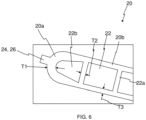
- at least one of the extreme end portions of the extruded tube 20 is formed with a rib 24 on at least one of the lateral walls thereof as illustrated in FIG. 6 .
- at least one of tank assembly 10 and extreme end portions of the extruded tube 20 is formed with tabs 26 to form crimping connection between the tank assembly 10 and extreme end portions of the extruded tube 20 as illustrated in FIG. 6 .
- the crimping tab 26 extends from extreme end portions of the extruded tube 20.
- the pair of panels 10a and 10b includes inwardly bended ends 12a and 12b that extend from tank assembly 10 towards the tube 20 received in the tank assembly 10 as illustrated in FIG. 7 .
- the bended ends 12a and 12b melt and fuse with the extruded tube 20 during welding to fill the gap at the triple point inherently formed at the interface between the extruded tube 20 and the pair of panels 10a and 10b.
- At least one of the extreme end portions of at least one of the end channels 22b is having outwardly facing lateral wall comparatively thicker than the channel walls 22a and the longitudinal walls 20b of the extruded tube 20.
Landscapes
- Engineering & Computer Science (AREA)
- Physics & Mathematics (AREA)
- Thermal Sciences (AREA)
- Mechanical Engineering (AREA)
- General Engineering & Computer Science (AREA)
- Manufacturing & Machinery (AREA)
- Chemical & Material Sciences (AREA)
- Chemical Kinetics & Catalysis (AREA)
- Electrochemistry (AREA)
- General Chemical & Material Sciences (AREA)
- Geometry (AREA)
- Secondary Cells (AREA)
Abstract
Description
- The present invention relates to a heat exchanger, particularly, to a battery cooler for cooling batteries in electric vehicle.
- Generally, a battery cooler is a heat exchanger that includes a tube and a tank assembly. The tube is an extruded micro-channel tube formed with multiple channels for flow of coolant there through. The tank assembly is formed by joining a pair of panels. The extruded tube, particularly extreme end portions of the extruded tube are received and joined to the respective tank assemblies. The portion of the tube between the end portions follow a wave pattern, so that when multiple tubes with respective tank assemblies are disposed adjacent to one another along a first direction in spaced apart configuration, battery-accommodating spaces for receiving the batteries to be cooled are formed between crests of adjacent tubes. The tank assembly receives pressurized fluid, particularly, coolant and either distributes the coolant to or collects the coolant from the tube. The connection between the extruded tube and the tank assembly is required to be secure and air tight to prevent any leakage of the coolant from the interface between the tube and the tank assembly. Generally, the tube is joined to the tank assembly by a joining process such as brazing. However, the brazing of the microchannel tube to the tank assembly is a problem. The inherent heating of the microchannel tube during the brazing process, is detrimental to the mechanical properties, particularly, the mechanical resistance of the microchannel tubes. Furthermore, the entire microchannel tube is unnecessarily heated in the brazing furnace wherein only the ends of the microchannel tube should be subjected to heating for brazing for securely connecting the ends of the microchannel tube to the tank. There are further disadvantages of subjecting the entire microchannel tube to brazing in brazing furnace, for example, there is wastage of energy and need for larger brazing furnaces when the entire microchannel tubes are subjected to the brazing in the brazing furnace. Further, the brazing process involves other problems such as CO2 emissions that renders the working environment hazardous for workers and causes harm to the environment. Further, brazing requires furnaces, jigs and fixtures and is uneconomical.
- Generally, the tank assembly and tube are welded by fillet joint, wherein melted material from the tank is fused with the tube for forming the connection. Also, a gap is created at the triple point inherently formed at the interface between extruded tube and the pair of panels at the lateral corners of the tank assembly. The gap is required to be filled and blocked to prevent coolant leakage between the tube and the tank assembly. However, the conventional joining processes such as fillet joint welding process and filler wire process fail to provide economic and convenient solution for filling the gap. Particularly, the filler wire process renders the joining process slow and is inconvenient. Such gap may lead to leakage of the coolant through the gap between the tube and the tank assembly, thereby causing loss of coolant and hot spots in the battery cooler due to insufficient coolant supply. The insufficient coolant flow through the tube due to leakage of coolant may cause inefficient cooling of the batteries. The inefficient cooling of the batteries will adversely impact efficiency and performance of the batteries and eventually lead to battery failure and reduced service life of the batteries due to battery over-heating. Furthermore, the thinner sections of the tube are prone to joining defects and damage when subject to fusion joining that could further aggravate the problems of leakages due to joining defects.
- According, there is a need for a heat exchanger, particularly, a battery cooler that involves a joining method that obviates the drawbacks of convention joining processes such as brazing for forming connection between the tube and the tank assembly. More specifically, there is a need for a heat exchanger that involves a joining method that is quick and efficient. Another object of the present invention is to provide a heat exchanger that ensures robust, secure and air tight connection between the tube and the tank assembly to prevent coolant leakage, thereby avoiding frequent refilling of the coolant. Further, there is need for a heat exchanger that exhibits improved efficiency and performance compared to conventional heat exchangers, thereby preventing battery failure due to overheating thereof accordingly reducing maintenance and improving service life of the batteries cooled thereby. Furthermore, there is a need for a heat exchanger that avoids welding defects.
- A heat exchanger is disclosed in accordance with an embodiment of the present invention. The heat exchanger includes a tank assembly and a tube. The tank assembly is formed by joining a pair of panels. The tube includes a plurality of channels. The tube is received and joined to the tank assembly. At least one of the extreme end portions of the tube is having at least one of the lateral walls comparatively thicker than longitudinal walls and channel walls of the tube.
- The longitudinal walls are extending along the width of the tube and the lateral walls are orthogonal to and connecting the longitudinal walls.
- Preferably, the tube is joined to the tank assembly by laser welding.
- Generally, the tube and the tank assembly are of aluminum alloy.
- Generally, the panels are formed by stamping and are having thickness in the range of 0.7 - 0.9 mm.
- Further, the longitudinal walls and the channel walls are having thickness in the range of 0.2 to 0.4 mm, while lateral walls of the extreme end portions of the tube is having thickness in the range of 0.5 to 0.6 mm.
- Particularly, thicker sections of the lateral wall of the tube is adapted to melt and fuse with tank assembly during welding and fill the gap at the triple point inherently formed at the interface between the tube and the pair of panels.
- In accordance with an embodiment of the present invention, at least one of the extreme end portions of the tube is formed with a rib on at least one of the lateral walls thereof.
- More specifically, both extreme end portions of the tube are having lateral walls comparatively thicker than the channel walls and longitudinal walls.
- In accordance with another embodiment of the present invention, at least one of tank assembly and extreme end portions of the tube is formed with tabs to form crimping connection between the tank assembly and extreme end portions of the tube. The crimped tabs melt and fuse during welding to fill the gap at the triple point inherently formed at the interface between tube and the pair of panels.
- In accordance with yet another embodiment of the present invention, the pair of panels includes inwardly bended ends that extend from tank assembly towards the tube received in the tank. The inwardly bended ends of the pair of panels melt and fuse during welding to fill the gap at the triple point inherently formed at the interface between tube and the pair of panels.
- Further, at least one of the extreme end portions of at least one of the end channels is having outwardly facing lateral wall that is comparatively thicker than the channel walls and longitudinal walls.
- Generally, the tube is either extruded tube or bended tube.
- Other characteristics, details and advantages of the invention can be inferred from the description of the invention hereunder. A more complete appreciation of the invention and many of the attendant advantages thereof will be readily obtained as the same becomes better understood by reference to the following detailed description when considered in connection with the accompanying figures, wherein:
-
FIG.1 illustrates a front view of a conventional heat exchanger, particularly, a battery cooler, also is illustrated a sectional view of the battery cooler along section line A-A'; -
FIG.2 illustrates an isometric view of a portion of a heat exchanger, particularly, a battery cooler in accordance with an embodiment of the present invention; -
FIG. 3 illustrates a front view of a heat exchanger, particularly, a battery cooler, also is illustrated a sectional view of the battery cooler along section line B-B'; -
FIG. 4 illustrates an enlarged view of a portion of a tube, particularly, an extruded tube of the battery cooler ofFIG. 2 depicting at least a portion of a lateral wall of the extruded tube being comparatively thicker than longitudinal walls and channel walls; -
FIG. 5 illustrates an isometric view of an end portion of the extruded tube ofFIG. 4 , also is illustrated an enlarged view of the end portion; -
FIG. 6 illustrates an enlarged view of an extruded tube of the battery cooler ofFIG. 2 depicting a rib or a crimping tab formed on at least a portion of a lateral wall of the extruded tube. -
FIG. 7 illustrates an enlarged view of a section of a battery cooler depicting at least a lateral wall of extruded tube being comparatively thicker and pair of panels forming the tank assembly includes inwardly bended ends. - It must be noted that the figures disclose the invention in a detailed enough way to be implemented, said figures helping to better define the invention if needs be. The invention should however not be limited to the embodiment disclosed in the description.
- Although, the present invention is explained with example of battery cooler, wherein the battery cooler includes a tank assembly and a tube, such as for example, an extruded tube, however, the present invention is applicable for any heat exchanger used in vehicular and non-vehicular environment, wherein it is required to configure secure and air tight connection between parts thereof, wherein at least one of the parts is made thicker by providing additional material for filling the gap at the triple point inherently formed at the interface between the parts to be joined by joining process. The tank assembly is formed by joining a pair of panels. The extruded tube includes a plurality of channels. The extruded tube is received and joined to the tank assembly by a quick and efficient joining process such as for example laser welding. At least one of the extreme end portions of the extruded tube is having at least one of the lateral walls comparatively thicker than longitudinal walls and channel walls of the extruded tube. The thicker sections of the lateral walls of the extruded tube are fused during the laser welding and fill the gap at the triple point inherently formed at the interface between extruded tube and the pair of panels. Such secure and air tight connection between the tube and the tank assembly renders the heat exchanger efficient and improves the reliability service life thereof.
- A conventional heat exchanger, for example, a
battery cooler 1 includes atube 2 and atank assembly 4. Thetube 2 is an extruded micro-channel tube formed with multiple channels for flow of coolant there through. The channels are defined bychannel walls 2a. Thetank assembly 4 is formed by joining a pair ofpanels extruded tube 2, particularly extreme end portions of the extrudedtube 2 are received and joined to therespective tank assemblies 4. Generally, thetank assembly 4 and thetube 2 are welded by fillet joint, wherein melted material from thetank 4 is melted and fused with thetube 2 for forming the connection. Also, a gap 6 is created at the triple point inherently formed at the interface betweenextruded tube 2 and the pair ofpanels tank assembly 4. The gap 6 is required to be filled and blocked to prevent coolant leakage between thetube 2 and thetank assembly 4. However, the conventional joining processes such as fillet joint welding process and filler wire process fail to provide economic and convenient solution for filling the gap 6. Particularly, the filler wire process renders the joining process slow and is inconvenient. Such gap 6 may lead to leakage of the coolant there through, thereby causing loss of coolant and hot spots in thebattery cooler 1 due to insufficient coolant supply. The insufficient coolant flow through thetube 2 due to leakage of coolant may cause inefficient cooling of the batteries. -
FIG. 2 illustrates an isometric view of aheat exchanger 100, particularly, a battery cooler, hereinafter referred to as battery cooler 100 in accordance with an embodiment of the present invention. Also is illustrated inFIG. 3 a sectional view of thebattery cooler 100 depicting relative position and interaction between the various components of thebattery cooler 100. Thebattery cooler 100 includes atank assembly 10 and a tube, such as for example an extrudedtube 20 and herein after referred to as extrudedtube 20. Although, the forthcoming descriptions is explained with example of extruded tube, however, the present invention is not limited to extruded tubes but also applicable to tubes of other configuration such as for example, tubes formed by bending. - The
tank assembly 10 is of aluminum alloy and is formed by joining a pair ofpanels panels panels tank assembly 10 includes a pair of lateral sides defined by thepanels panels tube 20 and the extrudedtube 20 is joined to thetank assembly 10 by laser welding. However, the present invention is not limited to any particular configuration of thetank assembly 10, thetank assembly 10 can be single piece component or can be configured by joining multiple components joined by laser welding that is quick and efficient. - The extruded
tube 20 is of aluminum alloy. The extrudedtube 20 includes a plurality of channels defined bychannel walls 22. The extrudedtube 20 is received and joined to thetank assembly 10 by laser welding. Particularly extreme end portions of the extrudedtube 20 are received and joined to thetank assemblies 10. More specifically, the micro-channels follow either an I-pattern or U-pattern to configure either an I-flow or U-flow of the coolant. In case the I-flow configuration, opposite ends of the extruded tube are open and are received inseparate tank assemblies 10. In case of U-flow configuration, open ends of the microchannel tubes are distributed in separate portions of asingle tank assembly 10 defined a baffle disposed inside thesingle tank assembly 10 and dividing the interior of the tank assembly into different portions. The portion of thetube 20 between the end portions follow a wave pattern, so that whentubes 20 are disposed adjacent to one another along a first direction in spaced apart configuration, battery-accommodating spaces for receiving the batteries to be cooled are formed between crests ofadjacent tubes 20. - At least one of the extreme end portions of the extruded
tube 20 is having at least one oflateral walls 20a thereof comparatively thicker thanlongitudinal walls 20b andchannel walls 22a of the extrudedtube 20.FIG. 5 illustrates an isometric view of an end portion of the extrudedtube 20. Thelongitudinal walls 20b are extending along the width of thetube 20 and the lateral walls are orthogonal to and connecting thelongitudinal walls 20b. More specifically, both extreme end portions of the extrudedtube 20 are having lateral walls comparatively thicker than thechannel walls 22a and thelongitudinal walls 20b. Generally, the extrudedtube 20 is formed by extrusion and thelongitudinal walls 20b and thechannel walls 22a are having thickness in the range of 0.2 to 0.4 mm, while thelateral walls 20a of the extreme end portions of extruded tube is having thickness in the range of 0.5 to 0.6 mm. Particularly, thicker sections of thelateral walls 20a of the extrudedtube 20 is fused during the laser welding and fill the gap at the triple point inherently formed at the interface betweenextruded tube 20 and the pair ofpanels - In conventional heat exchangers, a gap 6 is created at the triple point inherently formed at the interface between extruded tube and the pair of panels. The gap is required to be filled and blocked to prevent coolant leakage between the
tube 2 and thetank assembly 4. However, the conventional joining processes such as fillet joint welding process and filler wire process fail to provide economic and convenient solution for filling the gap. Particularly, the filler wire process renders the joining process slow and is slow and inconvenient. The coolant leakage through the gap causes loss of coolant and hot spots in the battery cooler due to insufficient coolant supply. The insufficient coolant flow through thetube 2 due to leakage of coolant may cause inefficient cooling of the batteries. The inefficient cooling of the batteries will adversely impact efficiency and performance of the batteries and eventually lead to battery failure and reduced service life of the batteries due to battery over-heating. Additional material may be provided on extreme end portions of thelateral walls 20a of the extrudedtube 20 to fill the gap at the triple point inherently formed at the interface betweenextruded tube 20 and the pair ofpanels tank assembly 10 and the extrudedtube 20. - The present invention suggests providing additional material on extreme end portions of the
lateral walls 20a of the extrudedtube 20 in other different ways. In accordance with an embodiment of the present invention, at least one of the extreme end portions of the extrudedtube 20 is formed with a rib 24 on at least one of the lateral walls thereof as illustrated inFIG. 6 . In accordance with another embodiment of the present invention, at least one oftank assembly 10 and extreme end portions of the extrudedtube 20 is formed with tabs 26 to form crimping connection between thetank assembly 10 and extreme end portions of the extrudedtube 20 as illustrated inFIG. 6 . Preferably, the crimping tab 26 extends from extreme end portions of the extrudedtube 20. The crimped tabs 26 melt and fuse with thetank assembly 10 during welding to fill the gap at the triple point inherently formed at the interface between theextruded tube 20 and the pair ofpanels panels tank assembly 10 towards thetube 20 received in thetank assembly 10 as illustrated inFIG. 7 . The bended ends 12a and 12b melt and fuse with the extrudedtube 20 during welding to fill the gap at the triple point inherently formed at the interface between theextruded tube 20 and the pair ofpanels - Further, at least one of the extreme end portions of at least one of the
end channels 22b is having outwardly facing lateral wall comparatively thicker than thechannel walls 22a and thelongitudinal walls 20b of the extrudedtube 20. - In any case, the invention cannot and should not be limited to the embodiments specifically described in this document, as other embodiments might exist. The invention shall spread to any equivalent means and any technically operating combination of means.
Claims (11)
- A heat exchanger (100) comprising:• a tank assembly (10) formed by joining a pair of panels (10a) and (10b);• a tube (20) comprising a plurality of channels (22) and is adapted to be received and joined to the tank assembly (10),
characterized in that at least one of the extreme end portions of the tube (20) is having at least one of lateral walls (20a) comparatively thicker than longitudinal walls (20b) and channel walls (22a) of the tube (20). - The heat exchanger (100) as claimed in the previous claim, wherein the tube (20) is joined to the tank assembly (10) by laser welding.
- The heat exchanger (100) as claimed in any of the preceding claims, wherein the panels (10a) and (10b) are formed by stamping and are having thickness in the range of 0.7 - 0.9 mm.
- The heat exchanger (100) as claimed in any of the preceding claims, wherein the longitudinal walls (20b) and the channel walls (22a) are having thickness in the range of 0.2 to 0.4 mm, while the lateral walls (20a) of the extreme end portions of the tube (20) is having thickness in the range of 0.5 to 0.6 mm.
- The heat exchanger (100) as claimed in any of the preceding claims, wherein thicker sections of the lateral walls (20a) of the tube (20) is adapted to melt and fuse with the tank assembly (10) during welding and fill the gap at the triple point inherently formed at the interface between the tube (20) and the pair of panels (10a, 10b).
- The heat exchanger (100) as claimed in any of the preceding claims, wherein at least one of the extreme end portions of the tube (20) is formed with a rib on at least one of the lateral walls (20a) thereof.
- The heat exchanger (100) as claimed in any of the preceding claims, wherein both extreme end portions of the tube (20) are having lateral walls comparatively thicker than the channel walls (22a) and the longitudinal walls (20b).
- The heat exchanger (100) as claimed in any of the preceding claims, wherein at least one of the tank assembly (10) and extreme end portions of the tube (20) is formed with tabs to form crimping connection between the tank assembly (10) and extreme end portions of the tube (20), the crimped tabs are adapted to melt and fuse during welding to fill the gap at the triple point inherently formed at the interface between the tube (20) and the pair of panels (10a) and (10b).
- The heat exchanger (100) as claimed in any of the preceding claims, wherein the pair of panels (10a) and (10b) comprises inwardly bended ends that extend from tank assembly (10) towards the tube (20) received in the tank assembly (10) and is adapted to melt and fuse during welding to fill the gap at the triple point inherently formed at the interface between the tube (20) and the pair of panels (10a) and (10b).
- The heat exchanger (100) as claimed in any of the preceding claims, wherein at least one of the extreme end portions of at least one of the end channels (22b) is having outwardly facing lateral wall that is comparatively thicker than the channel walls (22a) and the longitudinal walls (20b).
- The heat exchanger (100) as claimed in any of the preceding claims, wherein the tube (20) is either extruded tube or bended tube.
Priority Applications (1)
| Application Number | Priority Date | Filing Date | Title |
|---|---|---|---|
| EP23164828.8A EP4438988B1 (en) | 2023-03-28 | 2023-03-28 | The present invention relates to a heat exchanger, particularly, to a battery cooler for cooling batteries in electric vehicle |
Applications Claiming Priority (1)
| Application Number | Priority Date | Filing Date | Title |
|---|---|---|---|
| EP23164828.8A EP4438988B1 (en) | 2023-03-28 | 2023-03-28 | The present invention relates to a heat exchanger, particularly, to a battery cooler for cooling batteries in electric vehicle |
Publications (2)
| Publication Number | Publication Date |
|---|---|
| EP4438988A1 true EP4438988A1 (en) | 2024-10-02 |
| EP4438988B1 EP4438988B1 (en) | 2025-10-01 |
Family
ID=85779032
Family Applications (1)
| Application Number | Title | Priority Date | Filing Date |
|---|---|---|---|
| EP23164828.8A Active EP4438988B1 (en) | 2023-03-28 | 2023-03-28 | The present invention relates to a heat exchanger, particularly, to a battery cooler for cooling batteries in electric vehicle |
Country Status (1)
| Country | Link |
|---|---|
| EP (1) | EP4438988B1 (en) |
Citations (4)
| Publication number | Priority date | Publication date | Assignee | Title |
|---|---|---|---|---|
| US20140090823A1 (en) * | 2012-09-28 | 2014-04-03 | Behr Gmbh & Co. Kg | Heat exchanger |
| EP3447432B1 (en) * | 2017-08-23 | 2021-08-11 | Commissariat à l'énergie atomique et aux énergies alternatives | Heat exchange plate member having microchannels comprising a plate-edge assembly element |
| WO2022233526A1 (en) * | 2021-05-05 | 2022-11-10 | Bayerische Motoren Werke Aktiengesellschaft | Plug-in connection element for a cooler of a high-voltage accumulator |
| FR3125636A1 (en) * | 2021-07-26 | 2023-01-27 | Valeo Systemes Thermiques | Thermal regulation device for cooling electrical energy storage devices. |
-
2023
- 2023-03-28 EP EP23164828.8A patent/EP4438988B1/en active Active
Patent Citations (4)
| Publication number | Priority date | Publication date | Assignee | Title |
|---|---|---|---|---|
| US20140090823A1 (en) * | 2012-09-28 | 2014-04-03 | Behr Gmbh & Co. Kg | Heat exchanger |
| EP3447432B1 (en) * | 2017-08-23 | 2021-08-11 | Commissariat à l'énergie atomique et aux énergies alternatives | Heat exchange plate member having microchannels comprising a plate-edge assembly element |
| WO2022233526A1 (en) * | 2021-05-05 | 2022-11-10 | Bayerische Motoren Werke Aktiengesellschaft | Plug-in connection element for a cooler of a high-voltage accumulator |
| FR3125636A1 (en) * | 2021-07-26 | 2023-01-27 | Valeo Systemes Thermiques | Thermal regulation device for cooling electrical energy storage devices. |
Also Published As
| Publication number | Publication date |
|---|---|
| EP4438988B1 (en) | 2025-10-01 |
Similar Documents
| Publication | Publication Date | Title |
|---|---|---|
| US6938675B2 (en) | Heat exchanger | |
| US8037930B2 (en) | Heat exchanger | |
| AU684091B2 (en) | Heat exchanger and method for manufacturing thereof | |
| US5704415A (en) | Winding small tube apparatus and manufacturing method thereof | |
| US11007592B2 (en) | Heat exchanger and method for producing same | |
| US20070181291A1 (en) | Heat exchanger and method of manufacturing the same | |
| MXPA05005637A (en) | Thermal cycling resistant tube to header joint for heat exchangers. | |
| CN107110619A (en) | Tube plate, header and heat exchanger for heat exchanger | |
| JP3829494B2 (en) | Heat exchanger | |
| EP3644004B1 (en) | Heat exchanger | |
| JP2016200312A (en) | HEAT EXCHANGER AND HEAT EXCHANGER MANUFACTURING METHOD | |
| EP4438988B1 (en) | The present invention relates to a heat exchanger, particularly, to a battery cooler for cooling batteries in electric vehicle | |
| KR102038550B1 (en) | Heat exchanger | |
| US20200111725A1 (en) | Stacked heat exchanger and method for producing stacked heat exchanger | |
| EP1068033B1 (en) | Process for making a fluid-tight connection betweeen a tube and a plate-shaped part | |
| CN111133269B (en) | pipe connection | |
| KR200432601Y1 (en) | Heat exchanger header pipe | |
| JP3818223B2 (en) | tank | |
| JP2025093460A (en) | Heat exchanger and method for manufacturing the same | |
| EP3690372A1 (en) | Heat exchanger for motor vehicle | |
| EP4474750A1 (en) | A heat exchanger | |
| JP3126509B2 (en) | Manufacturing method of aluminum heat exchanger | |
| EP4560245B1 (en) | A heat exchanger | |
| KR100740699B1 (en) | Heat exchanger header pipe | |
| KR101578305B1 (en) | Manufacturing method of heat exchanger |
Legal Events
| Date | Code | Title | Description |
|---|---|---|---|
| PUAI | Public reference made under article 153(3) epc to a published international application that has entered the european phase |
Free format text: ORIGINAL CODE: 0009012 |
|
| STAA | Information on the status of an ep patent application or granted ep patent |
Free format text: STATUS: THE APPLICATION HAS BEEN PUBLISHED |
|
| AK | Designated contracting states |
Kind code of ref document: A1 Designated state(s): AL AT BE BG CH CY CZ DE DK EE ES FI FR GB GR HR HU IE IS IT LI LT LU LV MC ME MK MT NL NO PL PT RO RS SE SI SK SM TR |
|
| STAA | Information on the status of an ep patent application or granted ep patent |
Free format text: STATUS: REQUEST FOR EXAMINATION WAS MADE |
|
| GRAP | Despatch of communication of intention to grant a patent |
Free format text: ORIGINAL CODE: EPIDOSNIGR1 |
|
| STAA | Information on the status of an ep patent application or granted ep patent |
Free format text: STATUS: GRANT OF PATENT IS INTENDED |
|
| 17P | Request for examination filed |
Effective date: 20250325 |
|
| RIC1 | Information provided on ipc code assigned before grant |
Ipc: F28F 1/00 20060101AFI20250403BHEP |
|
| INTG | Intention to grant announced |
Effective date: 20250411 |
|
| GRAS | Grant fee paid |
Free format text: ORIGINAL CODE: EPIDOSNIGR3 |
|
| GRAA | (expected) grant |
Free format text: ORIGINAL CODE: 0009210 |
|
| STAA | Information on the status of an ep patent application or granted ep patent |
Free format text: STATUS: THE PATENT HAS BEEN GRANTED |
|
| AK | Designated contracting states |
Kind code of ref document: B1 Designated state(s): AL AT BE BG CH CY CZ DE DK EE ES FI FR GB GR HR HU IE IS IT LI LT LU LV MC ME MK MT NL NO PL PT RO RS SE SI SK SM TR |
|
| REG | Reference to a national code |
Ref country code: GB Ref legal event code: FG4D Ref country code: CH Ref legal event code: F10 Free format text: ST27 STATUS EVENT CODE: U-0-0-F10-F00 (AS PROVIDED BY THE NATIONAL OFFICE) Effective date: 20251001 |
|
| REG | Reference to a national code |
Ref country code: IE Ref legal event code: FG4D |
|
| REG | Reference to a national code |
Ref country code: DE Ref legal event code: R096 Ref document number: 602023007032 Country of ref document: DE |
|
| REG | Reference to a national code |
Ref country code: NL Ref legal event code: MP Effective date: 20251001 |
|
| REG | Reference to a national code |
Ref country code: CH Ref legal event code: W10 Free format text: ST27 STATUS EVENT CODE: U-0-0-W10-W00 (AS PROVIDED BY THE NATIONAL OFFICE) Effective date: 20260218 |
|
| REG | Reference to a national code |
Ref country code: AT Ref legal event code: MK05 Ref document number: 1842850 Country of ref document: AT Kind code of ref document: T Effective date: 20251001 |
|
| PG25 | Lapsed in a contracting state [announced via postgrant information from national office to epo] |
Ref country code: NL Free format text: LAPSE BECAUSE OF FAILURE TO SUBMIT A TRANSLATION OF THE DESCRIPTION OR TO PAY THE FEE WITHIN THE PRESCRIBED TIME-LIMIT Effective date: 20251001 |
|
| RAP2 | Party data changed (patent owner data changed or rights of a patent transferred) |
Owner name: VALEO ELECTRIFICATION |
|
| PG25 | Lapsed in a contracting state [announced via postgrant information from national office to epo] |
Ref country code: ES Free format text: LAPSE BECAUSE OF FAILURE TO SUBMIT A TRANSLATION OF THE DESCRIPTION OR TO PAY THE FEE WITHIN THE PRESCRIBED TIME-LIMIT Effective date: 20251001 |
|
| REG | Reference to a national code |
Ref country code: LT Ref legal event code: MG9D |
|
| PG25 | Lapsed in a contracting state [announced via postgrant information from national office to epo] |
Ref country code: NO Free format text: LAPSE BECAUSE OF FAILURE TO SUBMIT A TRANSLATION OF THE DESCRIPTION OR TO PAY THE FEE WITHIN THE PRESCRIBED TIME-LIMIT Effective date: 20260101 |
|
| PGFP | Annual fee paid to national office [announced via postgrant information from national office to epo] |
Ref country code: DE Payment date: 20260313 Year of fee payment: 4 |
|
| PG25 | Lapsed in a contracting state [announced via postgrant information from national office to epo] |
Ref country code: HR Free format text: LAPSE BECAUSE OF FAILURE TO SUBMIT A TRANSLATION OF THE DESCRIPTION OR TO PAY THE FEE WITHIN THE PRESCRIBED TIME-LIMIT Effective date: 20251001 Ref country code: FI Free format text: LAPSE BECAUSE OF FAILURE TO SUBMIT A TRANSLATION OF THE DESCRIPTION OR TO PAY THE FEE WITHIN THE PRESCRIBED TIME-LIMIT Effective date: 20251001 Ref country code: AT Free format text: LAPSE BECAUSE OF FAILURE TO SUBMIT A TRANSLATION OF THE DESCRIPTION OR TO PAY THE FEE WITHIN THE PRESCRIBED TIME-LIMIT Effective date: 20251001 |
|
| PG25 | Lapsed in a contracting state [announced via postgrant information from national office to epo] |
Ref country code: RS Free format text: LAPSE BECAUSE OF FAILURE TO SUBMIT A TRANSLATION OF THE DESCRIPTION OR TO PAY THE FEE WITHIN THE PRESCRIBED TIME-LIMIT Effective date: 20260101 |
|
| PG25 | Lapsed in a contracting state [announced via postgrant information from national office to epo] |
Ref country code: IS Free format text: LAPSE BECAUSE OF FAILURE TO SUBMIT A TRANSLATION OF THE DESCRIPTION OR TO PAY THE FEE WITHIN THE PRESCRIBED TIME-LIMIT Effective date: 20260201 |
|
| PG25 | Lapsed in a contracting state [announced via postgrant information from national office to epo] |
Ref country code: CZ Free format text: LAPSE BECAUSE OF FAILURE TO SUBMIT A TRANSLATION OF THE DESCRIPTION OR TO PAY THE FEE WITHIN THE PRESCRIBED TIME-LIMIT Effective date: 20251001 Ref country code: PT Free format text: LAPSE BECAUSE OF FAILURE TO SUBMIT A TRANSLATION OF THE DESCRIPTION OR TO PAY THE FEE WITHIN THE PRESCRIBED TIME-LIMIT Effective date: 20260202 |
|
| PG25 | Lapsed in a contracting state [announced via postgrant information from national office to epo] |
Ref country code: PL Free format text: LAPSE BECAUSE OF FAILURE TO SUBMIT A TRANSLATION OF THE DESCRIPTION OR TO PAY THE FEE WITHIN THE PRESCRIBED TIME-LIMIT Effective date: 20251001 |
|
| PG25 | Lapsed in a contracting state [announced via postgrant information from national office to epo] |
Ref country code: LV Free format text: LAPSE BECAUSE OF FAILURE TO SUBMIT A TRANSLATION OF THE DESCRIPTION OR TO PAY THE FEE WITHIN THE PRESCRIBED TIME-LIMIT Effective date: 20251001 |
|
| PG25 | Lapsed in a contracting state [announced via postgrant information from national office to epo] |
Ref country code: BG Free format text: LAPSE BECAUSE OF FAILURE TO SUBMIT A TRANSLATION OF THE DESCRIPTION OR TO PAY THE FEE WITHIN THE PRESCRIBED TIME-LIMIT Effective date: 20251001 |