EP4438969A1 - Heat exchange unit and refrigeration cycle device - Google Patents
Heat exchange unit and refrigeration cycle device Download PDFInfo
- Publication number
- EP4438969A1 EP4438969A1 EP22933465.1A EP22933465A EP4438969A1 EP 4438969 A1 EP4438969 A1 EP 4438969A1 EP 22933465 A EP22933465 A EP 22933465A EP 4438969 A1 EP4438969 A1 EP 4438969A1
- Authority
- EP
- European Patent Office
- Prior art keywords
- wall
- room
- hole
- holes
- wire
- Prior art date
- Legal status (The legal status is an assumption and is not a legal conclusion. Google has not performed a legal analysis and makes no representation as to the accuracy of the status listed.)
- Granted
Links
Images




Classifications
-
- F—MECHANICAL ENGINEERING; LIGHTING; HEATING; WEAPONS; BLASTING
- F25—REFRIGERATION OR COOLING; COMBINED HEATING AND REFRIGERATION SYSTEMS; HEAT PUMP SYSTEMS; MANUFACTURE OR STORAGE OF ICE; LIQUEFACTION SOLIDIFICATION OF GASES
- F25B—REFRIGERATION MACHINES, PLANTS OR SYSTEMS; COMBINED HEATING AND REFRIGERATION SYSTEMS; HEAT PUMP SYSTEMS
- F25B49/00—Arrangement or mounting of control or safety devices
- F25B49/02—Arrangement or mounting of control or safety devices for compression type machines, plants or systems
-
- F—MECHANICAL ENGINEERING; LIGHTING; HEATING; WEAPONS; BLASTING
- F25—REFRIGERATION OR COOLING; COMBINED HEATING AND REFRIGERATION SYSTEMS; HEAT PUMP SYSTEMS; MANUFACTURE OR STORAGE OF ICE; LIQUEFACTION SOLIDIFICATION OF GASES
- F25D—REFRIGERATORS; COLD ROOMS; ICE-BOXES; COOLING OR FREEZING APPARATUS NOT OTHERWISE PROVIDED FOR
- F25D17/00—Arrangements for circulating cooling fluids; Arrangements for circulating gas, e.g. air, within refrigerated spaces
- F25D17/04—Arrangements for circulating cooling fluids; Arrangements for circulating gas, e.g. air, within refrigerated spaces for circulating air, e.g. by convection
- F25D17/06—Arrangements for circulating cooling fluids; Arrangements for circulating gas, e.g. air, within refrigerated spaces for circulating air, e.g. by convection by forced circulation
- F25D17/067—Evaporator fan units
-
- F—MECHANICAL ENGINEERING; LIGHTING; HEATING; WEAPONS; BLASTING
- F24—HEATING; RANGES; VENTILATING
- F24F—AIR-CONDITIONING; AIR-HUMIDIFICATION; VENTILATION; USE OF AIR CURRENTS FOR SCREENING
- F24F1/00—Room units for air-conditioning, e.g. separate or self-contained units or units receiving primary air from a central station
- F24F1/0007—Indoor units, e.g. fan coil units
- F24F1/0068—Indoor units, e.g. fan coil units characterised by the arrangement of refrigerant piping outside the heat exchanger within the unit casing
-
- F—MECHANICAL ENGINEERING; LIGHTING; HEATING; WEAPONS; BLASTING
- F24—HEATING; RANGES; VENTILATING
- F24F—AIR-CONDITIONING; AIR-HUMIDIFICATION; VENTILATION; USE OF AIR CURRENTS FOR SCREENING
- F24F1/00—Room units for air-conditioning, e.g. separate or self-contained units or units receiving primary air from a central station
- F24F1/06—Separate outdoor units, e.g. outdoor unit to be linked to a separate room comprising a compressor and a heat exchanger
- F24F1/14—Heat exchangers specially adapted for separate outdoor units
- F24F1/16—Arrangement or mounting thereof
-
- F—MECHANICAL ENGINEERING; LIGHTING; HEATING; WEAPONS; BLASTING
- F24—HEATING; RANGES; VENTILATING
- F24F—AIR-CONDITIONING; AIR-HUMIDIFICATION; VENTILATION; USE OF AIR CURRENTS FOR SCREENING
- F24F1/00—Room units for air-conditioning, e.g. separate or self-contained units or units receiving primary air from a central station
- F24F1/06—Separate outdoor units, e.g. outdoor unit to be linked to a separate room comprising a compressor and a heat exchanger
- F24F1/20—Electric components for separate outdoor units
-
- F—MECHANICAL ENGINEERING; LIGHTING; HEATING; WEAPONS; BLASTING
- F24—HEATING; RANGES; VENTILATING
- F24F—AIR-CONDITIONING; AIR-HUMIDIFICATION; VENTILATION; USE OF AIR CURRENTS FOR SCREENING
- F24F1/00—Room units for air-conditioning, e.g. separate or self-contained units or units receiving primary air from a central station
- F24F1/06—Separate outdoor units, e.g. outdoor unit to be linked to a separate room comprising a compressor and a heat exchanger
- F24F1/20—Electric components for separate outdoor units
- F24F1/24—Cooling of electric components
-
- F—MECHANICAL ENGINEERING; LIGHTING; HEATING; WEAPONS; BLASTING
- F24—HEATING; RANGES; VENTILATING
- F24F—AIR-CONDITIONING; AIR-HUMIDIFICATION; VENTILATION; USE OF AIR CURRENTS FOR SCREENING
- F24F1/00—Room units for air-conditioning, e.g. separate or self-contained units or units receiving primary air from a central station
- F24F1/06—Separate outdoor units, e.g. outdoor unit to be linked to a separate room comprising a compressor and a heat exchanger
- F24F1/46—Component arrangements in separate outdoor units
-
- F—MECHANICAL ENGINEERING; LIGHTING; HEATING; WEAPONS; BLASTING
- F25—REFRIGERATION OR COOLING; COMBINED HEATING AND REFRIGERATION SYSTEMS; HEAT PUMP SYSTEMS; MANUFACTURE OR STORAGE OF ICE; LIQUEFACTION SOLIDIFICATION OF GASES
- F25B—REFRIGERATION MACHINES, PLANTS OR SYSTEMS; COMBINED HEATING AND REFRIGERATION SYSTEMS; HEAT PUMP SYSTEMS
- F25B39/00—Evaporators; Condensers
- F25B39/02—Evaporators
Definitions
- the present disclosure relates to a heat exchange unit and refrigeration cycle device.
- Patent Document 1 An air conditioner having an electric components box mounted thereon is known.
- Patent Document 1 Japanese Unexamined Application No. 2015-59735 , First Publication
- the object of providing such shutter plate is to suppress a refrigerant that has leaked from penetrating to an inside of an electric components box.
- the aforementioned shutter plate however, there are cases where suppressing the refrigerant that has leaked from penetrating to the inside of the electric components box is not sufficient.
- the present disclosure has been made in order to address the problem above, and one object is to provide a heat exchange unit having a structure that suitably suppresses penetration of refrigerant to an inside of an electric components box, and to provide a refrigeration cycle device that includes such heat exchange unit.
- a heat exchange unit of a refrigeration cycle device includes: a housing having a first room and a second room that are portioned from one another by a partition member; a heat exchanger that is disposed on an inside of the first room; a blower that is disposed on the inside of the first room; a refrigerant pipe that is disposed on an inside of the second room and that is connected to the heat exchanger, and a control unit that is disposed so as to straddle between the inside of the first room and the inside of the second room.
- the first room and the second room are adjacently disposed in a first direction that intersects a vertical direction.
- the control unit has an electric components box disposed on the inside of the first room, a wire that extends to the inside of the second room after being pulled out from a lead-out hole, a first wall located between the electric components box and the inside of the second room, and a second wall located between the first wall and the inside of the second room.
- a space is formed between the first wall and the second wall.
- the wire extends from the inside of the first room to the inside of the second room, via the space, passing through a second through hole out of second through holes that are formed on the second wall.
- a surface out of the first wall that faces the space faces the second through hole out of second through holes that are formed on the second wall in the first direction.
- An end of the top side out of the space in the vertical direction, and both ends in a second direction that intersects with the vertical direction and is orthogonal to the first direction out of the space, are closed off.
- the space has an opening that opens to the bottom side in the vertical direction, and the opening opens to the inside of the first room.
- a refrigeration cycle device includes an outdoor unit, and an indoor unit, wherein the outdoor unit or the indoor unit may be the heat exchange unit mentioned above.
- an electric components box of a refrigeration cycle device it is possible to suitably suppress penetration of refrigerant to an inside of the electric components box.
- the drawings show an X axis, a Y axis, and a Z axis where appropriate.
- the X axis shows a side out of sides of a horizontal direction.
- the Y axis shows another side out of sides of the horizontal direction.
- the Z axis shows a vertical direction.
- a horizontal direction along the X axis is referred to as a "front-rear direction X”
- a horizontal direction along the Y axis is referred to as a "left-right direction Y”.
- a vertical direction is referred to as a "vertical direction Z”.
- the front-rear direction X, the left-right direction Y, and the vertical direction Z are mutually orthogonal directions.
- a side out of sides of the vertical direction Z in which an arrow of the Z axis faces is a top side (+Z side).
- the other side out of sides of the vertical direction Z which faces an opposite side the arrow of the Z axis faces is a bottom side (-Z side).
- a side out of sides of the front-rear direction X in which an arrow of the X axis faces is a front side (+X side).
- a side out of sides of the front-rear direction X which faces an opposite side the arrow of the X axis faces is a rear side (-X side).
- the left-right direction Y in the embodiment below, is the left-right direction Y in a case where an outdoor unit 10 is viewed from the front side (+X side).
- a side out of sides of the left-right direction Y in which an arrow of the Y axis faces is a right side (+Y side).
- a side out of sides in the left-right direction Y which faces an opposite side the arrow of the Y axis faces is a left side (-Y side).
- a direction where the left-right direction Y intersects with the vertical direction Z is referred to as a "first direction”.
- the front-rear direction X corresponds to a "second direction" which intersects the vertical direction Z, and is orthogonal to the first direction.
- FIG. 1 is a schematic view that shows an outline configuration of a refrigeration cycle device 100 in the embodiment.
- the refrigeration cycle device 100 is a device that uses a refrigeration cycle in which a refrigerant 19 is circulated.
- the refrigeration cycle device 100 in the embodiment is an air conditioner.
- the refrigeration cycle device 100 includes the outdoor unit 10, an indoor unit 20, and a circulation path 18.
- the outdoor unit 10 is disposed outdoors.
- the indoor unit 20 is disposed indoors.
- the outdoor unit 10 and the indoor unit 20 are connected by the circulation path 18 that circulates a refrigerant 19.
- the outdoor unit 10 and the indoor unit 20 are heat exchange units that conduct heat exchange with air.
- a refrigerant such as a fluorine based refrigerant with a low global warming potential (GWP: Global Warming Potential), or a hydrocarbon based refrigerant or the like may be mentioned as examples of the refrigerant 19.
- GWP Global Warming Potential
- a density of the refrigerant 19 in a gaseous state is larger than a density of air.
- the fluorine based refrigerant with a low global warming potential is for example, HFC32.
- An example of the hydrocarbon based refrigerant is R290 (propane). Both the fluorine based refrigerant and the hydrocarbon based refrigerant are flammable refrigerants.
- the outdoor unit 10 includes a housing 11, a compressor 12, a heat exchanger 13, a flow adjustment valve 14, a blower 15, a four-way valve 16, a refrigerant pipe 18a, and a control unit 30.
- the compressor 12, the heat exchanger 13, the flow adjustment valve 14, the blower 15, the four-way valve 16, the refrigerant pipe 18a and the control unit 30 are housed on an inside of the housing 11.
- the four-way valve 16 is provided on a part that is connected to a discharge side of the compressor 12. By exchanging a portion of the circulation pathway 18, it is possible for the four-way valve 16 to reverse a direction of flow of the refrigerant 19 within the circulation pathway 18.
- the path connected by the four-way valve 16 is the path of the four-way valve 16 that is shown by solid lines in FIG. 1
- the refrigerant 19 within the circulation pathway 18 flows in the direction shown by the solid line arrow in FIG. 1 .
- the path connected by the four-way valve 16 is the path of the four-way valve 16 that is shown by dashed lines in FIG. 1
- the refrigerant 19 flows within the circulation pathway 18 in the direction shown by the dashed line arrow in FIG. 1 .
- the refrigerant pipe 18a is a pipe that configures a portion of the circulation pathway 18.
- the refrigerant pipe 18a is connected to a pipe that extends from the indoor unit 20.
- a plurality of refrigerant pipes 18a are provided on an inside of the housing 11 of the outdoor unit 10.
- the indoor unit 20 includes a housing 21, a heat exchanger 22, a blower 23, and a controller 24.
- the housing 21 houses the heat exchanger 22, the blower 23, and the controller 24 on an inside thereof. It is possible for the indoor unit 20 to have a cooling operation where the air of the room the indoor unit 20 is disposed in is cooled, and to have a heating operation where the air of the room the indoor unit 20 is disposed in is heated.
- the refrigerant 19 that flows within the circulation pathway 18 flows in the direction shown by solid lines in FIG. 1 .
- the refrigerant 19 that flows within the circulation pathway 18 circulates so as to return to the compressor 12 after passing through the compressor 12, the heat exchanger 13 of the outdoor unit 10, the flow adjustment valve 14, and the heat exchanger 22 of the indoor unit 20 in such an order.
- the heat exchanger 13 of the outdoor unit 10 functions as a condenser
- the heat exchanger 22 of the indoor unit 20 functions as an evaporator.
- the refrigerant 19 that flows within the circulation pathway 18 flows in the direction shown by dashed lines in FIG. 1 .
- the refrigerant 19 that flows within the circulation pathway 18 circulates so as to return to the compressor 12 after passing through the compressor 12, the heat exchanger 22 of the indoor unit 20, the flow adjustment valve 14, and the heat exchanger 13 on an inside of the outdoor unit 10 in such an order.
- the heat exchanger 13 of the outdoor unit 10 functions as the evaporator
- the heat exchanger 22 on an inside of the indoor unit 20 functions as the condenser.
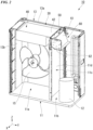
- FIG. 2 is a perspective view that shows a portion of the outdoor unit 10.
- FIG. 3 is a partial cross-sectional view that shows a portion of the outdoor unit 10.
- the housing 11 has a blower room 11a and a mechanical room 11b that are partitioned from one another by a partition member 11c.
- the blower room 11a corresponds to a "first room”
- the mechanical room 11b corresponds to a "second room”.
- the partition member 11c extends in the vertical direction Z.
- the partition member 11c has a partition plate 11d that extends in the vertical direction Z, and a bend 11e that bends to the right side from a top end of the partition plate 11d.
- the partition plate 11d is a semi-rectangular plate surface that faces the left-right direction Y.
- the bend 11e is a plate surface that faces the vertical direction Z.
- the bend 11e is provided on an entirety of the top end of the partition plate 11d in the front-rear direction X.
- a top end of the partition member 11c is separately disposed to the bottom side from a ceiling surface panel 11f of the housing 11.
- the ceiling surface panel 11f is a wall portion located on the top side out of wall portions that configure the housing 11.
- the top end of the partition member 11c in the present embodiment is the bend 11e.
- the blower room 11a and the mechanical room 11b are adjacently disposed in the left-right direction Y.
- a dimension of the blower room 11a in the left-right direction Y is larger than a dimension of the mechanical room 11b in the left-right direction Y.
- the blower room 11a is located on the left side of the mechanical room 11b.
- a heat exchanger 13 and the blower 15 are disposed on an inside of the blower room 11a.
- the heat exchanger 13 in the present embodiment, as seen from the vertical direction Z, is approximately L shaped.
- the heat exchanger 13 has a first portion 13a that extends in the left-right direction Y as seen from the vertical direction Z, and a second portion 13b that extends to the front side (+X side) from an end on the left side of the first portion 13a.
- the first portion 13a is disposed on a rear end of the inside of the blower room 11a.
- a left end of the first portion 13a is exposed to an inside of the mechanical room 11b.
- the circulation pathway 18 which is disposed on the inside of the mechanical room 11b is connected to a right end of the first portion 13a. Accordingly, the refrigerant pipe 18a is connected to the heat exchanger 13.
- the second portion 13b is disposed on a left end of an inside of the blower room 11a.
- the blower 15 is located on a front side of the first portion 13a in the heat exchanger 13, and a right side of the second portion 13b in the heat exchanger 13, on the inside of the blower room 11a.
- the air is taken into the blower room 11a from an intake port not shown on the drawings, that is provided on a wall portion on the rear side (-X side) of the blower room 11a.
- the air that is taken into the blower room 11a passes through the heat exchanger 13, and is discharged to an outside of the housing 11 from an exhaust port not shown on the drawings, that is provided on a wall portion on the front side (+X side) of the blower room 11a.
- the blower 15 sends the air to the heat exchanger 13.
- the compressor 12 is disposed on the inside of the mechanical room 11b.
- the compressor 12 is disposed on a bottom side portion out of the inside of the mechanical room 11b.
- the compressor 12 is a semi-cylindrical shape that extends in the vertical direction Z.
- the plurality of refrigerant pipes 18a are disposed on the inside of the mechanical room 11b.
- the control unit 30 controls various parts of the outdoor unit 10.
- the control unit 30, for example, is a system controller that regulates control of an entirety of the refrigeration cycle device 100.
- the control unit 30 is disposed so as to straddle between the inside of the blower room 11a and the inside of the mechanical room 11b.
- the control unit 30 extends in the left-right direction Y.
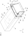
- FIG. 4 is a perspective view that shows the control unit 30.
- the control unit 30 has an electric components box 40, a first electric part 41, a link 42, a wall member 50, a holding member 60, and a second electric part 70.
- the electric components box 40 is for example, a long-rectangular box that extends in the left-right direction Y. As shown in FIG. 2 , the electric components box 40 is disposed on the inside of the blower room 11a. The electric components box 40 is separately disposed on the top side of the blower 15, in the inside of the blower room 11a. The electric components box 40 is located on a top end portion, in the inside of the blower room 11a. The electric components box 40 is fixed to the housing 11. An end of the electric components box 40 on the right side, is separately located more to the left side than the partition member 11c.
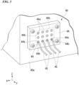
- FIG. 5 is a perspective view that shows a portion of the electric components box 40.
- a lead-out hole 40b is formed on the electric components box 40.
- the lead-out hole 40b in the present invention is formed on a right side wall 40a that is located on the right side (+Y side), out of the wall portions that configure the electric components box 40.
- the right side wall 40a is a wall on a side that is near to the mechanical room 11b, out of the wall portions of the electric components box 40 in the left-right direction Y.
- the lead-out hole 40b penetrates the right side wall 40a in the left-right direction Y.
- the lead-out hole 40b is square shaped.
- the lead-out hole 40b is formed on a center in the vertical direction Z, in a portion of the front side (+X side) out of the right side wall 40a.
- a cover material 44 is fixed to a right side surface of the right side wall 40a of the electric components box 40.
- the cover material 44 plugs the lead-out hole 40b from an outside of the electric components box 40.
- the cover material 44 is a rectangular shaped material that flattens in the left-right direction Y.
- Each corner out of four corners of the cover material 44 as seen from the right side (+Y side) is fixed to the right side wall 40a using a bolt.
- the cover material 44 has a plurality of thin portions 44a. A thickness of a thin portion 44a compared to portions other than the thin portion 44a out of the cover material 44, is thinner in the left-right direction Y.
- At least one thin portion 44a out of the plurality of thin portions 44a has a wire hole 44b that passes a wire 45 to be mentioned later on, through formed therein.
- the wire hole 44b is formed for example, by cutting slits into the thin portion 44a.
- FIG. 5 shows a situation where all of the thin portions 44a have wire holes 44b formed therein.
- a portion of wires 45 that are inserted through the wire holes 45b however, are omitted from the drawing.
- an operator conducting lead-out work of the wires 45 from within the electric components box 40 to cut slits onto the thin portions 44a to form a wire hole 44b, so as to only form the needed wire holes 44b.
- a circumferential edge of the wire hole 44b is elastically deformable.
- the circumferential edge of the wire hole 44b in the present disclosure is formed by the thin portion 44a.
- the circumferential edge of the wire hole 44b is elastically deformable so as to be widened in a direction that the wire 45 is inserted through, when inserted through the wire hole 44b, while being in close contact with an outer surface of the wire 45.
- the cover material 44 may be configured of any material, so long as the circumferential edge of the wire hole 44b is elastically deformable.
- the material that the cover material 44 is configured from may be an elastomer of rubber or the like, or may be a resin.
- the first electric part 41 is housed on an inside of the electric components box 40.
- a plurality of first electric parts 41 are provided.
- the plurality of first electric parts 41 include a substrate 41a, a micro-computer 41b, and a connection component 41c.
- the substrate 41a is a rectangular shaped plate surface that faces the vertical direction Z.
- the substrate 41a is a first control board having a control circuit mounted thereon, that controls the outdoor unit 10.
- the micro-computer 41b and the connection component 41c are attached to the substrate 41a.
- the micro-computer 41b conducts control of each part of the outdoor unit 10.
- the connection component 41c switches a connection state of a portion of the control circuit mounted on the substrate 41a.
- the link 42 protrudes to the right side, from a top end of the electric components box 40.
- the link 42 is a flat rectangular shaped in the vertical direction Z. As shown in FIG. 3 , a right end of the link 42 is separately located on a top side of the partition member 11c. The link 42 is located on the top side more than the lead-out hole 40b.
- the holding member 60 is disposed on the inside of the mechanical room 11b.
- the holding member 60 is fixed to the electric components box 40 via the link 42 and the wall member 50.
- the holding member 60 is a member that holds the second electric part 70.
- FIG. 6 is an exploded perspective view that shows a portion of the control unit 30.
- the holding member 60 has a first holding member 61, and a second holding member 62.
- the first holding member 61 and the second holding member 62 in the present embodiment are members that are different from one another.
- the first holding member 61 and the second holding member 62 are sheet metal members.
- the first holding material 61 and the second holding material 62 are fixed to one another.
- the first holding member 61 has a first holding wall 61a, a bottom wall 61b, a rear wall 61c, and a protruding wall 61d.
- the first holding wall 61a is a long semi-rectangular plate in the front-rear direction X.
- a plate surface of the first holding wall 61a inclines towards the left-right direction Y with respect to a plane (ZX plate) that is orthogonal to the left-right direction Y.
- the first holding wall 61a is located on the left side (-Y side) as the top side thereof is approached.
- the bottom wall 61b protrudes to the right side (+Y side), from a bottom end of the first holding wall 61a.
- the rear wall 61c protrudes to the left side, from the rear end of the first holding wall 61a.
- the protruding wall 61d protrudes to the rear side (-X side), from a left end of the rear wall 61c.
- the protruding wall 61d is fixed to a rear end of the second wall 52.
- the second holding member 62 is located on a front side (+X side) of the first holding member 61.
- the second holding member 62 has a second holding wall 62a, and a protruding wall 62b.
- the second holding wall 62a is a semi-rectangular plate.
- a plate surface of the second holding wall 62a faces the front-rear direction X.
- the plate surface of the second holding wall 62a is surface that is orthogonal to the front-rear direction X.
- the second holding wall 62a is fixed to an end in the front side of the first holding wall 61a.
- the protruding wall 62b protrudes to the front side, from a left end of the second holding wall 62a.
- the protruding wall 62b is fixed to the second wall 52 to be mentioned later on.
- the second electric part 70 is held by the holding member 60.
- the second electric part 70 is electrically connected to the substrate 41a by the wires 45 to be mentioned later on.
- a plurality of second electric parts 70 is provided.
- the plurality of second electric parts 70 include a substrate 70a and a terminal block 70b.
- the substrate 70a is a plate surface which is a rectangular plate shape that faces the top side as well as the right side.
- the substrate 70a is held by the first holding member 61. More specifically, the substrate 70a is fixed to a surface that the top side of the first holding wall 61a faces.
- a sensor that is not shown on the drawings, and that is disposed on the inside of the mechanical room 11b is electrically connected to the substrate 70a.
- the substrate 70a is a second control board having a signal input thereto, from the sensor which is not shown on the drawings.
- a connection component is mounted on the substrate 70a as with the substrate 41a, and said connection component has explosion proof treatment applied thereto. As such, even if the refrigerant 19 leaks and comes into contact with said connection component, it is possible to suppress any failures from occurring.
- the terminal block 70b is held by the second holding member 62.
- the terminal block 70b is fixed to a surface on the front side (+X side) of the second holding wall 62a out of the second holding member 62.
- the wall member 50 is located on the top side of the partition member 11c.
- the wall member 50 is located between the partition member 11c and the ceiling surface panel 11f in the vertical direction Z.
- the wall member 50 plugs a gap between the partition member 11c and the ceiling surface panel 11f.
- the wall member 50 has the first wall 51 and the second wall 52.
- the first wall 51 and the second wall 52 are members that are separate from one another.
- the wall member 50 is configured from the first wall 51 and the second wall 52 being fixed to one another.
- the first wall 51 is located on the left side of the second wall 52.
- the first wall 51 is located between the electric components box 40 and the inside of the mechanical room 11b in the left-right direction Y.
- the first wall 51 is separately disposed from the right side of the electric components box 40.
- the first wall 51 is disposed so as to face the right side wall 40a of the electric components box 40 with an interval in between.
- the first wall 51 extends in the front-rear direction X.
- the first wall 51 in the present embodiment is a sheet metal member.
- the first wall 51 has a first wall main body 51a, a rear wall 51b, a protruding wall 51c, a front wall 51d, and an eave wall 51h.
- the first wall main body 51a extends in the front-rear direction X.
- the first wall main body 51a is a plate shape having a plate surface that faces the left-right direction Y.
- the first wall main body 51a is a long semi-rectangular shape in the front-rear direction X, as seen from the left-right direction Y.
- a top end of the first wall main body 51a is fixed to a right end of the link 42 by bolts.
- the first wall main body 51a has a recessed wall 51e.
- the recessed wall 51e recesses to the left side (-Y side) more than portions other than the recessed wall 51e out of the first wall main body 51a.
- the recessed wall 51e in the present embodiment is a portion other than a top end portion, and portions on both ends in the front-rear direction X, out of the first wall main body 51a.
- the recessed wall 51e protrudes to the left side.
- the recessed wall 51e has an inclined wall 51i that extends in an inclination direction with respect to the vertical direction Z.
- the inclined wall 51i is located on the left side as the bottom side is approached.
- a surface that faces the right side out of the recessed wall 51e is an opposite surface 51j that faces the second wall 52.
- the opposite surface 51j is a surface out of the first wall 51 that faces a first space 50a, to be mentioned later on.
- the opposite surface 51j has an inclined surface 51f and an extension surface 51g.
- the inclined surface 51f inclines to the left-right direction Y with respect to the vertical direction Z.
- the inclined surface 51f is located on the left side, as the bottom side is approached. In other words, the inclined surface 51f inclines to a direction that approaches the electric components box 40, as the bottom side is approached in the vertical direction Z.
- the inclined surface 51f faces the right side and the bottom side.
- the extension surface 51g extends to the bottom side from an end on the bottom side of the inclined surface 51f.
- the rear wall 51b protrudes to the right side, from a rear end of the first wall main body 51a.
- the protruding wall 51c protrudes to the rear side (+Y side), from a right end of the rear wall 51b.
- the front wall 51d protrudes to the right side, from a front end of the first wall main body 51a.
- the eave wall 51h protrudes to the left side, from the top end of the first wall main body 51a.
- the eave wall 51h extends in the front-rear direction X.
- the eave wall 51h is a plate shape having a plate surface that faces the vertical direction Z. As shown in FIG.
- the eave wall 51h is hooked onto a right end of the link 42 from the top side.
- a sealing member is provided between the eave wall 51h and the ceiling surface panel 11f. Said sealing member is fixed to a bottom surface of the ceiling surface panel 11f.
- first through holes 81 that penetrate the first wall 51 in the left-right direction Y are formed on the first wall 51.
- the first through holes 81 are formed on a bottom end of the recessed wall 51e.
- the first through holes 81 penetrate the recessed wall 51e in the left-right direction Y.
- the first through holes 81 extend in the vertical direction Z.
- the first through holes 81 open to the bottom side. Top ends of the first through holes 81 are semi-circular arcs that convex to the top side.
- the wires 45 to be mentioned later on are inserted through the first through holes 81.
- a plurality of first through holes 81 are formed in the front-rear direction X with intervals therebetween.
- the first through holes 81 are formed from four through holes, a first through hole 81a, a first through hole 81b, a first through hole 81c, and a first through hole 81d.
- the first through hole 81a, the first through hole 81b, the first through hole 81c, and the first through hole 81d are aligned in such order, and face the rear side (-X side) from the front side (+X side).
- a top end of the first through hole 81b and a top end of the first through hole 81c are located more to the top side than a top end of the first through hole 81a and a top end of the first through hole 81b.
- An interval in the front-rear direction X between the first through hole 81b and the first through hole 81c is larger than the interval between the first through hole 81a and the first through hole 81b in the front-rear direction X, and the interval between the first through hole 81c and the first through hole 81d in the front-rear direction X.
- FIG. 7 is a view showing a portion of the control unit 30 as seen from the right side.
- the holding member 60 and the second electric parts 70 are omitted.
- each through hole out of the first through holes 81 that is formed on the first wall 51 is located in the bottom side more than the lead-out hole 40b.
- the first through hole 81a and the first through hole 81b are located in the bottom side of the lead-out hole 40b, as seen from the left-right direction Y.
- the second wall 52 is located on a right side of the first wall 51.
- the second wall 52 is located between the first wall 51 and the inside of the mechanical room 11b in the left-right direction Y.
- the second wall 52 extends in the front-rear direction X.
- a dimension of the second wall 52 in the front-rear direction X is smaller than a dimension of the first wall 51 in the front-rear direction X.
- the second wall 52 in the present embodiment is a sheet metal member.
- the second wall 52 has a second wall main body 52a.
- the second wall main body 52a has a plate surface that faces the left-right direction Y, and is a long semi-rectangular shaped plate in the front-rear direction X.
- the second wall main body 52a is located on the right side of the first wall main body 51a.
- the second wall main body 52a is fixed to the first wall main body 51a by bolts. A portion of the bolt used to fix the second wall main body 52a to the first wall main body 51a mutually fastens the first wall 51 and the second wall 52 to the link 42.
- a top end of the second wall main body 52a is fixed to a top end of the first wall main body 51a by a bolt.
- Both ends of the second wall main body 52a in the front-rear direction X are each fixed to both ends of the first wall main body 51a.
- the second wall main body 52a covers the first wall main body 51a and the recessed wall 51e from the right side.
- the second wall main body 52a is located between the rear wall 51b and the front wall 51d in the front-rear direction X.
- the second wall 52 has a flange 52b.
- the flange 52b protrudes to the left side from an end of the bottom side of the second wall main body 52a.
- the flange 52b protrudes to a direction out of the left-right direction Y that approaches the first wall 51, from an end of the second wall main body 52a on the bottom side in the vertical direction.
- the flange 52b has a plate surface that faces the vertical direction Z, and is a long-thin rectangular shape that extends in the front-rear direction X.
- the flange 52b is disposed on top of an end of the top side of the partition member 11c in the vertical direction.
- the flange 52b in the present embodiment is mounted on the top side of the bend 11e of the partition member 11c.
- a sponge material 93 is disposed between the flange 52b and the bend 11e. By sandwiching the sponge material 93 in the vertical direction Z between the flange 52b and the bend 11e, the sponge material 90 is in a state of compressive elastic deformation in the vertical direction Z.
- the flange 52b and the bend 11e are connected via the sponge material 93.
- the second wall 52 has an engagement portion 52c that protrudes to the bottom side from the left end of the flange 52b.
- the engagement portion 52c is a plate surface that faces the left-right direction Y, having a long thin rectangular shape that extends in the front-rear direction X.
- the engagement portion 52c is located on the left side of a top end of the partition plate 11d of the partition member 11c. In FIG. 3 , the engagement portion 52c faces the left-right direction Y via an interval and the partition plate 11d.
- two second through holes 82 that penetrate the second wall 52 in the left-right direction Y are formed on the second wall 52.
- the second through holes 82 in the present embodiment are formed on the second wall main body 52a.
- the second through holes 82 penetrate the second wall main body 52a in the left-right direction Y.
- the second through holes 82 extend in the front-rear direction X.
- the second through hole 82 opens to an edge of the second wall main body 52a in the front-rear direction X.
- a plurality of second through holes 82 are formed.
- the second through holes 82 are formed from four through holes, a second through hole 82a, a second through hole 82b, a second through hole 82c, and a second through hole 82d.
- the second through hole 82a and the second through hole 82b are formed on an end in the front side (+X side) of the second wall main body 52a.
- the second through hole 82a and the second through hole 82b open to the front side.
- Rear edges of second through holes 82a and 82b are semi-circular arcs that convex to the rear direction (-X side).
- the second through hole 82a and the second through hole 82b are adjacently disposed in the vertical direction Z, with an interval therebetween.
- the second through hole 82a is located on a bottom side of the second through hole 82b.
- a rear end of the second through hole 82b is located more to the rear side than a rear end of the second through hole 82a.
- the second through hole 82c and the second through hole 82d are formed on an end in the rear side (-X side) of the second wall main body 52a.
- the second through hole 82c and the second through hole 82d open to the rear side.
- Front ends of second through holes 82c and 82d are semi-circular arc shapes that convex to the front side (+X side).
- the second through hole 82c and the second through hole 82d are adjacently disposed with an interval therebetween, in the vertical direction Z.
- the second through hole 82d is located on the bottom side of the second through hole 82c.
- a front end of the second through hole 82c is located on the front side more than the second through hole 82d.
- the second through holes 82 in the second wall 52 are located on the top side more than the first through holes 81 that are formed on the first wall 51.
- the first through holes 81 that are formed on the first wall 51 and the lead-out hole 40b, and the second through holes 82 that are formed on the second wall 52 are disposed in locations that are offset from one another.
- Top ends of second through holes 82b and 82c are located on the top side more than the lead-out hole 40b.
- the second through holes 82b and 82c are located on the top side more than an entirety of the lead-out hole 40b. Bottom ends of the second through holes 82a and 82d are located more to the bottom side than the lead-out hole 40b.
- the second through holes 82a and 82b are located more to the front side (+X side) than the lead-out hole 40b and the first through hole 81.
- the second through holes 82c and 82d are located more to the rear side (-X side) than the lead-out hole 40b and the first through hole 81.
- the second through holes 82 face the opposite surface 51j of the first wall 51, in the left-right direction Y.
- the second through hole 82b and the second through hole 82c incline towards the inclined surface 51f in the left-right direction Y.
- FIG. 8 is a perspective view showing a portion of the partition member 11c and a portion of the control unit 30.
- the first space 50a is formed between the first wall 51 and the second wall 52.
- the first space 50a in the present embodiment is a space that is surrounded by the recessed wall 51e out of the first wall 51, and the second wall main body 52a out of the second wall 52.
- both ends in the front-rear direction X out of the first space 50a are closed off.
- the first space 50a has an opening 50b that opens to the bottom side.
- the opening 50b is a left side part out of ends on the bottom side of the first space 50a.
- the opening 50b opens to the inside of the blower room 11a.
- a right side part out of ends on the bottom side of the first space 50a is closed by the flange 52b of the second wall 52.
- the opening 50b is located on the bottom side, more than the lead-out hole 40b.
- the opening 50b is formed between a bottom end of the first wall 51 and the left end of the flange 52b.
- the control unit 30 includes the sponge material 90 disposed in the first space 50a.
- the sponge material 90 is a porous member that is elastically deformable.
- the sponge material 90 includes a first sponge material 91 and a second sponge material 92.
- the first sponge material 91 is a surface that is attached to a surface out of the first wall 51 that faces the first space 50a, in other words, the opposite surface 51j. More specifically, the first sponge material 91 is attached to the extension surface 51g.
- the second sponge material 92 is attached to a surface out of the second wall 52 that faces the first space 50a, in other words, a surface on the left side of the second wall main body 52a.
- the first sponge material 91 and the second sponge material 92 are disposed so as to face the left-right direction Y. A portion of a surface on the right side of the first sponge material 91 and a portion of a surface on the left side of the sponge material 92 are in contact with one another. A portion in the vertical direction Z out of the first space 50a is plugged by the first sponge material 91 and the second sponge material 92.
- a second space 60a is formed between the wall member 50 and the holding member 60.
- the second space 60a in the present embodiment is a space that is surrounded by the second wall main body 52a of the second wall 52, the first holding wall 61a and the rear wall 61c of the first holding member 61, and the second holding wall 62a of the second holding member 62.
- the second space 60a is open to both sides in the vertical direction Z. Both ends of the second space 60a in the vertical direction Z are open to the inside of the mechanical room 11b.
- the second space 60a is connected to the first space 50a via the second through holes 82 that are formed on the second wall 52.
- the control unit 30 has the wire 45 extend from the lead-out hole 40b formed on the electric components box 40, to the inside of the mechanical room 11b.
- a plurality of wires 45 are provided in the present embodiment.
- the plurality of wires 45 in the present embodiment includes the wire 45 connected to the second electric parts 70 in the mechanical room 11b, and the wire 45 connected to the compressor 12 in the mechanical room 11b. Out of the wires that are connected to the compressor 12 in the mechanical room 11b, a power line that supplies electric power to the compressor 12 is included.
- each of the wires 45 in the electric components box 40 is connected to the substrate 41a.
- Each of the wires 45 in the present embodiment are pulled out to an outside of the electric components box 40 from the inside of the electric components box 40, passing through the lead-out hole 40b and the wire hole 44b.
- the wire 45 that is pulled out to the outside of the electric components box 40 extends to the bottom side between the electric components box 40 and the first wall 51, passes through a through hole out of the first through holes 81, and enter the first space 50a.
- the wires 45 that have entered into the first space 50a extend to the top side to pass through the second through holes 82, and enter into the second space 60a.
- a wire 45 extends from the inside of the blower room 11a to the inside of the mechanical room 11b, passes through a through hole out of the second through holes 82 that is formed on the first space 50a and the second wall 52.
- the wires 45 pulled out to the inside of the mechanical room 11b are connected to other components disposed on the inside of the mechanical room 11b, such as the second electric parts 70 or the compressor 12. Accordingly, the first electric parts 41 disposed on the inside of the blower room 11a, and the second electric parts 70 disposed on the inside of the mechanical room 11b are electrically connected to one another by the wires 45.
- the plurality of wires 45 configure a plurality of wire bundles 45a, 45b, 45c and 45d, which are two or more wires 45 that are bundled together.
- four wire bundles, 45a, 45b, 45c, and 45d are formed.
- Wire bundle 45a is pulled out to the inside of the mechanical room 11b, passing through the first through hole 81a and the second through hole 82a.
- Wire bundle 45b is pulled out to the inside of the mechanical room 11b, passing through the first through hole 81b and the second through hole 82b.
- Wire bundle 45c is pulled out to the inside of the mechanical room 11b, passing through the first through hole 81c and the second through hole 82c.
- Wire bundle 45d is pulled out to the inside of the mechanical room 11b, passing through the first through hole 81d and the second through hole 82d.
- the plurality of wires 45 configure each of the wire bundles 45a, 45b, 45c, and 45d by bundling a number of the wires 45, based on a purpose of each of the wires 45. Out of the plurality of wires 45, the wires 45 having a similar purpose are bundled together. In other words, purposes of the wires 45 in each of the wire bundles 45a, 45b, 45c, and 45d are different from one another. As an example, the wires 45 included in the wire bundle 45a connect the substrate 41a and the substrate 70a, and are used to transmit signals between the substrate 41a and the substrate 70a.
- the wires 45 included in the wire bundle 45b are power lines that supply electric power, which is supplied from the outside, to the electric parts of the second electric parts 70 or the like.
- the wires 45 included in the wire bundle 45c are power lines that are connected to the compressor 12, and supply electric power to the compressor 12.
- the wires 45 included in the wire bundle 45d are wires that are connected to a part that rectifies a high frequency current.
- the wires 45 of the wire bundles 45a, 45b, 45c, and 45d which have purposes that differ from one another are inserted through the mutually differing first through holes 81, and through the mutually differing second through holes 82.
- the term "purposes of the wires... differ from one another" may refer to wires being connected to differing parts, or may refer to the wires being connected for differing purposes.
- the wires being connected for differing purposes includes transmitting electrical signals, supplying electric power, or the like. For example, even if two wires are connected to the same part, if the two wires are connected for differing purposes, then said two wires have differing purposes from one another. Also, even if the two wires are connected for the same purpose, if the two wires are connected to differing parts, the two wires then have differing purposes from one another.
- the plurality of wire bundles 45a, 45b, 45c and 45d may include two or more of the wires 45 that mutually have the same purpose as one another.
- the control unit 30 includes the electric components box 40 disposed on the inside of the blower room 11a, the wires 45 that extend to the inside of the mechanical room 11b, after being pulled out from the lead-out hole 40b formed on the electric components box 40, the first wall 51 that is located between the electric components box 40 and the inside of the mechanical room 11b, and the second wall 52 that is located between the first wall 51 and the inside of the mechanical room 11b.
- the refrigerant 19 even if the refrigerant 19 leaks from the refrigerant pipe 18a disposed on the inside of the mechanical room 11b, it is possible to at least obstruct a portion of the refrigerant 19 that has leaked using the first wall 51 and the second wall 52, making it possible to suppress the refrigerant 19 from flowing to the inside of the electric components box 40 of the blower room 11a.
- the refrigerant 19 that leaks to the inside of the mechanical room 11b may for example, be in a gaseous state.
- the first space 50a is formed as a space between the first wall 51 and the second wall 52.
- the wires 45 extend from the inside of the blower room 11a to the inside of the mechanical room 11b, via the first space 50a and the second through holes 82 that are formed on the second wall 52.
- a surface out of the first wall 51 that faces the first space 50a faces the second through holes 82 that are formed on the second wall 52, in the left-right direction Y.
- An end of the top side out of the first space 50a in the vertical direction, and both ends in the front-rear direction X that intersect with the vertical direction Z out of the first space 50a and that are orthogonal to the left-right direction Y are closed.
- the first space 50a has the opening 50b that opens to the bottom side in the vertical direction.
- the opening 50b opens to the inside of the blower room 11a. Accordingly, even in a case where the refrigerant 19 that has leaked to the inside of the mechanical room 11b, passing through the second through holes 82, flows to the inside of the first space 50a, since the refrigerant 19 that has leaked to the inside of the first space 50a is intercepted by the opposite surface 51j which faces the first space 50a out of the first wall 51, it is possible to suppress the refrigerant 19 from moving towards the electric components box 40.
- the refrigerant 19 that collides with the opposite surface 51j flows along the opposite surface 51j, and flows to the inside of the blower room 11a from the opening 50b, to the bottom direction. Accordingly, it is possible to suppress the refrigerant 19 from heading towards the electric components box 40, while guiding the refrigerant 19 to the inside of the blower room 11a so as to have the refrigerant 19 disperse using the air flow generated by the blower 15. As such, it is possible to suppress the refrigerant 19 from being retained on the inside of the housing 11.
- the exhausted refrigerant 19 is dispersed due to a collision with the second wall 52, and a speed of flow of the refrigerant 19 drops.
- the present disclosure it is possible to suitably suppress the refrigerant 19 from penetrating to the inside of the electric components box 40. Accordingly, it is possible to suppress the refrigerant 19 from causing any failures to the first electric parts 41 housed on the inside of the electric components box 40.
- the refrigerant 19 By simply providing a shield plate that covers the lead-out hole 40b for example, it would be possible to suppress the refrigerant 19 from leaking to the inside of the lead-out hole 40b. In such case however, the refrigerant 19 that is not blocked by the shield plate leaks into the lead-out hole 40b. Also, by the refrigerant 19 colliding with the shield plate, the refrigerant 19 flows towards an unintended direction or the like on the inside of the blower room 11a, and there is a risk of the refrigerant 19 leaking to the inside of the electric components box 40 from parts other than the lead-out hole 40b of the electric components box 40.
- the refrigerant 19 that flows to the inside of the first space 50a is guided to the bottom side on the inside of the blower room 11a, and it is possible suppress the refrigerant 19 from reaching the lead-out hole 40b. Accordingly, it is possible to suppress the refrigerant 19 from flowing to an unintended direction on the inside of the blower room 11a, and it is possible to suppress the refrigerant 19 from leaking to the inside of the electric components box 40 from the top side of the electric components box 40 and/or from both sides or the like of the electric components box 40 in the front-rear direction X. Therefore, according to the present embodiment, compared to the previously mentioned case of simply providing the shield plate, it is possible to suitably suppress the refrigerant 19 from leaking to the inside of the electric components box 40.
- the control unit 30 has the first electric parts 41 housed on the inside of the electric components box 40, the holding member 60 disposed on the inside of the mechanical room 11b, and the second electric parts 70 that are held by the holding member 60.
- the control unit 30 by disposing a portion of the electric components included in the control unit 30 on the inside of the mechanical room 11b, it is easy to conduct connection work between sensors or the like that are disposed on the inside of the mechanical room 11b, and the control unit 30. Maintenance work or the like becomes easier to conduct by disposing the second electric parts 70, as parts that readily need maintenance work or the like conducted by the operator, on the inside of the mechanical room 11b.
- the opening 50b of the first space 50a is located more to the bottom side in the vertical direction than the lead-out hole 40b.
- density of the refrigerant 19 in a gaseous state is larger than the density of air
- since the refrigerant 19 in the gaseous state that is discharged from the opening 50b flows to the bottom direction due to gravity it is possible to even more suitably suppress the refrigerant 19 discharged from the opening 50b, from heading towards the lead-out hole 40b. Therefore, it is possible to more suitably suppress the refrigerant 19 from leaking to the inside of the electric components box 40.
- the first through holes 81 are formed on the first wall 51 as through holes through which the wires 45 are inserted through.
- the first through holes 81 that are formed on the first wall 51 are located more to the bottom side in the vertical direction, than the lead-out hole 40b.
- the density of the refrigerant 19 in the gaseous state is larger than the density of air, it is possible to have the refrigerant 19 that passes through the first through holes 81 flow in a direction that is far from the lead-out hole 40b, and it is possible to further suppress the refrigerant 19 from flowing to the lead-out hole 40b. Therefore, it is possible to more suitably suppress leaking of the refrigerant 19 to the inside of the electric components box 40.
- the second through holes 82 which are through holes that are formed on the second wall 52 are located on the top side in the vertical direction, more than the first through holes 81 that are formed on the first wall 51.
- the wires 45 that are pulled out from the lead-out hole 40b extend to the top side of the inside of the first space 50a to pass through the second through holes 82, after extending to the bottom side to pass through the first through holes 81. Accordingly, it is possible to pull out the wires 45 from the lead-out hole 40b to the inside of the mechanical room 11b, by having the wires 45 meander in the vertical direction Z.
- the lead-out hole 40b, the first through holes 81 that are formed on the first wall 51, and the second through holes 82 that are formed on the second wall 52 are located so as to be offset from one another, as seen from the left-right direction Y.
- the lead-out hole 40b, the first through holes 81 that are formed on the first wall 51, and the second through holes 82 that are formed on the second wall 52 are disposed so as to be offset from one another in the vertical direction Z and in the front-rear direction X.
- the wires 45 passing through the lead-out hole 40b, the first through holes 81, and the second through holes 82 be more complex, it is also possible to suppress foreign substances such as rain water or the like that has leaked to the inside of the blower room 11a from leaking to the inside of the mechanical room 11b by being transmitted using the wires 45.
- the wires 45 are provided in plurality.
- the first through holes 81 that formed on the first wall 51, and the second through holes 82 that are formed on the second wall 52, are each formed in plurality.
- Two or more wires 45 of the plurality of wires 45 bundled together configure the plurality of wire bundles 45a to 45d.
- the plurality of wire bundles 45a to 45d include at least two wire bundles that mutually have differing purposes of the wires 45, and said at least two wire bundles are inserted through the first through holes 81 and the second through holes 82 that differ from one another. As such, it is possible to separately dispose two wires 45 that have differing purposes, in between said at least two wire bundles.
- the noise generated by the wire 45 which is the power line of the compressor 12, and the wire 45 which is connected to the part that rectifies the high frequency current is higher than the noise generated by the wire 45 which is a power line that supplies electric power to the second electric parts 70 or the like, and the wire 45 which is a transmission line that connects the substrates 41a and 70a to one another.
- the size of the noise generated in the wires 45 that are included in the wire bundles 45c and 45d is larger than the size of the noise generated in the wires 45 that are included in the wire bundles 45a and 45b.
- the noise generated by the wire 45 which is a power line that supplies electric power to the second electric parts 70 or the like, in other words the wire 45 included in the wire bundle 45b, is larger than the noise generated by the wire 45 which is a transmission line that connects the substrates 41a and 70a to one another, in other words the wire 45 included in the wire bundle 45a.
- the wire 45 of the wire bundle 45a be separately disposed from the wire bundles 45b, 45c, and 45d, so that the noise generated in the other wires 45 does not transfer to the wire 45 of the wire bundle 45a.
- the wire bundle 45a is inserted through the first through holes 81 and second through holes 82 that are different from the through holes through which the wire bundles 45b, 45c, and 45d having different purposes are inserted through, it is possible to suitably and separately dispose the wire 45 included in the wire bundles 45a from the wire bundles 45b, 45c, and 45d. As such, it is possible to make the transfer of the noise generated in the wire bundles 45b, 45c, and 45d to the wire 45 of the wire bundle 45a more difficult. Therefore, it is possible to suppress the disruption of the voltage signal flowing through the wire 45 included in the wire bundle 45a, and it is possible to conduct better transmission between the substrates 41a and 70a.
- the noise generated from the wire 45 included in the wire bundle 45b is used to obtain a noise standard. As such, it is preferable to have the noise effects generated in the other wires 45 not be easily received by the wire 45 included in the wire bundle 45b.
- the wire bundle 45b is inserted through the first through holes 81 and second through holes 82 that are different from the through holes through which the wire bundles 45a, 45c, and 45d having different purposes are inserted through, it is possible to suitably and separately dispose the wire 45 included in the wire bundles 45b from the wire bundles 45a, 45c, and 45d.
- a surface out of the first wall 51 that faces the first space 50a in other words the opposite surface 51j, has the inclined surface 51f that inclines towards a direction that approaches the electric components box 40 as the bottom side in the vertical direction is approached, and has the extension surface 51g that extends to the bottom side in the vertical direction from an end in the bottom side of the inclined surface 51f in the vertical direction.
- the inclined surface 51f faces the second through holes 82 formed on the second wall 52 in the left-right direction Y.
- the refrigerant 19 that passes through the second through holes 82 in the left-right direction Y and flows to the inside of the first space 50a from the inside of the mechanical room 11b be suitably guided to the bottom side, by having the refrigerant 19 collide with the inclined surface 51f.
- the refrigerant 19 that is guided to the bottom side by the inclined surface 51f flows to the bottom side along the extension surface 51g, and is discharged to the bottom direction from the opening 50b to the inside of the blower room 11a from the rear wall 51b. Accordingly, it is possible to suppress the refrigerant 19 from reaching the inside of the lead-out hole 40b.
- the material of the first wall 51 is sheet metal, and the recessed wall 51e is made by press working, by making a shape of the recessed wall 51e be a shape where the inclined surface 51f is provided, making of the recessed wall 51e becomes easier.
- the control unit 30 includes the lead-out hole 40b and the cover material 44.
- the cover material 44 has the wire hole 44b which passes the wire 45 through.
- the circumferential edge of the wire hole 44b is elastically deformable. As such, it is possible to plug the lead-out hole 40b by the cover material 44, while having the circumferential edge of the wire hole 44b be in close contact with the wire 45. Accordingly, even when in a case where the refrigerant 19 flows close to the lead-out hole 40b, it is possible to suppress the refrigerant 19 from leaking to the inside of the lead-out hole 40b using the cover material 44. Therefore, it is possible to more suitable suppress the refrigerant 19 from leaking to the inside of the electric components box 40.
- the control unit 30 has the sponge material 90 disposed in the first space 50a. As such, it is possible to decrease the speed of flow of the refrigerant 19 that flows to the inside of the first space 50a, using the sponge material 90. As such, it is possible to prevent the refrigerant 19 from intensely flowing to the inside of the blower room 11a, and it is possible to more suitably suppress the refrigerant 19 from leaking to the inside of the electric components box 40. When foreign substances such as rain water or the like leak to the inside of the blower room 11a from the outside of the outdoor unit 10, even if said foreign substances make it to the inside of the first space 50a, it is possible to intercept said foreign substances using sponge material 90.
- the second through holes 82 are located more to the top side than the lead-out hole 40b, it is possible to have the location of the second through holes 82 be relatively more to the top side in the vertical direction Z, and said foreign substances such as rain water or the like are suppressed from reaching an inside of the second through holes 82. As such, it is possible to further suppress said foreign substances such as rain water or the like from leaking to the inside of the mechanical room 11b via the second through holes 82.
- the sponge material 90 includes the first sponge material 91 which is attached to a surface out of the first wall 51 that faces the first space 50a, and the second sponge material 92 which is attached to a surface out of the second wall 52 that faces the first space 50a.
- Out of the wire 45 at least a portion out of a part located on the inside of the first space 50a is sandwiched between the first sponge material 91 and the second sponge material 92.
- the second wall 52 has the second wall main body 52a, and the flange 52b which protrudes to a direction out of the left-right direction Y that approaches the first wall 51, from an end of the second wall main body 52a on the bottom side in the vertical direction.
- the flange 52b is disposed on top of the end of the partition member 11c on the top side in the vertical direction.
- the sealing member that is not shown on the drawings is provided between the eave wall 51h and the ceiling surface panel 11f, the refrigerant 19 that has leaked on the inside of the mechanical room 11b is suppressed from flowing to the top side of the electric components box 40, from in between the first wall 51 and the ceiling surface panel 11f. Accordingly, it is possible to suppress the refrigerant 19 from leaking to the inside of the electric components box 40, from the top side of the electric components box 40.
- a first wall and a second wall may be an integral member. So long as a control unit is disposed so as to straddle between an inside of a first room (the blower room 11a) and an inside of a second room (the mechanical room 11b), a part out of the control unit that is disposed on the inside of the second room may be any part. For example, electric components need not be disposed on the inside of the second room, and only a supporting member that supports a wire which extends from an inside of an electric components box may be disposed.
- a layout relationship of a lead-out hole, a through hole (the first through hole 81) that is formed on the first wall, and a through hole (the second through hole 82) that is formed on the second wall, may be any layout relationship.
- a number of the through holes that are formed on the first wall, and a number of the through holes that are formed on the second wall are not particularly limited.
- the through hole through which the wire passes through need not be formed on the first wall.
- a surface out of the first wall that faces a space (the first space 50a) need not include an inclined surface and/or an extension surface, and may be a surface that has any shape.
- a number of the wires that extend from the lead-out hole formed on the electric components box to the inside of the second room is not particularly limited.
- the plurality of wires may be bundled and inserted through the through hole that is formed on the first wall, and/or the through hole that is formed on the second wall.
- the plurality of wires need not be bundled, and may also be individually inserted through each of the differing through holes.
- a target to which the wires are connected to, on the inside of the second room is not particularly limited.
- the control unit need not include a cover material that plugs the lead-out hole.
- the control unit need not include a sponge material that is disposed in the space (the first space 50a).
- a heat exchange unit according to the present disclosure may be an indoor unit of a refrigeration cycle device.
- the refrigeration cycle device that includes the heat exchange unit in the present disclosure may be a device that utilizes a refrigeration cycle having a refrigerant that circulates within, and is not limited to an air-conditioning unit.
- the refrigeration cycle device may be a heat pump of a water heater.
Landscapes
- Engineering & Computer Science (AREA)
- Mechanical Engineering (AREA)
- General Engineering & Computer Science (AREA)
- Chemical & Material Sciences (AREA)
- Combustion & Propulsion (AREA)
- Physics & Mathematics (AREA)
- Thermal Sciences (AREA)
- Other Air-Conditioning Systems (AREA)
- Air Filters, Heat-Exchange Apparatuses, And Housings Of Air-Conditioning Units (AREA)
Abstract
Description
- The present disclosure relates to a heat exchange unit and refrigeration cycle device.
- An air conditioner having an electric components box mounted thereon is known. For example, in Patent Document 1, a shutter plate for closing a part of a slit used for passing through wires that are provided in an electric components box main body, is provided on a cover of the electric components box.
- [Patent Document 1]
Japanese Unexamined Application No. 2015-59735 - For example, in a shutter plate as the aforementioned, the object of providing such shutter plate is to suppress a refrigerant that has leaked from penetrating to an inside of an electric components box. With the aforementioned shutter plate however, there are cases where suppressing the refrigerant that has leaked from penetrating to the inside of the electric components box is not sufficient.
- The present disclosure has been made in order to address the problem above, and one object is to provide a heat exchange unit having a structure that suitably suppresses penetration of refrigerant to an inside of an electric components box, and to provide a refrigeration cycle device that includes such heat exchange unit.
- A heat exchange unit of a refrigeration cycle device according to the present disclosure includes: a housing having a first room and a second room that are portioned from one another by a partition member; a heat exchanger that is disposed on an inside of the first room; a blower that is disposed on the inside of the first room; a refrigerant pipe that is disposed on an inside of the second room and that is connected to the heat exchanger, and a control unit that is disposed so as to straddle between the inside of the first room and the inside of the second room. The first room and the second room are adjacently disposed in a first direction that intersects a vertical direction. The control unit has an electric components box disposed on the inside of the first room, a wire that extends to the inside of the second room after being pulled out from a lead-out hole, a first wall located between the electric components box and the inside of the second room, and a second wall located between the first wall and the inside of the second room. A space is formed between the first wall and the second wall. The wire extends from the inside of the first room to the inside of the second room, via the space, passing through a second through hole out of second through holes that are formed on the second wall. A surface out of the first wall that faces the space, faces the second through hole out of second through holes that are formed on the second wall in the first direction. An end of the top side out of the space in the vertical direction, and both ends in a second direction that intersects with the vertical direction and is orthogonal to the first direction out of the space, are closed off. The space has an opening that opens to the bottom side in the vertical direction, and the opening opens to the inside of the first room.
- A refrigeration cycle device according to the present disclosure includes an outdoor unit, and an indoor unit, wherein the outdoor unit or the indoor unit may be the heat exchange unit mentioned above.
- According to an embodiment of the present disclosure, in an electric components box of a refrigeration cycle device, it is possible to suitably suppress penetration of refrigerant to an inside of the electric components box.
-
- [
FIG. 1 ] A schematic view that shows an outline configuration of a refrigeration cycle device in an embodiment. - [
FIG. 2 ] A perspective view that shows a portion of an outdoor unit in the embodiment. - [
FIG. 3 ] A partial cross-sectional view that shows a portion of the outdoor unit in the embodiment. - [
FIG. 4 ] A perspective view that shows a control unit in the embodiment - [
FIG. 5 ] A perspective view that shows a portion of an electric components box in the embodiment. - [
FIG. 6 ] An exploded perspective view that shows a portion of the control unit in the embodiment. - [
FIG. 7 ] A view showing a portion of the control unit as seen from a right side in the embodiment. - [
FIG. 8 ] A perspective view showing a portion of a partition member and a portion of the control unit in the embodiment. - Hereinafter, an embodiment of the present disclosure is explained with reference to the drawings. The scope of the present disclosure is not limited to the embodiment below, and may be changed so long as the embodiment do not depart from the technical scope of the present disclosure. In the drawings below, scales and dimensions of various configurations may differ from scales and dimensions in the drawings below, to facilitate better understanding of the various embodiments.
- The drawings show an X axis, a Y axis, and a Z axis where appropriate. The X axis shows a side out of sides of a horizontal direction. The Y axis shows another side out of sides of the horizontal direction. The Z axis shows a vertical direction. In the explanation below, a horizontal direction along the X axis is referred to as a "front-rear direction X", and a horizontal direction along the Y axis is referred to as a "left-right direction Y". A vertical direction is referred to as a "vertical direction Z". The front-rear direction X, the left-right direction Y, and the vertical direction Z are mutually orthogonal directions. In the explanation below, a side out of sides of the vertical direction Z in which an arrow of the Z axis faces is a top side (+Z side). The other side out of sides of the vertical direction Z which faces an opposite side the arrow of the Z axis faces is a bottom side (-Z side). A side out of sides of the front-rear direction X in which an arrow of the X axis faces is a front side (+X side). A side out of sides of the front-rear direction X which faces an opposite side the arrow of the X axis faces is a rear side (-X side). The left-right direction Y in the embodiment below, is the left-right direction Y in a case where an
outdoor unit 10 is viewed from the front side (+X side). In other words, a side out of sides of the left-right direction Y in which an arrow of the Y axis faces is a right side (+Y side). A side out of sides in the left-right direction Y which faces an opposite side the arrow of the Y axis faces is a left side (-Y side). In the embodiment below, a direction where the left-right direction Y intersects with the vertical direction Z is referred to as a "first direction". The front-rear direction X corresponds to a "second direction" which intersects the vertical direction Z, and is orthogonal to the first direction. -
FIG. 1 is a schematic view that shows an outline configuration of arefrigeration cycle device 100 in the embodiment. Therefrigeration cycle device 100 is a device that uses a refrigeration cycle in which arefrigerant 19 is circulated. Therefrigeration cycle device 100 in the embodiment is an air conditioner. As shown inFIG. 1 , therefrigeration cycle device 100 includes theoutdoor unit 10, anindoor unit 20, and acirculation path 18. Theoutdoor unit 10 is disposed outdoors. Theindoor unit 20 is disposed indoors. Theoutdoor unit 10 and theindoor unit 20 are connected by thecirculation path 18 that circulates arefrigerant 19. Theoutdoor unit 10 and theindoor unit 20 are heat exchange units that conduct heat exchange with air. - By having the
refrigerant 19 that flows within thecirculation pathway 18, and theindoor unit 20 conduct heat exchange with air indoors, it is possible for theair conditioner 100 to adjust a temperature of the air indoors. A refrigerant such as a fluorine based refrigerant with a low global warming potential (GWP: Global Warming Potential), or a hydrocarbon based refrigerant or the like may be mentioned as examples of therefrigerant 19. A density of therefrigerant 19 in a gaseous state is larger than a density of air. Here, the fluorine based refrigerant with a low global warming potential is for example, HFC32. An example of the hydrocarbon based refrigerant is R290 (propane). Both the fluorine based refrigerant and the hydrocarbon based refrigerant are flammable refrigerants. - The
outdoor unit 10 includes ahousing 11, acompressor 12, aheat exchanger 13, aflow adjustment valve 14, ablower 15, a four-way valve 16, arefrigerant pipe 18a, and acontrol unit 30. Thecompressor 12, theheat exchanger 13, theflow adjustment valve 14, theblower 15, the four-way valve 16, therefrigerant pipe 18a and thecontrol unit 30 are housed on an inside of thehousing 11. - Out of the
circulation pathway 18, thecompressor 12, theheat exchanger 13, theflow adjustment valve 14, and the four-way valve 16 are provided on a portion located on the inside portion of thehousing 11. Out of thecirculation pathway 18, thecompressor 12, theheat exchanger 13, theflow adjustment valve 14, and the four-way valve 16 are connected by a portion located on the inside portion of thehousing 11. - Out of the
circulation pathway 18, the four-way valve 16 is provided on a part that is connected to a discharge side of thecompressor 12. By exchanging a portion of thecirculation pathway 18, it is possible for the four-way valve 16 to reverse a direction of flow of the refrigerant 19 within thecirculation pathway 18. When the path connected by the four-way valve 16 is the path of the four-way valve 16 that is shown by solid lines inFIG. 1 , the refrigerant 19 within thecirculation pathway 18 flows in the direction shown by the solid line arrow inFIG. 1 . On the other hand, when the path connected by the four-way valve 16 is the path of the four-way valve 16 that is shown by dashed lines inFIG. 1 , the refrigerant 19 flows within thecirculation pathway 18 in the direction shown by the dashed line arrow inFIG. 1 . - The
refrigerant pipe 18a is a pipe that configures a portion of thecirculation pathway 18. Therefrigerant pipe 18a is connected to a pipe that extends from theindoor unit 20. A plurality ofrefrigerant pipes 18a are provided on an inside of thehousing 11 of theoutdoor unit 10. - The
indoor unit 20 includes ahousing 21, aheat exchanger 22, ablower 23, and acontroller 24. Thehousing 21 houses theheat exchanger 22, theblower 23, and thecontroller 24 on an inside thereof. It is possible for theindoor unit 20 to have a cooling operation where the air of the room theindoor unit 20 is disposed in is cooled, and to have a heating operation where the air of the room theindoor unit 20 is disposed in is heated. - When the
indoor unit 20 is operated in the cooling operation, the refrigerant 19 that flows within thecirculation pathway 18 flows in the direction shown by solid lines inFIG. 1 . In other words, when theindoor unit 20 is operated in the cooling operation, the refrigerant 19 that flows within thecirculation pathway 18 circulates so as to return to thecompressor 12 after passing through thecompressor 12, theheat exchanger 13 of theoutdoor unit 10, theflow adjustment valve 14, and theheat exchanger 22 of theindoor unit 20 in such an order. During the cooling operation, theheat exchanger 13 of theoutdoor unit 10 functions as a condenser, and theheat exchanger 22 of theindoor unit 20 functions as an evaporator. - On the other hand, when the
indoor unit 20 is operated in the heating operation, the refrigerant 19 that flows within thecirculation pathway 18 flows in the direction shown by dashed lines inFIG. 1 . In other words, when theindoor unit 20 is operated in the heating operation, the refrigerant 19 that flows within thecirculation pathway 18 circulates so as to return to thecompressor 12 after passing through thecompressor 12, theheat exchanger 22 of theindoor unit 20, theflow adjustment valve 14, and theheat exchanger 13 on an inside of theoutdoor unit 10 in such an order. During the heating operation, theheat exchanger 13 of theoutdoor unit 10 functions as the evaporator, and theheat exchanger 22 on an inside of theindoor unit 20 functions as the condenser. - Next, the
outdoor unit 10 is explained in further detail.FIG. 2 is a perspective view that shows a portion of theoutdoor unit 10.FIG. 3 is a partial cross-sectional view that shows a portion of theoutdoor unit 10. As shown inFIG. 2 , thehousing 11 has ablower room 11a and amechanical room 11b that are partitioned from one another by apartition member 11c. In the present embodiment, theblower room 11a corresponds to a "first room", and themechanical room 11b corresponds to a "second room". - The
partition member 11c extends in the vertical direction Z. As shown inFIG. 3 , thepartition member 11c has apartition plate 11d that extends in the vertical direction Z, and abend 11e that bends to the right side from a top end of thepartition plate 11d. Thepartition plate 11d is a semi-rectangular plate surface that faces the left-right direction Y. Thebend 11e is a plate surface that faces the vertical direction Z. Thebend 11e is provided on an entirety of the top end of thepartition plate 11d in the front-rear direction X. A top end of thepartition member 11c is separately disposed to the bottom side from aceiling surface panel 11f of thehousing 11. Theceiling surface panel 11f is a wall portion located on the top side out of wall portions that configure thehousing 11. The top end of thepartition member 11c in the present embodiment is thebend 11e. - As shown in
FIG. 2 , theblower room 11a and themechanical room 11b are adjacently disposed in the left-right direction Y. A dimension of theblower room 11a in the left-right direction Y is larger than a dimension of themechanical room 11b in the left-right direction Y. Theblower room 11a is located on the left side of themechanical room 11b. Aheat exchanger 13 and theblower 15 are disposed on an inside of theblower room 11a. Theheat exchanger 13 in the present embodiment, as seen from the vertical direction Z, is approximately L shaped. Theheat exchanger 13 has afirst portion 13a that extends in the left-right direction Y as seen from the vertical direction Z, and asecond portion 13b that extends to the front side (+X side) from an end on the left side of thefirst portion 13a. Thefirst portion 13a is disposed on a rear end of the inside of theblower room 11a. A left end of thefirst portion 13a is exposed to an inside of themechanical room 11b. Thecirculation pathway 18 which is disposed on the inside of themechanical room 11b is connected to a right end of thefirst portion 13a. Accordingly, therefrigerant pipe 18a is connected to theheat exchanger 13. Thesecond portion 13b is disposed on a left end of an inside of theblower room 11a. Theblower 15 is located on a front side of thefirst portion 13a in theheat exchanger 13, and a right side of thesecond portion 13b in theheat exchanger 13, on the inside of theblower room 11a. - When the
blower 15 is driven, the air is taken into theblower room 11a from an intake port not shown on the drawings, that is provided on a wall portion on the rear side (-X side) of theblower room 11a. The air that is taken into theblower room 11a passes through theheat exchanger 13, and is discharged to an outside of thehousing 11 from an exhaust port not shown on the drawings, that is provided on a wall portion on the front side (+X side) of theblower room 11a. As such, theblower 15 sends the air to theheat exchanger 13. - The
compressor 12 is disposed on the inside of themechanical room 11b. Thecompressor 12 is disposed on a bottom side portion out of the inside of themechanical room 11b. Thecompressor 12 is a semi-cylindrical shape that extends in the vertical direction Z. As shown inFIG. 1 , the plurality ofrefrigerant pipes 18a are disposed on the inside of themechanical room 11b. - The
control unit 30 controls various parts of theoutdoor unit 10. Thecontrol unit 30, for example, is a system controller that regulates control of an entirety of therefrigeration cycle device 100. As shown inFIG. 2 , thecontrol unit 30 is disposed so as to straddle between the inside of theblower room 11a and the inside of themechanical room 11b. Thecontrol unit 30 extends in the left-right direction Y.FIG. 4 is a perspective view that shows thecontrol unit 30. As shown inFIG. 4 , thecontrol unit 30 has anelectric components box 40, a firstelectric part 41, alink 42, awall member 50, a holdingmember 60, and a secondelectric part 70. - The
electric components box 40 is for example, a long-rectangular box that extends in the left-right direction Y. As shown inFIG. 2 , theelectric components box 40 is disposed on the inside of theblower room 11a. Theelectric components box 40 is separately disposed on the top side of theblower 15, in the inside of theblower room 11a. Theelectric components box 40 is located on a top end portion, in the inside of theblower room 11a. Theelectric components box 40 is fixed to thehousing 11. An end of theelectric components box 40 on the right side, is separately located more to the left side than thepartition member 11c. -
FIG. 5 is a perspective view that shows a portion of theelectric components box 40. As shown inFIG. 5 , a lead-outhole 40b is formed on theelectric components box 40. The lead-outhole 40b in the present invention is formed on aright side wall 40a that is located on the right side (+Y side), out of the wall portions that configure theelectric components box 40. Theright side wall 40a is a wall on a side that is near to themechanical room 11b, out of the wall portions of theelectric components box 40 in the left-right direction Y. The lead-outhole 40b penetrates theright side wall 40a in the left-right direction Y. The lead-outhole 40b is square shaped. The lead-outhole 40b is formed on a center in the vertical direction Z, in a portion of the front side (+X side) out of theright side wall 40a. - A
cover material 44 is fixed to a right side surface of theright side wall 40a of theelectric components box 40. Thecover material 44 plugs the lead-outhole 40b from an outside of theelectric components box 40. Thecover material 44 is a rectangular shaped material that flattens in the left-right direction Y. Each corner out of four corners of thecover material 44 as seen from the right side (+Y side) is fixed to theright side wall 40a using a bolt. Thecover material 44 has a plurality ofthin portions 44a. A thickness of athin portion 44a compared to portions other than thethin portion 44a out of thecover material 44, is thinner in the left-right direction Y. At least onethin portion 44a out of the plurality ofthin portions 44a has awire hole 44b that passes awire 45 to be mentioned later on, through formed therein. Thewire hole 44b is formed for example, by cutting slits into thethin portion 44a. - The example of
FIG. 5 shows a situation where all of thethin portions 44a havewire holes 44b formed therein. A portion ofwires 45 that are inserted through the wire holes 45b however, are omitted from the drawing. For example, there is no need to form a portion of thethin portions 44a in a case where, compared to a number ofwires 45, a number of thethin portions 44a is more. For example, it is possible for an operator conducting lead-out work of thewires 45 from within theelectric components box 40 to cut slits onto thethin portions 44a to form awire hole 44b, so as to only form the neededwire holes 44b. - A circumferential edge of the
wire hole 44b is elastically deformable. The circumferential edge of thewire hole 44b in the present disclosure is formed by thethin portion 44a. The circumferential edge of thewire hole 44b is elastically deformable so as to be widened in a direction that thewire 45 is inserted through, when inserted through thewire hole 44b, while being in close contact with an outer surface of thewire 45. Thecover material 44 may be configured of any material, so long as the circumferential edge of thewire hole 44b is elastically deformable. The material that thecover material 44 is configured from may be an elastomer of rubber or the like, or may be a resin. - As shown in
FIG. 4 , the firstelectric part 41 is housed on an inside of theelectric components box 40. A plurality of firstelectric parts 41 are provided. The plurality of firstelectric parts 41 include asubstrate 41a, a micro-computer 41b, and aconnection component 41c. Thesubstrate 41a is a rectangular shaped plate surface that faces the vertical direction Z. Thesubstrate 41a is a first control board having a control circuit mounted thereon, that controls theoutdoor unit 10. The micro-computer 41b and theconnection component 41c are attached to thesubstrate 41a. The micro-computer 41b conducts control of each part of theoutdoor unit 10. Theconnection component 41c switches a connection state of a portion of the control circuit mounted on thesubstrate 41a. - The
link 42 protrudes to the right side, from a top end of theelectric components box 40. Thelink 42 is a flat rectangular shaped in the vertical direction Z. As shown inFIG. 3 , a right end of thelink 42 is separately located on a top side of thepartition member 11c. Thelink 42 is located on the top side more than the lead-outhole 40b. - The holding
member 60 is disposed on the inside of themechanical room 11b. The holdingmember 60 is fixed to theelectric components box 40 via thelink 42 and thewall member 50. The holdingmember 60 is a member that holds the secondelectric part 70.FIG. 6 is an exploded perspective view that shows a portion of thecontrol unit 30. As shown inFIG. 4 andFIG. 6 , the holdingmember 60 has a first holdingmember 61, and a second holdingmember 62. The first holdingmember 61 and the second holdingmember 62 in the present embodiment are members that are different from one another. The first holdingmember 61 and the second holdingmember 62 are sheet metal members. Thefirst holding material 61 and thesecond holding material 62 are fixed to one another. - As shown in
FIG. 6 , the first holdingmember 61 has afirst holding wall 61a, abottom wall 61b, arear wall 61c, and a protrudingwall 61d. Thefirst holding wall 61a is a long semi-rectangular plate in the front-rear direction X. A plate surface of thefirst holding wall 61a inclines towards the left-right direction Y with respect to a plane (ZX plate) that is orthogonal to the left-right direction Y. Thefirst holding wall 61a is located on the left side (-Y side) as the top side thereof is approached. Thebottom wall 61b protrudes to the right side (+Y side), from a bottom end of thefirst holding wall 61a. Therear wall 61c protrudes to the left side, from the rear end of thefirst holding wall 61a. The protrudingwall 61d protrudes to the rear side (-X side), from a left end of therear wall 61c. The protrudingwall 61d is fixed to a rear end of thesecond wall 52. - The second holding
member 62 is located on a front side (+X side) of the first holdingmember 61. The second holdingmember 62 has asecond holding wall 62a, and a protrudingwall 62b. Thesecond holding wall 62a is a semi-rectangular plate. A plate surface of thesecond holding wall 62a faces the front-rear direction X. The plate surface of thesecond holding wall 62a is surface that is orthogonal to the front-rear direction X. Thesecond holding wall 62a is fixed to an end in the front side of thefirst holding wall 61a. The protrudingwall 62b protrudes to the front side, from a left end of thesecond holding wall 62a. The protrudingwall 62b is fixed to thesecond wall 52 to be mentioned later on. - As shown in
FIG. 4 , the secondelectric part 70 is held by the holdingmember 60. The secondelectric part 70 is electrically connected to thesubstrate 41a by thewires 45 to be mentioned later on. A plurality of secondelectric parts 70 is provided. The plurality of secondelectric parts 70 include asubstrate 70a and aterminal block 70b. Thesubstrate 70a is a plate surface which is a rectangular plate shape that faces the top side as well as the right side. Thesubstrate 70a is held by the first holdingmember 61. More specifically, thesubstrate 70a is fixed to a surface that the top side of thefirst holding wall 61a faces. A sensor that is not shown on the drawings, and that is disposed on the inside of themechanical room 11b is electrically connected to thesubstrate 70a. Thesubstrate 70a is a second control board having a signal input thereto, from the sensor which is not shown on the drawings. A connection component is mounted on thesubstrate 70a as with thesubstrate 41a, and said connection component has explosion proof treatment applied thereto. As such, even if the refrigerant 19 leaks and comes into contact with said connection component, it is possible to suppress any failures from occurring. Theterminal block 70b is held by the second holdingmember 62. Theterminal block 70b is fixed to a surface on the front side (+X side) of thesecond holding wall 62a out of the second holdingmember 62. - As shown in
FIG. 3 , thewall member 50 is located on the top side of thepartition member 11c. Thewall member 50 is located between thepartition member 11c and theceiling surface panel 11f in the vertical direction Z. Thewall member 50 plugs a gap between thepartition member 11c and theceiling surface panel 11f. Thewall member 50 has thefirst wall 51 and thesecond wall 52. Thefirst wall 51 and thesecond wall 52 are members that are separate from one another. Thewall member 50 is configured from thefirst wall 51 and thesecond wall 52 being fixed to one another. - The
first wall 51 is located on the left side of thesecond wall 52. Thefirst wall 51 is located between theelectric components box 40 and the inside of themechanical room 11b in the left-right direction Y. Thefirst wall 51 is separately disposed from the right side of theelectric components box 40. Thefirst wall 51 is disposed so as to face theright side wall 40a of theelectric components box 40 with an interval in between. As shown inFIG. 6 , thefirst wall 51 extends in the front-rear direction X. Thefirst wall 51 in the present embodiment is a sheet metal member. Thefirst wall 51 has a first wallmain body 51a, arear wall 51b, a protrudingwall 51c, afront wall 51d, and aneave wall 51h. - The first wall
main body 51a extends in the front-rear direction X. The first wallmain body 51a is a plate shape having a plate surface that faces the left-right direction Y. The first wallmain body 51a is a long semi-rectangular shape in the front-rear direction X, as seen from the left-right direction Y. A top end of the first wallmain body 51a is fixed to a right end of thelink 42 by bolts. - The first wall
main body 51a has a recessedwall 51e. The recessedwall 51e recesses to the left side (-Y side) more than portions other than the recessedwall 51e out of the first wallmain body 51a. The recessedwall 51e in the present embodiment is a portion other than a top end portion, and portions on both ends in the front-rear direction X, out of the first wallmain body 51a. As shown inFIG. 3 , the recessedwall 51e protrudes to the left side. The recessedwall 51e has aninclined wall 51i that extends in an inclination direction with respect to the vertical direction Z. Theinclined wall 51i is located on the left side as the bottom side is approached. - A surface that faces the right side out of the recessed
wall 51e is anopposite surface 51j that faces thesecond wall 52. Theopposite surface 51j is a surface out of thefirst wall 51 that faces afirst space 50a, to be mentioned later on. Theopposite surface 51j has aninclined surface 51f and anextension surface 51g. Theinclined surface 51f inclines to the left-right direction Y with respect to the vertical direction Z. Theinclined surface 51f is located on the left side, as the bottom side is approached. In other words, theinclined surface 51f inclines to a direction that approaches theelectric components box 40, as the bottom side is approached in the vertical direction Z. Theinclined surface 51f faces the right side and the bottom side. Theextension surface 51g extends to the bottom side from an end on the bottom side of theinclined surface 51f. - As shown in
FIG. 6 , therear wall 51b protrudes to the right side, from a rear end of the first wallmain body 51a. The protrudingwall 51c protrudes to the rear side (+Y side), from a right end of therear wall 51b. Thefront wall 51d protrudes to the right side, from a front end of the first wallmain body 51a. Theeave wall 51h protrudes to the left side, from the top end of the first wallmain body 51a. Theeave wall 51h extends in the front-rear direction X. Theeave wall 51h is a plate shape having a plate surface that faces the vertical direction Z. As shown inFIG. 3 , theeave wall 51h is hooked onto a right end of thelink 42 from the top side. Although not shown on the drawings, a sealing member is provided between theeave wall 51h and the ceiling surface panel 11f. Said sealing member is fixed to a bottom surface of theceiling surface panel 11f. - As shown in
FIG. 6 , first throughholes 81 that penetrate thefirst wall 51 in the left-right direction Y are formed on thefirst wall 51. In the present embodiment, the first throughholes 81 are formed on a bottom end of the recessedwall 51e. The first throughholes 81 penetrate the recessedwall 51e in the left-right direction Y. The first throughholes 81 extend in the vertical direction Z. The first throughholes 81 open to the bottom side. Top ends of the first throughholes 81 are semi-circular arcs that convex to the top side. Thewires 45 to be mentioned later on are inserted through the first through holes 81. - A plurality of first through
holes 81 are formed in the front-rear direction X with intervals therebetween. In the present embodiment, the first throughholes 81 are formed from four through holes, a first throughhole 81a, a first throughhole 81b, a first throughhole 81c, and a first throughhole 81d. The first throughhole 81a, the first throughhole 81b, the first throughhole 81c, and the first throughhole 81d are aligned in such order, and face the rear side (-X side) from the front side (+X side). A top end of the first throughhole 81b and a top end of the first throughhole 81c are located more to the top side than a top end of the first throughhole 81a and a top end of the first throughhole 81b. An interval in the front-rear direction X between the first throughhole 81b and the first throughhole 81c is larger than the interval between the first throughhole 81a and the first throughhole 81b in the front-rear direction X, and the interval between the first throughhole 81c and the first throughhole 81d in the front-rear direction X. -
FIG. 7 is a view showing a portion of thecontrol unit 30 as seen from the right side. InFIG. 7 , the holdingmember 60 and the secondelectric parts 70 are omitted. As shown inFIG. 7 , each through hole out of the first throughholes 81 that is formed on thefirst wall 51 is located in the bottom side more than the lead-outhole 40b. The first throughhole 81a and the first throughhole 81b are located in the bottom side of the lead-outhole 40b, as seen from the left-right direction Y. - As shown in
FIG. 3 , thesecond wall 52 is located on a right side of thefirst wall 51. Thesecond wall 52 is located between thefirst wall 51 and the inside of themechanical room 11b in the left-right direction Y. As shown inFIG. 6 thesecond wall 52 extends in the front-rear direction X. A dimension of thesecond wall 52 in the front-rear direction X is smaller than a dimension of thefirst wall 51 in the front-rear direction X. Thesecond wall 52 in the present embodiment is a sheet metal member. - The
second wall 52 has a second wallmain body 52a. The second wallmain body 52a has a plate surface that faces the left-right direction Y, and is a long semi-rectangular shaped plate in the front-rear direction X. The second wallmain body 52a is located on the right side of the first wallmain body 51a. The second wallmain body 52a is fixed to the first wallmain body 51a by bolts. A portion of the bolt used to fix the second wallmain body 52a to the first wallmain body 51a mutually fastens thefirst wall 51 and thesecond wall 52 to thelink 42. A top end of the second wallmain body 52a is fixed to a top end of the first wallmain body 51a by a bolt. Both ends of the second wallmain body 52a in the front-rear direction X are each fixed to both ends of the first wallmain body 51a. The second wallmain body 52a covers the first wallmain body 51a and the recessedwall 51e from the right side. The second wallmain body 52a is located between therear wall 51b and thefront wall 51d in the front-rear direction X. - As shown in
FIG. 3 , thesecond wall 52 has aflange 52b. Theflange 52b protrudes to the left side from an end of the bottom side of the second wallmain body 52a. In other words, theflange 52b protrudes to a direction out of the left-right direction Y that approaches thefirst wall 51, from an end of the second wallmain body 52a on the bottom side in the vertical direction. Theflange 52b has a plate surface that faces the vertical direction Z, and is a long-thin rectangular shape that extends in the front-rear direction X. - The
flange 52b is disposed on top of an end of the top side of thepartition member 11c in the vertical direction. Theflange 52b in the present embodiment is mounted on the top side of thebend 11e of thepartition member 11c. Asponge material 93 is disposed between theflange 52b and thebend 11e. By sandwiching thesponge material 93 in the vertical direction Z between theflange 52b and thebend 11e, thesponge material 90 is in a state of compressive elastic deformation in the vertical direction Z. Theflange 52b and thebend 11e are connected via thesponge material 93. - The
second wall 52 has anengagement portion 52c that protrudes to the bottom side from the left end of theflange 52b. Theengagement portion 52c is a plate surface that faces the left-right direction Y, having a long thin rectangular shape that extends in the front-rear direction X. Theengagement portion 52c is located on the left side of a top end of thepartition plate 11d of thepartition member 11c. InFIG. 3 , theengagement portion 52c faces the left-right direction Y via an interval and thepartition plate 11d. By having theengagement portion 52c hook onto thepartition plate 11d from the left side, it is possible to suppress thewall member 50 from shifting to the right side with respect to thepartition member 11c. Accordingly, a position in the left-right direction Y of thewall member 50 is determined with respect to thepartition member 11c. - As shown in
FIG. 6 , two second throughholes 82 that penetrate thesecond wall 52 in the left-right direction Y are formed on thesecond wall 52. The second throughholes 82 in the present embodiment are formed on the second wallmain body 52a. The second throughholes 82 penetrate the second wallmain body 52a in the left-right direction Y. The second throughholes 82 extend in the front-rear direction X. The second throughhole 82 opens to an edge of the second wallmain body 52a in the front-rear direction X. A plurality of second throughholes 82 are formed. In the present embodiment, the second throughholes 82 are formed from four through holes, a second throughhole 82a, a second throughhole 82b, a second throughhole 82c, and a second throughhole 82d. - As shown in
FIG. 7 , the second throughhole 82a and the second throughhole 82b are formed on an end in the front side (+X side) of the second wallmain body 52a. The second throughhole 82a and the second throughhole 82b open to the front side. Rear edges of second throughholes hole 82a and the second throughhole 82b are adjacently disposed in the vertical direction Z, with an interval therebetween. The second throughhole 82a is located on a bottom side of the second throughhole 82b. A rear end of the second throughhole 82b is located more to the rear side than a rear end of the second throughhole 82a. - The second through
hole 82c and the second throughhole 82d are formed on an end in the rear side (-X side) of the second wallmain body 52a. The second throughhole 82c and the second throughhole 82d open to the rear side. Front ends of second throughholes hole 82c and the second throughhole 82d are adjacently disposed with an interval therebetween, in the vertical direction Z. The second throughhole 82d is located on the bottom side of the second throughhole 82c. A front end of the second throughhole 82c is located on the front side more than the second throughhole 82d. - The second through
holes 82 in thesecond wall 52 are located on the top side more than the first throughholes 81 that are formed on thefirst wall 51. In the present embodiment, the first throughholes 81 that are formed on thefirst wall 51 and the lead-outhole 40b, and the second throughholes 82 that are formed on thesecond wall 52, are disposed in locations that are offset from one another. Top ends of second throughholes hole 40b. In the present embodiment, except for the bottom sides thereof, the second throughholes hole 40b. Bottom ends of the second throughholes hole 40b. The second throughholes hole 40b and the first throughhole 81. The second throughholes hole 40b and the first throughhole 81. The second throughholes 82 face theopposite surface 51j of thefirst wall 51, in the left-right direction Y. The second throughhole 82b and the second throughhole 82c incline towards theinclined surface 51f in the left-right direction Y. -
FIG. 8 is a perspective view showing a portion of thepartition member 11c and a portion of thecontrol unit 30. As shown inFIG. 3 andFIG. 8 , thefirst space 50a is formed between thefirst wall 51 and thesecond wall 52. Thefirst space 50a in the present embodiment is a space that is surrounded by the recessedwall 51e out of thefirst wall 51, and the second wallmain body 52a out of thesecond wall 52. By having a top end of the second wallmain body 52a be fixed to a top end of the first wallmain body 51a, an end of the top side out of thefirst space 50a is closed off. By having each end out of both ends in the front-rear direction X of the second wallmain body 52a be fixed to each end out of both ends in the front-rear direction X of first wallmain body 51a, both ends in the front-rear direction X out of thefirst space 50a are closed off. - The
first space 50a has anopening 50b that opens to the bottom side. Theopening 50b is a left side part out of ends on the bottom side of thefirst space 50a. Theopening 50b opens to the inside of theblower room 11a. As shown inFIG. 3 , a right side part out of ends on the bottom side of thefirst space 50a is closed by theflange 52b of thesecond wall 52. Theopening 50b is located on the bottom side, more than the lead-outhole 40b. Theopening 50b is formed between a bottom end of thefirst wall 51 and the left end of theflange 52b. - The
control unit 30 includes thesponge material 90 disposed in thefirst space 50a. Thesponge material 90 is a porous member that is elastically deformable. In the present embodiment, thesponge material 90 includes afirst sponge material 91 and asecond sponge material 92. - The
first sponge material 91 is a surface that is attached to a surface out of thefirst wall 51 that faces thefirst space 50a, in other words, theopposite surface 51j. More specifically, thefirst sponge material 91 is attached to theextension surface 51g. Thesecond sponge material 92 is attached to a surface out of thesecond wall 52 that faces thefirst space 50a, in other words, a surface on the left side of the second wallmain body 52a. Thefirst sponge material 91 and thesecond sponge material 92 are disposed so as to face the left-right direction Y. A portion of a surface on the right side of thefirst sponge material 91 and a portion of a surface on the left side of thesponge material 92 are in contact with one another. A portion in the vertical direction Z out of thefirst space 50a is plugged by thefirst sponge material 91 and thesecond sponge material 92. - As shown in
FIG. 3 and inFIG. 8 , asecond space 60a is formed between thewall member 50 and the holdingmember 60. Thesecond space 60a in the present embodiment is a space that is surrounded by the second wallmain body 52a of thesecond wall 52, thefirst holding wall 61a and therear wall 61c of the first holdingmember 61, and thesecond holding wall 62a of the second holdingmember 62. Thesecond space 60a is open to both sides in the vertical direction Z. Both ends of thesecond space 60a in the vertical direction Z are open to the inside of themechanical room 11b. As shown inFIG. 3 , thesecond space 60a is connected to thefirst space 50a via the second throughholes 82 that are formed on thesecond wall 52. - The
control unit 30 has thewire 45 extend from the lead-outhole 40b formed on theelectric components box 40, to the inside of themechanical room 11b. A plurality ofwires 45 are provided in the present embodiment. The plurality ofwires 45 in the present embodiment includes thewire 45 connected to the secondelectric parts 70 in themechanical room 11b, and thewire 45 connected to thecompressor 12 in themechanical room 11b. Out of the wires that are connected to thecompressor 12 in themechanical room 11b, a power line that supplies electric power to thecompressor 12 is included. - An end of each of the
wires 45 in theelectric components box 40 is connected to thesubstrate 41a. Each of thewires 45 in the present embodiment are pulled out to an outside of theelectric components box 40 from the inside of theelectric components box 40, passing through the lead-outhole 40b and thewire hole 44b. Thewire 45 that is pulled out to the outside of theelectric components box 40 extends to the bottom side between theelectric components box 40 and thefirst wall 51, passes through a through hole out of the first throughholes 81, and enter thefirst space 50a. Thewires 45 that have entered into thefirst space 50a extend to the top side to pass through the second throughholes 82, and enter into thesecond space 60a. As such, awire 45 extends from the inside of theblower room 11a to the inside of themechanical room 11b, passes through a through hole out of the second throughholes 82 that is formed on thefirst space 50a and thesecond wall 52. Thewires 45 pulled out to the inside of themechanical room 11b are connected to other components disposed on the inside of themechanical room 11b, such as the secondelectric parts 70 or thecompressor 12. Accordingly, the firstelectric parts 41 disposed on the inside of theblower room 11a, and the secondelectric parts 70 disposed on the inside of themechanical room 11b are electrically connected to one another by thewires 45. - Out of the
wires 45, at least a portion out of parts located on an inside of thefirst space 50a is sandwiched by thefirst sponge material 91 and thesecond sponge material 92. In the present embodiment, out of thewires 45, only a portion out of the parts located on the inside of thefirst space 50a is sandwiched between thefirst sponge material 91 and thesecond sponge material 92 in the left-right direction Y A portion out of thewires 45 sandwiched between thefirst sponge material 91 and thesecond sponge material 92 is elastically deformable, and is in close contact to thewires 45. - As shown in
FIG. 7 , the plurality ofwires 45 configure a plurality ofwire bundles more wires 45 that are bundled together. In the present embodiment, four wire bundles, 45a, 45b, 45c, and 45d are formed.Wire bundle 45a is pulled out to the inside of themechanical room 11b, passing through the first throughhole 81a and the second throughhole 82a.Wire bundle 45b is pulled out to the inside of themechanical room 11b, passing through the first throughhole 81b and the second throughhole 82b.Wire bundle 45c is pulled out to the inside of themechanical room 11b, passing through the first throughhole 81c and the second throughhole 82c.Wire bundle 45d is pulled out to the inside of themechanical room 11b, passing through the first throughhole 81d and the second throughhole 82d. - The plurality of
wires 45 configure each of thewire bundles wires 45, based on a purpose of each of thewires 45. Out of the plurality ofwires 45, thewires 45 having a similar purpose are bundled together. In other words, purposes of thewires 45 in each of thewire bundles wires 45 included in thewire bundle 45a connect thesubstrate 41a and thesubstrate 70a, and are used to transmit signals between thesubstrate 41a and thesubstrate 70a. Thewires 45 included in thewire bundle 45b are power lines that supply electric power, which is supplied from the outside, to the electric parts of the secondelectric parts 70 or the like. Thewires 45 included in thewire bundle 45c are power lines that are connected to thecompressor 12, and supply electric power to thecompressor 12. Thewires 45 included in thewire bundle 45d are wires that are connected to a part that rectifies a high frequency current. Thewires 45 of thewire bundles holes 81, and through the mutually differing second through holes 82. - In the present disclosure, the term "purposes of the wires... differ from one another" may refer to wires being connected to differing parts, or may refer to the wires being connected for differing purposes. The wires being connected for differing purposes for example, includes transmitting electrical signals, supplying electric power, or the like. For example, even if two wires are connected to the same part, if the two wires are connected for differing purposes, then said two wires have differing purposes from one another. Also, even if the two wires are connected for the same purpose, if the two wires are connected to differing parts, the two wires then have differing purposes from one another. The plurality of
wire bundles wires 45 that mutually have the same purpose as one another. - According to the present embodiment, the
control unit 30 includes theelectric components box 40 disposed on the inside of theblower room 11a, thewires 45 that extend to the inside of themechanical room 11b, after being pulled out from the lead-outhole 40b formed on theelectric components box 40, thefirst wall 51 that is located between theelectric components box 40 and the inside of themechanical room 11b, and thesecond wall 52 that is located between thefirst wall 51 and the inside of themechanical room 11b. Accordingly, even if the refrigerant 19 leaks from therefrigerant pipe 18a disposed on the inside of themechanical room 11b, it is possible to at least obstruct a portion of the refrigerant 19 that has leaked using thefirst wall 51 and thesecond wall 52, making it possible to suppress the refrigerant 19 from flowing to the inside of theelectric components box 40 of theblower room 11a. The refrigerant 19 that leaks to the inside of themechanical room 11b may for example, be in a gaseous state. - According to the present embodiment, the
first space 50a is formed as a space between thefirst wall 51 and thesecond wall 52. Thewires 45 extend from the inside of theblower room 11a to the inside of themechanical room 11b, via thefirst space 50a and the second throughholes 82 that are formed on thesecond wall 52. A surface out of thefirst wall 51 that faces thefirst space 50a faces the second throughholes 82 that are formed on thesecond wall 52, in the left-right direction Y. An end of the top side out of thefirst space 50a in the vertical direction, and both ends in the front-rear direction X that intersect with the vertical direction Z out of thefirst space 50a and that are orthogonal to the left-right direction Y are closed. Thefirst space 50a has theopening 50b that opens to the bottom side in the vertical direction. Theopening 50b opens to the inside of theblower room 11a. Accordingly, even in a case where the refrigerant 19 that has leaked to the inside of themechanical room 11b, passing through the second throughholes 82, flows to the inside of thefirst space 50a, since the refrigerant 19 that has leaked to the inside of thefirst space 50a is intercepted by theopposite surface 51j which faces thefirst space 50a out of thefirst wall 51, it is possible to suppress the refrigerant 19 from moving towards theelectric components box 40. The refrigerant 19 that collides with theopposite surface 51j flows along theopposite surface 51j, and flows to the inside of theblower room 11a from theopening 50b, to the bottom direction. Accordingly, it is possible to suppress the refrigerant 19 from heading towards theelectric components box 40, while guiding the refrigerant 19 to the inside of theblower room 11a so as to have the refrigerant 19 disperse using the air flow generated by theblower 15. As such, it is possible to suppress the refrigerant 19 from being retained on the inside of thehousing 11. - In a case where the refrigerant 19 is intensely exhausted to the inside of the
mechanical room 11b, the exhaustedrefrigerant 19 is dispersed due to a collision with thesecond wall 52, and a speed of flow of the refrigerant 19 drops. As such, it is possible to suitably lower the speed of flow of the refrigerant 19 that passes through the second throughholes 82 and flows to the inside of thefirst space 50a, and it is possible to suitably lower the speed of the flow of the refrigerant 19 that is discharged to the inside of theblower room 11a from theopening 50b. Accordingly, it is possible to suitably suppress the refrigerant 19 discharged from theopening 50b from flowing towards the lead-outhole 40b. - From the above, according to the present disclosure, it is possible to suitably suppress the refrigerant 19 from penetrating to the inside of the
electric components box 40. Accordingly, it is possible to suppress the refrigerant 19 from causing any failures to the firstelectric parts 41 housed on the inside of theelectric components box 40. - By simply providing a shield plate that covers the lead-out
hole 40b for example, it would be possible to suppress the refrigerant 19 from leaking to the inside of the lead-outhole 40b. In such case however, the refrigerant 19 that is not blocked by the shield plate leaks into the lead-outhole 40b. Also, by the refrigerant 19 colliding with the shield plate, the refrigerant 19 flows towards an unintended direction or the like on the inside of theblower room 11a, and there is a risk of the refrigerant 19 leaking to the inside of theelectric components box 40 from parts other than the lead-outhole 40b of theelectric components box 40. In response to the above problems, in the embodiment of the present disclosure, by having thefirst space 50a that is formed between thefirst wall 51 and thesecond wall 52 only open to the bottom side, the refrigerant 19 that flows to the inside of thefirst space 50a is guided to the bottom side on the inside of theblower room 11a, and it is possible suppress the refrigerant 19 from reaching the lead-outhole 40b. Accordingly, it is possible to suppress the refrigerant 19 from flowing to an unintended direction on the inside of theblower room 11a, and it is possible to suppress the refrigerant 19 from leaking to the inside of theelectric components box 40 from the top side of theelectric components box 40 and/or from both sides or the like of theelectric components box 40 in the front-rear direction X. Therefore, according to the present embodiment, compared to the previously mentioned case of simply providing the shield plate, it is possible to suitably suppress the refrigerant 19 from leaking to the inside of theelectric components box 40. - According to the present embodiment, the
control unit 30 has the firstelectric parts 41 housed on the inside of theelectric components box 40, the holdingmember 60 disposed on the inside of themechanical room 11b, and the secondelectric parts 70 that are held by the holdingmember 60. As such, by disposing a portion of the electric components included in thecontrol unit 30 on the inside of themechanical room 11b, it is easy to conduct connection work between sensors or the like that are disposed on the inside of themechanical room 11b, and thecontrol unit 30. Maintenance work or the like becomes easier to conduct by disposing the secondelectric parts 70, as parts that readily need maintenance work or the like conducted by the operator, on the inside of themechanical room 11b. For example, by having parts that easily have failures generate when coming into contact with the refrigerant 19 be housed on the inside of theelectric components box 40 as the firstelectric parts 41, it is possible to dispose the secondelectric parts 70 as parts that do not have failures generate easily when coming into contact with the refrigerant 19 on the inside of themechanical room 11b. Accordingly, it is possible to suppress various parts of thecontrol unit 30 from having failures generate due to the refrigerant 19, while making connection work and maintenance work or the like of thecontrol unit 30 easier. - According to the present embodiment, the
opening 50b of thefirst space 50a is located more to the bottom side in the vertical direction than the lead-outhole 40b. As such, it is possible to suitably suppress the refrigerant 19 that is discharged to the bottom direction from theopening 50b, from heading towards the lead-outhole 40b. Specifically, in a case where density of the refrigerant 19 in a gaseous state is larger than the density of air, since the refrigerant 19 in the gaseous state that is discharged from theopening 50b flows to the bottom direction due to gravity, it is possible to even more suitably suppress the refrigerant 19 discharged from theopening 50b, from heading towards the lead-outhole 40b. Therefore, it is possible to more suitably suppress the refrigerant 19 from leaking to the inside of theelectric components box 40. - According to the present embodiment, the first through
holes 81 are formed on thefirst wall 51 as through holes through which thewires 45 are inserted through. The first throughholes 81 that are formed on thefirst wall 51 are located more to the bottom side in the vertical direction, than the lead-outhole 40b. As such, even in a case where the refrigerant 19 that has leaked to the inside of thefirst space 50a passes through the first throughholes 81 and flows to the inside of theblower room 11a, it is possible to suppress the refrigerant 19 from flowing to the lead-outhole 40b. Specifically, in the case where the density of the refrigerant 19 in the gaseous state is larger than the density of air, it is possible to have the refrigerant 19 that passes through the first throughholes 81 flow in a direction that is far from the lead-outhole 40b, and it is possible to further suppress the refrigerant 19 from flowing to the lead-outhole 40b. Therefore, it is possible to more suitably suppress leaking of the refrigerant 19 to the inside of theelectric components box 40. - According to the present embodiment, the second through
holes 82 which are through holes that are formed on thesecond wall 52 are located on the top side in the vertical direction, more than the first throughholes 81 that are formed on thefirst wall 51. As such, thewires 45 that are pulled out from the lead-outhole 40b, extend to the top side of the inside of thefirst space 50a to pass through the second throughholes 82, after extending to the bottom side to pass through the first through holes 81. Accordingly, it is possible to pull out thewires 45 from the lead-outhole 40b to the inside of themechanical room 11b, by having thewires 45 meander in the vertical direction Z. Therefore, it is possible to suitably suppress the refrigerant 19 that has leaked to the inside of themechanical room 11b from reaching the lead-outhole 40b by being transmitted using thewires 45. As such, it is possible to more suitably suppress the refrigerant 19 from leaking to the inside of theelectric components box 40. Even when the refrigerant 19 is intensely discharged to the inside of themechanical room 11b, as the refrigerant 19 flows through the second throughholes 82, thefirst space 50a, and the first throughholes 81 in such order, it is possible to more suitably weaken the flow intensity of the refrigerant 19. As such, it is possible to more suitably suppress the refrigerant 19 from intensely flowing towards the lead-outhole 40b. Accordingly, it is possible to more suitably suppress the refrigerant 19 from leaking to the inside of theelectric components box 40. - According to the present embodiment, the lead-out
hole 40b, the first throughholes 81 that are formed on thefirst wall 51, and the second throughholes 82 that are formed on thesecond wall 52 are located so as to be offset from one another, as seen from the left-right direction Y. As such, it is possible to make the route of thewires 45 that pass through the lead-outhole 40b, the first throughholes 81, and the second throughholes 82 more complex, and it is possible to more suitably suppress the refrigerant 19 that flows to the inside of thefirst space 50a from the second throughholes 82, from reaching the lead-outhole 40b by being transmitted using thewires 45. Accordingly, it is possible to more suitably suppress the refrigerant 19 from leaking to the inside of theelectric components box 40. According to the present embodiment, the lead-outhole 40b, the first throughholes 81 that are formed on thefirst wall 51, and the second throughholes 82 that are formed on thesecond wall 52 are disposed so as to be offset from one another in the vertical direction Z and in the front-rear direction X. As such, it is possible to make the route of thewires 45 passing through the lead-outhole 40b, the first throughholes 81, and the second throughholes 82 more complex, and it is possible to more suitably suppress the refrigerant 19 from reaching the lead-outhole 40b by being transmitted using thewires 45. Accordingly, by being able to make the route which thewires 45 passing through the lead-outhole 40b, the first throughholes 81, and the second throughholes 82 be more complex, it is also possible to suppress foreign substances such as rain water or the like that has leaked to the inside of theblower room 11a from leaking to the inside of themechanical room 11b by being transmitted using thewires 45. - According to the present embodiment, the
wires 45 are provided in plurality. The first throughholes 81 that formed on thefirst wall 51, and the second throughholes 82 that are formed on thesecond wall 52, are each formed in plurality. Two ormore wires 45 of the plurality ofwires 45 bundled together configure the plurality ofwire bundles 45a to 45d. The plurality ofwire bundles 45a to 45d include at least two wire bundles that mutually have differing purposes of thewires 45, and said at least two wire bundles are inserted through the first throughholes 81 and the second throughholes 82 that differ from one another. As such, it is possible to separately dispose twowires 45 that have differing purposes, in between said at least two wire bundles. - As the purpose of the
wires 45 differs, there are cases where a size of noise generated from thewires 45, and the size of failures generated as a result ofwires 45 receiving noise effects differ. Specifically, for example, the noise generated by thewire 45 which is the power line of thecompressor 12, and thewire 45 which is connected to the part that rectifies the high frequency current, is higher than the noise generated by thewire 45 which is a power line that supplies electric power to the secondelectric parts 70 or the like, and thewire 45 which is a transmission line that connects thesubstrates wires 45 that are included in the wire bundles 45c and 45d, is larger than the size of the noise generated in thewires 45 that are included in the wire bundles 45a and 45b. The noise generated by thewire 45 which is a power line that supplies electric power to the secondelectric parts 70 or the like, in other words thewire 45 included in thewire bundle 45b, is larger than the noise generated by thewire 45 which is a transmission line that connects thesubstrates wire 45 included in thewire bundle 45a. - When noise is transferred from the
other wires 45 to thewire 45, which is the transmission line that is included in thewire bundle 45a, there are cases where a voltage signal that flows through thewire 45 of thewire bundle 45a is disrupted by the noise effects. As such, the size of the failure that is generated from the noise effects being received by thewire 45 of thewire bundle 45a is larger than the size of the failure that is generated from the noise effects being received by theother wire bundles wire 45 of thewire bundle 45a be separately disposed from the wire bundles 45b, 45c, and 45d, so that the noise generated in theother wires 45 does not transfer to thewire 45 of thewire bundle 45a. - In the present embodiment, since the
wire bundle 45a is inserted through the first throughholes 81 and second throughholes 82 that are different from the through holes through which the wire bundles 45b, 45c, and 45d having different purposes are inserted through, it is possible to suitably and separately dispose thewire 45 included in the wire bundles 45a from the wire bundles 45b, 45c, and 45d. As such, it is possible to make the transfer of the noise generated in the wire bundles 45b, 45c, and 45d to thewire 45 of thewire bundle 45a more difficult. Therefore, it is possible to suppress the disruption of the voltage signal flowing through thewire 45 included in thewire bundle 45a, and it is possible to conduct better transmission between thesubstrates wire bundle 45a in the front-rear direction X. Thus, it is possible to more suitably suppress thewire 45 included in thewire bundle 45a from receiving the noise effects. - There are cases where the noise generated from the
wire 45 included in thewire bundle 45b is used to obtain a noise standard. As such, it is preferable to have the noise effects generated in theother wires 45 not be easily received by thewire 45 included in thewire bundle 45b. In the present embodiment, since thewire bundle 45b is inserted through the first throughholes 81 and second throughholes 82 that are different from the through holes through which thewire bundles wire 45 included in the wire bundles 45b from thewire bundles wire bundles wire 45 of thewire bundle 45b more difficult. Therefore, it is possible to suitably measure the noise generated by the wire bundles 45b. Specifically, in the present embodiment, since it is possible to dispose the wire bundles 45c and 45d, in which a relatively large noise generates more easily, on the opposite side of thewire bundle 45b in the front-rear direction X, it is possible to more suitably suppress the noise effects received by thewire 45 included in thewire bundle 45b. - According to the present embodiment, with respect to the vertical direction Z, a surface out of the
first wall 51 that faces thefirst space 50a, in other words theopposite surface 51j, has theinclined surface 51f that inclines towards a direction that approaches theelectric components box 40 as the bottom side in the vertical direction is approached, and has theextension surface 51g that extends to the bottom side in the vertical direction from an end in the bottom side of theinclined surface 51f in the vertical direction. Theinclined surface 51f faces the second throughholes 82 formed on thesecond wall 52 in the left-right direction Y. As such, it is possible to have the refrigerant 19 that passes through the second throughholes 82 in the left-right direction Y and flows to the inside of thefirst space 50a from the inside of themechanical room 11b, be suitably guided to the bottom side, by having the refrigerant 19 collide with theinclined surface 51f. The refrigerant 19 that is guided to the bottom side by theinclined surface 51f flows to the bottom side along theextension surface 51g, and is discharged to the bottom direction from theopening 50b to the inside of theblower room 11a from therear wall 51b. Accordingly, it is possible to suppress the refrigerant 19 from reaching the inside of the lead-outhole 40b. Therefore, it is possible to more suitably suppress the refrigerant 19 from leaking to the inside of theelectric components box 40. When the material of thefirst wall 51 is sheet metal, and the recessedwall 51e is made by press working, by making a shape of the recessedwall 51e be a shape where theinclined surface 51f is provided, making of the recessedwall 51e becomes easier. - According to the present embodiment, the
control unit 30 includes the lead-outhole 40b and thecover material 44. Thecover material 44 has thewire hole 44b which passes thewire 45 through. The circumferential edge of thewire hole 44b is elastically deformable. As such, it is possible to plug the lead-outhole 40b by thecover material 44, while having the circumferential edge of thewire hole 44b be in close contact with thewire 45. Accordingly, even when in a case where the refrigerant 19 flows close to the lead-outhole 40b, it is possible to suppress the refrigerant 19 from leaking to the inside of the lead-outhole 40b using thecover material 44. Therefore, it is possible to more suitable suppress the refrigerant 19 from leaking to the inside of theelectric components box 40. - For example, if portions out of the lead-out
hole 40b other than the portion that passes thewire 45 is completely plugged, it is possible to prevent the refrigerant 19 from leaking to the inside of theelectric components box 40 via the lead-outhole 40b. However, in such case, depending on a material used to plug the lead-outhole 40b, there is a need to strongly fix thewire 45 to theelectric components box 40, and removal of thewire 45 from theelectric components box 40 becomes difficult. As such, a problem of not being able to exchange thewire 45 or the like arises. In contrast to the above, in the present embodiment, since a configuration where thecover material 44 is attached to the lead-outhole 40b, and thewire 45 is inserted through thewire hole 44b, removing thewire 45 from thewire hole 44b is easy. Since it is possible to suppress the refrigerant 19 from leaking to the inside of theelectric components box 40 from the lead-outhole 40b using the previously mentionedfirst wall 51 and thesecond wall 52, even if the lead-outhole 40b is not plugged, the aforementioned is still sufficient in suppressing the refrigerant 19 from leaking to the inside of theelectric components box 40. As such, by plugging the lead-outhole 40b using thecover material 44, it is possible to suitably suppress the refrigerant 19 from leaking to the inside of theelectric components box 40 via the lead-outhole 40b. - According to the present embodiment, the
control unit 30 has thesponge material 90 disposed in thefirst space 50a. As such, it is possible to decrease the speed of flow of the refrigerant 19 that flows to the inside of thefirst space 50a, using thesponge material 90. As such, it is possible to prevent the refrigerant 19 from intensely flowing to the inside of theblower room 11a, and it is possible to more suitably suppress the refrigerant 19 from leaking to the inside of theelectric components box 40. When foreign substances such as rain water or the like leak to the inside of theblower room 11a from the outside of theoutdoor unit 10, even if said foreign substances make it to the inside of thefirst space 50a, it is possible to intercept said foreign substances usingsponge material 90. As such, it is possible to suppress foreign substances such as rain water or the like from leaking to the inside of themechanical room 11b via the inside of thefirst space 50a. According to the present embodiment, since the second throughholes 82 are located more to the top side than the lead-outhole 40b, it is possible to have the location of the second throughholes 82 be relatively more to the top side in the vertical direction Z, and said foreign substances such as rain water or the like are suppressed from reaching an inside of the second through holes 82. As such, it is possible to further suppress said foreign substances such as rain water or the like from leaking to the inside of themechanical room 11b via the second through holes 82. - According to the present embodiment, the
sponge material 90 includes thefirst sponge material 91 which is attached to a surface out of thefirst wall 51 that faces thefirst space 50a, and thesecond sponge material 92 which is attached to a surface out of thesecond wall 52 that faces thefirst space 50a. Out of thewire 45, at least a portion out of a part located on the inside of thefirst space 50a is sandwiched between thefirst sponge material 91 and thesecond sponge material 92. As such, it is possible to suitably decrease the speed of flow of the flowingrefrigerant 19 that is transmitted by thewire 45 using thefirst sponge material 91 and thesecond sponge material 92. It is also possible to stably hold thewire 45 on the inside of thefirst space 50a, using thefirst sponge material 91 and thesecond sponge material 92. - According to the present embodiment, the
second wall 52 has the second wallmain body 52a, and theflange 52b which protrudes to a direction out of the left-right direction Y that approaches thefirst wall 51, from an end of the second wallmain body 52a on the bottom side in the vertical direction. Theflange 52b is disposed on top of the end of thepartition member 11c on the top side in the vertical direction. As such, it is possible to suitably have theopening 50b of thefirst space 50a that is formed between thefirst wall 51 and thesecond wall 52 open to the inside of theblower room 11a, and not open to themechanical room 11b. Accordingly, it is possible to have the refrigerant 19 that flows from the inside of themechanical room 11b to the inside of thefirst space 50a to flow more easily from theopening 50b to the inside of theblower room 11a. Accordingly, it is possible to more suitably disperse the refrigerant 19 that has leaked using theblower 15. - According to the present embodiment, since the sealing member that is not shown on the drawings is provided between the
eave wall 51h and theceiling surface panel 11f, the refrigerant 19 that has leaked on the inside of themechanical room 11b is suppressed from flowing to the top side of theelectric components box 40, from in between thefirst wall 51 and theceiling surface panel 11f. Accordingly, it is possible to suppress the refrigerant 19 from leaking to the inside of theelectric components box 40, from the top side of theelectric components box 40. - Although embodiments of the present disclosure have been explained above, the present disclosure is not limited to the configurations of the embodiment previously mentioned, and the configurations and methods below may be adopted.
- A first wall and a second wall may be an integral member. So long as a control unit is disposed so as to straddle between an inside of a first room (the
blower room 11a) and an inside of a second room (themechanical room 11b), a part out of the control unit that is disposed on the inside of the second room may be any part. For example, electric components need not be disposed on the inside of the second room, and only a supporting member that supports a wire which extends from an inside of an electric components box may be disposed. - A layout relationship of a lead-out hole, a through hole (the first through hole 81) that is formed on the first wall, and a through hole (the second through hole 82) that is formed on the second wall, may be any layout relationship. A number of the through holes that are formed on the first wall, and a number of the through holes that are formed on the second wall are not particularly limited. The through hole through which the wire passes through need not be formed on the first wall. A surface out of the first wall that faces a space (the
first space 50a) need not include an inclined surface and/or an extension surface, and may be a surface that has any shape. - A number of the wires that extend from the lead-out hole formed on the electric components box to the inside of the second room is not particularly limited. When providing a plurality of wires, the plurality of wires may be bundled and inserted through the through hole that is formed on the first wall, and/or the through hole that is formed on the second wall. The plurality of wires need not be bundled, and may also be individually inserted through each of the differing through holes. A target to which the wires are connected to, on the inside of the second room is not particularly limited. The control unit need not include a cover material that plugs the lead-out hole. The control unit need not include a sponge material that is disposed in the space (the
first space 50a). - A heat exchange unit according to the present disclosure may be an indoor unit of a refrigeration cycle device. The refrigeration cycle device that includes the heat exchange unit in the present disclosure may be a device that utilizes a refrigeration cycle having a refrigerant that circulates within, and is not limited to an air-conditioning unit. The refrigeration cycle device may be a heat pump of a water heater.
- The various configurations and various methods explained in the above specification may be combined as needed, so long as no conflicts in the technical scope thereof occurs.
- 10... Outdoor Unit (Heat Exchange Unit), 11... Housing, 11a...Blower Room (First Room), 11b...Mechanical Room (Second Room), 11c...Partition, 13... Heat Exchanger, 15... Blower, 18a...Refrigerant Pipes, 19... Refrigerant, 20...Indoor Unit, 30... Control Unit, 40...Electric Components Box, 40b...Lead Out Hole, 41...First Electric Parts, 44...Cover Material, 44b...Wire Hole, 45...Wires, 45a, 45b, 45c, 45d...Wire Bundle, 50a... First Space (Space), 50b... Opening, 51...First Wall, 51f...Inclined Surface, 51g...Extension Surface, 52...Second Wall, 52a... Second Wall Main Body, 52b... Flange, 60...Holding Member, 70...Second Electric Parts, 81, 81a, 81b, 81c, 81d...First Through Hole (Through Hole), 82, 82a, 82b, 82c, 82d...Second Through Hole (Through Hole), 90...Sponge Material, 91...First Sponge Material, 92...Second Sponge Material, 100...Refrigeration Cycle Device, X... Front-Rear Direction (Second Direction), Y... Left-Right Direction (First Direction), Z...Vertical Direction
Claims (13)
- A heat exchange unit of a refrigeration cycle device comprises:a housing having a first room and a second room that are portioned from one another by a partition member;a heat exchanger that is disposed on an inside of the first room;a blower that is disposed on the inside of the first room;a refrigerant pipe that is disposed on an inside of the second room and that is connected to the heat exchanger, anda control unit that is disposed so as to straddle between the inside of the first room and the inside of the second room, whereinthe first room and the second room are adjacently disposed in a first direction that intersects a vertical direction,the control unit hasan electric components box disposed on the inside of the first room,a wire that extends to the inside of the second room after being pulled out from a lead-out hole,a first wall located between the electric components box and the inside of the second room, anda second wall located between the first wall and the inside of the second room,a space is formed between the first wall and the second wall,the wire extends from the inside of the first room to the inside of the second room, via the space, passing through a second through hole out of second through holes that are formed on the second wall,a surface out of the first wall that faces the space, faces the second through hole out of second through holes that are formed on the second wall in the first direction,an end of the top side out of the space in the vertical direction, and both ends in a second direction that intersects with the vertical direction and is orthogonal to the first direction out of the space, are closed off,the space has an opening that opens to the bottom side in the vertical direction, andthe opening opens to the inside of the first room.
- The heat exchange unit according to claim 1, wherein
the control unit hasfirst electric parts that are housed on an inside of the electric components box,a holding member that is disposed on the inside of the second room, andsecond electric parts that are held by the holding member. - The heat exchange unit according to claim 2, wherein
the opening is located on a bottom side in the vertical direction, more than the lead-out hole. - The heat exchange unit according to claim 3, whereina first through hole out of first through holes through which the wire passes through is formed on the first wall, andthe first through hole out of the first through holes formed on the first wall is located on the bottom side in the vertical direction, more than the lead-out hole.
- The heat exchange unit according to claim 4, wherein
the second through hole out of second through holes that are formed on the second wall is located on the top side in the vertical direction, more than the first through hole out of the first through holes formed on the first wall. - The heat exchange unit according to claim 5, whereinthe lead-out hole,the first through hole out of the first through holes formed on the first wall, andthe second through hole out of second through holes that are formed on the second wall are disposed so as to be offset from one another, as seen from the first direction.
- The heat exchange unit according to any one of claims 4 to 6, whereinthe wires are provided in plurality,the first through hole out of the first through holes formed on the first wall, and the second through hole out of second through holes, are each formed in plurality,a wire bundle out of a plurality of wire bundles is configured by two or more of the wires that are provided in plurality,the plurality of wire bundle include at least two of the wires which have purposes that differ from one another, andat least two of the wire bundles are inserted through two of the first through holes that differ from one another, and two of the second through holes that differ from one another.
- The heat exchange unit according to any one of claims 1 to 7, whereinthe surface out of the first wall that faces the space hasan inclined surface inclines to a direction that approaches the electric components box, as the bottom side is approached in the vertical direction, andan extension surface that extends to the bottom side from an end on the bottom side in the vertical direction of the inclined surface, andthe inclined surface faces the second through holes that are formed on the second wall in the first direction.
- The heat exchange unit according to any one of claims 1 to 8, whereinthe control unit further comprises a cover material that plugs the lead-out hole,the cover material has a wire hole, through which the wire is inserted, anda circumferential edge of the wire hole is elastically deformable.
- The heat exchange unit according to any one of claims 1 to 9, wherein
the control unit further comprises a sponge material that is disposed in the space. - The heat exchange unit according to claim 10, whereinthe sponge material includesa first sponge material that is attached to a surface out of the first wall that faces the first space, anda second sponge material that is attached to a surface out of the second wall that faces the first space, andout of the wire, at least a portion out of parts located on an inside of the first space is sandwiched by the first sponge material and the second sponge material.
- The heat exchange unit according to any one of claims 1 to 11, whereinthe second wall hasa second wall main body, anda flange that protrudes to a direction out of the first direction that approaches the first wall, from an end of the second wall main body on the bottom side in the vertical direction, andthe flange is disposed on top of an end of the top side of the partition member in the vertical direction.
- A refrigeration cycle device comprising:an outdoor unit, andan indoor unit, whereinthe outdoor unit or the indoor unit is the heat exchange unit according to any one of claims 1 to 12.
Applications Claiming Priority (1)
| Application Number | Priority Date | Filing Date | Title |
|---|---|---|---|
| PCT/JP2022/014250 WO2023181325A1 (en) | 2022-03-25 | 2022-03-25 | Heat exchange unit and refrigeration cycle device |
Publications (3)
| Publication Number | Publication Date |
|---|---|
| EP4438969A1 true EP4438969A1 (en) | 2024-10-02 |
| EP4438969A4 EP4438969A4 (en) | 2025-01-15 |
| EP4438969B1 EP4438969B1 (en) | 2025-11-05 |
Family
ID=88100249
Family Applications (1)
| Application Number | Title | Priority Date | Filing Date |
|---|---|---|---|
| EP22933465.1A Active EP4438969B1 (en) | 2022-03-25 | 2022-03-25 | Heat exchange unit and refrigeration cycle device |
Country Status (5)
| Country | Link |
|---|---|
| US (1) | US20240328701A1 (en) |
| EP (1) | EP4438969B1 (en) |
| JP (1) | JP7630713B2 (en) |
| CN (1) | CN118843768A (en) |
| WO (1) | WO2023181325A1 (en) |
Family Cites Families (15)
| Publication number | Priority date | Publication date | Assignee | Title |
|---|---|---|---|---|
| JP2003240277A (en) * | 2002-02-19 | 2003-08-27 | Daikin Ind Ltd | Electrical equipment storage for outdoor units and outdoor units for air conditioners |
| JP5849396B2 (en) * | 2011-01-31 | 2016-01-27 | 株式会社富士通ゼネラル | Air conditioner outdoor unit |
| JP6053636B2 (en) * | 2013-08-07 | 2016-12-27 | 三菱電機株式会社 | Outdoor unit for air conditioner and method for manufacturing outdoor unit for air conditioner |
| JP6183603B2 (en) | 2013-09-20 | 2017-08-23 | 株式会社富士通ゼネラル | Air conditioner indoor unit |
| JP2016102614A (en) * | 2014-11-28 | 2016-06-02 | 株式会社富士通ゼネラル | Indoor unit of air conditioner |
| WO2017149736A1 (en) * | 2016-03-03 | 2017-09-08 | 三菱電機株式会社 | Outdoor unit for air conditioner |
| JP6787477B2 (en) * | 2017-03-16 | 2020-11-18 | 三菱電機株式会社 | Heat pump device |
| JP2019015453A (en) * | 2017-07-07 | 2019-01-31 | 日立ジョンソンコントロールズ空調株式会社 | Air conditioner |
| WO2019030813A1 (en) * | 2017-08-08 | 2019-02-14 | 三菱電機株式会社 | Outdoor unit of air conditioner |
| JP6702346B2 (en) * | 2018-02-26 | 2020-06-03 | ダイキン工業株式会社 | Outdoor unit of refrigeration equipment |
| JP6504591B1 (en) * | 2018-03-19 | 2019-04-24 | 三菱電機株式会社 | Outdoor unit provided with cooling structure and cooling structure |
| WO2020075266A1 (en) * | 2018-10-11 | 2020-04-16 | 三菱電機株式会社 | Outdoor unit |
| JP7012874B2 (en) * | 2018-11-26 | 2022-01-28 | 三菱電機株式会社 | Outdoor unit of air conditioner |
| US12442557B2 (en) * | 2019-12-31 | 2025-10-14 | Gd Midea Air-Conditioning Equipment Co., Ltd. | Electric control box and window air conditioner |
| US11359824B2 (en) * | 2020-02-03 | 2022-06-14 | Johnson Controls Tyco IP Holdings LLP | Slidable electric control box for rooftop unit |
-
2022
- 2022-03-25 JP JP2024509630A patent/JP7630713B2/en active Active
- 2022-03-25 EP EP22933465.1A patent/EP4438969B1/en active Active
- 2022-03-25 US US18/707,204 patent/US20240328701A1/en active Pending
- 2022-03-25 CN CN202280085266.3A patent/CN118843768A/en active Pending
- 2022-03-25 WO PCT/JP2022/014250 patent/WO2023181325A1/en not_active Ceased
Also Published As
| Publication number | Publication date |
|---|---|
| CN118843768A (en) | 2024-10-25 |
| WO2023181325A1 (en) | 2023-09-28 |
| JPWO2023181325A1 (en) | 2023-09-28 |
| US20240328701A1 (en) | 2024-10-03 |
| EP4438969A4 (en) | 2025-01-15 |
| EP4438969B1 (en) | 2025-11-05 |
| JP7630713B2 (en) | 2025-02-17 |
Similar Documents
| Publication | Publication Date | Title |
|---|---|---|
| JP5527198B2 (en) | Air conditioner outdoor unit | |
| EP2206978A1 (en) | Outdoor unit for air conditioner | |
| EP2833079B1 (en) | Internal unit for air conditioner | |
| CN103547867B (en) | The off-premises station of air-conditioning device | |
| EP4033165B1 (en) | Air conditioner | |
| JPH10220824A (en) | Air conditioner using flammable refrigerant | |
| KR102168620B1 (en) | Outdoor unit for air conditoiner | |
| EP4438969B1 (en) | Heat exchange unit and refrigeration cycle device | |
| KR100483085B1 (en) | Air Conditioner | |
| US20240003555A1 (en) | Electric component unit, and outdoor unit of refrigeration apparatus | |
| US20240003600A1 (en) | Heat pump with corner interface | |
| US20250093051A1 (en) | Outdoor unit of air conditioner | |
| CN116997752A (en) | Electrical installation units and outdoor units for refrigeration units | |
| EP4345388A1 (en) | Heat pump apparatus | |
| JP2005214429A (en) | Indoor unit | |
| AU2019432579A1 (en) | Indoor unit of air conditioning apparatus | |
| JP2024005994A (en) | Outdoor unit and air conditioner equipped with it | |
| JP2019120448A (en) | Heat source unit for refrigeration device | |
| KR20110034109A (en) | Outdoor unit of air conditioner | |
| EP4459200A1 (en) | Heat exchange unit, and refrigeration cycle device | |
| WO2026018599A1 (en) | Indoor unit of air conditioning device | |
| EP4345383B1 (en) | Heat pump apparatus | |
| EP4345384A1 (en) | Heat pump apparatus | |
| EP4345387A1 (en) | Heat pump apparatus | |
| EP4345386A1 (en) | Heat pump apparatus |
Legal Events
| Date | Code | Title | Description |
|---|---|---|---|
| STAA | Information on the status of an ep patent application or granted ep patent |
Free format text: STATUS: THE INTERNATIONAL PUBLICATION HAS BEEN MADE |
|
| PUAI | Public reference made under article 153(3) epc to a published international application that has entered the european phase |
Free format text: ORIGINAL CODE: 0009012 |
|
| STAA | Information on the status of an ep patent application or granted ep patent |
Free format text: STATUS: REQUEST FOR EXAMINATION WAS MADE |
|
| 17P | Request for examination filed |
Effective date: 20240613 |
|
| AK | Designated contracting states |
Kind code of ref document: A1 Designated state(s): AL AT BE BG CH CY CZ DE DK EE ES FI FR GB GR HR HU IE IS IT LI LT LU LV MC MK MT NL NO PL PT RO RS SE SI SK SM TR |
|
| A4 | Supplementary search report drawn up and despatched |
Effective date: 20241217 |
|
| RIC1 | Information provided on ipc code assigned before grant |
Ipc: F24F 1/0068 20190101ALI20241211BHEP Ipc: F24F 1/16 20110101ALI20241211BHEP Ipc: F24F 1/46 20110101ALI20241211BHEP Ipc: F24F 1/24 20110101ALI20241211BHEP Ipc: F24F 1/20 20110101ALI20241211BHEP Ipc: F25B 49/02 20060101ALI20241211BHEP Ipc: F24F 1/22 20110101ALI20241211BHEP Ipc: F24F 11/36 20180101ALI20241211BHEP Ipc: F24F 13/20 20060101AFI20241211BHEP |
|
| RIC1 | Information provided on ipc code assigned before grant |
Ipc: F24F 1/0068 20190101ALI20250424BHEP Ipc: F24F 1/16 20110101ALI20250424BHEP Ipc: F24F 1/46 20110101ALI20250424BHEP Ipc: F24F 1/24 20110101ALI20250424BHEP Ipc: F24F 1/20 20110101ALI20250424BHEP Ipc: F25B 49/02 20060101ALI20250424BHEP Ipc: F24F 1/22 20110101ALI20250424BHEP Ipc: F24F 11/36 20180101ALI20250424BHEP Ipc: F24F 13/20 20060101AFI20250424BHEP |
|
| GRAP | Despatch of communication of intention to grant a patent |
Free format text: ORIGINAL CODE: EPIDOSNIGR1 |
|
| STAA | Information on the status of an ep patent application or granted ep patent |
Free format text: STATUS: GRANT OF PATENT IS INTENDED |
|
| DAV | Request for validation of the european patent (deleted) | ||
| DAX | Request for extension of the european patent (deleted) | ||
| INTG | Intention to grant announced |
Effective date: 20250605 |
|
| GRAS | Grant fee paid |
Free format text: ORIGINAL CODE: EPIDOSNIGR3 |
|
| GRAA | (expected) grant |
Free format text: ORIGINAL CODE: 0009210 |
|
| STAA | Information on the status of an ep patent application or granted ep patent |
Free format text: STATUS: THE PATENT HAS BEEN GRANTED |
|
| AK | Designated contracting states |
Kind code of ref document: B1 Designated state(s): AL AT BE BG CH CY CZ DE DK EE ES FI FR GB GR HR HU IE IS IT LI LT LU LV MC MK MT NL NO PL PT RO RS SE SI SK SM TR |
|
| REG | Reference to a national code |
Ref country code: CH Ref legal event code: F10 Free format text: ST27 STATUS EVENT CODE: U-0-0-F10-F00 (AS PROVIDED BY THE NATIONAL OFFICE) Effective date: 20251105 Ref country code: GB Ref legal event code: FG4D |
|
| REG | Reference to a national code |
Ref country code: DE Ref legal event code: R096 Ref document number: 602022024698 Country of ref document: DE |
|
| REG | Reference to a national code |
Ref country code: IE Ref legal event code: FG4D |
|
| REG | Reference to a national code |
Ref country code: NL Ref legal event code: MP Effective date: 20251105 |
|
| PGFP | Annual fee paid to national office [announced via postgrant information from national office to epo] |
Ref country code: GB Payment date: 20260202 Year of fee payment: 5 |
|
| PG25 | Lapsed in a contracting state [announced via postgrant information from national office to epo] |
Ref country code: ES Free format text: LAPSE BECAUSE OF FAILURE TO SUBMIT A TRANSLATION OF THE DESCRIPTION OR TO PAY THE FEE WITHIN THE PRESCRIBED TIME-LIMIT Effective date: 20251105 |
|
| REG | Reference to a national code |
Ref country code: LT Ref legal event code: MG9D |
|
| PG25 | Lapsed in a contracting state [announced via postgrant information from national office to epo] |
Ref country code: NO Free format text: LAPSE BECAUSE OF FAILURE TO SUBMIT A TRANSLATION OF THE DESCRIPTION OR TO PAY THE FEE WITHIN THE PRESCRIBED TIME-LIMIT Effective date: 20260205 |
|
| PGFP | Annual fee paid to national office [announced via postgrant information from national office to epo] |
Ref country code: DE Payment date: 20260128 Year of fee payment: 5 |
|
| PG25 | Lapsed in a contracting state [announced via postgrant information from national office to epo] |
Ref country code: AT Free format text: LAPSE BECAUSE OF FAILURE TO SUBMIT A TRANSLATION OF THE DESCRIPTION OR TO PAY THE FEE WITHIN THE PRESCRIBED TIME-LIMIT Effective date: 20251105 Ref country code: FI Free format text: LAPSE BECAUSE OF FAILURE TO SUBMIT A TRANSLATION OF THE DESCRIPTION OR TO PAY THE FEE WITHIN THE PRESCRIBED TIME-LIMIT Effective date: 20251105 Ref country code: HR Free format text: LAPSE BECAUSE OF FAILURE TO SUBMIT A TRANSLATION OF THE DESCRIPTION OR TO PAY THE FEE WITHIN THE PRESCRIBED TIME-LIMIT Effective date: 20251105 |
|
| PGFP | Annual fee paid to national office [announced via postgrant information from national office to epo] |
Ref country code: AT Payment date: 20260301 Year of fee payment: 5 |
|
| REG | Reference to a national code |
Ref country code: AT Ref legal event code: MK05 Ref document number: 1854730 Country of ref document: AT Kind code of ref document: T Effective date: 20251105 |
|
| PG25 | Lapsed in a contracting state [announced via postgrant information from national office to epo] |
Ref country code: NL Free format text: LAPSE BECAUSE OF FAILURE TO SUBMIT A TRANSLATION OF THE DESCRIPTION OR TO PAY THE FEE WITHIN THE PRESCRIBED TIME-LIMIT Effective date: 20251105 |
|
| PG25 | Lapsed in a contracting state [announced via postgrant information from national office to epo] |
Ref country code: RS Free format text: LAPSE BECAUSE OF FAILURE TO SUBMIT A TRANSLATION OF THE DESCRIPTION OR TO PAY THE FEE WITHIN THE PRESCRIBED TIME-LIMIT Effective date: 20260205 |
|
| PG25 | Lapsed in a contracting state [announced via postgrant information from national office to epo] |
Ref country code: IS Free format text: LAPSE BECAUSE OF FAILURE TO SUBMIT A TRANSLATION OF THE DESCRIPTION OR TO PAY THE FEE WITHIN THE PRESCRIBED TIME-LIMIT Effective date: 20260305 |
|
| PGFP | Annual fee paid to national office [announced via postgrant information from national office to epo] |
Ref country code: FR Payment date: 20260209 Year of fee payment: 5 |
|
| PGFP | Annual fee paid to national office [announced via postgrant information from national office to epo] |
Ref country code: TR Payment date: 20260324 Year of fee payment: 5 |
|
| PG25 | Lapsed in a contracting state [announced via postgrant information from national office to epo] |
Ref country code: PT Free format text: LAPSE BECAUSE OF FAILURE TO SUBMIT A TRANSLATION OF THE DESCRIPTION OR TO PAY THE FEE WITHIN THE PRESCRIBED TIME-LIMIT Effective date: 20260305 |
|
| PG25 | Lapsed in a contracting state [announced via postgrant information from national office to epo] |
Ref country code: PL Free format text: LAPSE BECAUSE OF FAILURE TO SUBMIT A TRANSLATION OF THE DESCRIPTION OR TO PAY THE FEE WITHIN THE PRESCRIBED TIME-LIMIT Effective date: 20251105 |
|
| PG25 | Lapsed in a contracting state [announced via postgrant information from national office to epo] |
Ref country code: LV Free format text: LAPSE BECAUSE OF FAILURE TO SUBMIT A TRANSLATION OF THE DESCRIPTION OR TO PAY THE FEE WITHIN THE PRESCRIBED TIME-LIMIT Effective date: 20251105 |