EP4438955A2 - Range hood assembly and integrated cooker - Google Patents
Range hood assembly and integrated cooker Download PDFInfo
- Publication number
- EP4438955A2 EP4438955A2 EP24166655.1A EP24166655A EP4438955A2 EP 4438955 A2 EP4438955 A2 EP 4438955A2 EP 24166655 A EP24166655 A EP 24166655A EP 4438955 A2 EP4438955 A2 EP 4438955A2
- Authority
- EP
- European Patent Office
- Prior art keywords
- volute
- bottom plate
- range hood
- face
- hood assembly
- Prior art date
- Legal status (The legal status is an assumption and is not a legal conclusion. Google has not performed a legal analysis and makes no representation as to the accuracy of the status listed.)
- Pending
Links
- 230000000149 penetrating effect Effects 0.000 claims abstract description 6
- 238000007789 sealing Methods 0.000 claims description 76
- 239000003517 fume Substances 0.000 claims description 69
- 230000000670 limiting effect Effects 0.000 claims description 38
- 230000003014 reinforcing effect Effects 0.000 claims description 33
- 238000010438 heat treatment Methods 0.000 claims description 21
- 239000000779 smoke Substances 0.000 claims description 10
- 230000007423 decrease Effects 0.000 claims description 5
- 210000001503 joint Anatomy 0.000 claims description 3
- 235000019476 oil-water mixture Nutrition 0.000 description 64
- 239000007788 liquid Substances 0.000 description 59
- 235000019198 oils Nutrition 0.000 description 50
- 230000000694 effects Effects 0.000 description 37
- XLYOFNOQVPJJNP-UHFFFAOYSA-N water Chemical compound O XLYOFNOQVPJJNP-UHFFFAOYSA-N 0.000 description 13
- 238000005728 strengthening Methods 0.000 description 12
- 230000036961 partial effect Effects 0.000 description 11
- 238000009825 accumulation Methods 0.000 description 10
- 230000008901 benefit Effects 0.000 description 8
- 230000035943 smell Effects 0.000 description 8
- 238000007599 discharging Methods 0.000 description 5
- 230000002829 reductive effect Effects 0.000 description 5
- 235000013305 food Nutrition 0.000 description 4
- 238000003780 insertion Methods 0.000 description 4
- 230000037431 insertion Effects 0.000 description 4
- 238000012423 maintenance Methods 0.000 description 4
- 230000009471 action Effects 0.000 description 3
- 238000005452 bending Methods 0.000 description 2
- 230000008859 change Effects 0.000 description 2
- 238000004140 cleaning Methods 0.000 description 2
- 239000011248 coating agent Substances 0.000 description 2
- 238000000576 coating method Methods 0.000 description 2
- 230000003247 decreasing effect Effects 0.000 description 2
- 230000002708 enhancing effect Effects 0.000 description 2
- 239000007789 gas Substances 0.000 description 2
- 230000007774 longterm Effects 0.000 description 2
- 239000000463 material Substances 0.000 description 2
- 239000000523 sample Substances 0.000 description 2
- 230000007547 defect Effects 0.000 description 1
- 238000012986 modification Methods 0.000 description 1
- 230000004048 modification Effects 0.000 description 1
- 230000003068 static effect Effects 0.000 description 1
- 238000006467 substitution reaction Methods 0.000 description 1
Images







Classifications
-
- F—MECHANICAL ENGINEERING; LIGHTING; HEATING; WEAPONS; BLASTING
- F24—HEATING; RANGES; VENTILATING
- F24C—DOMESTIC STOVES OR RANGES ; DETAILS OF DOMESTIC STOVES OR RANGES, OF GENERAL APPLICATION
- F24C15/00—Details
- F24C15/20—Removing cooking fumes
- F24C15/2042—Devices for removing cooking fumes structurally associated with a cooking range e.g. downdraft
-
- F—MECHANICAL ENGINEERING; LIGHTING; HEATING; WEAPONS; BLASTING
- F04—POSITIVE - DISPLACEMENT MACHINES FOR LIQUIDS; PUMPS FOR LIQUIDS OR ELASTIC FLUIDS
- F04D—NON-POSITIVE-DISPLACEMENT PUMPS
- F04D29/00—Details, component parts, or accessories
- F04D29/40—Casings; Connections of working fluid
- F04D29/42—Casings; Connections of working fluid for radial or helico-centrifugal pumps
- F04D29/4206—Casings; Connections of working fluid for radial or helico-centrifugal pumps especially adapted for elastic fluid pumps
- F04D29/4226—Fan casings
-
- F—MECHANICAL ENGINEERING; LIGHTING; HEATING; WEAPONS; BLASTING
- F04—POSITIVE - DISPLACEMENT MACHINES FOR LIQUIDS; PUMPS FOR LIQUIDS OR ELASTIC FLUIDS
- F04D—NON-POSITIVE-DISPLACEMENT PUMPS
- F04D29/00—Details, component parts, or accessories
- F04D29/60—Mounting; Assembling; Disassembling
- F04D29/62—Mounting; Assembling; Disassembling of radial or helico-centrifugal pumps
- F04D29/624—Mounting; Assembling; Disassembling of radial or helico-centrifugal pumps especially adapted for elastic fluid pumps
- F04D29/626—Mounting or removal of fans
-
- F—MECHANICAL ENGINEERING; LIGHTING; HEATING; WEAPONS; BLASTING
- F24—HEATING; RANGES; VENTILATING
- F24C—DOMESTIC STOVES OR RANGES ; DETAILS OF DOMESTIC STOVES OR RANGES, OF GENERAL APPLICATION
- F24C15/00—Details
- F24C15/20—Removing cooking fumes
Definitions
- the present disclosure relates to the field of range hoods, and particularly relates to a range hood assembly and an integrated cooker.
- a range hood and cooker all-in-one machine has a downdraft range hood oil fume sucking device, wherein the range hood oil fume sucking device needs a sealing cavity and then can ensure a larger static pressure to enable oil fume to enter from a fume sucking mouth.
- the assembling of a detachable bottom cover plate and a fan volute should meet sealing and should also meet convenient disassembling.
- the bottom cover plate is fixed through a fully movable latch, the advantage of the locking of the fully movable latch is being convenient and fast, and work hours are reduced; as the bottom cover plate and the volute need a sealing ring, the sealing ring has a certain elasticity, the extruding force of the latch has a case of being unable to tightly compress the sealing ring, this results in bad sealing performance and poor reliability, and meanwhile, the movable latch easily fails due to repeated disassembling and assembling actions, and is also easily broken due to vibration during transportation.
- the present disclosure aims to solve at least one of the problems that exist in the prior art.
- the first aspect of the present disclosure provide a range hood assembly.
- the second aspect of the present disclosure provides an integrated cooker.
- the first aspect of the present disclosure provides a rang hood assembly, and the range hood assembly comprises: a volute, wherein the end face of the volute comprises an opening; a buckling part, arranged on the end face of the volute and located on the first side of the opening; a bottom plate covering the opening, wherein the bottom plate comprises a first side edge and a through hole, the buckling part is buckled to the first side edge, and the through hole avoids the first side edge in the circumferential direction of the bottom plate; and a connecting piece penetrating through the through hole and connected to the volute.
- the present disclosure defines a range hood assembly, and the range hood assembly is used for an integrated cooker and can meet the need of sucking oil fume of the integrated cooker.
- the range hood assembly comprises the volute and the bottom plate, the volute is the main frame structure of the range hood assembly, a wind cavity for accommodating a centrifugal fan is formed inside the volute, the volute is provided with a fume inlet and a fume outlet, after the centrifugal fan is started, oil fume is sucked into the volute via the fume inlet, and is discharged via the fume outlet after being pressurized by the centrifugal fan.
- the end face of the volute is provided with the opening, the centrifugal fan can be mounted in the volute through the opening, and thus the difficulty in disassembling and assembling and maintaining the centrifugal fan is lowered.
- the oil fume includes much oil and water vapor, an oil water mixture separated from the oil fume will accumulate at the bottom of the wind cavity, through arranging the opening, this portion of oil water mixture can be discharged out of the volute, to prevent the oil water mixture from damaging the fan, and this can prevent generating a peculiar smell due to the long-term accumulation of the oil water mixture.
- a cover plate is connected to the volute, and after the assembling of the cover plate is completed, the cover plate can seal the opening, and then the volute is opened and closed through the cover plate.
- the end face of the volute is provided with the buckling part, the buckling part is located at the first side of the opening, the bottom plate comprises the first side edge and the through hole, the first side edge corresponds to the first side of the opening, the through hole corresponds to the other sides of the opening except the first side, and specifically, in the circumferential direction of the bottom plate, the through hole avoids the first side edge, to avoid the interference of the through hole and the buckling part.
- the range hood assembly further comprises the connecting piece, the connecting piece penetrates through the through hole and is connected to the volute, to press the bottom plate onto the end face of the volute.
- the bottom plate is first inclined and the first side edge of the bottom plate is buckled through the buckling part, and this avoids the warping of the first side edge of the bottom plate, to complete the initial positioning of the bottom plate. Then, the portion of the bottom plate which does not contact the volute is pressed downward towards the volute, and the entire bottom plate is buckled at the opening, and meanwhile the through hole in the bottom plate is aligned with a screw hole reserved in the volute, and finally the connecting piece is screwed into the screw hole, to press the bottom plate on the volute through the connecting piece.
- the bottom plate can be locked on the volute after the bottom plate is subjected to buckling and initial positioning; compared with the embodiment of fixing the bottom plate only through the movable latch, the connecting piece can provide an enough pressing force to the bottom plate, firstly, this can lower the possibility that the bottom plate becomes loose due to factors such as vibration, and secondly, a sealing ring between the bottom plate and the volute is compressed tightly, and it is ensured that the sealing ring can seal the gap between the bottom plate and the volute, and thus the problems of bad sealing performance and poor reliability in the related art are solved.
- the movable latch is easily fatigue and fails and is easily broken during transportation. Furthermore, the effects are achieved that the fixing joint of the bottom plate is optimized, the sealing reliability of the bottom plate is improved, the complexity of the disassembling and assembling of the bottom plate is lowered, and the reliability of the fixing of the bottom plate is improved.
- the above range hood assembly provided in the present disclosure can further comprise following additional features.
- the bottom plate comprises: the cover plate covering the opening, wherein the through hole is located in the cover plate; a straight edge connected to the side wall of the cover plate and forming the first side edge, wherein the buckling part and the end face of the volute enclose an inserting groove facing the straight edge, and the straight edge is inserted into the inserting groove.
- the bottom plate comprises the cover plate and the straight edge
- the through hole is provided in the cover plate, after the assembling of the bottom plate is completed, the cover plate covers the opening.
- the straight edge is provided at the circumferential side face of the cover plate, the straight edge extends along a straight line direction, and the straight edge constitutes the first side edge of the bottom plate. Compared with the embodiment of forming the first side edge through a curved edge, constructing the first side edge through the straight edge helps lower the cooperation difficulty of the cover plate and the buckling part.
- the buckling part and the end face of the volute enclose the inserting groove facing the straight edge, during assembling, inserting the straight edge into the inserting groove can complete the initial positioning of the bottom plate on the volute.
- the inserting cooperation structure has an advantage of low disassembling and assembling difficulty and helps lower the mounting difficulty of the bottom plate.
- the inserting groove cooperation structure obviates the requirement for the movable disassembling and assembling of the buckling part, and can avoid the failure of the buckling part due to frequent movable disassembling and assembling and can further avoid the breaking of the buckling part due to jolt and motion during transportation.
- the effects are achieved that the joint of the bottom plate and the buckling part is optimized, the structure stability of the range hood assembly is improved, and the assembling complexity of the range hood assembly is lowered.
- the height of the inserting groove decreases gradually.
- the height of the inserting groove decreases gradually, that is, an inserting groove with a gradually narrowed size is formed, through arranging the inserting groove with a decreasing height, the straight edge can be inserted into the inserting groove inclined, that is, there is an included angle between the bottom plate and the end face of the volute when the inserting action is completed, then pressing the cover plate downward can buckle the cover plate at the opening.
- this provides convenience for the initial positioning of the bottom plate, and secondly, this can lower the difficulty in aligning the through hole with the reserved screw hole in the volute, and then the effects of optimizing the shape of the inserting groove and lowering the difficulty of inserting and mounting the bottom plate are achieved.
- the buckling part comprises multiple buckles, the multiple buckles are distributed at intervals along the straight edge, the multiple buckles and the end face of the volute enclose multiple first inserting grooves, and the first side edge is inserted into the multiple first inserting grooves.
- the buckling part comprises multiple buckles, the multiple buckles are distributed along the straight line direction corresponding to the extending direction of the straight edge at the first side of the through hole, and specifically, the multiple buckles are distributed at intervals in the straight line direction.
- one end of the buckles extends towards the end face of the volute, and the other end of the buckles is away from the end face of the volute and extends towards the direction of the bottom plate, to enclose the first inserting grooves facing the straight edge, the multiple buckles enclose the multiple first inserting grooves, and inclinedly inserting the straight edge into the multiple first inserting grooves can complete the initial positioning of the bottom plate.
- the range hood assembly further comprises a reinforcing rib provided on a face of the straight edge deviating from the opening, and the reinforcing rib avoids the buckles.
- multiple reinforcing ribs are provided on the face of the straight edge deviating from the opening, the reinforcing ribs extend in the width direction of the straight edge, and arranging the reinforcing ribs can improve the structural strength of the straight edge and avoid the bending and even breaking of the straight edge during inserting and buckling and fixing, and thus the effects of improving the positioning stability of the bottom plate and improving the sealing performance of the bottom plate are achieved.
- the reinforcing ribs are arranged to avoid the buckles, to stagger the reinforcing ribs and the buckles and then lower the possibility of the mutual interference between the buckles and the reinforcing ribs during the inclined insertion into the bottom plate, and then the strength of the straight edge and inserting convenience are both considered.
- the range hood assembly further comprises a limiting rib provided on the face of the straight edge deviating from the opening, and there are N groups of limiting ribs, two limiting ribs form one group, the N buckles are disposed to correspond to the N groups of limiting ribs one by one, and the buckle is inserted between two limiting ribs in the same group.
- the volute is provided with N buckles, the N buckles and the end face of the volute respectively enclose N first inserting grooves, and the initial positioning of the bottom plate can be completed through inclinedly inserting the straight edge into the N first inserting grooves.
- the straight edge is further provided with N groups of limiting ribs, each group of limiting ribs comprises two limiting ribs, and the two limiting ribs in the same group are arranged at an interval, to enclose a limiting groove between the two limiting ribs.
- N limiting grooves are arranged to correspond to the ends of the N buckles one by one in the length direction of the straight edge, and during the inclined insertion into the bottom plate, the ends of the N buckles are respectively inserted into the N limiting grooves.
- the movement of the buckles in the length direction of the straight edge can be limited through inserting cooperation, to limit the amplitude of transverse movement of the bottom plate in the length direction of the straight edge, and then improve the precision of the initial positioning of the bottom plate on the volute and lower the difficulty of aligning the through hole with the reserved screw hole in the volute, and furthermore achieve the effects of improving the assembling precision of the bottom plate and lowering the assembling complexity of the bottom plate.
- the buckling part further comprises a snap strip, the snap strip and the end face of the volute enclose a strip-shaped second inserting groove, and at least a portion of the first side edge is inserted into the second inserting groove.
- the buckling part comprises the snap strip
- the snap strip is provided at the first side of the opening, and the extending direction of the snap strip is consistent with the length direction of the straight edge
- the first end of the snap strip is connected to the end face of the volute and the other end of the snap strip is away from the end face of the volute and extends towards the direction of the bottom plate
- the strip-shaped second inserting groove is enclosed between the snap strip and the end face of the volute, the second inserting groove faces the bottom plate
- the initial positioning of the bottom plate can be completed by inclinedly inserting at least a portion of a first side edge into the second inserting groove.
- the range hood assembly further comprises a sealing ring provided between the bottom plate and the volute and used for sealing the gap between the bottom plate and the volute.
- the range hood assembly further comprises the sealing ring, the sealing ring is located at the inner side of the opening, and the sealing ring is located between the bottom plate and the volute, after the initial positioning through inserting and the connecting locking of the bottom plate are completed, the bottom plate can press the sealing ring onto the volute tightly, to enable the sealing ring to fill the gap between the volute and the bottom plate through deformation, and then prevent the oil fume and the oil water mixture from leaking to the outside via the gap between the bottom plate and volute. Furthermore, the effects of improving the sealing effect of the range hood assembly and improving the practicality and reliability of the range hood assembly are achieved.
- the face of the bottom plate facing the opening comprises a mounting groove
- the range hood assembly further comprises a snap ring provided in the volute and arranged opposite to the opening, the sealing ring is provided in the mounting groove, and the end face of the snap ring abuts on the sealing ring.
- the bottom plate is provided with the mounting groove, the mounting groove is located in the face of the bottom plate facing the opening, the shape of the mounting groove adapts to the shape of the sealing ring, and the positioning of the sealing ring on the bottom plate can be completed by snapping the sealing ring into the mounting groove.
- the volute is provided with the snap ring
- the end face of the snap ring is arranged opposite to the opening
- the shape of the snap ring adapts to the shape of the sealing ring, after the assembling of the bottom plate is completed, the end face of the snap ring can abut on the sealing ring, to improve the sealing effect of the sealing ring between the volute and the bottom plate through extruding the sealing ring, and then achieve the effect of improving the sealing reliability of the range hood assembly.
- the top of the volute comprises an air inlet
- the volute comprises an air duct therein
- the bottom of the volute is provided with the opening, and the opening is opposite to the centrifugal fan
- the bottom plate is connected to the volute, and covers the opening
- the volute and the bottom plate enclose a mounting cavity
- the volute and the bottom plate comprise the mounting cavity therein
- the range hood assembly further comprises the centrifugal fan provided in the mounting cavity, and the air intake of the centrifugal fan deviates from the air inlet.
- the volute and the bottom plate constitute a first housing, the volute forms all the side walls and a portion of the bottom wall of the first housing, the air duct is arranged in the volute, and the top of the volute is provided with the air inlet communicating with the top end of the air duct.
- the circumferential side of the air duct in the volute is formed with the space of the opening in the bottom, the bottom plate is connected to the volute, and the bottom plate covers the opening after the mounting of the bottom plate is mounted, to cooperate with the volute to enclose the mounting cavity.
- Arranging the opening and the bottom plate can provide convenience for the disassembling and assembling of the centrifugal fan, during disassembling and assembling, users can mount the centrifugal fan inside the first housing through the opening, or take out the centrifugal fan that needs to be repaired or replaced through the opening.
- the opening can be available for the probing operation of a maintenance staff when the centrifugal fan fails. Furthermore, the effects of lowering the assembling difficulty and maintenance difficulty of the centrifugal fan are achieved.
- users can clean the dirt remaining on the inner surface of the bottom plate after the bottom plate is disassembled, and can further probe via the opening to clean the dirt remaining on the bottom wall of the volute, and thus this provides convenience for users to clean a first liquid storage region and a second liquid storage region, and lowers the possibility that the range hood assembly generates a peculiar smell.
- the centrifugal fan is provided inside the mounting cavity, an axial air intake of the centrifugal fan faces downward and deviates from the air inlet facing upward, and the air intake and the bottom wall of the mounting cavity are arranged at an interval.
- oil fume enters the air duct via the air inlet from top to bottom and flows laterally via the air duct to the region between the air intake and the bottom wall of the mounting cavity, then the oil fume is sucked into the centrifugal fan via the air intake and is finally discharged into an outer smoke pipe via the circumferential side of the first housing after pressurized by the centrifugal fan.
- the region is concaved towards the inner side of the first housing, to form a boss at the inner side of the first housing and form a groove at the outer side of the first housing.
- the side wall of the boss is provided with a drain hole which penetrates through laterally.
- the oil water mixture accumulating on the bottom wall of the first housing can laterally flow out of the first housing via the drain hole, and specifically, as the oil water mixture has certain viscosity, the oil water mixture previously flowing out of the drain hole will bring the oil water mixture in the first housing to flow out, and thus the oil water mixture in the first housing is emptied, to meet the need of discharging the liquid inside the first housing, prevent the oil water mixture excessively accumulating in the first housing from damaging other electrical structures, and avoid generating peculiar smells in the first housing.
- the present disclosure enables the oil water mixture in the first housing to be discharged timely. Furthermore, the effects of optimizing the structure of the range hood assembly, improving the practicability of the range hood assembly and improving users' use experience.
- the space at the inner side of the first housing can further be reasonably used, and a plugging structure for plugging the drain hole can be arranged at the inner side of the boss and does not protrude out of the bottom face of the first housing, and thus this avoids increasing the thickness of the range hood assembly due to the plugging structure and ensures that the range hood assembly can be placed flat in a cupboard. Furthermore, the effects of lowering the difficulty of assembling the range hood assembly and providing convenience for the miniaturized design of the range hood assembly are achieved.
- part of the bottom wall of the volute is concaved towards the interior of the air duct, and a first boss is formed in the air duct; the first boss is located in the air duct, and the first boss comprises a first drain hole; part of the bottom plate is concaved towards the interior of the mounting cavity, and a second boss is formed in the mounting cavity; the second boss is located in the mounting cavity, and the second boss comprises a second drain hole; wherein, on the face of the bottom plate facing the centrifugal fan, at least a portion of the region except the second boss is concaved towards the second boss.
- part of the bottom wall of the volute is concaved towards the region where the air duct is located, to form the first boss at the inner side of the air duct, after the first drain hole in the first boss is opened, the liquid accumulating on the bottom wall of the volute can be discharged.
- Arranging the first boss can prevent the accumulation of liquid on the bottom wall of the volute, and prevent a peculiar smell generated due to the accumulation from directly overflowing above the range hood assembly via the air inlet.
- a convex rib is provided on the bottom wall of the volute, and the excessively accumulating liquid needs to stride over the convex rib and then can flow to the region above the bottom plate.
- part of the bottom plate is concaved towards the direction of the mounting cavity, to form the second boss on the inner surface of the bottom plate, and after the second drain hole in the second boss is opened, the liquid accumulating on the bottom plate can be discharged.
- Arranging the second boss can prevent pouring the liquid excessively accumulating on the bottom plate into the centrifugal fan, and then can play a role of protecting the centrifugal fan. Furthermore, the effects of improving the safety and reliability of the range hood assembly and prolonging the service life of the centrifugal fan are achieved.
- the range hood assembly further comprises a sealing plug, the size of the sealing plug adapts to the size of the first drain hole or the second drain hole, and laterally inserting the sealing plug into the first drain hole or the second drain hole can close the first drain hole or the second drain hole, to stop the oil water mixture inside the first housing from leaking to the outside.
- extracting the sealing plug can discharge the oil water mixture in the first housing via the first drain hole or the second drain hole.
- the boss forms a groove in the outer surface of the first housing, part of the sealing plug is laterally inserted into the groove, and thus the inner space of the first housing is reasonably used, and this avoids that the outward protruding of the sealing plug affects the size and the flatness of the bottom face of the range hood assembly.
- the face of the bottom plate facing the centrifugal fan is the inner surface of the bottom plate, on the inner surface of the bottom plate, at least a portion of the region is concaved towards the region where the second boss is located, to enable the liquid flowing to the bottom plate to gather in the region where the second boss is located and finally accumulate around the second boss.
- the second drain hole is opened, the liquid accumulating around the second boss can be discharged at the first time. Therefore, firstly, a drainage rate is improved, and secondly, the possibility is lowered that the second liquid storage region has a drainage dead spot.
- the inner surface of the bottom plate is arranged to be in a bell mouth shape, and the second boss is arranged in the central region of the bell mouth, to enable the liquid around the second boss to gather near the second boss by itself.
- the face of the bottom plate facing the centrifugal fan comprises a drain channel; and the drain channel presents a ring shape, and the second boss is located in the drain channel.
- the bottom face of the drain channel is a first bevel face, and the first bevel face is inclined towards the direction of the second boss; and the range of the inclined angle of the first bevel face is greater than or equal to 0.2° and less than or equal to 5°.
- the inner surface of the bottom plate is provided with the drain channel.
- the drain channel presents a ring shape, and the drain channel attaches to the margin of the bottom plate and extends, the second boss is provided in the drain channel, the oil water mixture dripping via the air intake of the centrifugal fan diffuses from the central region of the inner surface of the bottom plate towards the surrounding drain channel and finally accumulate in the drain channel, and the oil water mixture striding over the convex rib directly flows into the drain channel. After the second drain hole is opened, the oil water mixture in the drain channel can be discharged out of the first housing.
- Arranging the drain channel can centralizedly store the oil water mixture, and make the oil water mixture avoid in the horizontal direction the air intake above it and lower the possibility that oil gas and water vapor erode the centrifugal fan, and meanwhile, the drain channel can further play a role of collecting tough dirt and thus lower the cleaning difficulty of the bottom plate.
- the bottom face of the drain channel is constructed to be first bevel face, wherein the first bevel face is inclined towards the direction of the second boss, that is, the region away from the second boss is relatively high, and the region close to the second boss is relatively low, to enable the oil water mixture in the drain channel to flow to the second boss along the first bevel face, and ensure discharging the oil water mixture in the second liquid storage region timely.
- the inclined angle of the first bevel face is greater than or equal to 0.2°, through limiting the inclined angle to be greater than or equal to 0.2°, it can be ensured that the first bevel face can guide the oil water mixture to the second boss, and this lowers the possibility that the oil water mixture accumulates and cannot be discharged. Meanwhile, the inclined angle of the first bevel face is less than or equal to 5°, through limiting the inclined angle to be less than or equal to 5°, this can prevent the first bevel face from excessively occupying a liquid storage space, to improve the liquid storage capacity of the first liquid storage region.
- the bottom plate comprises: a plate piece, wherein the second boss is formed on the plate piece; a protruding part provided on the face of the plate piece facing the centrifugal fan; a surrounding edge provided on the plate piece and surrounding the protruding part, wherein the surrounding edge and the protruding part enclose the drain channel; the reinforcing rib provided on the face of the plate piece facing the centrifugal fan; wherein, the reinforcing rib crosses the surrounding edge, the reinforcing rib comprises a through hole, and the through hole is located in the drain channel.
- the bottom plate comprises the plate piece, the protruding part and the surrounding edge.
- the plate piece is embedded at the opening of the bottom of the volute and is used for closing the opening.
- the face of the plate piece facing the centrifugal fan is an upper surface
- the protruding part is arranged in the central region of the upper surface
- the surrounding edge is further arranged on the upper surface
- the surrounding edge surrounds the circumferential side of the protruding part
- the surrounding edge and the protruding part is arranged at an interval, to enclose a ring-shaped drain channel between the protruding part and the surrounding edge.
- the protruding part can play a role of guiding the oil water mixture, and the oil water mixture dripping onto the protruding part diffuses all around to the drain channel, to avoid the accumulation of the oil water mixture in the region below the air intake.
- the surrounding edge can play a role of stopping the oil water mixture, to lower the possibility that the oil water mixture leaks from the assembling gap between the plate piece and the volute.
- the upper surface of the plate piece is further provided with the reinforcing rib, and the reinforcing rib is arranged laterally; arranging the reinforcing rib can play a role of enhancing the structural strength of the bottom plate, lower the possibility that the bottom plate deforms or is even damaged due to the oil water mixture accumulating above it, and thus achieve the effects of improving the structural stability of the bottom plate and lowering the failure rate of the range hood assembly.
- the reinforcing rib crosses the surrounding edge, that is, part of the reinforcing rib extends into the drain channel, on this basis, the through hole penetrating through the reinforcing rib is provided in the reinforcing rib located in the drain channel, to ensure that the oil water mixture in the drain channel will not be stopped by the reinforcing rib.
- the range hood assembly further comprises a marking part provided on the bottom plate and/or the volute, in the radial direction of the volute, the marking part is arranged opposite to the boss, and the marking part is used to indicate the position of the boss; wherein, on the centrifugal fan, the face where the air intake is located is a second bevel face, the second bevel face is inclined towards the direction of the air inlet; and the range of the inclined angle of the second bevel face is greater than or equal to 1° and less than or equal to 30°.
- the bottom plate and/or the volute is provided with the marking part, the marking part and the protruding part are arranged opposite to each other in the radial direction of the volute, the marking part has a marking function, users can determine the position of the boss on the volute through the marking part and thus can quickly find the boss, and this provides convenience for users to open and close the drain holes and improves users' use experience.
- the marking part can be an arrow-shaped protrusion, and the direction of the arrow is consistent with the position of the first boss.
- the marking part can further be a luminescent piece, and users can quickly determine the position of the boss through emitted light.
- the marking part can further be a fluorescent coating to improve the recognition of the corresponding region.
- the face of the centrifugal fan forming the air intake is constructed to be the second bevel face, the second bevel face is inclined towards the direction of the air inlet, that is, the region close to the air inlet is relatively high and the region away from the air inlet is relatively low.
- the oil fume sucked from the air inlet first flows in the air duct from top to bottom, and then turns around and flows into the air intake from bottom to top, in this regard, through arranging the second bevel face in the region where the air intake is located, the angle that the oil fume turns around can be reduced, thus the resistance to the oil fume in the first housing is reduced, and then the effects of improving the oil fume sucking efficiency of the range hood assembly and optimizing the performance of the range hood assembly are achieved.
- the inclined angle of the second bevel face is greater than or equal to 1°, to ensure that the second bevel face can effectively lower the resistance to the oil fume and improve the oil fume sucking efficiency. Meanwhile, the inclined angle of the second bevel face is less than or equal to 30°, to prevent the second bevel face from excessively occupying the inner space of the volute, and reduce the thickness of the range hood assembly on the basis of ensuring the oil fume sucking efficiency.
- the second aspect of the present disclosure provides an integrated cooker, and the integrated cooker comprises: a heating assembly; the range hood assembly in any of the above embodiments, wherein a volute is connected to the heating assembly, and the volute comprises a fume outlet; and a smoke pipe assembly in butt joint with the fume outlet.
- the integrated cooker provided with the range hood assembly in any of the above embodiments is defined, and thus the integrated cooker has all the advantages of the range hood assembly in any of the above embodiments and can achieve the effect that the range hood assembly in any of the above embodiments can achieve, which is not detailed herein for avoiding repetition.
- the integrated cooker further comprises the heating assembly and the smoke pipe assembly, the top of the heating assembly is provided with a fume inlet, the heating assembly is provided with a first air duct communicating with the fume inlet therein, the range hood assembly is mounted below the heating assembly, the fume outlet is provided at the circumferential side of the range hood assembly, and the range hood assembly is formed with a second air duct communicating with the first air duct and the fume outlet therein.
- the heating assembly can heat a top container, to cook foods placed therein through a high temperature container. Oil fume and water vapor will be generated during high temperature heating to foods, after the range hood assembly is limited to start, a negative pressure is generated in the first air duct, the oil fume is sucked into the second air duct through the fume inlet and the first air duct, and is finally discharged into the smoke pipe assembly via the fume outlet, and therefore the sucking and directional discharge of the oil fume are achieved.
- 100 range hood assembly 110 volute; 1102 opening; 1103 mounting cavity; 1104 air duct; 1106 air inlet; 112 snap ring; 1142 drain channel; 1144 first bevel face; 1145 plate piece; 1146 protruding part; 1147 surrounding edge; 1148 strengthening rib; 1149 via hole; 120 buckling part; 122 buckle; 1222 first inserting groove; 124 snap strip; 1242 second inserting groove; 130 bottom plate; 1302 first side edge; 1304 through hole; 1306 mounting groove; 1307 first boss; 1308 second boss; 1329 first drain hole; 1310 second drain hole; 132 cover plate; 134 straight edge; 1342 reinforcing rib; 1344 limiting rib; 140 connecting piece; 150 sealing ring; 160 centrifugal fan; 1602 air intake; 1604 second bevel face; 170 convex rib; 180 sealing plug; 190 marking part; 200 integrated cooker; 210 heating assembly; and 220 smoke pipe assembly.
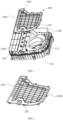
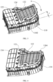
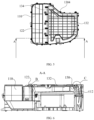
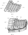
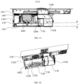
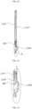
- a range hood assembly and an integrated cooker according to some embodiments of the present disclosure are described below with reference to FIG. 1 to FIG. 36 .
- an embodiment of the present disclosure provides a range hood assembly 100, and the range hood assembly 100 comprises: a volute 110, wherein the end face of the volute 110 comprises an opening 1102; a buckling part 120, arranged on the end face of the volute 110 and located on the first side of the opening 1102; a bottom plate 130 covering the opening 1102, wherein the bottom plate 130 comprises a first side edge 1302 and a through hole 1304, the buckling part 120 is buckled to the first side edge 1302, and the through hole 1304 avoids the first side edge 1302 in the circumferential direction of the bottom plate 130; and a connecting piece 140 penetrating through the through hole 1304 and connected to the volute 110.
- the present disclosure defines a range hood assembly 100, and the range hood assembly 100 is used for an integrated cooker 200 and can meet the need of sucking oil fume of the integrated cooker 200.
- the range hood assembly 100 comprises the volute 110 and the bottom plate 130, the volute 110 is the main frame structure of the range hood assembly 100, a wind cavity for accommodating a centrifugal fan is formed inside the volute 110, the volute 110 is provided with a fume inlet and a fume outlet, after the centrifugal fan is started, oil fume is sucked into the volute 110 via the fume inlet, and is discharged via the fume outlet after being pressurized by the centrifugal fan.
- the end face of the volute 110 is provided with the opening 1102, the centrifugal fan can be mounted in the volute 110 through the opening 1102, and thus the difficulty in disassembling and assembling and maintaining the centrifugal fan is lowered.
- the oil fume includes much oil and water vapor, an oil water mixture separated from the oil fume will accumulate at the bottom of the wind cavity, through arranging the opening 1102, this portion of oil water mixture can be discharged out of the volute 110, to prevent the oil water mixture from damaging the fan, and this can prevent generating a peculiar smell due to the long-term accumulation of the oil water mixture.
- a cover plate 132 is connected to the volute 110, and after the assembling of the cover plate 132 is completed, the cover plate 132 can seal the opening 1102, and then the volute 110 is opened and closed through the cover plate 132.
- the end face of the volute 110 is provided with the buckling part 120, the buckling part 120 is located at the first side of the opening 1102, the bottom plate 130 comprises the first side edge 1302 and the through hole 1304, the first side edge 1302 corresponds to the first side of the opening 1102, the through hole 1304 corresponds to the other sides of the opening 1102 except the first side, and specifically, in the circumferential direction of the bottom plate 130, the through hole 1304 avoids the first side edge 1302, to avoid the interference of the through hole 1304 and the buckling part 120.
- the range hood assembly 100 further comprises the connecting piece 140, the connecting piece 140 penetrates through the through hole 1304 and is connected to the volute 110, to press the bottom plate 130 onto the end face of the volute 110.
- the bottom plate 130 is first inclined and the first side edge 1302 of the bottom plate 130 is buckled through the buckling part 120, and this avoids the warping of the first side edge 1302 of the bottom plate 130, to complete the initial positioning of the bottom plate 130. Then, the portion of the bottom plate 130 which does not contact the volute 110 is pressed downward towards the volute 110, and the entire bottom plate 130 is buckled at the opening 1102, and meanwhile the through hole 1304 in the bottom plate 130 is aligned with a screw hole reserved in the volute 110, and finally the connecting piece 140 is screwed into the screw hole, to press the bottom plate 130 on the volute 110 through the connecting piece 140.
- the bottom plate 130 can be locked on the volute 110 after the bottom plate 130 is subjected to buckling and initial positioning; compared with the embodiment of fixing the bottom plate 130 only through the movable latch, the connecting piece 140 can provide an enough pressing force to the bottom plate 130, firstly, this can lower the possibility that the bottom plate 130 becomes loose due to factors such as vibration, and secondly, a sealing ring 150 between the bottom plate 130 and the volute 110 is compressed tightly, and it is ensured that the sealing ring 150 can seal the gap between the bottom plate 130 and the volute 110, and thus the problems of bad sealing performance and poor reliability in the related art are solved.
- the movable latch is easily fatigue and fails and is easily broken during transportation. Furthermore, the effects are achieved that the fixing joint of the bottom plate 130 is optimized, the sealing reliability of the bottom plate 130 is improved, the complexity of the disassembling and assembling of the bottom plate 130 is lowered, and the reliability of the fixing of the bottom plate 130 is improved.
- the bottom plate 130 comprises: the cover plate 132 covering the opening 1102, wherein the through hole 1304 is located in the cover plate 132; a straight edge 134 connected to the side wall of the cover plate 132 and forming the first side edge 1302, wherein the buckling part 120 and the end face of the volute 110 enclose an inserting groove facing the straight edge 134, and the straight edge 134 is inserted into the inserting groove.
- the bottom plate 130 comprises the cover plate 132 and the straight edge 134
- the through hole 1304 is provided in the cover plate 132
- the cover plate 132 covers the opening 1102.
- the straight edge 134 is provided at the circumferential side face of the cover plate 132, the straight edge 134 extends along a straight line direction, and the straight edge 134 constitutes the first side edge 1302 of the bottom plate 130.
- constructing the first side edge 1302 through the straight edge 134 helps lower the cooperation difficulty of the cover plate 132 and the buckling part 120.
- the buckling part 120 and the end face of the volute 110 enclose the inserting groove facing the straight edge 134, during assembling, inserting the straight edge 134 into the inserting groove can complete the initial positioning of the bottom plate 130 on the volute 110.
- the inserting cooperation structure has an advantage of low disassembling and assembling difficulty and helps lower the mounting difficulty of the bottom plate 130.
- the inserting groove cooperation structure obviates the requirement for the movable disassembling and assembling of the buckling part 120, and can avoid the failure of the buckling part 120 due to frequent movable disassembling and assembling and can further avoid the breaking of the buckling part 120 due to jolt and motion during transportation.
- the effects are achieved that the joint of the bottom plate 130 and the buckling part 120 is optimized, the structure stability of the range hood assembly 100 is improved, and the assembling complexity of the range hood assembly 100 is lowered.
- the height of the inserting groove decreases gradually.
- the height of the inserting groove decreases gradually, that is, an inserting groove with a gradually narrowed size is formed, through arranging the inserting groove with a decreasing height, the straight edge 134 can be inserted into the inserting groove inclined, that is, there is an included angle (the angle is represented by ⁇ in FIG. 3 ) between the bottom plate 130 and the end face of the volute 110 when the inserting action is completed, then along the direction of the arrow a in FIG. 3 , pressing the cover plate 132 downward can buckle the cover plate 132 at the opening 1102.
- this provides convenience for the initial positioning of the bottom plate 130, and secondly, this can lower the difficulty in aligning the through hole 1304 with the reserved screw hole in the volute 110, and then the effects of optimizing the shape of the inserting groove and lowering the difficulty of inserting and mounting the bottom plate 130 are achieved.
- the buckling part 120 comprises multiple buckles 122, the multiple buckles 122 are distributed at intervals along the straight edge 134, the multiple buckles 122 and the end face of the volute 110 enclose multiple first inserting grooves 1222, and the first side edge 1302 is inserted into the multiple first inserting grooves 1222.
- the buckling part 120 comprises multiple buckles 122, the multiple buckles 122 are distributed along the straight line direction corresponding to the extending direction of the straight edge 134 at the first side of the through hole 1304, and specifically, the multiple buckles 122 are distributed at intervals in the straight line direction.
- one end of the buckles 122 extends towards the end face of the volute 110, and the other end of the buckles 122 is away from the end face of the volute 110 and extends towards the direction of the bottom plate 130, to enclose the first inserting grooves 1222 facing the straight edge 134, the multiple buckles 122 enclose the multiple first inserting grooves 1222, and inclinedly inserting the straight edge 134 into the multiple first inserting grooves 1222 can complete the initial positioning of the bottom plate 130.
- the range hood assembly 100 further comprises a reinforcing rib 1342 provided on a face of the straight edge 134 deviating from the opening 1102, and the reinforcing rib 1342 avoids the buckles 122.
- multiple reinforcing ribs 1342 are provided on the face of the straight edge 134 deviating from the opening 1102, the reinforcing ribs 1342 extend in the width direction of the straight edge 134, and arranging the reinforcing ribs 1342 can improve the structural strength of the straight edge 134 and avoid the bending and even breaking of the straight edge during inserting and buckling and fixing, and thus the effects of improving the positioning stability of the bottom plate 130 and improving the sealing performance of the bottom plate 130 are achieved.
- the reinforcing ribs 1342 are arranged to avoid the buckles 122, to stagger the reinforcing ribs 1342 and the buckles122 and then lower the possibility of the mutual interference between the buckles 122 and the reinforcing ribs 1342 during the inclined insertion into the bottom plate 130, and then the strength of the straight edge 134 and inserting convenience are both considered.
- the range hood assembly 100 further comprises a limiting rib 1344 provided on the face of the straight edge 134 deviating from the opening 1102, and there are N groups of limiting ribs 1344, two limiting ribs 1344 form one group, the N buckles 122 are disposed to correspond to the N groups of limiting ribs 1344 one by one, and the buckle 122 is inserted between two limiting ribs 1344 in the same group.
- the volute 110 is provided with N buckles 122, the N buckles 122 and the end face of the volute 110 respectively enclose N first inserting grooves 1222, and the initial positioning of the bottom plate 130 can be completed through inclinedly inserting the straight edge 134 into the N first inserting grooves 1222.
- the straight edge is further provided with N groups of limiting ribs 1344, each group of limiting ribs 1344 comprises two limiting ribs 1344, and the two limiting ribs 1344 in the same group are arranged at an interval, to enclose a limiting groove between the two limiting ribs 1344.
- N limiting grooves are arranged to correspond to the ends of the N buckles 122 one by one in the length direction of the straight edge 134, and during the inclined insertion into the bottom plate 130, the ends of the N buckles 122 are respectively inserted into the N limiting grooves.
- the movement of the buckles 122 in the length direction of the straight edge 134 can be limited through inserting cooperation, to limit the amplitude of transverse movement of the bottom plate 130 in the length direction of the straight edge 134, and then improve the precision of the initial positioning of the bottom plate 130 on the volute 110 and lower the difficulty of aligning the through hole 1304 with the reserved screw hole in the volute 110, and furthermore achieve the effects of improving the assembling precision of the bottom plate 130 and lowering the assembling complexity of the bottom plate 130.
- the buckling part 120 further comprises a snap strip 124, the snap strip 124 and the end face of the volute 110 enclose a strip-shaped second inserting groove 1242, and at least a portion of the first side edge 1302 is inserted into the second inserting groove 1242.
- the buckling part 120 comprises the snap strip 124, the snap strip 124 is provided at the first side of the opening 1102, and the extending direction of the snap strip 124 is consistent with the length direction of the straight edge 134, the first end of the snap strip 124 is connected to the end face of the volute 110 and the other end of the snap strip 124 is away from the end face of the volute 110 and extends towards the direction of the bottom plate 130, after the assembling of the snap strip 124 is completed, the strip-shaped second inserting groove 1242 is enclosed between the snap strip 124 and the end face of the volute 110, the second inserting groove 1242 faces the bottom plate 130, and the initial positioning of the bottom plate 130 can be completed by inclinedly inserting at least a portion of a first side edge 1302 into the second inserting groove 1242.
- the range hood assembly 100 further comprises a sealing ring 150 provided between the bottom plate 130 and the volute 110 and used for sealing the gap between the bottom plate 130 and the volute 110.
- the range hood assembly 100 further comprises the sealing ring 150, the sealing ring 150 is located at the inner side of the opening 1102, and the sealing ring 150 is located between the bottom plate 130 and the volute 110, after the positioning through inserting and the connecting locking of the bottom plate 130 are completed, the bottom plate 130 can press the sealing ring 150 onto the volute 110 tightly, to enable the sealing ring 150 to fill the gap between the volute 110 and the bottom plate 130 through deformation, and then prevent the oil fume and the oil water mixture from leaking to the outside via the gap between the bottom plate 130 and volute 110. Furthermore, the effects of improving the sealing effect of the range hood assembly 100 and improving the practicality and reliability of the range hood assembly 100 are achieved.
- the face of the bottom plate 130 facing the opening 1102 comprises a mounting groove 1306, and the range hood assembly 100 further comprises a snap ring 112 provided in the volute 110 and arranged opposite to the opening 1102, the sealing ring 150 is provided in the mounting groove 1306, and the end face of the snap ring 112 abuts on the sealing ring 150.
- the bottom plate 130 is provided with the mounting groove 1306, the mounting groove 1306 is located in the face of the bottom plat 130 facing the opening 1102, the shape of the mounting groove 1306 adapts to the shape of the sealing ring 150, and the positioning of the sealing ring 150 on the bottom plate 130 can be completed by snapping the sealing ring 150 into the mounting groove 1306.
- the volute 110 is provided with the snap ring 112, the end face of the snap ring 112 is arranged opposite to the opening 1102, and the shape of the snap ring 112 adapts to the shape of the sealing ring 150, after the assembling of the bottom plate 130 is completed, the end face of the snap ring 112 can abut on the sealing ring 150, to improve the sealing effect of the sealing ring 150 between the volute 110 and the bottom plate 130 through extruding the sealing ring 150, and then achieve the effect of improving the sealing reliability of the range hood assembly 100.
- the top of the volute 110 comprises an air inlet 1106, the volute 110 comprises an air duct 1104 therein, the bottom of the volute 110 is provided with the opening 1102, and the opening 1102 is opposite to the centrifugal fan 160;
- the bottom plate 130 is connected to the volute 110, and covers the opening 1102, the volute 110 and the bottom plate 130 enclose a mounting cavity 1103, the volute 110 and the bottom plate 130 comprise the mounting cavity 1103 therein, and the range hood assembly 100 further comprises the centrifugal fan 160 provided in the mounting cavity 1103, and the air intake 1602 of the centrifugal fan 160 deviates from the air inlet 1106.
- FIG. 36 shows the flow direction of the oil fume.
- the volute 110 and the bottom plate 130 constitute a first housing
- the volute 110 forms all the side walls and a portion of the bottom wall of the first housing
- the air duct 1104 is arranged in the volute 110
- the top of the volute 110 is provided with the air inlet 1106 communicating with the top end of the air duct 1104.
- the circumferential side of the air duct 1104 in the volute 110 is formed with the space of the opening 1102 in the bottom
- the bottom plate 130 is connected to the volute 110
- the bottom plate 130 covers the opening 1102 after the mounting of the bottom plate 130 is mounted, to cooperate with the volute 110 to enclose the mounting cavity 1103.
- Arranging the opening 1102 and the bottom plate 130 can provide convenience for the disassembling and assembling of the centrifugal fan 160, during disassembling and assembling, users can mount the centrifugal fan 160 inside the first housing through the opening 1102, or take out the centrifugal fan 160 that needs to be repaired or replaced through the opening 1102.
- the opening 1102 can further be available for the probing operation of a maintenance staff when the centrifugal fan 160 fails. Furthermore, the effects of lowering the assembling difficulty and maintenance difficulty of the centrifugal fan 160 are achieved.
- the range hood assembly 100 when the interior of the range hood assembly 100 needs to be cleaned, users can clean the dirt remaining on the inner surface of the bottom plate 130 after the bottom plate 130 is disassembled, and can further probe via the opening 1102 to clean the dirt remaining on the bottom wall of the volute 110, and thus this provides convenience for users to clean a first liquid storage region and a second liquid storage region, and lowers the possibility that the range hood assembly 100 generates a peculiar smell.
- the centrifugal fan 160 is provided inside the mounting cavity 1103, an axial air intake 1602 of the centrifugal fan 160faces downward and deviates from the air inlet 1106 facing upward, and the air intake 1602 and the bottom wall of the mounting cavity 1103 are arranged at an interval.
- oil fume enters the air duct 1104 via the air inlet 1106from top to bottom and flows laterally via the air duct 1104 to the region between the air intake 1602 and the bottom wall of the mounting cavity 1103, then the oil fume is sucked into the centrifugal fan 160 via the air intake 1602 and is finally discharged into an outer smoke pipe via the circumferential side of the first housing after pressurized by the centrifugal fan 160.
- the region is concaved towards the inner side of the first housing, to form a boss at the inner side of the first housing and form a groove at the outer side of the first housing.
- the side wall of the boss is provided with a drain hole which penetrates through laterally.
- the present disclosure enables the oil water mixture in the first housing to be discharged timely. Furthermore, the effects of optimizing the structure of the range hood assembly 100, improving the practicability of the range hood assembly 100 and improving users' use experience.
- the space at the inner side of the first housing can further be reasonably used, and a plugging structure for plugging the drain hole can be arranged at the inner side of the boss and does not protrude out of the bottom face of the first housing, and thus this avoids increasing the thickness of the range hood assembly 100 due to the plugging structure and ensures that the range hood assembly 100 can be placed flat in a cupboard. Furthermore, the effects of lowering the difficulty of assembling the range hood assembly 100 and providing convenience for the miniaturized design of the range hood assembly 100 are achieved.
- the integrated cooker further comprises a convex rib 170 provided on the bottom wall of the first housing, the convex rib 170 is located in the first housing, and the convex rib 170 is laterally arranged between the first boss 1307 and the second boss 1308.
- the bottom wall of the first housing is further provided with the convex rib 170, the convex rib 170 presents a strip shape, and the two ends of the convex rib 170 are connected to the side wall of the first housing.
- a first convex rib 170 is laterally arranged between the first boss 1307 and the second boss 1308, to cooperate with the bottom wall of the first housing and the side wall of the first housing to enclose a first liquid storage region and a second liquid storage region.
- the first liquid storage region is located at a first side of the first convex rib 170, the first boss 1307 is located in the first liquid storage region, the oil water mixture thrown out of the air duct 1104 or the liquid poured from the air inlet 1106 accumulates in the first liquid storage region, and the liquid in the first liquid storage region can be discharged by opening the first drain hole 1329.
- the second liquid storage region is located at a second side of a second convex rib 170, the second boss 1308 is located in the second liquid storage region, the oil water mixture dripping out of the air intake 1602 of the centrifugal fan 160 accumulates in the second liquid storage region, and the liquid in the second liquid storage region can be discharged by opening the second drain hole 1310.
- Arranging the convex rib 170 enables the partitioned storage and partitioned discharge of the liquid accumulating in the first housing, and specifically, the liquid accumulates at a relatively fast rate in the first liquid storage region, especially when there is a liquid poured into the air inlet 1106, the first liquid storage region will be quickly filled.
- the liquid when the liquid accumulates at a relatively low rate, due to the shielding of the convex rib 170, users can individually open the first drain hole 1329 to discharge the liquid in the first liquid storage region, and the operation of frequently opening the second drain hole 1310 is obviated.
- the liquid When the liquid accumulates at a relatively fast rate, the liquid crosses the convex rib 170 and flows into the second liquid storage region, to share a liquid storage pressure through the second liquid storage region. Furthermore, the effects of optimizing the structural layout of the integrated cooker and providing convenience for users to carry out a water discharging operation are achieved.
- part of the bottom wall of the volute 110 is concaved towards the interior of the air duct 1104, and a first boss 1307 is formed in the air duct 1104; the first boss 1307 is located in the air duct 1104, and the first boss 1307 comprises a first drain hole 1329.
- part of the bottom wall of the volute 110 is concaved towards the region where the air duct 1104 is located, to form the first boss 1307 at the inner side of the air duct 1104, after the first drain hole 1329 in the first boss 1307 is opened, the liquid accumulating on the bottom wall of the volute 110 can be discharged.
- Arranging the first boss 1307 can prevent the accumulation of liquid on the bottom wall of the volute 110, and prevent a peculiar smell generated due to the accumulation from directly overflowing above the range hood assembly 100 via the air inlet 1106.
- a convex rib 170 is provided on the bottom wall of the volute 110, and the excessively accumulating liquid needs to stride over the convex rib 170 and then can flow to the region above the bottom plate 130.
- part of the bottom plate 130 is concaved towards the interior of the mounting cavity 1103, and the second boss 1308 is formed in the mounting cavity 1103; the second boss 1308 is located in the mounting cavity 1103, and the second boss 1308 comprises the second drain hole 1310.
- FIG. 25 shows the flow direction of the liquid.
- part of the bottom plate 130 is concaved towards the direction of the mounting cavity 1103, to form the second boss 1308 on the inner surface of the bottom plate 130, and after the second drain hole 1310 in the second boss 1308 is opened, the liquid accumulating on the bottom plate 130 can be discharged.
- Arranging the second boss 1308 can prevent pouring the liquid excessively accumulating on the bottom plate 130 into the centrifugal fan 160, and then can play a role of protecting the centrifugal fan 160. Furthermore, the effects of improving the safety and reliability of the range hood assembly 100 and prolonging the service life of the centrifugal fan 160 are achieved.
- the range hood assembly 100 further comprises a sealing plug 180, the size of the sealing plug 180 adapts to the size of the first drain hole 1329 or the second drain hole 1310, and laterally inserting the sealing plug 180 into the first drain hole 1329 or the second drain hole 1310 can close the first drain hole 1329 or the second drain hole 1310, to stop the oil water mixture inside the first housing from leaking to the outside.
- extracting the sealing plug 180 can discharge the oil water mixture in the first housing via the first drain hole 1329 or the second drain hole 1310.
- the boss forms a groove in the outer surface of the first housing, part of the sealing plug 180 is laterally inserted into the groove, and thus the inner space of the first housing is reasonably used, and this avoids that the outward protruding of the sealing plug 180 affects the size and the flatness of the bottom face of the range hood assembly 100.
- the face of the bottom plate 130 facing the centrifugal fan 160 is the inner surface of the bottom plate 130, on the inner surface of the bottom plate 130, at least a portion of the region is concaved towards the region where the second boss 1308 is located, to enable the liquid flowing to the bottom plate 130 to gather in the region where the second boss 1308 is located and finally accumulate around the second boss 1308.
- the second drain hole 1310 is opened, the liquid accumulating around the second boss 1308 can be discharged at the first time. Therefore, firstly, a drainage rate is improved, and secondly, the possibility is lowered that the second liquid storage region has a drainage dead spot.
- the inner surface of the bottom plate 130 is arranged to be in a bell mouth shape, and the second boss 1308 is arranged in the central region of the bell mouth, to enable the liquid around the second boss 1308 to gather near the second boss 1308 by itself.
- the face of the bottom plate 130 facing the centrifugal fan 160 comprises a drain channel 1142; and the drain channel 1142 presents a ring shape, and the second boss 1308 is located in the drain channel 1142.
- the inner surface of the bottom plate 130 is provided with the drain channel 1142.
- the drain channel 1142 presents a ring shape, and the drain channel 1142 attaches to the margin of the bottom plate 130 and extends, the second boss 1308 is provided in the drain channel 1142, the oil water mixture dripping via the air intake 1602 of the centrifugal fan 160 diffuses from the central region of the inner surface of the bottom plate 130 towards the surrounding drain channel 1142 and finally accumulate in the drain channel 1142, and the oil water mixture striding over the convex rib 170 directly flows into the drain channel 1142. After the second drain hole 1310 is opened, the oil water mixture in the drain channel 1142 can be discharged out of the first housing.
- Arranging the drain channel 1142 can centralizedly store the oil water mixture, and make the oil water mixture avoid in the horizontal direction the air intake 1602 above it and lower the possibility that oil gas and water vapor erode the centrifugal fan 160, and meanwhile, the drain channel 1142 can further play a role of collecting tough dirt and thus lower the cleaning difficulty of the bottom plate 130.
- the bottom face of the drain channel 1142 is the first bevel face 1144, and the first bevel face 1144 is inclined towards the direction of the second boss 1308; the range of the inclined angle of the first bevel face 1144 is greater than or equal to 0.2° and less than or equal to 5°.
- the bottom face of the drain channel 1142 is constructed to be first bevel face 1144, wherein the first bevel face 1144 is inclined towards the direction of the second boss 1308, that is, the region away from the second boss 1308 is relatively high, and the region close to the second boss 1308 is relatively low, to enable the oil water mixture in the drain channel 1142 to flow to the second boss 1308 along the first bevel face 1144, and ensure discharging the oil water mixture in the second liquid storage region timely.
- the inclined angles ⁇ 1 and ⁇ 2 of the first bevel face 1144 are greater than or equal to 0.2°, through limiting the inclined angle to be greater than or equal to 0.2°, it can be ensured that the first bevel face 1144 can guide the oil water mixture to the second boss 1308, and this lowers the possibility that the oil water mixture accumulates and cannot be discharged. Meanwhile, the inclined angle of the first bevel face 1144 is less than or equal to 5°, through limiting the inclined angle to be less than or equal to 5°, this can prevent the first bevel face 1144 from excessively occupying a liquid storage space, to improve the liquid storage capacity of the first liquid storage region.
- the bottom plate 130 comprises: a plate piece 1145, wherein the second boss 1308 is formed on the plate piece 1145; a protruding part 1146 provided on the face of the plate piece 1145 facing the centrifugal fan 160; a surrounding edge 1147 provided on the plate piece 1145 and surrounding the protruding part 1146, wherein the surrounding edge 1147 and the protruding part 1146 enclose the drain channel 1142.
- the bottom plate 130 comprises the plate piece 1145, the protruding part 1146 and the surrounding edge 1147.
- the plate piece 1145 is embedded at the opening 1102 of the bottom of the volute 110 and is used for closing the opening 1102.
- the face of the plate piece 1145 facing the centrifugal fan 160 is an upper surface
- the protruding part 1146 is arranged in the central region of the upper surface
- the surrounding edge 1147 is further arranged on the upper surface
- the surrounding edge 1147 surrounds the circumferential side of the protruding part 1146
- the surrounding edge 1147 and the protruding part 1146 is arranged at an interval, to enclose a ring-shaped drain channel 1142 between the protruding part 1146 and the surrounding edge 1147.
- the protruding part 1146 can play a role of guiding the oil water mixture, and the oil water mixture dripping onto the protruding part 1146 diffuses all around to the drain channel 1142, to avoid the accumulation of the oil water mixture in the region below the air intake 1602.
- the surrounding edge 1147 can play a role of stopping the oil water mixture, to lower the possibility that the oil water mixture leaks from the assembling gap between the plate piece 1145 and the volute 110.
- the bottom plate 130 further comprises a strengthening rib 1148 provided on the face of the plate piece 1145 facing the centrifugal fan 160.
- the upper surface of the plate piece 1145 is further provided with the strengthening rib 1148, and the strengthening rib 1148 is arranged laterally; arranging the strengthening rib 1148 can play a role of enhancing the structural strength of the bottom plate 130, lower the possibility that the bottom plate 130 deforms or is even damaged due to the oil water mixture accumulating above it, and thus achieve the effects of improving the structural stability of the bottom plate 130 and lowering the failure rate of the range hood assembly 100.
- the strengthening rib 1148 crosses the surrounding edge 1147, the strengthening rib 1148 comprises a via hole 1149, and the via hole 1149 is located in the drain channel 1142.
- the strengthening rib 1148 crosses the surrounding edge 1147, that is, part of the strengthening rib 1148 extends into the drain channel 1142, on this basis, the via hole 1149 penetrating through the strengthening rib 1148 is provided in the strengthening rib 1148 located in the drain channel 1142, to ensure that the oil water mixture in the drain channel 1142 will not be stopped by the strengthening rib 1148.
- the range hood assembly 100 further comprises a marking part 190 provided on the bottom plate 130 and/or the volute 110, in the radial direction of the volute 110, the marking part 190 is arranged opposite to the boss, and the marking part 190 is used to indicate the position of the boss.
- the bottom plate 130 and/or the volute 110 is provided with the marking part 190, the marking part 190 and the protruding part 1146 are arranged opposite to each other in the radial direction of the volute 110, the marking part 190 has a marking function, users can determine the position of the boss on the volute 110 through the marking part 190 and thus can quickly find the boss, and this provides convenience for users to open and close the drain holes and improves users' use experience.
- the marking part 190 can be an arrow-shaped protrusion, and the direction of the arrow is consistent with the position of the first boss 1307.
- the marking part 190 can further be a luminescent piece, and users can quickly determine the position of the boss through emitted light.
- the marking part 190 can further be a fluorescent coating to improve the recognition of the corresponding region.
- the face where the air intake 1602 is located is the second bevel face 1604, and the second bevel face 1604 is inclined towards the direction of the air inlet 1106; the range of the inclined angle of the second bevel face 1604 is greater than or equal to 1° and less than or equal to 30°.
- the face of the centrifugal fan 160 forming the air intake 1602 is constructed to be the second bevel face 1604, the second bevel face 1604 is inclined towards the direction of the air inlet 1106, that is, the region close to the air inlet 1106 is relatively high and the region away from the air inlet 1106 is relatively low.
- the oil fume sucked from the air inlet 1106 first flows in the air duct 1104 from top to bottom, and then turns around and flows into the air intake 1602 from bottom to top, in this regard, through arranging the second bevel face 1604 in the region where the air intake 1602 is located, the angle that the oil fume turns around can be reduced, thus the resistance to the oil fume in the first housing is reduced, and then the effects of improving the oil fume sucking efficiency of the range hood assembly 100 and optimizing the performance of the range hood assembly 100 are achieved.
- the inclined angle ⁇ of the second bevel face 1604 is greater than or equal to 1°, to ensure that the second bevel face 1604 can effectively lower the resistance to the oil fume and improve the oil fume sucking efficiency. Meanwhile, the inclined angle of the second bevel face 1604 is less than or equal to 30°, to prevent the second bevel face 1604 from excessively occupying the inner space of the volute 110, and reduce the thickness of the range hood assembly 100 on the basis of ensuring the oil fume sucking efficiency.
- an embodiment of the present disclosure provides an integrated cooker 200, and the integrated cooker 200 comprises: a heating assembly 210; the range hood assembly 100 in any of the above embodiments, wherein a volute 110 is connected to the heating assembly 210, and the volute 110 comprises a fume outlet; and a smoke pipe assembly 220 in butt joint with the fume outlet.
- the integrated cooker 200 provided with the range hood assembly 100 in any of the above embodiments is defined, and thus the integrated cooker 200 has all the advantages of the range hood assembly 100 in any of the above embodiments and can achieve the effect that the range hood assembly 100 in any of the above embodiments can achieve, which is not detailed herein for avoiding repetition.
- the integrated cooker 200 further comprises the heating assembly 210 and the smoke pipe assembly 220, the top of the heating assembly 210 is provided with a fume inlet, the heating assembly 210 is provided with a first air duct communicating with the fume inlet therein, the range hood assembly 100 is mounted below the heating assembly 210, the fume outlet is provided at the circumferential side of the range hood assembly 100, and the range hood assembly 100 is formed with a second air duct communicating with the first air duct and the fume outlet therein.
- the heating assembly 210 can heat a top container, to cook foods placed therein through a high temperature container. Oil fume and water vapor will be generated during high temperature heating to foods, after the range hood assembly 100 is limited to start, a negative pressure is generated in the first air duct, the oil fume is sucked into the second air duct through the fume inlet and the first air duct, and is finally discharged into the smoke pipe assembly 220 via the fume outlet, and therefore the sucking and directional discharge of the oil fume are achieved.
Landscapes
- Engineering & Computer Science (AREA)
- Mechanical Engineering (AREA)
- General Engineering & Computer Science (AREA)
- Chemical & Material Sciences (AREA)
- Combustion & Propulsion (AREA)
- Ventilation (AREA)
- Superstructure Of Vehicle (AREA)
Abstract
Description
- The present disclosure claims priority to
Chinese Patent Application No. 202320686553.1 filed with China National Intellectual Property Administration on March 31, 2023 - The present disclosure claims priority to
Chinese Patent Application No. 202320686354.0 filed with China National Intellectual Property Administration on March 31, 2023 - The present disclosure relates to the field of range hoods, and particularly relates to a range hood assembly and an integrated cooker.
- A range hood and cooker all-in-one machine has a downdraft range hood oil fume sucking device, wherein the range hood oil fume sucking device needs a sealing cavity and then can ensure a larger static pressure to enable oil fume to enter from a fume sucking mouth. At this moment, the assembling of a detachable bottom cover plate and a fan volute should meet sealing and should also meet convenient disassembling.
- In a related art, the bottom cover plate is fixed through a fully movable latch, the advantage of the locking of the fully movable latch is being convenient and fast, and work hours are reduced; as the bottom cover plate and the volute need a sealing ring, the sealing ring has a certain elasticity, the extruding force of the latch has a case of being unable to tightly compress the sealing ring, this results in bad sealing performance and poor reliability, and meanwhile, the movable latch easily fails due to repeated disassembling and assembling actions, and is also easily broken due to vibration during transportation.
- Therefore, how to overcome the above defects has become a problem that needs to be solved urgently.
- The present disclosure aims to solve at least one of the problems that exist in the prior art.
- To this end, the first aspect of the present disclosure provide a range hood assembly.
- The second aspect of the present disclosure provides an integrated cooker.
- In view of this, the first aspect of the present disclosure provides a rang hood assembly, and the range hood assembly comprises: a volute, wherein the end face of the volute comprises an opening; a buckling part, arranged on the end face of the volute and located on the first side of the opening; a bottom plate covering the opening, wherein the bottom plate comprises a first side edge and a through hole, the buckling part is buckled to the first side edge, and the through hole avoids the first side edge in the circumferential direction of the bottom plate; and a connecting piece penetrating through the through hole and connected to the volute.
- The present disclosure defines a range hood assembly, and the range hood assembly is used for an integrated cooker and can meet the need of sucking oil fume of the integrated cooker. The range hood assembly comprises the volute and the bottom plate, the volute is the main frame structure of the range hood assembly, a wind cavity for accommodating a centrifugal fan is formed inside the volute, the volute is provided with a fume inlet and a fume outlet, after the centrifugal fan is started, oil fume is sucked into the volute via the fume inlet, and is discharged via the fume outlet after being pressurized by the centrifugal fan.
- Wherein, the end face of the volute is provided with the opening, the centrifugal fan can be mounted in the volute through the opening, and thus the difficulty in disassembling and assembling and maintaining the centrifugal fan is lowered. During working, the oil fume includes much oil and water vapor, an oil water mixture separated from the oil fume will accumulate at the bottom of the wind cavity, through arranging the opening, this portion of oil water mixture can be discharged out of the volute, to prevent the oil water mixture from damaging the fan, and this can prevent generating a peculiar smell due to the long-term accumulation of the oil water mixture. A cover plate is connected to the volute, and after the assembling of the cover plate is completed, the cover plate can seal the opening, and then the volute is opened and closed through the cover plate.
- On the above basis, the end face of the volute is provided with the buckling part, the buckling part is located at the first side of the opening, the bottom plate comprises the first side edge and the through hole, the first side edge corresponds to the first side of the opening, the through hole corresponds to the other sides of the opening except the first side, and specifically, in the circumferential direction of the bottom plate, the through hole avoids the first side edge, to avoid the interference of the through hole and the buckling part. The range hood assembly further comprises the connecting piece, the connecting piece penetrates through the through hole and is connected to the volute, to press the bottom plate onto the end face of the volute.
- Specifically, during mounting the bottom plate, the bottom plate is first inclined and the first side edge of the bottom plate is buckled through the buckling part, and this avoids the warping of the first side edge of the bottom plate, to complete the initial positioning of the bottom plate. Then, the portion of the bottom plate which does not contact the volute is pressed downward towards the volute, and the entire bottom plate is buckled at the opening, and meanwhile the through hole in the bottom plate is aligned with a screw hole reserved in the volute, and finally the connecting piece is screwed into the screw hole, to press the bottom plate on the volute through the connecting piece.
- Through arranging the through hole and the connecting piece cooperating with the buckling part, the bottom plate can be locked on the volute after the bottom plate is subjected to buckling and initial positioning; compared with the embodiment of fixing the bottom plate only through the movable latch, the connecting piece can provide an enough pressing force to the bottom plate, firstly, this can lower the possibility that the bottom plate becomes loose due to factors such as vibration, and secondly, a sealing ring between the bottom plate and the volute is compressed tightly, and it is ensured that the sealing ring can seal the gap between the bottom plate and the volute, and thus the problems of bad sealing performance and poor reliability in the related art are solved. Meanwhile, due to the existence of the through hole, the requirement for the movable disassembling and assembling of the buckling part is obviated, thus the problems in the prior art are solved that the movable latch is easily fatigue and fails and is easily broken during transportation. Furthermore, the effects are achieved that the fixing joint of the bottom plate is optimized, the sealing reliability of the bottom plate is improved, the complexity of the disassembling and assembling of the bottom plate is lowered, and the reliability of the fixing of the bottom plate is improved.
- In addition, the above range hood assembly provided in the present disclosure can further comprise following additional features.
- In the above embodiment, the bottom plate comprises: the cover plate covering the opening, wherein the through hole is located in the cover plate; a straight edge connected to the side wall of the cover plate and forming the first side edge, wherein the buckling part and the end face of the volute enclose an inserting groove facing the straight edge, and the straight edge is inserted into the inserting groove.
- In the embodiment, the bottom plate comprises the cover plate and the straight edge, the through hole is provided in the cover plate, after the assembling of the bottom plate is completed, the cover plate covers the opening. The straight edge is provided at the circumferential side face of the cover plate, the straight edge extends along a straight line direction, and the straight edge constitutes the first side edge of the bottom plate. Compared with the embodiment of forming the first side edge through a curved edge, constructing the first side edge through the straight edge helps lower the cooperation difficulty of the cover plate and the buckling part.
- On this basis, the buckling part and the end face of the volute enclose the inserting groove facing the straight edge, during assembling, inserting the straight edge into the inserting groove can complete the initial positioning of the bottom plate on the volute. The inserting cooperation structure has an advantage of low disassembling and assembling difficulty and helps lower the mounting difficulty of the bottom plate. Meanwhile, the inserting groove cooperation structure obviates the requirement for the movable disassembling and assembling of the buckling part, and can avoid the failure of the buckling part due to frequent movable disassembling and assembling and can further avoid the breaking of the buckling part due to jolt and motion during transportation. Furthermore, the effects are achieved that the joint of the bottom plate and the buckling part is optimized, the structure stability of the range hood assembly is improved, and the assembling complexity of the range hood assembly is lowered.
- In any of the above embodiments, in the depth direction of the inserting groove, the height of the inserting groove decreases gradually.
- In the embodiment, in the depth direction of the inserting groove, the height of the inserting groove decreases gradually, that is, an inserting groove with a gradually narrowed size is formed, through arranging the inserting groove with a decreasing height, the straight edge can be inserted into the inserting groove inclined, that is, there is an included angle between the bottom plate and the end face of the volute when the inserting action is completed, then pressing the cover plate downward can buckle the cover plate at the opening. Thus, firstly, this provides convenience for the initial positioning of the bottom plate, and secondly, this can lower the difficulty in aligning the through hole with the reserved screw hole in the volute, and then the effects of optimizing the shape of the inserting groove and lowering the difficulty of inserting and mounting the bottom plate are achieved.
- In any of the above embodiments, the buckling part comprises multiple buckles, the multiple buckles are distributed at intervals along the straight edge, the multiple buckles and the end face of the volute enclose multiple first inserting grooves, and the first side edge is inserted into the multiple first inserting grooves.
- In the embodiment, the buckling part comprises multiple buckles, the multiple buckles are distributed along the straight line direction corresponding to the extending direction of the straight edge at the first side of the through hole, and specifically, the multiple buckles are distributed at intervals in the straight line direction. Wherein, one end of the buckles extends towards the end face of the volute, and the other end of the buckles is away from the end face of the volute and extends towards the direction of the bottom plate, to enclose the first inserting grooves facing the straight edge, the multiple buckles enclose the multiple first inserting grooves, and inclinedly inserting the straight edge into the multiple first inserting grooves can complete the initial positioning of the bottom plate.
- Through arranging multiple buckles to cooperate with buckling the straight edge, this helps improve the buckling stability of the buckling part to the straight edge, avoids the warping of the bottom plate during working due to factors such as vibration, and ensures that the buckling part can cooperate with the connecting piece to tightly press the bottom plate on the volute. Furthermore, the effects of optimizing the structure of the buckling part and improving the structure stability and sealing reliability of the bottom plate are achieved.
- In any of the above embodiments, the range hood assembly further comprises a reinforcing rib provided on a face of the straight edge deviating from the opening, and the reinforcing rib avoids the buckles.
- In the embodiment, multiple reinforcing ribs are provided on the face of the straight edge deviating from the opening, the reinforcing ribs extend in the width direction of the straight edge, and arranging the reinforcing ribs can improve the structural strength of the straight edge and avoid the bending and even breaking of the straight edge during inserting and buckling and fixing, and thus the effects of improving the positioning stability of the bottom plate and improving the sealing performance of the bottom plate are achieved.
- Specifically, in the length direction of the straight edge, the reinforcing ribs are arranged to avoid the buckles, to stagger the reinforcing ribs and the buckles and then lower the possibility of the mutual interference between the buckles and the reinforcing ribs during the inclined insertion into the bottom plate, and then the strength of the straight edge and inserting convenience are both considered.
- In any of the above embodiments, there are N buckles, and the range hood assembly further comprises a limiting rib provided on the face of the straight edge deviating from the opening, and there are N groups of limiting ribs, two limiting ribs form one group, the N buckles are disposed to correspond to the N groups of limiting ribs one by one, and the buckle is inserted between two limiting ribs in the same group.
- In the embodiment, the volute is provided with N buckles, the N buckles and the end face of the volute respectively enclose N first inserting grooves, and the initial positioning of the bottom plate can be completed through inclinedly inserting the straight edge into the N first inserting grooves. On this basis, the straight edge is further provided with N groups of limiting ribs, each group of limiting ribs comprises two limiting ribs, and the two limiting ribs in the same group are arranged at an interval, to enclose a limiting groove between the two limiting ribs. Wherein, N limiting grooves are arranged to correspond to the ends of the N buckles one by one in the length direction of the straight edge, and during the inclined insertion into the bottom plate, the ends of the N buckles are respectively inserted into the N limiting grooves.
- Through arranging the limiting ribs, the movement of the buckles in the length direction of the straight edge can be limited through inserting cooperation, to limit the amplitude of transverse movement of the bottom plate in the length direction of the straight edge, and then improve the precision of the initial positioning of the bottom plate on the volute and lower the difficulty of aligning the through hole with the reserved screw hole in the volute, and furthermore achieve the effects of improving the assembling precision of the bottom plate and lowering the assembling complexity of the bottom plate.
- In any of the above embodiments, the buckling part further comprises a snap strip, the snap strip and the end face of the volute enclose a strip-shaped second inserting groove, and at least a portion of the first side edge is inserted into the second inserting groove.
- In the embodiment, the buckling part comprises the snap strip, the snap strip is provided at the first side of the opening, and the extending direction of the snap strip is consistent with the length direction of the straight edge, the first end of the snap strip is connected to the end face of the volute and the other end of the snap strip is away from the end face of the volute and extends towards the direction of the bottom plate, after the assembling of the snap strip is completed, the strip-shaped second inserting groove is enclosed between the snap strip and the end face of the volute, the second inserting groove faces the bottom plate, and the initial positioning of the bottom plate can be completed by inclinedly inserting at least a portion of a first side edge into the second inserting groove.
- Through arranging the strip-shaped snap strip to cooperate with buckling the straight edge, this helps improve the buckling stability of the buckling part to the straight edge, avoids the warping of the bottom plate during working due to factors such as vibration, and ensures that the buckling part can cooperate with the connecting piece to tightly press the bottom plate on the volute. Furthermore, the effects of optimizing the structure of the buckling part and improving the structure stability and sealing reliability of the bottom plate are achieved.
- In any of the above embodiments, the range hood assembly further comprises a sealing ring provided between the bottom plate and the volute and used for sealing the gap between the bottom plate and the volute.
- In the embodiment, the range hood assembly further comprises the sealing ring, the sealing ring is located at the inner side of the opening, and the sealing ring is located between the bottom plate and the volute, after the initial positioning through inserting and the connecting locking of the bottom plate are completed, the bottom plate can press the sealing ring onto the volute tightly, to enable the sealing ring to fill the gap between the volute and the bottom plate through deformation, and then prevent the oil fume and the oil water mixture from leaking to the outside via the gap between the bottom plate and volute. Furthermore, the effects of improving the sealing effect of the range hood assembly and improving the practicality and reliability of the range hood assembly are achieved.
- In any of the above embodiments, the face of the bottom plate facing the opening comprises a mounting groove, and the range hood assembly further comprises a snap ring provided in the volute and arranged opposite to the opening, the sealing ring is provided in the mounting groove, and the end face of the snap ring abuts on the sealing ring.
- In the embodiment, the bottom plate is provided with the mounting groove, the mounting groove is located in the face of the bottom plate facing the opening, the shape of the mounting groove adapts to the shape of the sealing ring, and the positioning of the sealing ring on the bottom plate can be completed by snapping the sealing ring into the mounting groove. On this basis, the volute is provided with the snap ring, the end face of the snap ring is arranged opposite to the opening, and the shape of the snap ring adapts to the shape of the sealing ring, after the assembling of the bottom plate is completed, the end face of the snap ring can abut on the sealing ring, to improve the sealing effect of the sealing ring between the volute and the bottom plate through extruding the sealing ring, and then achieve the effect of improving the sealing reliability of the range hood assembly.
- In any of the above embodiments, the top of the volute comprises an air inlet, the volute comprises an air duct therein, the bottom of the volute is provided with the opening, and the opening is opposite to the centrifugal fan; the bottom plate is connected to the volute, and covers the opening, the volute and the bottom plate enclose a mounting cavity, the volute and the bottom plate comprise the mounting cavity therein, and the range hood assembly further comprises the centrifugal fan provided in the mounting cavity, and the air intake of the centrifugal fan deviates from the air inlet.
- In the embodiment, the volute and the bottom plate constitute a first housing, the volute forms all the side walls and a portion of the bottom wall of the first housing, the air duct is arranged in the volute, and the top of the volute is provided with the air inlet communicating with the top end of the air duct. The circumferential side of the air duct in the volute is formed with the space of the opening in the bottom, the bottom plate is connected to the volute, and the bottom plate covers the opening after the mounting of the bottom plate is mounted, to cooperate with the volute to enclose the mounting cavity.
- Arranging the opening and the bottom plate can provide convenience for the disassembling and assembling of the centrifugal fan, during disassembling and assembling, users can mount the centrifugal fan inside the first housing through the opening, or take out the centrifugal fan that needs to be repaired or replaced through the opening. The opening can be available for the probing operation of a maintenance staff when the centrifugal fan fails. Furthermore, the effects of lowering the assembling difficulty and maintenance difficulty of the centrifugal fan are achieved.
- Specifically, when the interior of the range hood assembly needs to be cleaned, users can clean the dirt remaining on the inner surface of the bottom plate after the bottom plate is disassembled, and can further probe via the opening to clean the dirt remaining on the bottom wall of the volute, and thus this provides convenience for users to clean a first liquid storage region and a second liquid storage region, and lowers the possibility that the range hood assembly generates a peculiar smell.
- The centrifugal fan is provided inside the mounting cavity, an axial air intake of the centrifugal fan faces downward and deviates from the air inlet facing upward, and the air intake and the bottom wall of the mounting cavity are arranged at an interval. After the centrifugal fan is started, oil fume enters the air duct via the air inlet from top to bottom and flows laterally via the air duct to the region between the air intake and the bottom wall of the mounting cavity, then the oil fume is sucked into the centrifugal fan via the air intake and is finally discharged into an outer smoke pipe via the circumferential side of the first housing after pressurized by the centrifugal fan. Wherein, as the oil fume needs to change direction before it is sucked into the centrifugal fan, part of oil and water will be thrown to the bottom wall of the first housing, even if the oil fume is sucked into the centrifugal fan, the oil and water adhering to the interior of the centrifugal fan will further drip to the bottom wall of the first housing via the air intake after the centrifugal fan stops, and furthermore, as the air inlet is opened in the top of the first housing, the water on the countertop of the range hood assembly will be poured into the first housing directly via the air inlet, and this finally results in the accumulation of huge oil water mixture in the first housing.
- On this basis, on the bottom wall of the first housing, at least a portion of the region is concaved towards the inner side of the first housing, to form a boss at the inner side of the first housing and form a groove at the outer side of the first housing. Wherein, the side wall of the boss is provided with a drain hole which penetrates through laterally. Through arranging the boss, the oil water mixture accumulating on the bottom wall of the first housing can laterally flow out of the first housing via the drain hole, and specifically, as the oil water mixture has certain viscosity, the oil water mixture previously flowing out of the drain hole will bring the oil water mixture in the first housing to flow out, and thus the oil water mixture in the first housing is emptied, to meet the need of discharging the liquid inside the first housing, prevent the oil water mixture excessively accumulating in the first housing from damaging other electrical structures, and avoid generating peculiar smells in the first housing.
- Thus it can be seen that through constructing the boss and the drain hole on the bottom wall of the first housing, the present disclosure enables the oil water mixture in the first housing to be discharged timely. Furthermore, the effects of optimizing the structure of the range hood assembly, improving the practicability of the range hood assembly and improving users' use experience.
- Specifically, through constructing an inner-concave boss, the space at the inner side of the first housing can further be reasonably used, and a plugging structure for plugging the drain hole can be arranged at the inner side of the boss and does not protrude out of the bottom face of the first housing, and thus this avoids increasing the thickness of the range hood assembly due to the plugging structure and ensures that the range hood assembly can be placed flat in a cupboard. Furthermore, the effects of lowering the difficulty of assembling the range hood assembly and providing convenience for the miniaturized design of the range hood assembly are achieved.
- In any of the above embodiments, part of the bottom wall of the volute is concaved towards the interior of the air duct, and a first boss is formed in the air duct; the first boss is located in the air duct, and the first boss comprises a first drain hole; part of the bottom plate is concaved towards the interior of the mounting cavity, and a second boss is formed in the mounting cavity; the second boss is located in the mounting cavity, and the second boss comprises a second drain hole; wherein, on the face of the bottom plate facing the centrifugal fan, at least a portion of the region except the second boss is concaved towards the second boss.
- In the embodiment, part of the bottom wall of the volute is concaved towards the region where the air duct is located, to form the first boss at the inner side of the air duct, after the first drain hole in the first boss is opened, the liquid accumulating on the bottom wall of the volute can be discharged. Arranging the first boss can prevent the accumulation of liquid on the bottom wall of the volute, and prevent a peculiar smell generated due to the accumulation from directly overflowing above the range hood assembly via the air inlet.
- Specifically, a convex rib is provided on the bottom wall of the volute, and the excessively accumulating liquid needs to stride over the convex rib and then can flow to the region above the bottom plate.
- In the embodiment, part of the bottom plate is concaved towards the direction of the mounting cavity, to form the second boss on the inner surface of the bottom plate, and after the second drain hole in the second boss is opened, the liquid accumulating on the bottom plate can be discharged. Arranging the second boss can prevent pouring the liquid excessively accumulating on the bottom plate into the centrifugal fan, and then can play a role of protecting the centrifugal fan. Furthermore, the effects of improving the safety and reliability of the range hood assembly and prolonging the service life of the centrifugal fan are achieved.
- Specifically, the range hood assembly further comprises a sealing plug, the size of the sealing plug adapts to the size of the first drain hole or the second drain hole, and laterally inserting the sealing plug into the first drain hole or the second drain hole can close the first drain hole or the second drain hole, to stop the oil water mixture inside the first housing from leaking to the outside. Correspondingly, extracting the sealing plug can discharge the oil water mixture in the first housing via the first drain hole or the second drain hole.
- Specifically, the boss forms a groove in the outer surface of the first housing, part of the sealing plug is laterally inserted into the groove, and thus the inner space of the first housing is reasonably used, and this avoids that the outward protruding of the sealing plug affects the size and the flatness of the bottom face of the range hood assembly.
- In the embodiment, the face of the bottom plate facing the centrifugal fan is the inner surface of the bottom plate, on the inner surface of the bottom plate, at least a portion of the region is concaved towards the region where the second boss is located, to enable the liquid flowing to the bottom plate to gather in the region where the second boss is located and finally accumulate around the second boss. After the second drain hole is opened, the liquid accumulating around the second boss can be discharged at the first time. Therefore, firstly, a drainage rate is improved, and secondly, the possibility is lowered that the second liquid storage region has a drainage dead spot.
- Specifically, the inner surface of the bottom plate is arranged to be in a bell mouth shape, and the second boss is arranged in the central region of the bell mouth, to enable the liquid around the second boss to gather near the second boss by itself.
- In any of the above embodiments, the face of the bottom plate facing the centrifugal fan comprises a drain channel; and
the drain channel presents a ring shape, and the second boss is located in the drain channel. Wherein, the bottom face of the drain channel is a first bevel face, and the first bevel face is inclined towards the direction of the second boss; and the range of the inclined angle of the first bevel face is greater than or equal to 0.2° and less than or equal to 5°. - In the embodiment, the inner surface of the bottom plate is provided with the drain channel. Specifically, the drain channel presents a ring shape, and the drain channel attaches to the margin of the bottom plate and extends, the second boss is provided in the drain channel, the oil water mixture dripping via the air intake of the centrifugal fan diffuses from the central region of the inner surface of the bottom plate towards the surrounding drain channel and finally accumulate in the drain channel, and the oil water mixture striding over the convex rib directly flows into the drain channel. After the second drain hole is opened, the oil water mixture in the drain channel can be discharged out of the first housing. Arranging the drain channel can centralizedly store the oil water mixture, and make the oil water mixture avoid in the horizontal direction the air intake above it and lower the possibility that oil gas and water vapor erode the centrifugal fan, and meanwhile, the drain channel can further play a role of collecting tough dirt and thus lower the cleaning difficulty of the bottom plate.
- In the embodiment, the bottom face of the drain channel is constructed to be first bevel face, wherein the first bevel face is inclined towards the direction of the second boss, that is, the region away from the second boss is relatively high, and the region close to the second boss is relatively low, to enable the oil water mixture in the drain channel to flow to the second boss along the first bevel face, and ensure discharging the oil water mixture in the second liquid storage region timely.
- On this basis, the inclined angle of the first bevel face is greater than or equal to 0.2°, through limiting the inclined angle to be greater than or equal to 0.2°, it can be ensured that the first bevel face can guide the oil water mixture to the second boss, and this lowers the possibility that the oil water mixture accumulates and cannot be discharged. Meanwhile, the inclined angle of the first bevel face is less than or equal to 5°, through limiting the inclined angle to be less than or equal to 5°, this can prevent the first bevel face from excessively occupying a liquid storage space, to improve the liquid storage capacity of the first liquid storage region.
- In any of the above embodiments, the bottom plate comprises: a plate piece, wherein the second boss is formed on the plate piece; a protruding part provided on the face of the plate piece facing the centrifugal fan; a surrounding edge provided on the plate piece and surrounding the protruding part, wherein the surrounding edge and the protruding part enclose the drain channel; the reinforcing rib provided on the face of the plate piece facing the centrifugal fan; wherein, the reinforcing rib crosses the surrounding edge, the reinforcing rib comprises a through hole, and the through hole is located in the drain channel.
- In the embodiment, the bottom plate comprises the plate piece, the protruding part and the surrounding edge. The plate piece is embedded at the opening of the bottom of the volute and is used for closing the opening. The face of the plate piece facing the centrifugal fan is an upper surface, the protruding part is arranged in the central region of the upper surface, the surrounding edge is further arranged on the upper surface, the surrounding edge surrounds the circumferential side of the protruding part, and the surrounding edge and the protruding part is arranged at an interval, to enclose a ring-shaped drain channel between the protruding part and the surrounding edge.
- The protruding part can play a role of guiding the oil water mixture, and the oil water mixture dripping onto the protruding part diffuses all around to the drain channel, to avoid the accumulation of the oil water mixture in the region below the air intake. The surrounding edge can play a role of stopping the oil water mixture, to lower the possibility that the oil water mixture leaks from the assembling gap between the plate piece and the volute.
- In the embodiment, the upper surface of the plate piece is further provided with the reinforcing rib, and the reinforcing rib is arranged laterally; arranging the reinforcing rib can play a role of enhancing the structural strength of the bottom plate, lower the possibility that the bottom plate deforms or is even damaged due to the oil water mixture accumulating above it, and thus achieve the effects of improving the structural stability of the bottom plate and lowering the failure rate of the range hood assembly.
- In the embodiment, the reinforcing rib crosses the surrounding edge, that is, part of the reinforcing rib extends into the drain channel, on this basis, the through hole penetrating through the reinforcing rib is provided in the reinforcing rib located in the drain channel, to ensure that the oil water mixture in the drain channel will not be stopped by the reinforcing rib.
- In any of the above embodiments, the range hood assembly further comprises a marking part provided on the bottom plate and/or the volute, in the radial direction of the volute, the marking part is arranged opposite to the boss, and the marking part is used to indicate the position of the boss; wherein, on the centrifugal fan, the face where the air intake is located is a second bevel face, the second bevel face is inclined towards the direction of the air inlet; and the range of the inclined angle of the second bevel face is greater than or equal to 1° and less than or equal to 30°.
- In the embodiment, the bottom plate and/or the volute is provided with the marking part, the marking part and the protruding part are arranged opposite to each other in the radial direction of the volute, the marking part has a marking function, users can determine the position of the boss on the volute through the marking part and thus can quickly find the boss, and this provides convenience for users to open and close the drain holes and improves users' use experience.
- Specifically, the marking part can be an arrow-shaped protrusion, and the direction of the arrow is consistent with the position of the first boss. The marking part can further be a luminescent piece, and users can quickly determine the position of the boss through emitted light. The marking part can further be a fluorescent coating to improve the recognition of the corresponding region.
- In the embodiment, the face of the centrifugal fan forming the air intake is constructed to be the second bevel face, the second bevel face is inclined towards the direction of the air inlet, that is, the region close to the air inlet is relatively high and the region away from the air inlet is relatively low. During working, the oil fume sucked from the air inlet first flows in the air duct from top to bottom, and then turns around and flows into the air intake from bottom to top, in this regard, through arranging the second bevel face in the region where the air intake is located, the angle that the oil fume turns around can be reduced, thus the resistance to the oil fume in the first housing is reduced, and then the effects of improving the oil fume sucking efficiency of the range hood assembly and optimizing the performance of the range hood assembly are achieved.
- Specifically, the inclined angle of the second bevel face is greater than or equal to 1°, to ensure that the second bevel face can effectively lower the resistance to the oil fume and improve the oil fume sucking efficiency. Meanwhile, the inclined angle of the second bevel face is less than or equal to 30°, to prevent the second bevel face from excessively occupying the inner space of the volute, and reduce the thickness of the range hood assembly on the basis of ensuring the oil fume sucking efficiency.
- The second aspect of the present disclosure provides an integrated cooker, and the integrated cooker comprises: a heating assembly; the range hood assembly in any of the above embodiments, wherein a volute is connected to the heating assembly, and the volute comprises a fume outlet; and a smoke pipe assembly in butt joint with the fume outlet.
- In the embodiment, the integrated cooker provided with the range hood assembly in any of the above embodiments is defined, and thus the integrated cooker has all the advantages of the range hood assembly in any of the above embodiments and can achieve the effect that the range hood assembly in any of the above embodiments can achieve, which is not detailed herein for avoiding repetition.
- On this basis, the integrated cooker further comprises the heating assembly and the smoke pipe assembly, the top of the heating assembly is provided with a fume inlet, the heating assembly is provided with a first air duct communicating with the fume inlet therein, the range hood assembly is mounted below the heating assembly, the fume outlet is provided at the circumferential side of the range hood assembly, and the range hood assembly is formed with a second air duct communicating with the first air duct and the fume outlet therein.
- After the heating assembly is started, the heating assembly can heat a top container, to cook foods placed therein through a high temperature container. Oil fume and water vapor will be generated during high temperature heating to foods, after the range hood assembly is limited to start, a negative pressure is generated in the first air duct, the oil fume is sucked into the second air duct through the fume inlet and the first air duct, and is finally discharged into the smoke pipe assembly via the fume outlet, and therefore the sucking and directional discharge of the oil fume are achieved.
- The additional aspects and advantages of the present disclosure will become apparent in the following description, or will be understood by the practice of the present disclosure.
- The above and/or additional aspects and advantages of the present disclosure will be obvious and understood easily from the following description of the embodiments in combination with the accompanying drawings. Wherein,
-
FIG. 1 is a first schematic view of the structure of a range hood assembly according to an embodiment of the present disclosure; -
FIG. 2 is a first schematic view of the structure of a bottom plate according to an embodiment of the present disclosure; -
FIG. 3 is a second schematic view of the structure of a range hood assembly according to an embodiment of the present disclosure; -
FIG. 4 is a third schematic view of the structure of a range hood assembly according to an embodiment of the present disclosure; -
FIG. 5 is a fourth schematic view of the structure of a range hood assembly according to an embodiment of the present disclosure; -
FIG. 6 is a sectional view of the range hood assembly of the embodiment inFIG. 5 in an A-A direction; -
FIG. 7 is a partial enlarged view of the range hood assembly in the embodiment ofFIG. 6 in a region B; -
FIG. 8 is a partial enlarged view of the range hood assembly in the embodiment ofFIG. 6 in a region C; -
FIG. 9 is a second schematic view of the structure of a bottom plate according to an embodiment of the present disclosure; -
FIG. 10 is a fifth schematic view of the structure of a range hood assembly according to an embodiment of the present disclosure; -
FIG. 11 is a partial enlarged view of the range hood assembly in the embodiment ofFIG. 10 in a region D; -
FIG. 12 is a sixth schematic view of the structure of a range hood assembly according to an embodiment of the present disclosure; -
FIG. 13 is a partial enlarged view of the range hood assembly in the embodiment ofFIG. 12 in a region E; -
FIG. 14 is a seventh schematic view of the structure of a range hood assembly according to an embodiment of the present disclosure; -
FIG. 15 is a first schematic view of the structure of an integrated cooker according to an embodiment of the present disclosure; -
FIG. 16 is a partial enlarged view of the integrated cooker in the embodiment ofFIG. 15 in a region F; -
FIG. 17 is a second schematic view of the structure of an integrated cooker according to an embodiment of the present disclosure; -
FIG. 18 is a third schematic view of the structure of an integrated cooker according to an embodiment of the present disclosure; -
FIG. 19 is a sectional view of the integrated cooker of the embodiment inFIG. 18 in a G-G direction; -
FIG. 20 is a fourth schematic view of the structure of an integrated cooker according to an embodiment of the present disclosure; -
FIG. 21 is a fifth schematic view of the structure of an integrated cooker according to an embodiment of the present disclosure; -
FIG. 22 is a partial enlarged view of the integrated cooker in the embodiment ofFIG. 21 in a region H; -
FIG. 23 is a sixth schematic view of the structure of an integrated cooker according to an embodiment of the present disclosure; -
FIG. 24 is a partial enlarged view of the integrated cooker in the embodiment ofFIG. 23 in a region I; -
FIG. 25 is a seventh schematic view of the structure of an integrated cooker according to an embodiment of the present disclosure; -
FIG. 26 is an eighth schematic view of the structure of an integrated cooker according to an embodiment of the present disclosure; -
FIG. 27 is a sectional view of the integrated cooker of the embodiment inFIG. 26 in a J-J direction; -
FIG. 28 is a sectional view of the integrated cooker of the embodiment inFIG. 26 in a K-K direction; -
FIG. 29 is a ninth schematic view of the structure of an integrated cooker according to an embodiment of the present disclosure; -
FIG. 30 is a partial enlarged view of the integrated cooker in the embodiment ofFIG. 29 in a region L; -
FIG. 31 is a tenth schematic view of the structure of an integrated cooker according to an embodiment of the present disclosure; -
FIG. 32 is a partial enlarged view of the integrated cooker in the embodiment ofFIG. 31 in a region M; -
FIG. 33 is an eleventh schematic view of the structure of an integrated cooker according to an embodiment of the present disclosure; -
FIG. 34 is a partial enlarged view of the integrated cooker in the embodiment ofFIG. 33 in a region N; -
FIG. 35 is a twelfth schematic view of the structure of an integrated cooker according to an embodiment of the present disclosure; and -
FIG. 36 is a partial enlarged view of the integrated cooker in the embodiment ofFIG. 35 in a region O. - Wherein, the corresponding relationships between the reference signs and the component names in
FIG. 1 to FIG. 36 are as follows: - 100 range hood assembly; 110 volute; 1102 opening; 1103 mounting cavity; 1104 air duct; 1106 air inlet; 112 snap ring; 1142 drain channel; 1144 first bevel face; 1145 plate piece; 1146 protruding part; 1147 surrounding edge; 1148 strengthening rib; 1149 via hole; 120 buckling part; 122 buckle; 1222 first inserting groove; 124 snap strip; 1242 second inserting groove; 130 bottom plate; 1302 first side edge; 1304 through hole; 1306 mounting groove; 1307 first boss; 1308 second boss; 1329 first drain hole; 1310 second drain hole; 132 cover plate; 134 straight edge; 1342 reinforcing rib; 1344 limiting rib; 140 connecting piece; 150 sealing ring; 160 centrifugal fan; 1602 air intake; 1604 second bevel face; 170 convex rib; 180 sealing plug; 190 marking part; 200 integrated cooker; 210 heating assembly; and 220 smoke pipe assembly.
- In order to understand the above-mentioned objectives, features and advantages of the present disclosure more clearly, a further detailed description of the present disclosure will be given below in combination with the accompanying drawings and specific embodiments. It should be noted that the embodiments of the present disclosure and the features in the embodiments can be combined with each other if there is no conflict.
- In the following description, numerous specific details are set forth in order to provide a thorough understanding of the present disclosure. However, the present disclosure can further be implemented in other manners other than these described herein. Therefore, the protection scope of the present disclosure is not limited to the specific embodiments disclosed below.
- A range hood assembly and an integrated cooker according to some embodiments of the present disclosure are described below with reference to
FIG. 1 to FIG. 36 . - As shown in
FIG. 1, FIG. 2 ,FIG. 3, FIG. 4 andFIG. 8 , an embodiment of the present disclosure provides arange hood assembly 100, and therange hood assembly 100 comprises: avolute 110, wherein the end face of thevolute 110 comprises anopening 1102; a bucklingpart 120, arranged on the end face of thevolute 110 and located on the first side of theopening 1102; abottom plate 130 covering theopening 1102, wherein thebottom plate 130 comprises afirst side edge 1302 and a throughhole 1304, the bucklingpart 120 is buckled to thefirst side edge 1302, and the throughhole 1304 avoids thefirst side edge 1302 in the circumferential direction of thebottom plate 130; and a connectingpiece 140 penetrating through the throughhole 1304 and connected to thevolute 110. - The present disclosure defines a
range hood assembly 100, and therange hood assembly 100 is used for anintegrated cooker 200 and can meet the need of sucking oil fume of theintegrated cooker 200. Therange hood assembly 100 comprises thevolute 110 and thebottom plate 130, thevolute 110 is the main frame structure of therange hood assembly 100, a wind cavity for accommodating a centrifugal fan is formed inside thevolute 110, thevolute 110 is provided with a fume inlet and a fume outlet, after the centrifugal fan is started, oil fume is sucked into thevolute 110 via the fume inlet, and is discharged via the fume outlet after being pressurized by the centrifugal fan. - Wherein, the end face of the
volute 110 is provided with theopening 1102, the centrifugal fan can be mounted in thevolute 110 through theopening 1102, and thus the difficulty in disassembling and assembling and maintaining the centrifugal fan is lowered. During working, the oil fume includes much oil and water vapor, an oil water mixture separated from the oil fume will accumulate at the bottom of the wind cavity, through arranging theopening 1102, this portion of oil water mixture can be discharged out of thevolute 110, to prevent the oil water mixture from damaging the fan, and this can prevent generating a peculiar smell due to the long-term accumulation of the oil water mixture. Acover plate 132 is connected to thevolute 110, and after the assembling of thecover plate 132 is completed, thecover plate 132 can seal theopening 1102, and then thevolute 110 is opened and closed through thecover plate 132. - On the above basis, the end face of the
volute 110 is provided with the bucklingpart 120, the bucklingpart 120 is located at the first side of theopening 1102, thebottom plate 130 comprises thefirst side edge 1302 and the throughhole 1304, thefirst side edge 1302 corresponds to the first side of theopening 1102, the throughhole 1304 corresponds to the other sides of theopening 1102 except the first side, and specifically, in the circumferential direction of thebottom plate 130, the throughhole 1304 avoids thefirst side edge 1302, to avoid the interference of the throughhole 1304 and the bucklingpart 120. Therange hood assembly 100 further comprises the connectingpiece 140, the connectingpiece 140 penetrates through the throughhole 1304 and is connected to thevolute 110, to press thebottom plate 130 onto the end face of thevolute 110. - Specifically, during mounting the
bottom plate 130, thebottom plate 130 is first inclined and thefirst side edge 1302 of thebottom plate 130 is buckled through the bucklingpart 120, and this avoids the warping of thefirst side edge 1302 of thebottom plate 130, to complete the initial positioning of thebottom plate 130. Then, the portion of thebottom plate 130 which does not contact thevolute 110 is pressed downward towards thevolute 110, and theentire bottom plate 130 is buckled at theopening 1102, and meanwhile the throughhole 1304 in thebottom plate 130 is aligned with a screw hole reserved in thevolute 110, and finally the connectingpiece 140 is screwed into the screw hole, to press thebottom plate 130 on thevolute 110 through the connectingpiece 140. - Through arranging the through
hole 1304 and the connectingpiece 140 cooperating with the bucklingpart 120, thebottom plate 130 can be locked on thevolute 110 after thebottom plate 130 is subjected to buckling and initial positioning; compared with the embodiment of fixing thebottom plate 130 only through the movable latch, the connectingpiece 140 can provide an enough pressing force to thebottom plate 130, firstly, this can lower the possibility that thebottom plate 130 becomes loose due to factors such as vibration, and secondly, a sealingring 150 between thebottom plate 130 and thevolute 110 is compressed tightly, and it is ensured that the sealingring 150 can seal the gap between thebottom plate 130 and thevolute 110, and thus the problems of bad sealing performance and poor reliability in the related art are solved. Meanwhile, due to the existence of the throughhole 1304, the requirement for the movable disassembling and assembling of the bucklingpart 120 is obviated, thus the problems in the prior art are solved that the movable latch is easily fatigue and fails and is easily broken during transportation. Furthermore, the effects are achieved that the fixing joint of thebottom plate 130 is optimized, the sealing reliability of thebottom plate 130 is improved, the complexity of the disassembling and assembling of thebottom plate 130 is lowered, and the reliability of the fixing of thebottom plate 130 is improved. - As shown in
FIG. 2 ,FIG. 5 ,FIG. 6 andFIG. 7 , in the above embodiment, thebottom plate 130 comprises: thecover plate 132 covering theopening 1102, wherein the throughhole 1304 is located in thecover plate 132; astraight edge 134 connected to the side wall of thecover plate 132 and forming thefirst side edge 1302, wherein the bucklingpart 120 and the end face of thevolute 110 enclose an inserting groove facing thestraight edge 134, and thestraight edge 134 is inserted into the inserting groove. - In the embodiment, the
bottom plate 130 comprises thecover plate 132 and thestraight edge 134, the throughhole 1304 is provided in thecover plate 132, after the assembling of thebottom plate 130 is completed, thecover plate 132 covers theopening 1102. Thestraight edge 134 is provided at the circumferential side face of thecover plate 132, thestraight edge 134 extends along a straight line direction, and thestraight edge 134 constitutes thefirst side edge 1302 of thebottom plate 130. Compared with the embodiment of forming thefirst side edge 1302 through a curved edge, constructing thefirst side edge 1302 through thestraight edge 134 helps lower the cooperation difficulty of thecover plate 132 and the bucklingpart 120. - On this basis, the buckling
part 120 and the end face of thevolute 110 enclose the inserting groove facing thestraight edge 134, during assembling, inserting thestraight edge 134 into the inserting groove can complete the initial positioning of thebottom plate 130 on thevolute 110. The inserting cooperation structure has an advantage of low disassembling and assembling difficulty and helps lower the mounting difficulty of thebottom plate 130. Meanwhile, the inserting groove cooperation structure obviates the requirement for the movable disassembling and assembling of the bucklingpart 120, and can avoid the failure of the bucklingpart 120 due to frequent movable disassembling and assembling and can further avoid the breaking of the bucklingpart 120 due to jolt and motion during transportation. Furthermore, the effects are achieved that the joint of thebottom plate 130 and the bucklingpart 120 is optimized, the structure stability of therange hood assembly 100 is improved, and the assembling complexity of therange hood assembly 100 is lowered. - As shown in
FIG. 3 ,FIG. 6 ,FIG. 7 andFIG. 14 , in any of the above embodiments, in the depth direction of the inserting groove, the height of the inserting groove decreases gradually. - In the embodiment, in the depth direction of the inserting groove, the height of the inserting groove decreases gradually, that is, an inserting groove with a gradually narrowed size is formed, through arranging the inserting groove with a decreasing height, the
straight edge 134 can be inserted into the inserting groove inclined, that is, there is an included angle (the angle is represented by α inFIG. 3 ) between thebottom plate 130 and the end face of thevolute 110 when the inserting action is completed, then along the direction of the arrow a inFIG. 3 , pressing thecover plate 132 downward can buckle thecover plate 132 at theopening 1102. Thus, firstly, this provides convenience for the initial positioning of thebottom plate 130, and secondly, this can lower the difficulty in aligning the throughhole 1304 with the reserved screw hole in thevolute 110, and then the effects of optimizing the shape of the inserting groove and lowering the difficulty of inserting and mounting thebottom plate 130 are achieved. - As shown in
FIG. 3, FIG. 4 andFIG. 5 , in any of the above embodiments, the bucklingpart 120 comprisesmultiple buckles 122, themultiple buckles 122 are distributed at intervals along thestraight edge 134, themultiple buckles 122 and the end face of thevolute 110 enclose multiple first insertinggrooves 1222, and thefirst side edge 1302 is inserted into the multiple first insertinggrooves 1222. - In the embodiment, the buckling
part 120 comprisesmultiple buckles 122, themultiple buckles 122 are distributed along the straight line direction corresponding to the extending direction of thestraight edge 134 at the first side of the throughhole 1304, and specifically, themultiple buckles 122 are distributed at intervals in the straight line direction. Wherein, one end of thebuckles 122 extends towards the end face of thevolute 110, and the other end of thebuckles 122 is away from the end face of thevolute 110 and extends towards the direction of thebottom plate 130, to enclose the first insertinggrooves 1222 facing thestraight edge 134, themultiple buckles 122 enclose the multiple first insertinggrooves 1222, and inclinedly inserting thestraight edge 134 into the multiple first insertinggrooves 1222 can complete the initial positioning of thebottom plate 130. - Through arranging
multiple buckles 122 to cooperate with buckling thestraight edge 134, this helps improve the buckling stability of the buckling part to thestraight edge 134, avoids the warping of thebottom plate 130 during working due to factors such as vibration, and ensures that the buckling part can cooperate with the connectingpiece 140 to tightly press thebottom plate 130 on thevolute 110. Furthermore, the effects of optimizing the structure of the bucklingpart 120 and improving the structure stability and sealing reliability of thebottom plate 130 are achieved. - As shown in
FIG. 9, FIG. 10 andFIG. 11 , in any of the above embodiments, therange hood assembly 100 further comprises a reinforcingrib 1342 provided on a face of thestraight edge 134 deviating from theopening 1102, and the reinforcingrib 1342 avoids thebuckles 122. - In the embodiment, multiple reinforcing
ribs 1342 are provided on the face of thestraight edge 134 deviating from theopening 1102, the reinforcingribs 1342 extend in the width direction of thestraight edge 134, and arranging the reinforcingribs 1342 can improve the structural strength of thestraight edge 134 and avoid the bending and even breaking of the straight edge during inserting and buckling and fixing, and thus the effects of improving the positioning stability of thebottom plate 130 and improving the sealing performance of thebottom plate 130 are achieved. - Specifically, in the length direction of the
straight edge 134, the reinforcingribs 1342 are arranged to avoid thebuckles 122, to stagger the reinforcingribs 1342 and the buckles122 and then lower the possibility of the mutual interference between thebuckles 122 and the reinforcingribs 1342 during the inclined insertion into thebottom plate 130, and then the strength of thestraight edge 134 and inserting convenience are both considered. - As shown in
FIG. 9, FIG. 10 andFIG. 11 , in any of the above embodiments, there are N buckles 122, and therange hood assembly 100 further comprises a limitingrib 1344 provided on the face of thestraight edge 134 deviating from theopening 1102, and there are N groups of limitingribs 1344, two limitingribs 1344 form one group, the N buckles 122 are disposed to correspond to the N groups of limitingribs 1344 one by one, and thebuckle 122 is inserted between two limitingribs 1344 in the same group. - In the embodiment, the
volute 110 is provided with N buckles 122, the N buckles 122 and the end face of thevolute 110 respectively enclose N first insertinggrooves 1222, and the initial positioning of thebottom plate 130 can be completed through inclinedly inserting thestraight edge 134 into the N first insertinggrooves 1222. On this basis, the straight edge is further provided with N groups of limitingribs 1344, each group of limitingribs 1344 comprises two limitingribs 1344, and the two limitingribs 1344 in the same group are arranged at an interval, to enclose a limiting groove between the two limitingribs 1344. Wherein, N limiting grooves are arranged to correspond to the ends of the N buckles 122 one by one in the length direction of thestraight edge 134, and during the inclined insertion into thebottom plate 130, the ends of the N buckles 122 are respectively inserted into the N limiting grooves. - Through arranging the limiting
ribs 1344, the movement of thebuckles 122 in the length direction of thestraight edge 134 can be limited through inserting cooperation, to limit the amplitude of transverse movement of thebottom plate 130 in the length direction of thestraight edge 134, and then improve the precision of the initial positioning of thebottom plate 130 on thevolute 110 and lower the difficulty of aligning the throughhole 1304 with the reserved screw hole in thevolute 110, and furthermore achieve the effects of improving the assembling precision of thebottom plate 130 and lowering the assembling complexity of thebottom plate 130. - As shown in
FIG. 12 ,FIG. 13 and FIG. 14 , in any of the above embodiments, the bucklingpart 120 further comprises asnap strip 124, thesnap strip 124 and the end face of thevolute 110 enclose a strip-shaped second insertinggroove 1242, and at least a portion of thefirst side edge 1302 is inserted into the second insertinggroove 1242. - In the embodiment, the buckling
part 120 comprises thesnap strip 124, thesnap strip 124 is provided at the first side of theopening 1102, and the extending direction of thesnap strip 124 is consistent with the length direction of thestraight edge 134, the first end of thesnap strip 124 is connected to the end face of thevolute 110 and the other end of thesnap strip 124 is away from the end face of thevolute 110 and extends towards the direction of thebottom plate 130, after the assembling of thesnap strip 124 is completed, the strip-shaped second insertinggroove 1242 is enclosed between thesnap strip 124 and the end face of thevolute 110, the second insertinggroove 1242 faces thebottom plate 130, and the initial positioning of thebottom plate 130 can be completed by inclinedly inserting at least a portion of afirst side edge 1302 into the second insertinggroove 1242. - Through arranging the strip-shaped
snap strip 124 to cooperate with buckling thestraight edge 134, this helps improve the buckling stability of the buckling part to thestraight edge 134, avoids the warping of thebottom plate 130 during working due to factors such as vibration, and ensures that the buckling part can cooperate with the connectingpiece 140 to tightly press thebottom plate 130 on thevolute 110. Furthermore, the effects of optimizing the structure of the bucklingpart 120 and improving the structure stability and sealing reliability of thebottom plate 130 are achieved. - As shown in
FIG. 1 ,FIG. 15 and FIG. 16 , in any of the above embodiments, therange hood assembly 100 further comprises asealing ring 150 provided between thebottom plate 130 and thevolute 110 and used for sealing the gap between thebottom plate 130 and thevolute 110. - In the embodiment, the
range hood assembly 100 further comprises the sealingring 150, the sealingring 150 is located at the inner side of theopening 1102, and thesealing ring 150 is located between thebottom plate 130 and thevolute 110, after the positioning through inserting and the connecting locking of thebottom plate 130 are completed, thebottom plate 130 can press the sealingring 150 onto thevolute 110 tightly, to enable thesealing ring 150 to fill the gap between thevolute 110 and thebottom plate 130 through deformation, and then prevent the oil fume and the oil water mixture from leaking to the outside via the gap between thebottom plate 130 andvolute 110. Furthermore, the effects of improving the sealing effect of therange hood assembly 100 and improving the practicality and reliability of therange hood assembly 100 are achieved. - As shown in
FIG. 1 ,FIG. 15 and FIG. 16 , in any of the above embodiments, the face of thebottom plate 130 facing theopening 1102 comprises a mountinggroove 1306, and therange hood assembly 100 further comprises asnap ring 112 provided in thevolute 110 and arranged opposite to theopening 1102, the sealingring 150 is provided in the mountinggroove 1306, and the end face of thesnap ring 112 abuts on thesealing ring 150. - In the embodiment, the
bottom plate 130 is provided with the mountinggroove 1306, the mountinggroove 1306 is located in the face of thebottom plat 130 facing theopening 1102, the shape of the mountinggroove 1306 adapts to the shape of the sealingring 150, and the positioning of the sealingring 150 on thebottom plate 130 can be completed by snapping the sealingring 150 into the mountinggroove 1306. On this basis, thevolute 110 is provided with thesnap ring 112, the end face of thesnap ring 112 is arranged opposite to theopening 1102, and the shape of thesnap ring 112 adapts to the shape of the sealingring 150, after the assembling of thebottom plate 130 is completed, the end face of thesnap ring 112 can abut on thesealing ring 150, to improve the sealing effect of the sealingring 150 between thevolute 110 and thebottom plate 130 through extruding the sealingring 150, and then achieve the effect of improving the sealing reliability of therange hood assembly 100. - As shown in
FIG. 35, FIG. 36 ,FIG. 20 ,FIG. 21, FIG. 22 ,FIG. 23 and FIG. 24 ,
in any of the above embodiments, the top of thevolute 110 comprises anair inlet 1106, thevolute 110 comprises anair duct 1104 therein, the bottom of thevolute 110 is provided with theopening 1102, and theopening 1102 is opposite to thecentrifugal fan 160; thebottom plate 130 is connected to thevolute 110, and covers theopening 1102, thevolute 110 and thebottom plate 130 enclose a mountingcavity 1103, thevolute 110 and thebottom plate 130 comprise the mountingcavity 1103 therein, and therange hood assembly 100 further comprises thecentrifugal fan 160 provided in the mountingcavity 1103, and theair intake 1602 of thecentrifugal fan 160 deviates from theair inlet 1106. - Wherein, the arrow in
FIG. 36 shows the flow direction of the oil fume. - In the embodiment, the
volute 110 and thebottom plate 130 constitute a first housing, thevolute 110 forms all the side walls and a portion of the bottom wall of the first housing, theair duct 1104 is arranged in thevolute 110, and the top of thevolute 110 is provided with theair inlet 1106 communicating with the top end of theair duct 1104. The circumferential side of theair duct 1104 in the volute 110is formed with the space of theopening 1102 in the bottom, thebottom plate 130 is connected to thevolute 110, and thebottom plate 130 covers theopening 1102 after the mounting of thebottom plate 130 is mounted, to cooperate with thevolute 110 to enclose the mountingcavity 1103. - Arranging the
opening 1102 and thebottom plate 130 can provide convenience for the disassembling and assembling of thecentrifugal fan 160, during disassembling and assembling, users can mount thecentrifugal fan 160 inside the first housing through theopening 1102, or take out thecentrifugal fan 160 that needs to be repaired or replaced through theopening 1102. Theopening 1102 can further be available for the probing operation of a maintenance staff when thecentrifugal fan 160 fails. Furthermore, the effects of lowering the assembling difficulty and maintenance difficulty of thecentrifugal fan 160 are achieved. - Specifically, when the interior of the
range hood assembly 100 needs to be cleaned, users can clean the dirt remaining on the inner surface of thebottom plate 130 after thebottom plate 130 is disassembled, and can further probe via theopening 1102 to clean the dirt remaining on the bottom wall of thevolute 110, and thus this provides convenience for users to clean a first liquid storage region and a second liquid storage region, and lowers the possibility that therange hood assembly 100 generates a peculiar smell. - The
centrifugal fan 160 is provided inside the mountingcavity 1103, anaxial air intake 1602 of the centrifugal fan 160faces downward and deviates from theair inlet 1106 facing upward, and theair intake 1602 and the bottom wall of the mountingcavity 1103 are arranged at an interval. After thecentrifugal fan 160 is started, oil fume enters theair duct 1104 via the air inlet 1106from top to bottom and flows laterally via theair duct 1104 to the region between theair intake 1602 and the bottom wall of the mountingcavity 1103, then the oil fume is sucked into thecentrifugal fan 160 via theair intake 1602 and is finally discharged into an outer smoke pipe via the circumferential side of the first housing after pressurized by thecentrifugal fan 160. Wherein, as the oil fume needs to change direction before it is sucked into thecentrifugal fan 160, part of oil and water will be thrown to the bottom wall of the first housing, even if the oil fume is sucked into thecentrifugal fan 160, the oil and water adhering to the interior of thecentrifugal fan 160 will further drip to the bottom wall of the first housing via theair intake 1602 after thecentrifugal fan 160 stops, and furthermore, as theair inlet 1106 is opened in the top of the first housing, the water on the countertop of therange hood assembly 100 will be poured into the first housing directly via theair inlet 1106, and this finally results in the accumulation of huge oil water mixture in the first housing. - On this basis, on the bottom wall of the first housing, at least a portion of the region is concaved towards the inner side of the first housing, to form a boss at the inner side of the first housing and form a groove at the outer side of the first housing. Wherein, the side wall of the boss is provided with a drain hole which penetrates through laterally. Through arranging the boss, the oil water mixture accumulating on the bottom wall of the first housing can laterally flow out of the first housing via the drain hole, and specifically, as the oil water mixture has certain viscosity, the oil water mixture previously flowing out of the drain hole will bring the oil water mixture in the first housing to flow out, and thus the oil water mixture in the first housing is emptied, to meet the need of discharging the liquid inside the first housing, prevent the oil water mixture excessively accumulating in the first housing from damaging other electrical structures, and avoid generating peculiar smells in the first housing.
- Thus it can be seen that through constructing the boss and the drain hole on the bottom wall of the first housing, the present disclosure enables the oil water mixture in the first housing to be discharged timely. Furthermore, the effects of optimizing the structure of the
range hood assembly 100, improving the practicability of therange hood assembly 100 and improving users' use experience. - Specifically, through constructing an inner-concave boss, the space at the inner side of the first housing can further be reasonably used, and a plugging structure for plugging the drain hole can be arranged at the inner side of the boss and does not protrude out of the bottom face of the first housing, and thus this avoids increasing the thickness of the
range hood assembly 100 due to the plugging structure and ensures that therange hood assembly 100 can be placed flat in a cupboard. Furthermore, the effects of lowering the difficulty of assembling therange hood assembly 100 and providing convenience for the miniaturized design of therange hood assembly 100 are achieved. - As shown in
FIG. 36 andFIG. 20 , in any of the above embodiments, the integrated cooker further comprises aconvex rib 170 provided on the bottom wall of the first housing, theconvex rib 170 is located in the first housing, and theconvex rib 170 is laterally arranged between thefirst boss 1307 and thesecond boss 1308. - In this embodiment, the bottom wall of the first housing is further provided with the
convex rib 170, theconvex rib 170 presents a strip shape, and the two ends of theconvex rib 170 are connected to the side wall of the first housing. Wherein, a firstconvex rib 170 is laterally arranged between thefirst boss 1307 and thesecond boss 1308, to cooperate with the bottom wall of the first housing and the side wall of the first housing to enclose a first liquid storage region and a second liquid storage region. The first liquid storage region is located at a first side of the firstconvex rib 170, thefirst boss 1307 is located in the first liquid storage region, the oil water mixture thrown out of theair duct 1104 or the liquid poured from theair inlet 1106 accumulates in the first liquid storage region, and the liquid in the first liquid storage region can be discharged by opening thefirst drain hole 1329. The second liquid storage region is located at a second side of a secondconvex rib 170, thesecond boss 1308 is located in the second liquid storage region, the oil water mixture dripping out of theair intake 1602 of thecentrifugal fan 160 accumulates in the second liquid storage region, and the liquid in the second liquid storage region can be discharged by opening thesecond drain hole 1310. - Arranging the
convex rib 170 enables the partitioned storage and partitioned discharge of the liquid accumulating in the first housing, and specifically, the liquid accumulates at a relatively fast rate in the first liquid storage region, especially when there is a liquid poured into theair inlet 1106, the first liquid storage region will be quickly filled. In this regard, when the liquid accumulates at a relatively low rate, due to the shielding of theconvex rib 170, users can individually open thefirst drain hole 1329 to discharge the liquid in the first liquid storage region, and the operation of frequently opening thesecond drain hole 1310 is obviated. When the liquid accumulates at a relatively fast rate, the liquid crosses theconvex rib 170 and flows into the second liquid storage region, to share a liquid storage pressure through the second liquid storage region. Furthermore, the effects of optimizing the structural layout of the integrated cooker and providing convenience for users to carry out a water discharging operation are achieved. - As shown in
FIG. 21 and FIG. 22 , in any of the above embodiments, part of the bottom wall of thevolute 110 is concaved towards the interior of theair duct 1104, and afirst boss 1307 is formed in theair duct 1104; thefirst boss 1307 is located in theair duct 1104, and thefirst boss 1307 comprises afirst drain hole 1329. - In the embodiment, part of the bottom wall of the
volute 110 is concaved towards the region where theair duct 1104 is located, to form thefirst boss 1307 at the inner side of theair duct 1104, after thefirst drain hole 1329 in thefirst boss 1307 is opened, the liquid accumulating on the bottom wall of thevolute 110 can be discharged. Arranging the first boss 1307can prevent the accumulation of liquid on the bottom wall of thevolute 110, and prevent a peculiar smell generated due to the accumulation from directly overflowing above therange hood assembly 100 via theair inlet 1106. - Specifically, a
convex rib 170 is provided on the bottom wall of thevolute 110, and the excessively accumulating liquid needs to stride over theconvex rib 170 and then can flow to the region above thebottom plate 130. - As shown in
FIG. 22 ,FIG. 23 ,FIG. 25 and FIG. 26 , in any of the above embodiments, part of thebottom plate 130 is concaved towards the interior of the mountingcavity 1103, and thesecond boss 1308 is formed in the mountingcavity 1103; thesecond boss 1308 is located in the mountingcavity 1103, and thesecond boss 1308 comprises thesecond drain hole 1310. - Wherein, the arrow in
FIG. 25 shows the flow direction of the liquid. - In the embodiment, part of the
bottom plate 130 is concaved towards the direction of the mountingcavity 1103, to form thesecond boss 1308 on the inner surface of thebottom plate 130, and after thesecond drain hole 1310 in thesecond boss 1308 is opened, the liquid accumulating on thebottom plate 130 can be discharged. Arranging thesecond boss 1308 can prevent pouring the liquid excessively accumulating on thebottom plate 130 into thecentrifugal fan 160, and then can play a role of protecting thecentrifugal fan 160. Furthermore, the effects of improving the safety and reliability of therange hood assembly 100 and prolonging the service life of thecentrifugal fan 160 are achieved. - As shown in
FIG. 21, FIG. 22 ,FIG. 23 and FIG. 24 , therange hood assembly 100 further comprises a sealingplug 180, the size of the sealingplug 180 adapts to the size of thefirst drain hole 1329 or thesecond drain hole 1310, and laterally inserting the sealingplug 180 into thefirst drain hole 1329 or thesecond drain hole 1310 can close thefirst drain hole 1329 or thesecond drain hole 1310, to stop the oil water mixture inside the first housing from leaking to the outside. Correspondingly, extracting the sealingplug 180 can discharge the oil water mixture in the first housing via thefirst drain hole 1329 or thesecond drain hole 1310. - Specifically, the boss forms a groove in the outer surface of the first housing, part of the sealing
plug 180 is laterally inserted into the groove, and thus the inner space of the first housing is reasonably used, and this avoids that the outward protruding of the sealingplug 180 affects the size and the flatness of the bottom face of therange hood assembly 100. - In any of the above embodiments, on the face of the
bottom plate 130 facing thecentrifugal fan 160, at least part of the region except thesecond boss 1308 is concaved towards thesecond boss 1308. - In the embodiment, the face of the
bottom plate 130 facing thecentrifugal fan 160 is the inner surface of thebottom plate 130, on the inner surface of thebottom plate 130, at least a portion of the region is concaved towards the region where thesecond boss 1308 is located, to enable the liquid flowing to thebottom plate 130 to gather in the region where thesecond boss 1308 is located and finally accumulate around thesecond boss 1308. After thesecond drain hole 1310 is opened, the liquid accumulating around thesecond boss 1308 can be discharged at the first time. Therefore, firstly, a drainage rate is improved, and secondly, the possibility is lowered that the second liquid storage region has a drainage dead spot. - Specifically, the inner surface of the
bottom plate 130 is arranged to be in a bell mouth shape, and thesecond boss 1308 is arranged in the central region of the bell mouth, to enable the liquid around thesecond boss 1308 to gather near thesecond boss 1308 by itself. - As shown in
FIG. 25 and FIG. 26 , in any of the above embodiments, the face of thebottom plate 130 facing thecentrifugal fan 160 comprises adrain channel 1142; and thedrain channel 1142 presents a ring shape, and thesecond boss 1308 is located in thedrain channel 1142. - In the embodiment, the inner surface of the
bottom plate 130 is provided with thedrain channel 1142. Specifically, thedrain channel 1142 presents a ring shape, and thedrain channel 1142 attaches to the margin of thebottom plate 130 and extends, thesecond boss 1308 is provided in thedrain channel 1142, the oil water mixture dripping via theair intake 1602 of thecentrifugal fan 160 diffuses from the central region of the inner surface of thebottom plate 130 towards the surroundingdrain channel 1142 and finally accumulate in thedrain channel 1142, and the oil water mixture striding over theconvex rib 170 directly flows into thedrain channel 1142. After thesecond drain hole 1310 is opened, the oil water mixture in thedrain channel 1142 can be discharged out of the first housing. Arranging thedrain channel 1142 can centralizedly store the oil water mixture, and make the oil water mixture avoid in the horizontal direction theair intake 1602 above it and lower the possibility that oil gas and water vapor erode thecentrifugal fan 160, and meanwhile, thedrain channel 1142 can further play a role of collecting tough dirt and thus lower the cleaning difficulty of thebottom plate 130. - As shown in
FIG. 26 ,FIG. 27 ,FIG. 28 ,FIG. 29 and FIG. 30 , in any of the above embodiments, the bottom face of thedrain channel 1142 is thefirst bevel face 1144, and thefirst bevel face 1144 is inclined towards the direction of thesecond boss 1308; the range of the inclined angle of thefirst bevel face 1144 is greater than or equal to 0.2° and less than or equal to 5°. - In the embodiment, the bottom face of the
drain channel 1142 is constructed to befirst bevel face 1144, wherein thefirst bevel face 1144 is inclined towards the direction of thesecond boss 1308, that is, the region away from thesecond boss 1308 is relatively high, and the region close to thesecond boss 1308 is relatively low, to enable the oil water mixture in thedrain channel 1142 to flow to thesecond boss 1308 along thefirst bevel face 1144, and ensure discharging the oil water mixture in the second liquid storage region timely. - On this basis, the inclined anglesβ1 and β2 of the
first bevel face 1144 are greater than or equal to 0.2°, through limiting the inclined angle to be greater than or equal to 0.2°, it can be ensured that thefirst bevel face 1144 can guide the oil water mixture to thesecond boss 1308, and this lowers the possibility that the oil water mixture accumulates and cannot be discharged. Meanwhile, the inclined angle of thefirst bevel face 1144 is less than or equal to 5°, through limiting the inclined angle to be less than or equal to 5°, this can prevent thefirst bevel face 1144 from excessively occupying a liquid storage space, to improve the liquid storage capacity of the first liquid storage region. - As shown in
FIG. 26 , in any of the above embodiments, thebottom plate 130 comprises: aplate piece 1145, wherein thesecond boss 1308 is formed on theplate piece 1145; aprotruding part 1146 provided on the face of theplate piece 1145 facing thecentrifugal fan 160; a surroundingedge 1147 provided on theplate piece 1145 and surrounding the protrudingpart 1146, wherein the surroundingedge 1147 and theprotruding part 1146 enclose thedrain channel 1142. - In the embodiment, the
bottom plate 130 comprises theplate piece 1145, the protrudingpart 1146 and the surroundingedge 1147. Theplate piece 1145 is embedded at theopening 1102 of the bottom of thevolute 110 and is used for closing theopening 1102. The face of theplate piece 1145 facing thecentrifugal fan 160 is an upper surface, the protrudingpart 1146 is arranged in the central region of the upper surface, the surroundingedge 1147 is further arranged on the upper surface, the surroundingedge 1147 surrounds the circumferential side of theprotruding part 1146, and the surroundingedge 1147 and theprotruding part 1146 is arranged at an interval, to enclose a ring-shapeddrain channel 1142 between theprotruding part 1146 and the surroundingedge 1147. - The protruding
part 1146 can play a role of guiding the oil water mixture, and the oil water mixture dripping onto the protrudingpart 1146 diffuses all around to thedrain channel 1142, to avoid the accumulation of the oil water mixture in the region below theair intake 1602. The surroundingedge 1147 can play a role of stopping the oil water mixture, to lower the possibility that the oil water mixture leaks from the assembling gap between theplate piece 1145 and thevolute 110. - As shown in
FIG. 31 and FIG. 32 , in any of the above embodiments, thebottom plate 130 further comprises a strengtheningrib 1148 provided on the face of theplate piece 1145 facing thecentrifugal fan 160. - In the embodiment, the upper surface of the
plate piece 1145 is further provided with the strengtheningrib 1148, and the strengtheningrib 1148 is arranged laterally; arranging the strengtheningrib 1148 can play a role of enhancing the structural strength of thebottom plate 130, lower the possibility that thebottom plate 130 deforms or is even damaged due to the oil water mixture accumulating above it, and thus achieve the effects of improving the structural stability of thebottom plate 130 and lowering the failure rate of therange hood assembly 100. - As shown in
FIG. 31 and FIG. 32 , in any of the above embodiments, the strengtheningrib 1148 crosses the surroundingedge 1147, the strengtheningrib 1148 comprises a viahole 1149, and the viahole 1149 is located in thedrain channel 1142. - In the embodiment, the strengthening
rib 1148 crosses the surroundingedge 1147, that is, part of the strengtheningrib 1148 extends into thedrain channel 1142, on this basis, the viahole 1149 penetrating through the strengtheningrib 1148 is provided in thestrengthening rib 1148 located in thedrain channel 1142, to ensure that the oil water mixture in thedrain channel 1142 will not be stopped by the strengtheningrib 1148. - As shown in
FIG. 33, FIG. 34 ,FIG. 35 and FIG. 36 , in any of the above embodiments, therange hood assembly 100 further comprises a markingpart 190 provided on thebottom plate 130 and/or thevolute 110, in the radial direction of thevolute 110, the markingpart 190 is arranged opposite to the boss, and the markingpart 190 is used to indicate the position of the boss. - In the embodiment, the
bottom plate 130 and/or thevolute 110 is provided with the markingpart 190, the markingpart 190 and theprotruding part 1146 are arranged opposite to each other in the radial direction of thevolute 110, the markingpart 190 has a marking function, users can determine the position of the boss on thevolute 110 through the markingpart 190 and thus can quickly find the boss, and this provides convenience for users to open and close the drain holes and improves users' use experience. - Specifically, the marking
part 190 can be an arrow-shaped protrusion, and the direction of the arrow is consistent with the position of thefirst boss 1307. The markingpart 190 can further be a luminescent piece, and users can quickly determine the position of the boss through emitted light. The markingpart 190 can further be a fluorescent coating to improve the recognition of the corresponding region. - As shown in
FIG. 36 , in any of the above embodiments, on thecentrifugal fan 160, the face where theair intake 1602 is located is thesecond bevel face 1604, and thesecond bevel face 1604 is inclined towards the direction of theair inlet 1106; the range of the inclined angle of thesecond bevel face 1604 is greater than or equal to 1° and less than or equal to 30°. - In the embodiment, the face of the
centrifugal fan 160 forming theair intake 1602 is constructed to be thesecond bevel face 1604, thesecond bevel face 1604 is inclined towards the direction of theair inlet 1106, that is, the region close to theair inlet 1106 is relatively high and the region away from theair inlet 1106 is relatively low. During working, the oil fume sucked from theair inlet 1106 first flows in theair duct 1104 from top to bottom, and then turns around and flows into theair intake 1602 from bottom to top, in this regard, through arranging thesecond bevel face 1604 in the region where theair intake 1602 is located, the angle that the oil fume turns around can be reduced, thus the resistance to the oil fume in the first housing is reduced, and then the effects of improving the oil fume sucking efficiency of therange hood assembly 100 and optimizing the performance of therange hood assembly 100 are achieved. - Specifically, the inclined angleα of the
second bevel face 1604 is greater than or equal to 1°, to ensure that thesecond bevel face 1604 can effectively lower the resistance to the oil fume and improve the oil fume sucking efficiency. Meanwhile, the inclined angle of thesecond bevel face 1604 is less than or equal to 30°, to prevent thesecond bevel face 1604 from excessively occupying the inner space of thevolute 110, and reduce the thickness of therange hood assembly 100 on the basis of ensuring the oil fume sucking efficiency. - As shown in
FIG. 15, FIG. 16 andFIG. 17 , an embodiment of the present disclosure provides anintegrated cooker 200, and theintegrated cooker 200 comprises: aheating assembly 210; therange hood assembly 100 in any of the above embodiments, wherein avolute 110 is connected to theheating assembly 210, and thevolute 110 comprises a fume outlet; and asmoke pipe assembly 220 in butt joint with the fume outlet. - In the embodiment, the
integrated cooker 200 provided with therange hood assembly 100 in any of the above embodiments is defined, and thus theintegrated cooker 200 has all the advantages of therange hood assembly 100 in any of the above embodiments and can achieve the effect that therange hood assembly 100 in any of the above embodiments can achieve, which is not detailed herein for avoiding repetition. - On this basis, the
integrated cooker 200 further comprises theheating assembly 210 and thesmoke pipe assembly 220, the top of theheating assembly 210 is provided with a fume inlet, theheating assembly 210 is provided with a first air duct communicating with the fume inlet therein, therange hood assembly 100 is mounted below theheating assembly 210, the fume outlet is provided at the circumferential side of therange hood assembly 100, and therange hood assembly 100 is formed with a second air duct communicating with the first air duct and the fume outlet therein. - After the
heating assembly 210 is started, theheating assembly 210 can heat a top container, to cook foods placed therein through a high temperature container. Oil fume and water vapor will be generated during high temperature heating to foods, after therange hood assembly 100 is limited to start, a negative pressure is generated in the first air duct, the oil fume is sucked into the second air duct through the fume inlet and the first air duct, and is finally discharged into thesmoke pipe assembly 220 via the fume outlet, and therefore the sucking and directional discharge of the oil fume are achieved. - It needs to be specified that in the claims, the specification and the accompanying drawings of the specification of the present disclosure, the term of "multiple" indicates two or more than two, unless otherwise explicitly defined; the orientation or position relations indicated by the terms of "upper", "lower" and the like are based on the orientation or position relations shown in the accompanying drawings, and they are just intended to more conveniently describe the present disclosure and make the description simpler, and are not intended to indicate or imply that the devices or units as indicated should have specific orientations as described or should be configured or operated in specific orientations, and then such description should not be construed as limitations to the present disclosure; the phrases of "connected to", "mounting", "fixing" and the like should be understood in a broad sense, for example, the term "connected to" can be a fixed connection between multiple objects, and can also be a removable connection between multiple objects, or an integral connection; it can be a direct connection between multiple objects, and can also be an indirect connection between multiple objects through an intermediate medium. A person of ordinary skills in the art could understand the specific meanings of the terms in the present disclosure according to the specific situations of the above data.
- In the claims, the specification and the accompanying drawings of the specification of the present disclosure, the phrases of "one embodiment", "some embodiments" and "specific embodiments" and the like mean that specific features, structures, materials or characteristics described in combination with the embodiment(s) or example(s) are included in at least one embodiment or example of the present disclosure. In the claims, the specification and the accompanying drawings of the specification of the present disclosure, the schematic representation of the above phrases does not necessarily refer to the same embodiment or example. Moreover, the particular features, structures, materials or characteristics as described may be combined in a suitable manner in any one or more of the embodiments or examples.
- The descriptions above are only some embodiments of the present disclosure, and are not used to limit the present disclosure. For a person skilled in the art, the present disclosure may have various changes and variations. Any modifications, equivalent substitutions, improvements and etc. made within the spirit and principle of the present disclosure shall all be included in the protection scope of the present disclosure.
Claims (15)
- A range hood assembly (100), characterized by:a volute (110), wherein an end face of the volute (110) comprises an opening (1102);a buckling part (120), arranged on the end face of the volute (110) and located on a first side of the opening (1102);a bottom plate (130) covering the opening (1102), wherein the bottom plate (130) comprises a first side edge (1302) and a through hole (1304), the buckling part (120) is buckled to the first side edge, and the through hole (1304) avoids the first side edge (1302) in a circumferential direction of the bottom plate (130); anda connecting piece (140) penetrating through the through hole (1304) and connected to the volute (110).
- The range hood assembly (100) according to claim 1, wherein the bottom plate (130) comprises:a cover plate (132) covering the opening (1102), wherein the through hole (1304) is located in the cover plate (132); anda straight edge (134) connected to a side wall of the cover plate (132) and forming the first side edge (1302), wherein the buckling part (120) and the end face of the volute (110) enclose an inserting groove facing the straight edge (134), and the straight edge (134) is inserted into the inserting groove.
- The range hood assembly (100) according to claim 2, wherein
in a depth direction of the inserting groove, a height of the inserting groove decreases gradually. - The range hood assembly (100) according to claim 2, wherein the buckling part (120) comprises:
multiple buckles (122), wherein the multiple buckles (122) are distributed at intervals along the straight edge (134), the multiple buckles (122) and the end face of the volute (110) enclose multiple first inserting grooves (1222), and the first side edge (1302) is inserted into the multiple first inserting grooves (1222). - The range hood assembly (100) according to claim 4, further comprising:
a reinforcing rib (1342) provided on a face of the straight edge (134) away from the opening (1102), wherein the reinforcing rib (1342) avoids the buckles (122). - The range hood assembly (100) according to claim 4, wherein there are N buckles (122), and the range hood assembly (100) further comprises:
a limiting rib (1344) provided on a face of the straight edge (134) away from the opening (1102), and there are N groups of limiting ribs (1344), two limiting ribs (1344) form one group, each of the N buckles (122) is disposed to correspond to a respective group of the N groups of limiting ribs (1344), and the buckle (122) is inserted between two limiting ribs (1344) in a same group. - The range hood assembly (100) according to claim 2, wherein the buckling part (120) further comprises:
a snap strip (124), wherein the snap strip (124) and the end face of the volute (110) enclose a strip-shaped second inserting groove (1242), and at least a portion of the first side edge (1302) is inserted into the second inserting groove (1242). - The range hood assembly (100) according to any of claims 1 to 7, further comprising:
a sealing ring (150) provided between the bottom plate (130) and the volute (110) and used for sealing a gap between the bottom plate (130) and the volute (110). - The range hood assembly (100) according to claim 8, wherein, a face of the bottom plate (130) facing the opening (1102) comprises a mounting groove (1306), and the range hood assembly (100) further comprises:
a snap ring (112) provided in the volute (110) and arranged opposite the opening (1102), wherein the sealing ring (150) is provided in the mounting groove (1306), and an end face of the snap ring (112) abuts on the sealing ring (150). - The range hood assembly (100) according to any of claims 1 to 7, whereinthe volute (110) has an air inlet (1106) at a top thereof, an air duct (1104) therein, and an opening (1102) at a bottom thereof, the opening (1102) being opposite a centrifugal fan (160);the bottom plate (130) is connected to the volute (110) and covers the opening (1102), the volute (110) and the bottom plate (130) enclosing a mounting cavity (1103), and the range hood assembly (100) further comprises:
the centrifugal fan (160) provided in the mounting cavity (1103), wherein an air intake (1602) of the centrifugal fan (160) is disposed away from the air inlet (1106). - The range hood assembly (100) according to claim 10, whereinpart of a bottom wall of the volute (110) is concaved towards an interior of the air duct (1104) and forms a first boss (1307) in the air duct (1104);the first boss (1307) is located in the air duct (1104), and the first boss (1307) comprises a first drain hole (1329);part of the bottom plate (130) is concaved towards an interior of the mounting cavity (1103) and forms a second boss (1308) in the mounting cavity (1103);the second boss (1308) is located in the mounting cavity (1103), and the second boss (1308) comprises a second drain hole (1310);wherein, on a face of the bottom plate (130) facing the centrifugal fan (160), at least a portion of a region thereof except the second boss (1308) is concaved towards the second boss (1308).
- The range hood assembly (100) according to claim 11, whereinthe face of the bottom plate (130) facing the centrifugal fan (160) comprises a drain channel (1142); andthe drain channel (1142) is in a ring shape, and the second boss (1308) is located in the drain channel (1142);wherein, a bottom face of the drain channel (1142) is a first bevel face (1144), and the first bevel face (1144) is inclined towards a direction in which the second boss (1308) is located; andan inclined angle of the first bevel face (1144) is greater than or equal to 0.2° and less than or equal to 5°.
- The range hood assembly (100) according to claim 11, wherein the bottom plate (130) comprises:a plate piece (1145), wherein the second boss (1308) is formed on the plate piece (1145);a protruding part (1146) provided on a face of the plate piece (1145) facing the centrifugal fan (160);a surrounding edge (1147) provided on the plate piece (1145) and surrounding the protruding part (1146), wherein the surrounding edge (1147)and the protruding part (1146) enclose a drain channel (1142);a reinforcing rib (1342) provided on the face of the plate piece (1145) facing the centrifugal fan (160);wherein the reinforcing rib (1342) crosses the surrounding edge (1147), the reinforcing rib (1342) comprises a through hole, and the through hole is located in the drain channel (1142).
- The range hood assembly (100) according to claim 11, further comprising:a marking part (190) provided on the bottom plate (130) and/or the volute (110), wherein in a radial direction of the volute (110), the marking part (190) is arranged opposite the boss, and the marking part (190) is used to indicate a position of the boss;wherein, on the centrifugal fan (160), a face where the air intake (1602) is located is a second bevel face (1604), the second bevel face (1604) is inclined towards a direction in which the air inlet (1106) is located; andan inclined angle of the second bevel face (1604) is greater than or equal to 1° and less than or equal to 30°.
- An integrated cooker (200), comprising:a heating assembly (210);the range hood assembly (100) according to any of claims 1 to 14, wherein the volute (110) is connected to the heating assembly (210), and the volute (110) comprises a fume outlet; anda smoke pipe assembly (220) in butt joint with the fume outlet.
Applications Claiming Priority (2)
| Application Number | Priority Date | Filing Date | Title |
|---|---|---|---|
| CN202320686553.1U CN219494200U (en) | 2023-03-31 | 2023-03-31 | Smoke unit assembly and integrated kitchen |
| CN202320686354.0U CN219346592U (en) | 2023-03-31 | 2023-03-31 | Integrated kitchen range |
Publications (2)
| Publication Number | Publication Date |
|---|---|
| EP4438955A2 true EP4438955A2 (en) | 2024-10-02 |
| EP4438955A3 EP4438955A3 (en) | 2024-11-06 |
Family
ID=90482225
Family Applications (1)
| Application Number | Title | Priority Date | Filing Date |
|---|---|---|---|
| EP24166655.1A Pending EP4438955A3 (en) | 2023-03-31 | 2024-03-27 | Range hood assembly and integrated cooker |
Country Status (1)
| Country | Link |
|---|---|
| EP (1) | EP4438955A3 (en) |
Family Cites Families (7)
| Publication number | Priority date | Publication date | Assignee | Title |
|---|---|---|---|---|
| CN2769721Y (en) * | 2004-12-31 | 2006-04-05 | 佛山市美的日用家电集团有限公司 | Connecting structure for scroll ceiling plate and air inlet ring of exhauster for kitchen fumes |
| CN102478271B (en) * | 2010-11-30 | 2016-03-09 | 博西华电器(江苏)有限公司 | Smoke exhaust ventilator |
| CN203978897U (en) * | 2014-08-22 | 2014-12-03 | 广东海信家电有限公司 | A kind of centrifugal blower of range hood |
| DE102015213470B4 (en) * | 2015-07-17 | 2025-07-10 | Werkhaus GmbH & Co. KG | Fan module |
| CN210219932U (en) * | 2019-06-10 | 2020-03-31 | 佛山市云米电器科技有限公司 | Riveting formula spiral case and lampblack absorber for lampblack absorber |
| CN210317906U (en) * | 2019-06-26 | 2020-04-14 | 珠海格力电器股份有限公司 | Fan and range hood |
| CN112797465A (en) * | 2021-01-28 | 2021-05-14 | 火星人厨具股份有限公司 | Integrated air exhaust box and integrated stove using same |
-
2024
- 2024-03-27 EP EP24166655.1A patent/EP4438955A3/en active Pending
Also Published As
| Publication number | Publication date |
|---|---|
| EP4438955A3 (en) | 2024-11-06 |
Similar Documents
| Publication | Publication Date | Title |
|---|---|---|
| CN112664990B (en) | Integrated kitchen range | |
| CN209436989U (en) | Reduce the cooking machine of oil smoke discharge | |
| CN108644843A (en) | A kind of side extraction cooking fume extractor | |
| CN215001781U (en) | Integrated kitchen range | |
| CN223204417U (en) | Fume exhaust fan | |
| CN219120631U (en) | Oil cup and range hood | |
| EP4495487A1 (en) | Integrated stove | |
| CN221172355U (en) | Oil guide device, range hood module and range hood | |
| CN209165517U (en) | " 7 " shape smoke exhaust ventilator | |
| CN112664992A (en) | Integrated kitchen range | |
| CN214284619U (en) | Food processor | |
| CN205458446U (en) | Water filtering dust collector | |
| CN219640415U (en) | Water receiving assembly and cooling fan | |
| CN201526506U (en) | Fan housing and range hood-stove all-in-one machine with same | |
| CN224215406U (en) | Integrated kitchen with table top drainage function | |
| CN206771450U (en) | Kitchen appliance | |
| CN111412503A (en) | grease pump | |
| CN223682392U (en) | Cooking utensil | |
| CN224099795U (en) | Humidification tank for breathing machine | |
| CN221044800U (en) | Cooking cavity structure and cooking utensil | |
| CN210135623U (en) | Smoke collecting hood structure and range hood | |
| CN223610184U (en) | Inner bag subassembly, cooking device and integrated kitchen | |
| CN117006486B (en) | Oil guide component for range hood and range hood | |
| CN222417638U (en) | Fume exhauster | |
| CN223375896U (en) | Power panel assembly and kitchen appliance |
Legal Events
| Date | Code | Title | Description |
|---|---|---|---|
| PUAI | Public reference made under article 153(3) epc to a published international application that has entered the european phase |
Free format text: ORIGINAL CODE: 0009012 |
|
| STAA | Information on the status of an ep patent application or granted ep patent |
Free format text: STATUS: REQUEST FOR EXAMINATION WAS MADE |
|
| 17P | Request for examination filed |
Effective date: 20240327 |
|
| AK | Designated contracting states |
Kind code of ref document: A2 Designated state(s): AL AT BE BG CH CY CZ DE DK EE ES FI FR GB GR HR HU IE IS IT LI LT LU LV MC ME MK MT NL NO PL PT RO RS SE SI SK SM TR |
|
| PUAL | Search report despatched |
Free format text: ORIGINAL CODE: 0009013 |
|
| AK | Designated contracting states |
Kind code of ref document: A3 Designated state(s): AL AT BE BG CH CY CZ DE DK EE ES FI FR GB GR HR HU IE IS IT LI LT LU LV MC ME MK MT NL NO PL PT RO RS SE SI SK SM TR |
|
| RIC1 | Information provided on ipc code assigned before grant |
Ipc: F04D 29/42 20060101ALI20241003BHEP Ipc: F24C 15/20 20060101AFI20241003BHEP |