EP4438937A1 - High-pressure vessel having impact-resistant stiffener member - Google Patents
High-pressure vessel having impact-resistant stiffener member Download PDFInfo
- Publication number
- EP4438937A1 EP4438937A1 EP22898920.8A EP22898920A EP4438937A1 EP 4438937 A1 EP4438937 A1 EP 4438937A1 EP 22898920 A EP22898920 A EP 22898920A EP 4438937 A1 EP4438937 A1 EP 4438937A1
- Authority
- EP
- European Patent Office
- Prior art keywords
- impact
- reinforcing member
- resistant reinforcing
- composite layer
- pressure container
- Prior art date
- Legal status (The legal status is an assumption and is not a legal conclusion. Google has not performed a legal analysis and makes no representation as to the accuracy of the status listed.)
- Pending
Links
Images

Classifications
-
- F—MECHANICAL ENGINEERING; LIGHTING; HEATING; WEAPONS; BLASTING
- F17—STORING OR DISTRIBUTING GASES OR LIQUIDS
- F17C—VESSELS FOR CONTAINING OR STORING COMPRESSED, LIQUEFIED OR SOLIDIFIED GASES; FIXED-CAPACITY GAS-HOLDERS; FILLING VESSELS WITH, OR DISCHARGING FROM VESSELS, COMPRESSED, LIQUEFIED, OR SOLIDIFIED GASES
- F17C1/00—Pressure vessels, e.g. gas cylinder, gas tank, replaceable cartridge
- F17C1/02—Pressure vessels, e.g. gas cylinder, gas tank, replaceable cartridge involving reinforcing arrangements
-
- F—MECHANICAL ENGINEERING; LIGHTING; HEATING; WEAPONS; BLASTING
- F17—STORING OR DISTRIBUTING GASES OR LIQUIDS
- F17C—VESSELS FOR CONTAINING OR STORING COMPRESSED, LIQUEFIED OR SOLIDIFIED GASES; FIXED-CAPACITY GAS-HOLDERS; FILLING VESSELS WITH, OR DISCHARGING FROM VESSELS, COMPRESSED, LIQUEFIED, OR SOLIDIFIED GASES
- F17C1/00—Pressure vessels, e.g. gas cylinder, gas tank, replaceable cartridge
- F17C1/02—Pressure vessels, e.g. gas cylinder, gas tank, replaceable cartridge involving reinforcing arrangements
- F17C1/04—Protecting sheathings
-
- F—MECHANICAL ENGINEERING; LIGHTING; HEATING; WEAPONS; BLASTING
- F17—STORING OR DISTRIBUTING GASES OR LIQUIDS
- F17C—VESSELS FOR CONTAINING OR STORING COMPRESSED, LIQUEFIED OR SOLIDIFIED GASES; FIXED-CAPACITY GAS-HOLDERS; FILLING VESSELS WITH, OR DISCHARGING FROM VESSELS, COMPRESSED, LIQUEFIED, OR SOLIDIFIED GASES
- F17C1/00—Pressure vessels, e.g. gas cylinder, gas tank, replaceable cartridge
- F17C1/02—Pressure vessels, e.g. gas cylinder, gas tank, replaceable cartridge involving reinforcing arrangements
- F17C1/04—Protecting sheathings
- F17C1/06—Protecting sheathings built-up from wound-on bands or filamentary material, e.g. wires
-
- F—MECHANICAL ENGINEERING; LIGHTING; HEATING; WEAPONS; BLASTING
- F17—STORING OR DISTRIBUTING GASES OR LIQUIDS
- F17C—VESSELS FOR CONTAINING OR STORING COMPRESSED, LIQUEFIED OR SOLIDIFIED GASES; FIXED-CAPACITY GAS-HOLDERS; FILLING VESSELS WITH, OR DISCHARGING FROM VESSELS, COMPRESSED, LIQUEFIED, OR SOLIDIFIED GASES
- F17C1/00—Pressure vessels, e.g. gas cylinder, gas tank, replaceable cartridge
- F17C1/16—Pressure vessels, e.g. gas cylinder, gas tank, replaceable cartridge constructed of plastics materials
-
- F—MECHANICAL ENGINEERING; LIGHTING; HEATING; WEAPONS; BLASTING
- F17—STORING OR DISTRIBUTING GASES OR LIQUIDS
- F17C—VESSELS FOR CONTAINING OR STORING COMPRESSED, LIQUEFIED OR SOLIDIFIED GASES; FIXED-CAPACITY GAS-HOLDERS; FILLING VESSELS WITH, OR DISCHARGING FROM VESSELS, COMPRESSED, LIQUEFIED, OR SOLIDIFIED GASES
- F17C13/00—Details of vessels or of the filling or discharging of vessels
- F17C13/002—Details of vessels or of the filling or discharging of vessels for vessels under pressure
-
- F—MECHANICAL ENGINEERING; LIGHTING; HEATING; WEAPONS; BLASTING
- F17—STORING OR DISTRIBUTING GASES OR LIQUIDS
- F17C—VESSELS FOR CONTAINING OR STORING COMPRESSED, LIQUEFIED OR SOLIDIFIED GASES; FIXED-CAPACITY GAS-HOLDERS; FILLING VESSELS WITH, OR DISCHARGING FROM VESSELS, COMPRESSED, LIQUEFIED, OR SOLIDIFIED GASES
- F17C2201/00—Vessel construction, in particular geometry, arrangement or size
- F17C2201/01—Shape
- F17C2201/0104—Shape cylindrical
- F17C2201/0109—Shape cylindrical with exteriorly curved end-piece
-
- F—MECHANICAL ENGINEERING; LIGHTING; HEATING; WEAPONS; BLASTING
- F17—STORING OR DISTRIBUTING GASES OR LIQUIDS
- F17C—VESSELS FOR CONTAINING OR STORING COMPRESSED, LIQUEFIED OR SOLIDIFIED GASES; FIXED-CAPACITY GAS-HOLDERS; FILLING VESSELS WITH, OR DISCHARGING FROM VESSELS, COMPRESSED, LIQUEFIED, OR SOLIDIFIED GASES
- F17C2201/00—Vessel construction, in particular geometry, arrangement or size
- F17C2201/03—Orientation
- F17C2201/032—Orientation with substantially vertical main axis
-
- F—MECHANICAL ENGINEERING; LIGHTING; HEATING; WEAPONS; BLASTING
- F17—STORING OR DISTRIBUTING GASES OR LIQUIDS
- F17C—VESSELS FOR CONTAINING OR STORING COMPRESSED, LIQUEFIED OR SOLIDIFIED GASES; FIXED-CAPACITY GAS-HOLDERS; FILLING VESSELS WITH, OR DISCHARGING FROM VESSELS, COMPRESSED, LIQUEFIED, OR SOLIDIFIED GASES
- F17C2201/00—Vessel construction, in particular geometry, arrangement or size
- F17C2201/05—Size
- F17C2201/054—Size medium (>1 m3)
-
- F—MECHANICAL ENGINEERING; LIGHTING; HEATING; WEAPONS; BLASTING
- F17—STORING OR DISTRIBUTING GASES OR LIQUIDS
- F17C—VESSELS FOR CONTAINING OR STORING COMPRESSED, LIQUEFIED OR SOLIDIFIED GASES; FIXED-CAPACITY GAS-HOLDERS; FILLING VESSELS WITH, OR DISCHARGING FROM VESSELS, COMPRESSED, LIQUEFIED, OR SOLIDIFIED GASES
- F17C2201/00—Vessel construction, in particular geometry, arrangement or size
- F17C2201/05—Size
- F17C2201/056—Small (<1 m3)
-
- F—MECHANICAL ENGINEERING; LIGHTING; HEATING; WEAPONS; BLASTING
- F17—STORING OR DISTRIBUTING GASES OR LIQUIDS
- F17C—VESSELS FOR CONTAINING OR STORING COMPRESSED, LIQUEFIED OR SOLIDIFIED GASES; FIXED-CAPACITY GAS-HOLDERS; FILLING VESSELS WITH, OR DISCHARGING FROM VESSELS, COMPRESSED, LIQUEFIED, OR SOLIDIFIED GASES
- F17C2203/00—Vessel construction, in particular walls or details thereof
- F17C2203/01—Reinforcing or suspension means
- F17C2203/011—Reinforcing means
- F17C2203/012—Reinforcing means on or in the wall, e.g. ribs
-
- F—MECHANICAL ENGINEERING; LIGHTING; HEATING; WEAPONS; BLASTING
- F17—STORING OR DISTRIBUTING GASES OR LIQUIDS
- F17C—VESSELS FOR CONTAINING OR STORING COMPRESSED, LIQUEFIED OR SOLIDIFIED GASES; FIXED-CAPACITY GAS-HOLDERS; FILLING VESSELS WITH, OR DISCHARGING FROM VESSELS, COMPRESSED, LIQUEFIED, OR SOLIDIFIED GASES
- F17C2203/00—Vessel construction, in particular walls or details thereof
- F17C2203/06—Materials for walls or layers thereof; Properties or structures of walls or their materials
- F17C2203/0602—Wall structures; Special features thereof
- F17C2203/0604—Liners
-
- F—MECHANICAL ENGINEERING; LIGHTING; HEATING; WEAPONS; BLASTING
- F17—STORING OR DISTRIBUTING GASES OR LIQUIDS
- F17C—VESSELS FOR CONTAINING OR STORING COMPRESSED, LIQUEFIED OR SOLIDIFIED GASES; FIXED-CAPACITY GAS-HOLDERS; FILLING VESSELS WITH, OR DISCHARGING FROM VESSELS, COMPRESSED, LIQUEFIED, OR SOLIDIFIED GASES
- F17C2203/00—Vessel construction, in particular walls or details thereof
- F17C2203/06—Materials for walls or layers thereof; Properties or structures of walls or their materials
- F17C2203/0602—Wall structures; Special features thereof
- F17C2203/0612—Wall structures
- F17C2203/0614—Single wall
- F17C2203/0619—Single wall with two layers
-
- F—MECHANICAL ENGINEERING; LIGHTING; HEATING; WEAPONS; BLASTING
- F17—STORING OR DISTRIBUTING GASES OR LIQUIDS
- F17C—VESSELS FOR CONTAINING OR STORING COMPRESSED, LIQUEFIED OR SOLIDIFIED GASES; FIXED-CAPACITY GAS-HOLDERS; FILLING VESSELS WITH, OR DISCHARGING FROM VESSELS, COMPRESSED, LIQUEFIED, OR SOLIDIFIED GASES
- F17C2203/00—Vessel construction, in particular walls or details thereof
- F17C2203/06—Materials for walls or layers thereof; Properties or structures of walls or their materials
- F17C2203/0602—Wall structures; Special features thereof
- F17C2203/0612—Wall structures
- F17C2203/0614—Single wall
- F17C2203/0621—Single wall with three layers
-
- F—MECHANICAL ENGINEERING; LIGHTING; HEATING; WEAPONS; BLASTING
- F17—STORING OR DISTRIBUTING GASES OR LIQUIDS
- F17C—VESSELS FOR CONTAINING OR STORING COMPRESSED, LIQUEFIED OR SOLIDIFIED GASES; FIXED-CAPACITY GAS-HOLDERS; FILLING VESSELS WITH, OR DISCHARGING FROM VESSELS, COMPRESSED, LIQUEFIED, OR SOLIDIFIED GASES
- F17C2203/00—Vessel construction, in particular walls or details thereof
- F17C2203/06—Materials for walls or layers thereof; Properties or structures of walls or their materials
- F17C2203/0634—Materials for walls or layers thereof
- F17C2203/0658—Synthetics
- F17C2203/066—Plastics
-
- F—MECHANICAL ENGINEERING; LIGHTING; HEATING; WEAPONS; BLASTING
- F17—STORING OR DISTRIBUTING GASES OR LIQUIDS
- F17C—VESSELS FOR CONTAINING OR STORING COMPRESSED, LIQUEFIED OR SOLIDIFIED GASES; FIXED-CAPACITY GAS-HOLDERS; FILLING VESSELS WITH, OR DISCHARGING FROM VESSELS, COMPRESSED, LIQUEFIED, OR SOLIDIFIED GASES
- F17C2203/00—Vessel construction, in particular walls or details thereof
- F17C2203/06—Materials for walls or layers thereof; Properties or structures of walls or their materials
- F17C2203/0634—Materials for walls or layers thereof
- F17C2203/0658—Synthetics
- F17C2203/0663—Synthetics in form of fibers or filaments
-
- F—MECHANICAL ENGINEERING; LIGHTING; HEATING; WEAPONS; BLASTING
- F17—STORING OR DISTRIBUTING GASES OR LIQUIDS
- F17C—VESSELS FOR CONTAINING OR STORING COMPRESSED, LIQUEFIED OR SOLIDIFIED GASES; FIXED-CAPACITY GAS-HOLDERS; FILLING VESSELS WITH, OR DISCHARGING FROM VESSELS, COMPRESSED, LIQUEFIED, OR SOLIDIFIED GASES
- F17C2203/00—Vessel construction, in particular walls or details thereof
- F17C2203/06—Materials for walls or layers thereof; Properties or structures of walls or their materials
- F17C2203/0634—Materials for walls or layers thereof
- F17C2203/0658—Synthetics
- F17C2203/0663—Synthetics in form of fibers or filaments
- F17C2203/0665—Synthetics in form of fibers or filaments radially wound
-
- F—MECHANICAL ENGINEERING; LIGHTING; HEATING; WEAPONS; BLASTING
- F17—STORING OR DISTRIBUTING GASES OR LIQUIDS
- F17C—VESSELS FOR CONTAINING OR STORING COMPRESSED, LIQUEFIED OR SOLIDIFIED GASES; FIXED-CAPACITY GAS-HOLDERS; FILLING VESSELS WITH, OR DISCHARGING FROM VESSELS, COMPRESSED, LIQUEFIED, OR SOLIDIFIED GASES
- F17C2203/00—Vessel construction, in particular walls or details thereof
- F17C2203/06—Materials for walls or layers thereof; Properties or structures of walls or their materials
- F17C2203/0634—Materials for walls or layers thereof
- F17C2203/0658—Synthetics
- F17C2203/0675—Synthetics with details of composition
-
- F—MECHANICAL ENGINEERING; LIGHTING; HEATING; WEAPONS; BLASTING
- F17—STORING OR DISTRIBUTING GASES OR LIQUIDS
- F17C—VESSELS FOR CONTAINING OR STORING COMPRESSED, LIQUEFIED OR SOLIDIFIED GASES; FIXED-CAPACITY GAS-HOLDERS; FILLING VESSELS WITH, OR DISCHARGING FROM VESSELS, COMPRESSED, LIQUEFIED, OR SOLIDIFIED GASES
- F17C2205/00—Vessel construction, in particular mounting arrangements, attachments or identifications means
- F17C2205/03—Fluid connections, filters, valves, closure means or other attachments
- F17C2205/0302—Fittings, valves, filters, or components in connection with the gas storage device
- F17C2205/0305—Bosses, e.g. boss collars
-
- F—MECHANICAL ENGINEERING; LIGHTING; HEATING; WEAPONS; BLASTING
- F17—STORING OR DISTRIBUTING GASES OR LIQUIDS
- F17C—VESSELS FOR CONTAINING OR STORING COMPRESSED, LIQUEFIED OR SOLIDIFIED GASES; FIXED-CAPACITY GAS-HOLDERS; FILLING VESSELS WITH, OR DISCHARGING FROM VESSELS, COMPRESSED, LIQUEFIED, OR SOLIDIFIED GASES
- F17C2209/00—Vessel construction, in particular methods of manufacturing
- F17C2209/21—Shaping processes
- F17C2209/2154—Winding
-
- F—MECHANICAL ENGINEERING; LIGHTING; HEATING; WEAPONS; BLASTING
- F17—STORING OR DISTRIBUTING GASES OR LIQUIDS
- F17C—VESSELS FOR CONTAINING OR STORING COMPRESSED, LIQUEFIED OR SOLIDIFIED GASES; FIXED-CAPACITY GAS-HOLDERS; FILLING VESSELS WITH, OR DISCHARGING FROM VESSELS, COMPRESSED, LIQUEFIED, OR SOLIDIFIED GASES
- F17C2221/00—Handled fluid, in particular type of fluid
- F17C2221/01—Pure fluids
- F17C2221/012—Hydrogen
-
- F—MECHANICAL ENGINEERING; LIGHTING; HEATING; WEAPONS; BLASTING
- F17—STORING OR DISTRIBUTING GASES OR LIQUIDS
- F17C—VESSELS FOR CONTAINING OR STORING COMPRESSED, LIQUEFIED OR SOLIDIFIED GASES; FIXED-CAPACITY GAS-HOLDERS; FILLING VESSELS WITH, OR DISCHARGING FROM VESSELS, COMPRESSED, LIQUEFIED, OR SOLIDIFIED GASES
- F17C2223/00—Handled fluid before transfer, i.e. state of fluid when stored in the vessel or before transfer from the vessel
- F17C2223/01—Handled fluid before transfer, i.e. state of fluid when stored in the vessel or before transfer from the vessel characterised by the phase
- F17C2223/0107—Single phase
- F17C2223/0123—Single phase gaseous, e.g. CNG, GNC
-
- F—MECHANICAL ENGINEERING; LIGHTING; HEATING; WEAPONS; BLASTING
- F17—STORING OR DISTRIBUTING GASES OR LIQUIDS
- F17C—VESSELS FOR CONTAINING OR STORING COMPRESSED, LIQUEFIED OR SOLIDIFIED GASES; FIXED-CAPACITY GAS-HOLDERS; FILLING VESSELS WITH, OR DISCHARGING FROM VESSELS, COMPRESSED, LIQUEFIED, OR SOLIDIFIED GASES
- F17C2223/00—Handled fluid before transfer, i.e. state of fluid when stored in the vessel or before transfer from the vessel
- F17C2223/03—Handled fluid before transfer, i.e. state of fluid when stored in the vessel or before transfer from the vessel characterised by the pressure level
- F17C2223/035—High pressure (>10 bar)
-
- F—MECHANICAL ENGINEERING; LIGHTING; HEATING; WEAPONS; BLASTING
- F17—STORING OR DISTRIBUTING GASES OR LIQUIDS
- F17C—VESSELS FOR CONTAINING OR STORING COMPRESSED, LIQUEFIED OR SOLIDIFIED GASES; FIXED-CAPACITY GAS-HOLDERS; FILLING VESSELS WITH, OR DISCHARGING FROM VESSELS, COMPRESSED, LIQUEFIED, OR SOLIDIFIED GASES
- F17C2223/00—Handled fluid before transfer, i.e. state of fluid when stored in the vessel or before transfer from the vessel
- F17C2223/03—Handled fluid before transfer, i.e. state of fluid when stored in the vessel or before transfer from the vessel characterised by the pressure level
- F17C2223/036—Very high pressure (>80 bar)
-
- F—MECHANICAL ENGINEERING; LIGHTING; HEATING; WEAPONS; BLASTING
- F17—STORING OR DISTRIBUTING GASES OR LIQUIDS
- F17C—VESSELS FOR CONTAINING OR STORING COMPRESSED, LIQUEFIED OR SOLIDIFIED GASES; FIXED-CAPACITY GAS-HOLDERS; FILLING VESSELS WITH, OR DISCHARGING FROM VESSELS, COMPRESSED, LIQUEFIED, OR SOLIDIFIED GASES
- F17C2260/00—Purposes of gas storage and gas handling
- F17C2260/01—Improving mechanical properties or manufacturing
- F17C2260/011—Improving strength
Definitions
- the disclosure relates to a high-pressure container including an impact-resistant reinforcing member, and more particularly, to a high-pressure container with a composite material wound therearound having improved impact-resistant performance by using an impact-resistant reinforcing member.
- Type 4 high-pressure container is manufactured by forming a liner using polyolefin (HDPE, PA) materials and then winding a composite material formed of carbon fiber and glass fiber around the liner.
- HDPE polyolefin
- PA polyolefin
- metal (Al) is applied to some parts to increase durability, prevent gas leakage, and fixing during winding.
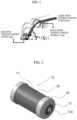
- a filament winding process is applied to manufacture the high-pressure container by winding a fiber composite. Since the entire surface of the liner is continuously wound, a composite material layer in a knuckle region of a dome portion is formed to be relatively thin compared to other portions, as shown in FIG. 1 . Due to the relatively thin composite layer of the knuckle region, there is a high possibility of damage, such as damage to the knuckle region due to external impact.
- the disclosure attempts to provide a high-pressure including an impact-resistant reinforcing member capable of protecting the high-pressure container from external impact, and especially, protecting a knuckle region, which is a relatively vulnerable in the high-pressure container.
- a high-pressure container includes a container body including a cylinder portion and a dome portion formed at both ends of the cylinder portion, wherein the dome portion is formed with a boss portion or a knob portion; a composite layer provided on a surface of the container body; and an impact-resistant reinforcing member covering at least a portion of the composite layer on the dome portion in the composite layer, wherein the impact-resistant reinforcing member has an inner surface in contact with the composite layer on the container body.
- the impact-resistant reinforcing member may include: a through-hole in which the boss portion or the knob portion is disposed; and a cone-shaped first portion extending from an outer periphery of the through-hole along the dome portion and a cylindrical second portion extending from the first portion along the cylinder portion.
- the portion covered by the impact-resistant reinforcing member may include a knuckle point having a smallest thickness in the composite layer, and the first portion and the second portion of the impact-resistant reinforcing member may be divided by a division line I, as a boundary, defined by a straight line perpendicular to a tangent t of a convex portion at which a path changes in an outer surface of the composite layer wound around the knuckle point.
- the first portion and the second portion of the impact-resistant reinforcing member may have a thickness that increases toward the division line I.
- the impact-resistant reinforcing member may be formed of expanded polypropylene (EPP).
- EPP expanded polypropylene
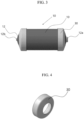
- FIG. 2 is a perspective view schematically illustrating a high-pressure container including an impact-resistant reinforcing member according to the disclosure.
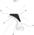
- FIG. 3 is a side view of the high-pressure container of FIG. 2 .
- the high-pressure container includes a container body 10, a composite layer 20, and an impact-resistant reinforcing member 30.
- the container body 10 includes a cylinder portion 11 and a dome portion 12 formed at both ends of the cylinder portion 11.
- the cylinder portion 11 has a cylindrical shape and extends in a longitudinal direction of the container body 10, and the dome portion 12 extends from the cylinder portion 11 and is formed to have a dome shape at both ends of the cylinder portion 11.
- a boss portion 12a is formed in one dome portion 12 based on the cylinder portion 11, and a knob portion 12b is formed in the other dome portion 12.
- the composite layer 20 is provided on a surface of the container body.
- the composite layer 20 is formed by continuously winding a composite material formed of carbon fiber and glass fiber.
- the composite layer 20 is formed by a composite winder moving around the container body and winding the composite material around the container body.
- FIG. 4 is a perspective view illustrating the impact-resistant reinforcing member of FIG. 2 .
- FIG. 5 is a cross-sectional view illustrating a state in which the impact-resistant reinforcing member of the high-pressure container of FIG. 2 is attached.
- the impact-resistant reinforcing member 30 is formed to cover at least a portion of the composite layer 20 on the dome portion 12 of the composite layer 20.
- An inner surface of the impact-resistant reinforcing member 30 is formed in contact with the composite layer 20 on the container body 10. Adhesive is applied to the inner surface of the impact-resistant reinforcing member 30, and the impact-resistant reinforcing member 30 may be pressed toward the container body 10 to be attached to the container body 10.
- the impact-resistant reinforcing member 30 is formed of expanded polypropylene (EPP) in the form of lightweight foam with excellent impact resistance.
- the expanded polypropylene (EPP) has a higher elongation than general plastic, so it is possible to secure a high energy absorption area in a stress-strain curve.
- the impact-resistant reinforcing member 30 includes a through-hole 31, a cone-shaped first portion 32, and a cylindrical second portion 33.
- the boss portion 12a or the knob portion 12b is disposed in the through-hole 31.
- the impact-resistant reinforcing member 30 is inserted into the dome portion 12 of the container body 10, and the boss portion 12a or the knob portion 12b is exposed to the outside through the through-hole 31.
- the cone-shaped first portion 32 extends from an outer periphery of the through-hole 31 along the dome portion 12.
- the cylindrical second portion 33 extends from the first portion 32 along the cylindrical portion 11.
- a portion covered by the impact-resistant reinforcing member 30 includes a knuckle point having the thinnest thickness in the composite layer 20.
- a composite material is wound around the container body 10 to form the composite layer 20, and here, the process follows the following design to improve durability of the high-pressure container.
- the composite material wound around the boss portion 12a is thicker than the cylinder portion 11 due to folding and overlap.
- hoop winding is performed to reinforce only the cylinder portion 11. Accordingly, as shown in FIG. 1 , the composite layer 20 has a relatively small thickness at the knuckle point than at the cylinder portion 11 and the boss portion 12a.
- the composite layer wound around the container body 10 is formed to have a thickness of about 25 mm at the cylinder portion 11, 10 to 15 mm at the knuckle point, and 40 mm at the dome portion 12. This knuckle point is evaluated as a portion which is most vulnerable to impact when the high-pressure container is dropped at 45°.
- the first portion 32 and the second portion 33 of the impact-resistant reinforcing member 30 are separated by a division line I as a boundary, and the division line I is defined by a straight line perpendicular to the tangent t of a convex portion at which a path changes in the outer surface of the composite layer 20 wound around the knuckle point on the dome portion 12 side.
- the thicknesses of the first portion 32 and the second portion 33 of the impact-resistant reinforcing member 30 increase toward the division line I. Accordingly, for example, the knuckle region, in which the largest amount of compression occurs and which is most vulnerable to impact when the high-pressure container is dropped at a 45° angle, may be effectively reinforced.
- FIG. 6 is a diagram illustrating each of states before and after a collision during a drop test of the high-pressure container including an impact-resistant reinforcing member of FIG. 2 .
- Table 1 shows experimental results of Examples 1 and 2 of the expanded polypropylene (EPP) of the disclosure and Comparative Examples 1 and 2.
- HF-1 as a flame-retardant effect in Table 1 below refers to a flame retardant test on materials, such as foam or sponge, among a plurality of flame retardant grades of UL94, a physical and chemical test standard established by "Underwriters Laboratories," an American safety certification company.
- Example 1 Comparativ e Example 1 Comparative Example 2 (elastomer-based polyurethane foam Material composition (wt%) Ethylene-propylene copolymer resin 62 % 70% 92% Modified olefin-based resin 30 % 30% 0% Flame retardant 8% 0% 8% Sum 100% 100% 100% Effect Drop impact protection Good (No damage to composite/impa ct resistant foam) Good (No damage to composite/impa ct resistant foam) Average (surface of composite is damaged, cracks are discovered in impact resistant foam) Good (No damage to composite/impa ct resistant foam) Lightweigh t effect (lightweigh t ratio) 240 g/EA (77 %) 250 g/EA (76 %) 320 g/EA (69 %) 1.041 g/EA (100 %) Flame-retardant effect HF-1 is satisfied Flame retardant performance is HF-1 is satisfied Flame retardant performance is not satisfied not satisfied (Toxic substance is detected) Room temperatur
- Example 1 shows a case in which expanded polypropylene (EPP) includes an ethylene-propylene copolymer resin, a modified olefin resin, and a flame retardant
- Example 2 shows a case in which expanded polypropylene (EPP) includes an ethylene-propylene copolymer resin and a modified olefin resin, excluding a flame retardant.
- EPP expanded polypropylene
- Comparative Example 1 shows a case in which expanded polypropylene (EPP) includes an ethylene-propylene copolymer resin and a flame retardant, excluding modified olefin resin
- Comparative Example 2 shows a case in which an elastomer-based polyurethane foam, other than expanded polypropylene (EPP), is applied.
- EPP expanded polypropylene
- EPP 2 shows a case in which an elastomer-based polyurethane foam, other than expanded polypropylene (EPP), is applied.
- the expanded polypropylene (EPP) applied to the impact-resistant reinforcing member 30 according to the disclosure may include an ethylene-propylene copolymer in the range of 60 to 80 % based on a total weight.
- Example 1 an ethylene-propylene copolymer resin is included in the range of 60 to 80 % based on the total weight of expanded polypropylene (EPP), and a modified olefin resin and a flame retardant are further included.
- the expanded polypropylene (EPP) according to Example 1 may include 62 % ethylene-propylene copolymer resin, 30 % modified olefin resin, and 8 % flame retardant.
- Example 2 an ethylene-propylene copolymer resin is included in the range of 60 to 80 % based on the total weight of expanded polypropylene (EPP), and a modified olefin resin is further included. In Example 2, no flame retardant is included.
- the expanded polypropylene (EPP) according to Example 2 may include 70% ethylene-propylene copolymer resin and 30% modified olefin resin.
- compositions of the ethylene-polypropylene copolymer resin, modified olefin resin, and flame retardant are listed as specific values rather than ranges, but this is only an example and may be selected within a weight ratio range of the respective materials described above.
- Comparative Example 1 92% ethylene-propylene copolymer resin and 8% flame retardant may be included based on the total weight of expanded polypropylene (EPP).
- EPP expanded polypropylene
- Example 1 no damage occurred in the composite layer and the impact-resistant reinforcing member, and a high weight reduction rate of 77% and a flame-retardant effect satisfying HF-1 were exhibited. Meanwhile, as a result of repeated room temperature pressure tests, no leaks occurred even after 22,000 tests.
- Example 2 no damage occurred in the composite layer and the impact-resistant reinforcing member, and a high weight reduction rate of 76% was exhibited, but a flame-retardant effect was not demonstrated because no flame retardant was included. Meanwhile, as a result of repeated room temperature pressure tests, no leaks occurred even after 22,000 tests.
- Comparative Example 1 surface damage occurred in the composite layer, and cracks were found in the impact-resistant reinforcing member. In addition, a weight reduction rate of 69% was shown, which was lower than those of Examples 1 and 2. Meanwhile, as a result of repeated room temperature pressure tests, water leakage occurred in tests under 22,000 times.
Landscapes
- Engineering & Computer Science (AREA)
- Mechanical Engineering (AREA)
- General Engineering & Computer Science (AREA)
- Laminated Bodies (AREA)
- Compositions Of Macromolecular Compounds (AREA)
Abstract
Description
- The disclosure relates to a high-pressure container including an impact-resistant reinforcing member, and more particularly, to a high-pressure container with a composite material wound therearound having improved impact-resistant performance by using an impact-resistant reinforcing member.
- Among high-pressure containers that store high-pressure gases, including hydrogen, Type 4 high-pressure container is manufactured by forming a liner using polyolefin (HDPE, PA) materials and then winding a composite material formed of carbon fiber and glass fiber around the liner. Here, metal (Al) is applied to some parts to increase durability, prevent gas leakage, and fixing during winding.
- When manufacturing the Type 4 high-pressure container, a filament winding process is applied to manufacture the high-pressure container by winding a fiber composite. Since the entire surface of the liner is continuously wound, a composite material layer in a knuckle region of a dome portion is formed to be relatively thin compared to other portions, as shown in
FIG. 1 . Due to the relatively thin composite layer of the knuckle region, there is a high possibility of damage, such as damage to the knuckle region due to external impact. - Therefore, there is a need for a device that may protect the relatively vulnerable knuckle region in a high-pressure container.
- The disclosure attempts to provide a high-pressure including an impact-resistant reinforcing member capable of protecting the high-pressure container from external impact, and especially, protecting a knuckle region, which is a relatively vulnerable in the high-pressure container.
- According to an exemplary embodiment, a high-pressure container includes a container body including a cylinder portion and a dome portion formed at both ends of the cylinder portion, wherein the dome portion is formed with a boss portion or a knob portion; a composite layer provided on a surface of the container body; and an impact-resistant reinforcing member covering at least a portion of the composite layer on the dome portion in the composite layer, wherein the impact-resistant reinforcing member has an inner surface in contact with the composite layer on the container body.
- The impact-resistant reinforcing member may include: a through-hole in which the boss portion or the knob portion is disposed; and a cone-shaped first portion extending from an outer periphery of the through-hole along the dome portion and a cylindrical second portion extending from the first portion along the cylinder portion.
- The portion covered by the impact-resistant reinforcing member may include a knuckle point having a smallest thickness in the composite layer, and the first portion and the second portion of the impact-resistant reinforcing member may be divided by a division line I, as a boundary, defined by a straight line perpendicular to a tangent t of a convex portion at which a path changes in an outer surface of the composite layer wound around the knuckle point.
- The first portion and the second portion of the impact-resistant reinforcing member may have a thickness that increases toward the division line I.
- The impact-resistant reinforcing member may be formed of expanded polypropylene (EPP).
- According to an exemplary embodiment of the disclosure, it is possible to effectively protect the high-pressure container from external impact, and especially, the relatively vulnerable knuckle region of the high-pressure container.
-
-
FIG. 1 is a schematic diagram illustrating a cross-section of a dome portion of a high-pressure container around which a composite material is wound in the related art. -
FIG. 2 is a perspective view schematically illustrating a high-pressure container including an impact-resistant reinforcing member according to the disclosure. -
FIG. 3 is a side view of the high-pressure container ofFIG. 2 . -
FIG. 4 is a perspective view illustrating an impact-resistant reinforcing member ofFIG. 2 . -
FIG. 5 is a cross-sectional view illustrating a state in which the impact-resistant reinforcing member of the high-pressure container ofFIG. 2 is attached. -
FIG. 6 is a diagram illustrating each of states before and after a collision during a drop test of the high-pressure container including an impact-resistant reinforcing member ofFIG. 2 . - Hereinafter, the disclosure is described with reference to the accompanying drawings. However, the disclosure may be modified in various different ways, and is not limited to the exemplary embodiments set forth herein. Portions that are irrelevant to the description will be omitted to clearly describe the disclosure, and same reference numerals designate same or like elements throughout the description.
- Throughout the specification, when a portion is referred to as being "connected (contact, coupled)" to another part, it may not only be "directly connected" to the other portion but also may be "indirectly connected" to the other portion via an intervening member. Therefore, unless explicitly described to the contrary, the word "comprise" will be understood to imply the inclusion of stated elements but not the exclusion of any other elements.
- Terms used in the present application are used only to describe specific exemplary embodiments, and are not intended to limit the disclosure. A singular form may include a plural form if there is no clearly opposite meaning in the context. Throughout the specification, the terms, such as "include" and "have" are intended to indicate that features, numbers, steps, operations, elements, components, or combinations thereof used in the following description exist and it should be thus understood that the possibility of existence or addition of one or more different features, numbers, steps, operations, elements, components, or combinations thereof is not excluded.
- Exemplary embodiments of the disclosure are described in detail with reference to the accompanying drawings.
-
FIG. 2 is a perspective view schematically illustrating a high-pressure container including an impact-resistant reinforcing member according to the disclosure.FIG. 3 is a side view of the high-pressure container ofFIG. 2 . - Referring to
FIGS. 2 and3 , the high-pressure container according to the disclosure includes acontainer body 10, acomposite layer 20, and an impact-resistant reinforcingmember 30. - The
container body 10 includes acylinder portion 11 and adome portion 12 formed at both ends of thecylinder portion 11. Thecylinder portion 11 has a cylindrical shape and extends in a longitudinal direction of thecontainer body 10, and thedome portion 12 extends from thecylinder portion 11 and is formed to have a dome shape at both ends of thecylinder portion 11. Aboss portion 12a is formed in onedome portion 12 based on thecylinder portion 11, and aknob portion 12b is formed in theother dome portion 12. - The
composite layer 20 is provided on a surface of the container body. Thecomposite layer 20 is formed by continuously winding a composite material formed of carbon fiber and glass fiber. Thecomposite layer 20 is formed by a composite winder moving around the container body and winding the composite material around the container body. -
FIG. 4 is a perspective view illustrating the impact-resistant reinforcing member ofFIG. 2 .FIG. 5 is a cross-sectional view illustrating a state in which the impact-resistant reinforcing member of the high-pressure container ofFIG. 2 is attached. - Referring to
FIGS. 4 and5 , the impact-resistant reinforcingmember 30 is formed to cover at least a portion of thecomposite layer 20 on thedome portion 12 of thecomposite layer 20. An inner surface of the impact-resistant reinforcingmember 30 is formed in contact with thecomposite layer 20 on thecontainer body 10. Adhesive is applied to the inner surface of the impact-resistant reinforcingmember 30, and the impact-resistant reinforcingmember 30 may be pressed toward thecontainer body 10 to be attached to thecontainer body 10. The impact-resistant reinforcingmember 30 is formed of expanded polypropylene (EPP) in the form of lightweight foam with excellent impact resistance. The expanded polypropylene (EPP) has a higher elongation than general plastic, so it is possible to secure a high energy absorption area in a stress-strain curve. - The impact-resistant reinforcing
member 30 includes a through-hole 31, a cone-shapedfirst portion 32, and a cylindricalsecond portion 33. Theboss portion 12a or theknob portion 12b is disposed in the through-hole 31. When installed, the impact-resistant reinforcingmember 30 is inserted into thedome portion 12 of thecontainer body 10, and theboss portion 12a or theknob portion 12b is exposed to the outside through the through-hole 31. The cone-shapedfirst portion 32 extends from an outer periphery of the through-hole 31 along thedome portion 12. The cylindricalsecond portion 33 extends from thefirst portion 32 along thecylindrical portion 11. - A portion covered by the impact-resistant reinforcing
member 30 includes a knuckle point having the thinnest thickness in thecomposite layer 20. In a filament winding process applied to the high-pressure container, a composite material is wound around thecontainer body 10 to form thecomposite layer 20, and here, the process follows the following design to improve durability of the high-pressure container. The composite material wound around theboss portion 12a is thicker than thecylinder portion 11 due to folding and overlap. In addition, in order to reduce a high load occurring in thecylinder portion 11 having the largest diameter, hoop winding is performed to reinforce only thecylinder portion 11. Accordingly, as shown inFIG. 1 , thecomposite layer 20 has a relatively small thickness at the knuckle point than at thecylinder portion 11 and theboss portion 12a. Generally, the composite layer wound around thecontainer body 10 is formed to have a thickness of about 25 mm at thecylinder portion dome portion 12. This knuckle point is evaluated as a portion which is most vulnerable to impact when the high-pressure container is dropped at 45°. - The
first portion 32 and thesecond portion 33 of the impact-resistant reinforcingmember 30 are separated by a division line I as a boundary, and the division line I is defined by a straight line perpendicular to the tangent t of a convex portion at which a path changes in the outer surface of thecomposite layer 20 wound around the knuckle point on thedome portion 12 side. The thicknesses of thefirst portion 32 and thesecond portion 33 of the impact-resistant reinforcingmember 30 increase toward the division line I. Accordingly, for example, the knuckle region, in which the largest amount of compression occurs and which is most vulnerable to impact when the high-pressure container is dropped at a 45° angle, may be effectively reinforced. -
FIG. 6 is a diagram illustrating each of states before and after a collision during a drop test of the high-pressure container including an impact-resistant reinforcing member ofFIG. 2 . In addition, Table 1 below shows experimental results of Examples 1 and 2 of the expanded polypropylene (EPP) of the disclosure and Comparative Examples 1 and 2. HF-1 as a flame-retardant effect in Table 1 below refers to a flame retardant test on materials, such as foam or sponge, among a plurality of flame retardant grades of UL94, a physical and chemical test standard established by "Underwriters Laboratories," an American safety certification company.<Table 1> Example 1 Example 2 Comparativ e Example 1 Comparative Example 2 (elastomer-based polyurethane foam Material composition (wt%) Ethylene-propylene copolymer resin 62 % 70% 92% Modified olefin-based resin 30 % 30% 0% Flame retardant 8% 0% 8% Sum 100% 100% 100% Effect Drop impact protection Good (No damage to composite/impa ct resistant foam) Good (No damage to composite/impa ct resistant foam) Average (surface of composite is damaged, cracks are discovered in impact resistant foam) Good (No damage to composite/impa ct resistant foam) Lightweigh t effect (lightweigh t ratio) 240 g/EA (77 %) 250 g/EA (76 %) 320 g/EA (69 %) 1.041 g/EA (100 %) Flame-retardant effect HF-1 is satisfied Flame retardant performance is HF-1 is satisfied Flame retardant performance is not satisfied not satisfied (Toxic substance is detected) Room temperatur e pressure repetition test results 22,000 times No leak 22,000 times No leak 22,000 times or less Water leak 22,000 times No leak - Referring to
FIG. 6 and Table 1, Example 1 shows a case in which expanded polypropylene (EPP) includes an ethylene-propylene copolymer resin, a modified olefin resin, and a flame retardant, and Example 2 shows a case in which expanded polypropylene (EPP) includes an ethylene-propylene copolymer resin and a modified olefin resin, excluding a flame retardant. Comparative Example 1 shows a case in which expanded polypropylene (EPP) includes an ethylene-propylene copolymer resin and a flame retardant, excluding modified olefin resin, and Comparative Example 2 shows a case in which an elastomer-based polyurethane foam, other than expanded polypropylene (EPP), is applied. - In this experiment, after attaching the impact-resistant reinforcing members to which the above materials were applied to the knuckle portion of the high-pressure container, a free fall experiment was conducted on the high-pressure container in four directions: 0°, ±90°, and 45° from a height of 1.8 m above the ground. Here, in order to measure a lightweight effect of the impact-resistant reinforcing members, impact-resistant reinforcing members were manufactured to have the same size and compared.
- Referring to Examples 1 and 2 of Table 1, the expanded polypropylene (EPP) applied to the impact-resistant reinforcing
member 30 according to the disclosure may include an ethylene-propylene copolymer in the range of 60 to 80 % based on a total weight. - In Example 1, an ethylene-propylene copolymer resin is included in the range of 60 to 80 % based on the total weight of expanded polypropylene (EPP), and a modified olefin resin and a flame retardant are further included. A ratio (B/A) of a weight (A) of the ethylene-propylene copolymer resin and a weight (B) of the modified olefin resin may be selected within the range of 0.375 (B1/A1=0.3/0.8) to 0.5 (B2/A2=0.3/0.6). A ratio (C/A) of the weight (A) of the ethylene-propylene copolymer resin and a weight (C) of the flame retardant may be selected within the range of 0.1 (C1/A1=0.08/0.8) to 0.133 (C2/A2=0.08/0.6). For example, the expanded polypropylene (EPP) according to Example 1 may include 62 % ethylene-propylene copolymer resin, 30 % modified olefin resin, and 8 % flame retardant.
- In Example 2, an ethylene-propylene copolymer resin is included in the range of 60 to 80 % based on the total weight of expanded polypropylene (EPP), and a modified olefin resin is further included. In Example 2, no flame retardant is included. A ratio (B'/A') of a weight (A') of the ethylene-propylene copolymer resin and a weight (B') of the modified olefin resin may be selected within the range of 0.375 (B1'/A1'=0.3/0.8) to 0.5 (B2'/A2'=0.3/0.6). For example, the expanded polypropylene (EPP) according to Example 2 may include 70% ethylene-propylene copolymer resin and 30% modified olefin resin. In Table 1, the compositions of the ethylene-polypropylene copolymer resin, modified olefin resin, and flame retardant are listed as specific values rather than ranges, but this is only an example and may be selected within a weight ratio range of the respective materials described above.
- In Comparative Example 1, 92% ethylene-propylene copolymer resin and 8% flame retardant may be included based on the total weight of expanded polypropylene (EPP).
- In Comparative Example 2, elastomer-based polyurethane foam, rather than expanded polypropylene (EPP), was applied.
- The experimental results are as follows.
- In Example 1, no damage occurred in the composite layer and the impact-resistant reinforcing member, and a high weight reduction rate of 77% and a flame-retardant effect satisfying HF-1 were exhibited. Meanwhile, as a result of repeated room temperature pressure tests, no leaks occurred even after 22,000 tests.
- In Example 2, no damage occurred in the composite layer and the impact-resistant reinforcing member, and a high weight reduction rate of 76% was exhibited, but a flame-retardant effect was not demonstrated because no flame retardant was included. Meanwhile, as a result of repeated room temperature pressure tests, no leaks occurred even after 22,000 tests.
- In Comparative Example 1, surface damage occurred in the composite layer, and cracks were found in the impact-resistant reinforcing member. In addition, a weight reduction rate of 69% was shown, which was lower than those of Examples 1 and 2. Meanwhile, as a result of repeated room temperature pressure tests, water leakage occurred in tests under 22,000 times.
- In Comparative Example 2, no damage occurred in the composite layer and the impact-resistant reinforcing member, but the flame retardant performance HF-1 was not satisfied, and toxic substances occurred during fire.
- The scope of the disclosure is defined by the appended claims, rather than the detailed description, and should be construed as including all modifications and variations derived from the meaning and scope of the claims and concept equivalent thereto.
-
10: container body 11: cylinder portion 12: dome portion 12a: boss portion 12b: knob portion 20: composite material layer 30: impact-resistant reinforcing member 31: through-hole 32: cone-shaped first portion 33: cylindrical second portion I: division line
Claims (5)
- A high-pressure container including an impact-resistant reinforcing member, the high-pressure container comprising:a container body including a cylinder portion and a dome portion formed at both ends of the cylinder portion, wherein the dome portion is formed with a boss portion or a knob portion;a composite layer provided on a surface of the container body; andan impact-resistant reinforcing member covering at least a portion of the composite layer on the dome portion in the composite layer,wherein the impact-resistant reinforcing member has an inner surface in contact with the composite layer on the container body.
- The high-pressure container of claim 1, wherein:
the impact-resistant reinforcing member includes:a through-hole in which the boss portion or the knob portion is disposed; anda cone-shaped first portion extending from an outer periphery of the through-hole along the dome portion and a cylindrical second portion extending from the first portion along the cylinder portion. - The high-pressure container of claim 2, wherein:the portion covered by the impact-resistant reinforcing member includes a knuckle point having a smallest thickness in the composite layer, andthe first portion and the second portion of the impact-resistant reinforcing member are divided by a division line I, as a boundary, defined by a straight line perpendicular to a tangent t of a convex portion at which a path changes in an outer surface of the composite layer wound around the knuckle point.
- The high-pressure container of claim 3, wherein:
the first portion and the second portion of the impact-resistant reinforcing member have a thickness that increases toward the division line I. - The high-pressure container of any one of claim 1 to claim 4, wherein:
the impact-resistant reinforcing member is formed of expanded polypropylene (EPP).
Applications Claiming Priority (2)
| Application Number | Priority Date | Filing Date | Title |
|---|---|---|---|
| KR1020210164912A KR20230077541A (en) | 2021-11-25 | 2021-11-25 | High pressure vessel with impact-resistant foam |
| PCT/KR2022/017866 WO2023096238A1 (en) | 2021-11-25 | 2022-11-14 | High-pressure vessel having impact-resistant stiffener member |
Publications (2)
| Publication Number | Publication Date |
|---|---|
| EP4438937A1 true EP4438937A1 (en) | 2024-10-02 |
| EP4438937A4 EP4438937A4 (en) | 2025-11-19 |
Family
ID=86539878
Family Applications (1)
| Application Number | Title | Priority Date | Filing Date |
|---|---|---|---|
| EP22898920.8A Pending EP4438937A4 (en) | 2021-11-25 | 2022-11-14 | HIGH-PRESSURE CONTAINER WITH IMPACT-RESISTANT REINFORCEMENT ELEMENT |
Country Status (4)
| Country | Link |
|---|---|
| US (1) | US20250012402A1 (en) |
| EP (1) | EP4438937A4 (en) |
| KR (1) | KR20230077541A (en) |
| WO (1) | WO2023096238A1 (en) |
Cited By (1)
| Publication number | Priority date | Publication date | Assignee | Title |
|---|---|---|---|---|
| US12529449B2 (en) | 2023-07-11 | 2026-01-20 | Toyota Jidosha Kabushiki Kaisha | Pressure tank unit |
Family Cites Families (13)
| Publication number | Priority date | Publication date | Assignee | Title |
|---|---|---|---|---|
| US7350665B2 (en) * | 1999-04-19 | 2008-04-01 | Claude Leon Hembert | Device to protect the domes and ends of a composite tank |
| JP2004263827A (en) * | 2003-03-04 | 2004-09-24 | Mitsubishi Rayon Co Ltd | Pressure vessel and method of manufacturing the same |
| US7699188B2 (en) * | 2004-04-23 | 2010-04-20 | Amtrol Licensing Inc. | Hybrid pressure vessel with separable jacket |
| JP2009108971A (en) * | 2007-10-31 | 2009-05-21 | Nissan Motor Co Ltd | Pressure vessel protection structure |
| PL2933547T3 (en) * | 2014-04-17 | 2020-01-31 | Schmitt Prof. Möhlmann & Collegen Wirtschaftskanzlei -Insolvenzverwalter Aktiengesellschaft | Valve protection basket for the protection of gas cylinder valves |
| JP6515793B2 (en) * | 2015-12-03 | 2019-05-22 | トヨタ自動車株式会社 | High pressure gas tank |
| MX2018011478A (en) * | 2016-03-23 | 2019-01-10 | Worthington Ind Inc | Boss and liner interface for a pressure vessel. |
| JP7311243B2 (en) * | 2017-12-28 | 2023-07-19 | トヨタ自動車株式会社 | High pressure tank with protector |
| JP6695365B2 (en) * | 2018-01-25 | 2020-05-20 | 本田技研工業株式会社 | High pressure tank structure |
| EP3870889B1 (en) * | 2018-10-24 | 2024-05-22 | AMTROL Licensing Inc. | Hybrid pressure vessel with plastic liner |
| JP7263776B2 (en) * | 2019-01-07 | 2023-04-25 | トヨタ自動車株式会社 | high pressure tank |
| KR102401745B1 (en) | 2019-11-27 | 2022-05-25 | 롯데케미칼 주식회사 | High pressure tank with hoop layer and helical layer and manufacturing method thereof |
| WO2022256022A1 (en) * | 2021-06-01 | 2022-12-08 | Helicoid Industries Inc. | Containers and methods for protecting pressure vessels |
-
2021
- 2021-11-25 KR KR1020210164912A patent/KR20230077541A/en active Pending
-
2022
- 2022-11-14 US US18/712,394 patent/US20250012402A1/en active Pending
- 2022-11-14 EP EP22898920.8A patent/EP4438937A4/en active Pending
- 2022-11-14 WO PCT/KR2022/017866 patent/WO2023096238A1/en not_active Ceased
Cited By (1)
| Publication number | Priority date | Publication date | Assignee | Title |
|---|---|---|---|---|
| US12529449B2 (en) | 2023-07-11 | 2026-01-20 | Toyota Jidosha Kabushiki Kaisha | Pressure tank unit |
Also Published As
| Publication number | Publication date |
|---|---|
| KR20230077541A (en) | 2023-06-01 |
| US20250012402A1 (en) | 2025-01-09 |
| WO2023096238A1 (en) | 2023-06-01 |
| EP4438937A4 (en) | 2025-11-19 |
Similar Documents
| Publication | Publication Date | Title |
|---|---|---|
| KR102251861B1 (en) | High pressure tank | |
| Wanchoo et al. | Investigations on air and underwater blast mitigation in polymeric composite structures–A review | |
| KR102043080B1 (en) | High pressure vessel and manufacturing method of the same | |
| EP3587882B1 (en) | Hydrogen transport component | |
| JPH0835598A (en) | Pressure vessel having damage reduction system | |
| KR102250241B1 (en) | Refractory agent | |
| KR101565732B1 (en) | A fabric with gas sheet | |
| KR20040019305A (en) | Laminated ballistic structure comprising alternating unidirectional and thermoplastic layers | |
| CN113211819A (en) | Composite explosion-proof barrel and fiber composite curved surface member forming method | |
| US20210359361A1 (en) | Solid-state battery packaging material and solid-state battery using the same | |
| KR20120038618A (en) | Multilayered super barrier sealing member for vacuum insulation materials having excellent gas barrier property | |
| CA2161137A1 (en) | Composite element | |
| KR20230077541A (en) | High pressure vessel with impact-resistant foam | |
| KR20230000022A (en) | Sealant film for cell pouch having barrier properties using hygroscopicity of inorganic materals, cell pouch including the same and method for preparing the same | |
| JP2024063250A (en) | Packaging film for power storage device and power storage device | |
| EP0340877A1 (en) | Ballistic structure | |
| JP7263776B2 (en) | high pressure tank | |
| KR102453069B1 (en) | delaminate container | |
| KR101502404B1 (en) | An outer cover fabric of protective clothing and method for manufacturing the outer cover fabric | |
| CN222033430U (en) | Anti-flaming chemical-proof clothing window | |
| KR102431137B1 (en) | Carriers lighter than air having a hull and laminates for such hulls and methods for manufacturing such laminates | |
| CN214525779U (en) | High-strength impact-resistant packaging tube | |
| KR102791318B1 (en) | Laminated structure for secondary battery pouch | |
| KR101751474B1 (en) | Rubber coating composition for chemical proof cloths, textiles thereby and mathod therfor | |
| CN220363071U (en) | Composite functional fabric and protective product |
Legal Events
| Date | Code | Title | Description |
|---|---|---|---|
| STAA | Information on the status of an ep patent application or granted ep patent |
Free format text: STATUS: THE INTERNATIONAL PUBLICATION HAS BEEN MADE |
|
| PUAI | Public reference made under article 153(3) epc to a published international application that has entered the european phase |
Free format text: ORIGINAL CODE: 0009012 |
|
| STAA | Information on the status of an ep patent application or granted ep patent |
Free format text: STATUS: REQUEST FOR EXAMINATION WAS MADE |
|
| 17P | Request for examination filed |
Effective date: 20240606 |
|
| AK | Designated contracting states |
Kind code of ref document: A1 Designated state(s): AL AT BE BG CH CY CZ DE DK EE ES FI FR GB GR HR HU IE IS IT LI LT LU LV MC ME MK MT NL NO PL PT RO RS SE SI SK SM TR |
|
| DAV | Request for validation of the european patent (deleted) | ||
| DAX | Request for extension of the european patent (deleted) | ||
| A4 | Supplementary search report drawn up and despatched |
Effective date: 20251021 |
|
| RIC1 | Information provided on ipc code assigned before grant |
Ipc: F17C 1/02 20060101AFI20251015BHEP Ipc: F17C 13/00 20060101ALI20251015BHEP |