EP4438916A1 - Improved friction clutch system - Google Patents
Improved friction clutch system Download PDFInfo
- Publication number
- EP4438916A1 EP4438916A1 EP23164348.7A EP23164348A EP4438916A1 EP 4438916 A1 EP4438916 A1 EP 4438916A1 EP 23164348 A EP23164348 A EP 23164348A EP 4438916 A1 EP4438916 A1 EP 4438916A1
- Authority
- EP
- European Patent Office
- Prior art keywords
- clutch arrangement
- clutch
- rotating means
- unit
- friction
- Prior art date
- Legal status (The legal status is an assumption and is not a legal conclusion. Google has not performed a legal analysis and makes no representation as to the accuracy of the status listed.)
- Granted
Links
Images




Classifications
-
- F—MECHANICAL ENGINEERING; LIGHTING; HEATING; WEAPONS; BLASTING
- F16—ENGINEERING ELEMENTS AND UNITS; GENERAL MEASURES FOR PRODUCING AND MAINTAINING EFFECTIVE FUNCTIONING OF MACHINES OR INSTALLATIONS; THERMAL INSULATION IN GENERAL
- F16D—COUPLINGS FOR TRANSMITTING ROTATION; CLUTCHES; BRAKES
- F16D13/00—Friction clutches
- F16D13/22—Friction clutches with axially-movable clutching members
- F16D13/38—Friction clutches with axially-movable clutching members with flat clutching surfaces, e.g. discs
- F16D13/52—Clutches with multiple lamellae ; Clutches in which three or more axially moveable members are fixed alternately to the shafts to be coupled and are pressed from one side towards an axially-located member
- F16D13/54—Clutches with multiple lamellae ; Clutches in which three or more axially moveable members are fixed alternately to the shafts to be coupled and are pressed from one side towards an axially-located member with means for increasing the effective force between the actuating sleeve or equivalent member and the pressure member
- F16D13/56—Clutches with multiple lamellae ; Clutches in which three or more axially moveable members are fixed alternately to the shafts to be coupled and are pressed from one side towards an axially-located member with means for increasing the effective force between the actuating sleeve or equivalent member and the pressure member in which the clutching pressure is produced by springs only
-
- F—MECHANICAL ENGINEERING; LIGHTING; HEATING; WEAPONS; BLASTING
- F16—ENGINEERING ELEMENTS AND UNITS; GENERAL MEASURES FOR PRODUCING AND MAINTAINING EFFECTIVE FUNCTIONING OF MACHINES OR INSTALLATIONS; THERMAL INSULATION IN GENERAL
- F16D—COUPLINGS FOR TRANSMITTING ROTATION; CLUTCHES; BRAKES
- F16D25/00—Fluid-actuated clutches
- F16D25/06—Fluid-actuated clutches in which the fluid actuates a piston incorporated in, i.e. rotating with the clutch
- F16D25/062—Fluid-actuated clutches in which the fluid actuates a piston incorporated in, i.e. rotating with the clutch the clutch having friction surfaces
- F16D25/063—Fluid-actuated clutches in which the fluid actuates a piston incorporated in, i.e. rotating with the clutch the clutch having friction surfaces with clutch members exclusively moving axially
- F16D25/0635—Fluid-actuated clutches in which the fluid actuates a piston incorporated in, i.e. rotating with the clutch the clutch having friction surfaces with clutch members exclusively moving axially with flat friction surfaces, e.g. discs
- F16D25/0638—Fluid-actuated clutches in which the fluid actuates a piston incorporated in, i.e. rotating with the clutch the clutch having friction surfaces with clutch members exclusively moving axially with flat friction surfaces, e.g. discs with more than two discs, e.g. multiple lamellae
-
- F—MECHANICAL ENGINEERING; LIGHTING; HEATING; WEAPONS; BLASTING
- F16—ENGINEERING ELEMENTS AND UNITS; GENERAL MEASURES FOR PRODUCING AND MAINTAINING EFFECTIVE FUNCTIONING OF MACHINES OR INSTALLATIONS; THERMAL INSULATION IN GENERAL
- F16D—COUPLINGS FOR TRANSMITTING ROTATION; CLUTCHES; BRAKES
- F16D13/00—Friction clutches
- F16D13/58—Details
- F16D13/583—Diaphragm-springs, e.g. Belleville
-
- F—MECHANICAL ENGINEERING; LIGHTING; HEATING; WEAPONS; BLASTING
- F16—ENGINEERING ELEMENTS AND UNITS; GENERAL MEASURES FOR PRODUCING AND MAINTAINING EFFECTIVE FUNCTIONING OF MACHINES OR INSTALLATIONS; THERMAL INSULATION IN GENERAL
- F16D—COUPLINGS FOR TRANSMITTING ROTATION; CLUTCHES; BRAKES
- F16D13/00—Friction clutches
- F16D13/58—Details
- F16D13/70—Pressure members, e.g. pressure plates, for clutch-plates or lamellae; Guiding arrangements for pressure members
-
- F—MECHANICAL ENGINEERING; LIGHTING; HEATING; WEAPONS; BLASTING
- F16—ENGINEERING ELEMENTS AND UNITS; GENERAL MEASURES FOR PRODUCING AND MAINTAINING EFFECTIVE FUNCTIONING OF MACHINES OR INSTALLATIONS; THERMAL INSULATION IN GENERAL
- F16D—COUPLINGS FOR TRANSMITTING ROTATION; CLUTCHES; BRAKES
- F16D25/00—Fluid-actuated clutches
- F16D25/12—Details not specific to one of the before-mentioned types
-
- F—MECHANICAL ENGINEERING; LIGHTING; HEATING; WEAPONS; BLASTING
- F16—ENGINEERING ELEMENTS AND UNITS; GENERAL MEASURES FOR PRODUCING AND MAINTAINING EFFECTIVE FUNCTIONING OF MACHINES OR INSTALLATIONS; THERMAL INSULATION IN GENERAL
- F16D—COUPLINGS FOR TRANSMITTING ROTATION; CLUTCHES; BRAKES
- F16D13/00—Friction clutches
- F16D13/22—Friction clutches with axially-movable clutching members
- F16D13/38—Friction clutches with axially-movable clutching members with flat clutching surfaces, e.g. discs
- F16D13/52—Clutches with multiple lamellae ; Clutches in which three or more axially moveable members are fixed alternately to the shafts to be coupled and are pressed from one side towards an axially-located member
- F16D13/54—Clutches with multiple lamellae ; Clutches in which three or more axially moveable members are fixed alternately to the shafts to be coupled and are pressed from one side towards an axially-located member with means for increasing the effective force between the actuating sleeve or equivalent member and the pressure member
- F16D13/56—Clutches with multiple lamellae ; Clutches in which three or more axially moveable members are fixed alternately to the shafts to be coupled and are pressed from one side towards an axially-located member with means for increasing the effective force between the actuating sleeve or equivalent member and the pressure member in which the clutching pressure is produced by springs only
- F16D2013/565—Clutches with multiple lamellae ; Clutches in which three or more axially moveable members are fixed alternately to the shafts to be coupled and are pressed from one side towards an axially-located member with means for increasing the effective force between the actuating sleeve or equivalent member and the pressure member in which the clutching pressure is produced by springs only with means for releasing the clutch pressure in case of back torque
Definitions
- the present disclosure relates to a clutch arrangement for a vehicle, a vehicle for route planning, a vehicle with a clutch arrangement and/or a use of a shim means in a clutch arrangement.
- Known clutch arrangements comprise either wet clutches, which due to their frictional properties help to avoid NVH vibration effects during shifting, whereby typically high losses occur due to drag torques caused by viscous coupling through the oil between the moving elements.
- dry clutch arrangements are possible using, for example, organic friction material whereby NVH effects such as vibration harshness effects and/or noise harshness effects occur due to the friction material.
- the material is used in a multi-plate design whereby another source of loss is actuation, with most of these multi-plate clutch packs requiring a constant applied force to transmit torque. This consumes energy, but also results in bearing losses due to axial force.
- a clutch arrangement for a vehicle comprising: a first rotating means with at least one friction unit and a second rotating means with at least one pressure unit; whereby the at least one friction unit is configured to be moved between an opened position and a closed position, whereby in the closed position, a force is transmitted between the first rotating means and the second rotating means and whereby in the opened position, no force is transmitted between the first rotating means and the second rotating means; at least one shim means arranged at the first rotating means, whereby the shim means are configured to prevent a contact between the friction unit and the pressure unit, if the friction unit is located in the opened position.
- the at least one friction unit may be an element configured to absorb and/or transmit friction, for example, the element may be configured as a friction disk.
- the at least one pressure unit may be an element configured to absorb and/or transmit pressure, for example, the element may be configured as a pressure plate.
- the at least one shim means may be an element configured to position the at least one friction unit such that no contact occurs between the friction unit and the pressure unit in the open position.
- the at least one shim means may be configured to prevent impacts between the at least one friction unit and the at least one pressure unit when the clutch arrangement is in the opened position.
- the at least one shim means may be configured to prevent the at least one friction unit and the at least one pressure unit from freely impacting each other if the clutch arrangement is open.
- the drag loss due to the usage of wet clutch arrangements may be avoided, as well as NVH effects of known dry clutch arrangement, such as in particular vibration harshness effects and/or noise harshness effects.
- the NVH effects may be reduced by arranging the at least one friction unit and/or the at least one pressure unit separately from each other and defining the relative position between the at least one friction unit and the at least one pressure unit with the at least one shim means.
- the clutch arrangement may comprise two or more friction units and two or more pressure units, preferably five friction units and five pressure units.
- the clutch arrangement may for example be configured as a multidisc clutch or multi-plate clutch.
- the at least one shim means may for example arrange a first friction unit opposite a first pressure unit opposite a second friction unit and so on.
- the arrangement with the shim means may, for example, prevent the five friction units and five pressure units from colliding with each other, thus achieving improved NVH compared to regular clutch arrangements or multi clutch arrangements.
- the clutch arrangement may further comprise at least one first separator means located between two pressure units and configured to position the two pressure units apart from each other.
- the at least one first separator means may be an element configured to position the two pressure units apart from each other, for example, the element is configured as a separator spring.
- the separator spring may arrange the pressure units with a controlled gap between each other to may be reduce the drag in the clutch arrangement.
- the gap may be divided by the force and tolerance of the plates and/or the separator spring.
- the clutch arrangement may further comprise at least one second separator means configured to position the two friction units apart from each other.
- the at least one second separator means may be an element configured to position the two friction units apart from each other, for example, the element is configured as a snap ring.
- the at least one shim means and/or the at least one second separator means may be configured to provide a gap between the at least one friction unit and the at least one pressure means.
- the at least one first separator means may form the friction units into a first block and the pressure units into a second block, whereby the at least one shim means and the at least one second separator means may create a relative position between the first block and the second block.
- the gap may prevent drag torque in the clutch arrangement.
- the clutch arrangement may be a normally closed clutch, i.e. a clutch arrangement, which is configured to be initially in the closed position.
- a clutch arrangement which may be configured to be s so called closed clutch, which is initially in the closed position.
- the clutch arrangement may be predefined in the closed position to transmit a force between the first rotating means and the second rotating means, and the coupling arrangement may be configured such that no force has to be applied or introduced to the coupling arrangement in order to maintain it in the predefined closed position.
- the clutch arrangement may be configured to apply or include a force to the clutch arrangement in order to move the clutch arrangement to the open position.
- a normally closed clutch may be affected by a normally closed force, which keeps the normally closed clutch in the closed position.
- the normally closed force may for example be provided by a spring element and thus counteract an opening of the normally closed clutch.
- the normally closed clutch may for example be configured in the closed position to transmit a drive force.
- an opening force may be applied which may counteract the normally closed force and may be higher than the normally closed force.
- the normally closed clutch may transmit the driving force without an actuating force being applied, whereby in order to shift the normally closed clutch from the closed position to the open position, an actuating force in the form of the opening force may be applied.
- a normally closed clutch may provide the advantage of not consuming actuation power when closed and therefore it may be beneficially for the use in a two-speed electronically axle, since the two-speed electronically axle may always be driven in one of the speeds.
- the clutch arrangement may further comprise at least one spring unit for holding the clutch arrangement in a closed position.
- the at least one spring unit may be configured to generate a spring force, for example it may be configured as a disc spring or diaphragm spring.
- the disk spring may be arranged at the rear of a clutch carrier of the clutch arrangement, whereby a tab of an application ring is guided through slots at the rear of the clutch carrier.
- a constant clamping force may be applied to the friction system through slots on the clutch carrier, whereby when released, the diaphragm spring returns to its position.
- the at least one spring unit may be located at the back side of the clutch carrier due to higher stiffness of the backside.
- the spring unit may comprise two or more spring elements.
- the spring unit with two or more spring elements may be a configured as a coil spring unit.
- the two or more spring elements may provide the benefit of a larger gap between the at least on friction unit and the at least on pressure unit due to the arrangement of the springs around the rivets at the back the clutch carrier and the apply ring. As further, there may be less trade-off between load and travel of the springs.
- the two or more springs may provide a monotonically increasing load vs displacement characteristic which may lead to a better controllability of the clutch arrangement.
- the clutch arrangement may not require thrust bearings since each rotating member is constrained on its shaft and any force reaction occurs at the gearbox bearings, whereby a load on the clutch arrangement may be reduced if a lever ratio is provided to reduce the load. This may minimize an axial force application to gearbox bearings, which also leads to a reduction of the generated losses.
- the clutch arrangement may further comprise an actuating element.
- the actuating element may be a cover of the clutch arrangement and/or parts of the clutch arrangement.
- the actuating element may comprise at least one coating material that prevents the build-up of hysteresis.
- the actuating element may comprise a low friction coating material between the carrier and the actuator to prevent hysteresis to build up.
- the at least one spring unit and/or the actuating element may be arranged to the second rotating means.
- the clutch arrangement is may further comprise at least one concentric shaft on which the first rotating means and/or the second rotating means is/are arranged.
- the concentric shaft may be configured to carry clutch input member and/or clutch output member, so that thrust bearings, for example, are not needed for the use of the clutch arrangement.
- the force required to actuate the clutch arrangement may be reduced by the lever ratio of the at least one spring unit.
- forces to actuate the clutch assembly may also be reduced since thrust bearings are not required and/or lower actuation forces may reduce losses at the shaft bearings if the clutch is connected to the shaft.
- a further aspect of the present disclosure relates to a vehicle comprising the at least one disclosed clutch arrangement.
- Vehicle may be broadly understood and construed whereby it may comprise, but is not limited to, automobiles and/or aircraft, as well as other vehicles that utilize a clutch arrangement.
- a further aspect of the present disclosure relates to a use of the at least one disclosed shim means in the disclosed clutch arrangement.
- Fig. 1 and Fig. 2 shows a schematic illustration showing a first and second overview of the disclosed clutch arrangement 10 in a system, comprising: a first rotating means 12 with five friction units 14 and a second rotating means 16 with six pressure units 18; whereby the five friction units 14 are configured to be moved between an opened position and a closed position, whereby in the closed position, a force is transmitted between the first rotating means 12 and the second rotating means 16 and whereby in the opened position, no force is transmitted between the first rotating means 12 and the second rotating means 16; ten shim means 19 arranged at the first rotating means, whereby the ten shim means 19 are configured to prevent a contact between the five friction units 14 and the six pressure units 18, if the five friction units 14 are located in the opened position.
- the ten shim means 19 are connected and/or fixed to the first rotating means 12 by means of holding units 24.
- the clutch arrangement 10 comprises five first separator means 22 located between the six pressure units 18 and configured to position the five pressure units 18 apart from each other.
- the clutch arrangement 10 comprises a second separator means 20 configured to position the five friction units 14 apart from each other.
- the ten shim means 19 and/or the second separator means 20 are configured to provide a gap 26 between the five friction unit 14 and the six pressure unit 18.
- the clutch arrangement 10 is a normally closed clutch, which is initially in the closed position.
- the clutch arrangement 10 is further comprising at least one spring unit 28 for holding the clutch arrangement 10 in a closed position.
- the clutch arrangement 10 comprises at least one concentric shaft 34 on which the first rotating means 12 and/or the second rotating means 16 is/are arranged.
- the at least one spring unit 28 is arranged to the second rotating means 16.
- clutch piston 40 a release bearing 41 and clutch input and output members 42 are shown, whereby the clutch input and output members 42 are tightened to the concentric shafts 34 to reduce number of bearings and reduce loses.
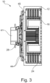
- Fig. 3 shows a schematic illustration showing a third overview of the disclosed arrangement 10 of Fig. 1 or Fig. 2 , whereby it further shows a release bearing 41, rivets 43, pivots 44 and a apply ring 45.
- the rivets 43 attach the spring unit 28 and its pivots 44 to a clutch carrier of the clutch arrangement 10 and the spring unit 28 applies the load to the apply ring 45, which compresses the friction pack comprises the five friction units 14 and six pressure units 18.
- the release bearing is actuated and the gap 26 is created between the spring unit 28 and the apply ring 45.
- the five first separator means 22 between the five pressure units 18 will push the apply ring 45 back.
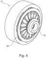
- Fig. 4 is a schematic illustration showing a fourth overview of the disclosed arrangement 10 of Fig. 1 to 3 .
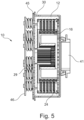
- Fig. 5 shows a schematic illustration showing an overview of a second implementation of the disclosed arrangement 10 of Fig. 1 to 3 , whereby, in contrast, the clutch arrangement 10 comprises seven spring elements 29, which are arranged to the clutch arrangement 10 with a spring cover 46.
- the clutch the clutch arrangement 10 comprises an actuating element 30, whereby the actuating element 30 comprises at least one coating material that prevents the build-up of hysteresis.
- Fig. 6 shows a schematic illustration showing a first overview of the disclosed arrangement 10 with an actuating element 30 of Fig. 5 , whereby actuating element 30 covers a clutch carrier of the clutch arrangement 10.
- the actuating element 30 may comprises a low friction coating material to prevent a hysteresis to build up, whereby parts of the clutch carrier outer diameter would have a step machined. This is to avoid the actuator to get stuck at high speeds due to deformation of the clutch carrier.
- Fig. 7 shows a schematic illustration showing a second overview of the disclosed arrangement 10 with an actuating element 30 of Fig. 5 .
Landscapes
- Engineering & Computer Science (AREA)
- General Engineering & Computer Science (AREA)
- Mechanical Engineering (AREA)
- Mechanical Operated Clutches (AREA)
Abstract
Description
- The present disclosure relates to a clutch arrangement for a vehicle, a vehicle for route planning, a vehicle with a clutch arrangement and/or a use of a shim means in a clutch arrangement.
- Known clutch arrangements comprise either wet clutches, which due to their frictional properties help to avoid NVH vibration effects during shifting, whereby typically high losses occur due to drag torques caused by viscous coupling through the oil between the moving elements. Alternatively, dry clutch arrangements are possible using, for example, organic friction material whereby NVH effects such as vibration harshness effects and/or noise harshness effects occur due to the friction material.
- In the proposed concepts, the material is used in a multi-plate design whereby another source of loss is actuation, with most of these multi-plate clutch packs requiring a constant applied force to transmit torque. This consumes energy, but also results in bearing losses due to axial force.
- In view of this, it is found that a further need exists to provide an improved clutch arrangement for a vehicle.
- In the view of the above, it is an object of the present disclosure to provide an improved clutch arrangement for a vehicle.
- The problem is at least partially solved or alleviated by the subject matter of the independent claims of the present disclosure, whereby further examples are incorporated in the dependent claims.
- According to a first aspect, a clutch arrangement for a vehicle is disclosed, comprising: a first rotating means with at least one friction unit and a second rotating means with at least one pressure unit; whereby the at least one friction unit is configured to be moved between an opened position and a closed position, whereby in the closed position, a force is transmitted between the first rotating means and the second rotating means and whereby in the opened position, no force is transmitted between the first rotating means and the second rotating means; at least one shim means arranged at the first rotating means, whereby the shim means are configured to prevent a contact between the friction unit and the pressure unit, if the friction unit is located in the opened position.
- The first rotating means and/or the second rotating means may be an element configured to rotate about a first axis and/or a second axis. Further, the first rotating means and the second rotating means may be arranged in order to rotate about the same axis.
- The at least one friction unit may be an element configured to absorb and/or transmit friction, for example, the element may be configured as a friction disk.
- The at least one pressure unit may be an element configured to absorb and/or transmit pressure, for example, the element may be configured as a pressure plate.
- The at least one shim means may be an element configured to position the at least one friction unit such that no contact occurs between the friction unit and the pressure unit in the open position.
- Moreover, in the closed position, a force is transmitted between the at least one friction unit of the first rotating means and the at least one pressure unit of the second rotating means and whereby in the opened position, no force is transmitted between the at least one friction unit of the first rotating means and the at least one pressure unit of the second rotating means.
- Furthermore, the at least one shim means may be configured to prevent impacts between the at least one friction unit and the at least one pressure unit when the clutch arrangement is in the opened position. In other words, the at least one shim means may be configured to prevent the at least one friction unit and the at least one pressure unit from freely impacting each other if the clutch arrangement is open.
- As a result, but not limited to, by using the disclosed clutch arrangement for example, the drag loss due to the usage of wet clutch arrangements may be avoided, as well as NVH effects of known dry clutch arrangement, such as in particular vibration harshness effects and/or noise harshness effects. Here, for example, the NVH effects may be reduced by arranging the at least one friction unit and/or the at least one pressure unit separately from each other and defining the relative position between the at least one friction unit and the at least one pressure unit with the at least one shim means.
- In an implementation, the clutch arrangement may comprise two or more friction units and two or more pressure units, preferably five friction units and five pressure units.
- Therefore, the clutch arrangement may for example be configured as a multidisc clutch or multi-plate clutch.
- Thereby, the at least one shim means may for example arrange a first friction unit opposite a first pressure unit opposite a second friction unit and so on.
- The arrangement with the shim means may, for example, prevent the five friction units and five pressure units from colliding with each other, thus achieving improved NVH compared to regular clutch arrangements or multi clutch arrangements.
- In an implementation, the clutch arrangement may further comprise at least one first separator means located between two pressure units and configured to position the two pressure units apart from each other.
- The at least one first separator means may be an element configured to position the two pressure units apart from each other, for example, the element is configured as a separator spring.
- In other words, the separator spring may arrange the pressure units with a controlled gap between each other to may be reduce the drag in the clutch arrangement.
- Furthermore, the gap may be divided by the force and tolerance of the plates and/or the separator spring.
- In an implementation, the clutch arrangement may further comprise at least one second separator means configured to position the two friction units apart from each other.
- The at least one second separator means may be an element configured to position the two friction units apart from each other, for example, the element is configured as a snap ring.
- In an implementation, the at least one shim means and/or the at least one second separator means may be configured to provide a gap between the at least one friction unit and the at least one pressure means.
- In other words, the at least one first separator means may form the friction units into a first block and the pressure units into a second block, whereby the at least one shim means and the at least one second separator means may create a relative position between the first block and the second block.
- Furthermore, the gap may prevent drag torque in the clutch arrangement.
- In an implementation, the clutch arrangement may be a normally closed clutch, i.e. a clutch arrangement, which is configured to be initially in the closed position. In other words, a clutch arrangement, which may be configured to be s so called closed clutch, which is initially in the closed position.
- For example, the clutch arrangement may be predefined in the closed position to transmit a force between the first rotating means and the second rotating means, and the coupling arrangement may be configured such that no force has to be applied or introduced to the coupling arrangement in order to maintain it in the predefined closed position. In addition, the clutch arrangement may be configured to apply or include a force to the clutch arrangement in order to move the clutch arrangement to the open position.
- For example, a normally closed clutch may be affected by a normally closed force, which keeps the normally closed clutch in the closed position. The normally closed force may for example be provided by a spring element and thus counteract an opening of the normally closed clutch. The normally closed clutch may for example be configured in the closed position to transmit a drive force.
- Furthermore, in order to open a normally closed clutch, an opening force may be applied which may counteract the normally closed force and may be higher than the normally closed force.
- Therefore, for example, the normally closed clutch may transmit the driving force without an actuating force being applied, whereby in order to shift the normally closed clutch from the closed position to the open position, an actuating force in the form of the opening force may be applied.
- In other words, a normally closed clutch may provide the advantage of not consuming actuation power when closed and therefore it may be beneficially for the use in a two-speed electronically axle, since the two-speed electronically axle may always be driven in one of the speeds.
- In an implementation, the clutch arrangement may further comprise at least one spring unit for holding the clutch arrangement in a closed position.
- The at least one spring unit may be configured to generate a spring force, for example it may be configured as a disc spring or diaphragm spring.
- In other words, the disk spring may be arranged at the rear of a clutch carrier of the clutch arrangement, whereby a tab of an application ring is guided through slots at the rear of the clutch carrier. As a result, a constant clamping force may be applied to the friction system through slots on the clutch carrier, whereby when released, the diaphragm spring returns to its position.
- Further, the at least one spring unit may be located at the back side of the clutch carrier due to higher stiffness of the backside.
- In an implementation, the spring unit may comprise two or more spring elements.
- The spring unit with two or more spring elements may be a configured as a coil spring unit.
- The two or more spring elements may provide the benefit of a larger gap between the at least on friction unit and the at least on pressure unit due to the arrangement of the springs around the rivets at the back the clutch carrier and the apply ring. As further, there may be less trade-off between load and travel of the springs.
- Furthermore, the two or more springs may provide a monotonically increasing load vs displacement characteristic which may lead to a better controllability of the clutch arrangement.
- In addition, the clutch arrangement may not require thrust bearings since each rotating member is constrained on its shaft and any force reaction occurs at the gearbox bearings, whereby a load on the clutch arrangement may be reduced if a lever ratio is provided to reduce the load. This may minimize an axial force application to gearbox bearings, which also leads to a reduction of the generated losses.
- In an implementation, the clutch arrangement may further comprise an actuating element.
- The actuating element may be a cover of the clutch arrangement and/or parts of the clutch arrangement.
- In an implementation, the actuating element may comprise at least one coating material that prevents the build-up of hysteresis.
- The actuating element may comprise a low friction coating material between the carrier and the actuator to prevent hysteresis to build up.
- In an implementation, the at least one spring unit and/or the actuating element may be arranged to the second rotating means.
- In an implementation, the clutch arrangement is may further comprise at least one concentric shaft on which the first rotating means and/or the second rotating means is/are arranged.
- The concentric shaft may be configured to carry clutch input member and/or clutch output member, so that thrust bearings, for example, are not needed for the use of the clutch arrangement. In addition, the force required to actuate the clutch arrangement may be reduced by the lever ratio of the at least one spring unit.
- Therefore, forces to actuate the clutch assembly may also be reduced since thrust bearings are not required and/or lower actuation forces may reduce losses at the shaft bearings if the clutch is connected to the shaft.
- A further aspect of the present disclosure relates to a vehicle comprising the at least one disclosed clutch arrangement.
- Vehicle may be broadly understood and construed whereby it may comprise, but is not limited to, automobiles and/or aircraft, as well as other vehicles that utilize a clutch arrangement.
- A further aspect of the present disclosure relates to a use of the at least one disclosed shim means in the disclosed clutch arrangement.
- In the following, the disclosure is described exemplarily with reference to the enclosed figures, in which:
- Fig. 1
- is a schematic illustration showing a first overview of the disclosed arrangement in a system;
- Fig. 2
- is a schematic illustration showing a second overview of the disclosed system;
- Fig. 3
- is a schematic illustration showing a third overview of the disclosed arrangement;
- Fig. 4
- is a schematic illustration showing a fourth overview of the disclosed arrangement;
- Fig. 5
- is a schematic illustration showing an overview of a second implementation of the disclosed arrangement;
- Fig. 6
- is a schematic illustration showing a first overview of the disclosed arrangement with an actuating element; and
- Fig. 7
- is a schematic illustration showing a second overview of the second implementation of the disclosed arrangement with an actuating element.
- Notably, the figures are merely schematic representations and serve only to illustrate examples of the present disclosure. Identical or equivalent elements are in principle provided with the same reference signs.
-
Fig. 1 andFig. 2 shows a schematic illustration showing a first and second overview of the disclosedclutch arrangement 10 in a system, comprising: a first rotating means 12 with fivefriction units 14 and a second rotating means 16 with sixpressure units 18; whereby the fivefriction units 14 are configured to be moved between an opened position and a closed position, whereby in the closed position, a force is transmitted between the firstrotating means 12 and the secondrotating means 16 and whereby in the opened position, no force is transmitted between the firstrotating means 12 and the second rotating means 16; ten shim means 19 arranged at the first rotating means, whereby the ten shim means 19 are configured to prevent a contact between the fivefriction units 14 and the sixpressure units 18, if the fivefriction units 14 are located in the opened position. - In addition, the ten shim means 19 are connected and/or fixed to the first
rotating means 12 by means of holdingunits 24. - Further, the
clutch arrangement 10 comprises five first separator means 22 located between the sixpressure units 18 and configured to position the fivepressure units 18 apart from each other. - Further, the
clutch arrangement 10 comprises a second separator means 20 configured to position the fivefriction units 14 apart from each other. - Further, whereby the ten shim means 19 and/or the second separator means 20 are configured to provide a
gap 26 between the fivefriction unit 14 and the sixpressure unit 18. - Further, the
clutch arrangement 10 is a normally closed clutch, which is initially in the closed position. - Further, the
clutch arrangement 10 is further comprising at least onespring unit 28 for holding theclutch arrangement 10 in a closed position. - Further, the
clutch arrangement 10 comprises at least oneconcentric shaft 34 on which the firstrotating means 12 and/or the secondrotating means 16 is/are arranged. - Further, the at least one
spring unit 28 is arranged to the secondrotating means 16. - Moreover a clutch piston 40, a release bearing 41 and clutch input and
output members 42 are shown, whereby the clutch input andoutput members 42 are tightened to theconcentric shafts 34 to reduce number of bearings and reduce loses. -
Fig. 3 shows a schematic illustration showing a third overview of the disclosedarrangement 10 ofFig. 1 orFig. 2 , whereby it further shows a release bearing 41, rivets 43, pivots 44 and a applyring 45. - Furthermore, the rivets 43 attach the
spring unit 28 and itspivots 44 to a clutch carrier of theclutch arrangement 10 and thespring unit 28 applies the load to the applyring 45, which compresses the friction pack comprises the fivefriction units 14 and sixpressure units 18. - Therefore, to release the
clutch arrangement 10, the release bearing is actuated and thegap 26 is created between thespring unit 28 and the applyring 45. The five first separator means 22 between the fivepressure units 18 will push the applyring 45 back. -
Fig. 4 is a schematic illustration showing a fourth overview of the disclosedarrangement 10 ofFig. 1 to 3 . -
Fig. 5 shows a schematic illustration showing an overview of a second implementation of the disclosedarrangement 10 ofFig. 1 to 3 , whereby, in contrast, theclutch arrangement 10 comprises sevenspring elements 29, which are arranged to theclutch arrangement 10 with aspring cover 46. - Furthermore, the clutch the
clutch arrangement 10 comprises anactuating element 30, whereby theactuating element 30 comprises at least one coating material that prevents the build-up of hysteresis. - Further, whereby the
actuating element 30 is arranged to the secondrotating means 16. -
Fig. 6 shows a schematic illustration showing a first overview of the disclosedarrangement 10 with anactuating element 30 ofFig. 5 , whereby actuatingelement 30 covers a clutch carrier of theclutch arrangement 10. - Furthermore, the
actuating element 30 may comprises a low friction coating material to prevent a hysteresis to build up, whereby parts of the clutch carrier outer diameter would have a step machined. This is to avoid the actuator to get stuck at high speeds due to deformation of the clutch carrier. -
Fig. 7 shows a schematic illustration showing a second overview of the disclosedarrangement 10 with anactuating element 30 ofFig. 5 . - Other variations to the disclosed examples may be understood and effected by those skilled in the art in practicing the claimed subject matter, from the study of the figures, the disclosure, and the appended claims. In particular, respective parts/functions of the respective example described above may also be combined with each other. In particular, the present disclosure is not limited to specific modules, vehicle functions, user interfaces, user interface areas/fields and/or communication methods. In the claims, the word "comprising" does not exclude other elements or steps and the indefinite article "a" or "an" does not exclude a plurality. The mere fact that certain measures are recited in mutually different dependent claims does not indicate that a combination of these measures may not be used to advantage. Any reference signs in the claims should not be construed as limiting the scope of the claims.
-
- 10
- Clutch arrangement
- 12
- first rotating means
- 14
- at least one friction unit
- 16
- second rotating means
- 18
- at least one pressure unit
- 19
- shim means
- 20
- at least one second separator means
- 22
- at least one first separator means
- 24
- holding unit
- 26
- gap
- 28
- at least one spring unit
- 29
- spring elements
- 30
- actuating element
- 34
- concentric shaft
- 40
- clutch piston
- 41
- release bearing
- 42
- clutch input and output members
- 44
- pivots
- 45
- apply ring
- 46
- spring cover
Claims (14)
- Clutch arrangement for a vehicle, comprising:a first rotating means (12) with at least one friction unit (14) and a second rotating means (16) with at least one pressure unit (18);whereby the at least one friction unit (14) is configured to be moved between an opened position and a closed position, whereby in the closed position, a force is transmitted between the first rotating means (12) and the second rotating means (16) and whereby in the opened position, no force is transmitted between the first rotating means (12) and the second rotating means (16);at least one shim means (19) arranged at the first rotating means (12), whereby the shim means (19) are configured to prevent a contact between the friction unit (14) and the pressure unit (18), if the friction unit (14) is in the opened position.
- The clutch arrangement according to claim 1, whereby the clutch arrangement (10) comprises two or more friction units (14) and two or more pressure units (18), preferably five friction units (14) and five pressure units (18).
- The clutch arrangement according to claim 2, whereby the clutch arrangement (10) is further comprising at least one first separator means (22) located between two pressure units (18) and configured to position the two pressure units (18) apart from each other.
- The clutch arrangement according to claim 2 or claim 3, whereby the clutch arrangement (10) is further comprising at least one second separator means (20) configured to position the two friction units (14) apart from each other.
- The clutch arrangement according to any one of the preceding claims, whereby the at least one shim means (19) and/or the at least one second separator means (20) are configured to provide a gap (26) between the at least one friction unit (14) and the at least one pressure unit (18).
- The clutch arrangement according to any one of the preceding claims, whereby the clutch arrangement (10) is configured to be a closed clutch, which is initially in the closed position.
- The clutch arrangement according to claim 6, whereby the clutch arrangement (10) is further comprising at least one spring unit (28) for holding the clutch arrangement (10) in a closed position.
- The clutch arrangement according to claim 7, whereby the spring unit (28) comprises two or more spring elements (29).
- The clutch arrangement according to any one of the preceding claims, whereby the clutch arrangement (10) is further comprising an actuating element (30).
- The clutch arrangement according to claim 9, whereby the actuating element (30) comprises at least one coating material that prevents the build-up of hysteresis.
- The clutch arrangement according to any one of the preceding claims, whereby the at least one spring unit (28) and/or the actuating element (30) is/are arranged to the second rotating means (16).
- The clutch arrangement according to any one of the preceding claims, whereby the clutch arrangement (10) is further comprising at least one concentric shaft (34) on which the first rotating means (12) and/or the second rotating means (16) is/are arranged.
- Vehicle comprising at least one clutch arrangement according to any one of the preceding claims.
- Use of at least one shim means in a clutch arrangement according to any one of the claims 1 to 12.
Priority Applications (3)
| Application Number | Priority Date | Filing Date | Title |
|---|---|---|---|
| EP23164348.7A EP4438916B1 (en) | 2023-03-27 | 2023-03-27 | Improved friction clutch system |
| US18/618,289 US12553477B2 (en) | 2023-03-27 | 2024-03-27 | Friction clutch system |
| CN202410356187.2A CN118705289A (en) | 2023-03-27 | 2024-03-27 | Improved friction clutch system |
Applications Claiming Priority (1)
| Application Number | Priority Date | Filing Date | Title |
|---|---|---|---|
| EP23164348.7A EP4438916B1 (en) | 2023-03-27 | 2023-03-27 | Improved friction clutch system |
Publications (2)
| Publication Number | Publication Date |
|---|---|
| EP4438916A1 true EP4438916A1 (en) | 2024-10-02 |
| EP4438916B1 EP4438916B1 (en) | 2025-10-08 |
Family
ID=85775959
Family Applications (1)
| Application Number | Title | Priority Date | Filing Date |
|---|---|---|---|
| EP23164348.7A Active EP4438916B1 (en) | 2023-03-27 | 2023-03-27 | Improved friction clutch system |
Country Status (3)
| Country | Link |
|---|---|
| US (1) | US12553477B2 (en) |
| EP (1) | EP4438916B1 (en) |
| CN (1) | CN118705289A (en) |
Citations (6)
| Publication number | Priority date | Publication date | Assignee | Title |
|---|---|---|---|---|
| US4676356A (en) * | 1983-10-18 | 1987-06-30 | Valeo | Multiple rotating disk assembly with elastic separator means |
| US8162119B2 (en) * | 2008-04-03 | 2012-04-24 | Kawasaki Jukogyo Kabushiki Kaisha | Back torque reducing device of a friction clutch and motorcycle comprising the same |
| US8272489B2 (en) * | 2008-09-30 | 2012-09-25 | Honda Motor Co., Ltd. | Multiple disc clutch |
| US10837499B2 (en) * | 2018-03-14 | 2020-11-17 | Exedy Corporation | Clutch device |
| US20220221009A1 (en) * | 2019-05-17 | 2022-07-14 | Transmisiones Y Equipos Mecanicos, S.A. De Cv | Double clutch unit in a transmission |
| US11401980B2 (en) * | 2018-11-28 | 2022-08-02 | Kabushiki Kaisha F.C.C. | Wet friction plate, wet multi-plate clutch device provided with same wet friction plate, and method for manufacturing wet friction plate |
Family Cites Families (5)
| Publication number | Priority date | Publication date | Assignee | Title |
|---|---|---|---|---|
| JP3020054B2 (en) * | 1998-03-25 | 2000-03-15 | 新日本ホイール工業株式会社 | Multi-plate friction clutch |
| US6543596B2 (en) * | 2000-04-24 | 2003-04-08 | Borgwarner, Inc. | Multi-disk friction device having low-drag characteristics |
| US8640842B2 (en) * | 2011-03-09 | 2014-02-04 | American Axle & Manufacturing, Inc. | Clutch plate having integrated separating feature |
| US9915007B2 (en) * | 2015-06-29 | 2018-03-13 | GM Global Technology Operations LLC | Electro ceramic coated aluminum transmission components |
| DE102015216731A1 (en) * | 2015-09-02 | 2017-03-02 | Zf Friedrichshafen Ag | clutch assembly |
-
2023
- 2023-03-27 EP EP23164348.7A patent/EP4438916B1/en active Active
-
2024
- 2024-03-27 CN CN202410356187.2A patent/CN118705289A/en active Pending
- 2024-03-27 US US18/618,289 patent/US12553477B2/en active Active
Patent Citations (6)
| Publication number | Priority date | Publication date | Assignee | Title |
|---|---|---|---|---|
| US4676356A (en) * | 1983-10-18 | 1987-06-30 | Valeo | Multiple rotating disk assembly with elastic separator means |
| US8162119B2 (en) * | 2008-04-03 | 2012-04-24 | Kawasaki Jukogyo Kabushiki Kaisha | Back torque reducing device of a friction clutch and motorcycle comprising the same |
| US8272489B2 (en) * | 2008-09-30 | 2012-09-25 | Honda Motor Co., Ltd. | Multiple disc clutch |
| US10837499B2 (en) * | 2018-03-14 | 2020-11-17 | Exedy Corporation | Clutch device |
| US11401980B2 (en) * | 2018-11-28 | 2022-08-02 | Kabushiki Kaisha F.C.C. | Wet friction plate, wet multi-plate clutch device provided with same wet friction plate, and method for manufacturing wet friction plate |
| US20220221009A1 (en) * | 2019-05-17 | 2022-07-14 | Transmisiones Y Equipos Mecanicos, S.A. De Cv | Double clutch unit in a transmission |
Also Published As
| Publication number | Publication date |
|---|---|
| CN118705289A (en) | 2024-09-27 |
| US12553477B2 (en) | 2026-02-17 |
| EP4438916B1 (en) | 2025-10-08 |
| US20240328466A1 (en) | 2024-10-03 |
Similar Documents
| Publication | Publication Date | Title |
|---|---|---|
| US10882388B2 (en) | Internal combustion engine decoupling device of a PHEV transmission unit | |
| US6401894B1 (en) | Multiple-clutch assembly | |
| EP3919304B1 (en) | Electric vehicle powertrain assembly having nested shafts | |
| CN102227573A (en) | Multiple clutch device | |
| US10837525B2 (en) | Motor vehicle transmission | |
| CN104334904A (en) | Friction engagement device | |
| US8276727B2 (en) | Dual clutch | |
| US7431138B2 (en) | Start-up clutch assembly | |
| EP3543556A1 (en) | Triple clutch and actuator thereof | |
| CN111043179A (en) | Inner friction lining carrier, wet-running friction clutch and drive train unit | |
| CN113614405B (en) | Multi-plate clutch with optimized shifting friction; hybrid module, dual clutch arrangement and powertrain | |
| CN111263862A (en) | Multiple clutch device and hybrid module for a motor vehicle | |
| KR20180116936A (en) | Double clutch system for hybrid electric vehicles | |
| US20050155826A1 (en) | Friction engaging device | |
| US20050137044A1 (en) | Multiple speed automatic transmission for motor vehicle | |
| US20040238314A1 (en) | Tandem frictional engagement device and automatic transmission mounted therewith | |
| KR101155646B1 (en) | Clutch and automatic transmission provided with the same | |
| US4834229A (en) | Fluid operated multiple-disk friction clutch | |
| EP4438916B1 (en) | Improved friction clutch system | |
| US20250334155A1 (en) | Clutch device | |
| CN113446326A (en) | Clutch assembly pressure plate with conical surface | |
| US12031590B2 (en) | Pressure medium-actuated separating clutch which is normally closed, comprising an actuation device which rotates therewith and axially overlaps with a damper device | |
| CN111623048A (en) | Clutch with leaf spring elements for spacing apart plates or clutch discs | |
| CN212479953U (en) | Double-input shaft membrane spring parallel type double clutch | |
| CN212479954U (en) | Double-input-shaft single-output-shaft membrane spring type double clutch |
Legal Events
| Date | Code | Title | Description |
|---|---|---|---|
| STAA | Information on the status of an ep patent application or granted ep patent |
Free format text: STATUS: EXAMINATION IS IN PROGRESS |
|
| PUAI | Public reference made under article 153(3) epc to a published international application that has entered the european phase |
Free format text: ORIGINAL CODE: 0009012 |
|
| 17P | Request for examination filed |
Effective date: 20231129 |
|
| AK | Designated contracting states |
Kind code of ref document: A1 Designated state(s): AL AT BE BG CH CY CZ DE DK EE ES FI FR GB GR HR HU IE IS IT LI LT LU LV MC ME MK MT NL NO PL PT RO RS SE SI SK SM TR |
|
| GRAP | Despatch of communication of intention to grant a patent |
Free format text: ORIGINAL CODE: EPIDOSNIGR1 |
|
| STAA | Information on the status of an ep patent application or granted ep patent |
Free format text: STATUS: GRANT OF PATENT IS INTENDED |
|
| INTG | Intention to grant announced |
Effective date: 20250605 |
|
| GRAS | Grant fee paid |
Free format text: ORIGINAL CODE: EPIDOSNIGR3 |
|
| GRAA | (expected) grant |
Free format text: ORIGINAL CODE: 0009210 |
|
| STAA | Information on the status of an ep patent application or granted ep patent |
Free format text: STATUS: THE PATENT HAS BEEN GRANTED |
|
| AK | Designated contracting states |
Kind code of ref document: B1 Designated state(s): AL AT BE BG CH CY CZ DE DK EE ES FI FR GB GR HR HU IE IS IT LI LT LU LV MC ME MK MT NL NO PL PT RO RS SE SI SK SM TR |
|
| REG | Reference to a national code |
Ref country code: GB Ref legal event code: FG4D Ref country code: CH Ref legal event code: F10 Free format text: ST27 STATUS EVENT CODE: U-0-0-F10-F00 (AS PROVIDED BY THE NATIONAL OFFICE) Effective date: 20251008 |
|
| REG | Reference to a national code |
Ref country code: DE Ref legal event code: R096 Ref document number: 602023007233 Country of ref document: DE |
|
| REG | Reference to a national code |
Ref country code: IE Ref legal event code: FG4D |
|
| P01 | Opt-out of the competence of the unified patent court (upc) registered |
Free format text: CASE NUMBER: UPC_APP_9198_4438916/2025 Effective date: 20251007 |
|
| REG | Reference to a national code |
Ref country code: NL Ref legal event code: MP Effective date: 20251008 |
|
| REG | Reference to a national code |
Ref country code: AT Ref legal event code: MK05 Ref document number: 1845023 Country of ref document: AT Kind code of ref document: T Effective date: 20251008 |
|
| PG25 | Lapsed in a contracting state [announced via postgrant information from national office to epo] |
Ref country code: NL Free format text: LAPSE BECAUSE OF FAILURE TO SUBMIT A TRANSLATION OF THE DESCRIPTION OR TO PAY THE FEE WITHIN THE PRESCRIBED TIME-LIMIT Effective date: 20251008 |
|
| PG25 | Lapsed in a contracting state [announced via postgrant information from national office to epo] |
Ref country code: ES Free format text: LAPSE BECAUSE OF FAILURE TO SUBMIT A TRANSLATION OF THE DESCRIPTION OR TO PAY THE FEE WITHIN THE PRESCRIBED TIME-LIMIT Effective date: 20251008 |
|
| REG | Reference to a national code |
Ref country code: LT Ref legal event code: MG9D |
|
| PG25 | Lapsed in a contracting state [announced via postgrant information from national office to epo] |
Ref country code: NO Free format text: LAPSE BECAUSE OF FAILURE TO SUBMIT A TRANSLATION OF THE DESCRIPTION OR TO PAY THE FEE WITHIN THE PRESCRIBED TIME-LIMIT Effective date: 20260108 |
|
| PGFP | Annual fee paid to national office [announced via postgrant information from national office to epo] |
Ref country code: DE Payment date: 20260219 Year of fee payment: 4 |
|
| PG25 | Lapsed in a contracting state [announced via postgrant information from national office to epo] |
Ref country code: HR Free format text: LAPSE BECAUSE OF FAILURE TO SUBMIT A TRANSLATION OF THE DESCRIPTION OR TO PAY THE FEE WITHIN THE PRESCRIBED TIME-LIMIT Effective date: 20251008 Ref country code: FI Free format text: LAPSE BECAUSE OF FAILURE TO SUBMIT A TRANSLATION OF THE DESCRIPTION OR TO PAY THE FEE WITHIN THE PRESCRIBED TIME-LIMIT Effective date: 20251008 Ref country code: AT Free format text: LAPSE BECAUSE OF FAILURE TO SUBMIT A TRANSLATION OF THE DESCRIPTION OR TO PAY THE FEE WITHIN THE PRESCRIBED TIME-LIMIT Effective date: 20251008 |
|
| PG25 | Lapsed in a contracting state [announced via postgrant information from national office to epo] |
Ref country code: RS Free format text: LAPSE BECAUSE OF FAILURE TO SUBMIT A TRANSLATION OF THE DESCRIPTION OR TO PAY THE FEE WITHIN THE PRESCRIBED TIME-LIMIT Effective date: 20260108 |
|
| PG25 | Lapsed in a contracting state [announced via postgrant information from national office to epo] |
Ref country code: IS Free format text: LAPSE BECAUSE OF FAILURE TO SUBMIT A TRANSLATION OF THE DESCRIPTION OR TO PAY THE FEE WITHIN THE PRESCRIBED TIME-LIMIT Effective date: 20260208 |
|
| PGFP | Annual fee paid to national office [announced via postgrant information from national office to epo] |
Ref country code: FR Payment date: 20260219 Year of fee payment: 4 |
|
| PG25 | Lapsed in a contracting state [announced via postgrant information from national office to epo] |
Ref country code: PT Free format text: LAPSE BECAUSE OF FAILURE TO SUBMIT A TRANSLATION OF THE DESCRIPTION OR TO PAY THE FEE WITHIN THE PRESCRIBED TIME-LIMIT Effective date: 20260209 |
|
| PG25 | Lapsed in a contracting state [announced via postgrant information from national office to epo] |
Ref country code: PL Free format text: LAPSE BECAUSE OF FAILURE TO SUBMIT A TRANSLATION OF THE DESCRIPTION OR TO PAY THE FEE WITHIN THE PRESCRIBED TIME-LIMIT Effective date: 20251008 |
|
| PG25 | Lapsed in a contracting state [announced via postgrant information from national office to epo] |
Ref country code: LV Free format text: LAPSE BECAUSE OF FAILURE TO SUBMIT A TRANSLATION OF THE DESCRIPTION OR TO PAY THE FEE WITHIN THE PRESCRIBED TIME-LIMIT Effective date: 20251008 |
|
| PG25 | Lapsed in a contracting state [announced via postgrant information from national office to epo] |
Ref country code: BG Free format text: LAPSE BECAUSE OF FAILURE TO SUBMIT A TRANSLATION OF THE DESCRIPTION OR TO PAY THE FEE WITHIN THE PRESCRIBED TIME-LIMIT Effective date: 20251008 |