EP4438904A1 - Vacuum pump and control device - Google Patents
Vacuum pump and control device Download PDFInfo
- Publication number
- EP4438904A1 EP4438904A1 EP22898633.7A EP22898633A EP4438904A1 EP 4438904 A1 EP4438904 A1 EP 4438904A1 EP 22898633 A EP22898633 A EP 22898633A EP 4438904 A1 EP4438904 A1 EP 4438904A1
- Authority
- EP
- European Patent Office
- Prior art keywords
- circuit
- vacuum pump
- control circuit
- communication
- slave
- Prior art date
- Legal status (The legal status is an assumption and is not a legal conclusion. Google has not performed a legal analysis and makes no representation as to the accuracy of the status listed.)
- Pending
Links
Images



Classifications
-
- F—MECHANICAL ENGINEERING; LIGHTING; HEATING; WEAPONS; BLASTING
- F04—POSITIVE - DISPLACEMENT MACHINES FOR LIQUIDS; PUMPS FOR LIQUIDS OR ELASTIC FLUIDS
- F04D—NON-POSITIVE-DISPLACEMENT PUMPS
- F04D27/00—Control, e.g. regulation, of pumps, pumping installations or pumping systems specially adapted for elastic fluids
- F04D27/008—Stop safety or alarm devices, e.g. stop-and-go control; Disposition of check-valves
-
- F—MECHANICAL ENGINEERING; LIGHTING; HEATING; WEAPONS; BLASTING
- F04—POSITIVE - DISPLACEMENT MACHINES FOR LIQUIDS; PUMPS FOR LIQUIDS OR ELASTIC FLUIDS
- F04D—NON-POSITIVE-DISPLACEMENT PUMPS
- F04D19/00—Axial-flow pumps
- F04D19/02—Multi-stage pumps
- F04D19/04—Multi-stage pumps specially adapted to the production of a high vacuum, e.g. molecular pumps
-
- F—MECHANICAL ENGINEERING; LIGHTING; HEATING; WEAPONS; BLASTING
- F04—POSITIVE - DISPLACEMENT MACHINES FOR LIQUIDS; PUMPS FOR LIQUIDS OR ELASTIC FLUIDS
- F04D—NON-POSITIVE-DISPLACEMENT PUMPS
- F04D19/00—Axial-flow pumps
- F04D19/02—Multi-stage pumps
- F04D19/04—Multi-stage pumps specially adapted to the production of a high vacuum, e.g. molecular pumps
- F04D19/042—Turbomolecular vacuum pumps
-
- F—MECHANICAL ENGINEERING; LIGHTING; HEATING; WEAPONS; BLASTING
- F04—POSITIVE - DISPLACEMENT MACHINES FOR LIQUIDS; PUMPS FOR LIQUIDS OR ELASTIC FLUIDS
- F04D—NON-POSITIVE-DISPLACEMENT PUMPS
- F04D27/00—Control, e.g. regulation, of pumps, pumping installations or pumping systems specially adapted for elastic fluids
- F04D27/001—Testing thereof; Determination or simulation of flow characteristics; Stall or surge detection, e.g. condition monitoring
-
- F—MECHANICAL ENGINEERING; LIGHTING; HEATING; WEAPONS; BLASTING
- F04—POSITIVE - DISPLACEMENT MACHINES FOR LIQUIDS; PUMPS FOR LIQUIDS OR ELASTIC FLUIDS
- F04D—NON-POSITIVE-DISPLACEMENT PUMPS
- F04D27/00—Control, e.g. regulation, of pumps, pumping installations or pumping systems specially adapted for elastic fluids
- F04D27/02—Surge control
- F04D27/0292—Stop safety or alarm devices, e.g. stop-and-go control; Disposition of check-valves
-
- F—MECHANICAL ENGINEERING; LIGHTING; HEATING; WEAPONS; BLASTING
- F05—INDEXING SCHEMES RELATING TO ENGINES OR PUMPS IN VARIOUS SUBCLASSES OF CLASSES F01-F04
- F05D—INDEXING SCHEME FOR ASPECTS RELATING TO NON-POSITIVE-DISPLACEMENT MACHINES OR ENGINES, GAS-TURBINES OR JET-PROPULSION PLANTS
- F05D2260/00—Function
- F05D2260/80—Diagnostics
-
- F—MECHANICAL ENGINEERING; LIGHTING; HEATING; WEAPONS; BLASTING
- F05—INDEXING SCHEMES RELATING TO ENGINES OR PUMPS IN VARIOUS SUBCLASSES OF CLASSES F01-F04
- F05D—INDEXING SCHEME FOR ASPECTS RELATING TO NON-POSITIVE-DISPLACEMENT MACHINES OR ENGINES, GAS-TURBINES OR JET-PROPULSION PLANTS
- F05D2260/00—Function
- F05D2260/82—Forecasts
- F05D2260/821—Parameter estimation or prediction
Definitions
- the present invention relates to a vacuum pump and a controller used for the vacuum pump.
- Vacuum pumps are used in apparatuses such as semiconductor manufacturing apparatuses, electron microscopes, and mass spectrometers to produce high vacuums in vacuum chambers.
- apparatuses such as semiconductor manufacturing apparatuses, electron microscopes, and mass spectrometers to produce high vacuums in vacuum chambers.
- turbomolecular pumps in particular, are widely used for reasons such as less residual gas and easy maintenance.
- a turbomolecular pump includes a rotor shaft having an outer circumference surface on which rotor blades are arranged in multiple stages.
- This rotor shaft is rotatably supported in a casing.
- Stator blades are arranged in multiple stages on the inner circumference surface of the casing and positioned between the rotor blades.
- the rotor is rotated at high speed by a motor after the pressure in the vacuum chamber is reduced to some extent, thereby causing the rotor blades and the stator blades to collide with gas molecules.
- the gas molecules are thus given momentum and exhausted.
- This exhaust operation compresses and exhausts the gas molecules drawn from the vacuum chamber into the pump, thereby creating a predetermined high degree of vacuum in the vacuum chamber.
- the rotor shaft is rotatably supported by, for example, a magnetic bearing of 5-axis control, which suspends the rotor shaft in the air and also controls the position thereof.
- the motor includes a plurality of magnetic poles circumferentially arranged to surround the rotor shaft. The magnetic poles drive and rotate the rotor shaft by electromagnetic forces acting between the magnetic poles and the rotor shaft.
- the magnetic bearing includes electromagnets that exert electromagnetic forces on the rotor shaft.
- a magnetic bearing control circuit (the magnetic bearing control portion in PTL 1) controls these electromagnets to support the rotor shaft in a non-contact manner.
- the motor is controlled by a motor control circuit (the motor drive control portion in PTL 1) to drive and rotate the rotor shaft by the electromagnetic forces from the magnetic poles and acting between the rotor shaft and the magnetic poles.
- the magnetic bearing control circuit and the motor control circuit are connected to a control circuit (the protection function processing portion in PTL 1).
- the control circuit controls the magnetic bearing control circuit and the motor control circuit so that the operating state of the electromagnets, which is controlled by the magnetic bearing control circuit, and the operating state of the motor, which is controlled by the motor control circuit, are in preset ranges. That is, the control circuit corresponds to a "master circuit" in a master-slave system, and the magnetic bearing control circuit and the motor control circuit correspond to "slave circuits" in the master-slave control.
- the control circuit also has the function of monitoring the operating state of the electromagnets and the operating state of the motor to issue an alarm or to stop the turbomolecular pump when these operating states deviate from the preset ranges.
- the present invention includes a control means to control an operation of each of portions included in a vacuum pump.
- the control means includes a slave circuit connected to each of the portions to control the operation of each of the portions and a master circuit connected to the slave circuit to control the slave circuit.
- the master circuit is configured to perform periodical communications with the slave circuit and obtain a history of communication states of the communications.
- This vacuum pump preferably issues an alarm to an outside, based on the history of communication states.
- the alarm is preferably issued based on a total number of communication errors in a predetermined period.
- the alarm may be issued based on an occurrence ratio of communication errors in a predetermined period.
- the alarm may be issued in response to a plurality of communication errors occurring in succession.
- the history of communication states includes at least one of request content of data, response content of data, an error type, or a time of a most recent communication error.
- the present invention relates to a controller for controlling an operation of each of portions included in a vacuum pump.
- the controller includes a slave circuit connected to each of the portions to control the operation of each of the portions and a master circuit connected to the slave circuit to control the slave circuit.
- the master circuit is configured to perform periodical communications with the slave circuit and obtain a history of communication states of the communications.
- the master circuit performs periodical communications with the slave circuit and obtains a history of communication states of the communications.
- the obtained history of communication states can be used to evaluate the communication quality, thereby allowing for the identification of the noise immunities or the like of the master circuit and the slave circuit based on the evaluation.
- the identified noise immunities or the like may be used to appropriately take various measures to further improve the stability of the operation of the vacuum pump.
- turbomolecular pump 100 of an embodiment of a vacuum pump according to the present invention is now described. First, referring to FIGS. 1 to 4 , the overall configuration of the turbomolecular pump 100 is described.
- FIG. 1 is a vertical cross-sectional view of the turbomolecular pump 100.
- the turbomolecular pump 100 has a circular outer cylinder 127 having an inlet port 101 at its upper end.
- a rotating body 103 in the outer cylinder 127 includes a plurality of rotor blades 102 (102a, 102b, 102c, ...), which are turbine blades for gas suction and exhaustion, in its outer circumference section.
- the rotor blades 102 extend radially in multiple stages.
- the rotating body 103 has a rotor shaft 113 in its center.
- the rotor shaft 113 is supported and suspended in the air and position-controlled by a magnetic bearing 115 ( FIG. 5 ) of 5-axis control, for example.
- the magnetic bearing 115 includes electromagnets 104, 105, 106A, and 106B, which will be described below and shown in FIG. 1 .
- the rotating body 103 is typically made of a metal such as aluminum or an aluminum alloy
- Upper radial electromagnets 104 include four electromagnets arranged in pairs on an X-axis and a Y-axis.
- Four upper radial sensors 107 are provided in close proximity to the upper radial electromagnets 104 and associated with the respective upper radial electromagnets 104.
- Each upper radial sensor 107 may be an inductance sensor or an eddy current sensor having a conduction winding, for example, and detects the position of the rotor shaft 113 based on a change in the inductance of the conduction winding, which changes according to the position of the rotor shaft 113.
- the upper radial sensors 107 are configured to detect a radial displacement of the rotor shaft 113, that is, the rotating body 103 fixed to the rotor shaft 113, and send it to the controller 200.
- the controller (control means) 200 of the present embodiment includes a magnetic bearing control circuit 201 and a motor control circuit 202 shown in FIG. 5 .
- a compensation circuit having a PID adjustment function generates an excitation control command signal for the upper radial electromagnets 104 based on a position signal detected by the upper radial sensors 107. Based on this excitation control command signal, an amplifier circuit 150 (described below) shown in FIG. 2 controls and excites the upper radial electromagnets 104 to adjust the radial position of the upper part of the rotor shaft 113.
- the rotor shaft 113 may be made of a high magnetic permeability material (such as iron and stainless steel) and is configured to be attracted by magnetic forces of the upper radial electromagnets 104. The adjustment is performed independently in the X-axis direction and the Y-axis direction.
- Lower radial electromagnets 105 and lower radial sensors 108 are arranged in a similar manner as the upper radial electromagnets 104 and the upper radial sensors 107 to adjust the radial position of the lower part of the rotor shaft 113 in a similar manner as the radial position of the upper part.
- axial electromagnets 106A and 106B are arranged so as to vertically sandwich a metal disc 111, which has a shape of a circular disc and is provided in the lower part of the rotor shaft 113.
- the metal disc 111 is made of a high magnetic permeability material such as iron.
- An axial sensor 109 is provided to detect an axial displacement of the rotor shaft 113 and send an axial position signal to the magnetic bearing control circuit 201.
- the compensation circuit having the PID adjustment function may generate an excitation control command signal for each of the axial electromagnets 106A and 106B based on the signal on the axial position detected by the axial sensor 109. Based on these excitation control command signals, the amplifier circuit 150 controls and excites the axial electromagnets 106A and 106B separately so that the axial electromagnet 106A magnetically attracts the metal disc 111 upward and the axial electromagnet 106B attracts the metal disc 111 downward. The axial position of the rotor shaft 113 is thus adjusted.
- the magnetic bearing control circuit 201 appropriately adjusts the magnetic forces exerted by the axial electromagnets 106A and 106B on the metal disc 111, magnetically levitates the rotor shaft 113 in the axial direction, and suspends the rotor shaft 113 in the air in a non-contact manner.
- the amplifier circuit 150 which controls and excites the upper radial electromagnets 104, the lower radial electromagnets 105, and the axial electromagnets 106A and 106B, is described below.
- the motor 121 includes a plurality of magnetic poles circumferentially arranged to surround the rotor shaft 113. Each magnetic pole is controlled by the motor control circuit 202 so as to drive and rotate the rotor shaft 113 via an electromagnetic force acting between the magnetic pole and the rotor shaft 113.
- the motor 121 also includes a rotational speed sensor (not shown), such as a Hall element, a resolver, or an encoder, and the rotational speed of the rotor shaft 113 is detected based on a detection signal of the rotational speed sensor.
- phase sensor (not shown) is attached adjacent to the lower radial sensors 108 to detect the phase of rotation of the rotor shaft 113.
- the motor control circuit 200 detects the position of the magnetic poles using both detection signals of the phase sensor and the rotational speed sensor.
- a plurality of stator blades 123 (123a, 123b, 123c, ...) are arranged slightly spaced apart from the rotor blades 102 (102a, 102b, 102c, ). Each rotor blade 102 (102a, 102b, 102c, ...) is inclined by a predetermined angle from a plane perpendicular to the axis of the rotor shaft 113 in order to transfer exhaust gas molecules downward through collision.
- the stator blades 123 (123a, 123b, 123c, ...) are made of a metal such as aluminum, iron, stainless steel, copper, or a metal such as an alloy containing these metals as components.
- the stator blades 123 are also inclined by a predetermined angle from a plane perpendicular to the axis of the rotor shaft 113.
- the stator blades 123 extend inward of the outer cylinder 127 and alternate with the stages of the rotor blades 102.
- the outer circumference ends of the stator blades 123 are inserted between and thus supported by a plurality of layered stator blade spacers 125 (125a, 125b, 125c, ).
- the stator blade spacers 125 are ring-shaped members made of a metal, such as aluminum, iron, stainless steel, or copper, or an alloy containing these metals as components, for example.
- the outer cylinder 127 is fixed to the outer circumferences of the stator blade spacers 125 with a slight gap.
- a base portion 129 is located at the base of the outer cylinder 127.
- the base portion 129 has an outlet port 133 providing communication to the outside. The exhaust gas transferred to the base portion 129 through the inlet port 101 from the chamber (vacuum chamber) side is then sent to the outlet port 133.
- a threaded spacer 131 may be provided between the lower part of the stator blade spacer 125 and the base portion 129.
- the threaded spacer 131 is a cylindrical member made of a metal such as aluminum, copper, stainless steel, or iron, or an alloy containing these metals as components.
- the threaded spacer 131 has a plurality of helical thread grooves 131a in its inner circumference surface. When exhaust gas molecules move in the rotation direction of the rotating body 103, these molecules are transferred toward the outlet port 133 in the direction of the helix of the thread grooves 131a.
- a cylindrical portion 102d extends downward.
- the outer circumference surface of the cylindrical portion 102d is cylindrical and projects toward the inner circumference surface of the threaded spacer 131.
- the outer circumference surface is adjacent to but separated from the inner circumference surface of the threaded spacer 131 by a predetermined gap.
- the exhaust gas transferred to the thread grooves 131a by the rotor blades 102 and the stator blades 123 is guided by the thread grooves 131a to the base portion 129.
- the base portion 129 is a disc-shaped member forming the base section of the turbomolecular pump 100, and is generally made of a metal such as iron, aluminum, or stainless steel.
- the base portion 129 physically holds the turbomolecular pump 100 and also serves as a heat conduction path.
- the base portion 129 is preferably made of rigid metal with high thermal conductivity, such as iron, aluminum, or copper.
- stator blade spacers 125 are joined to each other at the outer circumference portion and conduct the heat received by the stator blades 123 from the rotor blades 102, the friction heat generated when the exhaust gas comes into contact with the stator blades 123, and the like to a main body casing portion 114.
- the electrical portion may be surrounded by a stator column 122.
- the inside of the stator column 122 may be maintained at a predetermined pressure by purge gas.
- the base portion 129 has a pipe (not shown) through which the purge gas is introduced.
- the introduced purge gas is sent to the outlet port 133 through gaps between a protective bearing 120 and the rotor shaft 113, between the rotor and the stator of the motor 121, and between the stator column 122 and the inner circumference cylindrical portion of the rotor blade 102.
- the turbomolecular pump 100 requires the identification of the model and control based on individually adjusted unique parameters (for example, various characteristics associated with the model). To store these control parameters, the turbomolecular pump 100 includes an electronic circuit portion 141 in its main body.
- the electronic circuit portion 141 may include a semiconductor memory, such as an EEPROM, electronic components such as semiconductor elements for accessing the semiconductor memory, and a substrate 143 for mounting these components.
- the electronic circuit portion 141 is housed under a rotational speed sensor (not shown) near the center, for example, of the base portion 129, which forms the lower part of the turbomolecular pump 100, and is closed by an airtight bottom lid 145.
- Some process gas introduced into the chamber in the manufacturing process of semiconductors has the property of becoming solid when its pressure becomes higher than a predetermined value or its temperature becomes lower than a predetermined value.
- the pressure of the exhaust gas is lowest at the inlet port 101 and highest at the outlet port 133.
- the pressure of the process gas increases beyond a predetermined value or its temperature decreases below a predetermined value while the process gas is being transferred from the inlet port 101 to the outlet port 133, the process gas is solidified and adheres and accumulates on the inner side of the turbomolecular pump 100.
- a solid product for example, AlCl3 is deposited at a low vacuum (760 [torr] to 10-2 [torr]) and a low temperature (about 20 [°C]) and adheres and accumulates on the inner side of the turbomolecular pump 100.
- the deposit of the process gas accumulates in the turbomolecular pump 100, the accumulation may narrow the pump flow passage and degrade the performance of the turbomolecular pump 100.
- the above-mentioned product tends to solidify and adhere in areas with higher pressures, such as the vicinity of the outlet port and the vicinity of the threaded spacer 131.
- an annular water-cooled tube 149 is wound around the outer circumference of the main body casing portion or the base portion 129, and a temperature sensor (e.g., a thermistor, not shown) is embedded in the base portion 129, for example.
- the signal of this temperature sensor is used to perform control to maintain the temperature of the base portion 129 at a constant high temperature (preset temperature) by heating with the heater or cooling with the water-cooled tube 149 (hereinafter referred to as TMS (temperature management system)).
- FIG. 2 is a circuit diagram of the amplifier circuit 150.
- an electromagnet winding 151 forming an upper radial electromagnet 104 or the like is connected to a positive electrode 171a of a power supply 171 via a transistor 161, and the other end is connected to a negative electrode 171b of the power supply 171 via a current detection circuit 181 and a transistor 162.
- Each transistor 161, 162 is a power MOSFET and has a structure in which a diode is connected between the source and the drain thereof.
- a cathode terminal 161a of its diode is connected to the positive electrode 171a, and an anode terminal 161b is connected to one end of the electromagnet winding 151.
- a cathode terminal 162a of its diode is connected to a current detection circuit 181, and an anode terminal 162b is connected to the negative electrode 171b.
- a diode 165 for current regeneration has a cathode terminal 165a connected to one end of the electromagnet winding 151 and an anode terminal 165b connected to the negative electrode 171b.
- a diode 166 for current regeneration has a cathode terminal 166a connected to the positive electrode 171a and an anode terminal 166b connected to the other end of the electromagnet winding 151 via the current detection circuit 181.
- the current detection circuit 181 may include a Hall current sensor or an electric resistance element, for example.
- the amplifier circuit 150 configured as described above corresponds to one electromagnet. Accordingly, when the magnetic bearing uses 5-axis control and has ten electromagnets 104, 105, 106A, and 106B in total, an identical amplifier circuit 150 is configured for each of the electromagnets. These ten amplifier circuits 150 are connected to the power supply 171 in parallel.
- An amplifier control circuit 191 may be formed by a digital signal processor portion (not shown, hereinafter referred to as a DSP portion) of the controller 200.
- the amplifier control circuit 191 switches the transistors 161 and 162 between on and off.
- the amplifier control circuit 191 is configured to compare a current value detected by the current detection circuit 181 (a signal reflecting this current value is referred to as a current detection signal 191c) with a predetermined current command value. The result of this comparison is used to determine the magnitude of the pulse width (pulse width time Tp1, Tp2) generated in a control cycle Ts, which is one cycle in PWM control. As a result, gate drive signals 191a and 191b having this pulse width are output from the amplifier control circuit 191 to gate terminals of the transistors 161 and 162.
- the rotating body 103 may require positional control at high speed and with a strong force.
- a high voltage of about 50 V is used for the power supply 171 to enable a rapid increase (or decrease) in the current flowing through the electromagnet winding 151.
- a capacitor is generally connected between the positive electrode 171a and the negative electrode 171b of the power supply 171 to stabilize the power supply 171 (not shown).
- the transistors 161 and 162 when one of the transistors 161 and 162 is turned on and the other is turned off, a freewheeling current is maintained. Passing the freewheeling current through the amplifier circuit 150 in this manner reduces the hysteresis loss in the amplifier circuit 150, thereby limiting the power consumption of the entire circuit to a low level. Moreover, by controlling the transistors 161 and 162 as described above, high frequency noise, such as harmonics, generated in the turbomolecular pump 100 can be reduced. Furthermore, by measuring this freewheeling current with the current detection circuit 181, the electromagnet current iL flowing through the electromagnet winding 151 can be detected.
- the transistors 161 and 162 are simultaneously on only once in the control cycle Ts (for example, 100 ⁇ s) for the time corresponding to the pulse width time Tp1. During this time, the electromagnet current iL increases accordingly toward the current value iLmax (not shown) that can be passed from the positive electrode 171a to the negative electrode 171b via the transistors 161 and 162.
- the transistors 161 and 162 are simultaneously off only once in the control cycle Ts for the time corresponding to the pulse width time Tp2. During this time, the electromagnet current iL decreases accordingly toward the current value iLmin (not shown) that can be regenerated from the negative electrode 171b to the positive electrode 171a via the diodes 165 and 166.
- the controller 200 (control means) of the present embodiment is now described in detail.
- the controller 200 of the present embodiment includes the magnetic bearing control circuit 201, the motor control circuit 202, the control circuit 204, and a memory 205.
- the magnetic bearing control circuit 201 is connected to the sensors 107, 108, and 109 described above in addition to the magnetic bearing 115 (including the above-mentioned electromagnets 104, 105, 106A, and 106B in this embodiment) and controls the operation of the magnetic bearing 115 based on the position information of the rotor shaft 113 detected by the sensors 107, 108, and 109.
- the motor control circuit 202 is connected to the above-mentioned motor 121 (incorporating a rotational speed sensor (not shown)) and a phase sensor (not shown) and controls the operation of the motor 121 based on the rotational speed and the phase of the rotor shaft 113 detected by the rotational speed sensor and the phase sensor.
- the control circuit 204 is connected to the magnetic bearing control circuit 201 and the motor control circuit 202.
- the control circuit 204 periodically communicates with the magnetic bearing control circuit 201 and with the motor control circuit 202, and thus controls the operation of the magnetic bearing 115, which is connected to the magnetic bearing control circuit 201, and the operation of the motor 121, which is connected to the motor control circuit 202. That is, the control circuit 204 corresponds to a "master circuit" in a master-slave system, and the magnetic bearing control circuit 201 and the motor control circuit 202 correspond to "slave circuits" in the master-slave control.
- the interval of communications performed by the control circuit 204 with the magnetic bearing control circuit 201 and the motor control circuit 202 is 30 ms to 100 ms.
- the control circuit 204 is also connected to the memory 205.
- the memory 205 may be a FeRAM, for example.
- the memory 205 may be a non-volatile memory (for example, EEPROM) other than FeRAM, or a volatile memory (SRAM or DRAM).
- the control circuit 204 also has the function of storing a "history of communication states" described below in the memory 205 and calling it from the memory 205.
- the control circuit 204 is also connected to an information output device 210.
- the information output device 210 may be an LCD attached to the turbomolecular pump 100, and displays various types of information about the turbomolecular pump 100 in texts, images, and the like so that the user can perceive it.
- the information output device 210 may be a component that emits light (blinks), such as an LED.
- the information output device 210 is not limited to a component that allows the user to visually perceive the information, such as an LCD and an LED, and may be a component that allows for perception through another sense (for example, sound may be output and perceived by the user's sense of hearing).
- the control circuit 204 of the present embodiment has the function of obtaining the history of states of communications with the magnetic bearing control circuit 201 and the motor control circuit 202, which are slave circuits.
- control circuit 204 which is the master circuit, transmits data including request content to the magnetic bearing control circuit 201 (or the motor control circuit 202), which is a slave circuit
- the magnetic bearing control circuit 201 (or the motor control circuit 202) transmits data including response content to the control circuit 204.
- the control circuit 204 of the present embodiment has the function of counting the number of communications performed between the master circuit and the slave circuits, and can calculate the total number of communications between the master circuit and the slave circuits.
- the cumulative number is stored in the memory 205, and the control circuit 204 counts up this cumulative number in the memory 205 each time the master circuit communicates with a slave circuit. This total number of communications is included in the "history of communication states".
- the “history of communication states” also includes the history of communication errors that occur between the master circuit and the slave circuits.
- the types of "communication error” include an error that occurs when the communication element of the master circuit is abnormal and data cannot be sent to the slave circuit, an error that occurs when the master circuit sends data and then fails to receive data from the slave circuit, an error that occurs when data from the slave circuit cannot be used, and an error that occurs when data from the slave circuit is usable but not expected data (for example, the numerical value in the data is not in the specified range).
- the control circuit 204 of the present embodiment has the function of counting the number of communication errors of each type in a predetermined period and counting the total number of all communication errors in a predetermined period.
- the control circuit 204 also has the function of calculating the occurrence ratio of communication errors in a predetermined period (for example, the ratio obtained by dividing the number of communication errors of each type by the total number of communications between the master circuit and the slave circuits, and the ratio obtained by dividing the total number of communication errors by the total number of communications between the master circuit and the slave circuits).
- the "predetermined period” is not limited to the period from the time of the initial startup of the turbomolecular pump 100 to the current time, and may be a specific period. That is, in counting the number of communication errors and the like, the number of communication errors from the initial startup of the turbomolecular pump 100 may be counted, or the number of communication errors after a periodical inspection of the turbomolecular pump 100 may be counted.
- the control circuit 204 also has the function of detecting a plurality of communication errors occurring in succession.
- the "history of communication states” includes, regarding the most recent communication error, at least one of data including the request content sent by the master circuit to the slave circuit, data including the response content sent by the slave circuit to the master circuit, the type of the communication error, or the time at which the communication error occurred.
- the memory 205 stores the "history of communication states”. Storing the error occurrence times or the like for all communication errors would result in an enormous volume of data stored in the memory 205. For this reason, the present embodiment stores the error occurrence time or the like only for the most recent communication error (the previously stored data is deleted from the memory 205). This minimizes the volume of data to be stored in the memory 205.
- the control circuit 204 also has the function of issuing an alarm to the outside based on the "history of communication states".
- the control circuit 204 is configured to cause the information output device 210 to issue an alarm (for example, causes an LCD to display that the turbomolecular pump 100 has an abnormality) when the total number of communication errors in a predetermined period exceeds a predetermined number.
- the information representing the above "predetermined number” is stored in the memory 205 or a storage portion (not shown) as a threshold value.
- the control circuit 204 sends a signal to the information output device 210 when the total number of communication errors exceeds the threshold value stored in the memory 205 or the like to cause the information output device 210 to issue an alarm. This allows the user to perceive that the turbomolecular pump 100 has an abnormality.
- the signal sent from the control circuit 204 to cause the information output device 210 to issue an alarm does not have to be based on the total number of communication errors in a predetermined period.
- An alarm may be issued based on the occurrence ratio of communication errors in a predetermined period, or in response to a plurality of communication errors occurring in succession.
- the memory 205 stores the "history of communication states". That is, even when sudden external noise causes a communication error, for example, the cause of the communication error can be identified by analyzing the data on the "history of communication states" stored in the memory 205, allowing effective measures to be taken against external noise. Also, in the stage of developing a new type of turbomolecular pump 100 with such a function, the communication quality can be evaluated by identifying the noise immunities in the communications between the master circuit and the slave circuits through various tests. Thus, measures to increase the noise resistance can be taken from the development stage. In the stage of mass production of turbomolecular pumps 100, variations in noise immunity due to the variations among devices can be identified in the manufacturing process and used as one of the quality evaluation items for the turbomolecular pumps 100 to be mass-produced.
- the slave circuits in the present embodiment are the magnetic bearing control circuit 201 and the motor control circuit 202, but any circuit that controls the operation of a portion of the vacuum pump may serve as a slave circuit according to the present invention.
- Examples of such a slave circuit include an Ethernet circuit that can output information of the turbomolecular pump 100 to an external device and input information from the external device to the turbomolecular pump 100.
Landscapes
- Engineering & Computer Science (AREA)
- Mechanical Engineering (AREA)
- General Engineering & Computer Science (AREA)
- Non-Positive Displacement Air Blowers (AREA)
- Control Of Positive-Displacement Air Blowers (AREA)
- Control Of Positive-Displacement Pumps (AREA)
Abstract
Description
- The present invention relates to a vacuum pump and a controller used for the vacuum pump.
- Vacuum pumps are used in apparatuses such as semiconductor manufacturing apparatuses, electron microscopes, and mass spectrometers to produce high vacuums in vacuum chambers. Among various vacuum pumps, turbomolecular pumps, in particular, are widely used for reasons such as less residual gas and easy maintenance.
- As shown in PTL 1, a turbomolecular pump includes a rotor shaft having an outer circumference surface on which rotor blades are arranged in multiple stages. This rotor shaft is rotatably supported in a casing. Stator blades are arranged in multiple stages on the inner circumference surface of the casing and positioned between the rotor blades. The rotor is rotated at high speed by a motor after the pressure in the vacuum chamber is reduced to some extent, thereby causing the rotor blades and the stator blades to collide with gas molecules. The gas molecules are thus given momentum and exhausted. This exhaust operation compresses and exhausts the gas molecules drawn from the vacuum chamber into the pump, thereby creating a predetermined high degree of vacuum in the vacuum chamber.
- The rotor shaft is rotatably supported by, for example, a magnetic bearing of 5-axis control, which suspends the rotor shaft in the air and also controls the position thereof. The motor includes a plurality of magnetic poles circumferentially arranged to surround the rotor shaft. The magnetic poles drive and rotate the rotor shaft by electromagnetic forces acting between the magnetic poles and the rotor shaft.
- The magnetic bearing includes electromagnets that exert electromagnetic forces on the rotor shaft. A magnetic bearing control circuit (the magnetic bearing control portion in PTL 1) controls these electromagnets to support the rotor shaft in a non-contact manner. The motor is controlled by a motor control circuit (the motor drive control portion in PTL 1) to drive and rotate the rotor shaft by the electromagnetic forces from the magnetic poles and acting between the rotor shaft and the magnetic poles.
- The magnetic bearing control circuit and the motor control circuit are connected to a control circuit (the protection function processing portion in PTL 1). The control circuit controls the magnetic bearing control circuit and the motor control circuit so that the operating state of the electromagnets, which is controlled by the magnetic bearing control circuit, and the operating state of the motor, which is controlled by the motor control circuit, are in preset ranges. That is, the control circuit corresponds to a "master circuit" in a master-slave system, and the magnetic bearing control circuit and the motor control circuit correspond to "slave circuits" in the master-slave control. The control circuit also has the function of monitoring the operating state of the electromagnets and the operating state of the motor to issue an alarm or to stop the turbomolecular pump when these operating states deviate from the preset ranges.
- [PTL 1]
Japanese Patent Application Publication No. 2021-55586 - In the communications between the master circuit and the slave circuits, errors may arise due to factors such as external noise. Even in such a case, the software is designed to appropriately maintain the integrity of the data used in communications, so that the operation of the turbomolecular pump is not directly affected in principle. However, since circuits may vary in terms of noise immunity due to the variations among devices or the like, the operation of a turbomolecular pump may be affected when a circuit with low immunity is used. Also, even when all circuits are normal, unexpected external noise may occur depending on the environment in which the turbomolecular pump is used. This may cause a communication error.
- In view of the foregoing, it is an object of the present invention to provide a vacuum pump and a controller that are capable of evaluating the quality of communications between a master circuit and a slave circuit that control operations of portions of the vacuum pump, thereby identifying the noise immunities or the like of the circuits, and thus improving the stability of the operations.
- The present invention includes a control means to control an operation of each of portions included in a vacuum pump. The control means includes a slave circuit connected to each of the portions to control the operation of each of the portions and a master circuit connected to the slave circuit to control the slave circuit. The master circuit is configured to perform periodical communications with the slave circuit and obtain a history of communication states of the communications.
- This vacuum pump preferably issues an alarm to an outside, based on the history of communication states.
- The alarm is preferably issued based on a total number of communication errors in a predetermined period.
- The alarm may be issued based on an occurrence ratio of communication errors in a predetermined period.
- The alarm may be issued in response to a plurality of communication errors occurring in succession.
- The history of communication states includes at least one of request content of data, response content of data, an error type, or a time of a most recent communication error.
- The present invention relates to a controller for controlling an operation of each of portions included in a vacuum pump. The controller includes a slave circuit connected to each of the portions to control the operation of each of the portions and a master circuit connected to the slave circuit to control the slave circuit. The master circuit is configured to perform periodical communications with the slave circuit and obtain a history of communication states of the communications.
- According to the vacuum pump and the controller of the present invention, the master circuit performs periodical communications with the slave circuit and obtains a history of communication states of the communications. As such, the obtained history of communication states can be used to evaluate the communication quality, thereby allowing for the identification of the noise immunities or the like of the master circuit and the slave circuit based on the evaluation. The identified noise immunities or the like may be used to appropriately take various measures to further improve the stability of the operation of the vacuum pump.
-
-
FIG. 1 is a vertical cross-sectional view schematically showing an embodiment of a vacuum pump according to the present invention; -
FIG. 2 is a circuit diagram of an amplifier circuit of the vacuum pump shown inFIG. 1 ; -
FIG. 3 is a time chart showing control performed when a current command value is greater than a detected value; -
FIG. 4 is a time chart showing control performed when the current command value is less than a detected value; -
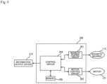
FIG. 5 is a block diagram of the controller shown inFIG. 1 ; and -
FIG. 6 is a diagram illustrating a master circuit and a slave circuit in a controller. - Referring to the drawings, a
turbomolecular pump 100 of an embodiment of a vacuum pump according to the present invention is now described. First, referring toFIGS. 1 to 4 , the overall configuration of theturbomolecular pump 100 is described. -
FIG. 1 is a vertical cross-sectional view of theturbomolecular pump 100. As shown inFIG. 1 , theturbomolecular pump 100 has a circularouter cylinder 127 having aninlet port 101 at its upper end. A rotatingbody 103 in theouter cylinder 127 includes a plurality of rotor blades 102 (102a, 102b, 102c, ...), which are turbine blades for gas suction and exhaustion, in its outer circumference section. The rotor blades 102 extend radially in multiple stages. The rotatingbody 103 has arotor shaft 113 in its center. Therotor shaft 113 is supported and suspended in the air and position-controlled by a magnetic bearing 115 (FIG. 5 ) of 5-axis control, for example. Themagnetic bearing 115 includeselectromagnets FIG. 1 . The rotatingbody 103 is typically made of a metal such as aluminum or an aluminum alloy. - Upper
radial electromagnets 104 include four electromagnets arranged in pairs on an X-axis and a Y-axis. Four upperradial sensors 107 are provided in close proximity to the upperradial electromagnets 104 and associated with the respective upperradial electromagnets 104. Each upperradial sensor 107 may be an inductance sensor or an eddy current sensor having a conduction winding, for example, and detects the position of therotor shaft 113 based on a change in the inductance of the conduction winding, which changes according to the position of therotor shaft 113. The upperradial sensors 107 are configured to detect a radial displacement of therotor shaft 113, that is, therotating body 103 fixed to therotor shaft 113, and send it to thecontroller 200. The controller (control means) 200 of the present embodiment includes a magneticbearing control circuit 201 and amotor control circuit 202 shown inFIG. 5 . - In the magnetic
bearing control circuit 201, for example, a compensation circuit having a PID adjustment function generates an excitation control command signal for the upperradial electromagnets 104 based on a position signal detected by the upperradial sensors 107. Based on this excitation control command signal, an amplifier circuit 150 (described below) shown inFIG. 2 controls and excites the upperradial electromagnets 104 to adjust the radial position of the upper part of therotor shaft 113. - The
rotor shaft 113 may be made of a high magnetic permeability material (such as iron and stainless steel) and is configured to be attracted by magnetic forces of the upperradial electromagnets 104. The adjustment is performed independently in the X-axis direction and the Y-axis direction. Lowerradial electromagnets 105 and lowerradial sensors 108 are arranged in a similar manner as the upperradial electromagnets 104 and the upperradial sensors 107 to adjust the radial position of the lower part of therotor shaft 113 in a similar manner as the radial position of the upper part. - Additionally,
axial electromagnets metal disc 111, which has a shape of a circular disc and is provided in the lower part of therotor shaft 113. Themetal disc 111 is made of a high magnetic permeability material such as iron. Anaxial sensor 109 is provided to detect an axial displacement of therotor shaft 113 and send an axial position signal to the magneticbearing control circuit 201. - In the magnetic
bearing control circuit 201, the compensation circuit having the PID adjustment function may generate an excitation control command signal for each of theaxial electromagnets axial sensor 109. Based on these excitation control command signals, theamplifier circuit 150 controls and excites theaxial electromagnets axial electromagnet 106A magnetically attracts themetal disc 111 upward and theaxial electromagnet 106B attracts themetal disc 111 downward. The axial position of therotor shaft 113 is thus adjusted. - As described above, the magnetic
bearing control circuit 201 appropriately adjusts the magnetic forces exerted by theaxial electromagnets metal disc 111, magnetically levitates therotor shaft 113 in the axial direction, and suspends therotor shaft 113 in the air in a non-contact manner. Theamplifier circuit 150, which controls and excites the upperradial electromagnets 104, the lowerradial electromagnets 105, and theaxial electromagnets - The
motor 121 includes a plurality of magnetic poles circumferentially arranged to surround therotor shaft 113. Each magnetic pole is controlled by themotor control circuit 202 so as to drive and rotate therotor shaft 113 via an electromagnetic force acting between the magnetic pole and therotor shaft 113. Themotor 121 also includes a rotational speed sensor (not shown), such as a Hall element, a resolver, or an encoder, and the rotational speed of therotor shaft 113 is detected based on a detection signal of the rotational speed sensor. - Furthermore, a phase sensor (not shown) is attached adjacent to the lower
radial sensors 108 to detect the phase of rotation of therotor shaft 113. Themotor control circuit 200 detects the position of the magnetic poles using both detection signals of the phase sensor and the rotational speed sensor. - A plurality of stator blades 123 (123a, 123b, 123c, ...) are arranged slightly spaced apart from the rotor blades 102 (102a, 102b, 102c, ...). Each rotor blade 102 (102a, 102b, 102c, ...) is inclined by a predetermined angle from a plane perpendicular to the axis of the
rotor shaft 113 in order to transfer exhaust gas molecules downward through collision. The stator blades 123 (123a, 123b, 123c, ...) are made of a metal such as aluminum, iron, stainless steel, copper, or a metal such as an alloy containing these metals as components. - The stator blades 123 are also inclined by a predetermined angle from a plane perpendicular to the axis of the
rotor shaft 113. The stator blades 123 extend inward of theouter cylinder 127 and alternate with the stages of the rotor blades 102. The outer circumference ends of the stator blades 123 are inserted between and thus supported by a plurality of layered stator blade spacers 125 (125a, 125b, 125c, ...). - The stator blade spacers 125 are ring-shaped members made of a metal, such as aluminum, iron, stainless steel, or copper, or an alloy containing these metals as components, for example. The
outer cylinder 127 is fixed to the outer circumferences of the stator blade spacers 125 with a slight gap. Abase portion 129 is located at the base of theouter cylinder 127. Thebase portion 129 has anoutlet port 133 providing communication to the outside. The exhaust gas transferred to thebase portion 129 through theinlet port 101 from the chamber (vacuum chamber) side is then sent to theoutlet port 133. - According to the application of the
turbomolecular pump 100, a threadedspacer 131 may be provided between the lower part of the stator blade spacer 125 and thebase portion 129. The threadedspacer 131 is a cylindrical member made of a metal such as aluminum, copper, stainless steel, or iron, or an alloy containing these metals as components. The threadedspacer 131 has a plurality ofhelical thread grooves 131a in its inner circumference surface. When exhaust gas molecules move in the rotation direction of therotating body 103, these molecules are transferred toward theoutlet port 133 in the direction of the helix of thethread grooves 131a. In the lowermost section of therotating body 103 below the rotor blades 102 (102a, 102b, 102c, ...), acylindrical portion 102d extends downward. The outer circumference surface of thecylindrical portion 102d is cylindrical and projects toward the inner circumference surface of the threadedspacer 131. The outer circumference surface is adjacent to but separated from the inner circumference surface of the threadedspacer 131 by a predetermined gap. The exhaust gas transferred to thethread grooves 131a by the rotor blades 102 and the stator blades 123 is guided by thethread grooves 131a to thebase portion 129. - The
base portion 129 is a disc-shaped member forming the base section of theturbomolecular pump 100, and is generally made of a metal such as iron, aluminum, or stainless steel. Thebase portion 129 physically holds theturbomolecular pump 100 and also serves as a heat conduction path. As such, thebase portion 129 is preferably made of rigid metal with high thermal conductivity, such as iron, aluminum, or copper. - In this configuration, when the
motor 121 drives and rotates the rotor blades 102 together with therotor shaft 113, the interaction between the rotor blades 102 and the stator blades 123 causes the suction of exhaust gas from the chamber through theinlet port 101. The rotational speed of the rotor blades 102 is usually 20000 rpm to 90000 rpm, and the circumferential speed at the tip of a rotor blade 102 reaches 200 m/s to 400 m/s. The exhaust gas taken through theinlet port 101 moves between the rotor blades 102 and the stator blades 123 and is transferred to thebase portion 129. At this time, factors such as the friction heat generated when the exhaust gas comes into contact with the rotor blades 102 and the conduction of heat generated by themotor 121 increase the temperature of the rotor blades 102. This heat is conducted to the stator blades 123 through radiation or conduction via gas molecules of the exhaust gas, for example. - The stator blade spacers 125 are joined to each other at the outer circumference portion and conduct the heat received by the stator blades 123 from the rotor blades 102, the friction heat generated when the exhaust gas comes into contact with the stator blades 123, and the like to a main
body casing portion 114. - In the above description, the threaded
spacer 131 is provided at the outer circumference of thecylindrical portion 102d of therotating body 103, and thethread grooves 131a are engraved in the inner circumference surface of the threadedspacer 131. However, this may be inversed in some cases, and a thread groove may be engraved in the outer circumference surface of thecylindrical portion 102d, while a spacer having a cylindrical inner circumference surface may be arranged around the outer circumference surface. - According to the application of the
turbomolecular pump 100, to prevent the gas drawn through theinlet port 101 from entering an electrical portion, which includes the upperradial electromagnets 104, the upperradial sensors 107, themotor 121, the lowerradial electromagnets 105, the lowerradial sensors 108, theaxial electromagnets axial sensor 109, the electrical portion may be surrounded by astator column 122. The inside of thestator column 122 may be maintained at a predetermined pressure by purge gas. - In this case, the
base portion 129 has a pipe (not shown) through which the purge gas is introduced. The introduced purge gas is sent to theoutlet port 133 through gaps between aprotective bearing 120 and therotor shaft 113, between the rotor and the stator of themotor 121, and between thestator column 122 and the inner circumference cylindrical portion of the rotor blade 102. - The
turbomolecular pump 100 requires the identification of the model and control based on individually adjusted unique parameters (for example, various characteristics associated with the model). To store these control parameters, theturbomolecular pump 100 includes anelectronic circuit portion 141 in its main body. Theelectronic circuit portion 141 may include a semiconductor memory, such as an EEPROM, electronic components such as semiconductor elements for accessing the semiconductor memory, and asubstrate 143 for mounting these components. Theelectronic circuit portion 141 is housed under a rotational speed sensor (not shown) near the center, for example, of thebase portion 129, which forms the lower part of theturbomolecular pump 100, and is closed by anairtight bottom lid 145. - Some process gas introduced into the chamber in the manufacturing process of semiconductors has the property of becoming solid when its pressure becomes higher than a predetermined value or its temperature becomes lower than a predetermined value. In the
turbomolecular pump 100, the pressure of the exhaust gas is lowest at theinlet port 101 and highest at theoutlet port 133. When the pressure of the process gas increases beyond a predetermined value or its temperature decreases below a predetermined value while the process gas is being transferred from theinlet port 101 to theoutlet port 133, the process gas is solidified and adheres and accumulates on the inner side of theturbomolecular pump 100. - For example, when SiCl4 is used as the process gas in an Al etching apparatus, according to the vapor pressure curve, a solid product (for example, AlCl3) is deposited at a low vacuum (760 [torr] to 10-2 [torr]) and a low temperature (about 20 [°C]) and adheres and accumulates on the inner side of the
turbomolecular pump 100. When the deposit of the process gas accumulates in theturbomolecular pump 100, the accumulation may narrow the pump flow passage and degrade the performance of theturbomolecular pump 100. The above-mentioned product tends to solidify and adhere in areas with higher pressures, such as the vicinity of the outlet port and the vicinity of the threadedspacer 131. - To solve this problem, conventionally, an annular water-cooled
tube 149 is wound around the outer circumference of the main body casing portion or thebase portion 129, and a temperature sensor (e.g., a thermistor, not shown) is embedded in thebase portion 129, for example. The signal of this temperature sensor is used to perform control to maintain the temperature of thebase portion 129 at a constant high temperature (preset temperature) by heating with the heater or cooling with the water-cooled tube 149 (hereinafter referred to as TMS (temperature management system)). - The
amplifier circuit 150 is now described that controls and excites the upperradial electromagnets 104, the lowerradial electromagnets 105, and theaxial electromagnets turbomolecular pump 100 configured as described above.FIG. 2 is a circuit diagram of theamplifier circuit 150. - In
FIG. 2 , one end of an electromagnet winding 151 forming an upperradial electromagnet 104 or the like is connected to a positive electrode 171a of apower supply 171 via atransistor 161, and the other end is connected to anegative electrode 171b of thepower supply 171 via acurrent detection circuit 181 and atransistor 162. Eachtransistor - In the
transistor 161, acathode terminal 161a of its diode is connected to the positive electrode 171a, and ananode terminal 161b is connected to one end of the electromagnet winding 151. In thetransistor 162, acathode terminal 162a of its diode is connected to acurrent detection circuit 181, and an anode terminal 162b is connected to thenegative electrode 171b. - A diode 165 for current regeneration has a
cathode terminal 165a connected to one end of the electromagnet winding 151 and an anode terminal 165b connected to thenegative electrode 171b. Similarly, adiode 166 for current regeneration has acathode terminal 166a connected to the positive electrode 171a and an anode terminal 166b connected to the other end of the electromagnet winding 151 via thecurrent detection circuit 181. Thecurrent detection circuit 181 may include a Hall current sensor or an electric resistance element, for example. - The
amplifier circuit 150 configured as described above corresponds to one electromagnet. Accordingly, when the magnetic bearing uses 5-axis control and has tenelectromagnets identical amplifier circuit 150 is configured for each of the electromagnets. These tenamplifier circuits 150 are connected to thepower supply 171 in parallel. - An
amplifier control circuit 191 may be formed by a digital signal processor portion (not shown, hereinafter referred to as a DSP portion) of thecontroller 200. Theamplifier control circuit 191 switches thetransistors - The
amplifier control circuit 191 is configured to compare a current value detected by the current detection circuit 181 (a signal reflecting this current value is referred to as acurrent detection signal 191c) with a predetermined current command value. The result of this comparison is used to determine the magnitude of the pulse width (pulse width time Tp1, Tp2) generated in a control cycle Ts, which is one cycle in PWM control. As a result, gate drive signals 191a and 191b having this pulse width are output from theamplifier control circuit 191 to gate terminals of thetransistors - Under certain circumstances such as when the rotational speed of the
rotating body 103 reaches a resonance point during acceleration, or when a disturbance occurs during a constant speed operation, therotating body 103 may require positional control at high speed and with a strong force. For this purpose, a high voltage of about 50 V, for example, is used for thepower supply 171 to enable a rapid increase (or decrease) in the current flowing through the electromagnet winding 151. Additionally, a capacitor is generally connected between the positive electrode 171a and thenegative electrode 171b of thepower supply 171 to stabilize the power supply 171 (not shown). - In this configuration, when both
transistors - Also, when one of the
transistors amplifier circuit 150 in this manner reduces the hysteresis loss in theamplifier circuit 150, thereby limiting the power consumption of the entire circuit to a low level. Moreover, by controlling thetransistors turbomolecular pump 100 can be reduced. Furthermore, by measuring this freewheeling current with thecurrent detection circuit 181, the electromagnet current iL flowing through the electromagnet winding 151 can be detected. - That is, when the detected current value is smaller than the current command value, as shown in
FIG. 3 , thetransistors negative electrode 171b via thetransistors - When the detected current value is larger than the current command value, as shown in
FIG. 4 , thetransistors negative electrode 171b to the positive electrode 171a via thediodes 165 and 166. - In either case, after the pulse width time Tp1, Tp2 has elapsed, one of the
transistors amplifier circuit 150. - Referring to
FIG. 5 , the controller 200 (control means) of the present embodiment is now described in detail. Thecontroller 200 of the present embodiment includes the magneticbearing control circuit 201, themotor control circuit 202, thecontrol circuit 204, and amemory 205. - The magnetic
bearing control circuit 201 is connected to thesensors electromagnets magnetic bearing 115 based on the position information of therotor shaft 113 detected by thesensors - The
motor control circuit 202 is connected to the above-mentioned motor 121 (incorporating a rotational speed sensor (not shown)) and a phase sensor (not shown) and controls the operation of themotor 121 based on the rotational speed and the phase of therotor shaft 113 detected by the rotational speed sensor and the phase sensor. - The
control circuit 204 is connected to the magneticbearing control circuit 201 and themotor control circuit 202. Thecontrol circuit 204 periodically communicates with the magneticbearing control circuit 201 and with themotor control circuit 202, and thus controls the operation of themagnetic bearing 115, which is connected to the magneticbearing control circuit 201, and the operation of themotor 121, which is connected to themotor control circuit 202. That is, thecontrol circuit 204 corresponds to a "master circuit" in a master-slave system, and the magneticbearing control circuit 201 and themotor control circuit 202 correspond to "slave circuits" in the master-slave control. In one example, the interval of communications performed by thecontrol circuit 204 with the magneticbearing control circuit 201 and themotor control circuit 202 is 30 ms to 100 ms. - The
control circuit 204 is also connected to thememory 205. Thememory 205 may be a FeRAM, for example. Thememory 205 may be a non-volatile memory (for example, EEPROM) other than FeRAM, or a volatile memory (SRAM or DRAM). Thecontrol circuit 204 also has the function of storing a "history of communication states" described below in thememory 205 and calling it from thememory 205. - The
control circuit 204 is also connected to aninformation output device 210. For example, theinformation output device 210 may be an LCD attached to theturbomolecular pump 100, and displays various types of information about theturbomolecular pump 100 in texts, images, and the like so that the user can perceive it. Theinformation output device 210 may be a component that emits light (blinks), such as an LED. Also, theinformation output device 210 is not limited to a component that allows the user to visually perceive the information, such as an LCD and an LED, and may be a component that allows for perception through another sense (for example, sound may be output and perceived by the user's sense of hearing). - The
control circuit 204 of the present embodiment has the function of obtaining the history of states of communications with the magneticbearing control circuit 201 and themotor control circuit 202, which are slave circuits. - Referring to
FIG. 6 , the "history of communication states" is now described in detail. When thecontrol circuit 204, which is the master circuit, transmits data including request content to the magnetic bearing control circuit 201 (or the motor control circuit 202), which is a slave circuit, the magnetic bearing control circuit 201 (or the motor control circuit 202) transmits data including response content to thecontrol circuit 204. Thecontrol circuit 204 of the present embodiment has the function of counting the number of communications performed between the master circuit and the slave circuits, and can calculate the total number of communications between the master circuit and the slave circuits. In an example of a method for counting the number of communications, the cumulative number is stored in thememory 205, and thecontrol circuit 204 counts up this cumulative number in thememory 205 each time the master circuit communicates with a slave circuit. This total number of communications is included in the "history of communication states". - The "history of communication states" also includes the history of communication errors that occur between the master circuit and the slave circuits. The types of "communication error" include an error that occurs when the communication element of the master circuit is abnormal and data cannot be sent to the slave circuit, an error that occurs when the master circuit sends data and then fails to receive data from the slave circuit, an error that occurs when data from the slave circuit cannot be used, and an error that occurs when data from the slave circuit is usable but not expected data (for example, the numerical value in the data is not in the specified range). Regarding the communication errors described above, the
control circuit 204 of the present embodiment has the function of counting the number of communication errors of each type in a predetermined period and counting the total number of all communication errors in a predetermined period. Thecontrol circuit 204 also has the function of calculating the occurrence ratio of communication errors in a predetermined period (for example, the ratio obtained by dividing the number of communication errors of each type by the total number of communications between the master circuit and the slave circuits, and the ratio obtained by dividing the total number of communication errors by the total number of communications between the master circuit and the slave circuits). The "predetermined period" is not limited to the period from the time of the initial startup of theturbomolecular pump 100 to the current time, and may be a specific period. That is, in counting the number of communication errors and the like, the number of communication errors from the initial startup of theturbomolecular pump 100 may be counted, or the number of communication errors after a periodical inspection of theturbomolecular pump 100 may be counted. - The
control circuit 204 also has the function of detecting a plurality of communication errors occurring in succession. - The "history of communication states" includes, regarding the most recent communication error, at least one of data including the request content sent by the master circuit to the slave circuit, data including the response content sent by the slave circuit to the master circuit, the type of the communication error, or the time at which the communication error occurred. As described above, the
memory 205 stores the "history of communication states". Storing the error occurrence times or the like for all communication errors would result in an enormous volume of data stored in thememory 205. For this reason, the present embodiment stores the error occurrence time or the like only for the most recent communication error (the previously stored data is deleted from the memory 205). This minimizes the volume of data to be stored in thememory 205. - As for the "history of communication states" described above, the
control circuit 204 also has the function of issuing an alarm to the outside based on the "history of communication states". In the present embodiment, thecontrol circuit 204 is configured to cause theinformation output device 210 to issue an alarm (for example, causes an LCD to display that theturbomolecular pump 100 has an abnormality) when the total number of communication errors in a predetermined period exceeds a predetermined number. The information representing the above "predetermined number" is stored in thememory 205 or a storage portion (not shown) as a threshold value. Thecontrol circuit 204 sends a signal to theinformation output device 210 when the total number of communication errors exceeds the threshold value stored in thememory 205 or the like to cause theinformation output device 210 to issue an alarm. This allows the user to perceive that theturbomolecular pump 100 has an abnormality. - The signal sent from the
control circuit 204 to cause theinformation output device 210 to issue an alarm does not have to be based on the total number of communication errors in a predetermined period. An alarm may be issued based on the occurrence ratio of communication errors in a predetermined period, or in response to a plurality of communication errors occurring in succession. - As described above, the
memory 205 stores the "history of communication states". That is, even when sudden external noise causes a communication error, for example, the cause of the communication error can be identified by analyzing the data on the "history of communication states" stored in thememory 205, allowing effective measures to be taken against external noise. Also, in the stage of developing a new type ofturbomolecular pump 100 with such a function, the communication quality can be evaluated by identifying the noise immunities in the communications between the master circuit and the slave circuits through various tests. Thus, measures to increase the noise resistance can be taken from the development stage. In the stage of mass production ofturbomolecular pumps 100, variations in noise immunity due to the variations among devices can be identified in the manufacturing process and used as one of the quality evaluation items for the turbomolecular pumps 100 to be mass-produced. - The present invention is not limited to the embodiments described above. Various modifications, alternations, and combinations are possible within the scope of the invention described in the claims unless otherwise specified in the above description. Also, the effects of the embodiment described above are merely examples of the effects of the present invention. The effects of the present invention are not limited to the effects described above.
- For example, the slave circuits in the present embodiment are the magnetic
bearing control circuit 201 and themotor control circuit 202, but any circuit that controls the operation of a portion of the vacuum pump may serve as a slave circuit according to the present invention. Examples of such a slave circuit include an Ethernet circuit that can output information of theturbomolecular pump 100 to an external device and input information from the external device to theturbomolecular pump 100. -
- 100
- Turbomolecular pump (vacuum pump)
- 201
- Magnetic bearing control circuit (slave circuit)
- 202
- Motor control circuit (slave circuit)
- 204
- Control circuit (master circuit)
Claims (8)
- A vacuum pump comprising:a control means configured to control an operation of each of portions included in the vacuum pump, whereinthe control means includes a slave circuit connected to each of the portions to control the operation of each of the portions and a master circuit connected to the slave circuit to control the slave circuit, andthe master circuit is configured to perform periodical communications with the slave circuit and obtain a history of communication states of the communications.
- The vacuum pump according to claim 1, configured to issue an alarm to an outside based on the history of communication states.
- The vacuum pump according to claim 2, wherein the alarm is issued based on a total number of communication errors in a predetermined period.
- The vacuum pump according to claim 2, wherein the alarm is issued, based on an occurrence ratio of communication errors in a predetermined period.
- The vacuum pump according to claim 2, wherein the alarm is issued in response to a plurality of communication errors occurring in succession.
- The vacuum pump according to claim 1, wherein the history of communication states includes at least one of request content of data, response content of data, an error type, or a time of a most recent communication error.
- The vacuum pump according to claim 1, wherein the history of communication states includes a number of communication errors of each type.
- A controller for controlling an operation of each of portions included in a vacuum pump, the controller comprising:a slave circuit connected to each of the portions to control the operation of each of the portions; anda master circuit connected to the slave circuit to control the slave circuit, whereinthe master circuit is configured to perform periodical communications with the slave circuit and obtain a history of communication states of the communications.
Applications Claiming Priority (2)
| Application Number | Priority Date | Filing Date | Title |
|---|---|---|---|
| JP2021192231A JP7595554B2 (en) | 2021-11-26 | 2021-11-26 | Vacuum pump and control device |
| PCT/JP2022/043432 WO2023095851A1 (en) | 2021-11-26 | 2022-11-24 | Vacuum pump and control device |
Publications (2)
| Publication Number | Publication Date |
|---|---|
| EP4438904A1 true EP4438904A1 (en) | 2024-10-02 |
| EP4438904A4 EP4438904A4 (en) | 2025-11-19 |
Family
ID=86539534
Family Applications (1)
| Application Number | Title | Priority Date | Filing Date |
|---|---|---|---|
| EP22898633.7A Pending EP4438904A4 (en) | 2021-11-26 | 2022-11-24 | VACUUM PUMP AND CONTROL DEVICE |
Country Status (7)
| Country | Link |
|---|---|
| US (1) | US12359673B2 (en) |
| EP (1) | EP4438904A4 (en) |
| JP (1) | JP7595554B2 (en) |
| KR (1) | KR20240113454A (en) |
| CN (1) | CN118140052A (en) |
| IL (1) | IL312161A (en) |
| WO (1) | WO2023095851A1 (en) |
Family Cites Families (10)
| Publication number | Priority date | Publication date | Assignee | Title |
|---|---|---|---|---|
| JP3179441B2 (en) * | 1999-03-30 | 2001-06-25 | セイコー精機株式会社 | Communication abnormality detection and / or countermeasure device and vacuum pump remote monitoring and control device |
| US6961363B1 (en) * | 1999-12-02 | 2005-11-01 | International Business Machines Corporation | Frequency look-ahead and link state history based scheduling in indoor wireless pico-cellular networks |
| JP2002295398A (en) * | 2001-03-28 | 2002-10-09 | Boc Edwards Technologies Ltd | Device and method for protecting turbo molecular pump |
| US20030175112A1 (en) * | 2002-03-13 | 2003-09-18 | Hirotaka Namiki | Vacuum pump system and vacuum pump RPM control method |
| US20090287789A1 (en) * | 2008-05-16 | 2009-11-19 | Square D Company | Web browser accessible MODBUS TCP/IP activity log |
| CN101683849B (en) * | 2008-09-28 | 2012-05-30 | 比亚迪股份有限公司 | Brake vacuum boosting system and brake vacuum boosting control method |
| JP2012004759A (en) * | 2010-06-16 | 2012-01-05 | Mitsubishi Electric Corp | Radio communication device |
| JP6551259B2 (en) * | 2016-02-26 | 2019-07-31 | オムロン株式会社 | Master device, slave device, error monitoring system, master device control method, and control program |
| JP2019022106A (en) * | 2017-07-19 | 2019-02-07 | アズビル株式会社 | Communications system |
| JP7377660B2 (en) | 2019-09-27 | 2023-11-10 | エドワーズ株式会社 | Vacuum pump and vacuum pump accessory unit |
-
2021
- 2021-11-26 JP JP2021192231A patent/JP7595554B2/en active Active
-
2022
- 2022-11-24 WO PCT/JP2022/043432 patent/WO2023095851A1/en not_active Ceased
- 2022-11-24 IL IL312161A patent/IL312161A/en unknown
- 2022-11-24 EP EP22898633.7A patent/EP4438904A4/en active Pending
- 2022-11-24 CN CN202280070700.0A patent/CN118140052A/en active Pending
- 2022-11-24 KR KR1020247010488A patent/KR20240113454A/en active Pending
- 2022-11-24 US US18/702,673 patent/US12359673B2/en active Active
Also Published As
| Publication number | Publication date |
|---|---|
| JP2023078905A (en) | 2023-06-07 |
| US20240410381A1 (en) | 2024-12-12 |
| TW202332834A (en) | 2023-08-16 |
| IL312161A (en) | 2024-06-01 |
| US12359673B2 (en) | 2025-07-15 |
| JP7595554B2 (en) | 2024-12-06 |
| CN118140052A (en) | 2024-06-04 |
| KR20240113454A (en) | 2024-07-22 |
| WO2023095851A1 (en) | 2023-06-01 |
| EP4438904A4 (en) | 2025-11-19 |
Similar Documents
| Publication | Publication Date | Title |
|---|---|---|
| EP4166790A1 (en) | Vacuum pump | |
| EP4325060A1 (en) | Turbo-molecular pump | |
| EP4212729A1 (en) | Vacuum pump | |
| EP4163498A1 (en) | Vacuum pump and vacuum pump rotating body | |
| EP4303446A1 (en) | Vacuum pump | |
| EP4450819A1 (en) | Vacuum pump and control device | |
| US12152605B2 (en) | Vacuum pump and controller | |
| EP4357618A1 (en) | Vacuum pump | |
| WO2020158658A1 (en) | Vacuum pump and vacuum pump control device | |
| US12234828B2 (en) | Vacuum pump and vacuum pump rotor blade | |
| US12359673B2 (en) | Vacuum pump and control device | |
| EP4202227A1 (en) | Vacuum pump, fixed blade, and spacer | |
| KR20230116781A (en) | vacuum pump | |
| JP2022094272A (en) | Vacuum pump | |
| JP7691450B2 (en) | Vacuum pump and vacuum pump control device | |
| US12188477B2 (en) | Vacuum pump and rotating cylinder provided in vacuum pump | |
| JP7762691B2 (en) | Vacuum pump abnormality detection device, vacuum pump system, and vacuum pump abnormality detection method | |
| EP4737734A1 (en) | Vacuum pump and hermetic connector | |
| WO2024203989A1 (en) | Vacuum pump, magnetic bearing control device, and compression/decompression method | |
| EP4227537A1 (en) | Vacuum pump and vacuum exhaust system which uses same | |
| TW202449295A (en) | Vacuum pump and operating method for vacuum pump |
Legal Events
| Date | Code | Title | Description |
|---|---|---|---|
| STAA | Information on the status of an ep patent application or granted ep patent |
Free format text: STATUS: THE INTERNATIONAL PUBLICATION HAS BEEN MADE |
|
| PUAI | Public reference made under article 153(3) epc to a published international application that has entered the european phase |
Free format text: ORIGINAL CODE: 0009012 |
|
| STAA | Information on the status of an ep patent application or granted ep patent |
Free format text: STATUS: REQUEST FOR EXAMINATION WAS MADE |
|
| 17P | Request for examination filed |
Effective date: 20240416 |
|
| AK | Designated contracting states |
Kind code of ref document: A1 Designated state(s): AL AT BE BG CH CY CZ DE DK EE ES FI FR GB GR HR HU IE IS IT LI LT LU LV MC ME MK MT NL NO PL PT RO RS SE SI SK SM TR |
|
| DAV | Request for validation of the european patent (deleted) | ||
| DAX | Request for extension of the european patent (deleted) | ||
| A4 | Supplementary search report drawn up and despatched |
Effective date: 20251020 |
|
| RIC1 | Information provided on ipc code assigned before grant |
Ipc: F04D 19/04 20060101AFI20251014BHEP Ipc: F04D 27/00 20060101ALI20251014BHEP Ipc: F04D 27/02 20060101ALI20251014BHEP |