EP4438885A1 - Purge valve control method and control device of evaporated fuel processing device - Google Patents
Purge valve control method and control device of evaporated fuel processing device Download PDFInfo
- Publication number
- EP4438885A1 EP4438885A1 EP21964983.7A EP21964983A EP4438885A1 EP 4438885 A1 EP4438885 A1 EP 4438885A1 EP 21964983 A EP21964983 A EP 21964983A EP 4438885 A1 EP4438885 A1 EP 4438885A1
- Authority
- EP
- European Patent Office
- Prior art keywords
- purge valve
- purge
- time period
- opening time
- intake
- Prior art date
- Legal status (The legal status is an assumption and is not a legal conclusion. Google has not performed a legal analysis and makes no representation as to the accuracy of the status listed.)
- Withdrawn
Links
Images


Classifications
-
- F—MECHANICAL ENGINEERING; LIGHTING; HEATING; WEAPONS; BLASTING
- F02—COMBUSTION ENGINES; HOT-GAS OR COMBUSTION-PRODUCT ENGINE PLANTS
- F02M—SUPPLYING COMBUSTION ENGINES IN GENERAL WITH COMBUSTIBLE MIXTURES OR CONSTITUENTS THEREOF
- F02M25/00—Engine-pertinent apparatus for adding non-fuel substances or small quantities of secondary fuel to combustion-air, main fuel or fuel-air mixture
- F02M25/08—Engine-pertinent apparatus for adding non-fuel substances or small quantities of secondary fuel to combustion-air, main fuel or fuel-air mixture adding fuel vapours drawn from engine fuel reservoir
-
- F—MECHANICAL ENGINEERING; LIGHTING; HEATING; WEAPONS; BLASTING
- F02—COMBUSTION ENGINES; HOT-GAS OR COMBUSTION-PRODUCT ENGINE PLANTS
- F02D—CONTROLLING COMBUSTION ENGINES
- F02D41/00—Electrical control of supply of combustible mixture or its constituents
- F02D41/0025—Controlling engines characterised by use of non-liquid fuels, pluralities of fuels, or non-fuel substances added to the combustible mixtures
- F02D41/003—Adding fuel vapours, e.g. drawn from engine fuel reservoir
- F02D41/0032—Controlling the purging of the canister as a function of the engine operating conditions
- F02D41/004—Control of the valve or purge actuator, e.g. duty cycle, closed loop control of position
-
- F—MECHANICAL ENGINEERING; LIGHTING; HEATING; WEAPONS; BLASTING
- F02—COMBUSTION ENGINES; HOT-GAS OR COMBUSTION-PRODUCT ENGINE PLANTS
- F02D—CONTROLLING COMBUSTION ENGINES
- F02D41/00—Electrical control of supply of combustible mixture or its constituents
- F02D41/009—Electrical control of supply of combustible mixture or its constituents using means for generating position or synchronisation signals
-
- F—MECHANICAL ENGINEERING; LIGHTING; HEATING; WEAPONS; BLASTING
- F02—COMBUSTION ENGINES; HOT-GAS OR COMBUSTION-PRODUCT ENGINE PLANTS
- F02D—CONTROLLING COMBUSTION ENGINES
- F02D41/00—Electrical control of supply of combustible mixture or its constituents
- F02D41/02—Circuit arrangements for generating control signals
- F02D41/04—Introducing corrections for particular operating conditions
- F02D41/047—Taking into account fuel evaporation or wall wetting
-
- F—MECHANICAL ENGINEERING; LIGHTING; HEATING; WEAPONS; BLASTING
- F02—COMBUSTION ENGINES; HOT-GAS OR COMBUSTION-PRODUCT ENGINE PLANTS
- F02M—SUPPLYING COMBUSTION ENGINES IN GENERAL WITH COMBUSTIBLE MIXTURES OR CONSTITUENTS THEREOF
- F02M25/00—Engine-pertinent apparatus for adding non-fuel substances or small quantities of secondary fuel to combustion-air, main fuel or fuel-air mixture
- F02M25/08—Engine-pertinent apparatus for adding non-fuel substances or small quantities of secondary fuel to combustion-air, main fuel or fuel-air mixture adding fuel vapours drawn from engine fuel reservoir
- F02M25/0836—Arrangement of valves controlling the admission of fuel vapour to an engine, e.g. valve being disposed between fuel tank or absorption canister and intake manifold
-
- F—MECHANICAL ENGINEERING; LIGHTING; HEATING; WEAPONS; BLASTING
- F02—COMBUSTION ENGINES; HOT-GAS OR COMBUSTION-PRODUCT ENGINE PLANTS
- F02M—SUPPLYING COMBUSTION ENGINES IN GENERAL WITH COMBUSTIBLE MIXTURES OR CONSTITUENTS THEREOF
- F02M25/00—Engine-pertinent apparatus for adding non-fuel substances or small quantities of secondary fuel to combustion-air, main fuel or fuel-air mixture
- F02M25/08—Engine-pertinent apparatus for adding non-fuel substances or small quantities of secondary fuel to combustion-air, main fuel or fuel-air mixture adding fuel vapours drawn from engine fuel reservoir
- F02M25/089—Layout of the fuel vapour installation
Definitions
- the present invention relates to an evaporative fuel processing device employing a canister, and particularly to control of a purge valve provided in a purge passage between the canister and an intake passage of an internal combustion engine.
- an evaporative fuel processing device is commonly used in order to prevent evaporative fuel, which occurs in a vehicle fuel tank, from leaking outside.
- the evaporative fuel processing device is configured to temporarily adsorb evaporative fuel in a canister employing an adsorbent such as activated carbon, and thereafter, while an internal combustion engine is operating, purge a fuel component from the canister by introduction of fresh air, and introduce the fuel component into an intake system of the internal combustion engine.
- the purge valve provided in the purge passage is duty-controlled at a suitable driving frequency in order to control a flow rate of purge gas introduced into an intake passage of the internal combustion engine.
- a quantity of purge gas is measured based on a pressure difference across a purge valve in a purge passage, and a time period in which the purge valve is opened (namely, duty ratio).
- a time period in which the purge valve is opened namely, duty ratio.
- an intake pulsation occurs which has a cycle time depending on a number of cylinders. The intake pulsation has a relatively small influence, when an average pressure in the intake passage is sufficiently low and the pressure difference across the purge valve is large, such as when an internal combustion engine is undergoing a relatively low load.
- Patent Documents 1 and 2 disclose techniques in which a plurality of purge valves are arranged in parallel with each other and time periods in which the purge valves are opened are shifted to have phases different from each other in order to shorten a cycle time of opening and closing as a whole. However, these documents are silent about the problem of the influence of intake pulsation and means for solving the problem.
- a purge valve control method for an evaporative fuel processing device wherein the evaporative combustion processing device includes at least one purge valve disposed in a purge passage between a canister and an intake passage of an internal combustion engine and configured to be duty-controlled, the purge valve control method includes: synchronizing a cycle, in which the at least one purge valve is opened, with rotation of the internal combustion engine; and setting an interval at one half of an odd number times a quantity ( ⁇ REF), wherein the interval is from a start point of a first opening time period of the at least one purge valve to a start point of a second opening time period of the at least one purge valve, wherein the second opening time period follows the first opening time period, wherein the quantity ( ⁇ REF) is an intake stroke interval determined by a number of cylinders of the internal combustion engine.
- an intake pulsation occurs, which has a cycle time determined by the number of cylinders connected to the intake passage. Pressure in the intake passage increases and decreases repeatedly in relation to the intake stroke of each cylinder. For example, in a simplified waveform, two adjacent peaks of the intake pulsation have an interval equal to ⁇ REF. Since the interval from the start point of the first opening time period to the start point of the second opening time period following the first opening time period is set equal to an odd multiple of ⁇ REF/2, the second opening time period starts with a valley of the intake pulsation waveform, if the first opening time period starts with a peak of the intake pulsation waveform.
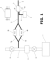
- FIG. 1 is an explanatory diagram schematically showing configuration of an evaporative fuel processing device in a vehicle equipped with an internal combustion engine 1.
- the evaporative fuel processing device serves to process evaporative fuel, which occurs in a fuel tank 2 of the vehicle while the vehicle is at rest or the like, while preventing the evaporative fuel from leaking outside.
- the evaporative fuel processing device is composed mainly of a canister 3 whose inside is filled with an adsorbent such as activated carbon for temporarily storing the evaporative fuel.
- the canister 3 includes an internal flow path which has a charge port 3a and a purge port 3b at its first end and a drain port 3c at its second end.
- the charge port 3a communicates with an upper space of the fuel tank 2 via a charge passage 4, whereas the purge port 3b communicates with an intake passage 7 of the internal combustion engine 1 via a purge passage 5. Furthermore, the drain port 3c is opened to the atmosphere via a drain passage 6.
- the drain passage 6 may be provided with a drain cut valve not shown for leakage inspection and the like.
- evaporative fuel occurs, and is introduced into the canister 3 through the charge passage 4, and is adsorbed by adsorbents in various parts while flowing through the adsorbents toward the drain port 3c.
- the thus adsorbed fuel component is purged from the adsorbents, and is introduced through the purge passage 5 into the intake system of the internal combustion engine 1, and is finally burnt in combustion chambers of the internal combustion engine 1 together with fuel supplied from fuel injection valves.
- the internal combustion engine 1 is a four-stroke cycle spark ignition engine, such as an in-line three-cylinder turbocharged engine. Accordingly, the intake passage 7 of the internal combustion engine 1 is provided with a compressor 11 of a turbocharger. A throttle valve 12 is disposed downstream of the compressor 11. Furthermore, an admission valve 13, which is composed of a butterfly valve or the like, is disposed in the intake passage 7 upstream of the compressor 11, for generating a negative pressure in the intake passage 7.
- the purge passage 5 has an end connected to the intake passage 7 between the admission valve 13 and the compressor 11.
- the purge passage 5 is provided with a pair of purge valves 8, wherein each purge valves 8 is composed of an electromagnetic valve for purge gas flow rate control.
- the purge passage 5 includes a section branched into a pair of purge passages 5a and 5b parallel with each other, wherein a first purge valve 8A is disposed in the purge passage 5a, and a second purge valve 8B is disposed in the purge passage 5b.
- the two purge valves 8A and 8B are arranged in parallel with each other. It is desirable that the pair of branched purge passages 5a and 5b have equal lengths.
- a section of the purge passage 5a between the purge valve 8A and the intake passage 7 is equal in length to a section of the purge passage 5b between the purge valve 8B and the intake passage 7.
- a length of passage from the end opening of the purge passage 5, which is connected to the intake passage 7, to the purge valve 8A is equal to a passage length from the end opening of the purge passage 5 to the purge valve 8B.
- the purge valves 8A and 8B are duty-controlled by a controller 9.
- the controller 9 is configured as a part of an engine controller that performs various controls of the internal combustion engine 1, wherein the controls include a fuel injection control, an ignition control, a control of opening of the throttle valve 12, a control of opening of the admission valve 13, etc.
- the duty control according to the present embodiment is performed such that the cycle time of opening of the purge valves 8A and 8B is synchronized with rotation (crank angle) of the internal combustion engine 1.
- the driving frequency of the duty control is set to vary in accordance with the rotational speed of the internal combustion engine 1, wherein drive pulse signals are outputted at predetermined crank angles.
- FIG. 2 is a time chart showing a relationship between (a) a waveform of intake pulsation in the intake passage 7 and (b) time periods in which the first and second purge valves 8A and 8B are opened.
- PCV1" and PCV2 represent the first and second purge valves 8A and 8B, respectively.
- #1", “#2", and “#3" are cylinder numbers. In this example, ignition is carried out in the order of "#1 -> #2 -> #3".
- the intake pulsation is caused by a process that each cylinder of the internal combustion engine 1 intermittently undergoes its intake stroke.
- the cycle time or frequency of the intake pulsation is determined by the number of cylinders sharing the intake passage 7.
- intake strokes occur every 240° CA (crank angle), causing an intake pulsation with a pressure waveform peaking every 240° CA, as shown in FIG. 2 (a) .
- an intake stroke interval ⁇ REF is equal to 240° CA.
- the crank angle of the internal combustion engine 1 is sensed by a so-called crank angle sensor or cam angle sensor not shown. Based on an output signal from the sensor, a REF signal is obtained every 240° CA (crank angle) as a reference for fuel injection timing control and ignition timing control of each cylinder.
- the intake stroke interval ⁇ REF is an interval from a REF signal for a certain cylinder (for example, cylinder #1) to a REF signal for the next cylinder (for example, cylinder #2) in the ignition order.
- broken lines each indicate the timing of the REF signal for each cylinder.
- the REF signal is outputted a certain crank angle before the compression top dead center of each cylinder.
- the intake stroke interval ⁇ REF may be handled in actual time instead of crank angle.
- Each of the first purge valve 8A and the second purge valve 8B is driven at intervals of an odd multiple of ⁇ REF.
- the cycle time of the drive pulse signal is equal to an odd multiple of ⁇ REF. More preferably, the odd number is equal to 2 ⁇ C+1, where C represents the number of cylinders.
- the cycle time of the drive pulse signal for each of the first purge valve 8A and the second purge valve 8B is equal to seven times ⁇ REF.
- the driving pulse signal for the first purge valve 8A and the driving pulse signal for the second purge valve 8B have rising edges that are different from each other by half the cycle time described above.
- the phase difference between each drive pulse signal of the duty control of the first purge valve 8A and each drive pulse signal of the duty control of the second purge valve 8B is equal to ( ⁇ REF ⁇ 7/2).
- the interval between the start point of one opening time period and the start point of the next opening time period is equal to ( ⁇ REF ⁇ 7/2).
- FIG. 2 (b) shows opening time periods of the first and second purge valves 8A and 8B based on the drive pulse signals.
- the duty ratio is relatively small.
- the first purge valve 8A and the second purge valve 8B are driven with equal duty ratios.
- the start point of the opening time period of the first purge valve 8A and the start point of the opening time period of the second purge valve 8B are shifted from each other by half the cycle time of each purge valve, wherein the cycle time is equal to an odd multiple of ⁇ REF.
- the first opening time period of the first purge valve 8A contains a section in which the intake pulsation waveform falls from a peak to a valley
- the following first opening time period of the second purge valve 8B includes a section in which the intake pulsation waveform rises from a valley to a peak. Therefore, the influence of intake pulsation on the purge gas flow rate is substantially canceled out by the first purge valve 8A and the second purge valve 8B, wherein the purge gas flow rate depends on the pressure difference across the purge valves 8A and 8B.
- the purge gas flow rate during the opening time period of the first purge valve 8A decreases
- the purge gas flow rate during the following opening time period of the second purge valve 8B increases.
- the purge gas flow rate during the opening time period of the second purge valve 8B decreases.
- the behavior of the intake pulsation with respect to REF varies somewhat depending on propagation velocity of pressure waves (sound velocity in the intake passage).
- the opening time periods of the two purge valves 8A and 8B in the in-line three-cylinder engine are set to have a phase difference of ( ⁇ REF ⁇ 7/2) from each other, taking into account the number of cylinders. Accordingly, as illustrated in FIG. 2 , if the first opening time period of the first purge valve 8A contains a section of descending from a peak corresponding to the cylinder #1 to a valley, the following opening time period of the second purge valve 8B contains a section of rising from a valley corresponding to the cylinder #1 to a next peak corresponding to the cylinder #2.
- the next opening time period of the first purge valve 8A contains a section of descending from a peak corresponding to the cylinder #2 to a valley
- the following opening time period of the second purge valve 8B contains a section of rising from a valley corresponding to the same cylinder #2 to a next peak corresponding to the cylinder #3.
- next opening time period of the first purge valve 8A contains a section of descending from a peak corresponding to the cylinder #3 to a valley
- the following opening time period of the second purge valve 8B contains a section of rising from a valley corresponding to the same cylinder #3 to a next peak corresponding to the cylinder #1.
- the opening time period of the first purge valve 8A and the opening time period of the second purge valve 8B change sequentially to correspond to cylinders #1 to #3, thereby also smoothing out effects of variation in intake pulsation among cylinders.
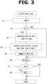
- FIG. 3 shows a main flowchart showing a purge valve control according to one embodiment.
- the routine of this main flowchart is executed in synchronization with REF signals outputted every 240° CA.
- a value of a counter N indicating the number of REF signals is read.
- the process proceeds to Step 3, where the duty ratio of the first purge valve 8A is calculated based on a requested purge gas flow rate.
- the duty ratio is a ratio of an opening time period in one cycle time, and corresponds to the width of one opening time period shown in FIG. 2 (b) .
- the duty ratio of the second purge valve 8B is equal to that of the first purge valve 8A.
- a delay T_delay is calculated, which is a delay from the start point of the opening time period of the first purge valve 8A to the start point of the opening time period of the second purge valve 8B.
- the delay T_delay is equal to ( ⁇ REF ⁇ 3.5) in one embodiment.
- Step 6 the counter N is incremented, and at Step 7, it is determined whether or not the value of the counter N has reached 8. When the value of the counter N is less than 8, the routine is terminated. When the value of the counter N has reached 8, the process proceeds to Step 8, where the value of the counter N is initialized to 1.
- FIG. 4 is a flowchart showing a control of driving timing of the second purge valve.
- the routine of FIG. 4 is executed at every minute time.
- Step 11 it is determined whether or not a driving command has been transmitted to the first purge valve 8A. In case of NO, the routine is terminated.
- a timer T is started at Step 12. In other words, the timer T is initialized to zero. Then, at Step 13, it is determined whether or not the timer T has a value greater than or equal to the delay T_delay calculated at Step 4. In case of NO, counting-up of the timer T is repeatedly executed at Step 14.
- Step 13 the process proceeds to Step 15, where a drive command is transmitted to the second purge valve 8B. Namely, one drive pulse signal is outputted to the second purge valve 8B. Thereby, as shown in FIG. 2 (b) , the second purge valve 8B opens and closes with a delay of the half cycle time from the first purge valve 8A.
- the duty control of the purge valve 8 described above may be based on the crank angle or may be based on actual time.
- FIG. 5 is an explanatory diagram showing examples of opening time periods for cases with different duty ratios.
- the second purge valve 8B (PCV2) opens the half cycle time later than the first purge valve 8A (PCV1).
- PCV1 the first purge valve 8A
- FIG. 5 only one cycle to 1.5 cycles are extracted and shown.
- Small Duty when the duty ratio is small, the opening time period of the first purge valve 8A and the opening time period of the second purge valve 8B do not overlap each other.
- “Middle Duty” when the duty ratios are equal to 50%, two opening time periods are alternate and continuous as a whole.
- the pair of purge valves 8A and 8B are alternately opened.
- a configuration is also possible in which a larger number of purge valves 8 are provided in parallel.
- the present invention may be similarly applied to a configuration in which the purge passage 5 is provided with a single purge valve 8. Namely, by setting the cycle time of drive pulsing of the single purge valve 8 to an odd multiple of ⁇ REF/2, such as ( ⁇ REF ⁇ 3.5), it is possible to produce an effect of canceling out the intake pulsation similarly as in the embodiment described above with reference to FIG. 2 .
- the interval between the start point of one opening time period and the start point of the next opening time period is equal to ( ⁇ REF ⁇ 3.5), and as shown in FIG. 2 , the first opening time period contains a section where the intake pulsation waveform descends from a peak to a valley, and the following opening time period contains a section where the intake pulsation waveform rises from a valley to a peak for the next cycle of the same cylinder.
- the present invention may be similarly applied to naturally-aspirated engines.
Landscapes
- Engineering & Computer Science (AREA)
- Chemical & Material Sciences (AREA)
- Combustion & Propulsion (AREA)
- Mechanical Engineering (AREA)
- General Engineering & Computer Science (AREA)
- Supplying Secondary Fuel Or The Like To Fuel, Air Or Fuel-Air Mixtures (AREA)
Abstract
Description
- The present invention relates to an evaporative fuel processing device employing a canister, and particularly to control of a purge valve provided in a purge passage between the canister and an intake passage of an internal combustion engine.
- Conventionally, an evaporative fuel processing device is commonly used in order to prevent evaporative fuel, which occurs in a vehicle fuel tank, from leaking outside. The evaporative fuel processing device is configured to temporarily adsorb evaporative fuel in a canister employing an adsorbent such as activated carbon, and thereafter, while an internal combustion engine is operating, purge a fuel component from the canister by introduction of fresh air, and introduce the fuel component into an intake system of the internal combustion engine. In general, the purge valve provided in the purge passage is duty-controlled at a suitable driving frequency in order to control a flow rate of purge gas introduced into an intake passage of the internal combustion engine.
- In such an evaporative fuel processing device, a quantity of purge gas is measured based on a pressure difference across a purge valve in a purge passage, and a time period in which the purge valve is opened (namely, duty ratio). However, in an intake passage to which the purge passage is connected, an intake pulsation occurs which has a cycle time depending on a number of cylinders. The intake pulsation has a relatively small influence, when an average pressure in the intake passage is sufficiently low and the pressure difference across the purge valve is large, such as when an internal combustion engine is undergoing a relatively low load.
- However, in a situation where a supercharged internal combustion engine is in a range of supercharging, or in a situation where a naturally-aspirated internal combustion engine is in a range of high load, a pressure difference (average pressure difference) across a purge valve is small so that an intake pulsation has a relatively large influence. This causes a problem that a purge gas flow rate varies depending on a relationship between the intake pulsation and a time period in which the purge valve is opened.
-
Patent Documents -
- Patent Document 1:
Japanese Utility Model Application Publication No. H5-10767 - Patent Document 2:
Japanese Patent Application Publication No. H5-332205 - According to the present invention, a purge valve control method for an evaporative fuel processing device, wherein the evaporative combustion processing device includes at least one purge valve disposed in a purge passage between a canister and an intake passage of an internal combustion engine and configured to be duty-controlled, the purge valve control method includes: synchronizing a cycle, in which the at least one purge valve is opened, with rotation of the internal combustion engine; and setting an interval at one half of an odd number times a quantity (ΔREF), wherein the interval is from a start point of a first opening time period of the at least one purge valve to a start point of a second opening time period of the at least one purge valve, wherein the second opening time period follows the first opening time period, wherein the quantity (ΔREF) is an intake stroke interval determined by a number of cylinders of the internal combustion engine.
- Inside the intake passage, an intake pulsation occurs, which has a cycle time determined by the number of cylinders connected to the intake passage. Pressure in the intake passage increases and decreases repeatedly in relation to the intake stroke of each cylinder. For example, in a simplified waveform, two adjacent peaks of the intake pulsation have an interval equal to ΔREF. Since the interval from the start point of the first opening time period to the start point of the second opening time period following the first opening time period is set equal to an odd multiple of ΔREF/2, the second opening time period starts with a valley of the intake pulsation waveform, if the first opening time period starts with a peak of the intake pulsation waveform.
- This serves to cancel the influence of intake pulsation at least partially, and thereby control the purge gas flow rate stably in accordance with the duty ratio.
-
-
FIG. 1 is an explanatory diagram showing configuration of an evaporative fuel processing device according to the present invention. -
FIG. 2 is a time chart showing a relationship between a waveform of intake pulsation and time periods in which first and second purge valves are opened. -
FIG. 3 is a main flowchart showing a purge valve control according to an embodiment. -
FIG. 4 is a flowchart showing a control of drive timing of the second purge valve. -
FIG. 5 is an explanatory diagram showing examples of opening time periods for cases with different duty ratios. - The following describes an embodiment of the present invention in detail with reference to the drawings.
FIG. 1 is an explanatory diagram schematically showing configuration of an evaporative fuel processing device in a vehicle equipped with aninternal combustion engine 1. The evaporative fuel processing device serves to process evaporative fuel, which occurs in afuel tank 2 of the vehicle while the vehicle is at rest or the like, while preventing the evaporative fuel from leaking outside. The evaporative fuel processing device is composed mainly of acanister 3 whose inside is filled with an adsorbent such as activated carbon for temporarily storing the evaporative fuel. Thecanister 3 includes an internal flow path which has acharge port 3a and apurge port 3b at its first end and adrain port 3c at its second end. Thecharge port 3a communicates with an upper space of thefuel tank 2 via a charge passage 4, whereas thepurge port 3b communicates with anintake passage 7 of theinternal combustion engine 1 via apurge passage 5. Furthermore, thedrain port 3c is opened to the atmosphere via adrain passage 6. Thedrain passage 6 may be provided with a drain cut valve not shown for leakage inspection and the like. - For example, while the vehicle is at rest or is being refueled, evaporative fuel occurs, and is introduced into the
canister 3 through the charge passage 4, and is adsorbed by adsorbents in various parts while flowing through the adsorbents toward thedrain port 3c. When atmospheric air is taken in through thedrain passage 6 by a negative pressure occurring in an intake system during operation of theinternal combustion engine 1, the thus adsorbed fuel component is purged from the adsorbents, and is introduced through thepurge passage 5 into the intake system of theinternal combustion engine 1, and is finally burnt in combustion chambers of theinternal combustion engine 1 together with fuel supplied from fuel injection valves. - In the shown example, the
internal combustion engine 1 is a four-stroke cycle spark ignition engine, such as an in-line three-cylinder turbocharged engine. Accordingly, theintake passage 7 of theinternal combustion engine 1 is provided with acompressor 11 of a turbocharger. Athrottle valve 12 is disposed downstream of thecompressor 11. Furthermore, anadmission valve 13, which is composed of a butterfly valve or the like, is disposed in theintake passage 7 upstream of thecompressor 11, for generating a negative pressure in theintake passage 7. Thepurge passage 5 has an end connected to theintake passage 7 between theadmission valve 13 and thecompressor 11. Therefore, even when in a supercharging region, some negative pressure is produced by action of theadmission valve 13, so that purging of thecanister 3, namely, introduction of purge gas into theintake passage 7, can be implemented by a pressure difference between the negative pressure and the atmospheric pressure on thedrain passage 6 side. - The
purge passage 5 is provided with a pair ofpurge valves 8, wherein eachpurge valves 8 is composed of an electromagnetic valve for purge gas flow rate control. Specifically, thepurge passage 5 includes a section branched into a pair ofpurge passages first purge valve 8A is disposed in thepurge passage 5a, and asecond purge valve 8B is disposed in thepurge passage 5b. Namely, the twopurge valves branched purge passages purge passage 5a between thepurge valve 8A and theintake passage 7 is equal in length to a section of thepurge passage 5b between thepurge valve 8B and theintake passage 7. In other words, a length of passage from the end opening of thepurge passage 5, which is connected to theintake passage 7, to thepurge valve 8A is equal to a passage length from the end opening of thepurge passage 5 to thepurge valve 8B. This results in that an intake pulsation reaching thepurge valve 8A and an intake pulsation reaching thepurge valve 8B have equivalent influences. - The
purge valves controller 9. In this example, thecontroller 9 is configured as a part of an engine controller that performs various controls of theinternal combustion engine 1, wherein the controls include a fuel injection control, an ignition control, a control of opening of thethrottle valve 12, a control of opening of theadmission valve 13, etc. - The duty control according to the present embodiment is performed such that the cycle time of opening of the
purge valves internal combustion engine 1. In other words, the driving frequency of the duty control is set to vary in accordance with the rotational speed of theinternal combustion engine 1, wherein drive pulse signals are outputted at predetermined crank angles. -
FIG. 2 is a time chart showing a relationship between (a) a waveform of intake pulsation in theintake passage 7 and (b) time periods in which the first andsecond purge valves FIG. 2 , "PCV1" and "PCV2" represent the first andsecond purge valves - The intake pulsation is caused by a process that each cylinder of the
internal combustion engine 1 intermittently undergoes its intake stroke. The cycle time or frequency of the intake pulsation is determined by the number of cylinders sharing theintake passage 7. In the four-stroke cycle in-line three-cylinder engine, intake strokes occur every 240° CA (crank angle), causing an intake pulsation with a pressure waveform peaking every 240° CA, as shown inFIG. 2 (a) . Accordingly, when expressed in terms of crank angle, an intake stroke interval ΔREF is equal to 240° CA. It is to be noted that that the waveform of intake pulsation shown inFIG. 2 (a) is in a simplified form for easy understanding. The crank angle of theinternal combustion engine 1 is sensed by a so-called crank angle sensor or cam angle sensor not shown. Based on an output signal from the sensor, a REF signal is obtained every 240° CA (crank angle) as a reference for fuel injection timing control and ignition timing control of each cylinder. In other words, the intake stroke interval ΔREF is an interval from a REF signal for a certain cylinder (for example, cylinder #1) to a REF signal for the next cylinder (for example, cylinder #2) in the ignition order. InFIG. 2 , broken lines each indicate the timing of the REF signal for each cylinder. For example, the REF signal is outputted a certain crank angle before the compression top dead center of each cylinder. In the present invention, the intake stroke interval ΔREF may be handled in actual time instead of crank angle. - Each of the
first purge valve 8A and thesecond purge valve 8B is driven at intervals of an odd multiple of ΔREF. In other words, the cycle time of the drive pulse signal is equal to an odd multiple of ΔREF. More preferably, the odd number is equal to 2·C+1, where C represents the number of cylinders. In case of the in-line three-cylinder engine according to the embodiment, the cycle time of the drive pulse signal for each of thefirst purge valve 8A and thesecond purge valve 8B is equal to seven times ΔREF. - Furthermore, the driving pulse signal for the
first purge valve 8A and the driving pulse signal for thesecond purge valve 8B have rising edges that are different from each other by half the cycle time described above. Namely, in the in-line three-cylinder engine according to the embodiment, the phase difference between each drive pulse signal of the duty control of thefirst purge valve 8A and each drive pulse signal of the duty control of thesecond purge valve 8B is equal to (ΔREF×7/2). Accordingly, for an overall purge system including the twopurge valves -
FIG. 2 (b) shows opening time periods of the first andsecond purge valves first purge valve 8A and thesecond purge valve 8B are driven with equal duty ratios. As described above, the start point of the opening time period of thefirst purge valve 8A and the start point of the opening time period of thesecond purge valve 8B are shifted from each other by half the cycle time of each purge valve, wherein the cycle time is equal to an odd multiple of ΔREF. Accordingly, as illustrated, the first opening time period of thefirst purge valve 8A contains a section in which the intake pulsation waveform falls from a peak to a valley, and the following first opening time period of thesecond purge valve 8B includes a section in which the intake pulsation waveform rises from a valley to a peak. Therefore, the influence of intake pulsation on the purge gas flow rate is substantially canceled out by thefirst purge valve 8A and thesecond purge valve 8B, wherein the purge gas flow rate depends on the pressure difference across thepurge valves - Specifically, when behavior of the intake pulsation deviates slightly back and forth with respect to REF, and the purge gas flow rate during the opening time period of the
first purge valve 8A (in the section where the intake pulsation waveform descends from a peak to a valley) decreases, the purge gas flow rate during the following opening time period of thesecond purge valve 8B (in the section where the intake pulsation waveform rises from a valley to a peak) increases. When the purge gas flow rate during the opening time period of thefirst purge valve 8A increases, the purge gas flow rate during the opening time period of thesecond purge valve 8B decreases. The behavior of the intake pulsation with respect to REF varies somewhat depending on propagation velocity of pressure waves (sound velocity in the intake passage). - Therefore, even in situations where the pressure difference (average pressure difference) across the
purge valve 8 is small, such as when in the supercharging region, it is possible to suppress the purge gas flow rate from varying due to the influence of intake pulsation, and thereby control the purge gas flow rate stably in accordance with the duty ratio. - In particular, in the embodiment described above, the opening time periods of the two
purge valves FIG. 2 , if the first opening time period of thefirst purge valve 8A contains a section of descending from a peak corresponding to thecylinder # 1 to a valley, the following opening time period of thesecond purge valve 8B contains a section of rising from a valley corresponding to thecylinder # 1 to a next peak corresponding to thecylinder # 2. Namely, it corresponds to the intake stroke of the next cycle of the same cylinder, so that, even during a transient situation in which operating conditions (rotational speed and load) of theinternal combustion engine 1 are changing, it is possible to suppress the influence of intake pulsation more accurately. Furthermore, the next opening time period of thefirst purge valve 8A contains a section of descending from a peak corresponding to thecylinder # 2 to a valley, and the following opening time period of thesecond purge valve 8B contains a section of rising from a valley corresponding to thesame cylinder # 2 to a next peak corresponding to thecylinder # 3. Furthermore, the next opening time period of thefirst purge valve 8A contains a section of descending from a peak corresponding to thecylinder # 3 to a valley, and the following opening time period of thesecond purge valve 8B contains a section of rising from a valley corresponding to thesame cylinder # 3 to a next peak corresponding to thecylinder # 1. In this way, the opening time period of thefirst purge valve 8A and the opening time period of thesecond purge valve 8B change sequentially to correspond tocylinders # 1 to #3, thereby also smoothing out effects of variation in intake pulsation among cylinders. -
FIG. 3 shows a main flowchart showing a purge valve control according to one embodiment. The routine of this main flowchart is executed in synchronization with REF signals outputted every 240° CA. AtStep 1, a value of a counter N indicating the number of REF signals is read. AtStep 2, it is determined whether or not N is equal to 1. When N is equal to 1, the process proceeds toStep 3, where the duty ratio of thefirst purge valve 8A is calculated based on a requested purge gas flow rate. The duty ratio is a ratio of an opening time period in one cycle time, and corresponds to the width of one opening time period shown inFIG. 2 (b) . In a preferred embodiment, the duty ratio of thesecond purge valve 8B is equal to that of thefirst purge valve 8A. - At Step 4, a delay T_delay is calculated, which is a delay from the start point of the opening time period of the
first purge valve 8A to the start point of the opening time period of thesecond purge valve 8B. As described above, the delay T_delay is equal to (ΔREF×3.5) in one embodiment. Then, the process proceeds toStep 5, where a driving command is transmitted to thefirst purge valve 8A. Namely, one drive pulse signal is outputted to thefirst purge valve 8A. Accordingly, thefirst purge valve 8A opens and closes as shown inFIG. 2 (b) . - Next, at
Step 6, the counter N is incremented, and atStep 7, it is determined whether or not the value of the counter N has reached 8. When the value of the counter N is less than 8, the routine is terminated. When the value of the counter N has reached 8, the process proceeds toStep 8, where the value of the counter N is initialized to 1. - When it is not determined at
Step 2 that N=1, the process proceeds fromStep 2 toStep 6. Accordingly, the process ofSteps 3 to 5 is executed only once every seven times in the routine ofFIG. 3 , so that the opening time period of thefirst purge valve 8A is set in synchronization with rotation of theinternal combustion engine 1, wherein the cycle time is equal to 7 times ΔREF. -
FIG. 4 is a flowchart showing a control of driving timing of the second purge valve. For example, the routine ofFIG. 4 is executed at every minute time. AtStep 11, it is determined whether or not a driving command has been transmitted to thefirst purge valve 8A. In case of NO, the routine is terminated. - When a driving command has been transmitted to the
first purge valve 8A, a timer T is started atStep 12. In other words, the timer T is initialized to zero. Then, atStep 13, it is determined whether or not the timer T has a value greater than or equal to the delay T_delay calculated at Step 4. In case of NO, counting-up of the timer T is repeatedly executed atStep 14. - When "T ≥ T_delay" is satisfied at
Step 13, the process proceeds to Step 15, where a drive command is transmitted to thesecond purge valve 8B. Namely, one drive pulse signal is outputted to thesecond purge valve 8B. Thereby, as shown inFIG. 2 (b) , thesecond purge valve 8B opens and closes with a delay of the half cycle time from thefirst purge valve 8A. - The duty control of the
purge valve 8 described above may be based on the crank angle or may be based on actual time. -
FIG. 5 is an explanatory diagram showing examples of opening time periods for cases with different duty ratios. As described above, thesecond purge valve 8B (PCV2) opens the half cycle time later than thefirst purge valve 8A (PCV1). InFIG. 5 , only one cycle to 1.5 cycles are extracted and shown. As indicated as "Small Duty", when the duty ratio is small, the opening time period of thefirst purge valve 8A and the opening time period of thesecond purge valve 8B do not overlap each other. As indicated as "Middle Duty", when the duty ratios are equal to 50%, two opening time periods are alternate and continuous as a whole. As indicated by "Large Duty", when the duty ratio is further larger, the opening time period of thefirst purge valve 8A and the opening time period of thesecond purge valve 8B partially overlap each other. Furthermore, "Full" indicates a case where the duty ratio is equal to 100%. - In the embodiment described above, the pair of
purge valves purge valves 8 are provided in parallel. Furthermore, the present invention may be similarly applied to a configuration in which thepurge passage 5 is provided with asingle purge valve 8. Namely, by setting the cycle time of drive pulsing of thesingle purge valve 8 to an odd multiple of ΔREF/2, such as (ΔREF×3.5), it is possible to produce an effect of canceling out the intake pulsation similarly as in the embodiment described above with reference toFIG. 2 . Specifically, the interval between the start point of one opening time period and the start point of the next opening time period is equal to (ΔREF × 3.5), and as shown inFIG. 2 , the first opening time period contains a section where the intake pulsation waveform descends from a peak to a valley, and the following opening time period contains a section where the intake pulsation waveform rises from a valley to a peak for the next cycle of the same cylinder. - It is to be noted that in cases where a pair of
purge valves purge valves single purge valve 8 is employed, there is an advantage that it is possible to employ a small-capacity solenoid valve which is highly responsive in general. - Furthermore, although the above embodiment is an application to a supercharged engine equipped with a turbocharger, the present invention may be similarly applied to naturally-aspirated engines.
Claims (7)
- A purge valve control method for an evaporative fuel processing device, wherein the evaporative combustion processing device includes at least one purge valve disposed in a purge passage between a canister and an intake passage of an internal combustion engine and configured to be duty-controlled, the purge valve control method comprising:synchronizing a cycle, in which the at least one purge valve is opened, with rotation of the internal combustion engine; andsetting an interval at one half of an odd number times a quantity (ΔREF), wherein the interval is from a start point of a first opening time period of the at least one purge valve to a start point of a second opening time period of the at least one purge valve, wherein the second opening time period follows the first opening time period, wherein the quantity (ΔREF) is an intake stroke interval determined by a number of cylinders of the internal combustion engine.
- The purge valve control method as claimed in claim 1, wherein the at least one purge valve includes a first purge valve and a second purge valve, wherein the first purge valve and the second purge valve are arranged in parallel with each other, the purge valve control method comprising:
opening the first purge valve and the second purge valve alternately such that the interval set at the one half of the odd number times the quantity is from a start point of an opening time period of the first purge valve to a start point of an opening time period of the second purge valve, wherein the opening time period of the second purge valve follows the opening time period of the first purge valve. - The purge valve control method as claimed in claim 2, comprising:
driving the first purge valve and the second purge valve at equal duty ratios. - The purge valve control method as claimed in claim 2 or 3, wherein the purge passage includes a first purge passage section from the intake passage to the first purge valve, and a second purge passage section from the intake passage to the second purge valve, the purge valve control method comprising:
setting the first purge passage section and the second purge passage section equal in length to each other. - The purge valve control method as claimed in any one of claims 1 to 4, comprising:
setting the odd number to (2.C+1), wherein C represents the number of cylinders of the internal combustion engine. - The purge valve control method as claimed in any one of claims 1 to 5, comprising:
setting the first opening time period and the second opening time period such that a waveform of intake pulsation has a peak in the first opening time period and has a valley in the second opening time period. - A purge valve control device for an evaporative fuel processing device, comprising:a canister structured to adsorb evaporative fuel;at least one purge valve disposed in a purge passage between the canister and an intake passage of an internal combustion engine; anda controller configured to duty-control the at least one purge valve;wherein the controller is configured to drive the at least one purge valve by:synchronizing a cycle, in which the at least one purge valve is opened, with rotation of the internal combustion engine; andsetting an interval at one half of an odd number times a quantity (ΔREF), wherein the interval is from a start point of a first opening time period of the at least one purge valve to a start point of a second opening time period of the at least one purge valve, wherein the second opening time period follows the first opening time period, wherein the quantity (ΔREF) is an intake stroke interval determined by a number of cylinders of the internal combustion engine.
Applications Claiming Priority (1)
| Application Number | Priority Date | Filing Date | Title |
|---|---|---|---|
| PCT/JP2021/043105 WO2023095225A1 (en) | 2021-11-25 | 2021-11-25 | Purge valve control method and control device of evaporated fuel processing device |
Publications (2)
| Publication Number | Publication Date |
|---|---|
| EP4438885A1 true EP4438885A1 (en) | 2024-10-02 |
| EP4438885A4 EP4438885A4 (en) | 2025-01-01 |
Family
ID=86539101
Family Applications (1)
| Application Number | Title | Priority Date | Filing Date |
|---|---|---|---|
| EP21964983.7A Withdrawn EP4438885A4 (en) | 2021-11-25 | 2021-11-25 | VENT VALVE CONTROL METHOD AND CONTROL DEVICE FOR A EVAPORATORY FUEL PROCESSING DEVICE |
Country Status (4)
| Country | Link |
|---|---|
| EP (1) | EP4438885A4 (en) |
| JP (1) | JP7609299B2 (en) |
| CN (1) | CN118234935A (en) |
| WO (1) | WO2023095225A1 (en) |
Family Cites Families (11)
| Publication number | Priority date | Publication date | Assignee | Title |
|---|---|---|---|---|
| US5060621A (en) * | 1989-08-28 | 1991-10-29 | Ford Motor Company | Vapor purge control system |
| JPH0510767U (en) | 1991-07-18 | 1993-02-12 | 本田技研工業株式会社 | Duty control type flow control device |
| JPH05332205A (en) * | 1992-06-01 | 1993-12-14 | Toyota Motor Corp | Evaporative fuel processor |
| JP2860851B2 (en) * | 1993-02-05 | 1999-02-24 | 株式会社ユニシアジェックス | Evaporative fuel control system for internal combustion engine |
| JPH06272628A (en) * | 1993-03-18 | 1994-09-27 | Mitsubishi Electric Corp | Evaporative fuel control device for engine |
| JP3277767B2 (en) * | 1995-09-22 | 2002-04-22 | 日産自動車株式会社 | Evaporative fuel treatment system for internal combustion engine |
| JP4045771B2 (en) | 2001-10-11 | 2008-02-13 | 日産自動車株式会社 | Evaporative fuel processing device for internal combustion engine |
| EP1406005B1 (en) * | 2002-09-20 | 2006-04-19 | Ford Global Technologies, Inc. | Method and apparatus for monitoring a controllable valve |
| JP2004270627A (en) | 2003-03-11 | 2004-09-30 | Toyota Motor Corp | Control device for variable cylinder internal combustion engine |
| JP6176125B2 (en) * | 2014-01-17 | 2017-08-09 | 株式会社デンソー | Purge control device |
| JP2019060287A (en) * | 2017-09-27 | 2019-04-18 | 浜名湖電装株式会社 | Purge valve and evaporated fuel processing device |
-
2021
- 2021-11-25 WO PCT/JP2021/043105 patent/WO2023095225A1/en not_active Ceased
- 2021-11-25 EP EP21964983.7A patent/EP4438885A4/en not_active Withdrawn
- 2021-11-25 JP JP2023563399A patent/JP7609299B2/en active Active
- 2021-11-25 CN CN202180104252.7A patent/CN118234935A/en active Pending
Also Published As
| Publication number | Publication date |
|---|---|
| JP7609299B2 (en) | 2025-01-07 |
| EP4438885A4 (en) | 2025-01-01 |
| JPWO2023095225A1 (en) | 2023-06-01 |
| WO2023095225A1 (en) | 2023-06-01 |
| CN118234935A (en) | 2024-06-21 |
Similar Documents
| Publication | Publication Date | Title |
|---|---|---|
| EP1999356B1 (en) | Acceleration request determining system and method, and control system and control method of internal combustion engine | |
| CN101573517B (en) | Control device and control method for internal combustion engine | |
| US9638119B2 (en) | Control apparatus and control method for an internal combustion engine | |
| EP2514952A1 (en) | Control device for internal-combustion engine | |
| US9976510B2 (en) | Fuel injection control apparatus | |
| US20170145946A1 (en) | Control device for internal combustion engine | |
| US9181894B2 (en) | Control system for internal combustion engine | |
| JP7700743B2 (en) | Control device for internal combustion engine | |
| JP2006283636A (en) | Engine control device | |
| US7357127B2 (en) | Method for determining the air mass in a cylinder | |
| US8006676B2 (en) | Control device for engine | |
| JP2013253500A (en) | Control device for internal combustion engine | |
| US9611796B2 (en) | Control apparatus for direct injection engine | |
| US5515832A (en) | Method of controlling internal combustion engine exhaust hydrocarbons | |
| US12305589B2 (en) | Fuel injection control device for internal combustion engine | |
| JP7609299B2 (en) | Method and control device for controlling purge valve of evaporated fuel treatment device | |
| RU2633298C2 (en) | Operation method of turbocharger (versions) | |
| JP2021169782A (en) | Engine equipment | |
| JP7003494B2 (en) | Engine control | |
| JPH04124450A (en) | Evaporated fuel gas purge control device | |
| US20160369729A1 (en) | Control apparatus and control method for internal combustion engine | |
| JP2008303745A (en) | Control device for internal combustion engine | |
| JP7754040B2 (en) | Ignition timing control device for internal combustion engine | |
| JP7722309B2 (en) | Ignition timing control device for internal combustion engine | |
| US10550771B2 (en) | Control device of internal-combustion engine |
Legal Events
| Date | Code | Title | Description |
|---|---|---|---|
| STAA | Information on the status of an ep patent application or granted ep patent |
Free format text: STATUS: THE INTERNATIONAL PUBLICATION HAS BEEN MADE |
|
| PUAI | Public reference made under article 153(3) epc to a published international application that has entered the european phase |
Free format text: ORIGINAL CODE: 0009012 |
|
| STAA | Information on the status of an ep patent application or granted ep patent |
Free format text: STATUS: REQUEST FOR EXAMINATION WAS MADE |
|
| 17P | Request for examination filed |
Effective date: 20240528 |
|
| AK | Designated contracting states |
Kind code of ref document: A1 Designated state(s): AL AT BE BG CH CY CZ DE DK EE ES FI FR GB GR HR HU IE IS IT LI LT LU LV MC MK MT NL NO PL PT RO RS SE SI SK SM TR |
|
| A4 | Supplementary search report drawn up and despatched |
Effective date: 20241129 |
|
| RIC1 | Information provided on ipc code assigned before grant |
Ipc: F02D 41/00 20060101ALI20241125BHEP Ipc: F02M 25/08 20060101AFI20241125BHEP |
|
| DAV | Request for validation of the european patent (deleted) | ||
| DAX | Request for extension of the european patent (deleted) | ||
| STAA | Information on the status of an ep patent application or granted ep patent |
Free format text: STATUS: THE APPLICATION HAS BEEN WITHDRAWN |
|
| 18W | Application withdrawn |
Effective date: 20250403 |