EP4438877A1 - Igniter for a gas turbine - Google Patents
Igniter for a gas turbine Download PDFInfo
- Publication number
- EP4438877A1 EP4438877A1 EP24167657.6A EP24167657A EP4438877A1 EP 4438877 A1 EP4438877 A1 EP 4438877A1 EP 24167657 A EP24167657 A EP 24167657A EP 4438877 A1 EP4438877 A1 EP 4438877A1
- Authority
- EP
- European Patent Office
- Prior art keywords
- conductor
- igniter
- tip
- axis
- magnetic field
- Prior art date
- Legal status (The legal status is an assumption and is not a legal conclusion. Google has not performed a legal analysis and makes no representation as to the accuracy of the status listed.)
- Pending
Links
- 239000004020 conductor Substances 0.000 claims abstract description 90
- 239000012212 insulator Substances 0.000 claims abstract description 38
- 238000002485 combustion reaction Methods 0.000 claims description 32
- 238000004891 communication Methods 0.000 claims description 4
- 239000007789 gas Substances 0.000 description 10
- 238000012545 processing Methods 0.000 description 7
- 239000003570 air Substances 0.000 description 6
- 230000000694 effects Effects 0.000 description 5
- 230000006870 function Effects 0.000 description 4
- 239000000463 material Substances 0.000 description 4
- 238000005260 corrosion Methods 0.000 description 3
- 230000007797 corrosion Effects 0.000 description 3
- 238000005516 engineering process Methods 0.000 description 3
- 239000000567 combustion gas Substances 0.000 description 2
- 238000013461 design Methods 0.000 description 2
- 230000005684 electric field Effects 0.000 description 2
- 239000000446 fuel Substances 0.000 description 2
- 230000001788 irregular Effects 0.000 description 2
- 238000000034 method Methods 0.000 description 2
- 239000000203 mixture Substances 0.000 description 2
- 238000012986 modification Methods 0.000 description 2
- 230000004048 modification Effects 0.000 description 2
- 230000008569 process Effects 0.000 description 2
- 238000004804 winding Methods 0.000 description 2
- XUIMIQQOPSSXEZ-UHFFFAOYSA-N Silicon Chemical compound [Si] XUIMIQQOPSSXEZ-UHFFFAOYSA-N 0.000 description 1
- 230000009471 action Effects 0.000 description 1
- 239000012080 ambient air Substances 0.000 description 1
- 230000015556 catabolic process Effects 0.000 description 1
- 230000006835 compression Effects 0.000 description 1
- 238000007906 compression Methods 0.000 description 1
- 238000010586 diagram Methods 0.000 description 1
- 238000006073 displacement reaction Methods 0.000 description 1
- 239000000835 fiber Substances 0.000 description 1
- 230000006872 improvement Effects 0.000 description 1
- 239000000615 nonconductor Substances 0.000 description 1
- 238000004382 potting Methods 0.000 description 1
- 238000012552 review Methods 0.000 description 1
- 230000011664 signaling Effects 0.000 description 1
- 229910052710 silicon Inorganic materials 0.000 description 1
- 239000010703 silicon Substances 0.000 description 1
Images




Classifications
-
- H—ELECTRICITY
- H01—ELECTRIC ELEMENTS
- H01T—SPARK GAPS; OVERVOLTAGE ARRESTERS USING SPARK GAPS; SPARKING PLUGS; CORONA DEVICES; GENERATING IONS TO BE INTRODUCED INTO NON-ENCLOSED GASES
- H01T13/00—Sparking plugs
- H01T13/20—Sparking plugs characterised by features of the electrodes or insulation
- H01T13/22—Sparking plugs characterised by features of the electrodes or insulation having two or more electrodes embedded in insulation
-
- F—MECHANICAL ENGINEERING; LIGHTING; HEATING; WEAPONS; BLASTING
- F02—COMBUSTION ENGINES; HOT-GAS OR COMBUSTION-PRODUCT ENGINE PLANTS
- F02C—GAS-TURBINE PLANTS; AIR INTAKES FOR JET-PROPULSION PLANTS; CONTROLLING FUEL SUPPLY IN AIR-BREATHING JET-PROPULSION PLANTS
- F02C7/00—Features, components parts, details or accessories, not provided for in, or of interest apart form groups F02C1/00 - F02C6/00; Air intakes for jet-propulsion plants
- F02C7/26—Starting; Ignition
- F02C7/264—Ignition
-
- F—MECHANICAL ENGINEERING; LIGHTING; HEATING; WEAPONS; BLASTING
- F02—COMBUSTION ENGINES; HOT-GAS OR COMBUSTION-PRODUCT ENGINE PLANTS
- F02C—GAS-TURBINE PLANTS; AIR INTAKES FOR JET-PROPULSION PLANTS; CONTROLLING FUEL SUPPLY IN AIR-BREATHING JET-PROPULSION PLANTS
- F02C7/00—Features, components parts, details or accessories, not provided for in, or of interest apart form groups F02C1/00 - F02C6/00; Air intakes for jet-propulsion plants
- F02C7/26—Starting; Ignition
- F02C7/264—Ignition
- F02C7/266—Electric
-
- F—MECHANICAL ENGINEERING; LIGHTING; HEATING; WEAPONS; BLASTING
- F02—COMBUSTION ENGINES; HOT-GAS OR COMBUSTION-PRODUCT ENGINE PLANTS
- F02K—JET-PROPULSION PLANTS
- F02K9/00—Rocket-engine plants, i.e. plants carrying both fuel and oxidant therefor; Control thereof
- F02K9/95—Rocket-engine plants, i.e. plants carrying both fuel and oxidant therefor; Control thereof characterised by starting or ignition means or arrangements
-
- H—ELECTRICITY
- H01—ELECTRIC ELEMENTS
- H01T—SPARK GAPS; OVERVOLTAGE ARRESTERS USING SPARK GAPS; SPARKING PLUGS; CORONA DEVICES; GENERATING IONS TO BE INTRODUCED INTO NON-ENCLOSED GASES
- H01T13/00—Sparking plugs
- H01T13/20—Sparking plugs characterised by features of the electrodes or insulation
-
- H—ELECTRICITY
- H01—ELECTRIC ELEMENTS
- H01T—SPARK GAPS; OVERVOLTAGE ARRESTERS USING SPARK GAPS; SPARKING PLUGS; CORONA DEVICES; GENERATING IONS TO BE INTRODUCED INTO NON-ENCLOSED GASES
- H01T13/00—Sparking plugs
- H01T13/20—Sparking plugs characterised by features of the electrodes or insulation
- H01T13/32—Sparking plugs characterised by features of the electrodes or insulation characterised by features of the earthed electrode
-
- H—ELECTRICITY
- H01—ELECTRIC ELEMENTS
- H01T—SPARK GAPS; OVERVOLTAGE ARRESTERS USING SPARK GAPS; SPARKING PLUGS; CORONA DEVICES; GENERATING IONS TO BE INTRODUCED INTO NON-ENCLOSED GASES
- H01T13/00—Sparking plugs
- H01T13/40—Sparking plugs structurally combined with other devices
-
- H—ELECTRICITY
- H01—ELECTRIC ELEMENTS
- H01T—SPARK GAPS; OVERVOLTAGE ARRESTERS USING SPARK GAPS; SPARKING PLUGS; CORONA DEVICES; GENERATING IONS TO BE INTRODUCED INTO NON-ENCLOSED GASES
- H01T13/00—Sparking plugs
- H01T13/40—Sparking plugs structurally combined with other devices
- H01T13/41—Sparking plugs structurally combined with other devices with interference suppressing or shielding means
-
- H—ELECTRICITY
- H01—ELECTRIC ELEMENTS
- H01T—SPARK GAPS; OVERVOLTAGE ARRESTERS USING SPARK GAPS; SPARKING PLUGS; CORONA DEVICES; GENERATING IONS TO BE INTRODUCED INTO NON-ENCLOSED GASES
- H01T13/00—Sparking plugs
- H01T13/40—Sparking plugs structurally combined with other devices
- H01T13/42—Sparking plugs structurally combined with other devices with magnetic spark generators
-
- H—ELECTRICITY
- H01—ELECTRIC ELEMENTS
- H01T—SPARK GAPS; OVERVOLTAGE ARRESTERS USING SPARK GAPS; SPARKING PLUGS; CORONA DEVICES; GENERATING IONS TO BE INTRODUCED INTO NON-ENCLOSED GASES
- H01T13/00—Sparking plugs
- H01T13/50—Sparking plugs having means for ionisation of gap
-
- H—ELECTRICITY
- H01—ELECTRIC ELEMENTS
- H01T—SPARK GAPS; OVERVOLTAGE ARRESTERS USING SPARK GAPS; SPARKING PLUGS; CORONA DEVICES; GENERATING IONS TO BE INTRODUCED INTO NON-ENCLOSED GASES
- H01T13/00—Sparking plugs
- H01T13/52—Sparking plugs characterised by a discharge along a surface
-
- F—MECHANICAL ENGINEERING; LIGHTING; HEATING; WEAPONS; BLASTING
- F05—INDEXING SCHEMES RELATING TO ENGINES OR PUMPS IN VARIOUS SUBCLASSES OF CLASSES F01-F04
- F05D—INDEXING SCHEME FOR ASPECTS RELATING TO NON-POSITIVE-DISPLACEMENT MACHINES OR ENGINES, GAS-TURBINES OR JET-PROPULSION PLANTS
- F05D2250/00—Geometry
- F05D2250/30—Arrangement of components
- F05D2250/31—Arrangement of components according to the direction of their main axis or their axis of rotation
- F05D2250/311—Arrangement of components according to the direction of their main axis or their axis of rotation the axes being in line
-
- F—MECHANICAL ENGINEERING; LIGHTING; HEATING; WEAPONS; BLASTING
- F05—INDEXING SCHEMES RELATING TO ENGINES OR PUMPS IN VARIOUS SUBCLASSES OF CLASSES F01-F04
- F05D—INDEXING SCHEME FOR ASPECTS RELATING TO NON-POSITIVE-DISPLACEMENT MACHINES OR ENGINES, GAS-TURBINES OR JET-PROPULSION PLANTS
- F05D2250/00—Geometry
- F05D2250/30—Arrangement of components
- F05D2250/31—Arrangement of components according to the direction of their main axis or their axis of rotation
- F05D2250/312—Arrangement of components according to the direction of their main axis or their axis of rotation the axes being parallel to each other
-
- F—MECHANICAL ENGINEERING; LIGHTING; HEATING; WEAPONS; BLASTING
- F05—INDEXING SCHEMES RELATING TO ENGINES OR PUMPS IN VARIOUS SUBCLASSES OF CLASSES F01-F04
- F05D—INDEXING SCHEME FOR ASPECTS RELATING TO NON-POSITIVE-DISPLACEMENT MACHINES OR ENGINES, GAS-TURBINES OR JET-PROPULSION PLANTS
- F05D2250/00—Geometry
- F05D2250/30—Arrangement of components
- F05D2250/36—Arrangement of components in inner-outer relationship, e.g. shaft-bearing arrangements
-
- F—MECHANICAL ENGINEERING; LIGHTING; HEATING; WEAPONS; BLASTING
- F23—COMBUSTION APPARATUS; COMBUSTION PROCESSES
- F23Q—IGNITION; EXTINGUISHING-DEVICES
- F23Q3/00—Igniters using electrically-produced sparks
- F23Q3/006—Details
Definitions
- the application relates generally to gas turbine engines and, more particularly, to igniters.
- Igniters such as "spark plugs" are well known to the field of combustion engines and are used in the ignition of the mixture air and gas. In a gas turbine engine, once combustion is established in the combustor, the combustion may then typically sustain itself without the action of the igniter during a period of operation.
- One of the challenges associated to igniters is that they typically have an igniting portion, or tip, which is exposed to the combustion chamber.
- the combustion chamber can reach high temperatures during engine operation, especially in the case of some gas turbine engines.
- the igniter therefore needs to be resilient to the high temperatures which can be expected during operation of the igniter.
- the igniter may also need to be resilient to corrosion which may be spurred by higher temperatures, as corrosion may lead to a decrease in spark efficiency.
- igniters were satisfactory to a certain degree, there always remains room for improvement. In particular, even good igniters are expected to fail after a specific failure life span and loss of spark efficiency can be expected over time due to factors such as corrosion stemming from the repeated combustions in the vicinity of the igniter.
- an igniter comprising a first conductor extending along a length of the igniter; a second conductor extending alongside and spaced apart from the first conductor; an insulator filling a space between a portion of the first conductor and a portion of the second conductor, with a tip of the first conductor protruding from the insulator and forming a positive terminal, and a tip of the second conductor positioned adjacent the tip of the first conductor and forming a negative terminal; a spark path extending from the positive terminal to the negative terminal; an electromagnet embedded within the insulator, between the first conductor and the second conductor, and having a magnetic field axis extending from a north pole to a south pole, the magnetic field axis extending transversally relative the spark path.
- a portion of the magnetic field B extending at the spark path has a counter-clockwise direction relative the axis when viewed in an axial direction extending from the spark path towards the at least one magnet.
- the at least one magnet includes a plurality of magnets interspaced from one another circumferentially relative the axis, each magnet of the plurality of magnets having a length extending tangentially relative the axis, a north pole oriented clockwise relative the axis, and a south pole oriented counter-clockwise relative the axis when viewed in an axial direction extending from the spark path towards the at least one magnet.
- the igniter further comprising a plurality of insulator elements, each insulator element located circumferentially between a corresponding pair of magnets of the plurality of magnets, and intersecting the spark path.
- the at least one magnet is at least one electromagnet.
- the at least one magnet is at least one permanent magnet.
- a gas turbine engine comprising in serial flow communication a compression section, a combustor, and a turbine section, and an ignition subsystem having at least one igniter, the at least one igniter having a first conductor having a tip extending along an axis and forming a positive terminal, the tip of the first conductor exposed to a combustion chamber in the combustor; a second conductor having a tip surrounding the tip of the first conductor around the axis and forming a negative terminal, the tip of the second conductor exposed to a combustion chamber in the combustor; an insulator filling a space between the first conductor and the second conductor, with the tip of the first conductor and the tip of the second conductor protruding from the insulator; a spark path extending radially, relative the axis, between the tip of the first conductor and the tip of the second conductor, from the positive terminal to the negative terminal; and at least one magnet operable to generate a magnetic field B,
- a portion of the magnetic field B extending at the spark path has a counter-clockwise direction relative the axis when viewed from the combustion chamber.
- the at least one magnet includes a plurality of magnets interspaced from one another circumferentially relative the axis, each magnet of the plurality of magnets having a length extending tangentially relative the axis, a north pole oriented clockwise relative the axis, and a south pole oriented counter-clockwise relative the axis when viewed in an axial direction extending from the spark path towards the at least one magnet.
- the gas turbine engine further comprises a plurality of insulator elements, each insulator element located circumferentially between a corresponding pair of magnets of the plurality of magnets, and intersecting the spark path.
- the at least one magnet is at least one electromagnet.
- the at least one magnet is at least one permanent magnet.
- the ignition subsystem further comprises at least one voltage source, a voltage regulator connected between the at least one voltage source and the first conductor; and an exciter connected between the at least one voltage source and the positive terminal.
- the second conductor and the negative terminal are grounded.
- the voltage regulator and the exciter are integrated to a body of the igniter.
- the at least one voltage source is a single voltage source having a positive terminal connected to both the voltage regulator and the exciter.
- an igniter comprising a first conductor having a tip extending along an axis and forming a positive terminal; a second conductor having a tip surrounding the tip of the first conductor around the axis and forming a negative terminal; an insulator filling a space between the first conductor and the second conductor, with the tip of the first conductor and the tip of the second conductor protruding from the insulator; a spark path extending radially, relative the axis, between the tip of the first conductor and the tip of the second conductor, from the positive terminal to the negative terminal; and at least one magnet operable to generate a magnetic field B, the magnetic field B having a magnetic field orientation extending circumferentially around the axis, the at least one magnet disposed radially, relative the axis, between the first conductor and the second conductor, the at least one magnet embedded within the insulator.
- the north pole is oriented towards a right hand side relative a direction of the spark path.
- the igniter further comprises at least one voltage source, a voltage regulator connected between the at least one voltage source and the first conductor; and an exciter connected between the at least one voltage source and the positive terminal.
- the second conductor and the negative terminal are grounded.
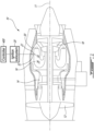
- Fig. 1 illustrates a gas turbine engine 10 of a type preferably provided for use in subsonic flight, generally comprising in serial flow communication a fan 12 through which ambient air is propelled, a compressor section 14 for pressurizing the air, a combustor 16 in which the compressed air is mixed with fuel and ignited for generating an annular stream of hot combustion gases around the engine axis 11, and a turbine section 18 for extracting energy from the combustion gases.
- a gas turbine engine 10 of a type preferably provided for use in subsonic flight, generally comprising in serial flow communication a fan 12 through which ambient air is propelled, a compressor section 14 for pressurizing the air, a combustor 16 in which the compressed air is mixed with fuel and ignited for generating an annular stream of hot combustion gases around the engine axis 11, and a turbine section 18 for extracting energy from the combustion gases.
- the gas turbine engine 10 further comprises an ignition subsystem 20 which can include one or more igniters 22 associated to the combustor 16, with an igniting portion 24 or tip of the igniter(s) exposed to the one or more combustion chambers 26 enclosed by the combustor.
- the ignition subsystem 20 can be controlled by a controller 400, which may be or include a computer.
- the combustion chamber 26 enclosed by the combustor 16 is an area where combustion occurs, and the temperature and pressure may be very high in this area.
- cooler air is circulated around the combustor 16, such as between the combustor 16 and an engine casing 30, and has the effect of controlling the temperature of the combustor 16.
- the igniter 22 can have a body including a portion which is secured to the combustor 16 or engine casing 30 and an igniting portion 24 which is exposed to the combustion chamber 26 inside the combustor 16.
- a portion 32 of the igniter can be withdrawn into the cooler air circulated around the combustor 16, such as between the combustor 16 and the engine casing 30, to manage the temperature of the igniter 22 throughout the operating envelope.
- the igniting portion 24 or tip of the igniter is typically within the combustor 16 and exposed to the combustion chamber 26.
- the portion 32 of the igniter 22 which is withdrawn from the combustion chamber 26 can be configured to act as a heat sink.
- the igniter 122 is of a type having a igniting portion 124 generally cylindrical geometry with a first conductor 134 leading to a tip 136 in the form of a central pin, and a second conductor 138 leading to a tip 140 in the form of an annulus surrounding the central pin.
- the tip of the first conductor 134, or central pin is used as a positive terminal during use, and is thus an electrically positive terminal.
- the tip of the second conductor 140, or annulus (or shell) is used as a negative terminal during use and is thus an electrically negative terminal.
- An insulator 142 fills a space between the first conductor 134 and the second conductor 138.
- the insulator 142 can be both an electrical insulator and a thermal insulator and can be embodied in the form of a potting.
- a spark path 144 extends from the positive terminal to the negative terminal. Indeed, during use, a spark consisting of electrons travelling across the ambient media may be generated when the voltage between the positive terminal and the negative terminal exceeds the dielectric resistance of the media and leads to dielectric breakdown of the media.
- the media can be the air/fuel mixture.
- the spark path 144 taken by the electrons may be the most direct path between the positive terminal and the negative terminal, where the electrical field will be the strongest. In a context such as this one where the annulus is centered around the central pin, the arc may randomly choose one angle amongst the multitude of different angles it could take.
- spark path 144 in this context can refer to the annular region representing the multiple possible angles from the positive terminal to the negative terminal.
- the individual arc paths are straight and the spark path 144 can thus be disc-shaped.
- Fig. 2B presents a second embodiment of an igniter 22.
- the elements described above with respect to Fig. 2A can all be present.
- cylindrical coordinates to define an axial orientation 46 coinciding here with the tip of the first conductor 36.
- a circumferentially-oriented magnetic field B is provided at the spark path 44.
- this force will be either axially inward, i.e. towards the insulator, or axially outward, i.e. into the combustion chamber.
- the force may thus be generated axially outwardly, curving the spark path into a toroidal surface section and forcing the electrons of the arc to curve deeper into the combustion chamber on their way to the negative terminal as shown.
- this spark path curving effect may allow to retract the tip of the igniter from the combustion chamber to a somewhat lower temperature region, and thereby alleviate the thermally-imparted constraints on the design of the igniter and/or improve its durability.
- Such a circumferentially oriented magnetic field B may be generated by one or more magnet 48 which are integrated to the igniter 22, and which may more specifically be embedded within the insulator 42, radially between the first conductor 34 and the second conductor 38, and axially offset/retracted relative the tips 36, 40.
- a plurality of magnets such as 3, 4, 5, 6 or more magnets for instance, can be circumferentially aligned relative one another, around the central pin, and embedded within the insulator.
- the magnets 48 which can be electromagnets, may have individual magnetic field axes extending between a north pole N and a south pole S, and these magnetic field axes can be oriented circumferentially, or tangentially, relative the axis 46.
- FIG. 3 Taking the example of an electromagnet 248 formed with a coil wrapped around a magnetic field axis.
- current circulating in the electric wire will generate a magnetic field circumferential to the length of the wire.
- the magnetic field generated by the different windings add up and generate a high magnetic field strength oriented along the magnetic field axis 252.
- a magnetic core (not shown for simplicity) may be provided within the winding, along the magnetic field axis 252, to both facilitate the wrapping of the coil and amplify the magnetic field strength.
- the magnetic field B will either exit one end of the coil or the other, defining a north pole N and a south pole P.
- the upper portion of the coil comes out from the page, the lower portion of the coil goes into the page, the positive terminal is at the left and the negative is at the right, leading to a north pole N on the right side and a south pole S on the right side.
- the magnetic field lines close back from the north pole N to the south pole S outside the core in a region of magnetic field strength which diminishes as the location is farther and farther away from the coil 252.
- a first conductor 234 in the form of an elongated positive terminal or anode (+) and a second conductor 238 in the form of an elongated negative terminal or cathode (-) are shown, with the electromagnet 248 provided between the positive terminal and the negative terminal, and normal to both i) the orientation of the positive terminal or negative terminal, and ii) the electric field orientation extending between the negative terminal and the positive terminal.
- the electrons Upon travelling from the positive tip to the negative tip, the electrons will be subjected to an electric force qE driving their motion in the orientation qv between the positive tip and the negative tip.
- the electrons which represent charges in motion, will further be subjected to a magnetic force F m .
- the amplitude and orientation of the magnetic force F m will correspond to the vector cross product of the magnetic charge velocity qv and of the magnetic field orientation B at their instantaneous position.
- the resulting magnetic force F m will be in the orientation away from the electromagnet, as per the arrow shown in Fig. 3 .
- the resulting path which will be taken by the electrons will be the result of the combination between the electrical and magnetic forces and will curve away from the electromagnet before coming back at the negative terminal. If the coil 248 was wound in the opposite direction, the north pole N and the south pole S would be inversed, and the resulting magnetic force would be in the orientation towards the electromagnet, which would not have the effect of "pushing" the spark deeper into the combustion chamber.
- the direction of the magnetic field B can be selected to be counter-clockwise (i.e. a counter-clockwise circumferential direction) around the axis 46 when viewed in an axial direction from the spark path to the at least one magnet (i.e. looking at the tip of the igniter from the combustion chamber), to lead to pushing of the spark path deeper into the combustion chamber by the magnetic field, independently of which angle around the axis 46 the spark actually takes as it travels from the positive terminal to the negative terminal.
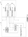
- Fig. 4 presents an example schematic of an igniter subsystem 20 which may be associated to an igniter 22 such as shown in Fig. 2B , except that in the simplified schematic of Fig. 4 , only two electromagnets 48, rather than four, are schematized.
- a single voltage supply 60 is used to drive both the electromagnets 48 and the sparks (positive terminal/negative terminal).
- a positive terminal of the voltage source 60 can be connected to an exciter box or exciter 62, which leads to the positive terminal, and to a voltage regulator 64, which leads to a positive terminal of the electromagnets 48.
- a negative terminal of the electromagnets 48, of the voltage supply, and the negative terminal, may be grounded.
- the voltage regulator 64 can have the role of supplying a controlled, moderate, voltage across the electromagnets 48 in a manner, for instance, to generate a relatively stable magnetic field of an appropriate strength for pushing the spark into the combustion chamber by an appropriate amount.
- the exciter 62 can have the role of accumulating a very high voltage and to then discharge a strong current as a spark. Either one, or more than one of the voltage regulator 64, exciter 62 and voltage supply 60 may be controlled by a controller 400.
- the components of the igniter subsystem 20 such as the voltage supply 60 and exciter may be included as part of a body of the igniter itself, such as a portion 32 of the igniter 22 which is maintained away from the highest temperature regions of the combustion chamber 26 throughout operation, in which case a single electrical connection may be used as the voltage supply 60.
- the voltage supply and exciter may be embodied as part of a component which is distinct from the igniter, and electrically connected thereto.
- the voltage regulator and/or the exciter may be omitted or substituted by one or more other suitable components.
- the voltage regulator and the exciter can be connectable via distinct electrical terminals.
- magnets 48 may be used. For instance, there may be 6 magnets, 8 magnets, or still a different number of magnets 48.
- the magnets may be circumferentially aligned with one another, with the north poles all pointing clockwise (having a clockwise circumferential direction) and the south poles all pointing counter-clockwise (having a counter-clockwise circumferential direction) when viewed from the combustion chamber.
- the overall magnetic field while still generally having a "counter-clockwise" direction when taking the individual magnets collectively, will be irregular and in particular, will have regions of significantly weaker magnetic field, interspersed circumferentially with the magnets. More specifically, represented schematically here by dashed-line cylinders, regions of weaker magnetic field 49 will be present circumferentially at circumferential positions corresponding to gaps between corresponding adjacent pairs of magnets 48. Referring back to Fig. 3 , these regions of weaker magnetic field 249 are associated with corresponding ends of the magnets, where the magnetic field lines close back towards the core rather than extending parallel to the core.
- a spark travelling above either one of the magnets 48 may be suitably deflected outwardly by the magnetic field
- a spark travelling across either one of the regions of weaker magnetic field 49 may be less suitably deflected outwardly given the weaker or differently oriented magnetic field. It may be preferred to impede sparks from forming in the regions of weaker magnetic field 49.
- Figs. 5A and 5B present two example ways of addressing this.
- the annular tip 340 of the second conductor has a plurality of insulating caps 349.
- the insulating caps 349 are located circumferentially between corresponding pairs of the magnets 348, at an axial position of the spark path, and are configured to prevent a spark from extending across a region of weaker magnetic field 49.
- the plurality of insulating caps 349 constitute a plurality of insulator elements, each insulator element located circumferentially between a corresponding pair of magnets 348 of the plurality of magnets, and intersecting the spark path.
- the insulator 342 itself is provided with an irregular shape. More specifically, the tip of the insulator 342 is crenellated, and has a plurality of crenels protruding axially, between the annular tip 340 of the second conductor and the central tip 346 of the first conductor. The crenels are located circumferentially between corresponding pairs of the magnets 348, at an axial position of the spark path, and are configured to prevent a spark from extending across a region of weaker magnetic field. Accordingly, the protruding crenels constitute a plurality of insulator elements, each insulator element located circumferentially between a corresponding pair of magnets 348 of the plurality of magnets, and intersecting the spark path.
- Fig. 6 presents a second variant to the embodiment of Fig. 2B .
- permanent magnets 448 more specifically four straight bar magnets having lengthwisely opposite poles, are used instead of the electromagnets 48 which are illustrated in the embodiment of Fig. 2B .
- the permanent magnets are interspaced from one another in the circumferential orientation.
- the permanent magnets 448 have south poles oriented counter-clockwise relative the axis when viewed from the combustion chamber. Accordingly, a magnet may be either a permanent magnet or an electromagnet. In some embodiments, permanent magnet material may be suitable.
- permanent magnet material may be deemed too sensitive to heat and not be suitable, particularly in the context where the igniters are associated to the combustion chamber of gas turbine engines. This being said, permanent magnets embedded in a suitable insulator material may nonetheless be suitable to some embodiments.
- Fig. 7 presents yet another embodiment of an igniter 222.
- the first conductor 234 and the second conductor 238 both lead to tips in the form of pins which protrude from the insulator 242.
- An electromagnet 248 is embedded in the insulator 242, between the pins.
- the magnetic field generated by the electromagnet can have the effect of curving the spark path away from the electromagnet, deeper into the combustion chamber, such as schematized in Fig. 3 .
- the spark path extends from the positive terminal (+) to the negative terminal (-) and the north pole can be oriented towards the right hand side from the perspective of moving along the spark path.
- Fig. 8 it will be understood that the expression "computer” 400 as used herein is not to be interpreted in a limiting manner. It is rather used in a broad sense to generally refer to the combination of some form of one or more processing units 412 and some form of memory system 414 accessible by the processing unit(s).
- the memory system can be of the non-transitory type.
- the use of the expression "computer” in its singular form as used herein includes within its scope one or more processing units working to perform a given function.
- a processing unit can be embodied in the form of a general-purpose microprocessor or microcontroller, a digital signal processing (DSP) processor, an integrated circuit, a field programmable gate array (FPGA), a reconfigurable processor, a programmable read-only memory (PROM), an electronic engine controller EEC, a full authority digital engine controller (FADEC), to name a few examples.
- DSP digital signal processing
- FPGA field programmable gate array
- PROM programmable read-only memory
- EEC electronic engine controller
- FADEC full authority digital engine controller
- the memory system can include a suitable combination of any suitable type of computer-readable memory located either internally, externally, and accessible by the processor in a wired or wireless manner, either directly or over a network such as the Internet.
- a computer-readable memory can be embodied in the form of random-access memory (RAM), read-only memory (ROM), compact disc read-only memory (CDROM), electro-optical memory, magneto-optical memory, erasable programmable read-only memory (EPROM), and electrically-erasable programmable read-only memory (EEPROM), Ferroelectric RAM (FRAM)to name a few examples.
- a computer can have one or more input/output (I/O) interface to allow communication with a human user and/or with another computer via an associated input, output, or input/output device such as a keyboard, a mouse, a touchscreen, an antenna, a port, etc.
- I/O interface can enable the computer to communicate and/or exchange data with other components, to access and connect to network resources, to serve applications, and/or perform other computing applications by connecting to a network (or multiple networks) capable of carrying data including the Internet, Ethernet, plain old telephone service (POTS) line, public switch telephone network (PSTN), integrated services digital network (ISDN), digital subscriber line (DSL), coaxial cable, fiber optics, satellite, mobile, wireless (e.g. Wi-Fi, Bluetooth, WiMAX), SS7 signaling network, fixed line, local area network, wide area network, to name a few examples.
- POTS plain old telephone service
- PSTN public switch telephone network
- ISDN integrated services digital network
- DSL digital subscriber line
- coaxial cable fiber optic
- a computer can perform functions or processes via hardware or a combination of both hardware and software.
- hardware can include logic gates included as part of a silicon chip of a processor.
- Software e.g. application, process
- Software can be in the form of data such as computer-readable instructions stored in a non-transitory computer-readable memory accessible by one or more processing units.
- the expression "configured to” relates to the presence of hardware or a combination of hardware and software which is operable to perform the associated functions.
- a computer or controller can be implemented in a cloud based, or virtual-machine based manner via software applications.
- the embodiments described in this document provide non-limiting examples of possible implementations of the present technology.
- a person of ordinary skill in the art will recognize that changes may be made to the embodiments described herein without departing from the scope of the present technology.
- the magnetic field may be induced by arc current directed through a small number of turns, where the arc's fast di/dt may induce a strong magnetic field.
- Yet further modifications could be implemented by a person of ordinary skill in the art in view of the present disclosure, which modifications would be within the scope of the present technology.
Landscapes
- Engineering & Computer Science (AREA)
- Chemical & Material Sciences (AREA)
- Combustion & Propulsion (AREA)
- Mechanical Engineering (AREA)
- General Engineering & Computer Science (AREA)
- Ignition Installations For Internal Combustion Engines (AREA)
- Spark Plugs (AREA)
Abstract
An igniter (22) has a first conductor (34) having a tip (36) extending along an axis (46) and forming a positive terminal, a second conductor (38) having a tip (40) surrounding the tip (36) of the first conductor (34) around the axis (46) and forming a negative terminal, an insulator (42) filling a space between the first conductor (34) and the second conductor (38), a spark path extending radially, relative the axis (46), between the tip (36) of the first conductor (34) and the tip (40) of the second conductor (38), from the positive terminal to the negative terminal; at least one magnet (48) operable to generate a magnetic field B, the magnetic field B having a magnetic field orientation extending circumferentially around the axis (46), the at least one magnet (48) disposed radially, relative the axis (46), between the first conductor (34) and the second conductor (38), the at least one magnet (48) embedded within the insulator (42).
Description
- The application relates generally to gas turbine engines and, more particularly, to igniters.
- Igniters such as "spark plugs" are well known to the field of combustion engines and are used in the ignition of the mixture air and gas. In a gas turbine engine, once combustion is established in the combustor, the combustion may then typically sustain itself without the action of the igniter during a period of operation. One of the challenges associated to igniters is that they typically have an igniting portion, or tip, which is exposed to the combustion chamber. The combustion chamber can reach high temperatures during engine operation, especially in the case of some gas turbine engines. The igniter therefore needs to be resilient to the high temperatures which can be expected during operation of the igniter. The igniter may also need to be resilient to corrosion which may be spurred by higher temperatures, as corrosion may lead to a decrease in spark efficiency. This imposes constraints on igniter designs, including in terms of geometry and materials. Moreover, while on the one hand, positioning the igniting portion deeper into the combustion chamber may facilitate the ignition function, this may on the other hand lead to exposing the igniter to higher temperatures during operation, as the temperature may be higher deeper into the combustion chamber. Although igniters were satisfactory to a certain degree, there always remains room for improvement. In particular, even good igniters are expected to fail after a specific failure life span and loss of spark efficiency can be expected over time due to factors such as corrosion stemming from the repeated combustions in the vicinity of the igniter.
- In one aspect of the invention, there is provided an igniter comprising a first conductor extending along a length of the igniter; a second conductor extending alongside and spaced apart from the first conductor; an insulator filling a space between a portion of the first conductor and a portion of the second conductor, with a tip of the first conductor protruding from the insulator and forming a positive terminal, and a tip of the second conductor positioned adjacent the tip of the first conductor and forming a negative terminal; a spark path extending from the positive terminal to the negative terminal; an electromagnet embedded within the insulator, between the first conductor and the second conductor, and having a magnetic field axis extending from a north pole to a south pole, the magnetic field axis extending transversally relative the spark path.
- In an embodiment of the above, a portion of the magnetic field B extending at the spark path has a counter-clockwise direction relative the axis when viewed in an axial direction extending from the spark path towards the at least one magnet.
- In an embodiment of any of the above, the at least one magnet includes a plurality of magnets interspaced from one another circumferentially relative the axis, each magnet of the plurality of magnets having a length extending tangentially relative the axis, a north pole oriented clockwise relative the axis, and a south pole oriented counter-clockwise relative the axis when viewed in an axial direction extending from the spark path towards the at least one magnet.
- In an embodiment of any of the above, the igniter further comprising a plurality of insulator elements, each insulator element located circumferentially between a corresponding pair of magnets of the plurality of magnets, and intersecting the spark path.
- In an embodiment of any of the above, the at least one magnet is at least one electromagnet.
- In an embodiment of any of the above, the at least one magnet is at least one permanent magnet.
- In another aspect of the invention, there is provided a gas turbine engine comprising in serial flow communication a compression section, a combustor, and a turbine section, and an ignition subsystem having at least one igniter, the at least one igniter having a first conductor having a tip extending along an axis and forming a positive terminal, the tip of the first conductor exposed to a combustion chamber in the combustor; a second conductor having a tip surrounding the tip of the first conductor around the axis and forming a negative terminal, the tip of the second conductor exposed to a combustion chamber in the combustor; an insulator filling a space between the first conductor and the second conductor, with the tip of the first conductor and the tip of the second conductor protruding from the insulator; a spark path extending radially, relative the axis, between the tip of the first conductor and the tip of the second conductor, from the positive terminal to the negative terminal; and at least one magnet operable to generate a magnetic field B, the magnetic field B having a magnetic field orientation extending circumferentially around the axis, the at least one magnet disposed radially, relative the axis, between the first conductor and the second conductor, the at least one magnet embedded within the insulator.
- In an embodiment of the above, a portion of the magnetic field B extending at the spark path has a counter-clockwise direction relative the axis when viewed from the combustion chamber.
- In an embodiment of any of the above, the at least one magnet includes a plurality of magnets interspaced from one another circumferentially relative the axis, each magnet of the plurality of magnets having a length extending tangentially relative the axis, a north pole oriented clockwise relative the axis, and a south pole oriented counter-clockwise relative the axis when viewed in an axial direction extending from the spark path towards the at least one magnet.
- In an embodiment of any of the above, the gas turbine engine further comprises a plurality of insulator elements, each insulator element located circumferentially between a corresponding pair of magnets of the plurality of magnets, and intersecting the spark path.
- In an embodiment of any of the above, the at least one magnet is at least one electromagnet.
- In an embodiment of any of the above, the at least one magnet is at least one permanent magnet.
- In an embodiment of any of the above, the ignition subsystem further comprises at least one voltage source, a voltage regulator connected between the at least one voltage source and the first conductor; and an exciter connected between the at least one voltage source and the positive terminal.
- In an embodiment of any of the above, the second conductor and the negative terminal are grounded.
- In an embodiment of any of the above, the voltage regulator and the exciter are integrated to a body of the igniter.
- In an embodiment of any of the above, the at least one voltage source is a single voltage source having a positive terminal connected to both the voltage regulator and the exciter.
- In a further aspect of the invention, there is provided an igniter comprising a first conductor having a tip extending along an axis and forming a positive terminal; a second conductor having a tip surrounding the tip of the first conductor around the axis and forming a negative terminal; an insulator filling a space between the first conductor and the second conductor, with the tip of the first conductor and the tip of the second conductor protruding from the insulator; a spark path extending radially, relative the axis, between the tip of the first conductor and the tip of the second conductor, from the positive terminal to the negative terminal; and at least one magnet operable to generate a magnetic field B, the magnetic field B having a magnetic field orientation extending circumferentially around the axis, the at least one magnet disposed radially, relative the axis, between the first conductor and the second conductor, the at least one magnet embedded within the insulator.
In an embodiment of the above, the north pole is oriented towards a right hand side relative a direction of the spark path.
In an embodiment of any of the above, the igniter further comprises at least one voltage source, a voltage regulator connected between the at least one voltage source and the first conductor; and an exciter connected between the at least one voltage source and the positive terminal.
In an embodiment of any of the above, the second conductor and the negative terminal are grounded. - Reference is now made to the accompanying figures in which:
-
Fig. 1 is a schematic cross-sectional view of a gas turbine engine; -
Fig. 2A is a schematic view of an igniter in accordance with one embodiment; -
Fig. 2B is a schematic view of an igniter in accordance with another embodiment; -
Fig. 3 is a schematic view showing relative orientations of a magnetic field, a charge velocity, and a magnetic force; -
Fig. 4 is an electrical circuit schematic of an igniter and an ignition subsystem; -
Fig. 5A is a schematic view of another embodiment of an igniter; -
Fig. 5B is a schematic view of another embodiment of an igniter; -
Fig. 6 is a schematic view of another embodiment of an igniter; -
Fig. 7 is a schematic view of another embodiment of an igniter; and -
Fig. 8 is a block diagram of a computer. -
Fig. 1 illustrates agas turbine engine 10 of a type preferably provided for use in subsonic flight, generally comprising in serial flow communication afan 12 through which ambient air is propelled, acompressor section 14 for pressurizing the air, acombustor 16 in which the compressed air is mixed with fuel and ignited for generating an annular stream of hot combustion gases around theengine axis 11, and aturbine section 18 for extracting energy from the combustion gases. - The
gas turbine engine 10 further comprises anignition subsystem 20 which can include one ormore igniters 22 associated to thecombustor 16, with anigniting portion 24 or tip of the igniter(s) exposed to the one ormore combustion chambers 26 enclosed by the combustor. Theignition subsystem 20 can be controlled by acontroller 400, which may be or include a computer. - The
combustion chamber 26 enclosed by thecombustor 16 is an area where combustion occurs, and the temperature and pressure may be very high in this area. Typically cooler air is circulated around thecombustor 16, such as between thecombustor 16 and anengine casing 30, and has the effect of controlling the temperature of thecombustor 16. Theigniter 22 can have a body including a portion which is secured to thecombustor 16 orengine casing 30 and anigniting portion 24 which is exposed to thecombustion chamber 26 inside thecombustor 16. Aportion 32 of the igniter can be withdrawn into the cooler air circulated around thecombustor 16, such as between thecombustor 16 and theengine casing 30, to manage the temperature of theigniter 22 throughout the operating envelope. Theigniting portion 24 or tip of the igniter is typically within thecombustor 16 and exposed to thecombustion chamber 26. Theportion 32 of theigniter 22 which is withdrawn from thecombustion chamber 26 can be configured to act as a heat sink. - Referring to
Fig. 2A , a first embodiment of anigniter 122 is shown. Theigniter 122 is of a type having aigniting portion 124 generally cylindrical geometry with afirst conductor 134 leading to atip 136 in the form of a central pin, and asecond conductor 138 leading to atip 140 in the form of an annulus surrounding the central pin. The tip of thefirst conductor 134, or central pin, is used as a positive terminal during use, and is thus an electrically positive terminal. The tip of thesecond conductor 140, or annulus (or shell), is used as a negative terminal during use and is thus an electrically negative terminal. Aninsulator 142 fills a space between thefirst conductor 134 and thesecond conductor 138. Theinsulator 142 can be both an electrical insulator and a thermal insulator and can be embodied in the form of a potting. Aspark path 144 extends from the positive terminal to the negative terminal. Indeed, during use, a spark consisting of electrons travelling across the ambient media may be generated when the voltage between the positive terminal and the negative terminal exceeds the dielectric resistance of the media and leads to dielectric breakdown of the media. The media can be the air/fuel mixture. Thespark path 144 taken by the electrons may be the most direct path between the positive terminal and the negative terminal, where the electrical field will be the strongest. In a context such as this one where the annulus is centered around the central pin, the arc may randomly choose one angle amongst the multitude of different angles it could take. The expression "spark path" 144 in this context can refer to the annular region representing the multiple possible angles from the positive terminal to the negative terminal. In the embodiment ofFig. 2A , the individual arc paths are straight and thespark path 144 can thus be disc-shaped. -
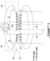
Fig. 2B presents a second embodiment of anigniter 22. In the embodiment presented inFig. 2B , the elements described above with respect toFig. 2A can all be present. For ease of reference, let us use cylindrical coordinates to define anaxial orientation 46 coinciding here with the tip of thefirst conductor 36. In addition to these elements, a circumferentially-oriented magnetic field B is provided at thespark path 44. When the electrons of the spark cross the gap between the positive terminal and the negative terminal, in a generally "radial" orientation, they individually have a charge q travelling at a velocity v across the magnetic field B. As per the Lorentz force equation
- For an equivalent effect in terms of ignition efficiency, this spark path curving effect may allow to retract the tip of the igniter from the combustion chamber to a somewhat lower temperature region, and thereby alleviate the thermally-imparted constraints on the design of the igniter and/or improve its durability.
- Such a circumferentially oriented magnetic field B may be generated by one or
more magnet 48 which are integrated to theigniter 22, and which may more specifically be embedded within theinsulator 42, radially between thefirst conductor 34 and thesecond conductor 38, and axially offset/retracted relative thetips magnets 48, which can be electromagnets, may have individual magnetic field axes extending between a north pole N and a south pole S, and these magnetic field axes can be oriented circumferentially, or tangentially, relative theaxis 46. - This force will now be explained in greater detail with reference with
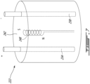
Fig. 3 . Taking the example of anelectromagnet 248 formed with a coil wrapped around a magnetic field axis. In accordance with the laws of electromagnetism, current circulating in the electric wire will generate a magnetic field circumferential to the length of the wire. In the context of a coil, the magnetic field generated by the different windings add up and generate a high magnetic field strength oriented along themagnetic field axis 252. A magnetic core (not shown for simplicity) may be provided within the winding, along themagnetic field axis 252, to both facilitate the wrapping of the coil and amplify the magnetic field strength. Depending on the circumferential direction, around the magnetic field axis, around which the coil is wrapped around the core, and the current direction along the wire, the magnetic field B will either exit one end of the coil or the other, defining a north pole N and a south pole P. In the example ofFig. 3 , the upper portion of the coil comes out from the page, the lower portion of the coil goes into the page, the positive terminal is at the left and the negative is at the right, leading to a north pole N on the right side and a south pole S on the right side. The magnetic field lines close back from the north pole N to the south pole S outside the core in a region of magnetic field strength which diminishes as the location is farther and farther away from thecoil 252. - Still referring to
Fig. 3 , afirst conductor 234 in the form of an elongated positive terminal or anode (+) and asecond conductor 238 in the form of an elongated negative terminal or cathode (-) are shown, with theelectromagnet 248 provided between the positive terminal and the negative terminal, and normal to both i) the orientation of the positive terminal or negative terminal, and ii) the electric field orientation extending between the negative terminal and the positive terminal. Upon travelling from the positive tip to the negative tip, the electrons will be subjected to an electric force qE driving their motion in the orientation qv between the positive tip and the negative tip. However, as perequation 1, the electrons, which represent charges in motion, will further be subjected to a magnetic force Fm. The amplitude and orientation of the magnetic force Fm will correspond to the vector cross product of the magnetic charge velocity qv and of the magnetic field orientation B at their instantaneous position. As per the "right hand rule" for a vector cross product, the resulting magnetic force Fm will be in the orientation away from the electromagnet, as per the arrow shown inFig. 3 . The resulting path which will be taken by the electrons will be the result of the combination between the electrical and magnetic forces and will curve away from the electromagnet before coming back at the negative terminal. If thecoil 248 was wound in the opposite direction, the north pole N and the south pole S would be inversed, and the resulting magnetic force would be in the orientation towards the electromagnet, which would not have the effect of "pushing" the spark deeper into the combustion chamber. - Referring back to the example presented in
Fig. 2B , extending this concept to a cylindrical geometry, the direction of the magnetic field B can be selected to be counter-clockwise (i.e. a counter-clockwise circumferential direction) around theaxis 46 when viewed in an axial direction from the spark path to the at least one magnet (i.e. looking at the tip of the igniter from the combustion chamber), to lead to pushing of the spark path deeper into the combustion chamber by the magnetic field, independently of which angle around theaxis 46 the spark actually takes as it travels from the positive terminal to the negative terminal. -
Fig. 4 presents an example schematic of anigniter subsystem 20 which may be associated to anigniter 22 such as shown inFig. 2B , except that in the simplified schematic ofFig. 4 , only twoelectromagnets 48, rather than four, are schematized. In this example, asingle voltage supply 60 is used to drive both theelectromagnets 48 and the sparks (positive terminal/negative terminal). A positive terminal of thevoltage source 60 can be connected to an exciter box orexciter 62, which leads to the positive terminal, and to avoltage regulator 64, which leads to a positive terminal of theelectromagnets 48. A negative terminal of theelectromagnets 48, of the voltage supply, and the negative terminal, may be grounded. Thevoltage regulator 64 can have the role of supplying a controlled, moderate, voltage across theelectromagnets 48 in a manner, for instance, to generate a relatively stable magnetic field of an appropriate strength for pushing the spark into the combustion chamber by an appropriate amount. Theexciter 62 can have the role of accumulating a very high voltage and to then discharge a strong current as a spark. Either one, or more than one of thevoltage regulator 64,exciter 62 andvoltage supply 60 may be controlled by acontroller 400. - The components of the
igniter subsystem 20 such as thevoltage supply 60 and exciter may be included as part of a body of the igniter itself, such as aportion 32 of theigniter 22 which is maintained away from the highest temperature regions of thecombustion chamber 26 throughout operation, in which case a single electrical connection may be used as thevoltage supply 60. In an alternate embodiment, the voltage supply and exciter may be embodied as part of a component which is distinct from the igniter, and electrically connected thereto. In still a further alternate embodiment, the voltage regulator and/or the exciter may be omitted or substituted by one or more other suitable components. In an alternate embodiment, the voltage regulator and the exciter can be connectable via distinct electrical terminals. - Referring back to the embodiment presented in
Fig. 2B , it will be understood that in alternate embodiments, a different number ofmagnets 48 may be used. For instance, there may be 6 magnets, 8 magnets, or still a different number ofmagnets 48. The magnets may be circumferentially aligned with one another, with the north poles all pointing clockwise (having a clockwise circumferential direction) and the south poles all pointing counter-clockwise (having a counter-clockwise circumferential direction) when viewed from the combustion chamber. - It will be noted here that in practice, since the magnets of the plurality of circumferentially interspaced magnets are discrete in the illustrated embodiment, the overall magnetic field, while still generally having a "counter-clockwise" direction when taking the individual magnets collectively, will be irregular and in particular, will have regions of significantly weaker magnetic field, interspersed circumferentially with the magnets. More specifically, represented schematically here by dashed-line cylinders, regions of weaker
magnetic field 49 will be present circumferentially at circumferential positions corresponding to gaps between corresponding adjacent pairs ofmagnets 48. Referring back toFig. 3 , these regions of weakermagnetic field 249 are associated with corresponding ends of the magnets, where the magnetic field lines close back towards the core rather than extending parallel to the core. - Referring back to a cylindrical geometry such as shown in
Fig. 2B , it will be understood that while a spark travelling above either one of themagnets 48 may be suitably deflected outwardly by the magnetic field, a spark travelling across either one of the regions of weakermagnetic field 49 may be less suitably deflected outwardly given the weaker or differently oriented magnetic field. It may be preferred to impede sparks from forming in the regions of weakermagnetic field 49.Figs. 5A and 5B present two example ways of addressing this. - In the embodiment presented in
Fig. 5A , theannular tip 340 of the second conductor has a plurality of insulatingcaps 349. The insulatingcaps 349 are located circumferentially between corresponding pairs of themagnets 348, at an axial position of the spark path, and are configured to prevent a spark from extending across a region of weakermagnetic field 49. Accordingly, the plurality of insulatingcaps 349 constitute a plurality of insulator elements, each insulator element located circumferentially between a corresponding pair ofmagnets 348 of the plurality of magnets, and intersecting the spark path. - In the embodiment presented in
Fig. 5B , theinsulator 342 itself is provided with an irregular shape. More specifically, the tip of theinsulator 342 is crenellated, and has a plurality of crenels protruding axially, between theannular tip 340 of the second conductor and thecentral tip 346 of the first conductor. The crenels are located circumferentially between corresponding pairs of themagnets 348, at an axial position of the spark path, and are configured to prevent a spark from extending across a region of weaker magnetic field. Accordingly, the protruding crenels constitute a plurality of insulator elements, each insulator element located circumferentially between a corresponding pair ofmagnets 348 of the plurality of magnets, and intersecting the spark path. -
Fig. 6 presents a second variant to the embodiment ofFig. 2B . In the embodiment ofFig. 6 ,permanent magnets 448, more specifically four straight bar magnets having lengthwisely opposite poles, are used instead of theelectromagnets 48 which are illustrated in the embodiment ofFig. 2B . Similarly to theelectromagnets 48 which are illustrated in the embodiment ofFig. 2B , the permanent magnets are interspaced from one another in the circumferential orientation. Thepermanent magnets 448 have south poles oriented counter-clockwise relative the axis when viewed from the combustion chamber. Accordingly, a magnet may be either a permanent magnet or an electromagnet. In some embodiments, permanent magnet material may be suitable. In other embodiments, permanent magnet material may be deemed too sensitive to heat and not be suitable, particularly in the context where the igniters are associated to the combustion chamber of gas turbine engines. This being said, permanent magnets embedded in a suitable insulator material may nonetheless be suitable to some embodiments. -
Fig. 7 presents yet another embodiment of anigniter 222. In the embodiment presented inFig. 7 , thefirst conductor 234 and thesecond conductor 238 both lead to tips in the form of pins which protrude from theinsulator 242. Anelectromagnet 248 is embedded in theinsulator 242, between the pins. The magnetic field generated by the electromagnet can have the effect of curving the spark path away from the electromagnet, deeper into the combustion chamber, such as schematized inFig. 3 . The spark path extends from the positive terminal (+) to the negative terminal (-) and the north pole can be oriented towards the right hand side from the perspective of moving along the spark path. - Referring to
Fig. 8 , it will be understood that the expression "computer" 400 as used herein is not to be interpreted in a limiting manner. It is rather used in a broad sense to generally refer to the combination of some form of one ormore processing units 412 and some form ofmemory system 414 accessible by the processing unit(s). The memory system can be of the non-transitory type. The use of the expression "computer" in its singular form as used herein includes within its scope one or more processing units working to perform a given function. - A processing unit can be embodied in the form of a general-purpose microprocessor or microcontroller, a digital signal processing (DSP) processor, an integrated circuit, a field programmable gate array (FPGA), a reconfigurable processor, a programmable read-only memory (PROM), an electronic engine controller EEC, a full authority digital engine controller (FADEC), to name a few examples.
- The memory system can include a suitable combination of any suitable type of computer-readable memory located either internally, externally, and accessible by the processor in a wired or wireless manner, either directly or over a network such as the Internet. A computer-readable memory can be embodied in the form of random-access memory (RAM), read-only memory (ROM), compact disc read-only memory (CDROM), electro-optical memory, magneto-optical memory, erasable programmable read-only memory (EPROM), and electrically-erasable programmable read-only memory (EEPROM), Ferroelectric RAM (FRAM)to name a few examples.
- A computer can have one or more input/output (I/O) interface to allow communication with a human user and/or with another computer via an associated input, output, or input/output device such as a keyboard, a mouse, a touchscreen, an antenna, a port, etc. Each I/O interface can enable the computer to communicate and/or exchange data with other components, to access and connect to network resources, to serve applications, and/or perform other computing applications by connecting to a network (or multiple networks) capable of carrying data including the Internet, Ethernet, plain old telephone service (POTS) line, public switch telephone network (PSTN), integrated services digital network (ISDN), digital subscriber line (DSL), coaxial cable, fiber optics, satellite, mobile, wireless (e.g. Wi-Fi, Bluetooth, WiMAX), SS7 signaling network, fixed line, local area network, wide area network, to name a few examples.
- It will be understood that a computer can perform functions or processes via hardware or a combination of both hardware and software. For example, hardware can include logic gates included as part of a silicon chip of a processor. Software (e.g. application, process) can be in the form of data such as computer-readable instructions stored in a non-transitory computer-readable memory accessible by one or more processing units. With respect to a computer or a processing unit, the expression "configured to" relates to the presence of hardware or a combination of hardware and software which is operable to perform the associated functions. In the context of this specification, a computer or controller can be implemented in a cloud based, or virtual-machine based manner via software applications.
- The embodiments described in this document provide non-limiting examples of possible implementations of the present technology. Upon review of the present disclosure, a person of ordinary skill in the art will recognize that changes may be made to the embodiments described herein without departing from the scope of the present technology. For example, in still a further embodiment, the magnetic field may be induced by arc current directed through a small number of turns, where the arc's fast di/dt may induce a strong magnetic field. Yet further modifications could be implemented by a person of ordinary skill in the art in view of the present disclosure, which modifications would be within the scope of the present technology.
Claims (15)
- An igniter (22; 122; 222) comprising:a first conductor (34; 134; 234) having a tip (36; 136) extending along an axis (46) and forming a positive terminal;a second conductor (38; 138; 238) having a tip (40; 140) surrounding the tip (36; 136) of the first conductor (34; 134; 234) around the axis (46) and forming a negative terminal;an insulator (42; 142; 242; 342) filling a space between the first conductor (34; 134; 234) and the second conductor (38; 138; 238), with the tip (36; 136) of the first conductor (34; 134; 234) and the tip (40; 140) of the second conductor (38; 138; 238) protruding from the insulator (42; ...; 342);a spark path (44; 144) extending radially, relative the axis (46), between the tip (36; 136) of the first conductor (34; 134; 234) and the tip (40; 140) of the second conductor (38; 138; 238), from the positive terminal to the negative terminal; andat least one magnet (48) operable to generate a magnetic field (B), the magnetic field (B) having a magnetic field orientation extending circumferentially around the axis (46), the at least one magnet (48) disposed radially, relative the axis (46), between the first conductor (34; 134; 234) and the second conductor (38; 138; 238), the at least one magnet (48) embedded within the insulator (42; ...; 342).
- The igniter (22; 122; 222) of claim 1 wherein the at least one magnet (48) includes a plurality of magnets (48) interspaced from one another circumferentially relative the axis (46), each magnet (48) of the plurality of magnets (48) having a length extending tangentially relative the axis (46), a north pole oriented clockwise relative the axis (46), and a south pole oriented counter-clockwise relative the axis (46) when viewed in an axial direction extending from the spark path (44; 144) towards the at least one magnet (48).
- The igniter (22; 122; 222) of claim 2 further comprising a plurality of insulator elements (349), each insulator element (349) located circumferentially between a corresponding pair of magnets (348) of the plurality of magnets (348), and intersecting the spark path (44; 144).
- The igniter (22; 122; 222) of any preceding claim wherein the at least one magnet (48) is at least one electromagnet (248).
- The igniter (22; 122; 222) of any of claims 1 to 3 wherein the at least one magnet (48) is at least one permanent magnet (48).
- The igniter (22; 122; 222) of any preceding claim wherein a portion of the magnetic field B extending at the spark path (44; 144) has a counter-clockwise direction relative the axis (46) when viewed in an axial direction extending from the spark path (44; 144) towards the at least one magnet (48).
- A gas turbine engine (10) comprising:in serial flow communication a compressor section (14), a combustor (16), and a turbine section (18); andan ignition subsystem (20) having at least one igniter (22; 122; 222), the at least one igniter (22; 122; 222) being the igniter of any of claims 1 to 5, wherein:the tip (36; 136) of the first conductor (34; 134; 234) is exposed to a combustion chamber (26) in the combustor (16); andthe tip (40; 140) of the second conductor (38; 138; 238) is exposed to a combustion chamber (26) in the combustor (16).
- The gas turbine engine (10) of claim 7, wherein a portion of the magnetic field B extending at the spark path (44; 144) has a counter-clockwise direction relative the axis (46) when viewed from the combustion chamber (26).
- The gas turbine engine (10) of claim 7 or 8, wherein the ignition subsystem (20) further comprises:at least one voltage source (60), a voltage regulator (64) connected between the at least one voltage source (60) and the first conductor (34; 134; 234); andan exciter (62) connected between the at least one voltage source (60) and the positive terminal.
- The gas turbine engine (10) of claim 9, wherein the voltage regulator (64) and the exciter (62) are integrated to a body of the igniter (22; 122; 222).
- The gas turbine engine (10) of claim 9 or 10, wherein the at least one voltage source (60) is a single voltage source (60) having a positive terminal connected to both the voltage regulator (64) and the exciter (62).
- The gas turbine engine (10) of any of claims 7 to 11, wherein the second conductor (38; 138; 238) and the negative terminal are grounded.
- An igniter (22; 122; 222) comprising:a first conductor (34; 134; 234) extending along a length of the igniter (22; 122; 222);a second conductor (38; 138; 238) extending alongside and spaced apart from the first conductor (34; 134; 234);an insulator (42; ...; 342) filling a space between a portion of the first conductor (34; 134; 234) and a portion of the second conductor (38; 138; 238), with a tip (36; 136) of the first conductor (34; 134; 234) protruding from the insulator (42; ...; 342) and forming a positive terminal, and a tip (40; 140) of the second conductor (38; 138; 238) positioned adjacent the tip (36; 136) of the first conductor (34; 134; 234) and forming a negative terminal;a spark path (44; 144) extending from the positive terminal to the negative terminal; andan electromagnet (248) embedded within the insulator (42; ...; 342), between the first conductor (34; 134; 234) and the second conductor (38; 138; 238), and having a magnetic field axis (252) extending from a north pole to a south pole, the magnetic field axis (252) extending transversally relative the spark path (44; 144).
- The igniter (22; 122; 222) of claim 13, wherein:the north pole is oriented towards a right hand side relative a direction of the spark path (44; 144); and/orthe second conductor (38; 138; 238) and the negative terminal are grounded.
- The igniter (22; 122; 222) of claim 13 or 14 further comprising:at least one voltage source (60), a voltage regulator (64) connected between the at least one voltage source (60) and the first conductor (34; 134; 234); andan exciter (62) connected between the at least one voltage source (60) and the positive terminal.
Applications Claiming Priority (1)
| Application Number | Priority Date | Filing Date | Title |
|---|---|---|---|
| US18/191,181 US12237649B2 (en) | 2023-03-28 | 2023-03-28 | Spark igniter with magnetic field for pushing spark |
Publications (1)
| Publication Number | Publication Date |
|---|---|
| EP4438877A1 true EP4438877A1 (en) | 2024-10-02 |
Family
ID=90571875
Family Applications (1)
| Application Number | Title | Priority Date | Filing Date |
|---|---|---|---|
| EP24167657.6A Pending EP4438877A1 (en) | 2023-03-28 | 2024-03-28 | Igniter for a gas turbine |
Country Status (3)
| Country | Link |
|---|---|
| US (1) | US12237649B2 (en) |
| EP (1) | EP4438877A1 (en) |
| CA (1) | CA3232860A1 (en) |
Citations (5)
| Publication number | Priority date | Publication date | Assignee | Title |
|---|---|---|---|---|
| US2635423A (en) * | 1950-08-28 | 1953-04-21 | Edward J Oakes | Igniter for internal-combustion engines |
| GB1146244A (en) * | 1967-01-25 | 1969-03-19 | Rolls Royce | Spark igniter |
| DE19607654A1 (en) * | 1995-08-16 | 1997-09-04 | Siegfried Schwarz | Spark plug ignition of air=fuel mixture |
| JP2001076841A (en) * | 1999-09-02 | 2001-03-23 | Nippon Soken Inc | Ignitor for internal combustion engine |
| JP2010203295A (en) * | 2009-03-02 | 2010-09-16 | Toyota Motor Corp | Plasma ignition device |
Family Cites Families (7)
| Publication number | Priority date | Publication date | Assignee | Title |
|---|---|---|---|---|
| US5587630A (en) * | 1993-10-28 | 1996-12-24 | Pratt & Whitney Canada Inc. | Continuous plasma ignition system |
| US5555862A (en) * | 1994-07-19 | 1996-09-17 | Cummins Engine Company, Inc. | Spark plug including magnetic field producing means for generating a variable length arc |
| US5619959A (en) | 1994-07-19 | 1997-04-15 | Cummins Engine Company, Inc. | Spark plug including magnetic field producing means for generating a variable length arc |
| US6929727B2 (en) | 1999-04-12 | 2005-08-16 | G & H Technologies, Llc | Rectangular cathodic arc source and method of steering an arc spot |
| US6568362B2 (en) * | 2001-06-12 | 2003-05-27 | Ut-Battelle, Llc | Rotating arc spark plug |
| WO2022229774A1 (en) | 2021-04-28 | 2022-11-03 | King Abdullah University Of Science And Technology | Floating spark plug and ignition method for internal combustion engine |
| WO2022229803A1 (en) | 2021-04-28 | 2022-11-03 | King Abdullah University Of Science And Technology | Magnetically boosted spark plug, ignition system and method |
-
2023
- 2023-03-28 US US18/191,181 patent/US12237649B2/en active Active
-
2024
- 2024-03-21 CA CA3232860A patent/CA3232860A1/en active Pending
- 2024-03-28 EP EP24167657.6A patent/EP4438877A1/en active Pending
Patent Citations (5)
| Publication number | Priority date | Publication date | Assignee | Title |
|---|---|---|---|---|
| US2635423A (en) * | 1950-08-28 | 1953-04-21 | Edward J Oakes | Igniter for internal-combustion engines |
| GB1146244A (en) * | 1967-01-25 | 1969-03-19 | Rolls Royce | Spark igniter |
| DE19607654A1 (en) * | 1995-08-16 | 1997-09-04 | Siegfried Schwarz | Spark plug ignition of air=fuel mixture |
| JP2001076841A (en) * | 1999-09-02 | 2001-03-23 | Nippon Soken Inc | Ignitor for internal combustion engine |
| JP2010203295A (en) * | 2009-03-02 | 2010-09-16 | Toyota Motor Corp | Plasma ignition device |
Also Published As
| Publication number | Publication date |
|---|---|
| CA3232860A1 (en) | 2025-06-23 |
| US12237649B2 (en) | 2025-02-25 |
| US20240332915A1 (en) | 2024-10-03 |
Similar Documents
| Publication | Publication Date | Title |
|---|---|---|
| CN104595087B (en) | Pass through the igniter of the fuel air mixture in corona discharge ignition engine | |
| CN203515920U (en) | Multi-coil spark ignition system | |
| CN101057379B (en) | RF plasma spark plug | |
| JP6616081B2 (en) | Ignition exciter discharge switch | |
| US9581118B2 (en) | Injector-igniters with variable gap electrode | |
| JP2018060797A (en) | Corona igniter having temperature control function | |
| EP3196444B1 (en) | Solid state spark device | |
| US12237649B2 (en) | Spark igniter with magnetic field for pushing spark | |
| US7768767B2 (en) | Triggered pulsed ignition system and method | |
| US2590778A (en) | Dual plug ignition system | |
| US10177538B2 (en) | Ignition unit for an internal combustion engine | |
| CN102804527B (en) | Spark plug, ignition system, engine and ignition method for the engine | |
| US2662202A (en) | Ignition system | |
| CN109312707A (en) | Ignition device for igniting air/fuel mixture in combustion chamber | |
| KR101749685B1 (en) | spark plug | |
| USRE32505E (en) | Combustion initiation system | |
| KR101507092B1 (en) | Magnetic Induction Coil Mounted Spark Plug | |
| JP4635765B2 (en) | Ignition device for internal combustion engine | |
| JP3218967U (en) | Connected spark discharge ignition device | |
| RU2268395C1 (en) | Ignition system for internal combustion engine | |
| KR101398854B1 (en) | Low current circuit for corona discharge ignition and corona discharge igniting system having the same | |
| RU2127936C1 (en) | Device for igniting and burning fuel mixture in internal-combustion engines | |
| RU2149488C1 (en) | Lightning surge protective device for overhead power transmission lines | |
| RU2216063C2 (en) | Ignition coil | |
| JPS6123635B2 (en) |
Legal Events
| Date | Code | Title | Description |
|---|---|---|---|
| PUAI | Public reference made under article 153(3) epc to a published international application that has entered the european phase |
Free format text: ORIGINAL CODE: 0009012 |
|
| STAA | Information on the status of an ep patent application or granted ep patent |
Free format text: STATUS: THE APPLICATION HAS BEEN PUBLISHED |
|
| AK | Designated contracting states |
Kind code of ref document: A1 Designated state(s): AL AT BE BG CH CY CZ DE DK EE ES FI FR GB GR HR HU IE IS IT LI LT LU LV MC ME MK MT NL NO PL PT RO RS SE SI SK SM TR |
|
| STAA | Information on the status of an ep patent application or granted ep patent |
Free format text: STATUS: REQUEST FOR EXAMINATION WAS MADE |
|
| 17P | Request for examination filed |
Effective date: 20250402 |