EP4438860A1 - Extraction steam turbine with grid valve - Google Patents
Extraction steam turbine with grid valve Download PDFInfo
- Publication number
- EP4438860A1 EP4438860A1 EP23165331.2A EP23165331A EP4438860A1 EP 4438860 A1 EP4438860 A1 EP 4438860A1 EP 23165331 A EP23165331 A EP 23165331A EP 4438860 A1 EP4438860 A1 EP 4438860A1
- Authority
- EP
- European Patent Office
- Prior art keywords
- grid valve
- openings
- steam
- disk
- pockets
- Prior art date
- Legal status (The legal status is an assumption and is not a legal conclusion. Google has not performed a legal analysis and makes no representation as to the accuracy of the status listed.)
- Pending
Links
Images

Classifications
-
- F—MECHANICAL ENGINEERING; LIGHTING; HEATING; WEAPONS; BLASTING
- F01—MACHINES OR ENGINES IN GENERAL; ENGINE PLANTS IN GENERAL; STEAM ENGINES
- F01D—NON-POSITIVE DISPLACEMENT MACHINES OR ENGINES, e.g. STEAM TURBINES
- F01D17/00—Regulating or controlling by varying flow
- F01D17/10—Final actuators
- F01D17/12—Final actuators arranged in stator parts
- F01D17/14—Final actuators arranged in stator parts varying effective cross-sectional area of nozzles or guide conduits
- F01D17/141—Final actuators arranged in stator parts varying effective cross-sectional area of nozzles or guide conduits by means of shiftable members or valves obturating part of the flow path
-
- F—MECHANICAL ENGINEERING; LIGHTING; HEATING; WEAPONS; BLASTING
- F01—MACHINES OR ENGINES IN GENERAL; ENGINE PLANTS IN GENERAL; STEAM ENGINES
- F01D—NON-POSITIVE DISPLACEMENT MACHINES OR ENGINES, e.g. STEAM TURBINES
- F01D17/00—Regulating or controlling by varying flow
- F01D17/10—Final actuators
- F01D17/12—Final actuators arranged in stator parts
- F01D17/14—Final actuators arranged in stator parts varying effective cross-sectional area of nozzles or guide conduits
- F01D17/141—Final actuators arranged in stator parts varying effective cross-sectional area of nozzles or guide conduits by means of shiftable members or valves obturating part of the flow path
- F01D17/145—Final actuators arranged in stator parts varying effective cross-sectional area of nozzles or guide conduits by means of shiftable members or valves obturating part of the flow path by means of valves, e.g. for steam turbines
-
- F—MECHANICAL ENGINEERING; LIGHTING; HEATING; WEAPONS; BLASTING
- F16—ENGINEERING ELEMENTS AND UNITS; GENERAL MEASURES FOR PRODUCING AND MAINTAINING EFFECTIVE FUNCTIONING OF MACHINES OR INSTALLATIONS; THERMAL INSULATION IN GENERAL
- F16K—VALVES; TAPS; COCKS; ACTUATING-FLOATS; DEVICES FOR VENTING OR AERATING
- F16K3/00—Gate valves or sliding valves, i.e. cut-off apparatus with closing members having a sliding movement along the seat for opening and closing
- F16K3/02—Gate valves or sliding valves, i.e. cut-off apparatus with closing members having a sliding movement along the seat for opening and closing with flat sealing faces; Packings therefor
- F16K3/04—Gate valves or sliding valves, i.e. cut-off apparatus with closing members having a sliding movement along the seat for opening and closing with flat sealing faces; Packings therefor with pivoted closure members
- F16K3/06—Gate valves or sliding valves, i.e. cut-off apparatus with closing members having a sliding movement along the seat for opening and closing with flat sealing faces; Packings therefor with pivoted closure members in the form of closure plates arranged between supply and discharge passages
- F16K3/08—Gate valves or sliding valves, i.e. cut-off apparatus with closing members having a sliding movement along the seat for opening and closing with flat sealing faces; Packings therefor with pivoted closure members in the form of closure plates arranged between supply and discharge passages with circular plates rotatable around their centres
-
- F—MECHANICAL ENGINEERING; LIGHTING; HEATING; WEAPONS; BLASTING
- F16—ENGINEERING ELEMENTS AND UNITS; GENERAL MEASURES FOR PRODUCING AND MAINTAINING EFFECTIVE FUNCTIONING OF MACHINES OR INSTALLATIONS; THERMAL INSULATION IN GENERAL
- F16K—VALVES; TAPS; COCKS; ACTUATING-FLOATS; DEVICES FOR VENTING OR AERATING
- F16K47/00—Means in valves for absorbing fluid energy
- F16K47/04—Means in valves for absorbing fluid energy for decreasing pressure or noise level, the throttle being incorporated in the closure member
- F16K47/045—Means in valves for absorbing fluid energy for decreasing pressure or noise level, the throttle being incorporated in the closure member and the closure member being rotatable
-
- F—MECHANICAL ENGINEERING; LIGHTING; HEATING; WEAPONS; BLASTING
- F16—ENGINEERING ELEMENTS AND UNITS; GENERAL MEASURES FOR PRODUCING AND MAINTAINING EFFECTIVE FUNCTIONING OF MACHINES OR INSTALLATIONS; THERMAL INSULATION IN GENERAL
- F16K—VALVES; TAPS; COCKS; ACTUATING-FLOATS; DEVICES FOR VENTING OR AERATING
- F16K47/00—Means in valves for absorbing fluid energy
- F16K47/08—Means in valves for absorbing fluid energy for decreasing pressure or noise level and having a throttling member separate from the closure member, e.g. screens, slots, labyrinths
-
- F—MECHANICAL ENGINEERING; LIGHTING; HEATING; WEAPONS; BLASTING
- F05—INDEXING SCHEMES RELATING TO ENGINES OR PUMPS IN VARIOUS SUBCLASSES OF CLASSES F01-F04
- F05D—INDEXING SCHEME FOR ASPECTS RELATING TO NON-POSITIVE-DISPLACEMENT MACHINES OR ENGINES, GAS-TURBINES OR JET-PROPULSION PLANTS
- F05D2220/00—Application
- F05D2220/30—Application in turbines
- F05D2220/31—Application in turbines in steam turbines
Definitions
- steam is required to extract from the steam turbine to utilize it in the process of manufacturing products.
- Steam is taken out from the opening in the casing of the extraction steam turbine at controlled pressure (as per customer requirement). This steam is used in the process.
- the required portion of the steam is extracted, and the remaining steam moves forward in the remaining part of the extraction steam turbine (LP -low-pressure part) to produce power.
- the extraction steam turbine is also operated at part-load other than design load (mass flow rate at the entry of the turbine for which turbine flow path is designed for optimum thermal efficiency). i.e., the mass flow rate at the entry is less and/or more steam is extracted (referred to as part load).
- an extraction valve is used.
- the objective of the invention is to improve the efficiency of the extraction steam turbine used in the process industries by modifying the extraction valve design, especially in part load mode.
- the inventive extraction steam turbine comprising a grid valve for controlling a steam throughput, wherein the grid valve is mounted behind an extraction zone which is located between a high-pressure stage and a low-pressure stage, wherein the high-pressure stage is fixed at a first guide blade carriers and the low-pressure stage is fixed at a second guide blade carriers, wherein the grid valve consists of a rotatable disk and a stationary disk and is fixed at the second guide blade carrier, wherein the rotatable disk and the stationary disk have several pockets which are distribute on an inner circular and which can be brought, by rotating the rotatable disk, to overlap and builds first openings which guide the steam into rotor blades which are next downstream the grid valve, is characterized in that the rotatable disk and the stationary disk have several further pockets which are distribute on an outer circular and which can be brought, by rotating the rotatable disk, to overlap and builds second openings which guide the steam through openings which are create with the same patter as the pockets in the grid valve, whereby the openings are part of a bypass
- the steam energy losses in the grid valve can reduced significate. This is due to better guidance of the flow through pockets in the grid valve and further through GBC and/or blade group.
- the flow passing through inner pockets and going into rotor blade which is next to pockets is called RK bypass arrangement and the flow going through GBC passages bypassing blade group which is next to pockets is called Inner bypass.
- the pocket area is calculated based on the mass flow rate of the steam passing through it.
- the grid valve is either in RK bypass condition or in fully open condition (RK bypass and Inner bypass).
- Grid valve (LP control valve - two-channel flow) with RK bypass and Inner bypass improves the thermal efficiency of the steam turbine at part load. It also employs simple cost-saving mechanical construction. It can be highly beneficial for extraction steam turbines used in the process industries.
- Grid valve employs simple window design with the two-channel flow - mechanical design. This design of the product enables the extraction steam turbine to utilize steam energy (enthalpy) more efficiently compared to the profile design of the valve at part loads. Hence it significantly improves thermal efficiencies resulting in lower specific steam consumption for the required power output at part loads.
- An advantageous embodiment of the invention provides that the patter of the pockets is designed in such a matter that depending on the position of the rotatable disk related to the stationary disk, at the minimum, three opening positions are available, wherein in a first position, the grid valve is fully closed, in a second position, the RK Bypass is open, and the Inner Bypass is closed, and in the third position RK Bypass and Inner Bypass open.
- This arrangement makes the extraction steam turbine more efficient at part loads compared to the existing available solutions in the market. It can be seen as a more economical and efficient solution for extraction steam turbines in the current competitive market.
- Fig. 1 shows a general view of the extraction steam turbine 1 with extraction valve 2.
- the extraction steam turbine 1 exists of a turbine casing 18 and at the minimum two stages, a high-pressure stage 4 and a low-pressure stage 5., wherein the high-pressure stage 4 is fixed at a first guide blade carriers 6 and the low-pressure stage 5 is fixed at a second guide blade carriers 7.
- the live steam entry the turbine casing 18, via the steam entry 19.
- steam is required with preset steam parameters. This steam, with is taken out from the extraction opening 20 at controlled pressure and is used in the industrial process.
- the remaining steam moves forward in the remaining part of the turbine (LP -low-pressure part) to produce electrical energy via a generator G and leave the extraction steam turbine 1 by the steam exit 21.
- the extraction of the steam takes place within an extraction zone 3 by use of the grid valve 2, which is mounted at the second guide blade carrier 7.
- the grid valve 2 employs simple window design with the two-channel flow - mechanical design. This new design enables the extraction steam turbine 1 to utilize steam energy (enthalpy) more efficiently compared to the profile design of the valve at part loads. Hence it significantly improves thermal efficiencies resulting in lower specific steam consumption for the required power output at part loads.
- Fig. 2 shows a sectional view of an inventive extraction steam turbine 1.
- the extraction steam turbine 1 has a grid valve 2 which consists of two disks, a rotatable front disk 8 and a stationary rear disk 9.
- Both disks 8, 9, have several pockets which are created in the disks 8, 9 in a circular pattern, wherein inner pockets 10 are located on an inner circular 11 and outer pockets 14, are located on an outer circular 15.
- inner pockets 10 are located on an inner circular 11 and outer pockets 14, are located on an outer circular 15.
- the outer pockets 14 builds second openings 16 which guide the steam through third openings 17, which are part of cannels 18 in the second guide blade carrier 7, bypassing the rotor blades 13 which are next downstream the grid valve 2.
- the third openings 17 are in a circular pattern having a pitch distance equal to outer pockets 14.
- the flow passing through inner pockets 10 and going into rotor blade which is next to pockets is called RK bypass.
- Arrangement and the flow going through GBC passages bypassing blade group which is next to pockets is called Inner bypass.
- the pocket area is calculated based on the mass flow rate of the steam passing through it.
- the grid valve 2 is either in RK bypass condition or in fully open condition (RK bypass and Inner bypass).
- Figure 4 shows such kinds of arrangements.
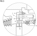
- Fig. 3 shows a more detail view of the example in Fig. 2 in axial section.
- the inner bypass and the RK bypass are open, so that the steam flows partly to the RK bypass and from there to the rotor blades 13 which are next downstream the grid valve 2 and partly to the inner bypass so that this steam bypassing the rotor blades 13 which are next downstream the grid valve 2.
- the stationary rear disk 9 is fastened to the second guide blade carriers 7 with screws 22.
- roller bearings 23 are placed between the disks 8, 9.
- the rotatable front disk position is regulated by a non-shown servo motor.
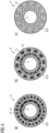
- Fig. 4 a-c shows three different switching positions of the grid valve 2.
- the inner and the outer pockets 11, 14 in in the stationary rear disk 9 are covered by the rotatable front disk 8, so that the inner bypass and the RK bypass are closed.
- a grid valve with a two-channel flow design is mounted on GBC which is next to the extraction point.
- the pocket design enables it to control the mass flow rate through pocket openings which helps in extracting the steam at the required pressure as well as channeling the flow further in the LP part (the part after extraction) of the turbine.
- This arrangement makes the turbine more efficient at part loads compared to the existing available solutions in the market. It can be seen as a more economical and efficient solution for extraction turbines in the current competitive market.
Landscapes
- Engineering & Computer Science (AREA)
- General Engineering & Computer Science (AREA)
- Mechanical Engineering (AREA)
- Control Of Turbines (AREA)
Abstract
Description
- In process industries like paper, sugar, pulp, chemical, etc., steam is required to extract from the steam turbine to utilize it in the process of manufacturing products. i.e. Steam is taken out from the opening in the casing of the extraction steam turbine at controlled pressure (as per customer requirement). This steam is used in the process. At the extraction point in the intermediate portion of the extraction steam turbine, the required portion of the steam is extracted, and the remaining steam moves forward in the remaining part of the extraction steam turbine (LP -low-pressure part) to produce power.
- Depending upon the power and steam requirement for the process, the extraction steam turbine is also operated at part-load other than design load (mass flow rate at the entry of the turbine for which turbine flow path is designed for optimum thermal efficiency). i.e., the mass flow rate at the entry is less and/or more steam is extracted (referred to as part load).
- To control the extraction process and regulate the steam flow in the extraction steam turbine, an extraction valve is used.
- There are several types of extraction valve arrangements available to extract steam at the required pressure. Depending upon the mechanical design, they play important role in the thermal efficiency of the turbine at part loads. The most widely used arrangements are as follows:
- 1. Adaptive stage: Flow passes through aerofoiled vanes. Mass flow rate is controlled by a rotating disk. Vane opening is adjusted by rotation.
- 2. Grid valve: Flow passes through pockets in a disk. Mass flow rate is controlled by a rotating disk. Pocket opening is adjusted by rotation.
- 3. Nozzle group control: This arrangement controls mass flow rate through nozzles.
- 4. Internal valve: This arrangement controls the mass flow rate through the stem.
- 5. External valve: This arrangement controls the mass flow rate through the stem.
- All current solutions have the disadvantage of low efficiency in part load mode.
- The objective of the invention is to improve the efficiency of the extraction steam turbine used in the process industries by modifying the extraction valve design, especially in part load mode.
- The objective of the invention is solved by the features of claim 1. Advantageous embodiments of the invention, which can be used individually or in combination with each other, are subject of the subclaim.
- The inventive extraction steam turbine, comprising a grid valve for controlling a steam throughput, wherein the grid valve is mounted behind an extraction zone which is located between a high-pressure stage and a low-pressure stage, wherein the high-pressure stage is fixed at a first guide blade carriers and the low-pressure stage is fixed at a second guide blade carriers, wherein the grid valve consists of a rotatable disk and a stationary disk and is fixed at the second guide blade carrier, wherein the rotatable disk and the stationary disk have several pockets which are distribute on an inner circular and which can be brought, by rotating the rotatable disk, to overlap and builds first openings which guide the steam into rotor blades which are next downstream the grid valve, is characterized in that the rotatable disk and the stationary disk have several further pockets which are distribute on an outer circular and which can be brought, by rotating the rotatable disk, to overlap and builds second openings which guide the steam through openings which are create with the same patter as the pockets in the grid valve, whereby the openings are part of a bypass in the second guide blade carrier, bypassing the rotor blades which are next downstream the grid valve.
- By changing the mechanical design in the grid valve as well as in Guide Blade Carrier (GBC), on which the grid valve is attached, the steam energy losses in the grid valve can reduced significate. This is due to better guidance of the flow through pockets in the grid valve and further through GBC and/or blade group. The flow passing through inner pockets and going into rotor blade which is next to pockets is called RK bypass arrangement and the flow going through GBC passages bypassing blade group which is next to pockets is called Inner bypass. The pocket area is calculated based on the mass flow rate of the steam passing through it. Depending upon power requirement, the grid valve is either in RK bypass condition or in fully open condition (RK bypass and Inner bypass).
- Grid valve (LP control valve - two-channel flow) with RK bypass and Inner bypass improves the thermal efficiency of the steam turbine at part load. It also employs simple cost-saving mechanical construction. It can be highly beneficial for extraction steam turbines used in the process industries.
- Grid valve employs simple window design with the two-channel flow - mechanical design. This design of the product enables the extraction steam turbine to utilize steam energy (enthalpy) more efficiently compared to the profile design of the valve at part loads. Hence it significantly improves thermal efficiencies resulting in lower specific steam consumption for the required power output at part loads.
- An advantageous embodiment of the invention provides that the patter of the pockets is designed in such a matter that depending on the position of the rotatable disk related to the stationary disk, at the minimum, three opening positions are available, wherein in a first position, the grid valve is fully closed, in a second position, the RK Bypass is open, and the Inner Bypass is closed, and in the third position RK Bypass and Inner Bypass open. This arrangement makes the extraction steam turbine more efficient at part loads compared to the existing available solutions in the market. It can be seen as a more economical and efficient solution for extraction steam turbines in the current competitive market.
- The invention is explained below with reference to examples of embodiments. It shows:
-
Fig. 1 : A general view of the extraction steam turbine with extraction valve used in the process industries -
Fig. 2 : An example of an inventive grid valve and GBC (Sectional View) -
Fig. 3 : A more detail view of the example inFig. 2 in axial section -
Fig. 4 a-c : Different open positions of the grid valve shown inFig. 2 and3 . - All figures show only simplified illustrations of the invention that are not true to scale. Identical or functionally identical components are provided with the same reference numbers across all figures.
-
Fig. 1 shows a general view of the extraction steam turbine 1 withextraction valve 2. The extraction steam turbine 1 exists of aturbine casing 18 and at the minimum two stages, a high-pressure stage 4 and a low-pressure stage 5., wherein the high-pressure stage 4 is fixed at a firstguide blade carriers 6 and the low-pressure stage 5 is fixed at a secondguide blade carriers 7. During the operation mode, the live steam entry theturbine casing 18, via thesteam entry 19. In process industries, steam is required with preset steam parameters. This steam, with is taken out from the extraction opening 20 at controlled pressure and is used in the industrial process. The remaining steam moves forward in the remaining part of the turbine (LP -low-pressure part) to produce electrical energy via a generator G and leave the extraction steam turbine 1 by thesteam exit 21. - The extraction of the steam takes place within an
extraction zone 3 by use of thegrid valve 2, which is mounted at the secondguide blade carrier 7. Thegrid valve 2 employs simple window design with the two-channel flow - mechanical design. This new design enables the extraction steam turbine 1 to utilize steam energy (enthalpy) more efficiently compared to the profile design of the valve at part loads. Hence it significantly improves thermal efficiencies resulting in lower specific steam consumption for the required power output at part loads. -
Fig. 2 shows a sectional view of an inventive extraction steam turbine 1. The extraction steam turbine 1 has agrid valve 2 which consists of two disks, a rotatablefront disk 8 and a stationaryrear disk 9. - Both
disks disks inner pockets 10 are located on an inner circular 11 andouter pockets 14, are located on anouter circular 15. By rotating therotatable disk 8 thepockets disks inner pockets 10 buildfirst openings 12 which guide the steam into rotor blades which are next downstream thegrid valve 2. - The
outer pockets 14 buildssecond openings 16 which guide the steam throughthird openings 17, which are part ofcannels 18 in the secondguide blade carrier 7, bypassing therotor blades 13 which are next downstream thegrid valve 2. Thethird openings 17 are in a circular pattern having a pitch distance equal toouter pockets 14. - The flow passing through
inner pockets 10 and going into rotor blade which is next to pockets is called RK bypass. Arrangement and the flow going through GBC passages bypassing blade group which is next to pockets is called Inner bypass. The pocket area is calculated based on the mass flow rate of the steam passing through it. Depending upon power requirement, thegrid valve 2 is either in RK bypass condition or in fully open condition (RK bypass and Inner bypass).Figure 4 shows such kinds of arrangements. -
Fig. 3 shows a more detail view of the example inFig. 2 in axial section. In this figure the inner bypass and the RK bypass are open, so that the steam flows partly to the RK bypass and from there to therotor blades 13 which are next downstream thegrid valve 2 and partly to the inner bypass so that this steam bypassing therotor blades 13 which are next downstream thegrid valve 2. By this figure it can be also seen that the stationaryrear disk 9 is fastened to the secondguide blade carriers 7 withscrews 22. To reducing friction between the rotatablefront disk 8 and the stationaryrear disk 9roller bearings 23 are placed between thedisks -
Fig. 4 a-c shows three different switching positions of thegrid valve 2. InFig. 4 a the inner and theouter pockets rear disk 9 are covered by the rotatablefront disk 8, so that the inner bypass and the RK bypass are closed. - In
Fig. 4 b the rotatablefront disk 8 is moved in that way, that theinner pockets 11 in the rotatablefront disk 8 and stationaryrear disk 9 are overlapping. In this position of thegrid valve 2 the RK bypass is open, whereas theouter pockets 11, in in the stationaryrear disk 9 are covered by the rotatablefront disk 8, so that the inner bypass is still closed. - In
Fig. 4 c the rotatablefront disk 8 is moved in that way, that theinner pockets 11 in the rotatablefront disk 8 and stationaryrear disk 9 as well as theouter pockets 14 in the rotatablefront disk 8 and stationaryrear disk 9 are overlapping. In this switching position of thegrid valve 2 the RK bypass as well as the inner bypass are fully open. - In addition to these positions, other intermediate positions are possible which are not shown here.
- In general, a grid valve with a two-channel flow design is mounted on GBC which is next to the extraction point. The pocket design enables it to control the mass flow rate through pocket openings which helps in extracting the steam at the required pressure as well as channeling the flow further in the LP part (the part after extraction) of the turbine. This arrangement makes the turbine more efficient at part loads compared to the existing available solutions in the market. It can be seen as a more economical and efficient solution for extraction turbines in the current competitive market.
Claims (2)
- Extraction steam turbine (1), comprising a grid valve (2) for controlling a steam throughput,wherein the grid valve (2) is mounted behind an extraction zone (3) which is located between a high-pressure stage (4) and a low-pressure stage (5),wherein the high-pressure stage (4) is fixed at a first guide blade carriers (6) and the low-pressure stage (5) is fixed at a second guide blade carriers (7)wherein the grid valve (2) consists of a rotatable disk (8) and a stationary disk (9) and is fixed at the second guide blade carrier (7)wherein the rotatable disk (8) and the stationary disk (9) have several inner pockets (10) which are distribute on an inner circular (11) and which can be brought, by rotating the rotatable disk (8), to overlap and build a first openings (12) which guide the steam into rotor blades (13) which are next downstream the grid valve (2)
characterized inthat the rotatable disk (8) and the stationary disk (9) have several outer pockets (14) which are distribute on an outer circular (15) and which can be brought, by rotating the rotatable disk (8), to overlap and builds second openings (16) which guide the steam through third openings (17) which are create with the same patter as the pockets (14) in the grid valve (2), on the outer circular (15,) whereby the third openings (17) are part of an cannel (18) in the second guide blade carrier (7), bypassing the rotor blades (13) which are next downstream the grid valve (2). - Extraction steam turbine (1), according to claim 1, characterized in
that the patter of the pockets (10, 14) is designed in such a matter that depending on the position of the rotatable disk (8) related to the stationary disk (9), at the minimum, three opening positions are available,
wherein:- in a first position, the grid valve (2) is fully closed- in a second position, the second openings (16) are open, and the first openings (12) are closed- in a third position the first openings (12) and the second openings (16) are open.
Priority Applications (3)
| Application Number | Priority Date | Filing Date | Title |
|---|---|---|---|
| EP23165331.2A EP4438860A1 (en) | 2023-03-30 | 2023-03-30 | Extraction steam turbine with grid valve |
| PCT/EP2024/054447 WO2024199831A1 (en) | 2023-03-30 | 2024-02-21 | Extraction steam turbine with grid valve |
| CN202480023014.7A CN120936790A (en) | 2023-03-30 | 2024-02-21 | Extraction turbine with grid valve |
Applications Claiming Priority (1)
| Application Number | Priority Date | Filing Date | Title |
|---|---|---|---|
| EP23165331.2A EP4438860A1 (en) | 2023-03-30 | 2023-03-30 | Extraction steam turbine with grid valve |
Publications (1)
| Publication Number | Publication Date |
|---|---|
| EP4438860A1 true EP4438860A1 (en) | 2024-10-02 |
Family
ID=85792492
Family Applications (1)
| Application Number | Title | Priority Date | Filing Date |
|---|---|---|---|
| EP23165331.2A Pending EP4438860A1 (en) | 2023-03-30 | 2023-03-30 | Extraction steam turbine with grid valve |
Country Status (3)
| Country | Link |
|---|---|
| EP (1) | EP4438860A1 (en) |
| CN (1) | CN120936790A (en) |
| WO (1) | WO2024199831A1 (en) |
Citations (3)
| Publication number | Priority date | Publication date | Assignee | Title |
|---|---|---|---|---|
| JPS5431806A (en) * | 1977-08-12 | 1979-03-08 | Toshiba Corp | Steam turbine bleed generating valve |
| US20150204455A1 (en) * | 2014-01-09 | 2015-07-23 | Dresser-Rand Company | Grid valve apparatus |
| WO2023025415A1 (en) * | 2021-08-27 | 2023-03-02 | Nuovo Pignone Tecnologie - S.R.L. | Balanced grid valve for steam extraction |
-
2023
- 2023-03-30 EP EP23165331.2A patent/EP4438860A1/en active Pending
-
2024
- 2024-02-21 CN CN202480023014.7A patent/CN120936790A/en active Pending
- 2024-02-21 WO PCT/EP2024/054447 patent/WO2024199831A1/en not_active Ceased
Patent Citations (3)
| Publication number | Priority date | Publication date | Assignee | Title |
|---|---|---|---|---|
| JPS5431806A (en) * | 1977-08-12 | 1979-03-08 | Toshiba Corp | Steam turbine bleed generating valve |
| US20150204455A1 (en) * | 2014-01-09 | 2015-07-23 | Dresser-Rand Company | Grid valve apparatus |
| WO2023025415A1 (en) * | 2021-08-27 | 2023-03-02 | Nuovo Pignone Tecnologie - S.R.L. | Balanced grid valve for steam extraction |
Also Published As
| Publication number | Publication date |
|---|---|
| CN120936790A (en) | 2025-11-11 |
| WO2024199831A1 (en) | 2024-10-03 |
Similar Documents
| Publication | Publication Date | Title |
|---|---|---|
| CA2658914C (en) | Impulse turbine for use in bi-directional flows | |
| EP1659293B1 (en) | Turbomachine | |
| US9157366B2 (en) | Adaptive fan with cold turbine | |
| EP3063374B1 (en) | Gas turbine engine and method of operating a gas turbine engine | |
| EP2233698B1 (en) | Turbine engine | |
| US20080263862A1 (en) | Gas turbine and manufacturing process of gas turbine | |
| US4874287A (en) | Variable-geometry turbocompressor | |
| EP2730752A2 (en) | A system and method for improving gas turbine perfomrance at part-load operation | |
| JP2012031864A (en) | Low-pressure steam turbine and method for operating the same | |
| US5342169A (en) | Axial flow turbine | |
| EP3339572B1 (en) | Variable guide vane device | |
| WO2024199831A1 (en) | Extraction steam turbine with grid valve | |
| CA3048394C (en) | Power generation plant having a kaplan, bulb, diagonal flow or propeller turbine | |
| EP3502485A1 (en) | Adjustment linkage | |
| CN102052095B (en) | Asymmetric diaphragm static cascade and asymmetric blades in nozzle set for axial flow steam turbine | |
| JP5693112B2 (en) | Axial turbine and method for exhausting flow from an axial turbine | |
| EP0103260A3 (en) | Clearance control for turbine blade tips | |
| JP2011099438A (en) | Steampath flow separation reduction system | |
| US20160376998A1 (en) | Shroudless adaptive fan with free turbine | |
| WO2024236923A1 (en) | Multistage radial turbine | |
| EP2087209B1 (en) | Flow control device | |
| US4344735A (en) | Method of controlling two-stage hydraulic pump-turbines | |
| CN209557047U (en) | Steam turbine | |
| AU2013200683B2 (en) | Impulse turbine for use in bi-directional flows | |
| JP2013072418A (en) | Compressor |
Legal Events
| Date | Code | Title | Description |
|---|---|---|---|
| PUAI | Public reference made under article 153(3) epc to a published international application that has entered the european phase |
Free format text: ORIGINAL CODE: 0009012 |
|
| STAA | Information on the status of an ep patent application or granted ep patent |
Free format text: STATUS: THE APPLICATION HAS BEEN PUBLISHED |
|
| AK | Designated contracting states |
Kind code of ref document: A1 Designated state(s): AL AT BE BG CH CY CZ DE DK EE ES FI FR GB GR HR HU IE IS IT LI LT LU LV MC ME MK MT NL NO PL PT RO RS SE SI SK SM TR |
|
| STAA | Information on the status of an ep patent application or granted ep patent |
Free format text: STATUS: REQUEST FOR EXAMINATION WAS MADE |
|
| 17P | Request for examination filed |
Effective date: 20241018 |
|
| RBV | Designated contracting states (corrected) |
Designated state(s): AL AT BE BG CH CY CZ DE DK EE ES FI FR GB GR HR HU IE IS IT LI LT LU LV MC ME MK MT NL NO PL PT RO RS SE SI SK SM TR |
|
| STAA | Information on the status of an ep patent application or granted ep patent |
Free format text: STATUS: EXAMINATION IS IN PROGRESS |
|
| 17Q | First examination report despatched |
Effective date: 20260507 |