EP4438859A1 - Turbine engine scroll for use with an internal combustion engine - Google Patents
Turbine engine scroll for use with an internal combustion engine Download PDFInfo
- Publication number
- EP4438859A1 EP4438859A1 EP24167614.7A EP24167614A EP4438859A1 EP 4438859 A1 EP4438859 A1 EP 4438859A1 EP 24167614 A EP24167614 A EP 24167614A EP 4438859 A1 EP4438859 A1 EP 4438859A1
- Authority
- EP
- European Patent Office
- Prior art keywords
- vane
- scroll
- stator vanes
- stator
- flow channel
- Prior art date
- Legal status (The legal status is an assumption and is not a legal conclusion. Google has not performed a legal analysis and makes no representation as to the accuracy of the status listed.)
- Pending
Links
Images




Classifications
-
- F—MECHANICAL ENGINEERING; LIGHTING; HEATING; WEAPONS; BLASTING
- F01—MACHINES OR ENGINES IN GENERAL; ENGINE PLANTS IN GENERAL; STEAM ENGINES
- F01D—NON-POSITIVE DISPLACEMENT MACHINES OR ENGINES, e.g. STEAM TURBINES
- F01D9/00—Stators
- F01D9/02—Nozzles; Nozzle boxes; Stator blades; Guide conduits, e.g. individual nozzles
- F01D9/026—Scrolls for radial machines or engines
-
- F—MECHANICAL ENGINEERING; LIGHTING; HEATING; WEAPONS; BLASTING
- F01—MACHINES OR ENGINES IN GENERAL; ENGINE PLANTS IN GENERAL; STEAM ENGINES
- F01D—NON-POSITIVE DISPLACEMENT MACHINES OR ENGINES, e.g. STEAM TURBINES
- F01D9/00—Stators
- F01D9/02—Nozzles; Nozzle boxes; Stator blades; Guide conduits, e.g. individual nozzles
- F01D9/04—Nozzles; Nozzle boxes; Stator blades; Guide conduits, e.g. individual nozzles forming ring or sector
- F01D9/048—Nozzles; Nozzle boxes; Stator blades; Guide conduits, e.g. individual nozzles forming ring or sector for radial admission
-
- F—MECHANICAL ENGINEERING; LIGHTING; HEATING; WEAPONS; BLASTING
- F01—MACHINES OR ENGINES IN GENERAL; ENGINE PLANTS IN GENERAL; STEAM ENGINES
- F01D—NON-POSITIVE DISPLACEMENT MACHINES OR ENGINES, e.g. STEAM TURBINES
- F01D9/00—Stators
- F01D9/02—Nozzles; Nozzle boxes; Stator blades; Guide conduits, e.g. individual nozzles
- F01D9/04—Nozzles; Nozzle boxes; Stator blades; Guide conduits, e.g. individual nozzles forming ring or sector
- F01D9/041—Nozzles; Nozzle boxes; Stator blades; Guide conduits, e.g. individual nozzles forming ring or sector using blades
-
- F—MECHANICAL ENGINEERING; LIGHTING; HEATING; WEAPONS; BLASTING
- F05—INDEXING SCHEMES RELATING TO ENGINES OR PUMPS IN VARIOUS SUBCLASSES OF CLASSES F01-F04
- F05D—INDEXING SCHEME FOR ASPECTS RELATING TO NON-POSITIVE-DISPLACEMENT MACHINES OR ENGINES, GAS-TURBINES OR JET-PROPULSION PLANTS
- F05D2220/00—Application
- F05D2220/40—Application in turbochargers
-
- F—MECHANICAL ENGINEERING; LIGHTING; HEATING; WEAPONS; BLASTING
- F05—INDEXING SCHEMES RELATING TO ENGINES OR PUMPS IN VARIOUS SUBCLASSES OF CLASSES F01-F04
- F05D—INDEXING SCHEME FOR ASPECTS RELATING TO NON-POSITIVE-DISPLACEMENT MACHINES OR ENGINES, GAS-TURBINES OR JET-PROPULSION PLANTS
- F05D2240/00—Components
- F05D2240/10—Stators
- F05D2240/12—Fluid guiding means, e.g. vanes
Definitions
- the present disclosure relates rotary engines in general and to turbine scrolls for use with internal combustion engines in particular.
- a rotary internal combustion engine (“rotary engine”) sometimes referred to as a Wankel engine typically include a plurality of similar axially aligned rotary units driving a common eccentric shaft. Each rotary unit includes an exhaust port for collecting combustion gases produced in the respective rotary unit.
- the rotary engine may be paired with a scroll that organizes engine combustion gases for entry into a turbine.
- the turbine may be connected to compressor that draws in air and provides it to the rotary engine for use in combustion.
- Each rotary unit of the rotary engine operates in a cyclic manner, periodically producing combustion gases.
- the collective flow of combustion gases from the rotary engine therefore, includes a periodic portion that may be referred to as "pulsation portion".
- the combustion gases exiting a conventional scroll i.e., entering the turbine inlet
- the aforesaid non-uniformities may be spatially disposed (e.g., circumferentially, radially) and variable as a function of time.
- This non-uniform gas flow entering the turbine very often decreases the turbine (isentropic) efficiency and subjects the turbine to periodic excitation forces that over time can cause structural effects; e.g., fatigue.
- a turbine scroll for use with an axial turbine.
- the turbine scroll includes a flow channel, a scroll inlet, a plurality of stator vanes, and a plurality of vane passages.
- the flow channel is defined by an outer radial wall extending between a first axial sidewall and a second axial sidewall. The first and second axial side walls are spaced widthwise apart from one another.
- the flow channel extends circumferentially around a center axis.
- the scroll inlet is configured to permit gas flow into the flow channel.
- the stator vanes are disposed within the flow channel, spaced apart from one another, and are disposed around a circumference of the scroll. Each vane passage is defined between adjacent stator vanes.
- Each vane passage is open to an outer flow channel portion of the flow channel disposed radially between the stator vanes and the outer radial wall and is open to an annular region disposed radially inside of the stator vanes.
- the vane passages are configured to direct gas flow in an inwardly spiraling direction having a radially inward component and a circumferential component.
- stator vanes may be uniformly configured.
- stator vanes may be uniformly spaced around the circumference of the scroll.
- the vane passages may be uniformly configured.
- the outer radial wall of the of the flow passage may be non-axisymmetric about the center axis.
- the outer radial wall may spiral radially inwardly around the circumference of the spool, and the outer flow channel portion may have a cross-sectional area that decreases circumferentially.
- each vane passage has a height and an arcuately extending length, and the height may be uniform along the arcuately extending length.
- the vane passages may include a first vane passage having a first geometric configuration, and a second vane passage having a second geometric configuration, and the first geometric configuration may be different from the second geometric configuration.
- each stator vane may extend widthwise between the first axial sidewall and the second axial sidewall.
- each stator vane may extend widthwise parallel to the center axis.
- At least one of the stator vanes may extend widthwise non-parallel to the center axis.
- each stator vane may be connected to the first and second axial sidewalls.
- each stator vane may have has a suction side surface extending between a leading edge and a trailing edge, and a pressure side surface having a pressure side (PS) intervane passage portion and a trailing edge (TE) arc annular portion, wherein the PS intervane passage portion extends between the leading edge and the TE arc annular portion, and the TE arc annular portion extends between the trailing edge and the PS intervane passage portion.
- PS pressure side
- TE trailing edge
- the TE arc annular portions of the stator vanes may define an outer radial perimeter of the annular region disposed radially inside of the plurality of stator vanes.
- each pair of adjacent stator vanes may include a forward stator vane and an aft stator vane, and each vane passage may be defined by a portion of the suction side surface of the forward stator vane and the PS intervane passage portion of the pressure side surface of the aft stator vane.
- a rotary engine includes a plurality of rotary units, an exhaust manifold, and a turbine scroll.
- the rotary units are in communication with one another, and each rotary unit has an exhaust port.
- the exhaust manifold is connected to the exhaust port of each rotary unit.
- the exhaust manifold is configured to periodically receive combustion gases from each exhaust port during operation of the engine.
- the turbine scroll is in fluid communication with the exhaust manifold and is configured to receive the periodic flow of combustion gases.
- the turbine scroll includes a flow channel, a scroll inlet, a plurality of stator vanes, and a plurality of vane passages.
- the flow channel is defined by an outer radial wall extending between a first axial sidewall and a second axial sidewall.
- the first and second axial side walls are spaced widthwise apart from one another.
- the flow channel extends circumferentially around a center axis.
- the scroll inlet is configured to permit gas flow into the flow channel.
- the stator vanes are disposed within the flow channel, spaced apart from one another, and are disposed around a circumference of the scroll.
- Each vane passage is defined between adjacent stator vanes.
- Each vane passage is open to an outer flow channel portion of the flow channel disposed radially between the stator vanes and the outer radial wall and is open to an annular region disposed radially inside of the stator vanes.
- the vane passages are configured to direct gas flow in an inwardly spiraling direction having a radially inward component and a circumferential component.
- FIG. 1 an example of an internal combustion engine is diagrammatically shown in the form of a rotary engine 20.
- the present disclosure is not limited to use with rotary engines.
- the rotary engine 20 includes a plurality of similar axially aligned rotary units 22 driving a common eccentric shaft.
- the rotary engine 20 shown diagrammatically in FIG. 1 includes four rotary units 22 but it is understood that the engine 20 could comprise any number of rotary units 22.
- the present disclosure is not limited to use with any particular rotary engine 20 configuration.
- Each of the rotary units 22 includes an exhaust port 24 for collecting combustion gases produced in the respective rotary unit 22.
- the engine 20 includes an exhaust manifold 26 configured to be paired with the exhaust ports 24.
- An exhaust pipe 28 connects the exhaust manifold 26 to a scroll 30 (sometimes referred to as a "volute") that organizes the combustion gases for entry into a turbine 32.
- the turbine 32 may be connected to compressor (not shown) that draws in air and provides it to the rotary engine 20 for use in combustion.
- FIG. 2 illustrates an embodiment of an exhaust manifold 26 (sometimes referred to as an "exhaust header") that includes an initial segment 26A for each rotary unit 22 and a respective manifold pipe 26B extending from each initial segment 26A to a collector 26C.
- each of the manifold pipes 26B (four shown in the exemplary exhaust manifold 26) are combined into the collector 26C.
- the manifold pipes 26B are combined into the collector 26C in a stacked arrangement and the collector 26C is oblong or oval shaped. In alternative embodiments, the collector 26C may be circular.
- the present disclosure is not limited to this particular collector 26C configuration.
- the manifold pipes 26B are typically configured (e.g., length, diameter, routing, and the like) so that the combustion gases exiting each rotary unit 22 are subjected to a similar pressure and flow profile. In this manner, the operating parameters of each rotary unit 22 are made as uniform as possible, thereby facilitating collective operation of the rotary units 22 of the rotary engine 20.
- An exhaust pipe 28 extends between the exhaust manifold collector 26C and the inlet of the scroll 30. In those embodiments wherein the collector 26C is oblong / oval shaped, the exhaust pipe 28 between the collector 26C and the inlet of the scroll 30 may also be oblong / oval shaped.
- the scroll 30 embodiment shown in FIG. 2 may be described as a single port annular scroll; i.e., the combustion gases from the exhaust manifold 26 are directed into a single port of the annular scroll 30.
- the scroll 30 is configured to organize the combustion gases to produce a flow of combustion gases exiting the scroll 30 and entering the turbine 32 at a high tangential velocity; i.e., a high exit swirl.
- Each rotary unit 22 of the rotary engine 20 operates in a cyclic manner, periodically producing combustion gases.
- the combustion gases exiting a conventional scroll i.e., entering the turbine inlet
- the aforesaid non-uniformities may be spatially disposed (e.g., circumferentially, radially) and variable as a function of time.
- the present disclosure scroll 30 is configured to attenuate the pulsatile portion of the combustion gas flow and thereby increase turbine efficiency and decrease periodic excitation forces potentially detrimental to the turbine.
- the present disclosure scroll may be used, for example, with an axial reaction turbine, an axial impulse turbine, or the like.
- the present disclosure scroll 30 includes a generally annularly extending flow channel 34, a plurality of stator vanes 36, and a scroll inlet 38.
- the stator vanes 36 are disposed in the flow channel 34, spaced apart from one another and disposed around the circumference of the scroll 30.
- the scroll 30 includes a center axis 40.
- the flow channel 34 extends from the scroll inlet 38 to a terminal end 41 disposed at a vane passage 68 as will be described herein.
- the scroll inlet 38 may be aligned with a stator vane 36.
- the flow channel 34 may be defined by a first axial sidewall 42, a second axial sidewall 44, and an outer radial wall 46.
- the first and second axial sidewalls 42, 44 are axially (i.e., "widthwise") spaced apart from one another.
- the outer radial wall 46 extends between the first and second axial sidewalls 42, 44 and defines the outer radial extent of the flow channel 34.
- FIG. 3 diagrammatically illustrates a side view of a present disclosure scroll 30 embodiment, shown open (e.g., an axial sidewall removed) to permit the stator vanes 36 to be seen. In the planar view of FIG. 3 , the center axis 40 extends perpendicularly, into and out of the page.
- FIGS. 4-7 diagrammatically show scroll 30 cross-sections taken at section X-X to illustrate different flow channel 34 configurations.
- first and second axial sidewalls 42, 44 and the outer radial wall 46 may form a flow channel 34 having a rectangular-like cross-section wherein the first and second axial sidewalls 42, 44 are substantially parallel one another and the outer radial wall 46 is substantially perpendicular to the first and second axial sidewalls 42, 44; e.g., see FIG. 3 .
- the width 48 of the flow channel 34 may be substantially constant.
- first and second axial sidewalls 42, 44 may converge or diverge from one another to produce a varying flow channel 34 width between the outer radial limit of the flow channel 34 (i.e., at the outer radial wall 46) and the inner radial limit of the flow channel 34; e.g., see FIGS. 5 and 6 .
- one or both of the first and second axial sidewalls 42, 44 may not be planar and the first and second axial sidewalls 42, 44 may not therefore be parallel one another.
- first and second axial sidewalls 42, 44 may be arcuately shaped; e.g., the arcuately shaped first and/or second axial sidewall 42, 44 may curve away from the other of the first and/or second axial sidewall 42, 44 to produce a flow channel 34 width that varies between the outer radial limit of the flow channel 34 (i.e., at the outer radial wall 46) and the inner radial limit of the flow channel 34; e.g., see FIG. 7 .
- the flow channel 34 configurations shown in FIGS. 3-7 are non-limiting examples.
- the intersection between the outer radial wall 46 and one or both the first and second axial sidewalls 42, 44 may have different configurations.
- the outer radial wall 46 may intersect directly with an axial sidewall 42, 44 (e.g., a perpendicular intersection), or the intersection between the outer radial wall 46 and an axial sidewall 42, 44 may be radiused, or a fillet surface (e.g., planar or arcuate) may extend between the outer radial wall 46 and the axial sidewall 42, 44 proximate the intersection.
- a fillet surface e.g., planar or arcuate
- the outer radial wall 46 may be a planar surface. In some embodiments, the outer radial wall 46 may be arcuately shaped. The present disclosure is not limited to any particular outer radial wall 46 configuration.
- the outer radial wall 46 is disposed radially outside of the stator vanes 36 and is spaced apart from the outer radial surface of each stator vane 36 (e.g., the suction side surface 56 of the respective stator vane 36) by a distance R; e.g., R1 for a first stator vane 36, R2 for a second stator vane 36, R3 for a third stator vane 36, and the like.
- the portion of the flow channel 34 disposed between the suction side surface 56 of a respective stator vane 36 and the outer radial wall 46 may be referred to as the "outer flow channel portion 50".
- the outer radial wall 46 spirals inwardly starting at the scroll inlet 38 as the outer radial wall 46 extends circumferentially around the scroll 30.
- the outer radial wall 46 may be described as non-axisymmetric (about the center axis 40).
- the inward spiral of the outer radial wall 46 can be seen by the change in radial distances R between the stator vanes 36 and the outer radial wall 46 as the flow channel 34 extends circumferentially from the scroll inlet 38; e.g., R1 > R2 > R3, and so on.
- the cross-sectional area of the outer flow channel portion 50 decreases in the spiral direction away from the scroll inlet 38.
- the flow channel 34 with an outer flow channel portion 50 having a cross-sectional area that decreases in a circumferential direction may be described as extending from the scroll inlet 38 to the terminal end 41 where the outer flow channel portion 50 terminates at a vane passage 68; e.g., see FIG. 3 .
- the present disclosure flow channel is not limited to this embodiment.
- the cross-sectional area of the outer flow channel portion 50 remains constant in the spiral direction away from the scroll inlet 38.
- the stator vanes 36 are configured to direct air traveling circumferentially within the flow channel 34 radially inwardly into an annular region 52 disposed radially between the stator vanes 36 and a turbine annulus outer diameter surface 54.
- the aforesaid annular region 52 may be referred to as an "annular collection region 52".
- the gas flow entering the annular collection region 52 subsequently passes axially into the turbine while maintaining its angular momentum.
- each stator vane 36 has a suction side surface 56, a pressure side surface 58, a leading edge 60, and a trailing edge 62.
- the pressure side surface 58 includes a pressure side (PS) intervane passage portion 58A and a trailing edge (TE) annular passage portion 58B.
- PS pressure side
- TE trailing edge
- the PS intervane passage portion 58A extends from the leading edge 60 to the TE arc annular portion 58B, and the TE arc annular portion 58B extends from the trailing edge 62 to the PS intervane passage portion 58A.
- the PS intervane passage portion 58A and the TE arc annular portion 58B may meet at an inflection point 64.
- the TE arc annular portions 58B of the stator vanes define an outer radial perimeter of the annular collection region 52.
- Each stator vane 36 has a width 66 that extends between the axial sidewalls 42, 44 of the flow channel 34.
- the leading edge 60 of a stator vane 36 may be arcuately configured (e.g., as a radiused surface that is parti-circular or parti-elliptical, or the like), and the trailing edge 62 of a stator vane 36 may be arcuately configured (e.g., as a radiused surface that is parti-circular or parti-elliptical, or the like).
- the present disclosure is not limited to the stator vane 36 embodiment shown in FIGS. 3 , 8, and 9 , and the present disclosure is not limited to embodiments wherein all of the stator vanes 36 are the configured the same.
- the pressure side surface 58 and the suction side surface 56 of each stator vane 36 extend widthwise between and intersect with the first and second axial sidewalls 42, 44 of the flow channel 34.
- the pressure side and suction side surfaces 56, 58 may intersect directly with an axial sidewall 42, 44 (e.g., a perpendicular intersection), or the intersection may be radiused, or a fillet surface (e.g., planar or arcuate) may extend therebetween, or there may be an undercut disposed between the pressure side surface 58 and an axial sidewall 42, 44 and/or between the suction side surface 56 and an axial sidewall 42, 44; e.g., where one or both respective axial sidewalls 42, 44 are shaped inwardly at the pressure side surface 58 and/or the suction side surface 56.
- a stator vane 36 may be configured to extend widthwise between, but not intersect with, the first axial sidewall 42 and/or the second axial sidewall 44 of the flow channel 34. In those embodiments wherein a stator vane 36 extends widthwise between but does not intersect with an axial sidewall 42, 44, the stator vane 36 may be spaced apart from the respective axial sidewall 42, 44.
- stator vanes 36 are disposed in the flow channel 34, spaced apart from one another and disposed around the circumference of the scroll 30.
- the present disclosure scroll 30 diagrammatically shown in FIG. 3 is shown with six (6) stator vanes 36 spaced apart from one another and disposed around the circumference of the scroll 30.
- Embodiments of the present disclosure scroll 30 may have as few as two (2) stator vanes 36 and may include more than six (6) stator vanes 36. The present disclosure is not limited to any particular number of stator vanes 36.
- stator vanes 36 The circumferential spacing of the stator vanes 36 produces a vane passage 68 disposed between each pair of adjacent stator vanes 36; e.g., a vane passage 68 is formed between forward and aft adjacent stator vanes 36 within the flow channel 34.
- a first point in the flow channel 34 that encounters the circumferential flow in the flow channel 34 before a second point is said to be "forward" or "upstream” of the second point, or conversely the second point is said to be "aft" or "downstream” of the first point.
- each vane passage 68 between adjacent forward and aft stator vanes 36 is defined by a portion of the suction side surface 56 of a forward stator vane 36 and the PS intervane passage portion 58A of the adjacent aft stator vane 36.
- Each vane passage 68 may extend in a direction that has a radial component and a circumferential component (i.e., the vane passage 68 spirals inwardly), as shown in FIG. 3 .
- Each vane passage 68 extends a length 70 between the outer flow channel portion 50 and the annular collection region 52.
- the stator vanes 36 may be configured to define a vane passage 68 having length over width ratio (which may be referred to as a length over hydraulic diameter ratio, or L/Dh) greater than one (1) to impart desirable flow directionality and tangential velocity.
- L/Dh length over hydraulic diameter ratio
- the distance between the portion of the suction side surface 56 of the forward stator vane 36 and the PS intervane passage portion 58A of the adjacent aft stator vane 36 may be referred to as the "height" or "H" of the vane passage 68.
- adjacent stator vanes 36 may be configured such that the vane passage 68 therebetween converges along the vane passage length 70 between the outer flow channel portion 50 and the annular collection region 52; e.g., see FIG. 10B , H1 > H2.
- adjacent stator vanes 36 may be configured such that the vane passage 68 therebetween diverges along the vane passage length 70 between the outer flow channel portion 50 and the annular collection region 52; e.g., see FIG. 10C , H1 ⁇ H2.
- the stator vanes 36 may be uniformly configured and uniformly spaced around the circumference of the spool 30, which produces uniformly configured vane passages 68; e.g., all vane passages 68 have the same geometric configuration.
- a "uniform" spool / stator vane 36 configuration like this, the gas flow will enter the annular collection region 52 at equidistant circumferential points; e.g., in a spool configuration having six (6) uniform stator vanes 36, vane passages 68 are disposed at sixty degrees (60°) angular spacings.
- the present disclosure is not, however, limited to this uniform configuration.
- stator vanes 36 may not be uniformly configured, but rather configured to define vane passages 68 that are not circumferentially equidistant one another; e.g., assuming six (6) stator vanes 36, all vane passages 68 may not be disposed at sixty degree (60°) angular spacings.
- the present disclosure spool 30 is configured to increase the uniformity of the gas flow into the turbine.
- the gas flow entering the spool 30 may be such that gas flow entering the annular collection region 52 from circumferentially equidistant positioned vane passages 68 may improve the uniformity of the gas flow into the turbine, or conversely in some applications gas flow entering the spool 30 may be such that gas flow entering the annular collection region 52 from circumferentially non-equidistant positioned vane passages 68 may improve the uniformity of the gas flow into the turbine.
- the stator vane 36 features may extend widthwise parallel to the center axis 40 of the scroll 30.
- the stator vane 36 features e.g., the suction side surface 56, the pressure side surface 58, the leading edge 60, the trailing edge 62
- the present disclosure spool 30 is configured to increase the uniformity of the gas flow into the turbine.
- one or more stator vanes 36 having features with an axial twist in a widthwise direction may be included to improve the uniformity of the gas flow into the turbine.
- one or more gas flow guide panels 72 may be disposed within a vane passage 68 to facilitate guiding gas flow passing through a vane passage 68.
- the gas flow panels 72 may be configured to provide structural stiffening of the vane passage 68.
- a gas flow guide panel 72 may extend widthwise a portion or all of the distance between the axial sidewalls 42, 44.
- a gas flow guide panel 72 may include a first portion connected to a first of the axial sidewalls 42, 44, extending toward the opposite axial sidewall, and a second portion connected to the other of the axial sidewalls 42, 44, extending toward the opposite axial sidewall.
- a gas flow guide panel 72 may extend a portion or all of the length of a vane passage 68.
- stator vanes 36 may be mounted so as to be pivotable within the flow channel 34 and connected to an actuating device (not shown) configured to pivot the stator vanes 36; e.g., to change the angle of attack of the leading edge 60 relative to the gas flow traveling circumferentially within the flow channel 34.
- one or more flow diverters 74 may be attached to an interior surface of the flow channel 34.
- a flow diverter 74 may be attached to a surface and be configured to divert flow away from the surface to which the flow diverter 74 is attached.
- a plurality of flow diverters 74 are shown attached to the outer radial surface 46 of the flow channel 34 to divert circumferential flow within the flow channel 34 away from the outer radial wall 46 and more generally toward the radially inward stator vanes 36.
- the stator vanes 36 may be hollow bodies.
- the interior cavity of a stator vane 36 (defined at least in part by the suction side surface and the pressure side surface) may include structural elements (e.g., ribs, struts, and the like).
- an exterior surface of a stator vane 36 may include elements (e.g., ribs) that provide structural support and/or may function to guide gas flow.
- one or more struts may extend within the flow channel 34 to support a stator vane 36.
- embodiments of the present disclosure scroll are configured to increase the uniformity of gas entering the turbine, including mitigating the pulsed portion of the combustion gas flow and thereby decrease the entry of pulsed gas flow into the turbine.
- the scroll embodiment described above having an outer radial wall 46 that extends non-axisymmetrically relative to the center axis 40 of the scroll (i.e., a radially inward spiral) and thereby creates an outer flow channel 34 cross-sectional area that decreases in the spiral direction away from the scroll inlet is understood to provide particular utility.
- the radially decreasing outer flow channel 34 facilitates guiding gas flow towards the stator vanes 36 and vane passages 68.
- the radially decreasing outer flow channel 34 improves gas flow velocity uniformity (e.g., a nearly uniform Mach number as a function of time) circumferentially within the flow channel 34, which in turn attenuates gas flow pulsation, decreases circumferential and radial flow nonuniformity as a function of time, and maintains and/or generates high tangential gas flow velocity (i.e., high exit swirl) prior to the turbine.
- the decrease in pulsatile flow is also understood to provide noise reduction.
- any one of these structures may describe the operations as a sequential process, many of the operations can be performed in parallel or concurrently.
- the order of the operations may be rearranged.
- a process may correspond to a method, a function, a procedure, a subroutine, a subprogram, etc.
- present disclosure rotors 32 are described herein as having axial end surfaces and peripheral surfaces 42.
- the term "surface” as used may include a single surface or may include a plurality of surface sections that collectively form a surface. Hence, the term “surface” is not intended to be limited to a single planar surface.
- Those skilled in the art may readily adopt one or more of the inventive aspects, concepts, or features into additional embodiments and uses within the scope of the present application even if such embodiments are not expressly disclosed herein.
- elements may be described as individual units and shown as independent of one another to facilitate the description. In alternative embodiments, such elements may be configured as combined elements.
Landscapes
- Engineering & Computer Science (AREA)
- Mechanical Engineering (AREA)
- General Engineering & Computer Science (AREA)
- Turbine Rotor Nozzle Sealing (AREA)
Abstract
A turbine scroll (30) for use with an axial turbine (32) is provided. The turbine scroll (30) includes a flow channel (34), a scroll inlet (38), a plurality of stator vanes (36), and a plurality of vane passages (68). The flow channel (34) is defined by an outer radial wall (46) extending between first and second axial sidewalls (44) that are spaced widthwise apart from one another. The stator vanes (36) are disposed within the flow channel (34), spaced apart from one another, and are disposed around a circumference of the scroll (30). Each vane passage (68) is defined between adjacent stator vanes (36). Each vane passage (68) is open to an outer flow channel portion (50) disposed radially between the stator vanes (36) and the outer radial wall (46) and is open to an annular region (52) disposed radially inside of the stator vanes (36). The vane passages (68) are configured to direct gas flow in an inwardly spiraling direction.
Description
- The present disclosure relates rotary engines in general and to turbine scrolls for use with internal combustion engines in particular.
- A rotary internal combustion engine ("rotary engine") sometimes referred to as a Wankel engine typically include a plurality of similar axially aligned rotary units driving a common eccentric shaft. Each rotary unit includes an exhaust port for collecting combustion gases produced in the respective rotary unit. In some instances, the rotary engine may be paired with a scroll that organizes engine combustion gases for entry into a turbine. The turbine may be connected to compressor that draws in air and provides it to the rotary engine for use in combustion.
- Each rotary unit of the rotary engine operates in a cyclic manner, periodically producing combustion gases. The collective flow of combustion gases from the rotary engine, therefore, includes a periodic portion that may be referred to as "pulsation portion". The combustion gases exiting a conventional scroll (i.e., entering the turbine inlet) typically have circumferential and radial flow nonuniformities as a function of time. In other words, the aforesaid non-uniformities may be spatially disposed (e.g., circumferentially, radially) and variable as a function of time. This non-uniform gas flow entering the turbine very often decreases the turbine (isentropic) efficiency and subjects the turbine to periodic excitation forces that over time can cause structural effects; e.g., fatigue.
- According to an aspect of the present disclosure, a turbine scroll for use with an axial turbine is provided. The turbine scroll includes a flow channel, a scroll inlet, a plurality of stator vanes, and a plurality of vane passages. The flow channel is defined by an outer radial wall extending between a first axial sidewall and a second axial sidewall. The first and second axial side walls are spaced widthwise apart from one another. The flow channel extends circumferentially around a center axis. The scroll inlet is configured to permit gas flow into the flow channel. The stator vanes are disposed within the flow channel, spaced apart from one another, and are disposed around a circumference of the scroll. Each vane passage is defined between adjacent stator vanes. Each vane passage is open to an outer flow channel portion of the flow channel disposed radially between the stator vanes and the outer radial wall and is open to an annular region disposed radially inside of the stator vanes. The vane passages are configured to direct gas flow in an inwardly spiraling direction having a radially inward component and a circumferential component.
- In any of the aspects or embodiments described above and herein, the stator vanes may be uniformly configured.
- In any of the aspects or embodiments described above and herein, the stator vanes may be uniformly spaced around the circumference of the scroll.
- In any of the aspects or embodiments described above and herein, the vane passages may be uniformly configured.
- In any of the aspects or embodiments described above and herein, the outer radial wall of the of the flow passage may be non-axisymmetric about the center axis.
- In any of the aspects or embodiments described above and herein, the outer radial wall may spiral radially inwardly around the circumference of the spool, and the outer flow channel portion may have a cross-sectional area that decreases circumferentially.
- In any of the aspects or embodiments described above and herein, each vane passage has a height and an arcuately extending length, and the height may be uniform along the arcuately extending length.
- In any of the aspects or embodiments described above and herein, the vane passages may include a first vane passage having a first geometric configuration, and a second vane passage having a second geometric configuration, and the first geometric configuration may be different from the second geometric configuration.
- In any of the aspects or embodiments described above and herein, each stator vane may extend widthwise between the first axial sidewall and the second axial sidewall.
- In any of the aspects or embodiments described above and herein, each stator vane may extend widthwise parallel to the center axis.
- In any of the aspects or embodiments described above and herein, at least one of the stator vanes may extend widthwise non-parallel to the center axis.
- In any of the aspects or embodiments described above and herein, each stator vane may be connected to the first and second axial sidewalls.
- In any of the aspects or embodiments described above and herein, each stator vane may have has a suction side surface extending between a leading edge and a trailing edge, and a pressure side surface having a pressure side (PS) intervane passage portion and a trailing edge (TE) arc annular portion, wherein the PS intervane passage portion extends between the leading edge and the TE arc annular portion, and the TE arc annular portion extends between the trailing edge and the PS intervane passage portion.
- In any of the aspects or embodiments described above and herein, the TE arc annular portions of the stator vanes may define an outer radial perimeter of the annular region disposed radially inside of the plurality of stator vanes.
- In any of the aspects or embodiments described above and herein, each pair of adjacent stator vanes may include a forward stator vane and an aft stator vane, and each vane passage may be defined by a portion of the suction side surface of the forward stator vane and the PS intervane passage portion of the pressure side surface of the aft stator vane.
- According to an aspect of the present disclosure, a rotary engine is provided that includes a plurality of rotary units, an exhaust manifold, and a turbine scroll. The rotary units are in communication with one another, and each rotary unit has an exhaust port. The exhaust manifold is connected to the exhaust port of each rotary unit. The exhaust manifold is configured to periodically receive combustion gases from each exhaust port during operation of the engine. The turbine scroll is in fluid communication with the exhaust manifold and is configured to receive the periodic flow of combustion gases. The turbine scroll includes a flow channel, a scroll inlet, a plurality of stator vanes, and a plurality of vane passages. The flow channel is defined by an outer radial wall extending between a first axial sidewall and a second axial sidewall. The first and second axial side walls are spaced widthwise apart from one another. The flow channel extends circumferentially around a center axis. The scroll inlet is configured to permit gas flow into the flow channel. The stator vanes are disposed within the flow channel, spaced apart from one another, and are disposed around a circumference of the scroll. Each vane passage is defined between adjacent stator vanes. Each vane passage is open to an outer flow channel portion of the flow channel disposed radially between the stator vanes and the outer radial wall and is open to an annular region disposed radially inside of the stator vanes. The vane passages are configured to direct gas flow in an inwardly spiraling direction having a radially inward component and a circumferential component.
- The foregoing features and elements may be combined in various combinations without exclusivity, unless expressly indicated otherwise. For example, aspects and/or embodiments of the present disclosure may include any one or more of the individual features or elements disclosed above and/or below alone or in any combination thereof. These features and elements as well as the operation thereof will become more apparent in light of the following description and the accompanying drawings. It should be understood, however, the following description and drawings are intended to be exemplary in nature and non-limiting.
-
-
FIG. 1 is a diagrammatic illustration of a rotary engine. -
FIG. 2 is a diagrammatic perspective view of an exhaust manifold coupled to a present disclosure spool embodiment and turbine. -
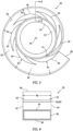
FIG. 3 is a diagrammatic representation of a present disclosure spool embodiment. -
FIGS. 4-7 are diagrammatic representations of a flow channel cross-section. -
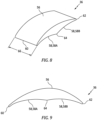
FIG. 8 is a diagrammatic isometric view of a stator vane embodiment. -
FIG. 9 is a diagrammatic isometric view of a stator vane embodiment. -
FIGS. 10A-C are diagrammatic illustrations of vane passage configurations. -
FIG. 11 is a diagrammatic illustration of a vane passage having gas flow ribs. -
FIG. 12 is a diagrammatic representation of a present disclosure spool embodiment having flow diverters. - Referring to
FIG. 1 , an example of an internal combustion engine is diagrammatically shown in the form of arotary engine 20. The present disclosure is not limited to use with rotary engines. Therotary engine 20 includes a plurality of similar axially alignedrotary units 22 driving a common eccentric shaft. Therotary engine 20 shown diagrammatically inFIG. 1 includes fourrotary units 22 but it is understood that theengine 20 could comprise any number ofrotary units 22. The present disclosure is not limited to use with any particularrotary engine 20 configuration. Each of therotary units 22 includes an exhaust port 24 for collecting combustion gases produced in the respectiverotary unit 22. Theengine 20 includes anexhaust manifold 26 configured to be paired with the exhaust ports 24. Anexhaust pipe 28 connects theexhaust manifold 26 to a scroll 30 (sometimes referred to as a "volute") that organizes the combustion gases for entry into aturbine 32. Theturbine 32 may be connected to compressor (not shown) that draws in air and provides it to therotary engine 20 for use in combustion. -
FIG. 2 illustrates an embodiment of an exhaust manifold 26 (sometimes referred to as an "exhaust header") that includes aninitial segment 26A for eachrotary unit 22 and arespective manifold pipe 26B extending from eachinitial segment 26A to acollector 26C. As can be seen inFIG. 2 , each of themanifold pipes 26B (four shown in the exemplary exhaust manifold 26) are combined into thecollector 26C. In theexhaust manifold 26 example shown inFIG. 2 , themanifold pipes 26B are combined into thecollector 26C in a stacked arrangement and thecollector 26C is oblong or oval shaped. In alternative embodiments, thecollector 26C may be circular. The present disclosure is not limited to thisparticular collector 26C configuration. Themanifold pipes 26B are typically configured (e.g., length, diameter, routing, and the like) so that the combustion gases exiting eachrotary unit 22 are subjected to a similar pressure and flow profile. In this manner, the operating parameters of eachrotary unit 22 are made as uniform as possible, thereby facilitating collective operation of therotary units 22 of therotary engine 20. Anexhaust pipe 28 extends between theexhaust manifold collector 26C and the inlet of thescroll 30. In those embodiments wherein thecollector 26C is oblong / oval shaped, theexhaust pipe 28 between thecollector 26C and the inlet of thescroll 30 may also be oblong / oval shaped. - The
scroll 30 embodiment shown inFIG. 2 may be described as a single port annular scroll; i.e., the combustion gases from theexhaust manifold 26 are directed into a single port of theannular scroll 30. Thescroll 30 is configured to organize the combustion gases to produce a flow of combustion gases exiting thescroll 30 and entering theturbine 32 at a high tangential velocity; i.e., a high exit swirl. - Each
rotary unit 22 of therotary engine 20 operates in a cyclic manner, periodically producing combustion gases. The collective flow of combustion gases from therotary engine 20, therefore, includes a periodic portion that may be referred to as "pulsation portion". The combustion gases exiting a conventional scroll (i.e., entering the turbine inlet) typically have circumferential and radial flow nonuniformities as a function of time. In other words, the aforesaid non-uniformities may be spatially disposed (e.g., circumferentially, radially) and variable as a function of time. This non-uniform gas flow entering the turbine very often decreases the turbine (isentropic) efficiency and subjects the turbine to periodic excitation forces that over time can cause structural effects; e.g., fatigue. Historically, some axial turbines have addressed this issue by adding one or more turbine initial stages (sometimes referred to as a "sacrificial stages") configured to mitigate or "settle" the gas flow non-uniformities. Disadvantages to this approach include the greater size, additional weight, and additional cost associated with sacrificial turbine stages. - Referring to
FIG. 3 , thepresent disclosure scroll 30 is configured to attenuate the pulsatile portion of the combustion gas flow and thereby increase turbine efficiency and decrease periodic excitation forces potentially detrimental to the turbine. The present disclosure scroll may be used, for example, with an axial reaction turbine, an axial impulse turbine, or the like. - The
present disclosure scroll 30 includes a generally annularly extendingflow channel 34, a plurality ofstator vanes 36, and ascroll inlet 38. The stator vanes 36 are disposed in theflow channel 34, spaced apart from one another and disposed around the circumference of thescroll 30. Thescroll 30 includes acenter axis 40. Theflow channel 34 extends from thescroll inlet 38 to aterminal end 41 disposed at avane passage 68 as will be described herein. Thescroll inlet 38 may be aligned with astator vane 36. - The
flow channel 34 may be defined by a firstaxial sidewall 42, a secondaxial sidewall 44, and an outerradial wall 46. The first and secondaxial sidewalls radial wall 46 extends between the first and secondaxial sidewalls flow channel 34.FIG. 3 diagrammatically illustrates a side view of apresent disclosure scroll 30 embodiment, shown open (e.g., an axial sidewall removed) to permit thestator vanes 36 to be seen. In the planar view ofFIG. 3 , thecenter axis 40 extends perpendicularly, into and out of the page.FIGS. 4-7 diagrammatically showscroll 30 cross-sections taken at section X-X to illustratedifferent flow channel 34 configurations. - In some embodiments, the first and second
axial sidewalls radial wall 46 may form aflow channel 34 having a rectangular-like cross-section wherein the first and secondaxial sidewalls radial wall 46 is substantially perpendicular to the first and secondaxial sidewalls FIG. 3 . In these embodiments, thewidth 48 of theflow channel 34 may be substantially constant. In some embodiments, the first and secondaxial sidewalls flow channel 34 width between the outer radial limit of the flow channel 34 (i.e., at the outer radial wall 46) and the inner radial limit of theflow channel 34; e.g., seeFIGS. 5 and 6 . In other embodiments, one or both of the first and secondaxial sidewalls axial sidewalls axial sidewalls axial sidewall axial sidewall flow channel 34 width that varies between the outer radial limit of the flow channel 34 (i.e., at the outer radial wall 46) and the inner radial limit of theflow channel 34; e.g., seeFIG. 7 . Theflow channel 34 configurations shown inFIGS. 3-7 are non-limiting examples. - The intersection between the outer
radial wall 46 and one or both the first and secondaxial sidewalls radial wall 46 may intersect directly with anaxial sidewall 42, 44 (e.g., a perpendicular intersection), or the intersection between the outerradial wall 46 and anaxial sidewall radial wall 46 and theaxial sidewall radial wall 46 andaxial sidewall - In some embodiments (e.g., see
FIG. 3 ), the outerradial wall 46 may be a planar surface. In some embodiments, the outerradial wall 46 may be arcuately shaped. The present disclosure is not limited to any particular outerradial wall 46 configuration. - The outer
radial wall 46 is disposed radially outside of thestator vanes 36 and is spaced apart from the outer radial surface of each stator vane 36 (e.g., thesuction side surface 56 of the respective stator vane 36) by a distance R; e.g., R1 for afirst stator vane 36, R2 for asecond stator vane 36, R3 for athird stator vane 36, and the like. The portion of theflow channel 34 disposed between thesuction side surface 56 of arespective stator vane 36 and the outerradial wall 46 may be referred to as the "outerflow channel portion 50". - In some embodiments (e.g., see
FIG. 3 ), the outerradial wall 46 spirals inwardly starting at thescroll inlet 38 as the outerradial wall 46 extends circumferentially around thescroll 30. In this embodiment, the outerradial wall 46 may be described as non-axisymmetric (about the center axis 40). The inward spiral of the outerradial wall 46 can be seen by the change in radial distances R between thestator vanes 36 and the outerradial wall 46 as theflow channel 34 extends circumferentially from thescroll inlet 38; e.g., R1 > R2 > R3, and so on. In these outerradial wall 46 non-axisymmetric embodiments, the cross-sectional area of the outer flow channel portion 50 (i.e., in a plane perpendicular to theflow channel 34 and to the collective circumferential direction of flow within the channel 34) decreases in the spiral direction away from thescroll inlet 38. In some embodiments, theflow channel 34 with an outerflow channel portion 50 having a cross-sectional area that decreases in a circumferential direction (as a result of the non-axisymmetric outer radial wall 46) may be described as extending from thescroll inlet 38 to theterminal end 41 where the outerflow channel portion 50 terminates at avane passage 68; e.g., seeFIG. 3 . The present disclosure flow channel is not limited to this embodiment. - In some embodiments, the outer
radial wall 46 may extend circumferentially around thescroll 30 at a constant spacing from thestator vanes 36 and the radial distances between thestator vanes 36 and the outerradial wall 46 remain constant; e.g., R1 = R2 = R3, and so on. In these outerradial wall 46 axisymmetric embodiments (symmetric about the center axis 40), the cross-sectional area of the outerflow channel portion 50 remains constant in the spiral direction away from thescroll inlet 38. - The stator vanes 36 are configured to direct air traveling circumferentially within the
flow channel 34 radially inwardly into anannular region 52 disposed radially between thestator vanes 36 and a turbine annulusouter diameter surface 54. The aforesaidannular region 52 may be referred to as an "annular collection region 52". The gas flow entering theannular collection region 52 subsequently passes axially into the turbine while maintaining its angular momentum. - Referring to
FIGS. 8 and 9 , in the embodiment shown inFIGS. 3 ,8, and 9 , eachstator vane 36 has asuction side surface 56, apressure side surface 58, a leadingedge 60, and a trailingedge 62. Thepressure side surface 58 includes a pressure side (PS)intervane passage portion 58A and a trailing edge (TE)annular passage portion 58B. The PSintervane passage portion 58A extends from the leadingedge 60 to the TE arcannular portion 58B, and the TE arcannular portion 58B extends from the trailingedge 62 to the PSintervane passage portion 58A. The PSintervane passage portion 58A and the TE arcannular portion 58B may meet at aninflection point 64. The TE arcannular portions 58B of the stator vanes define an outer radial perimeter of theannular collection region 52. Eachstator vane 36 has awidth 66 that extends between theaxial sidewalls flow channel 34. The leadingedge 60 of astator vane 36 may be arcuately configured (e.g., as a radiused surface that is parti-circular or parti-elliptical, or the like), and the trailingedge 62 of astator vane 36 may be arcuately configured (e.g., as a radiused surface that is parti-circular or parti-elliptical, or the like). The present disclosure is not limited to thestator vane 36 embodiment shown inFIGS. 3 ,8, and 9 , and the present disclosure is not limited to embodiments wherein all of thestator vanes 36 are the configured the same. - In some embodiments, the
pressure side surface 58 and thesuction side surface 56 of eachstator vane 36 extend widthwise between and intersect with the first and secondaxial sidewalls flow channel 34. The pressure side and suction side surfaces 56, 58 may intersect directly with anaxial sidewall 42, 44 (e.g., a perpendicular intersection), or the intersection may be radiused, or a fillet surface (e.g., planar or arcuate) may extend therebetween, or there may be an undercut disposed between thepressure side surface 58 and anaxial sidewall suction side surface 56 and anaxial sidewall axial sidewalls pressure side surface 58 and/or thesuction side surface 56. Some sidewall configurations of this type may be described as having a "C" like shape. The present disclosure is not limited to any particular intersection configuration between thepressure sidewall 58 and a flow channelaxial sidewall suction sidewall 56 and a flow channelaxial sidewall stator vane 36 may be configured to extend widthwise between, but not intersect with, the firstaxial sidewall 42 and/or the secondaxial sidewall 44 of theflow channel 34. In those embodiments wherein astator vane 36 extends widthwise between but does not intersect with anaxial sidewall stator vane 36 may be spaced apart from the respectiveaxial sidewall - As stated above, the
stator vanes 36 are disposed in theflow channel 34, spaced apart from one another and disposed around the circumference of thescroll 30. Thepresent disclosure scroll 30 diagrammatically shown inFIG. 3 is shown with six (6)stator vanes 36 spaced apart from one another and disposed around the circumference of thescroll 30. Embodiments of thepresent disclosure scroll 30 may have as few as two (2)stator vanes 36 and may include more than six (6) stator vanes 36. The present disclosure is not limited to any particular number ofstator vanes 36. - The circumferential spacing of the
stator vanes 36 produces avane passage 68 disposed between each pair ofadjacent stator vanes 36; e.g., avane passage 68 is formed between forward and aftadjacent stator vanes 36 within theflow channel 34. A first point in theflow channel 34 that encounters the circumferential flow in theflow channel 34 before a second point is said to be "forward" or "upstream" of the second point, or conversely the second point is said to be "aft" or "downstream" of the first point. More specifically, eachvane passage 68 between adjacent forward andaft stator vanes 36 is defined by a portion of thesuction side surface 56 of aforward stator vane 36 and the PSintervane passage portion 58A of the adjacentaft stator vane 36. Eachvane passage 68 may extend in a direction that has a radial component and a circumferential component (i.e., thevane passage 68 spirals inwardly), as shown inFIG. 3 . Eachvane passage 68 extends alength 70 between the outerflow channel portion 50 and theannular collection region 52. In some embodiments, thestator vanes 36 may be configured to define avane passage 68 having length over width ratio (which may be referred to as a length over hydraulic diameter ratio, or L/Dh) greater than one (1) to impart desirable flow directionality and tangential velocity. In eachvane passage 68, the distance between the portion of thesuction side surface 56 of theforward stator vane 36 and the PSintervane passage portion 58A of the adjacentaft stator vane 36 may be referred to as the "height" or "H" of thevane passage 68. - Referring to
FIGS. 10A-C , in some embodimentsadjacent stator vanes 36 may be configured such that thevane passage 68 therebetween has a uniform height along thevane passage length 70; seeFIG. 10A , H1 = H2. In some embodiments,adjacent stator vanes 36 may be configured such that thevane passage 68 therebetween converges along thevane passage length 70 between the outerflow channel portion 50 and theannular collection region 52; e.g., seeFIG. 10B , H1 > H2. In some embodiments,adjacent stator vanes 36 may be configured such that thevane passage 68 therebetween diverges along thevane passage length 70 between the outerflow channel portion 50 and theannular collection region 52; e.g., seeFIG. 10C , H1 < H2. - In some embodiments, like that diagrammatically shown in
FIG. 3 , thestator vanes 36 may be uniformly configured and uniformly spaced around the circumference of thespool 30, which produces uniformly configuredvane passages 68; e.g., allvane passages 68 have the same geometric configuration. In a "uniform" spool /stator vane 36 configuration like this, the gas flow will enter theannular collection region 52 at equidistant circumferential points; e.g., in a spool configuration having six (6)uniform stator vanes 36,vane passages 68 are disposed at sixty degrees (60°) angular spacings. The present disclosure is not, however, limited to this uniform configuration. For example, in some embodiments thestator vanes 36 may not be uniformly configured, but rather configured to definevane passages 68 that are not circumferentially equidistant one another; e.g., assuming six (6)stator vanes 36, allvane passages 68 may not be disposed at sixty degree (60°) angular spacings. As will be described herein, thepresent disclosure spool 30 is configured to increase the uniformity of the gas flow into the turbine. In some applications, the gas flow entering thespool 30 may be such that gas flow entering theannular collection region 52 from circumferentially equidistant positionedvane passages 68 may improve the uniformity of the gas flow into the turbine, or conversely in some applications gas flow entering thespool 30 may be such that gas flow entering theannular collection region 52 from circumferentially non-equidistant positionedvane passages 68 may improve the uniformity of the gas flow into the turbine. - In some embodiments like that shown in
FIG. 3 , thestator vane 36 features (e.g., thesuction side surface 56, thepressure side surface 58, the leadingedge 60, the trailing edge 62) may extend widthwise parallel to thecenter axis 40 of thescroll 30. In some embodiments, thestator vane 36 features (e.g., thesuction side surface 56, thepressure side surface 58, the leadingedge 60, the trailing edge 62) may have an axial twist in a widthwise direction and are not therefore parallel to thecenter axis 40 of thescroll 20. Here again, thepresent disclosure spool 30 is configured to increase the uniformity of the gas flow into the turbine. In some applications, one ormore stator vanes 36 having features with an axial twist in a widthwise direction may be included to improve the uniformity of the gas flow into the turbine. - Referring to
FIG. 11 , in some embodiments, one or more gasflow guide panels 72 may be disposed within avane passage 68 to facilitate guiding gas flow passing through avane passage 68. In some configurations, thegas flow panels 72 may be configured to provide structural stiffening of thevane passage 68. A gasflow guide panel 72 may extend widthwise a portion or all of the distance between theaxial sidewalls flow guide panel 72 may include a first portion connected to a first of theaxial sidewalls axial sidewalls flow guide panel 72 may extend a portion or all of the length of avane passage 68. - In some embodiments, the
stator vanes 36 may be mounted so as to be pivotable within theflow channel 34 and connected to an actuating device (not shown) configured to pivot thestator vanes 36; e.g., to change the angle of attack of the leadingedge 60 relative to the gas flow traveling circumferentially within theflow channel 34. - In some embodiments, one or more flow diverters 74 (sometimes referred to as "ski jumps") may be attached to an interior surface of the
flow channel 34. Aflow diverter 74 may be attached to a surface and be configured to divert flow away from the surface to which theflow diverter 74 is attached. InFIG. 12 for example, a plurality offlow diverters 74 are shown attached to the outerradial surface 46 of theflow channel 34 to divert circumferential flow within theflow channel 34 away from the outerradial wall 46 and more generally toward the radially inward stator vanes 36. - In some embodiments, the
stator vanes 36 may be hollow bodies. In those embodiments, the interior cavity of a stator vane 36 (defined at least in part by the suction side surface and the pressure side surface) may include structural elements (e.g., ribs, struts, and the like). In some embodiments, an exterior surface of astator vane 36 may include elements (e.g., ribs) that provide structural support and/or may function to guide gas flow. In some embodiments, one or more struts may extend within theflow channel 34 to support astator vane 36. - As stated above, embodiments of the present disclosure scroll are configured to increase the uniformity of gas entering the turbine, including mitigating the pulsed portion of the combustion gas flow and thereby decrease the entry of pulsed gas flow into the turbine. The scroll embodiment described above having an outer
radial wall 46 that extends non-axisymmetrically relative to thecenter axis 40 of the scroll (i.e., a radially inward spiral) and thereby creates anouter flow channel 34 cross-sectional area that decreases in the spiral direction away from the scroll inlet is understood to provide particular utility. The radially decreasingouter flow channel 34 facilitates guiding gas flow towards thestator vanes 36 andvane passages 68. It is understood that the radially decreasingouter flow channel 34 improves gas flow velocity uniformity (e.g., a nearly uniform Mach number as a function of time) circumferentially within theflow channel 34, which in turn attenuates gas flow pulsation, decreases circumferential and radial flow nonuniformity as a function of time, and maintains and/or generates high tangential gas flow velocity (i.e., high exit swirl) prior to the turbine. The decrease in pulsatile flow is also understood to provide noise reduction. - While the principles of the disclosure have been described above in connection with specific apparatuses and methods, it is to be clearly understood that this description is made only by way of example and not as limitation on the scope of the disclosure. Specific details are given in the above description to provide a thorough understanding of the embodiments. However, it is understood that the embodiments may be practiced without these specific details.
- It is noted that the embodiments may be described as a process which is depicted as a flowchart, a flow diagram, a block diagram, etc. Although any one of these structures may describe the operations as a sequential process, many of the operations can be performed in parallel or concurrently. In addition, the order of the operations may be rearranged. A process may correspond to a method, a function, a procedure, a subroutine, a subprogram, etc.
- The singular forms "a," "an," and "the" refer to one or more than one, unless the context clearly dictates otherwise. For example, the term "comprising a specimen" includes single or plural specimens and is considered equivalent to the phrase "comprising at least one specimen." The term "or" refers to a single element of stated alternative elements or a combination of two or more elements unless the context clearly indicates otherwise. As used herein, "comprises" means "includes." Thus, "comprising A or B," means "including A or B, or A and B," without excluding additional elements.
- It is noted that various connections are set forth between elements in the present description and drawings (the contents of which are included in this disclosure by way of reference). It is noted that these connections are general and, unless specified otherwise, may be direct or indirect and that this specification is not intended to be limiting in this respect. Any reference to attached, fixed, connected or the like may include permanent, removable, temporary, partial, full and/or any other possible attachment option.
- No element, component, or method step in the present disclosure is intended to be dedicated to the public regardless of whether the element, component, or method step is explicitly recited in the claims. No claim element herein is to be construed under the provisions of 35 U.S.C. 112(f) unless the element is expressly recited using the phrase "means for." As used herein, the terms "comprise", "comprising", or any other variation thereof, are intended to cover a non-exclusive inclusion, such that a process, method, article, or apparatus that comprises a list of elements does not include only those elements but may include other elements not expressly listed or inherent to such process, method, article, or apparatus.
- While various inventive aspects, concepts and features of the disclosures may be described and illustrated herein as embodied in combination in the exemplary embodiments, these various aspects, concepts, and features may be used in many alternative embodiments, either individually or in various combinations and sub-combinations thereof. Unless expressly excluded herein all such combinations and sub-combinations are intended to be within the scope of the present application. Still further, while various alternative embodiments as to the various aspects, concepts, and features of the disclosures--such as alternative materials, structures, configurations, methods, devices, and components, and so on--may be described herein, such descriptions are not intended to be a complete or exhaustive list of available alternative embodiments, whether presently known or later developed. For example,
present disclosure rotors 32 are described herein as having axial end surfaces andperipheral surfaces 42. The term "surface" as used may include a single surface or may include a plurality of surface sections that collectively form a surface. Hence, the term "surface" is not intended to be limited to a single planar surface. Those skilled in the art may readily adopt one or more of the inventive aspects, concepts, or features into additional embodiments and uses within the scope of the present application even if such embodiments are not expressly disclosed herein. For example, in the exemplary embodiments described above within the Detailed Description portion of the present specification, elements may be described as individual units and shown as independent of one another to facilitate the description. In alternative embodiments, such elements may be configured as combined elements. It is further noted that various method or process steps for embodiments of the present disclosure are described herein. The description may present method and/or process steps as a particular sequence. However, to the extent that the method or process does not rely on the particular order of steps set forth herein, the method or process should not be limited to the particular sequence of steps described. As one of ordinary skill in the art would appreciate, other sequences of steps may be possible. Therefore, the particular order of the steps set forth in the description should not be construed as a limitation.
Claims (15)
- A turbine scroll (30) for use with an axial turbine (32), comprising:a flow channel (34) defined by an outer radial wall (46) extending between a first axial sidewall (42) and a second axial sidewall (44), the first axial sidewall (42) and second axial sidewall (44) spaced widthwise apart from one another, the flow channel (34) extending circumferentially around a center axis (40);a scroll inlet (38) configured to permit gas flow into the flow channel (34);a plurality of stator vanes (36) disposed within the flow channel (34), spaced apart from one another and disposed around a circumference of the scroll (30); anda plurality of vane passages (68), each vane passage (68) defined between adjacent said stator vanes (36) of the plurality of stator vanes (36), each vane passage (68) is open to an outer flow channel portion (50) of the flow channel (34) disposed radially between the stator vanes (36) and the outer radial wall (46) and is open to an annular region (52) disposed radially inside of the plurality of stator vanes (36), the vane passages (68) configured to direct gas flow in an inwardly spiraling direction having a radially inward component and a circumferential component.
- The turbine scroll (30) of claim 1, wherein the plurality of stator vanes (36) are uniformly configured.
- The turbine scroll (30) of claim 1 or 2, wherein the plurality of stator vanes (36) are uniformly spaced around the circumference of the scroll (30).
- The turbine scroll (30) of any preceding claim, wherein the outer radial wall (46) of the of the flow passage is non-axisymmetric about the center axis (40).
- The turbine scroll (30) of any preceding claim, wherein the outer radial wall (46) spirals radially inwardly around the circumference of the scroll (30), and the outer flow channel portion (50) has a cross-sectional area that decreases circumferentially.
- The turbine scroll (30) of any preceding claim, wherein each vane passage (68) of the plurality of vane passages (68) has a height (H1, H2) and an arcuately extending length (70), and the height (HI, H2) is uniform along the arcuately extending length (70).
- The turbine scroll (30) of any preceding claim, wherein the plurality of vane passages (68) includes a first vane passage (68) having a first geometric configuration, and a second vane passage (68) having a second geometric configuration, and the first geometric configuration is different from the second geometric configuration.
- The turbine scroll (30) of any preceding claim, wherein each stator vane (36) of the plurality of stator vanes (36) extends widthwise between the first axial sidewall (42) and the second axial sidewall (44), optionally wherein each stator vane (36) of the plurality of stator vanes (36) is connected to the first axial sidewall (42) and the second axial sidewall (44).
- The turbine scroll (30) of claim 8, wherein each stator vane (36) of the plurality of stator vanes (36) extends widthwise parallel to the center axis (40).
- The turbine scroll (30) of claim 8, wherein at least one of the plurality of stator vanes (36) extends widthwise non-parallel to the center axis (40).
- The turbine scroll (30) of any preceding claim, wherein the plurality of stator vanes (36) includes a first stator vane (36) having a first geometric configuration, and a second stator vane (36) having a second geometric configuration, and the first geometric configuration is different from the second geometric configuration.
- The turbine scroll (30) of any preceding claim, wherein each stator vane (36) has a suction side surface (56) extending between a leading edge (60) and a trailing edge (62), and a pressure side surface (58) having a pressure side intervane passage portion (58A) and a trailing edge (62) arc annular portion (58B), wherein the pressure side intervane passage portion (58A) extends between the leading edge (60) and the trailing edge arc annular portion (58B), and the trailing edge arc annular portion (58B) extends between the trailing edge (62) and the pressure side intervane passage portion (58A).
- The turbine scroll (30) of claim 12, wherein the trailing edge arc annular portions (58B) of the plurality of stator vanes (36) define an outer radial perimeter of the annular region (52) disposed radially inside of the plurality of stator vanes (36).
- The turbine scroll (30) of claim 12 or 13, wherein each pair of adjacent said stator vanes (36) includes a forward stator vane and an aft stator vane, and each said vane passage (68) is defined by a portion of the suction side surface (56) of the forward stator vane and the pressure side intervane passage portion (58A) of the pressure side surface (58) of the aft stator vane (36).
- A rotary engine (20), comprising:a plurality of rotary units (22) in communication with one another, each rotary unit (22) having an exhaust port (24);an exhaust manifold (26) connected to the exhaust port (24) of each rotary unit (22), the exhaust manifold (26) configured to periodically receive combustion gases from each exhaust port (24) during operation of the engine (20);the turbine scroll (30) of any preceding claim, the turbine scroll (30) in fluid communication with the exhaust manifold (26) and configured to receive the periodic flow of combustion gases,wherein the turbine scroll (30) is configured to attenuate the periodic flow of combustion gases.
Applications Claiming Priority (1)
| Application Number | Priority Date | Filing Date | Title |
|---|---|---|---|
| US18/129,616 US12442310B2 (en) | 2023-03-31 | 2023-03-31 | Turbine engine scroll for use with an internal combustion engine |
Publications (1)
| Publication Number | Publication Date |
|---|---|
| EP4438859A1 true EP4438859A1 (en) | 2024-10-02 |
Family
ID=90571831
Family Applications (1)
| Application Number | Title | Priority Date | Filing Date |
|---|---|---|---|
| EP24167614.7A Pending EP4438859A1 (en) | 2023-03-31 | 2024-03-28 | Turbine engine scroll for use with an internal combustion engine |
Country Status (3)
| Country | Link |
|---|---|
| US (1) | US12442310B2 (en) |
| EP (1) | EP4438859A1 (en) |
| CA (1) | CA3233603A1 (en) |
Cited By (1)
| Publication number | Priority date | Publication date | Assignee | Title |
|---|---|---|---|---|
| EP4741634A1 (en) * | 2024-11-08 | 2026-05-13 | Pratt & Whitney Canada Corp. | Aircraft propulsion system with turbocompressor unit |
Citations (5)
| Publication number | Priority date | Publication date | Assignee | Title |
|---|---|---|---|---|
| JPS55167502U (en) * | 1979-05-21 | 1980-12-02 | ||
| US20140234094A1 (en) * | 2011-11-03 | 2014-08-21 | Duerr Cyplan Ltd. | Turbomachines having guide ducts |
| US20150300243A1 (en) * | 2012-12-05 | 2015-10-22 | Mack Trucks, Inc. | Method for adjusting exhaust gas temperature and turbine with bypass arrangement |
| DE102015223257A1 (en) * | 2015-11-25 | 2017-06-01 | Volkswagen Aktiengesellschaft | Exhaust gas turbine, exhaust gas turbocharger, internal combustion engine and motor vehicle |
| US20200291800A1 (en) * | 2019-03-12 | 2020-09-17 | Garrett Transportation I Inc. | Turbocharger with twin-scroll turbine housing and twin vaned nozzle ring for directing exhaust gases from each scroll onto turbine wheel in interleaved fashion |
Family Cites Families (15)
| Publication number | Priority date | Publication date | Assignee | Title |
|---|---|---|---|---|
| US6302647B1 (en) | 2000-05-10 | 2001-10-16 | General Motors Corporation | Turbine inlet scroll |
| US6834501B1 (en) | 2003-07-11 | 2004-12-28 | Honeywell International, Inc. | Turbocharger compressor with non-axisymmetric deswirl vanes |
| US7931437B1 (en) | 2007-09-21 | 2011-04-26 | Florida Turbine Technologies, Inc. | Turbine case with inlet and outlet volutes |
| US8113770B2 (en) * | 2009-02-03 | 2012-02-14 | Honeywell International Inc. | Turbine assembly for an exhaust gas-driven turbocharger having a variable nozzle |
| JP5769407B2 (en) | 2010-02-01 | 2015-08-26 | 三菱重工業株式会社 | Sheet metal turbine housing |
| US8573929B2 (en) * | 2010-04-30 | 2013-11-05 | Honeywell International Inc. | Turbocharger with turbine nozzle vanes and an annular rotary bypass valve |
| DE102012202907B4 (en) * | 2012-02-27 | 2018-09-20 | Continental Automotive Gmbh | Exhaust gas turbocharger with relatively rotatable Leitgitterringen |
| DE112014004823T5 (en) | 2013-11-25 | 2016-07-21 | Borgwarner Inc. | Asymmetrical double-flow spiral |
| US20150159660A1 (en) * | 2013-12-06 | 2015-06-11 | Honeywell International Inc. | Axial turbine with radial vnt vanes |
| US9494189B2 (en) * | 2014-04-04 | 2016-11-15 | GM Global Technology Operations LLC | Turbocharger bearing housing oil groove |
| GB2544809B (en) | 2015-11-30 | 2019-10-02 | Perkins Engines Co Ltd | Internal combustion with asymmetric twin scroll turbine and increased efficiency |
| CN107725195A (en) | 2017-11-23 | 2018-02-23 | 上海泛智能源装备有限公司 | A kind of air inlet volute and gas turbine |
| US11248488B2 (en) * | 2019-03-12 | 2022-02-15 | Garrett Transportation I Inc. | Method for making a twin-vaned nozzle ring assembly for a turbocharger with twin-scroll turbine housing for directing exhaust gases from each scroll onto turbine wheel in interleaved fashion |
| WO2021140569A1 (en) * | 2020-01-07 | 2021-07-15 | 三菱重工エンジン&ターボチャージャ株式会社 | Turbine and turbocharger |
| GB202019182D0 (en) | 2020-12-04 | 2021-01-20 | Cummins Ltd | Compressor |
-
2023
- 2023-03-31 US US18/129,616 patent/US12442310B2/en active Active
-
2024
- 2024-03-27 CA CA3233603A patent/CA3233603A1/en active Pending
- 2024-03-28 EP EP24167614.7A patent/EP4438859A1/en active Pending
Patent Citations (5)
| Publication number | Priority date | Publication date | Assignee | Title |
|---|---|---|---|---|
| JPS55167502U (en) * | 1979-05-21 | 1980-12-02 | ||
| US20140234094A1 (en) * | 2011-11-03 | 2014-08-21 | Duerr Cyplan Ltd. | Turbomachines having guide ducts |
| US20150300243A1 (en) * | 2012-12-05 | 2015-10-22 | Mack Trucks, Inc. | Method for adjusting exhaust gas temperature and turbine with bypass arrangement |
| DE102015223257A1 (en) * | 2015-11-25 | 2017-06-01 | Volkswagen Aktiengesellschaft | Exhaust gas turbine, exhaust gas turbocharger, internal combustion engine and motor vehicle |
| US20200291800A1 (en) * | 2019-03-12 | 2020-09-17 | Garrett Transportation I Inc. | Turbocharger with twin-scroll turbine housing and twin vaned nozzle ring for directing exhaust gases from each scroll onto turbine wheel in interleaved fashion |
Cited By (1)
| Publication number | Priority date | Publication date | Assignee | Title |
|---|---|---|---|---|
| EP4741634A1 (en) * | 2024-11-08 | 2026-05-13 | Pratt & Whitney Canada Corp. | Aircraft propulsion system with turbocompressor unit |
Also Published As
| Publication number | Publication date |
|---|---|
| CA3233603A1 (en) | 2025-10-30 |
| US12442310B2 (en) | 2025-10-14 |
| US20240328323A1 (en) | 2024-10-03 |
Similar Documents
| Publication | Publication Date | Title |
|---|---|---|
| EP1507977B1 (en) | Discrete passage diffuser | |
| EP2778431B1 (en) | Centrifugal compressors and methods of designing diffuser vanes for the same | |
| CN100443735C (en) | A guide vane assembly for a gas turbine engine | |
| US9004850B2 (en) | Twisted variable inlet guide vane | |
| US5203674A (en) | Compact diffuser, particularly suitable for high-power gas turbines | |
| EP3708779B1 (en) | Turbocharger with twin-scroll turbine housing and twin vaned nozzle ring for directing exhaust gases from each scroll onto turbine wheel in interleaved fashion | |
| RU2354852C2 (en) | Gas turbine compressor device and compressor housing element | |
| US20160115971A1 (en) | Diffuser pipe with splitter vane | |
| EP3741960A1 (en) | Method for making a twin-vaned nozzle ring assembly for a turbocharger | |
| US12442310B2 (en) | Turbine engine scroll for use with an internal combustion engine | |
| EP3722616A1 (en) | Deswirler assembly for a centrifugal compressor | |
| US11286951B2 (en) | Diffuser pipe with exit scallops | |
| US11435079B2 (en) | Diffuser pipe with axially-directed exit | |
| EP3832144A1 (en) | Diffuser pipe with radially-outward exit | |
| CN107849969A (en) | Pulse separation axial flow turbo-machine level with radial-axial inlet guide vane | |
| EP2899369B1 (en) | Multistage axial flow compressor | |
| JP7179841B2 (en) | Diffuser device for exhaust gas turbine | |
| GB2131100A (en) | Diffuser | |
| US20260015944A1 (en) | Turbine engine scroll for use with an internal combustion engine | |
| CN106988797B (en) | System for integrated section of turbine | |
| JP7541580B2 (en) | Return channel having non-constant return channel vane pitch and centrifugal turbomachine including same - Patents.com | |
| CN115698514B (en) | Compressor stabilizer channel | |
| EP3567224B1 (en) | Turbocharger having a meridionally divided turbine housing | |
| JP2022531884A (en) | Static blade for centrifugal compressor | |
| RU2772097C2 (en) | Diffuser device of turbine operating on exhaust gases |
Legal Events
| Date | Code | Title | Description |
|---|---|---|---|
| PUAI | Public reference made under article 153(3) epc to a published international application that has entered the european phase |
Free format text: ORIGINAL CODE: 0009012 |
|
| STAA | Information on the status of an ep patent application or granted ep patent |
Free format text: STATUS: THE APPLICATION HAS BEEN PUBLISHED |
|
| AK | Designated contracting states |
Kind code of ref document: A1 Designated state(s): AL AT BE BG CH CY CZ DE DK EE ES FI FR GB GR HR HU IE IS IT LI LT LU LV MC ME MK MT NL NO PL PT RO RS SE SI SK SM TR |
|
| STAA | Information on the status of an ep patent application or granted ep patent |
Free format text: STATUS: REQUEST FOR EXAMINATION WAS MADE |
|
| 17P | Request for examination filed |
Effective date: 20250402 |