EP4438851A2 - Rfid actuated release of mill from whipstock - Google Patents
Rfid actuated release of mill from whipstock Download PDFInfo
- Publication number
- EP4438851A2 EP4438851A2 EP24195069.0A EP24195069A EP4438851A2 EP 4438851 A2 EP4438851 A2 EP 4438851A2 EP 24195069 A EP24195069 A EP 24195069A EP 4438851 A2 EP4438851 A2 EP 4438851A2
- Authority
- EP
- European Patent Office
- Prior art keywords
- whipstock
- mill
- radio frequency
- bottom hole
- hole assembly
- Prior art date
- Legal status (The legal status is an assumption and is not a legal conclusion. Google has not performed a legal analysis and makes no representation as to the accuracy of the status listed.)
- Granted
Links
Images





Classifications
-
- E—FIXED CONSTRUCTIONS
- E21—EARTH OR ROCK DRILLING; MINING
- E21B—EARTH OR ROCK DRILLING; OBTAINING OIL, GAS, WATER, SOLUBLE OR MELTABLE MATERIALS OR A SLURRY OF MINERALS FROM WELLS
- E21B7/00—Special methods or apparatus for drilling
- E21B7/04—Directional drilling
- E21B7/06—Deflecting the direction of boreholes
- E21B7/061—Deflecting the direction of boreholes the tool shaft advancing relative to a guide, e.g. a curved tube or a whipstock
-
- E—FIXED CONSTRUCTIONS
- E21—EARTH OR ROCK DRILLING; MINING
- E21B—EARTH OR ROCK DRILLING; OBTAINING OIL, GAS, WATER, SOLUBLE OR MELTABLE MATERIALS OR A SLURRY OF MINERALS FROM WELLS
- E21B23/00—Apparatus for displacing, setting, locking, releasing or removing tools, packers or the like in boreholes or wells
- E21B23/02—Apparatus for displacing, setting, locking, releasing or removing tools, packers or the like in boreholes or wells for locking the tools or the like in landing nipples or in recesses between adjacent sections of tubing
-
- E—FIXED CONSTRUCTIONS
- E21—EARTH OR ROCK DRILLING; MINING
- E21B—EARTH OR ROCK DRILLING; OBTAINING OIL, GAS, WATER, SOLUBLE OR MELTABLE MATERIALS OR A SLURRY OF MINERALS FROM WELLS
- E21B47/00—Survey of boreholes or wells
- E21B47/12—Means for transmitting measuring-signals or control signals from the well to the surface, or from the surface to the well, e.g. for logging while drilling
- E21B47/13—Means for transmitting measuring-signals or control signals from the well to the surface, or from the surface to the well, e.g. for logging while drilling by electromagnetic energy, e.g. radio frequency
-
- E—FIXED CONSTRUCTIONS
- E21—EARTH OR ROCK DRILLING; MINING
- E21B—EARTH OR ROCK DRILLING; OBTAINING OIL, GAS, WATER, SOLUBLE OR MELTABLE MATERIALS OR A SLURRY OF MINERALS FROM WELLS
- E21B47/00—Survey of boreholes or wells
- E21B47/12—Means for transmitting measuring-signals or control signals from the well to the surface, or from the surface to the well, e.g. for logging while drilling
- E21B47/138—Devices entrained in the flow of well-bore fluid for transmitting data, control or actuation signals
-
- E—FIXED CONSTRUCTIONS
- E21—EARTH OR ROCK DRILLING; MINING
- E21B—EARTH OR ROCK DRILLING; OBTAINING OIL, GAS, WATER, SOLUBLE OR MELTABLE MATERIALS OR A SLURRY OF MINERALS FROM WELLS
- E21B47/00—Survey of boreholes or wells
- E21B47/26—Storing data down-hole, e.g. in a memory or on a record carrier
Definitions
- This disclosure relates generally to equipment utilized and operations performed in conjunction with a subterranean well and, in an example described below, more particularly provides for RFID actuated release of a mill from a whipstock.
- a whipstock is sometimes used in well drilling operations to form a lateral or branch wellbore from a main or parent wellbore. If the main or parent wellbore is lined with casing, a window may be formed through the casing by use of the whipstock with a mill specifically designed for this purpose.
- the whipstock is releasably attached to the mill during conveyance of this equipment into the well.
- an anchor is set and the mill is released from the whipstock.
- a shearable bolt is typically used to releasably secure the whipstock to the mill.
- the bolt may be inadvertently or prematurely sheared, for example, if an obstruction is encountered during the conveyance of the equipment into the well, substantial changes in wellbore direction are encountered, etc.
- FIG. 1 Representatively illustrated in FIG. 1 is a system 10 and associated method which can embody principles of this disclosure.
- system 10 and method are merely one example of an application of the principles of this disclosure in practice, and a wide variety of other examples are possible. Therefore, the scope of this disclosure is not limited at all to the details of the system 10 and method described herein and/or depicted in the drawings.
- a bottom hole assembly 12 is being conveyed into a wellbore 14 that is lined with casing 16 and cement 18. It is desired, in this example, to drill another wellbore (such as, a branch or lateral wellbore) intersecting the wellbore 14.
- another wellbore such as, a branch or lateral wellbore
- the bottom hole assembly 12 includes an anchor 20, a whipstock 22 and a mill 24. Additional or different components (such as, a casing annular section locator, an orienting device, etc.) may be used in other examples. The scope of this disclosure is not limited to the use of any particular components or combination of components in a bottom hole assembly.
- the anchor 20 is used to secure the whipstock 22 at a desired position in the wellbore 14 for forming an exit window through the casing 16.
- the anchor 20 may be set in the wellbore 14 using a variety of different techniques, such as, by applying hydraulic pressure to a setting mechanism of the anchor, by mechanical manipulation of the anchor (for example, raising, rotating, lowering, etc.), or by inflating an elastomeric element of the anchor.
- the anchor 20 may include slips for gripping an inner surface of the casing 16, or keys that engage one or more corresponding profiles formed in the casing.
- the anchor 20 could be a packer, or an anchoring device without an annular seal element for sealing against the casing 16.
- the scope of this disclosure is not limited to use of any particular type of anchor in a bottom hole assembly, or to any particular technique for securing the anchor in a wellbore.
- the whipstock 22 is used to laterally deflect the mill 24.
- the whipstock 22 includes an inclined surface 26 formed thereon.
- the inclined surface 26 will deflect the mill laterally, thereby causing the mill to cut an opening or window through the casing 16.
- the mill 24 is of the type known to those skilled in the art as a lead or pilot mill specially configured to initiate the cutting of the window through the casing 16.
- a drill string 52 connected above the mill 24 can include other types of mills and other cutting devices, such as, watermelon mills, finishing mills, etc. The scope of this disclosure is not limited to use of any particular type or combination of mills or other cutting devices in a drill string.
- the mill 24 in this example is also specially configured for releasable attachment to the whipstock 22, as described more fully below. It is desirable for the anchor 20, the whipstock 22 and the mill 24 to be conveyed into the wellbore 14 in a single trip into the well, for convenience, efficiency and reduced expense. Thus, after the whipstock 22 has been appropriately positioned in the wellbore 14 and the anchor 20 has been set, the mill 24 is released from the whipstock and is displaced downhole while rotating, in order to begin cutting through the casing 16.
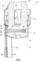
- FIG. 2 a more detailed cross-sectional view of an example of the releasable attachment between the mill 24 and the whipstock 22 is representatively illustrated.
- a collar or annular section 28 near an upper end 30 of the whipstock 22 encircles the mill 24 and is releasably secured to an outer diameter 32 of the mill positioned longitudinally between cutting structures 34, 36 on the mill.
- a retractable pin 38 is laterally slidingly received in the mill 24.
- the pin 38 is biased rightward (as viewed in FIG. 2 ) by a spring 40 or another biasing device.
- the pin 38 has a grooved head 42 that is received in an opening 44 formed through the annular section 28 of the whipstock 22.
- a latch member 46 of a hydraulic release mechanism 48 initially retains the head 42 in the opening 44, thereby preventing the pin 38 from fully retracting into the mill 24.
- the latch member 46 is configured to engage the grooved head 42 and thereby prevent retraction of the pin 38 when the latch member is in an upper position as depicted in FIG. 2 .
- Suitable hydraulic release mechanisms are described in US patent no. 10704328 and US publication no. 2020/0190908 , the entire disclosures of which are incorporated herein by this reference in their entireties for all purposes.
- a hydraulic release mechanism described in the US patent no. 10704328 and US publication no. 2020/0190908 is actuated by flowing fluid 56 through an internal flow passage 50 extending through the drill string 52. When a flow rate of the fluid 56 is increased to a predetermined level, hydraulic pressure is applied to one or more pistons of the hydraulic release mechanism 48, thereby causing the latch member 46 to be displaced downward and out of engagement with the head 42.
- FIGS. 1 & 2 system 10 hydraulic is not applied to the pistons of the hydraulic release mechanism 48 in response to a predetermined flow rate of the fluid 56 being achieved. Instead, increased pressure is applied to the pistons of the hydraulic release mechanism 48 in response to a radio frequency identification (RFID) tag 58 being displaced with the fluid 56 through (or at least into) the bottom hole assembly 12.
- RFID tag 58 may be displaced through the flow passage 50, and then through the mill 24 and into the wellbore 14.
- FIG. 3 a side view of the mill 24 and the whipstock 22 is representatively illustrated.
- the hydraulic release mechanism 48 has been actuated in response to the RFID tag 58 being displaced with the fluid 56 through the flow passage 50.
- Pistons 54 of the hydraulic release mechanism 48 have displaced downward due to increased hydraulic pressure applied to the pistons.
- the pistons 54 are connected to the latch member 46 via a rod, cable or other linkage 56.
- the latch member 46 is displaced downward out of engagement with the head 42 of the pin 38 in response to the increased hydraulic pressure applied to the pistons 54 of the hydraulic release mechanism 48.
- a recessed area 60 in a lower portion of the whipstock 22 is representatively illustrated.
- an RFID controller 62 and a valve 64 are positioned in the recessed area 60.
- An actuator 66 for the valve 64 is electrically connected to the RFID controller 62.
- Tubing 68 extends longitudinally through the recessed area 60.
- the tubing 68 provides fluid communication between the flow passage 50 (see FIG. 2 ) and the anchor 20.
- the flow of the fluid 56 through a restriction in the flow passage 50 causes an increase in pressure in the flow passage, and this increased pressure is communicated via the tubing 68 to the anchor 20, in order to set the anchor.
- the RFID tag 58 is released into the drill string 52 with the flow of the fluid 56.
- the RFID tag 58 is conveyed into and through the bottom hole assembly 12 with the fluid 56 flow.
- An antenna connected to the RFID controller 62 receives a predetermined radio frequency signal from the RFID tag 58.
- the controller 62 causes the actuator 66 to operate the valve 64, which is initially closed.
- the valve 64 is opened, fluid pressure in the tubing 68 is communicated via a flow path 70 to the pistons 54 of the release mechanism 48, thereby allowing the pin 38 to retract as described above and releasing the mill 24 from the whipstock 22.
- the release mechanism 48 may not operate hydraulically.
- the release mechanism 48 could operate electrically.
- the RFID controller 62 could be connected to an electrical solenoid that displaces the latch member 46 in response to the RFID tag 58 being displaced into the bottom hole assembly 12.
- the scope of this disclosure is not limited to hydraulic actuation of the release mechanism 48, or to any other specific details of the bottom hole assembly 12 as described herein or depicted in the drawings.
- FIG. 5 another view of the releasable attachment between the whipstock 22 and the mill 24 is representatively illustrated. In this view, one manner in which an antenna 72 may be incorporated into the whipstock 22 is depicted.
- the antenna 72 is positioned in the annular section 28 at the upper end 30 of the whipstock 22. In this position, the antenna 72 is capable of interrogating and receiving the radio frequency signal from the RFID tag 58 as it is displaced with the fluid 56 through the mill 24.
- the antenna 72 is electrically connected to the RFID controller 62.
- the antenna 72 enables the RFID controller 62 to detect when the RFID tag 58 has been displaced into (and through in this example) the bottom hole assembly 12.
- the controller causes the valve 64 to be actuated as described above, thereby releasing the mill 24 from the whipstock 22.
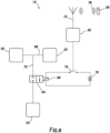
- FIG. 6 a schematic of an example of the RFID actuated system 10 is representatively illustrated.
- the manner in which the controller 62 can control operation of the valve 64 can be seen.
- the actuator 66 comprises an electrical solenoid connected between a switch 74 and a battery 76. Operation of the switch 74 is controlled by the RFID controller 62.
- the switch 74 and the battery 76 may be positioned in the whipstock 22 (for example, in the recessed area 60, see FIG. 4 ) or in another component of the system 10. In some examples, at least the switch 74 may be an integral component of the RFID controller 62.
- the scope of this disclosure is not limited to any particular elements, combination of elements or arrangement of elements as depicted in FIG. 6 or described herein.
- the antenna 72 receives the predetermined radio frequency signal 78 from the RFID tag 58.
- the controller 62 closes the switch 74. Electrical power is thereby applied from the battery 76 to the actuator 66.
- valve 64 When the actuator 66 is supplied with the electrical power from the battery 76, the valve 64 is operated to its open configuration, thereby opening the flow path 70. Increased hydraulic pressure (due to the flow of the fluid 56) is then communicated from the flow passage 50 to the pistons 54 of the release mechanism 48 via the tubing 68 and the flow path 70.
- FIG. 7 another example of the system 10 is representatively illustrated.
- the controller 62, valve 64, actuator 66, switch 74 and battery 76 are not contained in the whipstock 22. Instead, these elements and others are incorporated into an RFID sub 80 that is connected in the drill string 52 above the mill 24.
- FIG. 7 system 10 operates in a manner fundamentally similar to that described above for the FIGS. 1-6 example. Fluid pressure in the flow passage 50 due to flow of the fluid 56 is used to set the anchor 20 (see FIG. 1 ) and then, when it is desired to release the mill 24 from the whipstock 22, an RFID tag 58 is deployed into the flow passage. However, in the FIG. 7 example, the mill 24 is released in response to the RFID tag 58 being displaced into the RFID sub 80.
- FIGS. 8A & B an example of the RFID sub 80 is representatively illustrated in respective extended and retracted configurations. Note that, in the FIG. 8A extended configuration, a tubular mandrel 82 extends outwardly from an outer housing 84 of the RFID sub 80. In the FIG. 8B retracted configuration, the mandrel 82 is displaced upward into the outer housing 84.
- the actuator 66 displaces the mandrel 82 between its extended and retracted positions in response to predetermined radio frequency signals received by the antenna 72 from RFID tags 58 displaced through the flow passage 50.
- the actuator 66 may only displace the mandrel 82 from the extended to the retracted position in response to an RFID tag 58 being displaced into the flow passage 50 in the RFID sub 80.
- the mandrel 82 may also be displaced from the retracted position to the extended position in response to another RFID tag 58 being displaced into the flow passage 50 in the RFID sub 80.
- the RFID sub 80 is initially in the extended configuration and is deployed into the well with the remainder of the bottom hole assembly 12.
- the anchor 20 is set by flowing the fluid 56 through the flow passage 50 at or above a predetermined flow rate to thereby cause an increase in fluid pressure in the flow passage. This increased fluid pressure is communicated to the anchor 20 via the tubing 68 as described above.
- an RFID tag 58 is released into the drill string 52, and the RFID tag is displaced with the fluid 56 flow into the flow passage 50.
- the predetermined radio frequency signal 78 transmitted by the RFID tag 58 is received by the antenna 72 and, in response, the controller 62 operates the actuator 66.
- the mandrel 82 is displaced from the FIG. 8A extended position to the FIG. 8B retracted position by the actuator 66.
- FIG. 9 a cross-sectional view of an example of the mill 24 and the upper end 30 of the whipstock 22 is representatively illustrated. In this view, a manner in which the displacement of the mandrel 82 may be used to release the mill 24 from the whipstock 22 can be seen.
- a sleeve 86 is sealingly and reciprocally received in a bore 88 formed in the mill 24.
- the sleeve 86 may be formed on a lower end of the mandrel 82 (see FIGS. 8A & B ), or the sleeve may be a separate component connected to the lower end of the mandrel.
- a flow restriction or nozzle 90 is positioned in a lower end of the sleeve 86 in order to produce an increased fluid pressure in the flow passage 50 due to the flow of the fluid 56.
- the increased fluid pressure is communicated to the tubing 68 via openings 92 formed through a wall of the sleeve 86.
- the tubing 68 communicates the fluid pressure in the flow passage 50 to the anchor 20.
- a similar nozzle 90 may be used in the FIGS. 1-5 example to increase fluid pressure in the flow passage 50 caused by the flow of the fluid 56.
- the fluid pressure in the flow passage 50 is isolated from the flow paths 68, 70 by the valve 64.
- the valve 64 comprises an upper section of the sleeve 86 on which seals 94 are carried. In the position of the sleeve 86 shown in FIG. 9 , the seals 94 straddle openings 96, 97 formed through a wall of the mill 24.
- the position of the sleeve 86 depicted in FIG. 9 corresponds to the extended position of the mandrel 82 depicted in FIG. 8A .
- the sleeve 86 is also displaced upward, thereby placing the flow path 68 in communication with the flow passage 50 and communicating the fluid pressure in the flow passage to the anchor 20 to set the anchor.
- the anchor 20 can be set in response to an RFID tag 58 being displaced into the RFID sub 80, and then the mill 24 can be released from the whipstock 22 in response to another RFID tag 58 being displaced into the RFID sub 80.
- the predetermined radio frequency signal 78 transmitted by the RFID tag 58 is received by the antenna 72, and in response the controller 62 causes the actuator 66 to displace the mandrel 82 upward.
- This upward displacement of the mandrel 82 and the sleeve 86 formed thereon or connected thereto opens the valve 64, thereby applying increased fluid pressure first to the anchor 20 and then to the pistons 54 of the release mechanism 48 and releasing the mill 24 from the whipstock 22.
- the first RFID tag 58 used to cause setting of the anchor 20 may transmit the same radio frequency signal 78 as the second RFID tag used to cause release of the mill 24 from the whipstock 22.
- the first and second RFID tags 58 may transmit different radio frequency signals 78.
- the "set" RFID tag 58 (used to set the anchor 20) transmits a "set” radio frequency signal 78
- the subsequent "release” RFID tag 58 (used to release the mill 24 from the whipstock 22) transmits a "release" radio frequency signal 78
- the set and release radio frequency signals may be the same or different.
- the mill 24 can be released from the whipstock 22 by deploying an RFID tag 58 into a flow passage 50 in conjunction with flow of a fluid 56 through the flow passage.
- a bottom hole assembly 12 for use in a subterranean well can comprise a whipstock 22, a mill 24 releasably secured to the whipstock 22, an antenna 72 and a release mechanism 48.
- the release mechanism 48 is configured to release the mill 24 from the whipstock 22 in response to a predetermined release radio frequency signal 78 received by the antenna 72.
- the antenna 72 may be incorporated into the whipstock 22.
- the antenna 72 may be disposed in an annular section 28 of the whipstock 22 which encircles a portion of the mill 24.
- the bottom hole assembly 12 may include a valve 64 and a controller 62.
- the controller 62 may operate the valve 64 in response to the predetermined release radio frequency signal 78 received by the antenna 72.
- the valve 64 may selectively open a flow path 70 between a piston 54 of the release mechanism 48 and a flow passage 50 in the mill 24.
- the whipstock 22 may include an opening 44, a retractable pin 38 may extend from the mill 24 into the opening 44, and the mill 24 may be releasable from the whipstock 22 in response to retraction of the pin 38 from the opening 44.
- the antenna 72 may be configured to receive the predetermined release radio frequency signal 78 in response to displacement of a release radio frequency identification tag 58 into the bottom hole assembly 12.
- the bottom hole assembly 12 may include an anchor 20.
- the anchor 20 may be set in response to a predetermined set radio frequency signal 78 received by the antenna 72.
- a method for use with a subterranean well can include positioning a bottom hole assembly 12 in the well, the bottom hole assembly 12 including a mill 24 and a whipstock 22 releasably secured to the mill 24, and then releasing the mill 24 from the whipstock 22 by displacing a release radio frequency identification tag 58 into the bottom hole assembly 12.
- the displacing step may include displacing the release radio frequency identification tag 58 through the mill 24.
- the displacing step may include displacing the release radio frequency identification tag 58 through an annular section 28 of the whipstock 22.
- the annular section 28 may encircle a portion of the mill 24.
- the displacing step may include displacing the release radio frequency identification tag 58 through a sub 80, with the mill 24 being connected between the sub 80 and the whipstock 22.
- the releasing step may include an actuator 66 of the sub 80 actuating a valve 64 in the mill 24, thereby opening the valve 64 and permitting fluid communication between a flow passage 50 in the mill 24 and a flow path 70 to a piston 54 of a hydraulic release mechanism 48 of the whipstock 22.
- the releasing step may include an antenna 72 of the whipstock 22 receiving a predetermined release radio frequency signal 78 from the release radio frequency identification tag 58.
- the releasing step may include a controller 62 actuating a valve 64 and thereby opening a flow path 70 between a flow passage 50 in the mill 24 and a piston 54 of a hydraulic release mechanism 48.
- the releasing step may include retracting a pin 38 into the mill 24 from an opening 44 in the whipstock 22.
- the method may include setting an anchor 20 in response to displacing a set radio frequency identification tag 58 into the bottom hole assembly 12.
- a well system 10 can include a bottom hole assembly 12 comprising an anchor 20, a whipstock 22 and a mill 24; and a release radio frequency identification tag 58 displaceable with fluid 56 flow into the bottom hole assembly 12.
- the anchor 20 is settable by fluid pressure applied to a flow passage 50 in the mill 24.
- a hydraulic release mechanism 48 releasably secures the mill 24 to the whipstock 22.
- a valve 64 is configured to permit fluid communication between the flow passage 50 and a piston 54 of the hydraulic release mechanism 48 in response to a predetermined release radio frequency signal 78 transmitted by the release radio frequency identification tag 58.
- the antenna 72 may be incorporated into the whipstock 22.
- the antenna 72 may be disposed in an annular section 28 of the whipstock 22.
- the annular section 28 may encircle a portion of the mill 24.
- the well system 10 may include a controller 62 configured to operate the valve 64 in response to the predetermined release radio frequency signal 78 transmitted by the radio frequency identification tag 58.
- the controller 62 may be positioned in the whipstock 22 (as in the FIGS. 1-6 example).
- the mill 24 may be connected between the whipstock 22 and the controller 62 (as in the FIGS. 7-9 example).
- the valve 64 may be configured to permit fluid communication between the flow passage 50 and an anchor 20 in response to a predetermined set radio frequency signal 78 transmitted by a set radio frequency identification tag 58.
Landscapes
- Engineering & Computer Science (AREA)
- Life Sciences & Earth Sciences (AREA)
- Mining & Mineral Resources (AREA)
- Geology (AREA)
- Physics & Mathematics (AREA)
- Environmental & Geological Engineering (AREA)
- Fluid Mechanics (AREA)
- General Life Sciences & Earth Sciences (AREA)
- Geochemistry & Mineralogy (AREA)
- Remote Sensing (AREA)
- Geophysics (AREA)
- Electromagnetism (AREA)
- Earth Drilling (AREA)
- Particle Accelerators (AREA)
- Aiming, Guidance, Guns With A Light Source, Armor, Camouflage, And Targets (AREA)
Abstract
Description
- This disclosure relates generally to equipment utilized and operations performed in conjunction with a subterranean well and, in an example described below, more particularly provides for RFID actuated release of a mill from a whipstock.
- A whipstock is sometimes used in well drilling operations to form a lateral or branch wellbore from a main or parent wellbore. If the main or parent wellbore is lined with casing, a window may be formed through the casing by use of the whipstock with a mill specifically designed for this purpose.
- Typically, the whipstock is releasably attached to the mill during conveyance of this equipment into the well. When the whipstock is at a desired position, an anchor is set and the mill is released from the whipstock.
- A shearable bolt is typically used to releasably secure the whipstock to the mill. However, the bolt may be inadvertently or prematurely sheared, for example, if an obstruction is encountered during the conveyance of the equipment into the well, substantial changes in wellbore direction are encountered, etc.
- Therefore, it will be readily appreciated that improvements are continually needed in the art of designing, constructing and operating mechanisms for releasing mills from whipstocks in wells. Such improvements may be useful in a variety of different drilling operations, such as, forming casing exit windows, drilling lateral or branch wellbores, sidetracking, etc.
-
-
FIG. 1 is a representative partially cross-sectional view of an example of a well system and associated method which can embody principles of this disclosure. -
FIG. 2 is a representative cross-sectional view of an example of a hydraulic release mechanism that releasably secures a mill to a whipstock. -
FIG. 3 is a representative side view of the hydraulic release mechanism in a release configuration. -
FIG. 4 is a representative side view of an example of an RFID controller and valve for the hydraulic release mechanism. -
FIG. 5 is a representative perspective view of an example of an RFID antenna in an annular section of the whipstock. -
FIG. 6 is a representative schematic of an example of an RFID actuated hydraulic release mechanism. -
FIG. 7 is a representative partially cross-sectional view of another example of the well system and method. -
FIGS. 8A &B are representative cross-sectional views of an example of an RFID sub that may be used with theFIG. 7 well system and method. -
FIG. 9 is a representative cross-sectional view of an example of a valve section of theFIG. 7 well system and method. - Representatively illustrated in
FIG. 1 is asystem 10 and associated method which can embody principles of this disclosure. However, it should be clearly understood that thesystem 10 and method are merely one example of an application of the principles of this disclosure in practice, and a wide variety of other examples are possible. Therefore, the scope of this disclosure is not limited at all to the details of thesystem 10 and method described herein and/or depicted in the drawings. - In the
FIG. 1 example, abottom hole assembly 12 is being conveyed into awellbore 14 that is lined withcasing 16 andcement 18. It is desired, in this example, to drill another wellbore (such as, a branch or lateral wellbore) intersecting thewellbore 14. - The
bottom hole assembly 12 includes ananchor 20, a whipstock 22 and amill 24. Additional or different components (such as, a casing annular section locator, an orienting device, etc.) may be used in other examples. The scope of this disclosure is not limited to the use of any particular components or combination of components in a bottom hole assembly. - The
anchor 20 is used to secure thewhipstock 22 at a desired position in thewellbore 14 for forming an exit window through thecasing 16. Theanchor 20 may be set in thewellbore 14 using a variety of different techniques, such as, by applying hydraulic pressure to a setting mechanism of the anchor, by mechanical manipulation of the anchor (for example, raising, rotating, lowering, etc.), or by inflating an elastomeric element of the anchor. - In some examples, the
anchor 20 may include slips for gripping an inner surface of thecasing 16, or keys that engage one or more corresponding profiles formed in the casing. Theanchor 20 could be a packer, or an anchoring device without an annular seal element for sealing against thecasing 16. The scope of this disclosure is not limited to use of any particular type of anchor in a bottom hole assembly, or to any particular technique for securing the anchor in a wellbore. - The whipstock 22 is used to laterally deflect the
mill 24. For this purpose, thewhipstock 22 includes aninclined surface 26 formed thereon. When themill 24 is displaced downhole relative to thewhipstock 22 after theanchor 20 is set, theinclined surface 26 will deflect the mill laterally, thereby causing the mill to cut an opening or window through thecasing 16. - In the example depicted in
FIG. 1 , themill 24 is of the type known to those skilled in the art as a lead or pilot mill specially configured to initiate the cutting of the window through thecasing 16. Adrill string 52 connected above themill 24 can include other types of mills and other cutting devices, such as, watermelon mills, finishing mills, etc. The scope of this disclosure is not limited to use of any particular type or combination of mills or other cutting devices in a drill string. - The
mill 24 in this example is also specially configured for releasable attachment to the whipstock 22, as described more fully below. It is desirable for theanchor 20, the whipstock 22 and themill 24 to be conveyed into thewellbore 14 in a single trip into the well, for convenience, efficiency and reduced expense. Thus, after thewhipstock 22 has been appropriately positioned in thewellbore 14 and theanchor 20 has been set, themill 24 is released from the whipstock and is displaced downhole while rotating, in order to begin cutting through thecasing 16. - Referring additionally now to
FIG. 2 , a more detailed cross-sectional view of an example of the releasable attachment between themill 24 and the whipstock 22 is representatively illustrated. In this example, a collar orannular section 28 near anupper end 30 of thewhipstock 22 encircles themill 24 and is releasably secured to anouter diameter 32 of the mill positioned longitudinally betweencutting structures - As depicted in
FIG. 2 , aretractable pin 38 is laterally slidingly received in themill 24. Thepin 38 is biased rightward (as viewed inFIG. 2 ) by aspring 40 or another biasing device. Thepin 38 has agrooved head 42 that is received in anopening 44 formed through theannular section 28 of the whipstock 22. - A
latch member 46 of ahydraulic release mechanism 48 initially retains thehead 42 in theopening 44, thereby preventing thepin 38 from fully retracting into themill 24. Thelatch member 46 is configured to engage thegrooved head 42 and thereby prevent retraction of thepin 38 when the latch member is in an upper position as depicted inFIG. 2 . - However, when the
hydraulic release mechanism 48 is actuated to displace thelatch member 46 downward and out of engagement with thegrooved head 42, thespring 40 will then be able to displace thepin 38 to the right (as viewed inFIG. 2 ). This will withdraw thehead 42 from theopening 44, and will thereby permit themill 24 to be displaced downhole relative to the whipstock 22. - Suitable hydraulic release mechanisms are described in
US patent no. 10704328 US publication no. 2020/0190908 , the entire disclosures of which are incorporated herein by this reference in their entireties for all purposes. A hydraulic release mechanism described in theUS patent no. 10704328 US publication no. 2020/0190908 is actuated by flowingfluid 56 through aninternal flow passage 50 extending through thedrill string 52. When a flow rate of thefluid 56 is increased to a predetermined level, hydraulic pressure is applied to one or more pistons of thehydraulic release mechanism 48, thereby causing thelatch member 46 to be displaced downward and out of engagement with thehead 42. - In the
FIGS. 1 &2 system 10, however, hydraulic is not applied to the pistons of thehydraulic release mechanism 48 in response to a predetermined flow rate of thefluid 56 being achieved. Instead, increased pressure is applied to the pistons of thehydraulic release mechanism 48 in response to a radio frequency identification (RFID)tag 58 being displaced with thefluid 56 through (or at least into) thebottom hole assembly 12. In some examples described below, theRFID tag 58 may be displaced through theflow passage 50, and then through themill 24 and into thewellbore 14. - Referring additionally now to
FIG. 3 , a side view of themill 24 and the whipstock 22 is representatively illustrated. In this view, thehydraulic release mechanism 48 has been actuated in response to theRFID tag 58 being displaced with the fluid 56 through theflow passage 50. -
Pistons 54 of thehydraulic release mechanism 48 have displaced downward due to increased hydraulic pressure applied to the pistons. Thepistons 54 are connected to thelatch member 46 via a rod, cable orother linkage 56. Thus, thelatch member 46 is displaced downward out of engagement with thehead 42 of thepin 38 in response to the increased hydraulic pressure applied to thepistons 54 of thehydraulic release mechanism 48. - Referring additionally now to
FIG. 4 , a recessedarea 60 in a lower portion of thewhipstock 22 is representatively illustrated. In this view it may be seen that anRFID controller 62 and avalve 64 are positioned in the recessedarea 60. Anactuator 66 for thevalve 64 is electrically connected to theRFID controller 62. -
Tubing 68 extends longitudinally through the recessedarea 60. Thetubing 68 provides fluid communication between the flow passage 50 (seeFIG. 2 ) and theanchor 20. In this example, the flow of the fluid 56 through a restriction in theflow passage 50 causes an increase in pressure in the flow passage, and this increased pressure is communicated via thetubing 68 to theanchor 20, in order to set the anchor. - After the
anchor 20 is set, thereby securing thebottom hole assembly 12 in thewellbore 14, theRFID tag 58 is released into thedrill string 52 with the flow of the fluid 56. TheRFID tag 58 is conveyed into and through thebottom hole assembly 12 with the fluid 56 flow. - An antenna connected to the
RFID controller 62 receives a predetermined radio frequency signal from theRFID tag 58. In response, thecontroller 62 causes theactuator 66 to operate thevalve 64, which is initially closed. When thevalve 64 is opened, fluid pressure in thetubing 68 is communicated via aflow path 70 to thepistons 54 of therelease mechanism 48, thereby allowing thepin 38 to retract as described above and releasing themill 24 from thewhipstock 22. - In other examples, the
release mechanism 48 may not operate hydraulically. For example, therelease mechanism 48 could operate electrically. TheRFID controller 62 could be connected to an electrical solenoid that displaces thelatch member 46 in response to theRFID tag 58 being displaced into thebottom hole assembly 12. Thus, the scope of this disclosure is not limited to hydraulic actuation of therelease mechanism 48, or to any other specific details of thebottom hole assembly 12 as described herein or depicted in the drawings. - Referring additionally now to
FIG. 5 , another view of the releasable attachment between thewhipstock 22 and themill 24 is representatively illustrated. In this view, one manner in which anantenna 72 may be incorporated into thewhipstock 22 is depicted. - In the
FIG. 5 example, theantenna 72 is positioned in theannular section 28 at theupper end 30 of thewhipstock 22. In this position, theantenna 72 is capable of interrogating and receiving the radio frequency signal from theRFID tag 58 as it is displaced with the fluid 56 through themill 24. - The
antenna 72 is electrically connected to theRFID controller 62. Theantenna 72 enables theRFID controller 62 to detect when theRFID tag 58 has been displaced into (and through in this example) thebottom hole assembly 12. When theRFID controller 62 detects the predetermined radio frequency signal, the controller causes thevalve 64 to be actuated as described above, thereby releasing themill 24 from thewhipstock 22. - Referring additionally now to
FIG. 6 , a schematic of an example of the RFID actuatedsystem 10 is representatively illustrated. In this schematic, the manner in which thecontroller 62 can control operation of thevalve 64 can be seen. - In this example, the
actuator 66 comprises an electrical solenoid connected between aswitch 74 and abattery 76. Operation of theswitch 74 is controlled by theRFID controller 62. Theswitch 74 and thebattery 76 may be positioned in the whipstock 22 (for example, in the recessedarea 60, seeFIG. 4 ) or in another component of thesystem 10. In some examples, at least theswitch 74 may be an integral component of theRFID controller 62. Thus, the scope of this disclosure is not limited to any particular elements, combination of elements or arrangement of elements as depicted inFIG. 6 or described herein. - In the
FIG. 6 example, theantenna 72 receives the predeterminedradio frequency signal 78 from theRFID tag 58. In response, thecontroller 62 closes theswitch 74. Electrical power is thereby applied from thebattery 76 to theactuator 66. - When the
actuator 66 is supplied with the electrical power from thebattery 76, thevalve 64 is operated to its open configuration, thereby opening theflow path 70. Increased hydraulic pressure (due to the flow of the fluid 56) is then communicated from theflow passage 50 to thepistons 54 of therelease mechanism 48 via thetubing 68 and theflow path 70. - Referring additionally now to
FIG. 7 , another example of thesystem 10 is representatively illustrated. In this example, thecontroller 62,valve 64,actuator 66,switch 74 andbattery 76 are not contained in thewhipstock 22. Instead, these elements and others are incorporated into anRFID sub 80 that is connected in thedrill string 52 above themill 24. - The
FIG. 7 system 10 operates in a manner fundamentally similar to that described above for theFIGS. 1-6 example. Fluid pressure in theflow passage 50 due to flow of the fluid 56 is used to set the anchor 20 (seeFIG. 1 ) and then, when it is desired to release themill 24 from thewhipstock 22, anRFID tag 58 is deployed into the flow passage. However, in theFIG. 7 example, themill 24 is released in response to theRFID tag 58 being displaced into theRFID sub 80. - Referring additionally now to
FIGS. 8A &B , an example of theRFID sub 80 is representatively illustrated in respective extended and retracted configurations. Note that, in theFIG. 8A extended configuration, atubular mandrel 82 extends outwardly from anouter housing 84 of theRFID sub 80. In theFIG. 8B retracted configuration, themandrel 82 is displaced upward into theouter housing 84. - The
actuator 66 displaces themandrel 82 between its extended and retracted positions in response to predetermined radio frequency signals received by theantenna 72 fromRFID tags 58 displaced through theflow passage 50. In one example, theactuator 66 may only displace themandrel 82 from the extended to the retracted position in response to anRFID tag 58 being displaced into theflow passage 50 in theRFID sub 80. In another example, themandrel 82 may also be displaced from the retracted position to the extended position in response to anotherRFID tag 58 being displaced into theflow passage 50 in theRFID sub 80. - In the
FIGS. 8A &B example, theRFID sub 80 is initially in the extended configuration and is deployed into the well with the remainder of thebottom hole assembly 12. When thewhipstock 22 is appropriately positioned in thewellbore 14, theanchor 20 is set by flowing the fluid 56 through theflow passage 50 at or above a predetermined flow rate to thereby cause an increase in fluid pressure in the flow passage. This increased fluid pressure is communicated to theanchor 20 via thetubing 68 as described above. - After the
anchor 20 is set and it is desired to release themill 24 from thewhipstock 22, anRFID tag 58 is released into thedrill string 52, and the RFID tag is displaced with the fluid 56 flow into theflow passage 50. The predeterminedradio frequency signal 78 transmitted by theRFID tag 58 is received by theantenna 72 and, in response, thecontroller 62 operates theactuator 66. Themandrel 82 is displaced from theFIG. 8A extended position to theFIG. 8B retracted position by theactuator 66. - Referring additionally now to
FIG. 9 , a cross-sectional view of an example of themill 24 and theupper end 30 of thewhipstock 22 is representatively illustrated. In this view, a manner in which the displacement of themandrel 82 may be used to release themill 24 from thewhipstock 22 can be seen. - In the
FIG. 9 example, asleeve 86 is sealingly and reciprocally received in abore 88 formed in themill 24. Thesleeve 86 may be formed on a lower end of the mandrel 82 (seeFIGS. 8A &B ), or the sleeve may be a separate component connected to the lower end of the mandrel. - In this example, a flow restriction or
nozzle 90 is positioned in a lower end of thesleeve 86 in order to produce an increased fluid pressure in theflow passage 50 due to the flow of the fluid 56. The increased fluid pressure is communicated to thetubing 68 viaopenings 92 formed through a wall of thesleeve 86. As described above, thetubing 68 communicates the fluid pressure in theflow passage 50 to theanchor 20. Asimilar nozzle 90 may be used in theFIGS. 1-5 example to increase fluid pressure in theflow passage 50 caused by the flow of the fluid 56. - As depicted in
FIG. 9 , the fluid pressure in theflow passage 50 is isolated from theflow paths valve 64. In this example, thevalve 64 comprises an upper section of thesleeve 86 on which seals 94 are carried. In the position of thesleeve 86 shown inFIG. 9 , theseals 94straddle openings mill 24. - When the
sleeve 86 is displaced somewhat upward, however, theopening 97 and theflow path 68 in communication therewith will be exposed to the fluid pressure in theflow passage 50. When thesleeve 86 is displaced further upward, theopening 96 and theflow path 70 in communication therewith will be exposed to the fluid pressure in theflow passage 50. - The position of the
sleeve 86 depicted inFIG. 9 corresponds to the extended position of themandrel 82 depicted inFIG. 8A . When themandrel 82 is displaced upward, thesleeve 86 is also displaced upward, thereby placing theflow path 68 in communication with theflow passage 50 and communicating the fluid pressure in the flow passage to theanchor 20 to set the anchor. - When the
mandrel 82 is displaced further upward to the retracted position ofFIG. 8B , thesleeve 86 is again displaced upward, thereby placing theflow path 70 in communication with theflow passage 50 and communicating the fluid pressure in the flow passage to thepistons 54 of therelease mechanism 48. This releases themill 24 from thewhipstock 22 as described above. - Thus, the
anchor 20 can be set in response to anRFID tag 58 being displaced into theRFID sub 80, and then themill 24 can be released from thewhipstock 22 in response to anotherRFID tag 58 being displaced into theRFID sub 80. The predeterminedradio frequency signal 78 transmitted by theRFID tag 58 is received by theantenna 72, and in response thecontroller 62 causes theactuator 66 to displace themandrel 82 upward. This upward displacement of themandrel 82 and thesleeve 86 formed thereon or connected thereto opens thevalve 64, thereby applying increased fluid pressure first to theanchor 20 and then to thepistons 54 of therelease mechanism 48 and releasing themill 24 from thewhipstock 22. - The
first RFID tag 58 used to cause setting of theanchor 20 may transmit the sameradio frequency signal 78 as the second RFID tag used to cause release of themill 24 from thewhipstock 22. In other examples, the first and second RFID tags 58 may transmit different radio frequency signals 78. Thus, the "set" RFID tag 58 (used to set the anchor 20) transmits a "set"radio frequency signal 78, the subsequent "release" RFID tag 58 (used to release themill 24 from the whipstock 22) transmits a "release"radio frequency signal 78, and the set and release radio frequency signals may be the same or different. - It may now be fully appreciated that the above disclosure provides significant advancements to the art of designing, constructing and operating mechanisms for releasing mills from whipstocks in wells. In examples described above, the
mill 24 can be released from thewhipstock 22 by deploying anRFID tag 58 into aflow passage 50 in conjunction with flow of a fluid 56 through the flow passage. - In one example, a
bottom hole assembly 12 for use in a subterranean well can comprise awhipstock 22, amill 24 releasably secured to thewhipstock 22, anantenna 72 and arelease mechanism 48. Therelease mechanism 48 is configured to release themill 24 from thewhipstock 22 in response to a predetermined releaseradio frequency signal 78 received by theantenna 72. - The
antenna 72 may be incorporated into thewhipstock 22. Theantenna 72 may be disposed in anannular section 28 of thewhipstock 22 which encircles a portion of themill 24. - The
bottom hole assembly 12 may include avalve 64 and acontroller 62. Thecontroller 62 may operate thevalve 64 in response to the predetermined releaseradio frequency signal 78 received by theantenna 72. Thevalve 64 may selectively open aflow path 70 between apiston 54 of therelease mechanism 48 and aflow passage 50 in themill 24. - The
whipstock 22 may include anopening 44, aretractable pin 38 may extend from themill 24 into theopening 44, and themill 24 may be releasable from thewhipstock 22 in response to retraction of thepin 38 from theopening 44. - The
antenna 72 may be configured to receive the predetermined releaseradio frequency signal 78 in response to displacement of a release radiofrequency identification tag 58 into thebottom hole assembly 12. - The
bottom hole assembly 12 may include ananchor 20. Theanchor 20 may be set in response to a predetermined setradio frequency signal 78 received by theantenna 72. - In another example, a method for use with a subterranean well can include positioning a
bottom hole assembly 12 in the well, thebottom hole assembly 12 including amill 24 and awhipstock 22 releasably secured to themill 24, and then releasing themill 24 from thewhipstock 22 by displacing a release radiofrequency identification tag 58 into thebottom hole assembly 12. - The displacing step may include displacing the release radio
frequency identification tag 58 through themill 24. - The displacing step may include displacing the release radio
frequency identification tag 58 through anannular section 28 of thewhipstock 22. Theannular section 28 may encircle a portion of themill 24. - The displacing step may include displacing the release radio
frequency identification tag 58 through asub 80, with themill 24 being connected between thesub 80 and thewhipstock 22. - The releasing step may include an
actuator 66 of thesub 80 actuating avalve 64 in themill 24, thereby opening thevalve 64 and permitting fluid communication between aflow passage 50 in themill 24 and aflow path 70 to apiston 54 of ahydraulic release mechanism 48 of thewhipstock 22. - The releasing step may include an
antenna 72 of thewhipstock 22 receiving a predetermined releaseradio frequency signal 78 from the release radiofrequency identification tag 58. - The releasing step may include a
controller 62 actuating avalve 64 and thereby opening aflow path 70 between aflow passage 50 in themill 24 and apiston 54 of ahydraulic release mechanism 48. - The releasing step may include retracting a
pin 38 into themill 24 from anopening 44 in thewhipstock 22. - The method may include setting an
anchor 20 in response to displacing a set radiofrequency identification tag 58 into thebottom hole assembly 12. - In another example, a
well system 10 can include abottom hole assembly 12 comprising ananchor 20, awhipstock 22 and amill 24; and a release radiofrequency identification tag 58 displaceable withfluid 56 flow into thebottom hole assembly 12. Theanchor 20 is settable by fluid pressure applied to aflow passage 50 in themill 24. Ahydraulic release mechanism 48 releasably secures themill 24 to thewhipstock 22. Avalve 64 is configured to permit fluid communication between theflow passage 50 and apiston 54 of thehydraulic release mechanism 48 in response to a predetermined releaseradio frequency signal 78 transmitted by the release radiofrequency identification tag 58. - The
antenna 72 may be incorporated into thewhipstock 22. Theantenna 72 may be disposed in anannular section 28 of thewhipstock 22. Theannular section 28 may encircle a portion of themill 24. - The
well system 10 may include acontroller 62 configured to operate thevalve 64 in response to the predetermined releaseradio frequency signal 78 transmitted by the radiofrequency identification tag 58. Thecontroller 62 may be positioned in the whipstock 22 (as in theFIGS. 1-6 example). Themill 24 may be connected between thewhipstock 22 and the controller 62 (as in theFIGS. 7-9 example). - The
valve 64 may be configured to permit fluid communication between theflow passage 50 and ananchor 20 in response to a predetermined setradio frequency signal 78 transmitted by a set radiofrequency identification tag 58. - Although various examples have been described above, with each example having certain features, it should be understood that it is not necessary for a particular feature of one example to be used exclusively with that example. Instead, any of the features described above and/or depicted in the drawings can be combined with any of the examples, in addition to or in substitution for any of the other features of those examples. One example's features are not mutually exclusive to another example's features. Instead, the scope of this disclosure encompasses any combination of any of the features.
- Although each example described above includes a certain combination of features, it should be understood that it is not necessary for all features of an example to be used. Instead, any of the features described above can be used, without any other particular feature or features also being used.
- It should be understood that the various embodiments described herein may be utilized in various orientations, such as inclined, inverted, horizontal, vertical, etc., and in various configurations, without departing from the principles of this disclosure. The embodiments are described merely as examples of useful applications of the principles of the disclosure, which is not limited to any specific details of these embodiments.
- In the above description of the representative examples, directional terms (such as "above," "below," "upper," "lower," "upward," "downward," etc.) are used for convenience in referring to the accompanying drawings. However, it should be clearly understood that the scope of this disclosure is not limited to any particular directions described herein.
- The terms "including," "includes," "comprising," "comprises," and similar terms are used in a non-limiting sense in this specification. For example, if a system, method, apparatus, device, etc., is described as "including" a certain feature or element, the system, method, apparatus, device, etc., can include that feature or element, and can also include other features or elements. Similarly, the term "comprises" is considered to mean "comprises, but is not limited to."
- Of course, a person skilled in the art would, upon a careful consideration of the above description of representative embodiments of the disclosure, readily appreciate that many modifications, additions, substitutions, deletions, and other changes may be made to the specific embodiments, and such changes are contemplated by the principles of this disclosure. For example, structures disclosed as being separately formed can, in other examples, be integrally formed and vice versa. Accordingly, the foregoing detailed description is to be clearly understood as being given by way of illustration and example only, the spirit and scope of the invention being limited solely by the appended claims and their equivalents.
- The following numbered clauses set out features of the present disclosure.
-
Clause 1. A bottom hole assembly for use in a subterranean well, the bottom hole assembly comprising:- a whipstock;
- a mill releasably secured to the whipstock;
- an antenna; and
- a release mechanism,
- in which the release mechanism is configured to release the mill from the whipstock in response to a predetermined release radio frequency signal received by the antenna.
- Clause 2. The bottom hole assembly of
clause 1, in which the antenna is incorporated into the whipstock. - Clause 3. The bottom hole assembly of clause 2, in which the antenna is disposed in an annular section of the whipstock, and the annular section encircles a portion of the mill.
- Clause 4. The bottom hole assembly of
clause 1, further comprising a valve and a controller, in which the controller operates the valve in response to the predetermined release radio frequency signal received by the antenna. - Clause 5. The bottom hole assembly of clause 4, in which the valve selectively opens a flow path between a piston of the release mechanism and a flow passage in the mill.
- Clause 6. The bottom hole assembly of
clause 1, in which the whipstock comprises an opening, a retractable pin extends from the mill into the opening, and the mill is releasable from the whipstock in response to retraction of the pin from the opening. - Clause 7. The bottom hole assembly of
clause 1, in which the antenna is configured to receive the predetermined release radio frequency signal in response to displacement of a release radio frequency identification tag into the bottom hole assembly. - Clause 8. The bottom hole assembly of
clause 1, further comprising an anchor, and in which the anchor is set in response to a predetermined set radio frequency signal received by the antenna. - Clause 9. A method for use with a subterranean well, the method comprising:
- positioning a bottom hole assembly in the well, the bottom hole assembly including a mill and a whipstock releasably secured to the mill; and
- then releasing the mill from the whipstock by displacing a release radio frequency identification tag into the bottom hole assembly.
-
Clause 10. The method of clause 9, in which the displacing comprises displacing the release radio frequency identification tag through the mill. - Clause 11. The method of clause 9, in which the displacing comprises displacing the release radio frequency identification tag through an annular section of the whipstock, and the annular section encircles a portion of the mill.
-
Clause 12. The method of clause 9, in which the displacing comprises displacing the release radio frequency identification tag through a sub, the mill being connected between the sub and the whipstock. - Clause 13. The method of
clause 12, in which the releasing comprises an actuator of the sub actuating a valve in the mill, thereby opening the valve and permitting fluid communication between a flow passage in the mill and a flow path to a piston of a hydraulic release mechanism of the whipstock. -
Clause 14. The method of clause 9, in which the releasing comprises an antenna of the whipstock receiving a predetermined release radio frequency signal from the release radio frequency identification tag. - Clause 15. The method of
clause 14, in which the releasing further comprises a controller actuating a valve and thereby opening a flow path between a flow passage in the mill and a piston of a hydraulic release mechanism. -
Clause 16. The method of clause 9, in which the releasing comprises retracting a pin into the mill from an opening in the whipstock. - Clause 17. The method of clause 9, further comprising setting an anchor in response to displacing a set radio frequency identification tag into the bottom hole assembly.
-
Clause 18. A well system comprising:- a bottom hole assembly comprising an anchor, a whipstock and a mill; and
- a release radio frequency identification tag displaceable with fluid flow into the bottom hole assembly,
- in which the anchor is settable by fluid pressure applied to a flow passage in the mill,
- in which a hydraulic release mechanism releasably secures the mill to the whipstock, and
- in which a valve is configured to permit fluid communication between the flow passage and a piston of the hydraulic release mechanism in response to a predetermined release radio frequency signal transmitted by the release radio frequency identification tag.
- Clause 19. The well system of
clause 18, in which an antenna is incorporated into the whipstock. -
Clause 20. The well system of clause 19, in which the antenna is disposed in an annular section of the whipstock, and the annular section encircles a portion of the mill. - Clause 21. The well system of
clause 18, further comprising a controller configured to operate the valve in response to the predetermined release radio frequency signal transmitted by the release radio frequency identification tag. -
Clause 22. The well system of clause 21, in which the controller is positioned in the whipstock. - Clause 23. The well system of clause 21, in which the mill is connected between the whipstock and the controller.
-
Clause 24. The well system ofclause 18, in which the whipstock comprises an opening, a retractable pin extends from the mill into the opening, and the mill is releasable from the whipstock in response to retraction of the pin from the opening. - Clause 25. The well system of
clause 18, in which the valve is configured to permit fluid communication between the flow passage and an anchor in response to a predetermined set radio frequency signal transmitted by a set radio frequency identification tag.
Claims (8)
- A well system (10) comprising:a bottom hole assembly (12) comprising an anchor (20), a whipstock (22) and a mill (24); anda release radio frequency identification tag (58) displaceable with fluid flow into the bottom hole assembly (12),in which the anchor (20) is settable by fluid pressure applied to a flow passage (50) in the mill (24),in which a hydraulic release mechanism (48) releasably secures the mill (24) to the whipstock (22), andin which a valve (64) is configured to permit fluid communication between the flow passage (50) and a piston (54) of the hydraulic release mechanism (48) in response to a predetermined release radio frequency signal (78) transmitted by the release radio frequency identification tag (58).
- The well system (10) of claim 1, in which an antenna (72) is incorporated into the whipstock (22).
- The well system (10) of claim 2, in which the antenna (72) is disposed in an annular section (28) of the whipstock (22), and the annular section (28) encircles a portion of the mill (24).
- The well system (10) of claim 1, further comprising a controller (62) configured to operate the valve (64) in response to the predetermined release radio frequency signal (78) transmitted by the release radio frequency identification tag (58).
- The well system (10) of claim 4, in which the controller (62) is positioned in the whipstock (22).
- The well system (10) of claim 4, in which the mill (24) is connected between the whipstock (22) and the controller (62).
- The well system (10) of claim 1, in which the whipstock (22) comprises an opening (44), a retractable pin (38) extends from the mill (24) into the opening (44), and the mill (24) is releasable from the whipstock (22) in response to retraction of the pin (38) from the opening (44).
- The well system (10) of claim 1, in which the valve (64) is configured to permit fluid communication between the flow passage (50) and the anchor (20) in response to a predetermined set radio frequency signal (78) transmitted by the set radio frequency identification tag (58).
Applications Claiming Priority (3)
| Application Number | Priority Date | Filing Date | Title |
|---|---|---|---|
| US17/184,628 US11572739B2 (en) | 2021-02-25 | 2021-02-25 | RFID actuated release of mill from whipstock |
| EP22703514.4A EP4298308B1 (en) | 2021-02-25 | 2022-01-20 | Rfid actuated release of mill from whipstock |
| PCT/US2022/013201 WO2022182444A1 (en) | 2021-02-25 | 2022-01-20 | Rfid actuated release of mill from whipstock |
Related Parent Applications (2)
| Application Number | Title | Priority Date | Filing Date |
|---|---|---|---|
| EP22703514.4A Division EP4298308B1 (en) | 2021-02-25 | 2022-01-20 | Rfid actuated release of mill from whipstock |
| EP22703514.4A Division-Into EP4298308B1 (en) | 2021-02-25 | 2022-01-20 | Rfid actuated release of mill from whipstock |
Publications (3)
| Publication Number | Publication Date |
|---|---|
| EP4438851A2 true EP4438851A2 (en) | 2024-10-02 |
| EP4438851A3 EP4438851A3 (en) | 2024-10-16 |
| EP4438851B1 EP4438851B1 (en) | 2025-12-24 |
Family
ID=80328155
Family Applications (2)
| Application Number | Title | Priority Date | Filing Date |
|---|---|---|---|
| EP24195069.0A Active EP4438851B1 (en) | 2021-02-25 | 2022-01-20 | Rfid actuated release of mill from whipstock |
| EP22703514.4A Active EP4298308B1 (en) | 2021-02-25 | 2022-01-20 | Rfid actuated release of mill from whipstock |
Family Applications After (1)
| Application Number | Title | Priority Date | Filing Date |
|---|---|---|---|
| EP22703514.4A Active EP4298308B1 (en) | 2021-02-25 | 2022-01-20 | Rfid actuated release of mill from whipstock |
Country Status (6)
| Country | Link |
|---|---|
| US (1) | US11572739B2 (en) |
| EP (2) | EP4438851B1 (en) |
| AU (1) | AU2022226072B2 (en) |
| CA (1) | CA3206399C (en) |
| DK (1) | DK4298308T3 (en) |
| WO (1) | WO2022182444A1 (en) |
Families Citing this family (4)
| Publication number | Priority date | Publication date | Assignee | Title |
|---|---|---|---|---|
| US11725482B2 (en) | 2021-10-22 | 2023-08-15 | Baker Hughes Oilfield Operations Llc | Electrically actuated tubular cleaning system |
| US11732539B2 (en) * | 2021-10-22 | 2023-08-22 | Baker Hughes Oilfield Operations Llc | Electrically activated whipstock interface system |
| US11753892B2 (en) | 2021-10-22 | 2023-09-12 | Baker Hughes Oilfield Operations Llc | Electrically activated downhole anchor system |
| US11920425B2 (en) | 2022-02-16 | 2024-03-05 | Saudi Arabian Oil Company | Intelligent detect, punch, isolate, and squeeze system |
Citations (2)
| Publication number | Priority date | Publication date | Assignee | Title |
|---|---|---|---|---|
| US20200190908A1 (en) | 2018-12-14 | 2020-06-18 | Weatherford Technology Holdings, Llc | Release mechanism for a whipstock |
| US10704328B2 (en) | 2017-10-11 | 2020-07-07 | Weatherford Technology Holdings, Llc | Retention system for bottom hole assembly and whipstock |
Family Cites Families (18)
| Publication number | Priority date | Publication date | Assignee | Title |
|---|---|---|---|---|
| US2207920A (en) | 1937-10-28 | 1940-07-16 | Eastman Oil Well Survey Corp | Expanding foot piece for whipstocks |
| US3339636A (en) | 1964-10-08 | 1967-09-05 | Eastman Oil Well Survey Co | Whipstocks |
| US5787978A (en) | 1995-03-31 | 1998-08-04 | Weatherford/Lamb, Inc. | Multi-face whipstock with sacrificial face element |
| US5887655A (en) | 1993-09-10 | 1999-03-30 | Weatherford/Lamb, Inc | Wellbore milling and drilling |
| GB2438200B (en) | 2006-05-16 | 2010-07-14 | Bruce Mcgarian | A whipstock |
| CA2833943C (en) | 2006-08-21 | 2015-07-14 | Weatherford/Lamb, Inc. | Releasing and recovering tool |
| AU2009244318B2 (en) * | 2008-05-05 | 2012-10-04 | Weatherford Technology Holdings, Llc | Signal operated tools for milling, drilling, and/or fishing operations |
| US7878253B2 (en) | 2009-03-03 | 2011-02-01 | Baker Hughes Incorporated | Hydraulically released window mill |
| EP2675981B1 (en) | 2011-03-01 | 2017-07-12 | Smith International, Inc. | High performance wellbore departure and drilling system |
| US8997895B2 (en) | 2011-04-15 | 2015-04-07 | Smith International, Inc. | System and method for coupling an impregnated drill bit to a whipstock |
| RU2484231C1 (en) | 2011-11-23 | 2013-06-10 | Открытое акционерное общество "Татнефть" имени В.Д. Шашина | Diverting wedge for spudding of offshoots from well |
| US20140360723A1 (en) | 2013-06-07 | 2014-12-11 | Smith International, Inc. | Protective sheath through a casing window |
| RU2644364C2 (en) | 2013-10-09 | 2018-02-09 | Хэллибертон Энерджи Сервисиз, Инк. | Two-state shearing bolt, well node, method of connecting components through two-state shearing bolt |
| WO2016209686A1 (en) | 2015-06-23 | 2016-12-29 | Schlumberger Technology Corporation | Millable bit to whipstock connector |
| EP3332350B1 (en) | 2015-08-07 | 2021-10-20 | Weatherford Technology Holdings, LLC | Active rfid tag arrangements for actuation of downhole equipment in well fluids |
| US10577882B2 (en) * | 2017-01-24 | 2020-03-03 | Baker Hughes, A Ge Company, Llc | Whipstock/bottom hole assembly interconnection and method |
| GB201810604D0 (en) | 2018-06-28 | 2018-08-15 | Oiltoolsteq Ltd | Whipstock assembly |
| US11047210B2 (en) | 2018-10-31 | 2021-06-29 | Weatherford Technology Holdings, Llc | Bottom hole assembly with a cleaning tool |
-
2021
- 2021-02-25 US US17/184,628 patent/US11572739B2/en active Active
-
2022
- 2022-01-20 DK DK22703514.4T patent/DK4298308T3/en active
- 2022-01-20 EP EP24195069.0A patent/EP4438851B1/en active Active
- 2022-01-20 AU AU2022226072A patent/AU2022226072B2/en active Active
- 2022-01-20 WO PCT/US2022/013201 patent/WO2022182444A1/en not_active Ceased
- 2022-01-20 EP EP22703514.4A patent/EP4298308B1/en active Active
- 2022-01-20 CA CA3206399A patent/CA3206399C/en active Active
Patent Citations (2)
| Publication number | Priority date | Publication date | Assignee | Title |
|---|---|---|---|---|
| US10704328B2 (en) | 2017-10-11 | 2020-07-07 | Weatherford Technology Holdings, Llc | Retention system for bottom hole assembly and whipstock |
| US20200190908A1 (en) | 2018-12-14 | 2020-06-18 | Weatherford Technology Holdings, Llc | Release mechanism for a whipstock |
Also Published As
| Publication number | Publication date |
|---|---|
| WO2022182444A1 (en) | 2022-09-01 |
| AU2022226072B2 (en) | 2023-10-26 |
| AU2022226072A1 (en) | 2023-09-14 |
| EP4298308A1 (en) | 2024-01-03 |
| DK4298308T3 (en) | 2025-02-03 |
| EP4438851A3 (en) | 2024-10-16 |
| CA3206399C (en) | 2025-05-27 |
| US20220268101A1 (en) | 2022-08-25 |
| EP4438851B1 (en) | 2025-12-24 |
| EP4298308B1 (en) | 2024-11-20 |
| CA3206399A1 (en) | 2022-09-01 |
| US11572739B2 (en) | 2023-02-07 |
Similar Documents
| Publication | Publication Date | Title |
|---|---|---|
| EP4438851B1 (en) | Rfid actuated release of mill from whipstock | |
| US8443906B2 (en) | Tools and methods useful with wellbore reverse circulation | |
| US7624810B2 (en) | Ball dropping assembly and technique for use in a well | |
| US8141634B2 (en) | Releasing and recovering tool | |
| US8733449B2 (en) | Selectively activatable and deactivatable wellbore pressure isolation device | |
| NO20180529A1 (en) | Reduced trip well system for multilateral wells | |
| EP4251842B1 (en) | Contingency release of mill from whipstock | |
| US10934810B2 (en) | One-trip multilateral tool | |
| EP4347990B1 (en) | Whipstock retrieving bit | |
| AU2018428043B2 (en) | Setting mechanical barriers in a single run | |
| BR112023013889B1 (en) | BOTTOM ASSEMBLY FOR USE IN AN UNDERGROUND WELL, METHOD FOR USE WITH AN UNDERGROUND WELL AND WELL SYSTEM | |
| AU2014202557A1 (en) | Tools and methods useful with wellbore reverse circulation |
Legal Events
| Date | Code | Title | Description |
|---|---|---|---|
| PUAI | Public reference made under article 153(3) epc to a published international application that has entered the european phase |
Free format text: ORIGINAL CODE: 0009012 |
|
| STAA | Information on the status of an ep patent application or granted ep patent |
Free format text: STATUS: THE APPLICATION HAS BEEN PUBLISHED |
|
| REG | Reference to a national code |
Ref country code: DE Ref legal event code: R079 Free format text: PREVIOUS MAIN CLASS: E21B0047260000 Ipc: E21B0007060000 Ref country code: DE Ref legal event code: R079 Ref document number: 602022027669 Country of ref document: DE Free format text: PREVIOUS MAIN CLASS: E21B0047260000 Ipc: E21B0007060000 |
|
| PUAL | Search report despatched |
Free format text: ORIGINAL CODE: 0009013 |
|
| AC | Divisional application: reference to earlier application |
Ref document number: 4298308 Country of ref document: EP Kind code of ref document: P |
|
| AK | Designated contracting states |
Kind code of ref document: A2 Designated state(s): AL AT BE BG CH CY CZ DE DK EE ES FI FR GB GR HR HU IE IS IT LI LT LU LV MC MK MT NL NO PL PT RO RS SE SI SK SM TR |
|
| AK | Designated contracting states |
Kind code of ref document: A3 Designated state(s): AL AT BE BG CH CY CZ DE DK EE ES FI FR GB GR HR HU IE IS IT LI LT LU LV MC MK MT NL NO PL PT RO RS SE SI SK SM TR |
|
| RIC1 | Information provided on ipc code assigned before grant |
Ipc: E21B 47/26 20120101ALI20240909BHEP Ipc: E21B 47/12 20120101ALI20240909BHEP Ipc: E21B 47/13 20120101ALI20240909BHEP Ipc: E21B 23/02 20060101ALI20240909BHEP Ipc: E21B 7/06 20060101AFI20240909BHEP |
|
| STAA | Information on the status of an ep patent application or granted ep patent |
Free format text: STATUS: REQUEST FOR EXAMINATION WAS MADE |
|
| 17P | Request for examination filed |
Effective date: 20250131 |
|
| GRAP | Despatch of communication of intention to grant a patent |
Free format text: ORIGINAL CODE: EPIDOSNIGR1 |
|
| STAA | Information on the status of an ep patent application or granted ep patent |
Free format text: STATUS: GRANT OF PATENT IS INTENDED |
|
| INTG | Intention to grant announced |
Effective date: 20250924 |
|
| GRAS | Grant fee paid |
Free format text: ORIGINAL CODE: EPIDOSNIGR3 |
|
| GRAA | (expected) grant |
Free format text: ORIGINAL CODE: 0009210 |
|
| STAA | Information on the status of an ep patent application or granted ep patent |
Free format text: STATUS: THE PATENT HAS BEEN GRANTED |
|
| AC | Divisional application: reference to earlier application |
Ref document number: 4298308 Country of ref document: EP Kind code of ref document: P |
|
| AK | Designated contracting states |
Kind code of ref document: B1 Designated state(s): AL AT BE BG CH CY CZ DE DK EE ES FI FR GB GR HR HU IE IS IT LI LT LU LV MC MK MT NL NO PL PT RO RS SE SI SK SM TR |
|
| REG | Reference to a national code |
Ref country code: CH Ref legal event code: F10 Free format text: ST27 STATUS EVENT CODE: U-0-0-F10-F00 (AS PROVIDED BY THE NATIONAL OFFICE) Effective date: 20251224 Ref country code: GB Ref legal event code: FG4D |
|
| REG | Reference to a national code |
Ref country code: DE Ref legal event code: R096 Ref document number: 602022027669 Country of ref document: DE |
|
| REG | Reference to a national code |
Ref country code: LT Ref legal event code: MG9D |
|
| PG25 | Lapsed in a contracting state [announced via postgrant information from national office to epo] |
Ref country code: FI Free format text: LAPSE BECAUSE OF FAILURE TO SUBMIT A TRANSLATION OF THE DESCRIPTION OR TO PAY THE FEE WITHIN THE PRESCRIBED TIME-LIMIT Effective date: 20251224 Ref country code: HR Free format text: LAPSE BECAUSE OF FAILURE TO SUBMIT A TRANSLATION OF THE DESCRIPTION OR TO PAY THE FEE WITHIN THE PRESCRIBED TIME-LIMIT Effective date: 20251224 |
|
| PGFP | Annual fee paid to national office [announced via postgrant information from national office to epo] |
Ref country code: AT Payment date: 20260301 Year of fee payment: 5 |
|
| PG25 | Lapsed in a contracting state [announced via postgrant information from national office to epo] |
Ref country code: RS Free format text: LAPSE BECAUSE OF FAILURE TO SUBMIT A TRANSLATION OF THE DESCRIPTION OR TO PAY THE FEE WITHIN THE PRESCRIBED TIME-LIMIT Effective date: 20260324 |
|
| PG25 | Lapsed in a contracting state [announced via postgrant information from national office to epo] |
Ref country code: LV Free format text: LAPSE BECAUSE OF FAILURE TO SUBMIT A TRANSLATION OF THE DESCRIPTION OR TO PAY THE FEE WITHIN THE PRESCRIBED TIME-LIMIT Effective date: 20251224 |
|
| REG | Reference to a national code |
Ref country code: NL Ref legal event code: MP Effective date: 20251224 |
|
| PG25 | Lapsed in a contracting state [announced via postgrant information from national office to epo] |
Ref country code: BG Free format text: LAPSE BECAUSE OF FAILURE TO SUBMIT A TRANSLATION OF THE DESCRIPTION OR TO PAY THE FEE WITHIN THE PRESCRIBED TIME-LIMIT Effective date: 20251224 |
|
| REG | Reference to a national code |
Ref country code: AT Ref legal event code: MK05 Ref document number: 1870891 Country of ref document: AT Kind code of ref document: T Effective date: 20251224 |
|
| PG25 | Lapsed in a contracting state [announced via postgrant information from national office to epo] |
Ref country code: NL Free format text: LAPSE BECAUSE OF FAILURE TO SUBMIT A TRANSLATION OF THE DESCRIPTION OR TO PAY THE FEE WITHIN THE PRESCRIBED TIME-LIMIT Effective date: 20251224 |
|
| PG25 | Lapsed in a contracting state [announced via postgrant information from national office to epo] |
Ref country code: LT Free format text: LAPSE BECAUSE OF FAILURE TO SUBMIT A TRANSLATION OF THE DESCRIPTION OR TO PAY THE FEE WITHIN THE PRESCRIBED TIME-LIMIT Effective date: 20251224 |
|
| PG25 | Lapsed in a contracting state [announced via postgrant information from national office to epo] |
Ref country code: SM Free format text: LAPSE BECAUSE OF FAILURE TO SUBMIT A TRANSLATION OF THE DESCRIPTION OR TO PAY THE FEE WITHIN THE PRESCRIBED TIME-LIMIT Effective date: 20251224 |
|
| PG25 | Lapsed in a contracting state [announced via postgrant information from national office to epo] |
Ref country code: ES Free format text: LAPSE BECAUSE OF FAILURE TO SUBMIT A TRANSLATION OF THE DESCRIPTION OR TO PAY THE FEE WITHIN THE PRESCRIBED TIME-LIMIT Effective date: 20251224 |
|
| PG25 | Lapsed in a contracting state [announced via postgrant information from national office to epo] |
Ref country code: PL Free format text: LAPSE BECAUSE OF FAILURE TO SUBMIT A TRANSLATION OF THE DESCRIPTION OR TO PAY THE FEE WITHIN THE PRESCRIBED TIME-LIMIT Effective date: 20251224 |
|
| PGFP | Annual fee paid to national office [announced via postgrant information from national office to epo] |
Ref country code: GB Payment date: 20260409 Year of fee payment: 5 |
|
| PG25 | Lapsed in a contracting state [announced via postgrant information from national office to epo] |
Ref country code: IT Free format text: LAPSE BECAUSE OF FAILURE TO SUBMIT A TRANSLATION OF THE DESCRIPTION OR TO PAY THE FEE WITHIN THE PRESCRIBED TIME-LIMIT Effective date: 20251224 |
|
| PGFP | Annual fee paid to national office [announced via postgrant information from national office to epo] |
Ref country code: NO Payment date: 20260409 Year of fee payment: 5 |
|
| PG25 | Lapsed in a contracting state [announced via postgrant information from national office to epo] |
Ref country code: AT Free format text: LAPSE BECAUSE OF FAILURE TO SUBMIT A TRANSLATION OF THE DESCRIPTION OR TO PAY THE FEE WITHIN THE PRESCRIBED TIME-LIMIT Effective date: 20251224 |
|
| PG25 | Lapsed in a contracting state [announced via postgrant information from national office to epo] |
Ref country code: EE Free format text: LAPSE BECAUSE OF FAILURE TO SUBMIT A TRANSLATION OF THE DESCRIPTION OR TO PAY THE FEE WITHIN THE PRESCRIBED TIME-LIMIT Effective date: 20251224 |
|
| PG25 | Lapsed in a contracting state [announced via postgrant information from national office to epo] |
Ref country code: PT Free format text: LAPSE BECAUSE OF FAILURE TO SUBMIT A TRANSLATION OF THE DESCRIPTION OR TO PAY THE FEE WITHIN THE PRESCRIBED TIME-LIMIT Effective date: 20260424 Ref country code: IS Free format text: LAPSE BECAUSE OF FAILURE TO SUBMIT A TRANSLATION OF THE DESCRIPTION OR TO PAY THE FEE WITHIN THE PRESCRIBED TIME-LIMIT Effective date: 20260424 |
|
| PG25 | Lapsed in a contracting state [announced via postgrant information from national office to epo] |
Ref country code: CZ Free format text: LAPSE BECAUSE OF FAILURE TO SUBMIT A TRANSLATION OF THE DESCRIPTION OR TO PAY THE FEE WITHIN THE PRESCRIBED TIME-LIMIT Effective date: 20251224 |
|
| PG25 | Lapsed in a contracting state [announced via postgrant information from national office to epo] |
Ref country code: SK Free format text: LAPSE BECAUSE OF FAILURE TO SUBMIT A TRANSLATION OF THE DESCRIPTION OR TO PAY THE FEE WITHIN THE PRESCRIBED TIME-LIMIT Effective date: 20251224 |
|
| PG25 | Lapsed in a contracting state [announced via postgrant information from national office to epo] |
Ref country code: SE Free format text: LAPSE BECAUSE OF FAILURE TO SUBMIT A TRANSLATION OF THE DESCRIPTION OR TO PAY THE FEE WITHIN THE PRESCRIBED TIME-LIMIT Effective date: 20251224 |