EP4438814A1 - Portable working deck - Google Patents
Portable working deck Download PDFInfo
- Publication number
- EP4438814A1 EP4438814A1 EP23164203.4A EP23164203A EP4438814A1 EP 4438814 A1 EP4438814 A1 EP 4438814A1 EP 23164203 A EP23164203 A EP 23164203A EP 4438814 A1 EP4438814 A1 EP 4438814A1
- Authority
- EP
- European Patent Office
- Prior art keywords
- beams
- cantilever beams
- barge
- working deck
- work platform
- Prior art date
- Legal status (The legal status is an assumption and is not a legal conclusion. Google has not performed a legal analysis and makes no representation as to the accuracy of the status listed.)
- Granted
Links
Images





Classifications
-
- E—FIXED CONSTRUCTIONS
- E02—HYDRAULIC ENGINEERING; FOUNDATIONS; SOIL SHIFTING
- E02B—HYDRAULIC ENGINEERING
- E02B17/00—Artificial islands mounted on piles or like supports, e.g. platforms on raisable legs or offshore constructions; Construction methods therefor
-
- E—FIXED CONSTRUCTIONS
- E02—HYDRAULIC ENGINEERING; FOUNDATIONS; SOIL SHIFTING
- E02B—HYDRAULIC ENGINEERING
- E02B17/00—Artificial islands mounted on piles or like supports, e.g. platforms on raisable legs or offshore constructions; Construction methods therefor
- E02B17/02—Artificial islands mounted on piles or like supports, e.g. platforms on raisable legs or offshore constructions; Construction methods therefor placed by lowering the supporting construction to the bottom, e.g. with subsequent fixing thereto
- E02B17/021—Artificial islands mounted on piles or like supports, e.g. platforms on raisable legs or offshore constructions; Construction methods therefor placed by lowering the supporting construction to the bottom, e.g. with subsequent fixing thereto with relative movement between supporting construction and platform
-
- B—PERFORMING OPERATIONS; TRANSPORTING
- B63—SHIPS OR OTHER WATERBORNE VESSELS; RELATED EQUIPMENT
- B63B—SHIPS OR OTHER WATERBORNE VESSELS; EQUIPMENT FOR SHIPPING
- B63B35/00—Vessels or similar floating structures specially adapted for specific purposes and not otherwise provided for
- B63B35/003—Vessels or similar floating structures specially adapted for specific purposes and not otherwise provided for for transporting very large loads, e.g. offshore structure modules
-
- B—PERFORMING OPERATIONS; TRANSPORTING
- B63—SHIPS OR OTHER WATERBORNE VESSELS; RELATED EQUIPMENT
- B63B—SHIPS OR OTHER WATERBORNE VESSELS; EQUIPMENT FOR SHIPPING
- B63B35/00—Vessels or similar floating structures specially adapted for specific purposes and not otherwise provided for
- B63B35/28—Barges or lighters
-
- E—FIXED CONSTRUCTIONS
- E21—EARTH OR ROCK DRILLING; MINING
- E21B—EARTH OR ROCK DRILLING; OBTAINING OIL, GAS, WATER, SOLUBLE OR MELTABLE MATERIALS OR A SLURRY OF MINERALS FROM WELLS
- E21B15/00—Supports for the drilling machine, e.g. derricks or masts
- E21B15/003—Supports for the drilling machine, e.g. derricks or masts adapted to be moved on their substructure, e.g. with skidding means; adapted to drill a plurality of wells
-
- B—PERFORMING OPERATIONS; TRANSPORTING
- B63—SHIPS OR OTHER WATERBORNE VESSELS; RELATED EQUIPMENT
- B63B—SHIPS OR OTHER WATERBORNE VESSELS; EQUIPMENT FOR SHIPPING
- B63B3/00—Hulls characterised by their structure or component parts
- B63B3/14—Hull parts
- B63B3/48—Decks
- B63B2003/485—Decks movably connected to hull or superstructure
-
- E—FIXED CONSTRUCTIONS
- E02—HYDRAULIC ENGINEERING; FOUNDATIONS; SOIL SHIFTING
- E02B—HYDRAULIC ENGINEERING
- E02B17/00—Artificial islands mounted on piles or like supports, e.g. platforms on raisable legs or offshore constructions; Construction methods therefor
- E02B2017/0056—Platforms with supporting legs
Definitions
- the invention relates to working decks in general and a portable working deck to access offshore well heads in particular.
- Oil and gas well heads must be serviced and/or must be assessed for a different number of reasons. For example, valves or seals in the oil and gas well heads may need to be replaced, flanges may need to be removed or installed in the oil and gas well heads, and blowout preventers may need to be removed, added, or serviced.
- the US patent US 6 926 097 B1 discloses an offshore jack-up workover rig for servicing of oil and gas wells.
- the workover rig includes a vessel which may be self-powered or powered by a tug.
- the vessel may be raised above the surface of a water body by extending the legs until they reach the water body bed and then continuing to extend the legs.
- the workover rig of this patent contains a workover floor unit which includes at least a winch, a winch motor, and a well aperture.
- the workover rig is detachably mounted on an extensible cantilevered frame.
- the frame may be extended to position the workover floor unit over an offshore platform to be serviced.
- the workover floor unit is also configured to mover laterally relative to the extensible frame.
- the vessel is also provided with a crane. The crane may be used to lift the detachable workover floor unit from the vessel and install it, including its equipment, on the platform.
- the servicing of free standing well heads is carried out in some cases by drill rigs.
- the costs for hiring and operating the drill rig for the servicing is significantly high.
- the solution should be simple and flexible in order to be installed quickly.
- This document discloses a working deck configured to access offshore well heads, wherein the working deck comprises a barge, transverse beams fixed to an upper surface of the barge, at least two cantilever beams attachable on to the transverse beams, and a work platform positioned on the at least two cantilever beams and being movable in a lateral direction of the cantilever beams.
- the transverse beams are oriented perpendicular to a forward direction of the barge. This orientation of transverse beams supports the stability of the whole construction while moved to the working location and saves space on the barge.
- the transverse beams comprise at least one of a track beam and one of a hold-down beam for receiving the at least two cantilever beams.
- the at least two cantilever beams are connected with a link beam mounted between them.
- the link beam guarantees the stability of the cantilever beams and makes sure that the cantilever beams are oriented parallel to each other.
- the at least two cantilever beams further comprise rollers for rolling on the at least one track beam of the transverse beams, and further comprise sliders, for sliding along the hold-down beam of the transverse beams.
- the at least two cantilever beams are able to be moved along the at least one track beam and the hold down beam to change the position of the at least two cantilever beams relative to the barge.
- the at least one track beam further comprises C-clamps for holding a position of the at least two cantilever beams on the at least one track beam. With the C-clamps the at least two cantilever beams can be fixed relative to the at least one track beam.
- the work platform further comprises of removable floor panels for accessing the well heads.
- the floor panels can be removed as desired for an easier access of wells at different positions.
- the work platform itself is adjustable and more flexible for accessing the well heads.
- the work platform further comprises at least one wheel driven by at least one electromotor for moving the work platform on rails of the at least two cantilever beams.
- the work platform can, thus, be moved or re-positioned in a lateral direction along the at least two cantilever beams to access a desired horizontal working position.
- the working deck further comprises a gangway positioned on the at least two cantilever beams, comprising a stair member and a length-adjustable platform member.
- the barge further comprises a jack-up mechanism for jacking-up the barge above the well heads and for jacking-down the barge to a desired vertical working position.
- a method for accessing an offshore well heads with a working deck comprises the steps of positioning a barge next to the offshore well head, jacking-up the barge to a height above the offshore well head, mounting a link beam between at least two cantilever beams, attaching the at least two cantilever beams to transverse beams fixed to the barge, positioning a work platform with floor panels on the at least two cantilever beams, electrically connecting at least one electromotor of the work platform, moving the work platform in a lateral direction to the at least two cantilever beams to a desired horizontal working position by using the at least one electromotor, positioning a gangway on the at least two cantilever beams between the barge and the work platform, removing of ones of the floor panels at the work platform for accessing the offshore well head, and jacking-down the barge over the offshore well heads to a desired vertical working position.
- the positioning of the at least two cantilever beams on the transverse beams is carried out in such a way that rollers of the at least two cantilever beams roll on at least two track beams of the transverse beams and a slider of the at least two cantilever beams slides along a hold-down beam of the transverse beams.
- the method further comprises fixing the at least two cantilever beams attached to the transverse beams with C-clamps.
- Fig. 1 shows a working deck 100 at an offshore working location as seen from above.
- a barge 10 comprises jack-up mechanisms 80 forjacking-up the barge 10 after the barge 10 was moved to the offshore working location.
- the jacking-up mechanism 80 is one of a known art and will be not described in detail hereinafter.
- a maintenance area 5 is located in a rear end relative to a forward direction D2 of the barge 10.
- the barge 10 can be any of a floating vessel comprising a platform or a deck with and without its own drive. With other words, the barge 10 can drive on its own or be drawn by another vessel, for example a boat, to the offshore working location.
- Fig. 2 shows the working deck 100 in operation in a perspective view.
- the working deck 100 is configured to access offshore well heads 70 of an offshore well head platform.
- the working deck 100 comprises in addition to the barge 10, further components, such as transverse beams 20 with at least one of a track beam 20a and one of a hold-down beam 20b, a plurality of stiffening elements 25, at least two cantilever beams 30, a link beam 60, and a work platform 40.
- the work platform 40 has removable floor panels 40a and is positioned on the cantilever beams 30.
- the work platform 40 is movable in a lateral direction D1 of the cantilever beams 30.
- the working deck 100 further comprises a gangway 50 comprising a stair member 50a and a length-adjustable platform member 50b.
- the transverse beams 20 are fixed to an upper surface 11 of the barge 10.
- the transverse beams 20 are made of a weldable metal such as for a nonlimiting example steel.
- the upper surface 11 of the barge 10 is a surface in general parallel to the surface of the water on which the barge 10 is floating.
- the two track beams 20a and the hold-down beam 20b are fixed to the upper surface 11 of the barge 10 by, for example, welding.
- the two track beams 20a are in the form of a rail, but this is not limiting of the invention.
- the two cantilever beams 30 are affixed at a desired position on the track beams 20a using C-clamps 20c which position the two cantilever beams 30 onto the track beams 20a.
- Fig. 3 shows a total of eight C-clamps 20c, but this is not limiting of the invention.
- the eight C-clamps 20c are in four pairs of two C-clamps 20c. A first two pairs are arranged on a first one of the track beams 20a and a second two pairs are arranged on a second one of the track beams 20a.
- the cantilever beams 30 can then be disposed and affixed between the pairs of the C-claims 20c. In this manner, the relative position of the cantilever beams 30 to the barge 10 can be chosen and fixed before placing the two cantilever beams 30.
- the C-clamps 20c can also be affixed onto the track beams 20a after the cantilever beams 30 are assembled to the transverse beams 20.
- the C-clamps 20c are made, for example, of a metal such as steel and have the form of a letter C to cover the track beam 20a.
- the hold-down beam 20b comprises the plurality of stiffening elements 25 which have the function of stiffening the hold-down beam 20b and to prevent or limit deformation of the hold-down beam 20b.
- the stiffening elements 25 are made of a weldable metal such as steel (but this is not limiting of the invention) and are welded to the hold-down beam 20b and to the upper surface 11 of the barge 10.
- two cantilever beams 30 are connected with a link beam 60 mounted between the two cantilever beams 30.
- the link beam 60 is for example a welded structure of metal beams which define a rigid position of the two cantilever beams 30 relative to each other.
- the two cantilever beams 30 have rollers 30a.
- the rollers 30a are designed in such a way to be able to withstand high forces and loads. It will be apparent that the rollers 30a are connected to the cantilever beams 30 with bearings.
- the rollers 30a enable the cantilever beams 30 to roll on the track beams 20a.
- the cantilever beams 30 further have sliders 30b.
- the sliders 30b enable the two cantilever beams 30 to slide along the hold-down beam 20b.
- the sliders 30b are made for example of the same material as the hold-down beam 20b in order to reduce friction between the sliders 30b and the hold-down beam 20b when moved relative to each other.
- the two cantilever beams 30 further include rails 30c. As will be described later, the work platform 40 can be moved along the rails 30c.
- Figures 5 and 6 show the work platform 40 with ( Fig. 5 ) and without ( Fig. 6 ) the plurality of removable floor panels 40a.
- the work platform 40 is moved to the desired working position above the well heads 70, all or a few of the removable floor panels 40a can be removed from the work platform 40 to access one or more of the offshore well heads 70.
- the work platform 40 further comprises at least one wheel 40b driven by at least one electromotor 40c.
- the wheel/s 40b will be positioned on the rails 30c of the cantilever beams 30 for moving the work platform 40 along the cantilever beams 30 in the lateral direction D1, as can be seen in Fig. 1 .
- the gangway 50 (see Fig. 2 ) is positioned onto at least one of the two cantilever beams 30 between the barge 10 and the work platform 40.
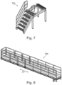
- Fig. 7 shows the stair member 50a which helps to overcome a height difference between the upper surface 11 of the barge 10 and the work platform 40 (see Fig. 2 ).
- the stair member 50a is, for example, a welded steel construction.
- Fig. 8 shows the length-adjustable platform member 50b.
- the length-adjustable platform member 50b can be adjusted in length in the lateral direction D1 for accessing the movable work platform 40 in a safe way.
- Fig. 9 shows an example of how the components of the working deck 100 are stored on the upper surface 11 of the barge 10 when the components are not in use.
- the transverse beams 20 are oriented and fixed perpendicular to the forward direction D2 of the barge 10.
- the work platform 40 equipped with the removable floor panels 40a as well as the cantilever beams 30, the link beam 60 and the gangway 50 are disposed and secured on the upper surface 11 of the barge 10 in a location reachable with a crane 90 when the barge 10 is moving to the offshore well heads 70.
- step S1 the barge 10 is positioned next to the offshore well heads 70 of the offshore well head platform and jacked-up to a height above the offshore well heads 70 in step S2 of the method 200 of Figure 15 .
- step S2 the link beam 60 is mounted between the two cantilever beams 30 in step S3 (see also Fig. 10 ).
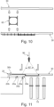
- step S4 of the method 200 of Fig. 15 and as seen in Figs. 11 and 12 the cantilever beams 30 with the link beam 60 are assembled at the transverse beams 20 using the crane 90.
- Fig. 11 shows a first part of step S4 at which the cantilever beams 30, mounted with the link beam 60 in between, are hooked and raised by the crane 90 to a position close to the transverse beams 20.
- the crane 90 can position and/or move the cantilever beams 30 with the link beam 60 along the track beams 20a and the hold-down beam 20b to change the position of the cantilever beams 30 relative to the barge 10.
- the cantilever beams 30 can be moved to a position above the well heads 70, as seen in Fig. 2 .
- the cantilever beams 30 with the link beam 60 are attached to the transverse beams 20.
- the sliders 30c are hooked to the hold-down beam 20b while the opposite side of the cantilever beams 30 is lifted.
- the opposite side of the two cantilever beams 30 is lowered and the rollers 30a are attached onto the track beam 20a.
- the cantilever beams 30 are secured with C-clamps 20c (not shown in Fig. 12 ).
- the C-clamps 20c can be affixed to the track beams 20a upfront.
- step S5 of the method 200 of Fig. 15 the work platform 40 comprising the removable floor panels 40a is positioned by the crane 90 onto the two cantilever beams 30 in such a way, that the wheels 40b of the work platform 40 are positioned on the rails 30c of the cantilever beams 30.
- the wheels 40b are driven by the electromotors 40c of the work platform 40 which are electrically connected in step S6 of the method 200 of Fig. 15 to a power supply (not shown).
- the wheels 40b are driven by at least one electromotor 40c and the work platform 40 is moved in step S7 in a lateral direction D1 to a desired horizontal working position, as shown in Figs. 2 and 14 .
- the gangway 50 can be assembled.
- step S8 of the method 200 of Fig. 15 the gangway 50 is positioned on the two cantilever beams 30 between the barge 10 and the work platform 40 (see Fig. 2 ).
- step S9 For accessing at least one of the offshore well heads 70, one or more of the removable floor panels 40a are removed in step S9 before the barge 10 is jacked-down to the desired vertical working position in step S10 of the method of Fig. 15 . It will be apparent that steps S9 and S10 can be also changed, such that step S10 is performed before step S9.
- the work platform 40 can be moved in the lateral direction D1 which also causes an adjustment of the length-adjustable platform member 50b. If needed, the barge 10 can be jacked-up/ jacked-down between different work positions during operation and or maintenance work.
- the barge 10 When the work is finished, the barge 10 is jacked-up above the well heads 70 and the components are disassembled and stored again on the upper surface 11 of the barge 10. After all components are secured the barge 10 is jacked-down and able to continue work at another offshore working location.
Landscapes
- Engineering & Computer Science (AREA)
- Mechanical Engineering (AREA)
- General Engineering & Computer Science (AREA)
- Structural Engineering (AREA)
- Civil Engineering (AREA)
- Transportation (AREA)
- Chemical & Material Sciences (AREA)
- Combustion & Propulsion (AREA)
- Ocean & Marine Engineering (AREA)
- Life Sciences & Earth Sciences (AREA)
- Geology (AREA)
- Mining & Mineral Resources (AREA)
- Environmental & Geological Engineering (AREA)
- Geochemistry & Mineralogy (AREA)
- General Life Sciences & Earth Sciences (AREA)
- Fluid Mechanics (AREA)
- Physics & Mathematics (AREA)
- Earth Drilling (AREA)
Abstract
Description
- The invention relates to working decks in general and a portable working deck to access offshore well heads in particular.
- Oil and gas well heads must be serviced and/or must be assessed for a different number of reasons. For example, valves or seals in the oil and gas well heads may need to be replaced, flanges may need to be removed or installed in the oil and gas well heads, and blowout preventers may need to be removed, added, or serviced.
- The US patent
US 6 926 097 B1 discloses an offshore jack-up workover rig for servicing of oil and gas wells. The workover rig includes a vessel which may be self-powered or powered by a tug. The vessel may be raised above the surface of a water body by extending the legs until they reach the water body bed and then continuing to extend the legs. The workover rig of this patent contains a workover floor unit which includes at least a winch, a winch motor, and a well aperture. The workover rig is detachably mounted on an extensible cantilevered frame. The frame may be extended to position the workover floor unit over an offshore platform to be serviced. The workover floor unit is also configured to mover laterally relative to the extensible frame. The vessel is also provided with a crane. The crane may be used to lift the detachable workover floor unit from the vessel and install it, including its equipment, on the platform. - Limitations regarding the structures of servicing or maintenance decks, such as conventional single deck Texas decks, are known which require a lot of the barge deck space to be utilized for rigging up/down offshore. Beams for supporting the structure are required to penetrate deep into the main deck of the barge which can cause a delay in cast off/release of the barge in case of an emergency. Shipping the conventional Texas deck into or from the barge is challenging dueto the limited space on the barges to accommodate the deck, support beams and gangway. In addition, it is difficult to access free standing offshore well heads, supported only with jacket frames at main sea level.
- The servicing of free standing well heads is carried out in some cases by drill rigs. However, the costs for hiring and operating the drill rig for the servicing is significantly high.
- It is an object of the present disclosure to provide a cost effective solution for the access and maintenance of a freestanding offshore gas and oil well head. The solution should be simple and flexible in order to be installed quickly.
- This document discloses a working deck configured to access offshore well heads, wherein the working deck comprises a barge, transverse beams fixed to an upper surface of the barge, at least two cantilever beams attachable on to the transverse beams, and a work platform positioned on the at least two cantilever beams and being movable in a lateral direction of the cantilever beams.
- In one aspect, the transverse beams are oriented perpendicular to a forward direction of the barge. This orientation of transverse beams supports the stability of the whole construction while moved to the working location and saves space on the barge.
- In another aspect, the transverse beams comprise at least one of a track beam and one of a hold-down beam for receiving the at least two cantilever beams.
- In another aspect, the at least two cantilever beams are connected with a link beam mounted between them. The link beam guarantees the stability of the cantilever beams and makes sure that the cantilever beams are oriented parallel to each other.
- In another aspect, the at least two cantilever beams further comprise rollers for rolling on the at least one track beam of the transverse beams, and further comprise sliders, for sliding along the hold-down beam of the transverse beams. The at least two cantilever beams are able to be moved along the at least one track beam and the hold down beam to change the position of the at least two cantilever beams relative to the barge.
- In another aspect, the at least one track beam further comprises C-clamps for holding a position of the at least two cantilever beams on the at least one track beam. With the C-clamps the at least two cantilever beams can be fixed relative to the at least one track beam.
- In another aspect, the work platform further comprises of removable floor panels for accessing the well heads. The floor panels can be removed as desired for an easier access of wells at different positions. Thus, the work platform itself is adjustable and more flexible for accessing the well heads.
- In another aspect, the work platform further comprises at least one wheel driven by at least one electromotor for moving the work platform on rails of the at least two cantilever beams. The work platform can, thus, be moved or re-positioned in a lateral direction along the at least two cantilever beams to access a desired horizontal working position.
- In another aspect, the working deck further comprises a gangway positioned on the at least two cantilever beams, comprising a stair member and a length-adjustable platform member.
- In another aspect, the barge further comprises a jack-up mechanism for jacking-up the barge above the well heads and for jacking-down the barge to a desired vertical working position.
- A method for accessing an offshore well heads with a working deck is also disclosed. The method comprises the steps of positioning a barge next to the offshore well head, jacking-up the barge to a height above the offshore well head, mounting a link beam between at least two cantilever beams, attaching the at least two cantilever beams to transverse beams fixed to the barge, positioning a work platform with floor panels on the at least two cantilever beams, electrically connecting at least one electromotor of the work platform, moving the work platform in a lateral direction to the at least two cantilever beams to a desired horizontal working position by using the at least one electromotor, positioning a gangway on the at least two cantilever beams between the barge and the work platform, removing of ones of the floor panels at the work platform for accessing the offshore well head, and jacking-down the barge over the offshore well heads to a desired vertical working position.
- In one aspect, the positioning of the at least two cantilever beams on the transverse beams is carried out in such a way that rollers of the at least two cantilever beams roll on at least two track beams of the transverse beams and a slider of the at least two cantilever beams slides along a hold-down beam of the transverse beams.
- In another aspect, the method further comprises fixing the at least two cantilever beams attached to the transverse beams with C-clamps.
-
-
Fig. 1 shows a working deck at an offshore working location seen from above. -
Fig. 2 shows the part of the working deck ofFig. 1 in a perspective view. -
Fig. 3 shows transverse beams of the working deck fixed to the barge. -
Fig. 4 shows at least two cantilever beams with a link beam mounted therebetween. -
Fig. 5 shows a work platform of the working deck with removed removable floor panels. -
Fig. 6 shows the work platform ofFig. 5 with attached removable floor panels. -
Fig. 7 shows a stair member. -
Fig. 8 shows a length-adjustable platform member. -
Fig. 9 shows an example of how components of the working deck are stored on the barge. -
Fig. 10 shows how the link beam is mounted between the at least two cantilever beams. -
Fig. 11 shows a first assembly step of the at least two cantilever beams with link beam at the transverse beams. -
Fig. 12 shows a second assembly step of the at least two cantilever beams with link beam at the transverse beams. -
Fig. 13 shows an assembly of a work platform. -
Fig. 14 shows the working deck in an assembled state at a first working position from above. -
Fig. 15 shows a flowchart of a method for accessing an offshore well heads with a working deck. - The invention will now be described on the basis of the drawings. It will be understood that the embodiments and aspects of the invention described herein are only examples and do not limit the protective scope of the claims in any way. The invention is defined by the claims and their equivalents. It will be understood that features of one aspect or embodiment of the invention can be combined with a feature of a different aspect or aspects and/or embodiments of the invention.
-
Fig. 1 shows a workingdeck 100 at an offshore working location as seen from above. Abarge 10 comprises jack-upmechanisms 80 forjacking-up thebarge 10 after thebarge 10 was moved to the offshore working location. The jacking-upmechanism 80 is one of a known art and will be not described in detail hereinafter. Amaintenance area 5 is located in a rear end relative to a forward direction D2 of thebarge 10. Thebarge 10 can be any of a floating vessel comprising a platform or a deck with and without its own drive. With other words, thebarge 10 can drive on its own or be drawn by another vessel, for example a boat, to the offshore working location. -
Fig. 2 shows the workingdeck 100 in operation in a perspective view. The workingdeck 100 is configured to access offshore well heads 70 of an offshore well head platform. It can be seen that the workingdeck 100 comprises in addition to thebarge 10, further components, such astransverse beams 20 with at least one of atrack beam 20a and one of a hold-down beam 20b, a plurality of stiffeningelements 25, at least twocantilever beams 30, alink beam 60, and awork platform 40. Thework platform 40 hasremovable floor panels 40a and is positioned on the cantilever beams 30. Thework platform 40 is movable in a lateral direction D1 of the cantilever beams 30. The workingdeck 100 further comprises a gangway 50 comprising astair member 50a and a length-adjustable platform member 50b. - As seen in
Fig. 3 , thetransverse beams 20 are fixed to anupper surface 11 of thebarge 10. Thetransverse beams 20 are made of a weldable metal such as for a nonlimiting example steel. Theupper surface 11 of thebarge 10 is a surface in general parallel to the surface of the water on which thebarge 10 is floating. The twotrack beams 20a and the hold-down beam 20b are fixed to theupper surface 11 of thebarge 10 by, for example, welding. - The two
track beams 20a are in the form of a rail, but this is not limiting of the invention. The twocantilever beams 30 are affixed at a desired position on thetrack beams 20a using C-clamps 20c which position the twocantilever beams 30 onto thetrack beams 20a.Fig. 3 shows a total of eight C-clamps 20c, but this is not limiting of the invention. The eight C-clamps 20c are in four pairs of two C-clamps 20c. A first two pairs are arranged on a first one of thetrack beams 20a and a second two pairs are arranged on a second one of thetrack beams 20a. The cantilever beams 30 can then be disposed and affixed between the pairs of the C-claims 20c. In this manner, the relative position of the cantilever beams 30 to thebarge 10 can be chosen and fixed before placing the two cantilever beams 30. Alternatively, the C-clamps 20c can also be affixed onto thetrack beams 20a after the cantilever beams 30 are assembled to the transverse beams 20. The C-clamps 20c are made, for example, of a metal such as steel and have the form of a letter C to cover thetrack beam 20a. The hold-down beam 20b comprises the plurality of stiffeningelements 25 which have the function of stiffening the hold-down beam 20b and to prevent or limit deformation of the hold-down beam 20b. Thestiffening elements 25 are made of a weldable metal such as steel (but this is not limiting of the invention) and are welded to the hold-down beam 20b and to theupper surface 11 of thebarge 10. - As seen in
Fig. 4 , twocantilever beams 30 are connected with alink beam 60 mounted between the two cantilever beams 30. Thelink beam 60 is for example a welded structure of metal beams which define a rigid position of the twocantilever beams 30 relative to each other. The twocantilever beams 30 haverollers 30a. Therollers 30a are designed in such a way to be able to withstand high forces and loads. It will be apparent that therollers 30a are connected to the cantilever beams 30 with bearings. Therollers 30a enable the cantilever beams 30 to roll on thetrack beams 20a. The cantilever beams 30 further havesliders 30b. Thesliders 30b enable the twocantilever beams 30 to slide along the hold-down beam 20b. Thesliders 30b are made for example of the same material as the hold-down beam 20b in order to reduce friction between thesliders 30b and the hold-down beam 20b when moved relative to each other. The twocantilever beams 30 further includerails 30c. As will be described later, thework platform 40 can be moved along therails 30c. -
Figures 5 and 6 show thework platform 40 with (Fig. 5 ) and without (Fig. 6 ) the plurality ofremovable floor panels 40a. When thework platform 40 is moved to the desired working position above the well heads 70, all or a few of theremovable floor panels 40a can be removed from thework platform 40 to access one or more of the offshore well heads 70. - The
work platform 40 further comprises at least onewheel 40b driven by at least oneelectromotor 40c. InFigs. 5 and 6 twowheels 40b are shown, but this is not limiting of the invention. The wheel/s 40b will be positioned on therails 30c of the cantilever beams 30 for moving thework platform 40 along the cantilever beams 30 in the lateral direction D1, as can be seen inFig. 1 . - In order to access the
work platform 40 in a safe way the gangway 50 (seeFig. 2 ) is positioned onto at least one of the twocantilever beams 30 between thebarge 10 and thework platform 40.Fig. 7 shows thestair member 50a which helps to overcome a height difference between theupper surface 11 of thebarge 10 and the work platform 40 (seeFig. 2 ). Thestair member 50a is, for example, a welded steel construction. -
Fig. 8 shows the length-adjustable platform member 50b. The length-adjustable platform member 50b can be adjusted in length in the lateral direction D1 for accessing themovable work platform 40 in a safe way. -
Fig. 9 shows an example of how the components of the workingdeck 100 are stored on theupper surface 11 of thebarge 10 when the components are not in use. Thetransverse beams 20 are oriented and fixed perpendicular to the forward direction D2 of thebarge 10. Thework platform 40 equipped with theremovable floor panels 40a as well as the cantilever beams 30, thelink beam 60 and the gangway 50 are disposed and secured on theupper surface 11 of thebarge 10 in a location reachable with acrane 90 when thebarge 10 is moving to the offshore well heads 70. - With reference to
Figs. 10 to 14 in conjunction withFig. 15 , amethod 200 for accessing one or a plurality of offshore well heads 70 with the workingdeck 100 will be described. - In step S1 the
barge 10 is positioned next to the offshore well heads 70 of the offshore well head platform and jacked-up to a height above the offshore well heads 70 in step S2 of themethod 200 ofFigure 15 . Following step S2 thelink beam 60 is mounted between the twocantilever beams 30 in step S3 (see alsoFig. 10 ). - In step S4 of the
method 200 ofFig. 15 and as seen inFigs. 11 and12 , the cantilever beams 30 with thelink beam 60 are assembled at thetransverse beams 20 using thecrane 90.Fig. 11 shows a first part of step S4 at which the cantilever beams 30, mounted with thelink beam 60 in between, are hooked and raised by thecrane 90 to a position close to the transverse beams 20. Thecrane 90 can position and/or move the cantilever beams 30 with thelink beam 60 along thetrack beams 20a and the hold-down beam 20b to change the position of the cantilever beams 30 relative to thebarge 10. Thus, the cantilever beams 30 can be moved to a position above the well heads 70, as seen inFig. 2 . - In a second part of step S4, as seen in
Fig. 12 , the cantilever beams 30 with thelink beam 60 are attached to the transverse beams 20. For the attachment of the cantilever beams 30, thesliders 30c are hooked to the hold-down beam 20b while the opposite side of the cantilever beams 30 is lifted. After thesliders 30c are attached to the hold-down beam 20b, the opposite side of the twocantilever beams 30 is lowered and therollers 30a are attached onto thetrack beam 20a. After the cantilever beams 30 are positioned at the desired location, the cantilever beams 30 are secured with C-clamps 20c (not shown inFig. 12 ). Alternatively, if the desired position is determined before the attachment of the cantilever beams 30 to thetransverse beams 20, the C-clamps 20c can be affixed to the track beams 20a upfront. - In step S5 of the
method 200 ofFig. 15 , as seen inFig. 13 , thework platform 40 comprising theremovable floor panels 40a is positioned by thecrane 90 onto the twocantilever beams 30 in such a way, that thewheels 40b of thework platform 40 are positioned on therails 30c of the cantilever beams 30. Thewheels 40b are driven by theelectromotors 40c of thework platform 40 which are electrically connected in step S6 of themethod 200 ofFig. 15 to a power supply (not shown). Thewheels 40b are driven by at least oneelectromotor 40c and thework platform 40 is moved in step S7 in a lateral direction D1 to a desired horizontal working position, as shown inFigs. 2 and14 . - After the
work platform 40 arrives at the desired horizontal position, the gangway 50 can be assembled. In step S8 of themethod 200 ofFig. 15 , thegangway 50 is positioned on the twocantilever beams 30 between thebarge 10 and the work platform 40 (seeFig. 2 ). - For accessing at least one of the offshore well heads 70, one or more of the
removable floor panels 40a are removed in step S9 before thebarge 10 is jacked-down to the desired vertical working position in step S10 of the method ofFig. 15 . It will be apparent that steps S9 and S10 can be also changed, such that step S10 is performed before step S9. - To access others of the offshore well heads 70 the
work platform 40 can be moved in the lateral direction D1 which also causes an adjustment of the length-adjustable platform member 50b. If needed, thebarge 10 can be jacked-up/ jacked-down between different work positions during operation and or maintenance work. - When the work is finished, the
barge 10 is jacked-up above the well heads 70 and the components are disassembled and stored again on theupper surface 11 of thebarge 10. After all components are secured thebarge 10 is jacked-down and able to continue work at another offshore working location. -
- 10
- barge
- 11
- upper surface
- 20
- transverse beams
- 20a
- track beam
- 20b
- hold-down beam
- 20c
- C-clamps
- 25
- stiffening element
- 30
- cantilever beams
- 30a
- rollers
- 30b
- sliders
- 30c
- rails
- 40
- work platform
- 40a
- removable floor panels
- 40b
- at least one wheel
- 40c
- at least one electromotor
- 50
- gangway
- 50a
- stair member
- 50b
- length-adjustable platform member
- 60
- link beam
- 70
- well head
- 80
- jack-up mechanism
- 90
- crane
- 100
- working deck
- D1
- lateral direction
- D2
- forward direction
Claims (14)
- A working deck (100) configured to access offshore well heads (70), the working deck (100) comprising:a barge (10);transverse beams (20) fixed to an upper surface (11) of the barge (10);at least two cantilever beams (30) attachable on to the transverse beams (20); anda work platform (40) positioned on the at least two cantilever beams (30) and being movable in a lateral direction (D1) of the cantilever beams (20).
- The working deck (100) of claim 1, wherein
the transverse beams (20) are oriented perpendicular to a forward direction (D2) of the barge (10). - The working deck (100) of claim 1 and 2, wherein
the transverse beams (20) comprise at least one of a track beam (20a) and one of a hold-down beam (20b). - The working deck (100) of claim 1 to 3, wherein
the at least two cantilever beams (30) are connected with a link beam (60) mounted therebetween. - The working deck (100) of claim 1 to 4, wherein
the at least two cantilever beams (30) further comprise rollers (30a) for rolling on the at least one track beam (20a) of the transverse beams (20). - The working deck (100) of claim 1 to 4, wherein
the at least two cantilever beams (30) further comprise sliders (30b), for sliding along the hold-down beam (20b) of the transverse beams (20). - The working deck (100) of claims 1 to 3, wherein
the at least one track beam (20a) further comprise C-clamps (20c) for holding a position of the at least two cantilever beams (30) on the at least one track beam (20a). - The working deck (100) of any one of the previous claims, wherein
the work platform (40) further comprises removable floor panels (40a) for accessing the well heads (70). - The working deck (100) of claim 8, wherein
the work platform (40) further comprises at least one wheel (40b) driven by at least one electromotor (40c) for moving the work platform (40) on rails (30c) of the at least two cantilever beams (30). - The working deck (100) of any one of the previous claims, further comprising
a gangway (50) positioned on the at least two cantilever beams (30), comprising a stair member (50a) and a length-adjustable platform member (50b). - The working deck (100) of any one of the previous claims, wherein
the barge (10) further comprises a jack-up mechanism (80) for jacking-up the barge (10) above the well heads (70) and for jacking-down the barge (10) to a desired vertical working position. - Method (200) for accessing offshore well heads (70) with a working deck (100), the method (200) comprising:- positioning (S1) a barge (10) next to the offshore well heads (70);- jacking-up (S2) the barge (10) to a height above the offshore well heads (70);- mounting (S3) a link beam (60) between at least two cantilever beams (30);- attaching (S4) the at least two cantilever beams (30) to transverse beams (20) fixed to the barge (10);- positioning (S5) a work platform (40) with floor panels (40a) on the at least two cantilever beams (30);- electrically connecting (S6) at least one electromotor (40c) of the work platform (40);- moving (S7) the work platform (40) in a lateral direction (D1) to the at least two cantilever beams (30) to a desired horizontal working position by using the at least one electromotor (40c);- positioning (S8) a gangway (50) on the at least two cantilever beams (30) between the barge (10) and the work platform (40);- removing (S9) of ones of the floor panels (40a) at the work platform (40) for accessing the offshore well heads (70); and- jacking-down (S10) the barge (10) over the offshore well heads (70) to a desired vertical working position.
- Method (200) of claim 11, wherein
the positioning of the at least two cantilever beams (30) on the transverse beams (20) is carried out in such a way that rollers (30a) of the at least two cantilever beams (30) roll on at least one track beam (20a) of the transverse beams (20) and a slider (30b) of the at least two cantilever beams (30) slides along a hold-down beam (20b) of the transverse beams (20). - Method (200) of claim 11, further comprising
fixing the at least two cantilever beams (30) attached to the transverse beams (20) with C-clamps (20c).
Priority Applications (2)
| Application Number | Priority Date | Filing Date | Title |
|---|---|---|---|
| EP23164203.4A EP4438814B1 (en) | 2023-03-25 | 2023-03-25 | Portable working deck |
| US18/614,648 US12680251B2 (en) | 2023-03-25 | 2024-03-23 | Portable working deck |
Applications Claiming Priority (1)
| Application Number | Priority Date | Filing Date | Title |
|---|---|---|---|
| EP23164203.4A EP4438814B1 (en) | 2023-03-25 | 2023-03-25 | Portable working deck |
Publications (3)
| Publication Number | Publication Date |
|---|---|
| EP4438814A1 true EP4438814A1 (en) | 2024-10-02 |
| EP4438814B1 EP4438814B1 (en) | 2026-02-18 |
| EP4438814C0 EP4438814C0 (en) | 2026-02-18 |
Family
ID=85775901
Family Applications (1)
| Application Number | Title | Priority Date | Filing Date |
|---|---|---|---|
| EP23164203.4A Active EP4438814B1 (en) | 2023-03-25 | 2023-03-25 | Portable working deck |
Country Status (2)
| Country | Link |
|---|---|
| US (1) | US12680251B2 (en) |
| EP (1) | EP4438814B1 (en) |
Citations (4)
| Publication number | Priority date | Publication date | Assignee | Title |
|---|---|---|---|---|
| US6926097B1 (en) | 2002-03-06 | 2005-08-09 | Michael E. Blake | Jack up workover rig with removable workover floor unit |
| US6932553B1 (en) * | 2003-03-17 | 2005-08-23 | Itrec, B.V. | Multipurpose unit for drilling and well intervention |
| US8566992B1 (en) * | 2010-05-10 | 2013-10-29 | Patrick Stokes | Extendable and retractable work platform |
| NO20171677A1 (en) * | 2017-03-30 | 2018-10-01 | Dwellop As | Cantilever structure with a hoist crane assembly |
Family Cites Families (7)
| Publication number | Priority date | Publication date | Assignee | Title |
|---|---|---|---|---|
| US4483644A (en) * | 1982-09-15 | 1984-11-20 | Johnson Thomas P | Cantilevered mobile marine rig with hydraulic load equalizer |
| US5042612A (en) * | 1990-06-15 | 1991-08-27 | Aluminum Ladder Company | Bulk material load vehicle access system |
| EP0468424B1 (en) * | 1990-07-24 | 1995-07-12 | i f m electronic gmbh | Electronic switching apparatus with presence indicator |
| US20120006618A1 (en) * | 2010-07-07 | 2012-01-12 | Aluminium Ladder Company | Cement industry gangway and safety cage |
| NL2008920C2 (en) * | 2012-06-01 | 2013-12-04 | Knowledge B V Z | Vessel provided with a gangway supported by a 2-dof hinged upright column, in particular a cardan. |
| US9260920B2 (en) * | 2013-03-15 | 2016-02-16 | Offshore Technology Development | Multipurpose cantilever skidding frame |
| NO341926B1 (en) * | 2016-06-15 | 2018-02-19 | Kystvaagen Slip & Mek As | Walkway for transferring personnel and equipment from a first facility to a second facility |
-
2023
- 2023-03-25 EP EP23164203.4A patent/EP4438814B1/en active Active
-
2024
- 2024-03-23 US US18/614,648 patent/US12680251B2/en active Active
Patent Citations (4)
| Publication number | Priority date | Publication date | Assignee | Title |
|---|---|---|---|---|
| US6926097B1 (en) | 2002-03-06 | 2005-08-09 | Michael E. Blake | Jack up workover rig with removable workover floor unit |
| US6932553B1 (en) * | 2003-03-17 | 2005-08-23 | Itrec, B.V. | Multipurpose unit for drilling and well intervention |
| US8566992B1 (en) * | 2010-05-10 | 2013-10-29 | Patrick Stokes | Extendable and retractable work platform |
| NO20171677A1 (en) * | 2017-03-30 | 2018-10-01 | Dwellop As | Cantilever structure with a hoist crane assembly |
Also Published As
| Publication number | Publication date |
|---|---|
| EP4438814B1 (en) | 2026-02-18 |
| US20240318395A1 (en) | 2024-09-26 |
| US12680251B2 (en) | 2026-07-14 |
| EP4438814C0 (en) | 2026-02-18 |
Similar Documents
| Publication | Publication Date | Title |
|---|---|---|
| JP3908282B2 (en) | Jack-up platform locking device | |
| CN103847930B (en) | offshore drilling vessel | |
| US5997217A (en) | Shallow water well-drilling apparatus | |
| US9458671B2 (en) | Method and apparatus for drilling multiple subsea wells from an offshore platform at a single site | |
| EP2167781B1 (en) | Well apparatus | |
| EP1583884B1 (en) | An offshore drilling system | |
| EP1021624B1 (en) | Method and apparatus for the offshore installation of multi-ton packages such as deck packages and jackets | |
| US4063650A (en) | Equipment handling system | |
| EP2681400B1 (en) | A cantilever system and method of use | |
| US4203576A (en) | Elevating assembly for an offshore platform | |
| US20210032945A1 (en) | Drilling installation: handling system, method for independent operations | |
| EP0643787B1 (en) | Method and apparatus for transporting and using a drilling apparatus or a crane apparatus from a single movable vessel | |
| EP2692630A1 (en) | Elevation-type thruster apparatus | |
| GB2165188A (en) | Installation and removal vessel | |
| MXPA06003907A (en) | Extensible semi-submersible platform. | |
| EP3710351B1 (en) | Vessel and method for performing subsea wellbore related activities | |
| US6203247B1 (en) | Drilling vessel with moveable substructure | |
| KR20140035488A (en) | Deck arrangement on a vessel or platform for performing subsea operations | |
| KR102940417B1 (en) | Raising and lowering of the ship lift platform | |
| CN110998028B (en) | Seaworthiness fixation of a cantilever on a mobile offshore platform | |
| EP0345947B1 (en) | An offshore drilling/production platform with a retractable work deck | |
| EP4438814B1 (en) | Portable working deck | |
| CN212313805U (en) | Marine springboard ladder | |
| US6718902B1 (en) | Walkways for platforms on offshore marine structures | |
| GB2116236A (en) | Improvements relating to oil platforms and rigs |
Legal Events
| Date | Code | Title | Description |
|---|---|---|---|
| PUAI | Public reference made under article 153(3) epc to a published international application that has entered the european phase |
Free format text: ORIGINAL CODE: 0009012 |
|
| STAA | Information on the status of an ep patent application or granted ep patent |
Free format text: STATUS: REQUEST FOR EXAMINATION WAS MADE |
|
| 17P | Request for examination filed |
Effective date: 20240327 |
|
| AK | Designated contracting states |
Kind code of ref document: A1 Designated state(s): AL AT BE BG CH CY CZ DE DK EE ES FI FR GB GR HR HU IE IS IT LI LT LU LV MC ME MK MT NL NO PL PT RO RS SE SI SK SM TR |
|
| REG | Reference to a national code |
Ref legal event code: R079 Ipc: B63B0035280000 Ref country code: DE Ref legal event code: R079 Ref document number: 602023012042 Country of ref document: DE Free format text: PREVIOUS MAIN CLASS: E02B0017000000 Ipc: B63B0035280000 |
|
| GRAP | Despatch of communication of intention to grant a patent |
Free format text: ORIGINAL CODE: EPIDOSNIGR1 |
|
| STAA | Information on the status of an ep patent application or granted ep patent |
Free format text: STATUS: GRANT OF PATENT IS INTENDED |
|
| RIC1 | Information provided on ipc code assigned before grant |
Ipc: B63B 35/28 20060101AFI20250827BHEP Ipc: E02B 17/00 20060101ALI20250827BHEP Ipc: E21B 15/00 20060101ALI20250827BHEP Ipc: B63B 35/00 20200101ALI20250827BHEP Ipc: B63B 3/48 20060101ALI20250827BHEP |
|
| INTG | Intention to grant announced |
Effective date: 20250915 |
|
| GRAS | Grant fee paid |
Free format text: ORIGINAL CODE: EPIDOSNIGR3 |
|
| GRAA | (expected) grant |
Free format text: ORIGINAL CODE: 0009210 |
|
| STAA | Information on the status of an ep patent application or granted ep patent |
Free format text: STATUS: THE PATENT HAS BEEN GRANTED |
|
| AK | Designated contracting states |
Kind code of ref document: B1 Designated state(s): AL AT BE BG CH CY CZ DE DK EE ES FI FR GB GR HR HU IE IS IT LI LT LU LV MC ME MK MT NL NO PL PT RO RS SE SI SK SM TR |
|
| REG | Reference to a national code |
Ref country code: CH Ref legal event code: F10 Free format text: ST27 STATUS EVENT CODE: U-0-0-F10-F00 (AS PROVIDED BY THE NATIONAL OFFICE) Effective date: 20260218 Ref country code: GB Ref legal event code: FG4D |
|
| REG | Reference to a national code |
Ref country code: IE Ref legal event code: FG4D |
|
| REG | Reference to a national code |
Ref country code: DE Ref legal event code: R096 Ref document number: 602023012042 Country of ref document: DE |
|
| PGFP | Annual fee paid to national office [announced via postgrant information from national office to epo] |
Ref country code: AT Payment date: 20260301 Year of fee payment: 4 |
|
| U01 | Request for unitary effect filed |
Effective date: 20260312 |
|
| U07 | Unitary effect registered |
Designated state(s): AT BE BG DE DK EE FI FR IT LT LU LV MT NL PT RO SE SI Effective date: 20260317 |
|
| U20 | Renewal fee for the european patent with unitary effect paid |
Year of fee payment: 4 Effective date: 20260322 |
|
| PG25 | Lapsed in a contracting state [announced via postgrant information from national office to epo] |
Ref country code: RS Free format text: LAPSE BECAUSE OF FAILURE TO SUBMIT A TRANSLATION OF THE DESCRIPTION OR TO PAY THE FEE WITHIN THE PRESCRIBED TIME-LIMIT Effective date: 20260518 |
|
| PG25 | Lapsed in a contracting state [announced via postgrant information from national office to epo] |
Ref country code: ES Free format text: LAPSE BECAUSE OF FAILURE TO SUBMIT A TRANSLATION OF THE DESCRIPTION OR TO PAY THE FEE WITHIN THE PRESCRIBED TIME-LIMIT Effective date: 20260218 |
|
| PG25 | Lapsed in a contracting state [announced via postgrant information from national office to epo] |
Ref country code: PL Free format text: LAPSE BECAUSE OF FAILURE TO SUBMIT A TRANSLATION OF THE DESCRIPTION OR TO PAY THE FEE WITHIN THE PRESCRIBED TIME-LIMIT Effective date: 20260218 |
|
| PG25 | Lapsed in a contracting state [announced via postgrant information from national office to epo] |
Ref country code: GR Free format text: LAPSE BECAUSE OF FAILURE TO SUBMIT A TRANSLATION OF THE DESCRIPTION OR TO PAY THE FEE WITHIN THE PRESCRIBED TIME-LIMIT Effective date: 20260519 |
|
| PG25 | Lapsed in a contracting state [announced via postgrant information from national office to epo] |
Ref country code: NO Free format text: LAPSE BECAUSE OF FAILURE TO SUBMIT A TRANSLATION OF THE DESCRIPTION OR TO PAY THE FEE WITHIN THE PRESCRIBED TIME-LIMIT Effective date: 20260518 |
|
| PG25 | Lapsed in a contracting state [announced via postgrant information from national office to epo] |
Ref country code: HR Free format text: LAPSE BECAUSE OF FAILURE TO SUBMIT A TRANSLATION OF THE DESCRIPTION OR TO PAY THE FEE WITHIN THE PRESCRIBED TIME-LIMIT Effective date: 20260218 |
|
| PG25 | Lapsed in a contracting state [announced via postgrant information from national office to epo] |
Ref country code: IS Free format text: LAPSE BECAUSE OF FAILURE TO SUBMIT A TRANSLATION OF THE DESCRIPTION OR TO PAY THE FEE WITHIN THE PRESCRIBED TIME-LIMIT Effective date: 20260618 |