EP4438800A1 - A drying air filter for a laundry dryer - Google Patents
A drying air filter for a laundry dryer Download PDFInfo
- Publication number
- EP4438800A1 EP4438800A1 EP23165207.4A EP23165207A EP4438800A1 EP 4438800 A1 EP4438800 A1 EP 4438800A1 EP 23165207 A EP23165207 A EP 23165207A EP 4438800 A1 EP4438800 A1 EP 4438800A1
- Authority
- EP
- European Patent Office
- Prior art keywords
- supporting
- grid
- propping
- filter
- drying air
- Prior art date
- Legal status (The legal status is an assumption and is not a legal conclusion. Google has not performed a legal analysis and makes no representation as to the accuracy of the status listed.)
- Granted
Links
Images




Classifications
-
- D—TEXTILES; PAPER
- D06—TREATMENT OF TEXTILES OR THE LIKE; LAUNDERING; FLEXIBLE MATERIALS NOT OTHERWISE PROVIDED FOR
- D06F—LAUNDERING, DRYING, IRONING, PRESSING OR FOLDING TEXTILE ARTICLES
- D06F58/00—Domestic laundry dryers
- D06F58/20—General details of domestic laundry dryers
- D06F58/22—Lint collecting arrangements
Definitions
- the present invention relates to a drying air filter for a laundry dryer. Further, the present invention relates to a laundry dryer comprising a drying air filter.
- a drying air filter is provided for collecting foreign particles, in particular fluff or lint occurring or generated when the laundry is treated by a hot air stream.
- the laundry is usually inside a rotating laundry drum and the air stream from the laundry drum passes through the drying air filter and the foreign particles are filtered out by the drying air filter and the air stream leaves the drying air filter substantially free from foreign particles and may enter another component of the dryer depending on the type of dryer, the component being for instance a heat exchanger in a condenser dryer or a heat pump in a heat pump dryer or also an exhaust in an open loop.
- the drying air filter usually comprises a filter mesh (or: filter net or filter fabric), which is held by a filter frame or support.
- the drying air filter may be arranged within a door or the frame surrounding the door or within a base below the drum and is mounted in an easily accessible and cleanable manner to remove the fluff or lint.
- the user can at least partially demount or detach the filter, in particular by pulling the filter out from its seat or unfolding it or removing it completely.
- the lint or fluff may be removed or disposed of in a filter cleaning procedure by means of the user's fingers or an external tool for scratching the fluff or lint off the surface of the filter mesh.
- the filter mesh and even the filter frame may be damaged during the cleaning procedure by the external tool.
- the drying air filter may be damaged during removing from and inserting into the laundry dryer.
- WO 2018/121869 A1 discloses a filter assembly in a laundry dryer positioned at least partially in a duct defining a flow passage for process air exiting the drum, so as to filter process air flowing in the duct, and preferably below the drum at the rim of the aperture.
- the filter assembly includes a frame defining a storage portion and a filter mesh with a filtering surface supported by a matrix-like support structure with orthogonally crossing webs or ribs of the frame.
- the filter assembly includes a substantially wedge-shaped filtering cartridge or shell in a frame.
- the shell includes a first part with a filter mesh and a second part with a filter mesh, the first part and the second part of the shell being hinged to each other.
- a cleaning device for cleaning the filtering surface is provided including a translatable wiper with a handle to wipe the filtering surface during translating. The filtered material wiped off the filtering surface by the wiper is collected in the storage portion.
- WO 2018/121871 A1 discloses a filter assembly in a laundry dryer positioned at least partially in a duct defining a flow passage for process air exiting the drum, so as to filter process air flowing in the duct, and preferably below the drum at the rim of the aperture.
- the filter assembly includes a frame and a filter mesh with a filtering surface supported by a semi-circular grid-like support structure with radially and circumferentially crossing webs or ribs of the frame.
- a cleaning device for cleaning the filtering surface is provided including a wiper to wipe the filtering surface, said wiper being positioned in a wiper seat, and a manually operable handle connected to the wiper.
- the cleaning device is pivotably attached to the frame, so as to rotate around an axis to wipe the filtering surface.
- WO 2018/121872 A1 discloses a filter assembly in a laundry dryer positioned at least partially in a duct defining a flow passage for process air exiting the drum, so as to filter process air flowing in the duct, and preferably below the drum at the rim of the aperture.
- the filter assembly includes a frame and a filter mesh with a filtering surface supported by the frame.
- a cleaning device for cleaning the filtering surface is provided including a roto-translatable wiper having a handle to wipe the filtering surface during translating.
- the wiper is connected by means of a pin-guide connection to a portion of said frame to allowing a portion of the wiper to perform a rotational and translational movement with respect to said frame.
- drying air filter shall in particular allow a reliable cleaning of the filter mesh using a cleaning tool, even without having to demount the drying air filter from the laundry dryer.
- the drying air filter according to claim 1 is provided for a laundry dryer and comprises
- the drying air filter further comprises
- the propping grid stabilizes the supporting grid against deformation by a cleaning tool or a hand cleaning the filter mesh and, nevertheless, a decrease in drying air flow through the filter is kept low.
- At least one or several of the propping ribs of the at least one propping grid crosses or cross at least one or several of the at least one supporting rib of the at least one supporting grid at at least one respective crossing point, seen from the direction of the drying air, and at least one or each contact portion is arranged at a corresponding crossing points.
- the first inner part has a first inner frame forming a first inner air passage and the second inner part has a second inner frame forming a second inner air passage, the inner shell being arranged such that, in a closed or mounted state of the drying air filter, the first inner frame and the second inner frame engage with each other to form the inner shell, the first supporting grid being connected to or being a part of the first inner frame, extending across the first inner air passage, the second supporting grid being connected to or being a part of the second inner frame, extending across the second inner air passage.
- the first inner air passage may correspond to the air passage area for a first stream of drying air.
- the second inner air passage may correspond to the air passage area for a second stream of drying air.
- the two supporting grids of the two inner parts may be configured to be mirror-symmetrical to each other and/or congruent and/or the two propping grids of the two outer parts may be configured to be mirror-symmetrical to each other and/or congruent.
- the shape of the supporting ribs and/or the propping ribs at least some or most or all them may be linear or straight, although some of the ribs may also be curved, and/or at least some or all of the supporting ribs and/or the propping ribs have a circular or a polygonal or an elongated streamlined cross-section.
- the or each supporting grid and/or the or each propping grid is composed of several grid cells formed by the grid openings and the adjacent or partially surrounding grid ribs and optionally also border ribs or rims.
- at least two of the grid cells of one or each of the grids differ from each other in size and/or shape, thus forming in particular an irregular grid.
- at least a majority of the grid cells of the supporting grid and/or of the propping grid are of polygonal shape, preferably at least two or three different polygonal shapes, including in particular trigonal shapes, quadrilateral shapes and pentagonal shapes.
- the grid cell pattern of the supporting grid differs, in a preferred embodiment, from the grid cell pattern of the propping grid in at least one of the number, the shape and the size of the grid cells.
- the drying air filter further comprising a cleaning tool for cleaning, in particular wiping or scraping, the or each filter mesh in a cleaning movement across the mesh surface, in particular to remove lint or fluff from the mesh.
- the cleaning movement may be a rotatory or pivoting movement about a rotational axis or a translational or a combination of rotatory and translational movement.
- the cleaning tool may comprise a handle for manually moving the cleaning tool.
- the cleaning tool is in particular arranged, at least partly, in an intermediate space between the first inner part and the second inner part and/or between the two filter meshes for simultaneously cleaning both filter meshes.
- the at least one contact portion is arranged within an inner area of the air passage area defined by the support grid openings of at least one supporting grid, wherein the inner area within one third and two thirds of the air passage area.
- the inner area preferably extends within one fourth and three fourths, preferably between one third and two thirds, of at least one diameter of the air passage area.
- the majority of the at least one contact portion is arranged within the inner area.
- the at least one contact portion is arranged within the inner area.
- the at least one filter mesh and the corresponding at least one supporting grid supporting the at least one filter mesh may form separate parts, in particular may be independently produced, or also may form an integral part or single-piece, in particular may be formed integrally in one production process.
- the at least one filter mesh is arranged on a first side, preferably a first outer side, of the at least one supporting rib of the supporting grid and the at least one propping rib props up the respective at least one supporting rib at a second side, preferably a second outer side, opposite to the first side, of the at least one supporting rib.
- the filter mesh is supported, at least partially, on an outer side of the supporting grid or supporting rib(s).
- the at least one filter mesh is, at least partially, offset (or: displaced, recessed) from an outer side of the supporting grid, and/or arranged inside the supporting grid opening(s) and preferably supported at its respective edge by the supporting rib(s), in particular by a respective side section of the supporting rib(s) delimiting the respective supporting grid opening.
- the at least one propping grid or propping rib is arranged downstream of the at least one supporting grid, seen from the direction of the drying air.
- the at least one propping grid may preferably be arranged on an outer side of the at least one supporting grid.
- the invention in a further embodiment also relates to a laundry dryer comprising at least one drying air filter according to an embodiment of the invention for filtering the drying air used or having been used for drying laundry.
- the drying air filter is preferably detachably arranged in a seat of an opening frame of the dryer.
- FIG 1 illustrates, in a schematic perspective view, an embodiment with one mesh supporting grid and one propping grid during mounting
- FIG 2 illustrates, in a schematic perspective view, the embodiment of FIG 1 with the two grids in a mounted state with two contact portions.
- the drying air filter comprises:
- fluff and other foreign material will be collected on the upstream side of the filter mesh 3 or 6.
- the user may access the filter, with for example a fingers or a cleaning tool, from the upstream side of the filter mesh 3 or 6 and apply a force on the filter mesh 3 or 6 and the supporting grid 2 or 5 in the downstream direction.
- the propping grid 4 or 7 is propping up the supporting grid 2 or 5 and the filter mesh 3 or 6, from the downstream side of the filter mesh 3, such that the supporting grid 2 or 5 and the filter mesh 3 or 6 are less deformed during cleaning of the filter.
- a supporting grid 2 with a mesh 3 having a semi-circular border rib 17 and two interior linear supporting ribs 8 forming a V inside the border rib 17 is placed onto a propping grid 4 having a semi-circular border rib 19 and a concentric propping rib 9 and a linear central propping rib 9.
- supporting grid openings are formed within the supporting grid 2, separated from each other by the supporting ribs 8 and which define an air passage area for passing through of the drying air A.
- propping grid openings are formed within the propping grid 4, separated from each other by the propping ribs 9. The propping grid openings are at least partially provided for passing through of the drying air A.
- two crossing points XA and XB are formed between the supporting ribs 8 and the propping ribs 9 (in this case the semi-circular propping rib 9), wherein at each of the two crossing points XA and XB is a contact portion XA and XB provided for propping up the support grid 2 by the propping grid 4.
- the contact portions XA and XB are arranged at the respective crossing points between the supporting ribs 8 and the propping ribs 9.
- the angle between the crossing propping rib 9 and the supporting rib 8 could be about 60° to 90°, preferably about 90°.
- the inner frame 17, forming the air passage area is semi-circular and thus the inner area can be defined based on a radius from the point where the two supporting ribs 8 coincide to the circular part of the inner frame 17.
- the contact portions XA and XB are arranged within an inner area of the semi-circular air passage extending between one fourth and three fourths of the radius of the semi-circular air passage.
- the contact portions XA and XB are arranged within an inner area of the semi-circular air passage extending between one third and two thirds of the radius of the semi-circular air passage.
- drying air filter comprises an inner part and an outer part.
- the inner part may comprise:
- the outer part may comprise:
- Each of the propping ribs 9 is crossing one of the supporting ribs 8 at a respective crossing point XA and XB.
- the propping grid 4 may in this case correspond to the propping ribs 9.
- the propping grid 4 may correspond to the propping ribs 9 and the outer frame 19.
- FIG 3 illustrates, in a schematic perspective view, an embodiment with one mesh supporting grid and one propping grid during mounting
- FIG 4 illustrates, in a schematic perspective view, the embodiment of FIG 3 with the two grids in a mounted state with two contact portions.
- the drying air filter comprises:
- a supporting grid 5 with a mesh 6 having a rectangular border rib 21 and a linear central supporting rib 11 is placed onto a propping grid 7 having a rectangular border rib 23 and a linear central propping rib 13.
- supporting grid openings are formed within the supporting grid 5, separated from each other by the supporting rib 11 and which define an air passage area for passing through of the drying air A.
- propping grid openings are formed within the propping grid 7, separated from each other by the propping rib 13. The propping grid openings are at least partially provided for passing through of the drying air A.
- a crossing point XC which in this case is also a contact portion XC, is formed between the supporting rib 11 and the propping rib 13, for propping up the support grid 2 by the propping grid 4.
- the angle between the crossing ribs 11 and 13 is preferably 90°.
- This rectangular embodiment is suitable for a linearly displaceable cleaning tool (further explained below).
- the direction of the drying air is indicated by the arrow A in FIG 4 .
- the propping grid 7 is arranged downstream of the supporting grid 5, seen from the direction of the drying air A.
- an inner part of the filter comprises the supporting grid 5.
- the border rib 21 may be an inner frame 21, such that the supporting grid 5 is connected to or is a part of the inner frame 21.
- an outer part of the filter may comprise the propping grid 7.
- the border rib 23 may be an outer frame 23, such that the propping grid 7 is connected to or is a part of the inner frame 21.
- drying air filter comprises an inner part and an outer part.
- the inner part may comprise:
- the supporting grid 5 may in this case correspond to the supporting rib 11.
- the supporting grid 5 may correspond to the supporting rib 11 and the inner frame 21.
- the outer part may comprise:
- the propping grid 7 may in this case correspond to the propping rib 13.
- the propping grid 7 may correspond to the propping rib 13 and the outer frame 23.
- a contact portion XC is arranged at the crossing point between the supporting rib 11 and the propping rib 13. In this case the contact portion XC is arranged in the middle of the air passage area.
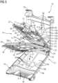
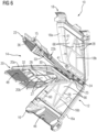
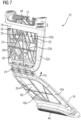
- FIG 5 to 7 each illustrate a schematic perspective view of a drying air filter 10 for a laundry dryer 50 (shown in FIG 12 ) according to a preferred embodiment of the present invention.
- the drying air filter 10 is in an opened or demounted state.
- the drying air filter 10 comprises an outer shell 12 and an inner shell 14.
- the outer shell 12 includes a first outer part 16 and a second outer part 18 which are hinged to each other by means of a hinge 24 and can be moved about that hinge 24 in a pivoting movement P3.
- the inner shell 14 includes a first inner part 20 comprising an inner frame 20a and a mesh supporting grid 20b having supporting ribs 34 supporting a filter mesh 32, and further includes a second inner part 22 comprising an inner frame 22a and a mesh supporting grid 22b having supporting ribs 35 supporting another filter mesh 33. Thereby an intermediate space is formed within the inner shell between the first inner part and the second inner part.
- the first inner part 20 and the second inner part 22 of the inner shell 14 may be hinged to each other by means of a hinge 25 and can be moved about that hinge 25 in a pivoting movement P2.
- Other means to connect the first inner part 20 and the second inner part 22 are possible too.
- the inner shell 14 and the outer shell 12 are removably and pivotably connected with each other by means of a rotatable, preferably snapping or clipping, connection of the hinge 25 of the inner shell 14 at the two ends into two respective, in particular sleeve-like or hollow pin like, hinge bearings 41 at the outer shell 12, in particular at the second outer part 18.
- a rotatable, preferably snapping or clipping connection of the hinge 25 of the inner shell 14 at the two ends into two respective, in particular sleeve-like or hollow pin like, hinge bearings 41 at the outer shell 12, in particular at the second outer part 18.
- Other means to connect the inner shell 14 and the outer shell 12 are possible too.
- outer shell 12 and the inner shell 14 can be opened separately by their respective pivoting movements P2 and P3 and they can be pivoted with respect to each other by a pivoting movement P1, a high degree of freedom of motion for cleaning of the filter meshes 32 and 33 and the intermediate space between the two filter meshes 32 and 33 from fluff or lint is achieved.
- the first inner frame 20a of the first inner part 20 as well as the second inner frame 22a of the second inner part 22 each define the boundary of an air passage for the drying air and each surround the corresponding first mesh supporting grid 20b or second mesh supporting grid 22b, so that each mesh supporting grid 20b and 22b with the corresponding mesh 32 or 33 extends across the whole area of the air passage for the respective stream of drying air.
- the supporting grid 20b or 22b with the respective filter mesh 32 and 33 are arranged within an air passage for the drying air.
- the first outer part 16 and the first inner part 20 are arranged substantially parallel to each other and the second inner part 22 and the second outer part 18 are arranged substantially parallel to each other and the two inner parts 20 and 22 of the inner shell 14 may be (slightly) inclined to each other or also be arranged parallel to each other.
- the different parts, typically the two outer parts 16 and 18 of the filter 10 are preferably connected with each other in the closed state, for instance by snapping or clipping means.
- a filter handle 15 is provided for handling the filter 10, in particular pulling the filter 10 out of its seat 90 if needed.
- drying air A of the laundry dryer 50 In the closed state of the filter 10 and when the filter 10 is mounted into its seat 90 in the laundry dryer 50, drying air A of the laundry dryer 50, typically moistured drying air A coming from the drum 52 (see FIG 12 ), passes into or is guided into the intermediate space between the filter meshes 32 and 33.
- the first outer part 16 comprises a perforated inlet plate 46 at its frame 16a and the first inner part 20 comprises a slotted inlet grid 48 at its frame 20a for forming, in the closed state of the filter 10, an inlet passage for the drying air A into the filter 10 and the intermediate space between the two filter meshes 32 and 33.
- the drying air A then passes or flows from this intermediate space through the two flow paths or passages each constituted by the corresponding filter mesh 32 or 33, the corresponding supporting grid 20b or 22b and the corresponding propping grid 16b or 18b, which may be connected in series aerodynamically or regarding the air flow, i.e. from the intermediate space inside of the inner shell 14 through the inner shell 14 and the outer shell 12 outwardly to the outside of the outer shell 12.
- the filtered drying air exiting the filter 10 is then guided to a different space inside the laundry dryer 50 for further processing such as either removal of moisture by means of a heat exchanger or heat pump and heating up the air again and returning it as fresh drying air into the drum, or simply for direct discharge into the environment.
- This flow of the drying air A is indicated in FIG 5 by respective arrows.
- the first propping grid 16b is arranged downstream of the first supporting grid 20b, seen from the direction of the drying air A.
- the second propping grid 18b is arranged downstream of the second supporting grid 22b, seen from the direction of the drying air A.
- the filter mesh 32 may be arranged upstream of the supporting ribs 34 and/or the first supporting grid 20b, seen from the direction of the drying air A, resting against, or being fixed to, the supporting ribs 34 and/or the mesh supporting grid 20b.
- the filter mesh 33 may be arranged upstream of the supporting ribs 35 and/or the mesh supporting grid 22b, resting against, or being fixed to, the supporting ribs 35 and/or the mesh supporting grid 22b.
- the filter mesh 32 is at least partly integrally arranged with the supporting ribs 34 and/or the mesh supporting grid 20b, such that filter mesh 32 is at least partly extending through the supporting ribs 34 and/or the mesh supporting grid 20b. That is, seen from the direction of the drying air A, the supporting ribs 34 and/or the mesh supporting grid 20b, may be arranged on the upstream side and the downstream side of the filter mesh 32 and firmly holding the filter mesh.
- the filter mesh 33 is integrally arranged with the supporting ribs 35 and/or the second mesh supporting grid 22b.
- the at least one supporting grid 20b or 22b may be formed as a single-piece part, for instance as injection moulded plastic part.
- the filter mesh 32 or 33 may be clamped between a first mould part with cavities forming the respective supporting ribs 34 or 35 of the supporting grid 20b or 22b and a second mould with or without corresponding cavities forming the respective supporting ribs 34 or 35 of the supporting grid 20b or 22b.
- molten plastic introduced in the first mould part may, at least partly, pass through the filter mesh 32 or 33 to the second mould part, thereby forming a rigid connection between the respective supporting ribs 34 or 35 of the supporting grid 20b or 22b and the filter mesh 32 or 33.
- a significant part of the filtered particles or residue such as fluff or flint stays, however, on the inner surfaces of the filter meshes 32 and 33 and sticks thereto. Therefore, a mechanical cleaning, such as scraping or wiping off, of the filter meshes 32 and 33, for removal of the filtered polluting material such as fluff or lint, sticking to the surfaces of the filter meshes 32 and 33, is needed or at least beneficial at regular intervals after operation of the dryer to not obstruct the flow of air by the polluted filter meshes 32 and 33.
- This cleaning action or removal of the fluff or lint sticking to the surfaces of the filter meshes 32 and 33, which are opposing each other, may, in one embodiment of the invention, be achieved in a conventional way by dismounting or detaching the filter 10 from its seat 90 in the laundry dryer 50 and opening the outer shell 12 and then the inner shell 14 of the filter 10 as to make the filter meshes 32 and 33 accessible and using the fingers or a tool for scratching the dirt layer or sticking fluff or lint off the filter meshes 32 and 33.
- a cleaning tool (or scratching tool, wiper, scraper) 36 is associated with or contained by the drying filter 10, preferably arranged, in particular removably arranged, within the inner shell 14 (in the closed state of the filter 10).
- the cleaning tool 36 is shown attached to the inner part 22 of the inner shell 14 in a resting state in FIGs 5 and 6 and in a detached state in more detail in FIG 8 .
- the cleaning tool 36 can be moved across at least one, preferably both, of the filter meshes 32 and 33 in a cleaning movement parallel to the mesh surface.
- the cleaning tool 36 has two cleaning (or: scratching, wiping) contours 37 at opposite sides.
- Each cleaning contour 37 in the closed state of the drying air filter 10, swipes or glides across the surface of the corresponding filter mesh 32 and 33 during the cleaning movement in forward and backward direction, so that during the cleaning movement the cleaning tool 36 with its cleaning contours 37 cleans the surfaces of both filter meshes 32 and 33 simultaneously, thereby removing fluff and lint, in general foreign particles, from the filter meshes 32 and 33 at the same time.
- the cleaning movement is a rotating (or: pivoting) movement about an axis of rotation defined by an axle 42 arranged at the inner part 22 or inner shell 14, wherein the cleaning tool 36 is formed as a two-arm lever rotatably attached to the axle 42 by means of an axle bearing 39.
- the lever part with the cleaning contours 37 is arranged on one side of the axle bearing 39, and on the other side the cleaning tool 36 comprises a tool handle 38 for gripping and actuating the cleaning tool 36 in the cleaning movement is arranged.
- the axle 42 is, in the closed state of the inner shell 14, received and stabilized by an axle counterpart 44 at the other inner part 20 of the inner shell 14.
- the area to be cleaned by the cleaning tool 36 is, therefore, a circular sector with the axle 42 defining the centre and the radial length of the cleaning contour 37 basically defining the radius of the circular sector.
- This circular sector preferably corresponds to the air passage for the drying air.
- the circular sector area to be cleaned is, thus, also defined and matched by the supporting grids 20b and 22b both of which comprising or are connected to a circular arc shaped border rib 30 or 31 of the inner frame 20a or 22a having the axle 42 as the centre in the closed state and having a radius adapted to the radial length of the cleaning tool 36 or its cleaning contour 37 and the supporting ribs 34 or 35 arranged within (see for instance FIG 11 ).
- the respective air passage area is the area the cleaning tool 36 is configured to clean.
- the border rib 30 of the first inner part 20 and the border rib 31 of the second inner part 22 are connected to each other in an airtight way, such that the drying air A coming from the drum 52, guided into the intermediate space between the filter meshes 32 and 33, only can exit the filter 10 through the respective air passage area of the respective filter meshes 32 and 33, as explained above.
- a rigid connection is obtained between the first inner part 20 and the second inner part 22, along the border ribs 30 and 31 and at the point of the axle 42 and the counterpart of the axle 44.
- the border ribs 30 and 31 may also act as guide rails or surfaces for the cleaning tool 36 to assist the cleaning movement of the cleaning tool 36.
- the circular sector area surrounded or delimited by the border rib 30 or 31 of the inner frame 20a or 22a and by a preferably linear, inner rim 70 or 71 of the inner frame 20a or 22a may be semi-circular or have an opening angle of about 180°, but may also have a smaller or larger opening angle.
- the air passage area may have another shape than semi-circular.
- the air passage area may be polygonal.
- the air passage area may be rectangular, as illustrated in FIG 3 and FIG 4 .
- FIG 10 depicts an embodiment of the supporting grids 20b and 22b and the inner shell 14 in more detail.
- the two supporting grids 20b and 22b of the inner parts 20 and 22 may be configured to be mirror-symmetrical to each other and/or congruent when pivoted towards each other about the hinge 25 in the closed state, but may also be not symmetrical to each other.
- Each supporting grid 20b and 22b comprises the arc shaped border rib 30 or 31 enclosing a circular sector supporting area with a plurality of preferably linear or straight supporting ribs 34 or 35 supporting the filter mesh 32 or 33.
- each supporting grid 20b and 22b is divided into several grid cells C1 to C7 by the supporting ribs 34 or 35.
- Each grid cell C1 to C7 forms a respective supporting grid opening 27 or 29 surrounded or delimited by corresponding supporting ribs 34 or 35 or partially by the border rib 30 or 31 or partially by the inner rim 70 or 71 of the frame 20a or 22a respectively.
- the grid cells C1 to C7 are preferably essentially polygonal, in particular trigonal or quadrilateral, wherein straight edges of the polygonal cells C1 to C7 are formed by the supporting ribs 34 or 35 and curved edges are formed by the border ribs 30 and 31.
- a parallelogram shaped grid cell C1 In a strip section between the inner rim 70 and 71 on one hand and a long supporting rib 34 or 35 running parallel to the inner rim 70 or 71, on the other hand, there are arranged, as seen from the border rib 30 or 31 inwards, a parallelogram shaped grid cell C1, followed by a triangular shaped grid cell C2 and again a parallelogram shaped grid cell C3 following upon each other and between the two grid cells C3 a central trapezoidal grid cell C4 is formed.
- a central trapezoidal grid cell C5 adjacent to the grid cell C4 and forming a hexagon with the grid cell C4 and three further trapezoidal grid cells C5 to C7 around the central grid cell C5 and arranged between the supporting ribs surrounding the grid cell C5 and the border rib 30 or 31 are provided.
- the linear supporting ribs 34 or 35 are arranged at corresponding interior angles of the polygons, typically in a range between 60° and 120°, and meet in corresponding connection points or portions to form these various grid cells C1 to C7.
- Such an irregular grid structure for the supporting grid 20b or 22b with cells formed by different polygons with three or four edges formed by the linear supporting ribs or rims or one side by the curved border ribs is mechanically stable and can be manufactured easily and has a low air flow resistance.
- the cells C1 to C7 in the embodiment of FIG 10 are arranged in a mirror symmetrical way with respect to a central axis. It is also possible to have a non-symmetrical cell structure or grid for the supporting grids (not shown).
- the cleaning movement of the cleaning tool may also be translational or a combination of translation(s) and rotation(s), for instance as disclosed in the prior art mentioned above WO 2018/121869 A1 or WO 2018/121872 A1 .
- the areas of the filter meshes and the supporting grids as well as the propping grids and their respective grid cells defining the air passages are then modified accordingly.
- the cleaning tool does not have to be arranged symmetrically with regard to the supporting grid or area of the filter mesh to be cleaned (as shown in FIG 10 for instance), but can also be arranged asymmetrically.
- an automated actuation for the cleaning movement for instance by means of an electric motor.
- the cleaning tool 36 with its clearing contour 37 exerts cleaning forces onto both filter meshes 32 and 33 and the supporting grids 20b and 22b supporting the filter meshes 32 and 33.
- the filter mesh 32 or 33 is typically thin and flexible and cannot withstand these cleaning forces without deformation. Without a rigid support by the supporting grid 20b or 22b, the filter mesh 32 or 33 would be locally deformed and not be homogeneously cleaned any more. Therefore, a (significant) deformation of the supporting grid 20b or 22b and thus the filter mesh 32 or 33 supported by the supporting grid 20b or 22b caused by the cleaning tool 36 shall be avoided, so as to allow for efficient cleaning of the filter.
- a rigid support of the supporting grids 20b and 22b of the inner shell 14 such as shown in FIG 10 , is provided by propping up (or: carrying, back supporting) each supporting grid 20b or 22b by a respective propping grid 16b or 18b of the outer parts 16 and 18 at the rear side opposing the front side with the filter mesh 32 or 33.
- propping grids 16b or 18b are shown in FIGs 5 , 6 , 7 , 9 and 11 .
- FIG 9 depicts an embodiment of the propping grids 16b and 18b and the outer shell 12 in more detail.
- the two propping grids 16b and 18b of the outer parts 16 and 18 may be configured to be mirror-symmetrical to each other and/or congruent when pivoted towards each other about the hinge 24 in the closed state, but may also be not symmetrical to each other.
- the respective outer frame 16a and 18a comprises a respective inner rim 60 or 61 surrounding an approximately trapezoidal air passage, in which the propping grid 16b or 18b is arranged.
- Each propping grid 16b and 18b comprises a plurality of preferably linear or straight propping ribs 26 or 28 which separate or divide the area surrounded by the inner rim 60 or 61 into several grid cells B1 to B7.
- Each grid cell B1 to B7 of the propping grids 16b or 18b forms a respective propping grid opening 66 or 68 surrounded or delimited by corresponding propping ribs 26 or 28 or partially by the inner rim 60 or 61 of the outer frame 16a or 18a respectively.
- the grid cells B1 to B7 of the propping grids 16b and 18b are preferably essentially polygonal, in particular trigonal or quadrilateral, wherein straight edges of the polygonal cells B1 to B7 are formed by the propping ribs 26 or 28 and straight and partly curved edges are formed by the inner rims 60 or 61.
- the propping grid openings 66 and 68 are at least partially provided for passing through of the drying air A.
- Two long linear main propping ribs 26 or 28 running orthogonally to each other and meeting about in the centre of the propping grid 16b divide the grid in four sections and two further linear and inclined propping ribs 26 or 28 divide these sections further.
- a trapezoidal cell B1 is followed by a triangular cell B2 and another triangular cell B3, which is separated from the cell B2 by the second main propping rib 26 or 28, and another trapezoidal cell B4.
- a triangular cell B5 is followed by an approximately pentagonal cell B6 and another approximately pentagonal cell B7, which is separated from the cell B6 by the second main propping rib 26 or 28, and then another triangular cell B8.
- both grids, the supporting and the propping grids are constructed as irregular grid or cell pattern composed of at least approximately polygonal shapes, which provides a good stability of the grids.
- the geometric grid structures or cell patterns of the propping grids 16B and 18b on one hand and the supporting grids 20b and 22b differ significantly from each other.
- At least one of the crossing points X1 to X7 comprises an engaging portion or a contact portion arranged between the respective supporting rib 34 or 35 and the respective propping rib 26 or 28 to prop up the respective supporting rib 34 or 35.
- At least two of the crossing points X1 to X7 comprise contact portions arranged between the respective supporting rib 34 or 35 and the respective propping rib 26 or 28 in order to obtain a robust support to the mesh supporting grid 22b (or 20b).
- At least three of the crossing points X1 to X7 comprise engaging or contact portions arranged between the respective supporting rib 34 or 35 and the respective propping rib 26 or 28 in order to obtain a robust support to the mesh supporting grid 22b (or 20b).
- one, two, three or even more contact portions or area or engaging portion are provided between the propping grid and the respective supporting grid for propping up the supporting grid, preferably at crossing points or areas between respective ribs of the two grids.
- Each engaging or contact portion is preferably formed by a protrusion of at least one of the two grids, preferably at least one of the two ribs crossing at the respective crossing point, which protrusion, in the mounted state of the supporting grid and the propping grid, gets into contact with the other grid or rib.
- engaging or contact portions are provided preferably at the crossing points X1, X3 and X6 by means of protrusions 45 at the supporting ribs 34 of the supporting grid 20b which come into contact with propping ribs of the propping grid 16b and protrusions 47 at the supporting ribs 35 of the supporting grid 22b which come into contact with propping ribs of the propping grid 16b.
- the protrusions 45 and 47 are formed at the supporting ribs 34 or 35 surrounding the inner grid cell C5 at three different supporting ribs 34 or 35 and these protrusions will then be located at the crossing points X1, X3 and X6 in FIG 11 .
- the contact portions are preferably arranged within an inner area of the air passage area defined by all the supporting grid openings 26 or 27 or the grid cells C1 to C7 where typically the deformation of the supporting grid might be higher without the propping grid.
- the cleaning area which the cleaning tool cleans is typically the whole air passage area or at least a major part of it.
- the inner area is the inner cell C5 in the embodiment of FIG 10 but can of course be shaped and arranged differently depending on the air passage area and the cleaning tool.
- the inner area or the air passage area where most of or all contact portions are located is positioned between 1/4 and 3/4, preferably between 1/3 and 2/3, of at least one diameter of the air passage or cleaning area.
- At least one engaging or contact portion is positioned between a third and two thirds of the radius of the air passage area or of the length between the border rib 30 or 31 and the axle 42.
- the need for support is higher than closer to the inner frames 20a and 22a and/or to the border rib 30 or 31 or the axle 42 where support is already obtained by the connection between the first inner part 20 and the second inner part 22 of the inner shell 14 when the filter 10 is closed.
- the number and locations of the engaging or contact portions may be chosen differently, also higher than three and/or at different positions and different crossing points alternatively or in addition.
- the contact portions do not need to be formed by separate protrusions. It is also even possible to introduce separate contact portions to be mounted as separate pieces between the ribs.
- propping ribs 28 (or 26) of the propping grid 18b (or 16b) each cross at least one respective supporting rib 35 (or 34) of the supporting grid 22b (20b) at a respective crossing point X1 to X7 and wherein, at least one of the crossing points X1 to X7 comprises an engaging portion arranged between the respective supporting rib 34, 35 and the respective propping rib 26, 28 to prop up the respective supporting rib 34, 35.
- At the crossing points X1 to X7, at least the crossing points X1, X3 and X6 with the contact portions, the supporting ribs and the propping ribs include rather large angles selected from a range of 45° to 90°, preferably different (interior) angles.
- the (interior) angle ⁇ may be 90°
- the crossing point X3 the (interior) angle ⁇ may be around 65° to 85°
- the crossing point X6 the (interior) angle ⁇ may be around 95° to 110°.
- the supporting grid is propped up by the propping grid in force directions or regarding cleaning force components not only longitudinally or along the supporting ribs, but also transversally or perpendicular to the longitudinal direction of the supporting ribs.
- the (cleaning) forces are also distributed in a rather even or uniform way over the whole grid surface.
- the cross-sections of the supporting ribs or the propping ribs may be circular or polygonal or at least partially be streamlined for a low air flow resistance, for instance be elongated with the longer dimension extending along the air flow or perpendicular to a grid plane.
- the contact area between the ribs at the respective engaging portion may be punctiform for instance, if the cross-sections of both contacting ribs are both circular or of curved convex shape.
- the contact areas may also be contact lines, in particular linear contact lines, if the cross-section of one of the contacting ribs is circular or of curved convex shape and the cross-section of the other contacting rib has a flat edge and thus the rib a flat surface facing the other contacting rib.
- At least one engaging or contact point may be a two-dimensional contact area, if the cross-sections of the two contacting ribs are adapted or complementary in shape or the opposing contacting surfaces contact each other in a complementary manner.
- either the propping rib 26 or 28 or the supporting rib 34 or 35 may be provided with at least one protrusion or hook to engage with the counterpart rib.
- the counterpart rib may have a recess, edge or cavity to receive the at least one protrusion or hook.
- the surfaces of the adjacent supporting ribs and propping ribs may at least at the contact portions as points of contact be of a material of high friction to reduce the danger of sliding against each other when the cleaning tool is moving.
- the force compensation effect may, thus, be increased by providing a shape-locking connection at at least one contact portion between the supporting rib and the corresponding propping rib, for instance by providing a protrusion at one of the ribs and a recess at the other rib receiving the protrusion at the crossing point (or the protrusion engaging in the recess) as a special form of (partially) complementary opposing surfaces.
- the protrusion or hook of one rib may grab around an edge of the other rib.
- the shape-locking may even be supplemented by a snapping or clipping configuration of the protrusion and the recess.
- the supporting grid and the adjacent propping grid may be connected by at least one fastening device, in particular snapping device to increases the stability of said supporting grids and minimise the deformation of the supporting grids by the cleaning tool even further.
- the snapping device may in particular be arranged at the contact portions, but also at the edges of the grids outside of the air passages.
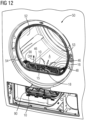
- FIG 12 illustrates a schematic partial perspective view of the laundry dryer 50 with the drying air filter 10 according to a preferred embodiment of the present invention.
- the laundry dryer 50 includes a laundry drum 52.
- An opening frame 54 is arranged in front of the laundry drum 52.
- the drying air filter 10 is inserted in a seat 90 in the lower part of the opening frame 54.
- the air stream from the laundry drum 52 may enter the drying air filter 10 through the perforated inlet plate 46 of the first outer part 16 and the slotted inlet grid 48 of the first inner part 20.
- the air stream leaves the laundry drum 52 through the filter mesh 32.
- the user can easily access the tool handle 38 of the cleaning tool 36 without removing the drying air filter 10 from the laundry dryer 50.
- the cleaning tool 36 is arranged preferably just beneath the top side of the drying air filter 10. Further, the air stream from the laundry drum 52 may enter the drying air filter 10 through the opening of the top side of the drying air filter 10, where the cleaning tool 36 is arranged, between the first inner part 20 and the second inner part 22.
- the drying air filter 10 is arranged in an air channel between the laundry drum 52 and a condenser.
- the drying air filter 10 is arranged in the air channel between the laundry drum 52 and a heat exchanger or the condenser.
- the drying air filter 10 is arranged in the air channel between the laundry drum 52 and an air exhaust.
- the inner parts 20 and 22 or the outer parts 16 and 18 with their respective frames 16a, 18a, 20a and 22a and the corresponding grids 16b, 18b, 20b and 22b, respectively, may be formed as single-piece parts in each case, for instance as injection moulded plastic parts.
- the filter does not need to comprise four main components 16 and 18 and 20 and 22 or two shells 12 and 14 at all. It may be sufficient, in an alternative embodiment, to have just two filter parts, for instance the parts 18 and 22, one having a mesh supporting grid carrying a filter mesh and the other having a propping grid, wherein the ribs of the two grids are contacted at various crossing points according to the invention, and one of the supporting grids supporting the filter mesh.
- the elements or components of the filter do not need to be pivotably connected with or hinged to each other, but may, for instance, also be connected as to be mounted and dismounted by an essentially linear mounting movement or in a stacking way.
- the outer shell 12 and the inner shell 14 may be formed as bags in each case, wherein the inner shell 14 is nested or nestable inside the outer shell 12. In this case, at least the inner hinge 25 is not necessarily required. If the inner shell 14 can be linearly inserted into the outer shell 12, then the outer hinge 24 is not necessarily required either.
- outer part and the inner part 16 and 20 or 18 and 22 of one or both shells 12 and 14 or the two filter parts in the alternative embodiment may be rigidly fixed to each other or even be made as an integral part for instance by two step moulding, thus reducing the possibility for pivoting or other movement with respect to each other.
- a collecting space for the fluff or lint may be formed not only between two filter parts, such as between the two inner parts 20 and 22 of the inner shell 14 and their filter meshes 32 and 33, but also between a filter part and the seat for the filter in the laundry dryer housing such as the opening frame or the base.
- further filter meshes may be provided at the propping grids 16b and 18b.
- the respective further filter mesh may be arranged upstream of the respective propping grid 16b or 18b.
- each of the further filter meshes are integrally arranged with the respective propping grids 16b or 18b, such that the respective filter mesh is at least partly extending through the respective propping grid 16b or 18b. That is, seen from the direction of the drying air A, the respective propping grid 16b and 18b is surrounding the respective further filter mesh on the upstream side and the downstream side of the further filter mesh.
- the arrangement of the respective further filter mesh in relation to the respective propping grid 16b or 18b is similar to the arrangement of the respective filter mesh 32 or 33 in relation to the respective mesh supporting grid 20b or 22b.
- the drying air filter may comprise two of the inner parts and two of the outer parts, just as the embodiment described in relation to FIGs 5 to 12 . That is, the drying air filter comprises an inner shell having two of the described inner parts facing each other, to form an intermediate space between the two inner parts, and an outer shell having two of the described outer parts facing each other each other, such that when the filter 10 is closed, the two inner parts are connected to each other in an airtight way with an opening to let drying air A into the intermediate space, such that the drying air A guided into the intermediate space between the two inner parts is divided into two air streams each flowing through the respective air passage area (and thus the respective filter mesh 6) of the respective inner part before reaching the respective outer part.
- fluff and other foreign material will be collected on the inside, upstream, of the respective filter mesh 6 of the respective inner part.
- the filter mesh for instance 6, 32 and 33, may in all embodiments, as shown, be arranged and supported on one side, preferably a top side or outer side, of the supporting rib(s) or supporting grid, and the propping rib(s) or propping grid be arranged on the opposite side, preferably a lower side or outer side, of the supporting rib(s) or supporting grid.
- the filter mesh may however, alternatively or additionally, in embodiments not explicitly shown, also be arranged or supported, at least partially, in a recessed manner or being offset or displaced from an outer surface or side of the supporting rib(s) or supporting grid, for instance be arranged inside the supporting grid opening(s) and in particular be supported at its respective edge by the supporting rib(s), in particular at a respective side section of the supporting rib(s) delimiting the respective supporting grid opening.
- drying air filter as shown in FIGs 1 and 2 or FIGs 3 and 4 , is illustrated to show an alternative way to arrange the supporting grid, the inner frame, the propping grid and the outer frame, compared to FIGs 5 to 12 .
- the drying air filter as shown in FIGs 1 and 2 or FIGs 3 and 4 , may comprise other features mentioned in relation to the description of FIGs 5 to 12 .
Landscapes
- Engineering & Computer Science (AREA)
- Textile Engineering (AREA)
- Detail Structures Of Washing Machines And Dryers (AREA)
- Filtering Of Dispersed Particles In Gases (AREA)
Abstract
a) at least one filter mesh (3, 6, 32, 33)
b) at least one supporting grid (2, 5, 20b, 22b) provided for supporting the filter mesh (3, 6, 32, 33) and comprising supporting ribs (8, 11, 34, 35) and supporting grid openings (27, 29), which are at least partially separated from each other by at least one or more of the supporting ribs (8, 11, 34, 35) and which define an air passage area for passing through of the drying air (A),
c) at least one propping grid (4, 7, 16b, 18b) provided for propping up the at least one supporting grid (20b, 22b), the at least one propping grid (4, 7, 16b, 18b) comprising propping ribs (9, 13, 26, 28) and propping grid openings (66, 68), which are at least partially separated from each other by at least one or more of the propping ribs (9, 13, 26, 28) and which are at least partially provided for passing through of the drying air (A),
d) wherein at least one contact portion (45, 47, X1, X3, X6, XA, XB, XC) is arranged to provide contact between at least one supporting rib (8, 11, 34, 35) and at least one propping rib (9, 13, 26, 28) in order to prop up the respective supporting rib (8, 11, 34, 35).
Description
- The present invention relates to a drying air filter for a laundry dryer. Further, the present invention relates to a laundry dryer comprising a drying air filter.
- In a laundry dryer (or: clothes dryer) usually a drying air filter is provided for collecting foreign particles, in particular fluff or lint occurring or generated when the laundry is treated by a hot air stream. The laundry is usually inside a rotating laundry drum and the air stream from the laundry drum passes through the drying air filter and the foreign particles are filtered out by the drying air filter and the air stream leaves the drying air filter substantially free from foreign particles and may enter another component of the dryer depending on the type of dryer, the component being for instance a heat exchanger in a condenser dryer or a heat pump in a heat pump dryer or also an exhaust in an open loop.
- The drying air filter usually comprises a filter mesh (or: filter net or filter fabric), which is held by a filter frame or support. The drying air filter may be arranged within a door or the frame surrounding the door or within a base below the drum and is mounted in an easily accessible and cleanable manner to remove the fluff or lint. The user can at least partially demount or detach the filter, in particular by pulling the filter out from its seat or unfolding it or removing it completely.
- After the user has fully or partially demounted the drying air filter from the laundry dryer, the lint or fluff may be removed or disposed of in a filter cleaning procedure by means of the user's fingers or an external tool for scratching the fluff or lint off the surface of the filter mesh. However, the filter mesh and even the filter frame may be damaged during the cleaning procedure by the external tool. Further, the drying air filter may be damaged during removing from and inserting into the laundry dryer.
-
WO 2018/121869 A1 discloses a filter assembly in a laundry dryer positioned at least partially in a duct defining a flow passage for process air exiting the drum, so as to filter process air flowing in the duct, and preferably below the drum at the rim of the aperture. The filter assembly includes a frame defining a storage portion and a filter mesh with a filtering surface supported by a matrix-like support structure with orthogonally crossing webs or ribs of the frame. In particular, the filter assembly includes a substantially wedge-shaped filtering cartridge or shell in a frame. The shell includes a first part with a filter mesh and a second part with a filter mesh, the first part and the second part of the shell being hinged to each other. A cleaning device for cleaning the filtering surface is provided including a translatable wiper with a handle to wipe the filtering surface during translating. The filtered material wiped off the filtering surface by the wiper is collected in the storage portion. -
WO 2018/121871 A1 discloses a filter assembly in a laundry dryer positioned at least partially in a duct defining a flow passage for process air exiting the drum, so as to filter process air flowing in the duct, and preferably below the drum at the rim of the aperture. The filter assembly includes a frame and a filter mesh with a filtering surface supported by a semi-circular grid-like support structure with radially and circumferentially crossing webs or ribs of the frame. A cleaning device for cleaning the filtering surface is provided including a wiper to wipe the filtering surface, said wiper being positioned in a wiper seat, and a manually operable handle connected to the wiper. The cleaning device is pivotably attached to the frame, so as to rotate around an axis to wipe the filtering surface. -
WO 2018/121872 A1 discloses a filter assembly in a laundry dryer positioned at least partially in a duct defining a flow passage for process air exiting the drum, so as to filter process air flowing in the duct, and preferably below the drum at the rim of the aperture. The filter assembly includes a frame and a filter mesh with a filtering surface supported by the frame. A cleaning device for cleaning the filtering surface is provided including a roto-translatable wiper having a handle to wipe the filtering surface during translating. The wiper is connected by means of a pin-guide connection to a portion of said frame to allowing a portion of the wiper to perform a rotational and translational movement with respect to said frame. - In these known solutions disclosed in
WO 2018/121869 A1 ,WO 2018/121871 A1 andWO 2018/121872 A1 the filter mesh can be cleaned in situ, i.e. while the filter is still mounted or without having to demount the filter, by gripping the handle of the wiper and moving the wiper to remove and scratch off the fluff and lint off the filter mesh. - It is an object of the present invention to provide a new drying air filter for a laundry dryer. The drying air filter shall in particular allow a reliable cleaning of the filter mesh using a cleaning tool, even without having to demount the drying air filter from the laundry dryer.
- The object of the present invention is achieved by embodiments according to the invention, in particular by a drying air filter according to
claim 1. - The drying air filter according to
claim 1 is provided for a laundry dryer and comprises - a) at least one filter mesh
- b) and at least one mesh supporting grid for supporting the filter mesh and comprising at least one supporting rib and supporting grid openings, which supporting grid openings are at least partially separated (or: divided) from each other by at least one or more of the at least one supporting rib and which define an air passage area for passing through of the drying air.
- The drying air filter further comprises
- c) at least one propping grid (or: backing grid) provided for propping up (or: backing) the at least one supporting grid, wherein the at least one propping grid comprises at least one propping rib and propping grid openings, which propping grid openings are at least partially separated from each other by at least one or more of the propping ribs and provided for allowing the drying air to pass through,
- d) wherein at least one contact portion is arranged to provide contact between at least one supporting rib and at least one propping rib in order to prop up the respective supporting rib.
- The propping grid stabilizes the supporting grid against deformation by a cleaning tool or a hand cleaning the filter mesh and, nevertheless, a decrease in drying air flow through the filter is kept low.
- Further embodiments and improvements according to the invention are set forth in the dependent claims.
- The embodiments disclosed herein are only examples, and the scope of this disclosure is not limited to them. Particular embodiments may include all, some, or none of the components, elements, features, functions, operations, or steps of the embodiments disclosed herein. Embodiments according to the invention are in particular disclosed in the attached claims, wherein any feature mentioned in one claim category can be claimed in another claim category as well. The dependencies or references back in the attached claims are chosen for formal reasons only. However, any subject matter resulting from a deliberate reference back to any previous claims (in particular multiple dependencies) can be claimed as well, so that any combination of claims and the features thereof are disclosed and can be claimed regardless of the dependencies chosen in the attached claims. The subject-matter which can be claimed comprises not only the combinations of features as set out in the attached claims but also any other combination of features in the claims, wherein each feature mentioned in the claims can be combined with any other feature or combination of other features in the claims. Furthermore, any of the embodiments and features described or depicted herein can be claimed in a separate claim and/or in any combination with any embodiment or feature described or depicted herein or with any of the features of the attached claims.
- In a preferred embodiment, at least one contact portion comprises at least one protrusion at the respective supporting rib and/or the respective propping rib. A corresponding protrusion or recess at the corresponding other rib or a hook like connection may be provided, in particular in an embodiment where in at least one contact portion a shape-locking contact is provided.
- In a preferred and advantageous embodiment, at least one or several of the propping ribs of the at least one propping grid crosses or cross at least one or several of the at least one supporting rib of the at least one supporting grid at at least one respective crossing point, seen from the direction of the drying air, and at least one or each contact portion is arranged at a corresponding crossing points.
- Preferably, at least at a crossing point where a contact portion is arranged, an angle between the crossing propping rib and supporting rib is selected from an interval between 60° and 120°, in particular 80° to 100°, preferably 90°. By choosing these relatively large angles also transversal force components exerted onto the supporting grid may be absorbed by the propping grid. The angles between crossing propping ribs and supporting ribs may also differ at at least two of the crossing points with contact portions to allow for a more uniform (or: homogenous) force distribution and transmission.
- In an embodiment the drying air filter further comprises
- an outer shell having a first outer part and a second outer part,
- an inner shell having a first inner part and a second inner part,
- wherein each of the inner parts of the inner shell comprises one of the at least one supporting grid supporting at least one of the at least one filter meshes,
- wherein each of the outer parts of the outer shell comprises one of the at least one propping grids for propping up the respective supporting grid of the respective inner part. Thereby an intermediate space is formed within the inner shell between the first inner part and the second inner part.
- Preferably, the first inner part has a first inner frame forming a first inner air passage and the second inner part has a second inner frame forming a second inner air passage, the inner shell being arranged such that, in a closed or mounted state of the drying air filter, the first inner frame and the second inner frame engage with each other to form the inner shell, the first supporting grid being connected to or being a part of the first inner frame, extending across the first inner air passage, the second supporting grid being connected to or being a part of the second inner frame, extending across the second inner air passage. The first inner air passage may correspond to the air passage area for a first stream of drying air. Further, the second inner air passage may correspond to the air passage area for a second stream of drying air.
- The two supporting grids of the two inner parts may be configured to be mirror-symmetrical to each other and/or congruent and/or the two propping grids of the two outer parts may be configured to be mirror-symmetrical to each other and/or congruent.
- Regarding the shape of the supporting ribs and/or the propping ribs at least some or most or all them may be linear or straight, although some of the ribs may also be curved, and/or at least some or all of the supporting ribs and/or the propping ribs have a circular or a polygonal or an elongated streamlined cross-section.
- In a preferred embodiment of the drying air filter, the or each supporting grid and/or the or each propping grid is composed of several grid cells formed by the grid openings and the adjacent or partially surrounding grid ribs and optionally also border ribs or rims. Preferably, at least two of the grid cells of one or each of the grids differ from each other in size and/or shape, thus forming in particular an irregular grid. In an advantageous embodiment, at least a majority of the grid cells of the supporting grid and/or of the propping grid are of polygonal shape, preferably at least two or three different polygonal shapes, including in particular trigonal shapes, quadrilateral shapes and pentagonal shapes. In order to achieve a good force distribution, the grid cell pattern of the supporting grid differs, in a preferred embodiment, from the grid cell pattern of the propping grid in at least one of the number, the shape and the size of the grid cells.
- In order to improve the connection between the propping ribs and the supporting ribs at the contact portions one or more of the following measures may be taken:
- (i) providing material of high friction for the supporting ribs and propping ribs at least at the crossing points,
- (ii) providing a shape-locking connection, e.g. protrusion and recess, between the supporting ribs and propping ribs at least at one or more contact portions,
- (iii) providing a fastening, in particular snapping connection, between the supporting ribs and propping ribs at least at one contact portion.
- In a preferred embodiment the drying air filter further comprising a cleaning tool for cleaning, in particular wiping or scraping, the or each filter mesh in a cleaning movement across the mesh surface, in particular to remove lint or fluff from the mesh. The cleaning movement may be a rotatory or pivoting movement about a rotational axis or a translational or a combination of rotatory and translational movement. The cleaning tool may comprise a handle for manually moving the cleaning tool. In an embodiment with two shells or two meshes the cleaning tool is in particular arranged, at least partly, in an intermediate space between the first inner part and the second inner part and/or between the two filter meshes for simultaneously cleaning both filter meshes.
- In a preferred embodiment the at least one contact portion is arranged within an inner area of the air passage area defined by the support grid openings of at least one supporting grid, wherein the inner area within one third and two thirds of the air passage area. The inner area preferably extends within one fourth and three fourths, preferably between one third and two thirds, of at least one diameter of the air passage area. In an alternative, the majority of the at least one contact portion is arranged within the inner area. In a further alternative, the at least one contact portion is arranged within the inner area.
- In all embodiments the at least one filter mesh and the corresponding at least one supporting grid supporting the at least one filter mesh may form separate parts, in particular may be independently produced, or also may form an integral part or single-piece, in particular may be formed integrally in one production process.
- In another preferred embodiment the at least one filter mesh is arranged on a first side, preferably a first outer side, of the at least one supporting rib of the supporting grid and the at least one propping rib props up the respective at least one supporting rib at a second side, preferably a second outer side, opposite to the first side, of the at least one supporting rib.
- Preferably, the filter mesh is supported, at least partially, on an outer side of the supporting grid or supporting rib(s).
- Alternatively or additionally, in a further embodiment, the at least one filter mesh is, at least partially, offset (or: displaced, recessed) from an outer side of the supporting grid, and/or arranged inside the supporting grid opening(s) and preferably supported at its respective edge by the supporting rib(s), in particular by a respective side section of the supporting rib(s) delimiting the respective supporting grid opening.
- In an advantageous embodiment the at least one propping grid or propping rib is arranged downstream of the at least one supporting grid, seen from the direction of the drying air.
- Also the at least one propping grid may preferably be arranged on an outer side of the at least one supporting grid.
- The invention in a further embodiment also relates to a laundry dryer comprising at least one drying air filter according to an embodiment of the invention for filtering the drying air used or having been used for drying laundry. The drying air filter is preferably detachably arranged in a seat of an opening frame of the dryer.
- The invention will be described further in the following, also with reference to the drawings.
- FIG 1
- illustrates, in a schematic perspective view, an embodiment of a drying air filter for a laundry dryer with one mesh supporting grid and one propping grid during mounting,
- FIG 2
- illustrates, in a schematic perspective view, the embodiment of
FIG 1 with the two grids in a mounted state with two contact portions, - FIG 3
- illustrates, in a schematic perspective view, another embodiment of a drying air filter for a laundry dryer with one mesh supporting grid and one propping grid during mounting and
- FIG 4
- illustrates, in a schematic perspective view, the embodiment of
FIG 3 with the two grids in a mounted state with just one contact portion, - FIG 5
- illustrates a perspective view of a drying air filter for a laundry dryer with two pivotably connected shells according to a preferred embodiment of the present invention,
- FIG 6
- illustrates a further schematic perspective view of the drying air filter according to
FIG 5 with the two shells disconnected, - FIG 7
- illustrates another schematic perspective view of the drying air filter according to
FIGs 5 and6 with the two inner parts of the inner shell being closed and attached one outer part of the outer shell according to the preferred embodiment of the present invention, - FIG 8
- illustrates a schematic perspective view of a cleaning tool for the drying air filter according to a preferred embodiment of the present invention, in particular according to
FIGs 5 to 7 , - FIG 9
- illustrates a schematic perspective front view of an outer shell of the drying air filter according to a preferred embodiment of the present invention, in particular according to
FIGs 5 to 7 , - FIG 10
- illustrates a schematic perspective front view of an inner shell of the drying air filter according to the preferred embodiment of the present invention, in particular according to
FIGs 5 to 7 , - FIG 11
- illustrates a further schematic front view of the second inner part upon the second outer part of the drying air filter according to the preferred embodiment of the present invention, in particular according to
FIGs 5 to 7 , - FIG 12
- illustrates a schematic partial perspective view of a laundry dryer with the drying air filter according to a preferred embodiment of the present invention, in particular according to any of
FIGs 5 to 7 and10 and 11 . - In an example,
FIG 1 illustrates, in a schematic perspective view, an embodiment with one mesh supporting grid and one propping grid during mounting andFIG 2 illustrates, in a schematic perspective view, the embodiment ofFIG 1 with the two grids in a mounted state with two contact portions. The drying air filter comprises: - a) a
filter mesh 3, - b) a supporting
grid 2 provided for supporting thefilter mesh 3 and comprising two supportingribs 8 and supporting grid openings, which are at least partially separated from each other by the supportingribs 8 and which define an air passage area for passing through of the drying air A, - c) a propping grid 4 provided for propping up the supporting
grid 2, the propping grid 4 being arranged downstream of the supportinggrid 2, seen from the direction of the drying air A, the propping grid 4 comprising two proppingribs 9 and propping grid openings, which are at least partially separated from each other by the proppingribs 9 and which are at least partially provided for passing through of the drying air A, - d) wherein two contact portions XA, XB are arranged to provide contact between each of the supporting
ribs 8 and one of the proppingribs 9 in order to prop up the respective supportingrib 8. Each of the two contact portions XA, XB may be arranged at a crossing point, seen from the direction of the drying air A, between the respective supportingrib 8 and the respective proppingrib 9. - In both of the above-described examples, fluff and other foreign material will be collected on the upstream side of the
filter mesh 3 or 6. Thus, during cleaning of the filter, the user may access the filter, with for example a fingers or a cleaning tool, from the upstream side of thefilter mesh 3 or 6 and apply a force on thefilter mesh 3 or 6 and the supportinggrid grid 4 or 7 is propping up the supportinggrid filter mesh 3 or 6, from the downstream side of thefilter mesh 3, such that the supportinggrid filter mesh 3 or 6 are less deformed during cleaning of the filter. - In the embodiment for a drying air filter as shown in
FIGs 1 and 2 a supportinggrid 2 with amesh 3 having asemi-circular border rib 17 and two interior linear supportingribs 8 forming a V inside theborder rib 17 is placed onto a propping grid 4 having asemi-circular border rib 19 and a concentric proppingrib 9 and a linear central proppingrib 9. Further, supporting grid openings are formed within the supportinggrid 2, separated from each other by the supportingribs 8 and which define an air passage area for passing through of the drying air A. Yet further, propping grid openings are formed within the propping grid 4, separated from each other by the proppingribs 9. The propping grid openings are at least partially provided for passing through of the drying air A. As shown inFIG 10 , two crossing points XA and XB are formed between the supportingribs 8 and the propping ribs 9 (in this case the semi-circular propping rib 9), wherein at each of the two crossing points XA and XB is a contact portion XA and XB provided for propping up thesupport grid 2 by the propping grid 4. Hence, the contact portions XA and XB are arranged at the respective crossing points between the supportingribs 8 and the proppingribs 9. At the respective contact portion, the angle between thecrossing propping rib 9 and the supportingrib 8 could be about 60° to 90°, preferably about 90°. In this case, theinner frame 17, forming the air passage area, is semi-circular and thus the inner area can be defined based on a radius from the point where the two supportingribs 8 coincide to the circular part of theinner frame 17. Thus, the contact portions XA and XB are arranged within an inner area of the semi-circular air passage extending between one fourth and three fourths of the radius of the semi-circular air passage. Preferably, the contact portions XA and XB are arranged within an inner area of the semi-circular air passage extending between one third and two thirds of the radius of the semi-circular air passage. - This circular embodiment is also suitable for a rotating cleaning tool (further explained below). The direction of the drying air is indicated by the arrow A in
FIG 2 . Thus, the propping grid 4 is arranged downstream of the supportinggrid 2, seen from the direction of the drying air A. In one example an inner part of the filter comprises the supportinggrid 2. Further, theborder rib 17 may be aninner frame 17, such that the supportinggrid 2 is connected to or is a part of theinner frame 21. Further, an outer part of the filter may comprise the propping grid 4. Further, theborder rib 19 may be anouter frame 19, such that the propping grid 4 is connected to or is a part of theinner frame 21. - An alternative way to describe the drying air filter of
FIG 1 and FIG 2 is that the drying air filter comprises an inner part and an outer part. The inner part may comprise: - an
inner frame 17 forming the air passage area; - supporting
ribs 8 being connected to theinner frame 17 and extending across the air passage area; and - a
filter mesh 3 being attached to theinner frame 17 and the supportingribs 8 and extending across the air passage area. - The supporting
grid 2 may in this case correspond to the supportingribs 8. Alternatively, the supportinggrid 2 may correspond to the supportingribs 8 and theinner frame 17. - The outer part may comprise:
- an
outer frame 19; and - a propping
ribs 9 being connected to theouter frame 19 and extending across the air passage area. - Each of the propping
ribs 9 is crossing one of the supportingribs 8 at a respective crossing point XA and XB. The propping grid 4 may in this case correspond to the proppingribs 9. Alternatively, the propping grid 4 may correspond to the proppingribs 9 and theouter frame 19. - In another example,
FIG 3 illustrates, in a schematic perspective view, an embodiment with one mesh supporting grid and one propping grid during mounting andFIG 4 illustrates, in a schematic perspective view, the embodiment ofFIG 3 with the two grids in a mounted state with two contact portions. The drying air filter comprises: - a) a filter mesh 6,
- b) a supporting
grid 5 provided for supporting the filter mesh 6 and comprising a supportingrib 11 and supporting grid openings, which are at least partially separated from each other by the supportingrib 11 and which define an air passage area for passing through of the drying air A, - c) a propping
grid 7 provided for propping up the supportinggrid 5, the proppinggrid 7 being arranged downstream of the supportinggrid 5, seen from the direction of the drying air A, the proppinggrid 7 comprising a proppingrib 13 and propping grid openings, which are at least partially separated from each other by the proppingrib 13 and which are at least partially provided for passing through of the drying air A, - d) wherein a contact portion XC is arranged to provide contact between the supporting
rib 11 and the proppingrib 13 in order to prop up the respective supportingrib 11. The contact portion XC may be arranged at a crossing point, seen from the direction of the drying air A, between the supportingrib 11 and the respective proppingrib 13. - In the further embodiment for a drying air filter as shown in
FIGs 3 and 4 a supportinggrid 5 with a mesh 6 having arectangular border rib 21 and a linear central supportingrib 11, is placed onto a proppinggrid 7 having arectangular border rib 23 and a linear central proppingrib 13. Further, supporting grid openings are formed within the supportinggrid 5, separated from each other by the supportingrib 11 and which define an air passage area for passing through of the drying air A. Yet further, propping grid openings are formed within the proppinggrid 7, separated from each other by the proppingrib 13. The propping grid openings are at least partially provided for passing through of the drying air A. As shown inFIG 4 , a crossing point XC, which in this case is also a contact portion XC, is formed between the supportingrib 11 and the proppingrib 13, for propping up thesupport grid 2 by the propping grid 4. The angle between the crossingribs FIG 4 . Thus, the proppinggrid 7 is arranged downstream of the supportinggrid 5, seen from the direction of the drying air A. In one example an inner part of the filter comprises the supportinggrid 5. Further, theborder rib 21 may be aninner frame 21, such that the supportinggrid 5 is connected to or is a part of theinner frame 21. Further, an outer part of the filter may comprise the proppinggrid 7. Further, theborder rib 23 may be anouter frame 23, such that the proppinggrid 7 is connected to or is a part of theinner frame 21. - An alternative way to describe the drying air filter of
FIG 3 and FIG 4 is that the drying air filter comprises an inner part and an outer part. The inner part may comprise: - an
inner frame 21 forming the air passage area; - a supporting
rib 11 being connected to theinner frame 21 and extending across the air passage area; and - a filter mesh 6 being attached to the
inner frame 21 and the supportingrib 11 and extending across the air passage area. - The supporting
grid 5 may in this case correspond to the supportingrib 11. Alternatively, the supportinggrid 5 may correspond to the supportingrib 11 and theinner frame 21. - The outer part may comprise:
- an
outer frame 23; and - a propping
rib 13 being connected to theouter frame 23 and extending across the air passage area. - The propping
grid 7 may in this case correspond to the proppingrib 13. Alternatively, the proppinggrid 7 may correspond to the proppingrib 13 and theouter frame 23. A contact portion XC is arranged at the crossing point between the supportingrib 11 and the proppingrib 13. In this case the contact portion XC is arranged in the middle of the air passage area. - Although
FIGs 3 and 4 only show one inner part and one outer part, it should be understood that the drying air filter may comprise two of the inner parts and two of the outer parts, just as the embodiment described in relation toFIGs 5 to 12 . That is, the drying air filter comprises an inner shell having two of the described inner parts facing each other, to form an intermediate space between the two inner parts, and an outer shell having two of the described outer parts facing each other each other, such that when thefilter 10 is closed, the two inner parts are connected to each other in an airtight way with an opening to let drying air A into the intermediate space, such that the drying air A guided into the intermediate space between the two inner parts is divided into two air streams each flowing through the respective air passage area (and thus the respective filter mesh 6) of the respective inner part before reaching the respective outer part. Thus, fluff and other foreign material will be collected on the inside, upstream, of the respective filter mesh 6 of the respective inner part. -
FIG 5 to 7 each illustrate a schematic perspective view of a dryingair filter 10 for a laundry dryer 50 (shown inFIG 12 ) according to a preferred embodiment of the present invention. InFIG 5 the dryingair filter 10 is in an opened or demounted state. - The drying
air filter 10 comprises anouter shell 12 and aninner shell 14. Theouter shell 12 includes a firstouter part 16 and a secondouter part 18 which are hinged to each other by means of ahinge 24 and can be moved about thathinge 24 in a pivoting movement P3. Theinner shell 14 includes a firstinner part 20 comprising aninner frame 20a and amesh supporting grid 20b having supportingribs 34 supporting afilter mesh 32, and further includes a secondinner part 22 comprising aninner frame 22a and amesh supporting grid 22b having supportingribs 35 supporting anotherfilter mesh 33. Thereby an intermediate space is formed within the inner shell between the first inner part and the second inner part. The firstinner part 20 and the secondinner part 22 of theinner shell 14 may be hinged to each other by means of ahinge 25 and can be moved about thathinge 25 in a pivoting movement P2. Other means to connect the firstinner part 20 and the secondinner part 22 are possible too. - The
inner shell 14 and theouter shell 12 are removably and pivotably connected with each other by means of a rotatable, preferably snapping or clipping, connection of thehinge 25 of theinner shell 14 at the two ends into two respective, in particular sleeve-like or hollow pin like, hingebearings 41 at theouter shell 12, in particular at the secondouter part 18. Other means to connect theinner shell 14 and theouter shell 12 are possible too. - Since the
outer shell 12 and theinner shell 14 can be opened separately by their respective pivoting movements P2 and P3 and they can be pivoted with respect to each other by a pivoting movement P1, a high degree of freedom of motion for cleaning of the filter meshes 32 and 33 and the intermediate space between the two filter meshes 32 and 33 from fluff or lint is achieved. - The first
outer frame 16a of the firstouter part 16 as well as the secondouter frame 18a of the secondouter part 18 each surrounds the corresponding first proppinggrid 16b or second proppinggrid 18b, forming arim grid - The first
inner frame 20a of the firstinner part 20 as well as the secondinner frame 22a of the secondinner part 22 each define the boundary of an air passage for the drying air and each surround the corresponding firstmesh supporting grid 20b or secondmesh supporting grid 22b, so that eachmesh supporting grid corresponding mesh grid respective filter mesh - In a closed state of the drying
air filter 10, in particular when mounted into itsseat 90 in the laundry dryer 50 (seeFIG 12 ), the firstouter part 16 and the firstinner part 20 are arranged substantially parallel to each other and the secondinner part 22 and the secondouter part 18 are arranged substantially parallel to each other and the twoinner parts inner shell 14 may be (slightly) inclined to each other or also be arranged parallel to each other. The different parts, typically the twoouter parts filter 10 are preferably connected with each other in the closed state, for instance by snapping or clipping means. A filter handle 15 is provided for handling thefilter 10, in particular pulling thefilter 10 out of itsseat 90 if needed. - In the closed state of the
filter 10 and when thefilter 10 is mounted into itsseat 90 in thelaundry dryer 50, drying air A of thelaundry dryer 50, typically moistured drying air A coming from the drum 52 (seeFIG 12 ), passes into or is guided into the intermediate space between the filter meshes 32 and 33. In the embodiment shown the firstouter part 16 comprises aperforated inlet plate 46 at itsframe 16a and the firstinner part 20 comprises a slottedinlet grid 48 at itsframe 20a for forming, in the closed state of thefilter 10, an inlet passage for the drying air A into thefilter 10 and the intermediate space between the two filter meshes 32 and 33. - The drying air A then passes or flows from this intermediate space through the two flow paths or passages each constituted by the
corresponding filter mesh grid grid inner shell 14 through theinner shell 14 and theouter shell 12 outwardly to the outside of theouter shell 12. The filtered drying air exiting thefilter 10 is then guided to a different space inside thelaundry dryer 50 for further processing such as either removal of moisture by means of a heat exchanger or heat pump and heating up the air again and returning it as fresh drying air into the drum, or simply for direct discharge into the environment. This flow of the drying air A is indicated inFIG 5 by respective arrows. Thus, the first proppinggrid 16b is arranged downstream of the first supportinggrid 20b, seen from the direction of the drying air A. Further, the second proppinggrid 18b is arranged downstream of the second supportinggrid 22b, seen from the direction of the drying air A. - There are several possible implementations of arranging the
respective filter mesh ribs grid filter mesh 32 may be arranged upstream of the supportingribs 34 and/or the first supportinggrid 20b, seen from the direction of the drying air A, resting against, or being fixed to, the supportingribs 34 and/or themesh supporting grid 20b. Further, also thefilter mesh 33 may be arranged upstream of the supportingribs 35 and/or themesh supporting grid 22b, resting against, or being fixed to, the supportingribs 35 and/or themesh supporting grid 22b. - In another example, the
filter mesh 32 is at least partly integrally arranged with the supportingribs 34 and/or themesh supporting grid 20b, such thatfilter mesh 32 is at least partly extending through the supportingribs 34 and/or themesh supporting grid 20b. That is, seen from the direction of the drying air A, the supportingribs 34 and/or themesh supporting grid 20b, may be arranged on the upstream side and the downstream side of thefilter mesh 32 and firmly holding the filter mesh. In a further example, also thefilter mesh 33 is integrally arranged with the supportingribs 35 and/or the secondmesh supporting grid 22b. During production, the at least one supportinggrid filter mesh ribs grid ribs grid filter mesh ribs grid filter mesh - During the passage through the drying
air filter 10, the drying air A is filtered from fluff or lint or other undesired particles, which may be created during drying of the laundry or be general dirt or dust, by the filter meshes 32 and 33. The filtered fluff or lint or filtration residue stays partially in the intermediate space between the filter meshes 32 and 33 or may fall or be sucked into a collecting space inside thefilter 10 and/or in theseat 90. - A significant part of the filtered particles or residue such as fluff or flint stays, however, on the inner surfaces of the filter meshes 32 and 33 and sticks thereto. Therefore, a mechanical cleaning, such as scraping or wiping off, of the filter meshes 32 and 33, for removal of the filtered polluting material such as fluff or lint, sticking to the surfaces of the filter meshes 32 and 33, is needed or at least beneficial at regular intervals after operation of the dryer to not obstruct the flow of air by the polluted filter meshes 32 and 33.
- This cleaning action or removal of the fluff or lint sticking to the surfaces of the filter meshes 32 and 33, which are opposing each other, may, in one embodiment of the invention, be achieved in a conventional way by dismounting or detaching the
filter 10 from itsseat 90 in thelaundry dryer 50 and opening theouter shell 12 and then theinner shell 14 of thefilter 10 as to make the filter meshes 32 and 33 accessible and using the fingers or a tool for scratching the dirt layer or sticking fluff or lint off the filter meshes 32 and 33. - In the preferred embodiment according to the invention shown in the drawings, a cleaning tool (or scratching tool, wiper, scraper) 36 is associated with or contained by the drying
filter 10, preferably arranged, in particular removably arranged, within the inner shell 14 (in the closed state of the filter 10). Thecleaning tool 36 is shown attached to theinner part 22 of theinner shell 14 in a resting state inFIGs 5 and6 and in a detached state in more detail inFIG 8 . Thecleaning tool 36 can be moved across at least one, preferably both, of the filter meshes 32 and 33 in a cleaning movement parallel to the mesh surface. For removing or scratching off or wiping off the fluff, lint of other filter residue from the surface of thefilter mesh cleaning tool 36 has two cleaning (or: scratching, wiping)contours 37 at opposite sides. - Each cleaning
contour 37, in the closed state of the dryingair filter 10, swipes or glides across the surface of thecorresponding filter mesh cleaning tool 36 with itscleaning contours 37 cleans the surfaces of both filter meshes 32 and 33 simultaneously, thereby removing fluff and lint, in general foreign particles, from the filter meshes 32 and 33 at the same time. - In the embodiment shown the cleaning movement is a rotating (or: pivoting) movement about an axis of rotation defined by an
axle 42 arranged at theinner part 22 orinner shell 14, wherein thecleaning tool 36 is formed as a two-arm lever rotatably attached to theaxle 42 by means of anaxle bearing 39. The lever part with thecleaning contours 37 is arranged on one side of the axle bearing 39, and on the other side thecleaning tool 36 comprises atool handle 38 for gripping and actuating thecleaning tool 36 in the cleaning movement is arranged. Theaxle 42 is, in the closed state of theinner shell 14, received and stabilized by anaxle counterpart 44 at the otherinner part 20 of theinner shell 14. - The area to be cleaned by the
cleaning tool 36 is, therefore, a circular sector with theaxle 42 defining the centre and the radial length of the cleaningcontour 37 basically defining the radius of the circular sector. This circular sector preferably corresponds to the air passage for the drying air. The circular sector area to be cleaned is, thus, also defined and matched by the supportinggrids border rib inner frame axle 42 as the centre in the closed state and having a radius adapted to the radial length of thecleaning tool 36 or itscleaning contour 37 and the supportingribs FIG 11 ). In other words, the respective air passage area is the area thecleaning tool 36 is configured to clean. - When the
filter 10 is closed, theborder rib 30 of the firstinner part 20 and theborder rib 31 of the secondinner part 22 are connected to each other in an airtight way, such that the drying air A coming from thedrum 52, guided into the intermediate space between the filter meshes 32 and 33, only can exit thefilter 10 through the respective air passage area of the respective filter meshes 32 and 33, as explained above. When thefilter 10 is closed, a rigid connection is obtained between the firstinner part 20 and the secondinner part 22, along theborder ribs axle 42 and the counterpart of theaxle 44. Theborder ribs cleaning tool 36 to assist the cleaning movement of thecleaning tool 36. As can be seen inFIGs 5 to 7 and10 , the circular sector area surrounded or delimited by theborder rib inner frame inner rim inner frame FIG 3 and FIG 4 . -
FIG 10 depicts an embodiment of the supportinggrids inner shell 14 in more detail. The two supportinggrids inner parts hinge 25 in the closed state, but may also be not symmetrical to each other. - Each supporting
grid border rib ribs filter mesh - The circular sector supporting area of each supporting
grid ribs grid opening ribs border rib inner rim frame ribs border ribs - In a strip section between the
inner rim rib inner rim border rib - Between the
border rib rib inner rim border rib ribs - The area corresponding to the sum of the individual areas of the cells C1 to C7 without the surface areas of the supporting
ribs grid openings grid mesh grid openings - Such an irregular grid structure for the supporting
grid ribs axle 42 of the cleaning tool better compensates the forces exerted by the cleaning tool and transferred through theaxle 42 orcounterpart 44 into the supporting grid. The cells C1 to C7 in the embodiment ofFIG 10 are arranged in a mirror symmetrical way with respect to a central axis. It is also possible to have a non-symmetrical cell structure or grid for the supporting grids (not shown). - In embodiments not shown, the cleaning movement of the cleaning tool may also be translational or a combination of translation(s) and rotation(s), for instance as disclosed in the prior art mentioned above
WO 2018/121869 A1 orWO 2018/121872 A1 . The areas of the filter meshes and the supporting grids as well as the propping grids and their respective grid cells defining the air passages are then modified accordingly. The cleaning tool does not have to be arranged symmetrically with regard to the supporting grid or area of the filter mesh to be cleaned (as shown inFIG 10 for instance), but can also be arranged asymmetrically. Also, instead of or in addition to manually operating the cleaning tool it is also possible to use an automated actuation for the cleaning movement, for instance by means of an electric motor. - During the removal of the filter residue and fluff and lint from the surface of the filter meshes 32 and 33 an external cleaning tool, but in particular the
cleaning tool 36 with itsclearing contour 37 exerts cleaning forces onto both filter meshes 32 and 33 and the supportinggrids filter mesh grid filter mesh grid filter mesh grid cleaning tool 36 shall be avoided, so as to allow for efficient cleaning of the filter. - This could be achieved by providing rigid supporting ribs of a large cross-section and of low deformability. However, the rigid support of the filter meshes 32 and 33 by the corresponding supporting
grids air filter 10 significantly. - Now, according to embodiments of the invention, a rigid support of the supporting
grids inner shell 14 such as shown inFIG 10 , is provided by propping up (or: carrying, back supporting) each supportinggrid grid outer parts filter mesh grids FIGs 5 ,6 ,7 ,9 and11 . -
FIG 9 depicts an embodiment of the proppinggrids outer shell 12 in more detail. The two proppinggrids outer parts hinge 24 in the closed state, but may also be not symmetrical to each other. - The respective
outer frame inner rim grid grid ribs inner rim grids grid opening ribs inner rim outer frame grids ribs inner rims grid openings - Two long linear main propping
ribs grid 16b divide the grid in four sections and two further linear and inclined proppingribs rib inner rim rib - On the other side of the longer main propping
rib inner rim rib - In the embodiments shown, both grids, the supporting and the propping grids, are constructed as irregular grid or cell pattern composed of at least approximately polygonal shapes, which provides a good stability of the grids. However, the geometric grid structures or cell patterns of the propping
grids 16B and 18b on one hand and the supportinggrids - When the propping
grids FIG 9 and the supportinggrids FIG 10 are brought into the mounted state with respect to each other by closing theinner shell 14 and theouter shell 12 or thefilter parts FIG 11 just for theinner part 22 and theouter part 16, which however results in the same way also for theinner part 20 and theouter part 16, although not shown explicitly. - The supporting
grid 22b (or 20b) and its corresponding proppinggrid 18b (or 16b), due to the different grid structures or cell patterns, overlap at crossing points (or: crossing areas), seen from the direction of the drying air A, in the embodiment shown in particular crossing points X1 to X7, of the supporting ribs 35 (or 34) and their respective propping ribs 28 (or 26). - At least one of the crossing points X1 to X7 comprises an engaging portion or a contact portion arranged between the respective supporting
rib rib rib - Preferably, at least two of the crossing points X1 to X7 comprise contact portions arranged between the respective supporting
rib rib mesh supporting grid 22b (or 20b). - More preferably, at least three of the crossing points X1 to X7 comprise engaging or contact portions arranged between the respective supporting
rib rib mesh supporting grid 22b (or 20b). - In general, one, two, three or even more contact portions or area or engaging portion are provided between the propping grid and the respective supporting grid for propping up the supporting grid, preferably at crossing points or areas between respective ribs of the two grids.
- Each engaging or contact portion is preferably formed by a protrusion of at least one of the two grids, preferably at least one of the two ribs crossing at the respective crossing point, which protrusion, in the mounted state of the supporting grid and the propping grid, gets into contact with the other grid or rib.
- In the exemplary embodiments shown, in particular in
FIGs 10 and11 , engaging or contact portions are provided preferably at the crossing points X1, X3 and X6 by means ofprotrusions 45 at the supportingribs 34 of the supportinggrid 20b which come into contact with propping ribs of the proppinggrid 16b andprotrusions 47 at the supportingribs 35 of the supportinggrid 22b which come into contact with propping ribs of the proppinggrid 16b. - In the example shown in
FIG 10 theprotrusions ribs ribs FIG 11 . - Thus, generalizing, the contact portions are preferably arranged within an inner area of the air passage area defined by all the supporting
grid openings FIG 10 but can of course be shaped and arranged differently depending on the air passage area and the cleaning tool. - Preferably the inner area or the air passage area where most of or all contact portions are located is positioned between 1/4 and 3/4, preferably between 1/3 and 2/3, of at least one diameter of the air passage or cleaning area.
- In an example, at least one engaging or contact portion is positioned between a third and two thirds of the radius of the air passage area or of the length between the
border rib axle 42. In particular, within this range, the need for support is higher than closer to theinner frames border rib axle 42 where support is already obtained by the connection between the firstinner part 20 and the secondinner part 22 of theinner shell 14 when thefilter 10 is closed. - However, the number and locations of the engaging or contact portions may be chosen differently, also higher than three and/or at different positions and different crossing points alternatively or in addition. Also the contact portions do not need to be formed by separate protrusions. It is also even possible to introduce separate contact portions to be mounted as separate pieces between the ribs.
- In particular, several propping ribs 28 (or 26) of the propping
grid 18b (or 16b) each cross at least one respective supporting rib 35 (or 34) of the supportinggrid 22b (20b) at a respective crossing point X1 to X7 and wherein, at least one of the crossing points X1 to X7 comprises an engaging portion arranged between the respective supportingrib rib rib - At the crossing points X1 to X7, at least the crossing points X1, X3 and X6 with the contact portions, the supporting ribs and the propping ribs include rather large angles selected from a range of 45° to 90°, preferably different (interior) angles. For instance, at the crossing point X1 the (interior) angle α may be 90°, at the crossing point X3 the (interior) angle β may be around 65° to 85° and at the crossing point X6 the (interior) angle γ may be around 95° to 110°.
- By these rather steep crossing directions or (interior) angles preferably close to 90° between the supporting ribs and their propping ribs at the engaging or contact portions of the crossing points X1, X3 and X6 a considerable amount of (cleaning) force components are compensated transversally to the supporting ribs. Therefore, the supporting grid is propped up by the propping grid in force directions or regarding cleaning force components not only longitudinally or along the supporting ribs, but also transversally or perpendicular to the longitudinal direction of the supporting ribs.
- Due to the varying different interior angles, for example α, β or γ, which is a consequence of the different irregular grid structures or cell patterns of the two overlapping grids, the supporting grid and the propping grid, the (cleaning) forces are also distributed in a rather even or uniform way over the whole grid surface.
- The cross-sections of the supporting ribs or the propping ribs may be circular or polygonal or at least partially be streamlined for a low air flow resistance, for instance be elongated with the longer dimension extending along the air flow or perpendicular to a grid plane. The contact area between the ribs at the respective engaging portion may be punctiform for instance, if the cross-sections of both contacting ribs are both circular or of curved convex shape. The contact areas may also be contact lines, in particular linear contact lines, if the cross-section of one of the contacting ribs is circular or of curved convex shape and the cross-section of the other contacting rib has a flat edge and thus the rib a flat surface facing the other contacting rib.
- At least one engaging or contact point may be a two-dimensional contact area, if the cross-sections of the two contacting ribs are adapted or complementary in shape or the opposing contacting surfaces contact each other in a complementary manner. For example, at the at least one engaging or contact point, either the propping
rib rib - The force compensation effect may, thus, be increased by providing a shape-locking connection at at least one contact portion between the supporting rib and the corresponding propping rib, for instance by providing a protrusion at one of the ribs and a recess at the other rib receiving the protrusion at the crossing point (or the protrusion engaging in the recess) as a special form of (partially) complementary opposing surfaces. For instance, the protrusion or hook of one rib may grab around an edge of the other rib. The shape-locking may even be supplemented by a snapping or clipping configuration of the protrusion and the recess.
- Additionally, the supporting grid and the adjacent propping grid may be connected by at least one fastening device, in particular snapping device to increases the stability of said supporting grids and minimise the deformation of the supporting grids by the cleaning tool even further. The snapping device may in particular be arranged at the contact portions, but also at the edges of the grids outside of the air passages.
-
FIG 12 illustrates a schematic partial perspective view of thelaundry dryer 50 with the dryingair filter 10 according to a preferred embodiment of the present invention. - The
laundry dryer 50 includes alaundry drum 52. Anopening frame 54 is arranged in front of thelaundry drum 52. The dryingair filter 10 is inserted in aseat 90 in the lower part of theopening frame 54. The air stream from thelaundry drum 52 may enter the dryingair filter 10 through theperforated inlet plate 46 of the firstouter part 16 and the slottedinlet grid 48 of the firstinner part 20. The air stream leaves thelaundry drum 52 through thefilter mesh 32. The user can easily access the tool handle 38 of thecleaning tool 36 without removing the dryingair filter 10 from thelaundry dryer 50. Thecleaning tool 36 is arranged preferably just beneath the top side of the dryingair filter 10. Further, the air stream from thelaundry drum 52 may enter the dryingair filter 10 through the opening of the top side of the dryingair filter 10, where thecleaning tool 36 is arranged, between the firstinner part 20 and the secondinner part 22. - In the
laundry dryer 50 of the condense type the dryingair filter 10 is arranged in an air channel between thelaundry drum 52 and a condenser. In thelaundry dryer 50 of the heat pump type the dryingair filter 10 is arranged in the air channel between thelaundry drum 52 and a heat exchanger or the condenser. In thelaundry dryer 50 of the vented air type the dryingair filter 10 is arranged in the air channel between thelaundry drum 52 and an air exhaust. - Without loss of generality, the
inner parts outer parts respective frames corresponding grids - The invention is by no means limited by or to the exemplary embodiments. Various other embodiments are possible also and fall within the scope of the invention.
- For instance, the filter does not need to comprise four
main components shells parts - The cleaning tool for wiping or scraping the filter mesh may be mounted to one of the two filter parts, preferably the one carrying the filter mesh, but also to another of the filter parts. But a cleaning tool may also not be present or installed within or at the filter at all, as the special force compensation provided by the two contacting grids according to the invention may also be useful when a user scrapes over the filter mesh(es) with the hand or an external tool.
- Furthermore, the elements or components of the filter, in particular the first and second
outer parts inner parts outer shell 12 and theinner shell 14 may be formed as bags in each case, wherein theinner shell 14 is nested or nestable inside theouter shell 12. In this case, at least theinner hinge 25 is not necessarily required. If theinner shell 14 can be linearly inserted into theouter shell 12, then theouter hinge 24 is not necessarily required either. - Also, the outer part and the
inner part shells - A collecting space for the fluff or lint may be formed not only between two filter parts, such as between the two
inner parts inner shell 14 and their filter meshes 32 and 33, but also between a filter part and the seat for the filter in the laundry dryer housing such as the opening frame or the base. - Also, further filter meshes (not shown) may be provided at the propping
grids grid grids grid grid grid respective filter mesh mesh supporting grid - Although
FIGs 1 and 2 andFIGs 3 and 4 only show one inner part and one outer part, it should be understood that the drying air filter may comprise two of the inner parts and two of the outer parts, just as the embodiment described in relation toFIGs 5 to 12 . That is, the drying air filter comprises an inner shell having two of the described inner parts facing each other, to form an intermediate space between the two inner parts, and an outer shell having two of the described outer parts facing each other each other, such that when thefilter 10 is closed, the two inner parts are connected to each other in an airtight way with an opening to let drying air A into the intermediate space, such that the drying air A guided into the intermediate space between the two inner parts is divided into two air streams each flowing through the respective air passage area (and thus the respective filter mesh 6) of the respective inner part before reaching the respective outer part. Thus, fluff and other foreign material will be collected on the inside, upstream, of the respective filter mesh 6 of the respective inner part. - The filter mesh, for
instance - The filter mesh may however, alternatively or additionally, in embodiments not explicitly shown, also be arranged or supported, at least partially, in a recessed manner or being offset or displaced from an outer surface or side of the supporting rib(s) or supporting grid, for instance be arranged inside the supporting grid opening(s) and in particular be supported at its respective edge by the supporting rib(s), in particular at a respective side section of the supporting rib(s) delimiting the respective supporting grid opening.
- Yet further, the drying air filter, as shown in
FIGs 1 and 2 orFIGs 3 and 4 , is illustrated to show an alternative way to arrange the supporting grid, the inner frame, the propping grid and the outer frame, compared toFIGs 5 to 12 . Although not shown, the drying air filter, as shown inFIGs 1 and 2 orFIGs 3 and 4 , may comprise other features mentioned in relation to the description ofFIGs 5 to 12 . -
- 2
- mesh supporting grid
- 3
- filter mesh
- 4
- propping grid
- 5
- mesh supporting grid
- 6
- filter mesh
- 7
- propping grid
- 8
- supporting ribs
- 9
- propping ribs
- 10
- drying air filter
- 11
- supporting ribs
- 12
- outer shell
- 13
- propping ribs
- 14
- inner shell
- 15
- filter handle
- 16
- first outer part
- 16a
- outer frame
- 16b
- propping grid
- 17
- border rib/ inner frame
- 18
- second outer part
- 18a
- outer frame
- 18b
- propping grid
- 19
- border rib/ outer frame
- 20
- first inner part
- 20a
- inner frame
- 20b
- mesh supporting grid
- 21
- border rib/ inner frame
- 22
- second inner part
- 22a
- inner frame
- 22b
- mesh supporting grid
- 23
- border rib/ outer frame
- 24, 25
- hinge
- 26
- propping ribs
- 27
- supporting grid openings
- 28
- propping ribs
- 29
- supporting grid openings
- 30, 31
- border rib
- 32, 33
- filter mesh
- 34, 35
- supporting ribs
- 36
- cleaning tool
- 37
- cleaning contour
- 38
- tool handle
- 39
- axle bearing
- 41
- hinge bearing
- 42
- axle
- 44
- counterpart of the axle
- 45
- protrusion
- 46
- perforated inlet plate
- 47
- protrusion
- 48
- slotted inlet grid
- 50
- laundry dryer
- 52
- laundry drum
- 53
- opening
- 54
- opening frame
- 60, 61
- inner rim
- 66
- propping grid openings
- 68
- propping grid openings
- 70, 71
- inner rim
- 90
- filter seat
- A
- drying air
- B1 to B7
- grid cell
- C1 to C7
- grid cell
- DM
- demounting movement
- P1, P2, P3
- pivoting movement
- X1 to X7
- crossing points
- X1, X3, X6
- contact portion and crossing point
- XA, XB, XC
- contact portion and crossing point
- α, β, γ
- (interior) angle
Claims (14)
- A drying air filter (10) for a laundry dryer (50) comprisinga) at least one filter mesh (3, 6, 32, 33)b) at least one supporting grid (2, 5, 20b, 22b) provided for supporting the filter mesh (3, 6, 32, 33) and comprising at least one supporting rib (8, 11, 34, 35) and supporting grid openings (27, 29), which are at least partially separated from each other by at least one or more of the at least one supporting rib (8, 11, 34, 35) and which define an air passage area for passing through of the drying air (A),c) at least one propping grid (4, 7, 16b, 18b) provided for propping up the at least one supporting grid (2, 5, 20b, 22b), the at least one propping grid (4, 7, 16b, 18b) comprising at least one propping rib (9, 13, 26, 28) and propping grid openings (66, 68), which are at least partially separated from each other by at least one or more of the propping ribs (9, 13, 26, 28) and which are at least partially provided for passing through of the drying air (A),d) wherein at least one contact portion (45, 47, X1, X3, X6, XA, XB, XC) is arranged to provide contact between at least one supporting rib (8, 11, 34, 35) and at least one propping rib (9, 13, 26, 28) in order to prop up the respective supporting rib (8, 11, 34, 35).
- The drying air filter of claim 1, wherein at least one contact portion (45, 47, X1, X3, X6, XA, XB, XC) comprises at least one protrusion (45, 47) at the respective supporting rib and/or the respective propping rib.
- The drying air filter of claim 1 or claim 2,wherein at least one or several of the propping ribs (9, 13, 26, 28) of the at least one propping grid (4, 7, 16b, 18b) crosses or cross at least one or several of the at least one supporting rib (8, 11, 34, 35) of the at least one supporting grid (2, 5, 20b, 22b) at at least one respective crossing point (X1 to X7, XA, XB, XC), seen from the direction of the drying air (A), andwherein at least one or each contact portion (45, 47, X1, X3, X6, XA, XB, XC) is arranged at a corresponding crossing point (X1, X3, X6, XA, XB, XC).
- The drying air filter (10) of claim 3, wherein, at least at a crossing point (X1, X3, X6, XA, XB, XC) where a contact portion is arranged, an angle (α, β or γ) between the crossing propping rib and supporting rib is selected from an interval between 60° and 120°, in particular 80° to 100°, preferably 90°.
- The drying air filter (10) of any of the preceding claims, wherein, in at least one contact portion (45, 47, X1, X3, X6, XA, XB, XC), a shape-locking contact is provided.
- The drying air filter (10) of any of the preceding claims, further comprising an outer shell (12) having a first outer part (16) and a second outer part (18) an inner shell (14) having a first inner part (20) and a second inner part (22),wherein each of the inner parts (20 and 22) of the inner shell (14) comprises one of the at least one supporting grid (20b and 22b) supporting at least one of the at least one filter meshes (32, 33),wherein each of the outer parts (16 and 18) of the outer shell (12) comprises one of the at least one propping grids (16b and 18b) for propping up the respective supporting grid (20b and 22b) of the respective inner part (20, 22).
- The drying air filter (10) of claim 6, the first inner part (20) having a first inner frame (20a) forming a first inner air passage and the second inner part (22) having a second inner frame (22a) forming a second inner air passage, the inner shell (14) being arranged such that, in a closed state of the drying air filter (10), the first inner frame (20a) and the second inner frame (22a) engage with each other to form the inner shell (14), the first supporting grid (20b) being connected to or being part of the first inner frame (20a), extending across the first inner air passage, the second supporting grid (22b) being connected to or being part of the second inner frame (22a), extending across the second inner air passage.
- The drying air filter (10) of any of the preceding claims, further comprising a cleaning tool (36) for cleaning, in particular wiping or scraping, the or each filter mesh (32, 33) in a cleaning movement across a cleaning area of the at least one or each filter mesh, preferably a rotatory or pivoting cleaning movement about a rotational axis (42, 44) or a translational or a combination of rotatory and translational cleaning movement, wherein the cleaning area is at least a part of or corresponds to the air passage area defined by the support grid openings of at least one supporting grid.
- The drying air filter (10) of claim 6 or 7 in combination with claim 8, wherein the cleaning tool is arranged, at least partly, in an intermediate space between the first inner part (20) and the second inner part (22) and/or between the two filter meshes for simultaneously cleaning both filter meshes.
- The drying air filter of any of the preceding claims, wherein the at least one contact portion is arranged within an inner area of the air passage area defined by the support grid openings of at least one supporting grid, wherein the inner area preferably extends within one fourth and three fourths, preferably between one third and two thirds, of at least one diameter of the air passage area.
- The drying air filter of any of the preceding claims,
wherein the filter mesh (3, 6, 32, 33) is arranged on a first side, preferably a first outer side, of the at least one supporting rib (8, 11, 34, 35) of the supporting grid (20b, 22b) and wherein the at least one propping rib (9, 13, 26, 28) props up the respective at least one supporting rib (8, 11, 34, 35) at a second side, preferably a second outer side, opposite to the first side, of the at least one supporting rib (8, 11, 34, 35). - The drying air filter of any of the preceding claims, wherein the filter mesh is supported, at least partially, on an outer side of the supporting grid or supporting rib(s) and/or wherein the filter mesh is, at least partially, offset from an outer side of the supporting grid and/or arranged inside the supporting grid opening(s) and preferably supported at its respective edge by the supporting rib(s), in particular by a respective side section of the supporting rib(s) delimiting the respective supporting grid opening.
- The drying air filter of any of the preceding claims,
wherein the at least one propping grid or propping rib is arranged downstream of the at least one supporting grid (2, 5, 20b, 22b), seen from the direction of the drying air (A) and/or wherein the at least one propping grid is arranged on an outer side of the at least one supporting grid. - A laundry dryer (50) comprising at least one drying air filter (10) according to any of the preceding claims, wherein the drying air filter (10) is preferably detachably arranged in a seat (90) of an opening frame (54) of the dryer (50).
Priority Applications (1)
| Application Number | Priority Date | Filing Date | Title |
|---|---|---|---|
| EP23165207.4A EP4438800B1 (en) | 2023-03-29 | 2023-03-29 | A drying air filter for a laundry dryer |
Applications Claiming Priority (1)
| Application Number | Priority Date | Filing Date | Title |
|---|---|---|---|
| EP23165207.4A EP4438800B1 (en) | 2023-03-29 | 2023-03-29 | A drying air filter for a laundry dryer |
Publications (2)
| Publication Number | Publication Date |
|---|---|
| EP4438800A1 true EP4438800A1 (en) | 2024-10-02 |
| EP4438800B1 EP4438800B1 (en) | 2025-07-09 |
Family
ID=85781945
Family Applications (1)
| Application Number | Title | Priority Date | Filing Date |
|---|---|---|---|
| EP23165207.4A Active EP4438800B1 (en) | 2023-03-29 | 2023-03-29 | A drying air filter for a laundry dryer |
Country Status (1)
| Country | Link |
|---|---|
| EP (1) | EP4438800B1 (en) |
Citations (6)
| Publication number | Priority date | Publication date | Assignee | Title |
|---|---|---|---|---|
| WO2014005887A1 (en) * | 2012-07-06 | 2014-01-09 | Electrolux Home Products Corporation N.V. | Laundry dryer |
| WO2018121871A1 (en) | 2016-12-29 | 2018-07-05 | Electrolux Appliances Aktiebolag | A laundry dryer comprising a filter assembly and a method to clean a filter assembly |
| WO2018121872A1 (en) | 2016-12-29 | 2018-07-05 | Electrolux Appliances Aktiebolag | A laundry dryer comprising a filter assembly and a method to clean a filter assembly |
| WO2018121869A1 (en) | 2016-12-29 | 2018-07-05 | Electrolux Appliances Aktiebolag | A laundry dryer comprising a filter assembly and a method to clean a filter assembly |
| WO2018121867A1 (en) * | 2016-12-29 | 2018-07-05 | Electrolux Appliances Aktiebolag | A laundry dryer comprising a filter assembly and a method to clean a filter assembly |
| KR20210076777A (en) * | 2019-12-16 | 2021-06-24 | 엘지전자 주식회사 | Laundry treatment apparatus |
-
2023
- 2023-03-29 EP EP23165207.4A patent/EP4438800B1/en active Active
Patent Citations (6)
| Publication number | Priority date | Publication date | Assignee | Title |
|---|---|---|---|---|
| WO2014005887A1 (en) * | 2012-07-06 | 2014-01-09 | Electrolux Home Products Corporation N.V. | Laundry dryer |
| WO2018121871A1 (en) | 2016-12-29 | 2018-07-05 | Electrolux Appliances Aktiebolag | A laundry dryer comprising a filter assembly and a method to clean a filter assembly |
| WO2018121872A1 (en) | 2016-12-29 | 2018-07-05 | Electrolux Appliances Aktiebolag | A laundry dryer comprising a filter assembly and a method to clean a filter assembly |
| WO2018121869A1 (en) | 2016-12-29 | 2018-07-05 | Electrolux Appliances Aktiebolag | A laundry dryer comprising a filter assembly and a method to clean a filter assembly |
| WO2018121867A1 (en) * | 2016-12-29 | 2018-07-05 | Electrolux Appliances Aktiebolag | A laundry dryer comprising a filter assembly and a method to clean a filter assembly |
| KR20210076777A (en) * | 2019-12-16 | 2021-06-24 | 엘지전자 주식회사 | Laundry treatment apparatus |
Also Published As
| Publication number | Publication date |
|---|---|
| EP4438800B1 (en) | 2025-07-09 |
Similar Documents
| Publication | Publication Date | Title |
|---|---|---|
| KR102633056B1 (en) | Filter assembly and dryer for the same | |
| JP4110375B2 (en) | Air conditioner | |
| EP4438800B1 (en) | A drying air filter for a laundry dryer | |
| EP3562987B1 (en) | A laundry dryer comprising a filter assembly and a method to clean a filter assembly | |
| CN211772222U (en) | Drying equipment | |
| KR20050104613A (en) | A dust collector for vacuum cleaner | |
| JP7010625B2 (en) | Clothes dryer | |
| CN213740195U (en) | Collection assembly and clothes treatment equipment | |
| CN110088382B (en) | Laundry dryer including filter assembly and method of cleaning filter assembly | |
| KR100333815B1 (en) | Indoor unit for air-conditioner | |
| CN218295843U (en) | Smoke exhaust ventilator | |
| CN216919772U (en) | clothes dryer | |
| DE4030195A1 (en) | HOUSEHOLD LAUNDRY DRYER WITH A CONDENSER | |
| JP5765513B2 (en) | Air conditioner | |
| EP4067555B1 (en) | Laundry drying apparatus and filtering device | |
| JP6037150B2 (en) | Air conditioner | |
| CN218833951U (en) | Self-cleaning filtering device and clothes dryer with same | |
| US20220411988A1 (en) | Clothes drying device | |
| JP2019174100A (en) | Bathroom heating dryer | |
| KR100246900B1 (en) | Airconditioner | |
| KR100492320B1 (en) | A filter set for air purifier | |
| CN217324669U (en) | Filter and clothes treatment device | |
| KR100220623B1 (en) | Grille of heat unit | |
| CN221895391U (en) | Clothes dryer | |
| EP3000928A1 (en) | Lint strainer for laundry care apparatus |
Legal Events
| Date | Code | Title | Description |
|---|---|---|---|
| PUAI | Public reference made under article 153(3) epc to a published international application that has entered the european phase |
Free format text: ORIGINAL CODE: 0009012 |
|
| STAA | Information on the status of an ep patent application or granted ep patent |
Free format text: STATUS: THE APPLICATION HAS BEEN PUBLISHED |
|
| AK | Designated contracting states |
Kind code of ref document: A1 Designated state(s): AL AT BE BG CH CY CZ DE DK EE ES FI FR GB GR HR HU IE IS IT LI LT LU LV MC ME MK MT NL NO PL PT RO RS SE SI SK SM TR |
|
| STAA | Information on the status of an ep patent application or granted ep patent |
Free format text: STATUS: REQUEST FOR EXAMINATION WAS MADE |
|
| 17P | Request for examination filed |
Effective date: 20241114 |
|
| RBV | Designated contracting states (corrected) |
Designated state(s): AL AT BE BG CH CY CZ DE DK EE ES FI FR GB GR HR HU IE IS IT LI LT LU LV MC ME MK MT NL NO PL PT RO RS SE SI SK SM TR |
|
| GRAP | Despatch of communication of intention to grant a patent |
Free format text: ORIGINAL CODE: EPIDOSNIGR1 |
|
| STAA | Information on the status of an ep patent application or granted ep patent |
Free format text: STATUS: GRANT OF PATENT IS INTENDED |
|
| INTG | Intention to grant announced |
Effective date: 20250414 |
|
| GRAS | Grant fee paid |
Free format text: ORIGINAL CODE: EPIDOSNIGR3 |
|
| GRAA | (expected) grant |
Free format text: ORIGINAL CODE: 0009210 |
|
| STAA | Information on the status of an ep patent application or granted ep patent |
Free format text: STATUS: THE PATENT HAS BEEN GRANTED |
|
| AK | Designated contracting states |
Kind code of ref document: B1 Designated state(s): AL AT BE BG CH CY CZ DE DK EE ES FI FR GB GR HR HU IE IS IT LI LT LU LV MC ME MK MT NL NO PL PT RO RS SE SI SK SM TR |
|
| P01 | Opt-out of the competence of the unified patent court (upc) registered |
Free format text: CASE NUMBER: APP_25773/2025 Effective date: 20250530 |
|
| REG | Reference to a national code |
Ref country code: GB Ref legal event code: FG4D |
|
| REG | Reference to a national code |
Ref country code: CH Ref legal event code: EP |
|
| REG | Reference to a national code |
Ref country code: IE Ref legal event code: FG4D |
|
| REG | Reference to a national code |
Ref country code: DE Ref legal event code: R096 Ref document number: 602023004613 Country of ref document: DE |
|
| REG | Reference to a national code |
Ref country code: NL Ref legal event code: MP Effective date: 20250709 |
|
| PG25 | Lapsed in a contracting state [announced via postgrant information from national office to epo] |
Ref country code: PT Free format text: LAPSE BECAUSE OF FAILURE TO SUBMIT A TRANSLATION OF THE DESCRIPTION OR TO PAY THE FEE WITHIN THE PRESCRIBED TIME-LIMIT Effective date: 20251110 |
|
| PG25 | Lapsed in a contracting state [announced via postgrant information from national office to epo] |
Ref country code: NL Free format text: LAPSE BECAUSE OF FAILURE TO SUBMIT A TRANSLATION OF THE DESCRIPTION OR TO PAY THE FEE WITHIN THE PRESCRIBED TIME-LIMIT Effective date: 20250709 |
|
| REG | Reference to a national code |
Ref country code: AT Ref legal event code: MK05 Ref document number: 1811917 Country of ref document: AT Kind code of ref document: T Effective date: 20250709 |
|
| PG25 | Lapsed in a contracting state [announced via postgrant information from national office to epo] |
Ref country code: IS Free format text: LAPSE BECAUSE OF FAILURE TO SUBMIT A TRANSLATION OF THE DESCRIPTION OR TO PAY THE FEE WITHIN THE PRESCRIBED TIME-LIMIT Effective date: 20251109 |
|
| PG25 | Lapsed in a contracting state [announced via postgrant information from national office to epo] |
Ref country code: NO Free format text: LAPSE BECAUSE OF FAILURE TO SUBMIT A TRANSLATION OF THE DESCRIPTION OR TO PAY THE FEE WITHIN THE PRESCRIBED TIME-LIMIT Effective date: 20251009 |
|
| REG | Reference to a national code |
Ref country code: LT Ref legal event code: MG9D |
|
| PG25 | Lapsed in a contracting state [announced via postgrant information from national office to epo] |
Ref country code: AT Free format text: LAPSE BECAUSE OF FAILURE TO SUBMIT A TRANSLATION OF THE DESCRIPTION OR TO PAY THE FEE WITHIN THE PRESCRIBED TIME-LIMIT Effective date: 20250709 |
|
| PG25 | Lapsed in a contracting state [announced via postgrant information from national office to epo] |
Ref country code: FI Free format text: LAPSE BECAUSE OF FAILURE TO SUBMIT A TRANSLATION OF THE DESCRIPTION OR TO PAY THE FEE WITHIN THE PRESCRIBED TIME-LIMIT Effective date: 20250709 |
|
| PG25 | Lapsed in a contracting state [announced via postgrant information from national office to epo] |
Ref country code: HR Free format text: LAPSE BECAUSE OF FAILURE TO SUBMIT A TRANSLATION OF THE DESCRIPTION OR TO PAY THE FEE WITHIN THE PRESCRIBED TIME-LIMIT Effective date: 20250709 |
|
| PG25 | Lapsed in a contracting state [announced via postgrant information from national office to epo] |
Ref country code: GR Free format text: LAPSE BECAUSE OF FAILURE TO SUBMIT A TRANSLATION OF THE DESCRIPTION OR TO PAY THE FEE WITHIN THE PRESCRIBED TIME-LIMIT Effective date: 20251010 |
|
| PG25 | Lapsed in a contracting state [announced via postgrant information from national office to epo] |
Ref country code: SE Free format text: LAPSE BECAUSE OF FAILURE TO SUBMIT A TRANSLATION OF THE DESCRIPTION OR TO PAY THE FEE WITHIN THE PRESCRIBED TIME-LIMIT Effective date: 20250709 |
|
| PG25 | Lapsed in a contracting state [announced via postgrant information from national office to epo] |
Ref country code: LV Free format text: LAPSE BECAUSE OF FAILURE TO SUBMIT A TRANSLATION OF THE DESCRIPTION OR TO PAY THE FEE WITHIN THE PRESCRIBED TIME-LIMIT Effective date: 20250709 |
|
| PG25 | Lapsed in a contracting state [announced via postgrant information from national office to epo] |
Ref country code: BG Free format text: LAPSE BECAUSE OF FAILURE TO SUBMIT A TRANSLATION OF THE DESCRIPTION OR TO PAY THE FEE WITHIN THE PRESCRIBED TIME-LIMIT Effective date: 20250709 Ref country code: PL Free format text: LAPSE BECAUSE OF FAILURE TO SUBMIT A TRANSLATION OF THE DESCRIPTION OR TO PAY THE FEE WITHIN THE PRESCRIBED TIME-LIMIT Effective date: 20250709 |
|
| PG25 | Lapsed in a contracting state [announced via postgrant information from national office to epo] |
Ref country code: RS Free format text: LAPSE BECAUSE OF FAILURE TO SUBMIT A TRANSLATION OF THE DESCRIPTION OR TO PAY THE FEE WITHIN THE PRESCRIBED TIME-LIMIT Effective date: 20251009 |
|
| PG25 | Lapsed in a contracting state [announced via postgrant information from national office to epo] |
Ref country code: ES Free format text: LAPSE BECAUSE OF FAILURE TO SUBMIT A TRANSLATION OF THE DESCRIPTION OR TO PAY THE FEE WITHIN THE PRESCRIBED TIME-LIMIT Effective date: 20250709 |
|
| PG25 | Lapsed in a contracting state [announced via postgrant information from national office to epo] |
Ref country code: SM Free format text: LAPSE BECAUSE OF FAILURE TO SUBMIT A TRANSLATION OF THE DESCRIPTION OR TO PAY THE FEE WITHIN THE PRESCRIBED TIME-LIMIT Effective date: 20250709 |
|
| PG25 | Lapsed in a contracting state [announced via postgrant information from national office to epo] |
Ref country code: DK Free format text: LAPSE BECAUSE OF FAILURE TO SUBMIT A TRANSLATION OF THE DESCRIPTION OR TO PAY THE FEE WITHIN THE PRESCRIBED TIME-LIMIT Effective date: 20250709 |
|
| PGFP | Annual fee paid to national office [announced via postgrant information from national office to epo] |
Ref country code: DE Payment date: 20260320 Year of fee payment: 4 |
|
| PG25 | Lapsed in a contracting state [announced via postgrant information from national office to epo] |
Ref country code: IT Free format text: LAPSE BECAUSE OF FAILURE TO SUBMIT A TRANSLATION OF THE DESCRIPTION OR TO PAY THE FEE WITHIN THE PRESCRIBED TIME-LIMIT Effective date: 20250709 |
|
| PGFP | Annual fee paid to national office [announced via postgrant information from national office to epo] |
Ref country code: FR Payment date: 20260323 Year of fee payment: 4 |
|
| PGFP | Annual fee paid to national office [announced via postgrant information from national office to epo] |
Ref country code: TR Payment date: 20260317 Year of fee payment: 4 |
|
| PG25 | Lapsed in a contracting state [announced via postgrant information from national office to epo] |
Ref country code: CZ Free format text: LAPSE BECAUSE OF FAILURE TO SUBMIT A TRANSLATION OF THE DESCRIPTION OR TO PAY THE FEE WITHIN THE PRESCRIBED TIME-LIMIT Effective date: 20250709 |
|
| PG25 | Lapsed in a contracting state [announced via postgrant information from national office to epo] |
Ref country code: SK Free format text: LAPSE BECAUSE OF FAILURE TO SUBMIT A TRANSLATION OF THE DESCRIPTION OR TO PAY THE FEE WITHIN THE PRESCRIBED TIME-LIMIT Effective date: 20250709 Ref country code: EE Free format text: LAPSE BECAUSE OF FAILURE TO SUBMIT A TRANSLATION OF THE DESCRIPTION OR TO PAY THE FEE WITHIN THE PRESCRIBED TIME-LIMIT Effective date: 20250709 |
|
| PLBE | No opposition filed within time limit |
Free format text: ORIGINAL CODE: 0009261 |
|
| STAA | Information on the status of an ep patent application or granted ep patent |
Free format text: STATUS: NO OPPOSITION FILED WITHIN TIME LIMIT |