EP4438544B1 - Transport vehicle, connecting part, distance specifying method, and distance specifying program - Google Patents
Transport vehicle, connecting part, distance specifying method, and distance specifying program Download PDFInfo
- Publication number
- EP4438544B1 EP4438544B1 EP23195451.2A EP23195451A EP4438544B1 EP 4438544 B1 EP4438544 B1 EP 4438544B1 EP 23195451 A EP23195451 A EP 23195451A EP 4438544 B1 EP4438544 B1 EP 4438544B1
- Authority
- EP
- European Patent Office
- Prior art keywords
- cargo
- distance
- point group
- transport vehicle
- cargo loading
- Prior art date
- Legal status (The legal status is an assumption and is not a legal conclusion. Google has not performed a legal analysis and makes no representation as to the accuracy of the status listed.)
- Active
Links
Images


Classifications
-
- B—PERFORMING OPERATIONS; TRANSPORTING
- B66—HOISTING; LIFTING; HAULING
- B66F—HOISTING, LIFTING, HAULING OR PUSHING, NOT OTHERWISE PROVIDED FOR, e.g. DEVICES WHICH APPLY A LIFTING OR PUSHING FORCE DIRECTLY TO THE SURFACE OF A LOAD
- B66F9/00—Devices for lifting or lowering bulky or heavy goods for loading or unloading purposes
- B66F9/06—Devices for lifting or lowering bulky or heavy goods for loading or unloading purposes movable, with their loads, on wheels or the like, e.g. fork-lift trucks
- B66F9/075—Constructional features or details
- B66F9/07504—Accessories, e.g. for towing, charging, locking
-
- B—PERFORMING OPERATIONS; TRANSPORTING
- B66—HOISTING; LIFTING; HAULING
- B66F—HOISTING, LIFTING, HAULING OR PUSHING, NOT OTHERWISE PROVIDED FOR, e.g. DEVICES WHICH APPLY A LIFTING OR PUSHING FORCE DIRECTLY TO THE SURFACE OF A LOAD
- B66F9/00—Devices for lifting or lowering bulky or heavy goods for loading or unloading purposes
- B66F9/06—Devices for lifting or lowering bulky or heavy goods for loading or unloading purposes movable, with their loads, on wheels or the like, e.g. fork-lift trucks
- B66F9/063—Automatically guided
-
- B—PERFORMING OPERATIONS; TRANSPORTING
- B66—HOISTING; LIFTING; HAULING
- B66F—HOISTING, LIFTING, HAULING OR PUSHING, NOT OTHERWISE PROVIDED FOR, e.g. DEVICES WHICH APPLY A LIFTING OR PUSHING FORCE DIRECTLY TO THE SURFACE OF A LOAD
- B66F9/00—Devices for lifting or lowering bulky or heavy goods for loading or unloading purposes
- B66F9/06—Devices for lifting or lowering bulky or heavy goods for loading or unloading purposes movable, with their loads, on wheels or the like, e.g. fork-lift trucks
- B66F9/075—Constructional features or details
- B66F9/0755—Position control; Position detectors
-
- B—PERFORMING OPERATIONS; TRANSPORTING
- B66—HOISTING; LIFTING; HAULING
- B66F—HOISTING, LIFTING, HAULING OR PUSHING, NOT OTHERWISE PROVIDED FOR, e.g. DEVICES WHICH APPLY A LIFTING OR PUSHING FORCE DIRECTLY TO THE SURFACE OF A LOAD
- B66F9/00—Devices for lifting or lowering bulky or heavy goods for loading or unloading purposes
- B66F9/06—Devices for lifting or lowering bulky or heavy goods for loading or unloading purposes movable, with their loads, on wheels or the like, e.g. fork-lift trucks
- B66F9/075—Constructional features or details
- B66F9/07581—Remote controls
-
- B—PERFORMING OPERATIONS; TRANSPORTING
- B66—HOISTING; LIFTING; HAULING
- B66F—HOISTING, LIFTING, HAULING OR PUSHING, NOT OTHERWISE PROVIDED FOR, e.g. DEVICES WHICH APPLY A LIFTING OR PUSHING FORCE DIRECTLY TO THE SURFACE OF A LOAD
- B66F9/00—Devices for lifting or lowering bulky or heavy goods for loading or unloading purposes
- B66F9/06—Devices for lifting or lowering bulky or heavy goods for loading or unloading purposes movable, with their loads, on wheels or the like, e.g. fork-lift trucks
- B66F9/075—Constructional features or details
- B66F9/20—Means for actuating or controlling masts, platforms, or forks
- B66F9/24—Electrical devices or systems
Definitions
- the disclosure relates to a transport vehicle, a distance specifying method, and a distance specifying program.
- Patent Literature 1 there is an unmanned guided vehicle that autonomously travels and handles cargo, as shown in Patent Literature 1.
- the unmanned guided vehicle disclosed in Patent Literature 1 includes forks, an elevating device for raising and lowering the forks, and a laser scanner for detecting the position of the vehicle itself.
- the unmanned guided vehicle is configured to move to a predetermined cargo handling position while detecting its own position and raise and lower the forks to perform cargo handling work.
- the unmanned guided vehicle may perform cargo handling on a mobile shelf. Unlike a fixed shelf, the mobile shelf moves, but the mobile shelf may deviate from a predetermined movement position during the movement. As a result, a deviation occurs between the predetermined cargo handling position and the mobile shelf, but the unmanned transport system of Patent Literature 1 does not take this deviation into consideration.
- the truck when cargo handling work is performed on a truck that has stopped at a predetermined position, the truck may still deviate from the predetermined standby position, and in this case, there is also a deviation from the predetermined cargo handling position. If the cargo handling position is determined on the assumption that the mobile shelf or the truck will deviate, there is a problem that the cargo cannot be loaded with the space therebetween closed. In order to solve this problem, it is preferable to adjust the cargo loading position after the unmanned guided vehicle arrives at the predetermined cargo handling position, but it is not easy and difficult to recognize how much the mobile shelf, truck, or the like has deviated from the predetermined position.
- Document US 2021/276842 A1 discloses a transport vehicle, comprising a cargo loading unit, a point group acquisition unit that is arranged at a position to be capable of irradiating a cargo loading position with a laser, and which acquires a point group by horizontally irradiating the laser and it further comprises a distance specifying unit.
- Patent Literature 1 Japanese Patent Application Laid-Open No. 2020-030642
- a transport vehicle includes: a cargo loading unit; a point group acquisition unit that is arranged at a position to be capable of irradiating cargo loaded on the cargo loading unit and a cargo loading position with a laser, and acquires a point group by horizontally irradiating the laser; and a distance specifying unit that specifies a distance in a left-right direction between the cargo loaded on the cargo loading unit and an object adjacent to the cargo loading position based on the acquired point group.
- the transport vehicle is a forklift and includes a backrest, and the point group acquisition unit is provided in the backrest.
- the transport vehicle preferably includes: a connecting part, and the connecting part is connected to the backrest and the point group acquisition unit, and arranges the point group acquisition unit obliquely behind either a left or right end portion of the backrest in plan view.
- the connecting part has a first end portion fixed to either the left or right end portion or an upper end of the backrest, in intermediate portion extending obliquely behind the backrest from the first end portion in the plan view and a second end portion continuing from the intermediate portion and supporting the point group acquisition unit.
- the distance specifying unit further specifies a distance in a front-rear direction between the cargo loaded on the cargo loading unit and the object adjacent to the cargo loading position based on the acquired point group.
- a distance specifying method for specifying a distance in a left-right direction between cargo loaded on a cargo loading unit of a transport vehicle and an object adjacent to a cargo loading position.
- the distance specifying method includes: a step of acquiring a point group by horizontally irradiating the cargo loaded on the cargo loading unit and the object adjacent to the cargo loading position with a laser; and a step of specifying the distance in the left-right direction between the cargo loaded on the cargo loading unit and the object adjacent to the cargo loading position based on the acquired point group.
- a distance specifying method for specifying a distance in a front-rear direction between cargo loaded on a cargo loading unit of a transport vehicle and an object adjacent to a cargo loading position.
- the distance specifying method includes: a step of acquiring a point group by horizontally irradiating the cargo loaded on the cargo loading unit and the object adjacent to the cargo loading position with a laser; and a step of specifying the distance in the front-rear direction between the cargo loaded on the cargo loading unit and the object adjacent to the cargo loading position based on the acquired point group.
- a distance specifying program is for a computer of a transport vehicle, which includes: a cargo loading unit; a point group acquisition unit that is configured to be capable of horizontally irradiating cargo loaded on the cargo loading unit and a cargo loading position with a laser, and acquires a point group; and the computer, to perform a step of specifying a distance between the cargo loaded on the cargo loading unit and an object adjacent to the cargo loading position based on the acquired point group.
- the transport vehicle according to the disclosure is capable of specifying the distance in the left-right direction between the cargo loaded on the cargo loading unit and the object adjacent to the cargo loading position, it is possible to correct the cargo loading position afterward even if the mobile shelf, truck, or the like deviates from the predetermined position.
- a double-headed arrow X indicates the left-right direction
- a double-headed arrow Y indicates the front-rear direction
- a double-headed arrow Z indicates the up-down direction.
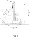
- FIG. 1 is a side view of the transport vehicle 1 according to this embodiment
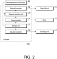
- FIG. 2 is a functional block diagram of a controller 30.
- the transport vehicle 1 according to this embodiment is an unmanned guided vehicle that autonomously travels and handles cargo, but this is merely an example, and the transport vehicle 1 according to the disclosure is not limited thereto.
- the transport vehicle 1 may be a manned/unmanned transport vehicle 1.
- the transport vehicle 1 includes a plurality of wheels 10, a vehicle body 11, a driver 12, a laser scanner 13, left and right masts 14, a lift bracket 15, left and right forks 16, an elevating unit 17, a backrest 18, a side shift unit 19, left and right carriages 20, left and right reach legs 21, left and right two-dimensional LiDAR sensors 22, left and right connecting parts 23, and the controller 30.
- the transport vehicle 1 is a reach-type forklift, this is merely an example, and the transport vehicle 1 according to the disclosure may be a counter-type forklift.
- the vehicle body 11 is arranged on the wheels 10, and the driver 12 is arranged inside the vehicle body 11.
- the driver 12 is configured to rotate and stop the wheels 10.
- the laser scanner 13 is arranged above the vehicle body 11, and rotates horizontally to emit a laser. Then, the laser scanner 13 specifies the position of a reflector arranged in the facility by scanning the reflected light of the laser, so as to specify the current position of the transport vehicle 1.
- the left and right masts 14 extend vertically and are arranged in front of the vehicle body 11.
- the lift bracket 15 has finger bars for fixing the left and right forks 16, and is configured to be raised and lowered along the left and right masts 14 by the elevating unit 17.
- the left and right forks 16 correspond to the "cargo loading unit" of the disclosure.
- the number of forks 16 is four, but may be two or six and is not particularly limited.
- the transport vehicle 1 is equipped with four forks 16, so as to scoop up two pallets (cargo) at the same time.
- the backrest 18 is formed in the shape of a frame, and is configured to extend vertically and horizontally and receive the loaded cargo W1.
- the backrest 18 shown in FIG. 3A to FIG. 3C and FIG. 5 only the outer frame is shown, and the outer frame is arranged outside the forks 16 in the left-right direction.
- the side shift unit 19 has an actuator, and is configured to move the backrest 18 together with the forks 16 in the left-right direction by the actuator.
- the side shift unit 19 is capable of adjusting the position of the fork 16 in the left-right direction with respect to the fork insertion hole of the pallet and adjusting the position for loading the cargo W1.
- the actuator may be a hydraulic actuator or an electric actuator, and is not particularly limited.
- the left and right carriages 20 are provided outside the left and right masts 14 respectively, and the left and right reach legs 21 extend forward from the vehicle body 11.
- Guides for guiding the carriages 20 are provided inside the left and right reach legs 21, and the mast 14 is moved together with the carriage 20 to an advanced position or a retracted position by a reach cylinder (not shown).
- the left and right two-dimensional LiDAR sensors 22 are configured by laser scanners, and are configured to be capable of irradiating a laser while rotating in the horizontal direction and scanning the reflected light of the laser to acquire the distances to the surrounding objects of the two-dimensional LiDAR sensors 22 by a point group PG.
- the two-dimensional LiDAR sensor 22 corresponds to the "point group acquisition unit" of the disclosure.
- the point group acquisition unit may be a three-dimensional LiDAR sensor or a three-dimensional ToF (Time of Flight) camera, and is not limited to a two-dimensional LiDAR sensor.
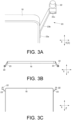
- the left and right connecting parts 23 have first end portions 23a, intermediate portions 23b, and second end portions 23c.
- the first end portions 23a are fixed to the left and right ends of the backrest 18, and the intermediate portion 23b extends obliquely behind the backrest 18 from the first end portion 23a in plan view.
- the second end portion 23c has a horizontal surface continuous from the intermediate portion 23b, and supports the two-dimensional LiDAR sensor 22 with the horizontal surface.
- the length of the intermediate portion 23b is configured such that the two-dimensional LiDAR sensor 22 supported by the second end portion 23c is positioned outside the side surface of the cargo loaded on the forks 16. That is, if the width of the backrest 18 is narrow and the cargo protrudes greatly from the backrest 18 to the left and right, the length of the intermediate portion 23b is lengthened accordingly.
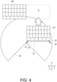
- FIG. 4 is a plan view showing a laser irradiation range LE of the two-dimensional LiDAR sensor 22
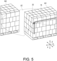
- FIG. 5 is a perspective view showing the laser irradiation range LE of the two-dimensional LiDAR sensor 22.
- FIG. 4 and FIG. 5 show the cargo W1 loaded on the forks 16 and the cargo W2 loaded adjacent to a cargo loading position P in front of the cargo W1.
- the cargo loading position P is, for example, a predetermined loading position of a mobile shelf included in a cargo handling schedule, a predetermined loading position of a loading platform of a truck T, or the like.
- the two-dimensional LiDAR sensor 22 is arranged at a position to be capable of horizontally irradiating the cargo W1 loaded on the forks 16 and the cargo loading position P with a laser. Then, the two-dimensional LiDAR sensor 22 acquires the distance to the object for each irradiation angle by irradiating the laser while rotating horizontally and receiving the reflected light. This distance data is acquired as the point group PG.
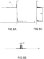
- FIG. 6A is a diagram showing the point group PG acquired by the two-dimensional LiDAR sensor 22 on the left side.
- the X-axis in FIG. 6A and FIG. 6B indicates the distance in the left-right direction and the Y-axis in FIG. 6A and FIG. 6C indicates the distance in the front-rear direction, and the intersection (origin) of the X-axis and the Y-axis indicates the position of the two-dimensional LiDAR sensor 22.
- the point group PG in the attached drawings is an image diagram for showing an example of the acquired point group PG, and is not the point group PG actually acquired. As shown in FIG. 6A , the point group PG is acquired along the end surfaces of the cargo W1 loaded on the forks 16 and the cargo W2 loaded adjacent to the cargo loading position P.
- the controller 30 is arranged inside the vehicle body 11.
- the controller 30 is configured by a computer having a storage device, an arithmetic unit, and a memory.
- the storage device stores a distance specifying program that causes the computer to operate as a distance specifying unit 36 of the disclosure.
- the controller 30 includes a storage unit 32, a travel controller 34, the distance specifying unit 36, an elevation controller 38, and a side shift controller 40.
- a cargo handling schedule is stored in the storage unit 32, and the cargo loading position P is included in the cargo handling schedule.
- the storage unit 32 also includes the positions of the left and right two-dimensional LiDAR sensors 22 and the distance from the retracted position to the advanced position of the mast 14.
- the travel controller 34 is configured to control the driver 12, and causes the transport vehicle 1 to travel to the cargo loading position P with reference to the cargo loading position P stored in the storage unit 32 and the current position acquired by the laser scanner 13.
- the distance specifying unit 36 specifies a distance D1 in the left-right direction and a distance D2 in the front-rear direction between the cargo W1 loaded on the forks 16 and the object adjacent to the cargo loading position P.
- a method of analyzing the point group PG performed by the distance specifying unit 36 is not particularly limited.
- the travel controller 34 may calculate a forward distance required for unloading based on the distances D1 and D2 between the cargo W1 and the object adjacent to the cargo loading position P, the distance from the retracted position to the advanced position of the mast 14, and the current position of the transport vehicle 1, and cause the transport vehicle 1 to advance based on the calculated distance.
- the elevation controller 38 is configured to control the elevating unit 17, and raises and lowers the forks 16 by the elevating unit 17 based on the cargo loading position P stored in the storage unit 32.
- the side shift controller 40 is configured to control the side shift unit 19, and moves the cargo W1 close to or away from the object adjacent to the cargo loading position P by the side shift unit 19 based on the distance D1 in the left-right direction between the cargo W1 loaded on the forks 16 and the object adjacent to the cargo loading position P, which is specified by the distance specifying unit 36.
- FIG. 6B and FIG. 6C show the point group PG of FIG. 6A as histograms in the left-right direction and the up-down direction.
- the distance specifying unit 36 is able to specify the area with no reflection of the laser using the frequency distribution, and calculate the length D1 of the area to specify the distance D1 between the side surface of the cargo W1 and the side surface of the cargo W2.
- the distance specifying unit 36 is able to specify the distance D2 between the front surface of the cargo W1 and the front surface of the cargo W2 by calculating the distance D2 between the two peak values.
- the distance specifying unit 36 is able to specify the distance D2 between the front surface of the cargo W1 and the front surface of the cargo W2 by calculating the distance between these boundaries.
- the distance specifying unit 36 is able to analyze the point group PG acquired by the two-dimensional LiDAR sensor 22 using the frequency distribution to specify the distance D1 in the left-right direction and the distance D2 in the front-rear direction between the cargo W1 and the object adjacent to the cargo loading position P. Since the transport vehicle 1 is capable of correcting the cargo loading position P afterward even if the mobile shelf, the truck T, or the like deviates from the predetermined position, it is possible to load the cargo W1 at an appropriate position.
- the histograms of FIG. 6B and FIG. 6C are for illustrating the frequency distribution in this specification, and there is no particular need for the distance specifying unit 36 to create histograms.
- FIG. 7A to FIG. 10C show examples of the information that the distance specifying unit 36 can acquire by frequency distribution analysis.
- FIG. 7A shows the point group PG acquired by the two-dimensional LiDAR sensor 22 when the cargo loading position P is a frame-shaped rack.
- the left side of FIG. 7A shows two point groups PG acquired by irradiating two frames with a laser.
- FIG. 7B and FIG. 7C show the acquired point groups PG by histograms in the left-right direction and the up-down direction.
- the distance specifying unit 36 specifies the distance D1 between the side surface of the frame and the side surface of the cargo W1 by calculating the length of the area with no reflection of the laser by the same method as described above. Further, the distance specifying unit 36 specifies the distance between the front surface of the frame and the front surface of the cargo W1 by calculating the distance D2 between the upper and lower two peak values by the same method as described above.
- FIG. 8A shows the point group PG acquired by the two-dimensional LiDAR sensor 22 when the position of the two-dimensional LiDAR sensor 22 is arranged at the center of the height of the backrest 18.
- the right side of FIG. 8A shows the point group PG acquired by reflection of the laser to the end portion of the backrest 18.
- the distance specifying unit 36 is capable of specifying the distances D1 and D2 by the same method.
- FIG. 9A shows the point group PG acquired by the two-dimensional LiDAR sensor 22 when there is an abnormality in the loading destination space, such as collapse of cargo.
- the upper side of FIG. 9A shows the point group PG acquired by reflection of the laser to the location where the abnormality occurs.
- FIG. 9B it is possible to specify that there is no area with no distribution in the center in the left-right direction by analyzing using the frequency distribution.
- the distance specifying unit 36 is capable of specifying that there is no gap between the cargo W1 and the cargo W2, specifically, there is no area with no reflection of the laser between the peak value on the left side and the peak value on the right side.
- the distance specifying unit 36 is capable of recognizing that there is an abnormality in the loading destination space.
- the controller 30 may stop the cargo handling operation of the transport vehicle 1.
- FIG. 10A shows the point group PG acquired by irradiating only the cargo W1 with a laser by the two-dimensional LiDAR sensor 22.
- the distance specifying unit 36 specifies the area from the two-dimensional LiDAR sensor 22 (origin) to the area with the distribution or the area to the peak value by analyzing the point group PG data using the frequency distribution.
- the distance specifying unit 36 is also capable of calculating a distance D3 in the left-right direction and a distance D4 in the front-rear direction between the two-dimensional LiDAR sensor 22 and the cargo W1 by calculating the distances D3 and D4 of the specified area.
- the distance between a surrounding object and the LiDAR sensor is specified by comparing and matching the shape and features of the object that has been specified in advance with the acquired point group PG.
- the position of the LiDAR sensor is adjusted so as to irradiate the cargo W1 with a laser and not block the laser. Therefore, with the conventional method, it is not possible to acquire the mutual positional relationship among the transport vehicle 1, the cargo W1, and the object adjacent to the cargo loading position P by only the LiDAR sensor. Thus, for the conventional method, it is necessary to separately perform other distance measurement, interference confirmation, etc., and for these purposes, it is necessary to separately arrange other sensors.
- the method of the disclosure it is possible to acquire the mutual positional relationship among the transport vehicle 1, the loaded cargo W1, and the object or cargo W2 adjacent to the cargo loading position P using only the left and right two-dimensional LiDAR sensors 22. Moreover, according to the method of the disclosure, it is possible to constantly and stably acquire the distance between the cargo W1 and the cargo W2 even when the unloading destination is a thin frame-shaped structure, when the surrounding structure including the backrest 18 is detected by the two-dimensional LiDAR sensor 22, or when there is an abnormality in the loading destination space.
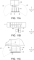
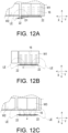
- FIG. 11A to FIG. 12C an example of a series of operations of the transport vehicle 1 according to the disclosure will be described with reference to FIG. 11A to FIG. 12C .
- the transport vehicle 1 in FIG. 11A to FIG. 12C is assumed to be a counter-type forklift.
- the position of the mast 14 in the front-rear direction does not move.
- the transport vehicle 1 is able to detect that the cargo W1 starts to slide on the forks 16.
- the transport vehicle 1 is able to detect that the cargo W1 is pressed against an object such as the front panel or the rear panel of the truck T, and stop the movement of the forks 16 after this detection to prevent damage to the front panel and the rear panel.
- the transport vehicle 1 may be configured to stop the movement of the side shift unit after detecting that the cargo W1 starts to slide on the forks 16.
- the transport vehicle 1 irradiates a laser by the two-dimensional LiDAR sensor 22 when pulling out the forks 16 from the cargo W3.
- the transport vehicle 1 analyzes the acquired point group PG by the distance specifying unit 36 using the frequency distribution to pull out the forks 16 while specifying the positional relationship between the two-dimensional LiDAR sensor 22 and the cargo W3.
- the transport vehicle 1 detects that the cargo W3 moves together with the forks 16, thereby preventing the cargo W3 from being dragged by the forks 16.
- the two-dimensional LiDAR sensor 22 is arranged at a position to be capable of irradiating the cargo W1 and the cargo loading position P with a laser, making it possible to irradiate the cargo W1 and the object (for example, cargo W2) adjacent to the cargo loading position P with a laser and detect the reflected light from the cargo W1 and the object adjacent to the cargo loading position P to acquire the point group PG.
- the transport vehicle is capable of analyzing the acquired point group PG by the distance specifying unit 36 and specifying the distances D1 and D2 between the cargo W1 and the cargo W2, so it is possible to correct the cargo loading position P afterward and appropriately perform cargo handling work even if the mobile shelf, the truck T, or the like deviates from the predetermined position.
- the storage unit 32 also stores the position of the two-dimensional LiDAR sensor 22, and the distance specifying unit 36 is capable of analyzing the acquired point group PG to specify not only the distances D1 and D2 between the cargo W1 and the cargo W2 but also the distances D3 and D4 between the cargo W1 and the two-dimensional LiDAR sensor 22. That is, the transport vehicle 1 is capable of specifying three relative positional relationships among the cargo W1, the cargo W2, and the two-dimensional LiDAR sensor 22 (transport vehicle 1). As a result, the transport vehicle 1 is capable of performing the series of operations (1) to (6) described above.
- the disclosure is not limited to the above embodiment.
- the transport vehicle according to the disclosure may be implemented according to the following modified example.
- the second end portion 23c of the connecting part 23 is not necessarily positioned above the backrest 18.
- the point group PG acquired by the two-dimensional LiDAR sensor 22 becomes the point group PG shown in FIG. 8A , and as already described, the distance specifying unit 36 is capable of specifying the distance between the cargo W1 and the cargo W2.
- the first end portion 23a of the connecting part 23 may be provided at the upper end of the backrest 18.
- the two-dimensional LiDAR sensor 22 may be fixed to the vehicle body 11 and the finger bar, for example, as long as the two-dimensional LiDAR sensor 22 is arranged at a position to be capable of irradiating the cargo W1 loaded on the cargo loading unit 16 and the object adjacent to the cargo loading position P with a laser, or the first end portion 23a of the connecting part 23 may be fixed to the side surface (see FIG. 1 ) of a vertical unit 16a of the fork 16, which extends in the up-down direction.
- the two-dimensional LiDAR sensor 22 may be fixed to the vehicle body 11, the vertical unit 16a of the fork 16, and the finger bar via the connecting part.
- the cargo loading unit may be configured by a platen instead of the fork 16, for example.
Landscapes
- Engineering & Computer Science (AREA)
- Transportation (AREA)
- Structural Engineering (AREA)
- Civil Engineering (AREA)
- Life Sciences & Earth Sciences (AREA)
- Geology (AREA)
- Mechanical Engineering (AREA)
- Chemical & Material Sciences (AREA)
- Combustion & Propulsion (AREA)
- Forklifts And Lifting Vehicles (AREA)
- Control Of Position, Course, Altitude, Or Attitude Of Moving Bodies (AREA)
Description
- The disclosure relates to a transport vehicle, a distance specifying method, and a distance specifying program.
- Conventionally, there is an unmanned guided vehicle that autonomously travels and handles cargo, as shown in
Patent Literature 1. The unmanned guided vehicle disclosed inPatent Literature 1 includes forks, an elevating device for raising and lowering the forks, and a laser scanner for detecting the position of the vehicle itself. The unmanned guided vehicle is configured to move to a predetermined cargo handling position while detecting its own position and raise and lower the forks to perform cargo handling work. - As disclosed in
Patent Literature 1, the unmanned guided vehicle may perform cargo handling on a mobile shelf. Unlike a fixed shelf, the mobile shelf moves, but the mobile shelf may deviate from a predetermined movement position during the movement. As a result, a deviation occurs between the predetermined cargo handling position and the mobile shelf, but the unmanned transport system ofPatent Literature 1 does not take this deviation into consideration. In addition, when cargo handling work is performed on a truck that has stopped at a predetermined position, the truck may still deviate from the predetermined standby position, and in this case, there is also a deviation from the predetermined cargo handling position. If the cargo handling position is determined on the assumption that the mobile shelf or the truck will deviate, there is a problem that the cargo cannot be loaded with the space therebetween closed. In order to solve this problem, it is preferable to adjust the cargo loading position after the unmanned guided vehicle arrives at the predetermined cargo handling position, but it is not easy and difficult to recognize how much the mobile shelf, truck, or the like has deviated from the predetermined position. - Document
US 2021/276842 A1 , discloses a transport vehicle, comprising a cargo loading unit, a point group acquisition unit that is arranged at a position to be capable of irradiating a cargo loading position with a laser, and which acquires a point group by horizontally irradiating the laser and it further comprises a distance specifying unit. - [Patent Literature 1]
Japanese Patent Application Laid-Open No. 2020-030642 - Accordingly, the disclosure provides a transport vehicle that is capable of correcting the cargo loading position afterward even if the mobile shelf, truck, or the like deviates from a predetermined position.
- In order to solve the above problem, a transport vehicle according to the disclosure includes: a cargo loading unit; a point group acquisition unit that is arranged at a position to be capable of irradiating cargo loaded on the cargo loading unit and a cargo loading position with a laser, and acquires a point group by horizontally irradiating the laser; and a distance specifying unit that specifies a distance in a left-right direction between the cargo loaded on the cargo loading unit and an object adjacent to the cargo loading position based on the acquired point group.
- For example, the transport vehicle is a forklift and includes a backrest, and the point group acquisition unit is provided in the backrest.
- The transport vehicle preferably includes: a connecting part, and the connecting part is connected to the backrest and the point group acquisition unit, and arranges the point group acquisition unit obliquely behind either a left or right end portion of the backrest in plan view.
- In the transport vehicle, preferably, the connecting part has a first end portion fixed to either the left or right end portion or an upper end of the backrest, in intermediate portion extending obliquely behind the backrest from the first end portion in the plan view and a second end portion continuing from the intermediate portion and supporting the point group acquisition unit.
- In the transport vehicle, preferably, the distance specifying unit further specifies a distance in a front-rear direction between the cargo loaded on the cargo loading unit and the object adjacent to the cargo loading position based on the acquired point group.
- In order to solve the above problem, a distance specifying method according to the disclosure is for specifying a distance in a left-right direction between cargo loaded on a cargo loading unit of a transport vehicle and an object adjacent to a cargo loading position. The distance specifying method includes: a step of acquiring a point group by horizontally irradiating the cargo loaded on the cargo loading unit and the object adjacent to the cargo loading position with a laser; and a step of specifying the distance in the left-right direction between the cargo loaded on the cargo loading unit and the object adjacent to the cargo loading position based on the acquired point group.
- In order to solve the above problem, a distance specifying method according to the disclosure is for specifying a distance in a front-rear direction between cargo loaded on a cargo loading unit of a transport vehicle and an object adjacent to a cargo loading position. The distance specifying method includes: a step of acquiring a point group by horizontally irradiating the cargo loaded on the cargo loading unit and the object adjacent to the cargo loading position with a laser; and a step of specifying the distance in the front-rear direction between the cargo loaded on the cargo loading unit and the object adjacent to the cargo loading position based on the acquired point group.
- In order to solve the above problem, a distance specifying program according to the disclosure is for a computer of a transport vehicle, which includes: a cargo loading unit; a point group acquisition unit that is configured to be capable of horizontally irradiating cargo loaded on the cargo loading unit and a cargo loading position with a laser, and acquires a point group; and the computer, to perform a step of specifying a distance between the cargo loaded on the cargo loading unit and an object adjacent to the cargo loading position based on the acquired point group.
- Effects
- Since the transport vehicle according to the disclosure is capable of specifying the distance in the left-right direction between the cargo loaded on the cargo loading unit and the object adjacent to the cargo loading position, it is possible to correct the cargo loading position afterward even if the mobile shelf, truck, or the like deviates from the predetermined position.
-
-
FIG. 1 is a side view of the cargo handling vehicle according to an embodiment of the disclosure. -
FIG. 2 is a functional block diagram of the controller. -
FIG. 3A to FIG. 3C show the connecting part, whereinFIG. 3A is a perspective view seen from the front top,FIG. 3B is a plan view, andFIG. 3C is a front view. -
FIG. 4 is a plan view showing laser irradiation of the two-dimensional LiDAR sensor. -
FIG. 5 is a perspective view showing laser irradiation of the two-dimensional LiDAR sensor. -
FIG. 6A is a diagram showing the point group acquired by the two-dimensional LiDAR sensor on the left side,FIG. 6B is a diagram in which the point group ofFIG. 6A is displayed as a histogram in the left-right direction, andFIG. 6C is a diagram in which the point group ofFIG. 6A is displayed as a histogram in the front-rear direction. -
FIG. 7A is a diagram showing another point group acquired by the two-dimensional LiDAR sensor on the left side,FIG. 7B is a diagram in which the point group ofFIG. 7A is displayed as a histogram in the left-right direction, andFIG. 7C is a diagram in which the point group ofFIG. 7A is displayed as a histogram in the front-rear direction. -
FIG. 8A is a diagram showing yet another point group acquired by the two-dimensional LiDAR sensor on the left side,FIG. 8B is a diagram in which the point group ofFIG. 8A is displayed as a histogram in the left-right direction, andFIG. 8C is a diagram in which the point group ofFIG. 8A is displayed as a histogram in the front-rear direction. -
FIG. 9A is a diagram showing yet another point group acquired by the two-dimensional LiDAR sensor on the left side,FIG. 9B is a diagram in which the point group ofFIG. 9A is displayed as a histogram in the left-right direction, andFIG. 9C is a diagram in which the point group ofFIG. 9A is displayed as a histogram in the front-rear direction. -
FIG. 10A is a diagram showing yet another point group acquired by the two-dimensional LiDAR sensor on the left side,FIG. 10B is a diagram in which the point group ofFIG. 10A is displayed as a histogram in the left-right direction, andFIG. 10C is a diagram in which the point group ofFIG. 10A is displayed as a histogram in the front-rear direction. -
FIG. 11A, FIG. 11B, and FIG. 11C are views respectively showing a series of operations of the transport vehicle. -
FIG. 12A, FIG. 12B, and FIG. 12C are views respectively further showing a series of operations of the transport vehicle. - Hereinafter, an embodiment of a transport vehicle, a connecting part, a distance specifying method, and a distance specifying program according to the disclosure will be described with reference to the accompanying drawings. In the drawings, a double-headed arrow X indicates the left-right direction, a double-headed arrow Y indicates the front-rear direction, and a double-headed arrow Z indicates the up-down direction.
-
FIG. 1 is a side view of thetransport vehicle 1 according to this embodiment, andFIG. 2 is a functional block diagram of acontroller 30. Thetransport vehicle 1 according to this embodiment is an unmanned guided vehicle that autonomously travels and handles cargo, but this is merely an example, and thetransport vehicle 1 according to the disclosure is not limited thereto. For example, thetransport vehicle 1 may be a manned/unmanned transport vehicle 1. - As shown in
FIG. 1 andFIG. 2 , thetransport vehicle 1 includes a plurality ofwheels 10, avehicle body 11, adriver 12, alaser scanner 13, left andright masts 14, alift bracket 15, left andright forks 16, an elevatingunit 17, abackrest 18, aside shift unit 19, left andright carriages 20, left and right reachlegs 21, left and right two-dimensional LiDAR sensors 22, left and right connectingparts 23, and thecontroller 30. Although thetransport vehicle 1 is a reach-type forklift, this is merely an example, and thetransport vehicle 1 according to the disclosure may be a counter-type forklift. - The
vehicle body 11 is arranged on thewheels 10, and thedriver 12 is arranged inside thevehicle body 11. Thedriver 12 is configured to rotate and stop thewheels 10. - The
laser scanner 13 is arranged above thevehicle body 11, and rotates horizontally to emit a laser. Then, thelaser scanner 13 specifies the position of a reflector arranged in the facility by scanning the reflected light of the laser, so as to specify the current position of thetransport vehicle 1. - The left and
right masts 14 extend vertically and are arranged in front of thevehicle body 11. Thelift bracket 15 has finger bars for fixing the left andright forks 16, and is configured to be raised and lowered along the left andright masts 14 by the elevatingunit 17. The left andright forks 16 correspond to the "cargo loading unit" of the disclosure. In this embodiment, the number offorks 16 is four, but may be two or six and is not particularly limited. Thetransport vehicle 1 is equipped with fourforks 16, so as to scoop up two pallets (cargo) at the same time. - The
backrest 18 is formed in the shape of a frame, and is configured to extend vertically and horizontally and receive the loaded cargo W1. For thebackrest 18 shown inFIG. 3A to FIG. 3C andFIG. 5 , only the outer frame is shown, and the outer frame is arranged outside theforks 16 in the left-right direction. - The
side shift unit 19 has an actuator, and is configured to move thebackrest 18 together with theforks 16 in the left-right direction by the actuator. Thus, theside shift unit 19 is capable of adjusting the position of thefork 16 in the left-right direction with respect to the fork insertion hole of the pallet and adjusting the position for loading the cargo W1. The actuator may be a hydraulic actuator or an electric actuator, and is not particularly limited. - The left and
right carriages 20 are provided outside the left andright masts 14 respectively, and the left and right reachlegs 21 extend forward from thevehicle body 11. Guides for guiding thecarriages 20 are provided inside the left and right reachlegs 21, and themast 14 is moved together with thecarriage 20 to an advanced position or a retracted position by a reach cylinder (not shown). - The left and right two-
dimensional LiDAR sensors 22 are configured by laser scanners, and are configured to be capable of irradiating a laser while rotating in the horizontal direction and scanning the reflected light of the laser to acquire the distances to the surrounding objects of the two-dimensional LiDAR sensors 22 by a point group PG. The two-dimensional LiDAR sensor 22 corresponds to the "point group acquisition unit" of the disclosure. For example, instead of the two-dimensional LiDAR sensor 22, the point group acquisition unit may be a three-dimensional LiDAR sensor or a three-dimensional ToF (Time of Flight) camera, and is not limited to a two-dimensional LiDAR sensor. - As shown in
FIG. 1 andFIG. 3A to FIG. 3C , the left and right connectingparts 23 havefirst end portions 23a,intermediate portions 23b, andsecond end portions 23c. - The
first end portions 23a are fixed to the left and right ends of thebackrest 18, and theintermediate portion 23b extends obliquely behind thebackrest 18 from thefirst end portion 23a in plan view. Thesecond end portion 23c has a horizontal surface continuous from theintermediate portion 23b, and supports the two-dimensional LiDAR sensor 22 with the horizontal surface. - The length of the
intermediate portion 23b is configured such that the two-dimensional LiDAR sensor 22 supported by thesecond end portion 23c is positioned outside the side surface of the cargo loaded on theforks 16. That is, if the width of thebackrest 18 is narrow and the cargo protrudes greatly from thebackrest 18 to the left and right, the length of theintermediate portion 23b is lengthened accordingly. -
FIG. 4 is a plan view showing a laser irradiation range LE of the two-dimensional LiDAR sensor 22, andFIG. 5 is a perspective view showing the laser irradiation range LE of the two-dimensional LiDAR sensor 22. Further,FIG. 4 andFIG. 5 show the cargo W1 loaded on theforks 16 and the cargo W2 loaded adjacent to a cargo loading position P in front of the cargo W1. The cargo loading position P is, for example, a predetermined loading position of a mobile shelf included in a cargo handling schedule, a predetermined loading position of a loading platform of a truck T, or the like. - As shown in
FIG. 4 andFIG. 5 , the two-dimensional LiDAR sensor 22 is arranged at a position to be capable of horizontally irradiating the cargo W1 loaded on theforks 16 and the cargo loading position P with a laser. Then, the two-dimensional LiDAR sensor 22 acquires the distance to the object for each irradiation angle by irradiating the laser while rotating horizontally and receiving the reflected light. This distance data is acquired as the point group PG. -
FIG. 6A is a diagram showing the point group PG acquired by the two-dimensional LiDAR sensor 22 on the left side. The X-axis inFIG. 6A and FIG. 6B indicates the distance in the left-right direction and the Y-axis inFIG. 6A and FIG. 6C indicates the distance in the front-rear direction, and the intersection (origin) of the X-axis and the Y-axis indicates the position of the two-dimensional LiDAR sensor 22. In addition, the point group PG in the attached drawings is an image diagram for showing an example of the acquired point group PG, and is not the point group PG actually acquired. As shown inFIG. 6A , the point group PG is acquired along the end surfaces of the cargo W1 loaded on theforks 16 and the cargo W2 loaded adjacent to the cargo loading position P. - As shown in
FIG. 1 , thecontroller 30 is arranged inside thevehicle body 11. Thecontroller 30 is configured by a computer having a storage device, an arithmetic unit, and a memory. The storage device stores a distance specifying program that causes the computer to operate as adistance specifying unit 36 of the disclosure. - As shown in
FIG. 2 , thecontroller 30 includes astorage unit 32, atravel controller 34, thedistance specifying unit 36, anelevation controller 38, and aside shift controller 40. - A cargo handling schedule is stored in the
storage unit 32, and the cargo loading position P is included in the cargo handling schedule. Thestorage unit 32 also includes the positions of the left and right two-dimensional LiDAR sensors 22 and the distance from the retracted position to the advanced position of themast 14. - The
travel controller 34 is configured to control thedriver 12, and causes thetransport vehicle 1 to travel to the cargo loading position P with reference to the cargo loading position P stored in thestorage unit 32 and the current position acquired by thelaser scanner 13. - Based on the acquired point group PG, the
distance specifying unit 36 specifies a distance D1 in the left-right direction and a distance D2 in the front-rear direction between the cargo W1 loaded on theforks 16 and the object adjacent to the cargo loading position P. A method of analyzing the point group PG performed by thedistance specifying unit 36 is not particularly limited. - The
travel controller 34 may calculate a forward distance required for unloading based on the distances D1 and D2 between the cargo W1 and the object adjacent to the cargo loading position P, the distance from the retracted position to the advanced position of themast 14, and the current position of thetransport vehicle 1, and cause thetransport vehicle 1 to advance based on the calculated distance. - The
elevation controller 38 is configured to control the elevatingunit 17, and raises and lowers theforks 16 by the elevatingunit 17 based on the cargo loading position P stored in thestorage unit 32. - The
side shift controller 40 is configured to control theside shift unit 19, and moves the cargo W1 close to or away from the object adjacent to the cargo loading position P by theside shift unit 19 based on the distance D1 in the left-right direction between the cargo W1 loaded on theforks 16 and the object adjacent to the cargo loading position P, which is specified by thedistance specifying unit 36. Thus, it is possible to load the cargo W1 with a closed space between the cargo W1 and the cargo W2 and to avoid a state where the cargo W1 overlaps. - Next, the method by which the
distance specifying unit 36 specifies the distance D1 in the left-right direction between the cargo W1 and the cargo W2 will be described with reference toFIG. 6A to FIG. 6C. FIG. 6B and FIG. 6C show the point group PG ofFIG. 6A as histograms in the left-right direction and the up-down direction. - As shown in
FIG. 6B , according to the frequency distribution on the X-axis, there is a range with no distribution in the middle. This range indicates areas where reflection of the laser received by the two-dimensional LiDAR sensor 22 is extremely low or unavailable compared to other areas. Therefore, thedistance specifying unit 36 is able to specify the area with no reflection of the laser using the frequency distribution, and calculate the length D1 of the area to specify the distance D1 between the side surface of the cargo W1 and the side surface of the cargo W2. - Furthermore, as shown in
FIG. 6C , according to the frequency distribution on the Y-axis, it can be seen that there are two peak values on the upper side and the lower side. Accordingly, thedistance specifying unit 36 is able to specify the distance D2 between the front surface of the cargo W1 and the front surface of the cargo W2 by calculating the distance D2 between the two peak values. Alternatively, it can be seen that there is a boundary between the lower side of the peak value on the upper side and the lower side of the peak value on the lower side where the distribution of the point group PG disappears. Therefore, thedistance specifying unit 36 is able to specify the distance D2 between the front surface of the cargo W1 and the front surface of the cargo W2 by calculating the distance between these boundaries. - In this way, the
distance specifying unit 36 is able to analyze the point group PG acquired by the two-dimensional LiDAR sensor 22 using the frequency distribution to specify the distance D1 in the left-right direction and the distance D2 in the front-rear direction between the cargo W1 and the object adjacent to the cargo loading position P. Since thetransport vehicle 1 is capable of correcting the cargo loading position P afterward even if the mobile shelf, the truck T, or the like deviates from the predetermined position, it is possible to load the cargo W1 at an appropriate position. The histograms ofFIG. 6B and FIG. 6C are for illustrating the frequency distribution in this specification, and there is no particular need for thedistance specifying unit 36 to create histograms. -
FIG. 7A to FIG. 10C show examples of the information that thedistance specifying unit 36 can acquire by frequency distribution analysis. -
FIG. 7A shows the point group PG acquired by the two-dimensional LiDAR sensor 22 when the cargo loading position P is a frame-shaped rack. The left side ofFIG. 7A shows two point groups PG acquired by irradiating two frames with a laser. In addition,FIG. 7B and FIG. 7C show the acquired point groups PG by histograms in the left-right direction and the up-down direction. Thedistance specifying unit 36 specifies the distance D1 between the side surface of the frame and the side surface of the cargo W1 by calculating the length of the area with no reflection of the laser by the same method as described above. Further, thedistance specifying unit 36 specifies the distance between the front surface of the frame and the front surface of the cargo W1 by calculating the distance D2 between the upper and lower two peak values by the same method as described above. - In addition,
FIG. 8A shows the point group PG acquired by the two-dimensional LiDAR sensor 22 when the position of the two-dimensional LiDAR sensor 22 is arranged at the center of the height of thebackrest 18. The right side ofFIG. 8A shows the point group PG acquired by reflection of the laser to the end portion of thebackrest 18. However, even in this case, it is still possible to specify the area with no reflection of the laser in the center in the left-right direction by analyzing using the frequency distribution, as shown inFIG. 8B and FIG. 8C , and it is possible to specify the peak on the upper side and the peak on the lower side in the up-down direction. Thus, thedistance specifying unit 36 is capable of specifying the distances D1 and D2 by the same method. - Further,
FIG. 9A shows the point group PG acquired by the two-dimensional LiDAR sensor 22 when there is an abnormality in the loading destination space, such as collapse of cargo. The upper side ofFIG. 9A shows the point group PG acquired by reflection of the laser to the location where the abnormality occurs. In this case, as shown inFIG. 9B , it is possible to specify that there is no area with no distribution in the center in the left-right direction by analyzing using the frequency distribution. In this way, by analyzing using the frequency distribution, thedistance specifying unit 36 is capable of specifying that there is no gap between the cargo W1 and the cargo W2, specifically, there is no area with no reflection of the laser between the peak value on the left side and the peak value on the right side. Thereby, thedistance specifying unit 36 is capable of recognizing that there is an abnormality in the loading destination space. In this case, thecontroller 30 may stop the cargo handling operation of thetransport vehicle 1. -
FIG. 10A shows the point group PG acquired by irradiating only the cargo W1 with a laser by the two-dimensional LiDAR sensor 22. As shown inFIG. 10B and FIG. 10C , thedistance specifying unit 36 specifies the area from the two-dimensional LiDAR sensor 22 (origin) to the area with the distribution or the area to the peak value by analyzing the point group PG data using the frequency distribution. Thereby, thedistance specifying unit 36 is also capable of calculating a distance D3 in the left-right direction and a distance D4 in the front-rear direction between the two-dimensional LiDAR sensor 22 and the cargo W1 by calculating the distances D3 and D4 of the specified area. - In the analysis using a LiDAR sensor, conventionally the distance between a surrounding object and the LiDAR sensor is specified by comparing and matching the shape and features of the object that has been specified in advance with the acquired point group PG. For this method, it is difficult to stably acquire the distance to the surrounding object when the unloading destination is a thin frame-shaped structure, when the surrounding structure including the
backrest 18 is detected by the LiDAR sensor, or when there is an abnormality in the loading destination space. - Besides, since the conventional analysis using a LiDAR sensor adopts a method of recognizing the shape and features of an object that has been specified in advance, the position of the LiDAR sensor is adjusted so as to irradiate the cargo W1 with a laser and not block the laser. Therefore, with the conventional method, it is not possible to acquire the mutual positional relationship among the
transport vehicle 1, the cargo W1, and the object adjacent to the cargo loading position P by only the LiDAR sensor. Thus, for the conventional method, it is necessary to separately perform other distance measurement, interference confirmation, etc., and for these purposes, it is necessary to separately arrange other sensors. - In contrast, according to the method of the disclosure, it is possible to acquire the mutual positional relationship among the
transport vehicle 1, the loaded cargo W1, and the object or cargo W2 adjacent to the cargo loading position P using only the left and right two-dimensional LiDAR sensors 22. Moreover, according to the method of the disclosure, it is possible to constantly and stably acquire the distance between the cargo W1 and the cargo W2 even when the unloading destination is a thin frame-shaped structure, when the surrounding structure including thebackrest 18 is detected by the two-dimensional LiDAR sensor 22, or when there is an abnormality in the loading destination space. - Next, an example of a series of operations of the
transport vehicle 1 according to the disclosure will be described with reference toFIG. 11A to FIG. 12C . In this description, thetransport vehicle 1 inFIG. 11A to FIG. 12C is assumed to be a counter-type forklift. Thus, it is assumed that the position of themast 14 in the front-rear direction does not move. - (1) (1-1) As shown in
FIG. 11A , before thetransport vehicle 1 scoops up the cargo W3, the left and right two-dimensional LiDAR sensors 22 irradiate the cargo W3 with lasers.- (1-2) Next, the
transport vehicle 1 analyzes the acquired point group PG by thedistance specifying unit 36 using the frequency distribution to specify the positions of the left and right ends of the cargo W3 and the position of the center of the cargo W3 in the left-right direction. - (1-3) Next, the
transport vehicle 1 calculates the distance D5 between the position of the center of the cargo W3 in the left-right direction and the position of the center of thebackrest 18 in the left-right direction by thedistance specifying unit 36. - (1-4) Furthermore, based on the calculated distance D5, the
transport vehicle 1 moves theforks 16 in the left-right direction by theside shift unit 19, thereby correcting the center deviation between theforks 16 and the cargo W3.
transport vehicle 1 is a side fork vehicle, thetransport vehicle 1 is capable of correcting the center deviation between theforks 16 and the cargo W3 by moving thevehicle body 11 by thetravel controller 34 based on the specified distance D5. - (1-2) Next, the
- (2) (2-1) Next, the
transport vehicle 1 scoops up the cargo W3 (W1) and transports it to the truck T, and as shown inFIG. 11B , travels in parallel to the loading platform of the truck T while irradiating the loading platform of the truck T with a laser by the two-dimensional LiDAR sensor 22 on the side of the truck T.- (2-2) Next, the
transport vehicle 1 analyzes the acquired point group PG by thedistance specifying unit 36 using the frequency distribution to detect the side surface of the object (cargo W2) adjacent to the cargo loading position P on the loading platform, and specify the mutual positional relationship among the position of the detected side surface, the position of the two-dimensional LiDAR sensor 22, and the position of the cargo W1. - (2-3) Next, when detecting the side surface of this object, the
transport vehicle 1 changes the direction to the side of the truck T by thetravel controller 34 based on the positional relationship among the position of the specified side surface, the position of the two-dimensional LiDAR sensor 22, and the cargo W1.
- (2-2) Next, the
- (3) (3-1) Next, as shown in
FIG. 11C , before thetransport vehicle 1 advances toward the cargo loading position P, the two-dimensional LiDAR sensor 22 irradiates a laser in the horizontal direction.
(3-2) Next, thetransport vehicle 1 analyzes the acquired point group PG by thedistance specifying unit 36 using the frequency distribution to specify the distance D1 between the cargo W1 and the cargo W2, thereby determining whether the cargo W1 interferes with the cargo W2. At this time, as described above, thetransport vehicle 1 may stop cargo handling when specifying that an abnormality has occurred. - (4) (4-1) Next, the
transport vehicle 1 advances to the cargo loading position P by thetravel controller 34 based on the distance D2 in the front-rear direction between the cargo W1 and the cargo W2 specified by thedistance specifying unit 36.- (4-2) Next, as shown in
FIG. 12A , thetransport vehicle 1 irradiates a laser by the two-dimensional LiDAR sensor 22 before unloading the cargo W1. - (4-3) Next, the
transport vehicle 1 specifies the distance D1 between the cargo W1 and the cargo W2 by analyzing the acquired point group PG by thedistance specifying unit 36 using the frequency distribution. - (4-4) Next, the
transport vehicle 1 specifies the control amount of theside shift unit 19 by theside shift controller 40 based on the specified distance D1.
transport vehicle 1 is able to appropriately bring the cargo W1 close to the cargo W2 by theside shift unit 19. - (4-2) Next, as shown in
- (5) (5-1) Next, as shown in
FIG. 12B , thetransport vehicle 1 irradiates a laser with the two-dimensional LiDAR sensor 22 when moving theforks 16 to the left by theside shift unit 19.- (5-2) Next, the
transport vehicle 1 analyzes the acquired point group PG by thedistance specifying unit 36 using the frequency distribution to calculate the distances D3 and D4 in the left-right direction and the front-rear direction between the two-dimensional LiDAR sensor 22 and the cargo W1, and move theforks 16 while specifying the positional relationship between the two-dimensional LiDAR sensor 22 and the cargo W1. - (5-3) At this time, while moving by the
side shift unit 19, thetransport vehicle 1 determines by thedistance specifying unit 36 whether the positional relationship between the two-dimensional LiDAR sensor 22 and the cargo W1 changes.
- (5-2) Next, the
- Thereby, the
transport vehicle 1 is able to detect that the cargo W1 starts to slide on theforks 16. Thus, for example, thetransport vehicle 1 is able to detect that the cargo W1 is pressed against an object such as the front panel or the rear panel of the truck T, and stop the movement of theforks 16 after this detection to prevent damage to the front panel and the rear panel. - On the other hand, if it is desired to press the cargo W1 against the cargo W2, the
transport vehicle 1 may be configured to stop the movement of the side shift unit after detecting that the cargo W1 starts to slide on theforks 16. - (6) (6-1) Next, as shown in
FIG. 12C , thetransport vehicle 1 irradiates a laser by the two-dimensional LiDAR sensor 22 when pulling out theforks 16 from the cargo W3. (6-2) Next, thetransport vehicle 1 analyzes the acquired point group PG by thedistance specifying unit 36 using the frequency distribution to pull out theforks 16 while specifying the positional relationship between the two-dimensional LiDAR sensor 22 and the cargo W3. - As a result, the
transport vehicle 1 detects that the cargo W3 moves together with theforks 16, thereby preventing the cargo W3 from being dragged by theforks 16. - As described above, the two-
dimensional LiDAR sensor 22 is arranged at a position to be capable of irradiating the cargo W1 and the cargo loading position P with a laser, making it possible to irradiate the cargo W1 and the object (for example, cargo W2) adjacent to the cargo loading position P with a laser and detect the reflected light from the cargo W1 and the object adjacent to the cargo loading position P to acquire the point group PG. Thus, the transport vehicle is capable of analyzing the acquired point group PG by thedistance specifying unit 36 and specifying the distances D1 and D2 between the cargo W1 and the cargo W2, so it is possible to correct the cargo loading position P afterward and appropriately perform cargo handling work even if the mobile shelf, the truck T, or the like deviates from the predetermined position. - Moreover, the
storage unit 32 also stores the position of the two-dimensional LiDAR sensor 22, and thedistance specifying unit 36 is capable of analyzing the acquired point group PG to specify not only the distances D1 and D2 between the cargo W1 and the cargo W2 but also the distances D3 and D4 between the cargo W1 and the two-dimensional LiDAR sensor 22. That is, thetransport vehicle 1 is capable of specifying three relative positional relationships among the cargo W1, the cargo W2, and the two-dimensional LiDAR sensor 22 (transport vehicle 1). As a result, thetransport vehicle 1 is capable of performing the series of operations (1) to (6) described above. - Although an embodiment of the transport vehicle, the connecting part, the distance specifying method, and the distance specifying program of the disclosure has been described above, the disclosure is not limited to the above embodiment. For example, the transport vehicle according to the disclosure may be implemented according to the following modified example.
- The
second end portion 23c of the connectingpart 23 is not necessarily positioned above thebackrest 18. In this case, the point group PG acquired by the two-dimensional LiDAR sensor 22 becomes the point group PG shown inFIG. 8A , and as already described, thedistance specifying unit 36 is capable of specifying the distance between the cargo W1 and the cargo W2. Further, thefirst end portion 23a of the connectingpart 23 may be provided at the upper end of thebackrest 18. - The two-
dimensional LiDAR sensor 22 may be fixed to thevehicle body 11 and the finger bar, for example, as long as the two-dimensional LiDAR sensor 22 is arranged at a position to be capable of irradiating the cargo W1 loaded on thecargo loading unit 16 and the object adjacent to the cargo loading position P with a laser, or thefirst end portion 23a of the connectingpart 23 may be fixed to the side surface (seeFIG. 1 ) of avertical unit 16a of thefork 16, which extends in the up-down direction. Alternatively, the two-dimensional LiDAR sensor 22 may be fixed to thevehicle body 11, thevertical unit 16a of thefork 16, and the finger bar via the connecting part. - The cargo loading unit may be configured by a platen instead of the
fork 16, for example. -
- W1 cargo loaded on the cargo loading unit
- W2 cargo loaded adjacent to the cargo loading position
- W3 cargo loaded at the cargo loading position
- D1 distance in the left-right direction
- D2 distance in the front-rear direction
- P cargo loading position
- LE laser irradiation range
- PG point group
- T truck
- 1 transport vehicle
- 10 wheel
- 11 vehicle body
- 12 driver
- 13 laser scanner
- 14 mast
- 15 lift bracket
- 16 fork (cargo loading unit)
- 16a vertical unit
- 17 elevating unit
- 18 backrest
- 19 side shift unit
- 20 carriage
- 21 reach leg
- 22 two-dimensional LiDAR sensor (point group acquisition unit)
- 23 connecting part
- 23a first end portion
- 23b intermediate portion
- 23c second end portion
- 30 controller
- 32 storage unit
- 34 travel controller
- 36 distance specifying unit
- 38 elevation controller
- 40 side shift controller
Claims (8)
- A transport vehicle (1), comprising:a cargo loading unit (16); anda point group acquisition unit (22) that is arranged at a position to be capable of irradiating cargo loaded on the cargo loading unit and a cargo loading position (P) with a laser, and acquires a point group (PG) by horizontally irradiating the laser;wherein the transport vehicle further comprising:
a distance specifying unit (36) that specifies a distance in a left-right direction between the cargo loaded on the cargo loading unit and an object adjacent to the cargo loading position based on the acquired point group. - The transport vehicle according to claim 1, wherein the transport vehicle is a forklift and comprises a backrest (18), and
the point group acquisition unit is provided in the backrest. - The transport vehicle according to claim 2, further comprising a connecting part (23),
wherein the connecting part is connected to the backrest and the point group acquisition unit, and arranges the point group acquisition unit obliquely behind either a left or right end portion of the backrest in plan view. - The transport vehicle according to claim 3, wherein the connecting part comprising:a first end portion (23a) fixed to either the left or right end portion or an upper end of the backrest (18);an intermediate portion (23b) extending obliquely behind the backrest from the first end portion in the plan view; anda second end portion (23c) continuing from the intermediate portion and supporting the point group acquisition unit (22).
- The transport vehicle according to claim 1, wherein the distance specifying unit further specifies a distance in a front-rear direction between the cargo loaded on the cargo loading unit and the object adjacent to the cargo loading position based on the acquired point group.
- A distance specifying method for specifying a distance in a left-right direction between cargo loaded on a cargo loading unit (16) of a transport vehicle (1) and an object adjacent to a cargo loading position (P), the distance specifying method comprising:a step of acquiring a point group (PG) by horizontally irradiating the cargo loaded on the cargo loading unit and the object adjacent to the cargo loading position with a laser; andwherein the method further comprising:
a step of specifying the distance in the left-right direction between the cargo loaded on the cargo loading unit and the object adjacent to the cargo loading position based on the acquired point group. - A distance specifying method for specifying a distance in a front-rear direction between cargo loaded on a cargo loading unit (16) of a transport vehicle (1) and an object adjacent to a cargo loading position (P), the distance specifying method comprising:a step of acquiring a point group (PG) by horizontally irradiating the cargo loaded on the cargo loading unit and the object adjacent to the cargo loading position with a laser; andwherein the method further comprising:
a step of specifying the distance in the front-rear direction between the cargo loaded on the cargo loading unit and the object adjacent to the cargo loading position based on the acquired point group. - A distance specifying program, for a computer (30) of a transport vehicle (1) which comprises:a cargo loading unit (16);a point group acquisition unit (22) that is configured to be capable of horizontally irradiating cargo loaded on the cargo loading unit and a cargo loading position (P) with a laser, and acquires a point group (PG); andthe distance specifying program causes the computer to operate as a distance specifying unit and to perform a step of specifying a distance between the cargo loaded on the cargo loading unit and an object adjacent to the cargo loading position based on the acquired point group.
Applications Claiming Priority (1)
| Application Number | Priority Date | Filing Date | Title |
|---|---|---|---|
| JP2023052776A JP7693264B2 (en) | 2023-03-29 | 2023-03-29 | Transport vehicle, connector, distance determination method, and distance determination program |
Publications (2)
| Publication Number | Publication Date |
|---|---|
| EP4438544A1 EP4438544A1 (en) | 2024-10-02 |
| EP4438544B1 true EP4438544B1 (en) | 2025-04-02 |
Family
ID=87933912
Family Applications (1)
| Application Number | Title | Priority Date | Filing Date |
|---|---|---|---|
| EP23195451.2A Active EP4438544B1 (en) | 2023-03-29 | 2023-09-05 | Transport vehicle, connecting part, distance specifying method, and distance specifying program |
Country Status (4)
| Country | Link |
|---|---|
| US (1) | US12415711B2 (en) |
| EP (1) | EP4438544B1 (en) |
| JP (1) | JP7693264B2 (en) |
| CN (1) | CN118723868A (en) |
Families Citing this family (1)
| Publication number | Priority date | Publication date | Assignee | Title |
|---|---|---|---|---|
| JP2025125334A (en) * | 2024-02-15 | 2025-08-27 | 三菱ロジスネクスト株式会社 | Location System |
Citations (15)
| Publication number | Priority date | Publication date | Assignee | Title |
|---|---|---|---|---|
| KR20100108776A (en) | 2009-03-30 | 2010-10-08 | 부산대학교 산학협력단 | System and method for positioning palette of unmanned autonomous guided vehicle |
| EP2385013A1 (en) | 2010-05-03 | 2011-11-09 | Siemens Aktiengesellschaft | Industrial truck with a device for monitoring the load during transportation and method for monitoring the load. |
| EP3000772A1 (en) | 2014-09-25 | 2016-03-30 | BT Products AB | Fork-lift truck and method for operating a fork-lift truck |
| US10328578B2 (en) | 2017-04-21 | 2019-06-25 | X Development Llc | Methods and systems for detecting, recognizing, and localizing pallets |
| WO2019125554A1 (en) | 2017-12-22 | 2019-06-27 | X Development Llc | Pallet tracking during engagement and disengagement |
| KR20200012298A (en) | 2018-07-26 | 2020-02-05 | (주)가하 | Automated guided vehicle with auto positioning |
| US20210276842A1 (en) | 2020-03-04 | 2021-09-09 | Jungheinrich Aktiengesellschaft | Warehouse inspection system |
| KR20210127075A (en) | 2020-04-13 | 2021-10-21 | 현대건설기계 주식회사 | Autonomous Forklift Truck |
| JP2021169360A (en) | 2020-04-16 | 2021-10-28 | 株式会社豊田自動織機 | Recognition device |
| CN113665484A (en) | 2020-05-15 | 2021-11-19 | 苏州先锋物流装备科技有限公司 | Three-way stacking forklift manual driving blind area vision auxiliary system and method |
| JP2022125781A (en) | 2021-02-17 | 2022-08-29 | 学校法人立命館 | FORKLIFT, FORKLIFT CONTROL DEVICE, AND FORKLIFT CONTROL METHOD |
| EP4049962A1 (en) | 2019-10-25 | 2022-08-31 | Kabushiki Kaisha Toyota Jidoshokki | Operation assistance device for cargo handling vehicle |
| US20220289538A1 (en) | 2021-03-15 | 2022-09-15 | Mitsubishi Heavy Industries, Ltd. | Method of controlling movable body, movable body and program |
| DE102022120971A1 (en) | 2021-08-24 | 2023-03-02 | Kabushiki Kaisha Toyota Jidoshokki | Fork lift truck and method of detecting the loading position for a fork lift truck |
| CN116354274A (en) | 2021-12-28 | 2023-06-30 | 三菱物捷仕株式会社 | Method of controlling moving object, moving object, and computer-readable storage medium |
Family Cites Families (4)
| Publication number | Priority date | Publication date | Assignee | Title |
|---|---|---|---|---|
| JP2000007299A (en) * | 1998-06-24 | 2000-01-11 | Toyota Autom Loom Works Ltd | Remote control device for fork lift |
| KR101095579B1 (en) * | 2009-09-10 | 2011-12-19 | 부산대학교 산학협력단 | Mono vision based pallet position and posture measurement method |
| JP2020030642A (en) | 2018-08-23 | 2020-02-27 | 三菱ロジスネクスト株式会社 | Unmanned transport system |
| JP6884247B1 (en) * | 2020-03-11 | 2021-06-09 | 三菱ロジスネクスト株式会社 | Unmanned forklift |
-
2023
- 2023-03-29 JP JP2023052776A patent/JP7693264B2/en active Active
- 2023-08-15 CN CN202311024202.5A patent/CN118723868A/en active Pending
- 2023-08-15 US US18/450,387 patent/US12415711B2/en active Active
- 2023-09-05 EP EP23195451.2A patent/EP4438544B1/en active Active
Patent Citations (15)
| Publication number | Priority date | Publication date | Assignee | Title |
|---|---|---|---|---|
| KR20100108776A (en) | 2009-03-30 | 2010-10-08 | 부산대학교 산학협력단 | System and method for positioning palette of unmanned autonomous guided vehicle |
| EP2385013A1 (en) | 2010-05-03 | 2011-11-09 | Siemens Aktiengesellschaft | Industrial truck with a device for monitoring the load during transportation and method for monitoring the load. |
| EP3000772A1 (en) | 2014-09-25 | 2016-03-30 | BT Products AB | Fork-lift truck and method for operating a fork-lift truck |
| US10328578B2 (en) | 2017-04-21 | 2019-06-25 | X Development Llc | Methods and systems for detecting, recognizing, and localizing pallets |
| WO2019125554A1 (en) | 2017-12-22 | 2019-06-27 | X Development Llc | Pallet tracking during engagement and disengagement |
| KR20200012298A (en) | 2018-07-26 | 2020-02-05 | (주)가하 | Automated guided vehicle with auto positioning |
| EP4049962A1 (en) | 2019-10-25 | 2022-08-31 | Kabushiki Kaisha Toyota Jidoshokki | Operation assistance device for cargo handling vehicle |
| US20210276842A1 (en) | 2020-03-04 | 2021-09-09 | Jungheinrich Aktiengesellschaft | Warehouse inspection system |
| KR20210127075A (en) | 2020-04-13 | 2021-10-21 | 현대건설기계 주식회사 | Autonomous Forklift Truck |
| JP2021169360A (en) | 2020-04-16 | 2021-10-28 | 株式会社豊田自動織機 | Recognition device |
| CN113665484A (en) | 2020-05-15 | 2021-11-19 | 苏州先锋物流装备科技有限公司 | Three-way stacking forklift manual driving blind area vision auxiliary system and method |
| JP2022125781A (en) | 2021-02-17 | 2022-08-29 | 学校法人立命館 | FORKLIFT, FORKLIFT CONTROL DEVICE, AND FORKLIFT CONTROL METHOD |
| US20220289538A1 (en) | 2021-03-15 | 2022-09-15 | Mitsubishi Heavy Industries, Ltd. | Method of controlling movable body, movable body and program |
| DE102022120971A1 (en) | 2021-08-24 | 2023-03-02 | Kabushiki Kaisha Toyota Jidoshokki | Fork lift truck and method of detecting the loading position for a fork lift truck |
| CN116354274A (en) | 2021-12-28 | 2023-06-30 | 三菱物捷仕株式会社 | Method of controlling moving object, moving object, and computer-readable storage medium |
Also Published As
| Publication number | Publication date |
|---|---|
| EP4438544A1 (en) | 2024-10-02 |
| CN118723868A (en) | 2024-10-01 |
| JP7693264B2 (en) | 2025-06-17 |
| US20240327183A1 (en) | 2024-10-03 |
| US12415711B2 (en) | 2025-09-16 |
| JP2024141245A (en) | 2024-10-10 |
Similar Documents
| Publication | Publication Date | Title |
|---|---|---|
| US11970378B2 (en) | Warehouse inspection system | |
| JP6542574B2 (en) | forklift | |
| JP6469506B2 (en) | forklift | |
| CN111792582B (en) | Load handling module for materials handling vehicle | |
| EP4438544B1 (en) | Transport vehicle, connecting part, distance specifying method, and distance specifying program | |
| EP4439115A1 (en) | Transport vehicle, edge position specifying method, distance calculation method, and position specifying program | |
| US20240262664A1 (en) | Method For Operating A Conveying Means | |
| KR102872692B1 (en) | automated warehouse | |
| EP4438546A1 (en) | Transport vehicle and cargo handling program | |
| JP2020196604A (en) | Unmanned guided vehicle | |
| JP7618366B2 (en) | forklift | |
| JP2023144175A (en) | Loading judgment device, cargo handling vehicle and program | |
| US12515932B2 (en) | Position identification system, transport vehicle, position identification method and recording medium | |
| JP2026043377A (en) | Mobile device, control method, and program | |
| JP7596843B2 (en) | Location Estimation Device | |
| US20250353715A1 (en) | Autonomous forklift truck for lifting and transporting a load, and associated method | |
| CN119403753A (en) | Method for transporting and placing goods by automatic forklift | |
| JP2026045779A (en) | Mobile object, calculation method, and program | |
| JP2026050007A (en) | Forklift cargo handling control system | |
| WO2025051997A1 (en) | Load scanning | |
| WO2026028493A1 (en) | Method for controlling mobile object and cargo handling system | |
| JP2026046328A (en) | Mobile device, control method, and program | |
| JP2025184569A (en) | Mobile object, control method and program | |
| HK40037444A (en) | Load handling module for a material handling vehicle |
Legal Events
| Date | Code | Title | Description |
|---|---|---|---|
| PUAI | Public reference made under article 153(3) epc to a published international application that has entered the european phase |
Free format text: ORIGINAL CODE: 0009012 |
|
| STAA | Information on the status of an ep patent application or granted ep patent |
Free format text: STATUS: REQUEST FOR EXAMINATION WAS MADE |
|
| 17P | Request for examination filed |
Effective date: 20230905 |
|
| AK | Designated contracting states |
Kind code of ref document: A1 Designated state(s): AL AT BE BG CH CY CZ DE DK EE ES FI FR GB GR HR HU IE IS IT LI LT LU LV MC ME MK MT NL NO PL PT RO RS SE SI SK SM TR |
|
| GRAP | Despatch of communication of intention to grant a patent |
Free format text: ORIGINAL CODE: EPIDOSNIGR1 |
|
| STAA | Information on the status of an ep patent application or granted ep patent |
Free format text: STATUS: GRANT OF PATENT IS INTENDED |
|
| INTG | Intention to grant announced |
Effective date: 20241121 |
|
| P01 | Opt-out of the competence of the unified patent court (upc) registered |
Free format text: CASE NUMBER: APP_64655/2024 Effective date: 20241206 |
|
| RAP3 | Party data changed (applicant data changed or rights of an application transferred) |
Owner name: MITSUBISHI LOGISNEXT CO., LTD. |
|
| GRAS | Grant fee paid |
Free format text: ORIGINAL CODE: EPIDOSNIGR3 |
|
| GRAA | (expected) grant |
Free format text: ORIGINAL CODE: 0009210 |
|
| STAA | Information on the status of an ep patent application or granted ep patent |
Free format text: STATUS: THE PATENT HAS BEEN GRANTED |
|
| AK | Designated contracting states |
Kind code of ref document: B1 Designated state(s): AL AT BE BG CH CY CZ DE DK EE ES FI FR GB GR HR HU IE IS IT LI LT LU LV MC ME MK MT NL NO PL PT RO RS SE SI SK SM TR |
|
| REG | Reference to a national code |
Ref country code: GB Ref legal event code: FG4D |
|
| REG | Reference to a national code |
Ref country code: CH Ref legal event code: EP |
|
| REG | Reference to a national code |
Ref country code: DE Ref legal event code: R096 Ref document number: 602023002710 Country of ref document: DE |
|
| REG | Reference to a national code |
Ref country code: IE Ref legal event code: FG4D |
|
| REG | Reference to a national code |
Ref country code: NL Ref legal event code: MP Effective date: 20250402 |
|
| PG25 | Lapsed in a contracting state [announced via postgrant information from national office to epo] |
Ref country code: NL Free format text: LAPSE BECAUSE OF FAILURE TO SUBMIT A TRANSLATION OF THE DESCRIPTION OR TO PAY THE FEE WITHIN THE PRESCRIBED TIME-LIMIT Effective date: 20250402 |
|
| REG | Reference to a national code |
Ref country code: AT Ref legal event code: MK05 Ref document number: 1781169 Country of ref document: AT Kind code of ref document: T Effective date: 20250402 |
|
| PG25 | Lapsed in a contracting state [announced via postgrant information from national office to epo] |
Ref country code: PT Free format text: LAPSE BECAUSE OF FAILURE TO SUBMIT A TRANSLATION OF THE DESCRIPTION OR TO PAY THE FEE WITHIN THE PRESCRIBED TIME-LIMIT Effective date: 20250804 Ref country code: FI Free format text: LAPSE BECAUSE OF FAILURE TO SUBMIT A TRANSLATION OF THE DESCRIPTION OR TO PAY THE FEE WITHIN THE PRESCRIBED TIME-LIMIT Effective date: 20250402 Ref country code: ES Free format text: LAPSE BECAUSE OF FAILURE TO SUBMIT A TRANSLATION OF THE DESCRIPTION OR TO PAY THE FEE WITHIN THE PRESCRIBED TIME-LIMIT Effective date: 20250402 |
|
| REG | Reference to a national code |
Ref country code: LT Ref legal event code: MG9D |
|
| PG25 | Lapsed in a contracting state [announced via postgrant information from national office to epo] |
Ref country code: NO Free format text: LAPSE BECAUSE OF FAILURE TO SUBMIT A TRANSLATION OF THE DESCRIPTION OR TO PAY THE FEE WITHIN THE PRESCRIBED TIME-LIMIT Effective date: 20250702 Ref country code: GR Free format text: LAPSE BECAUSE OF FAILURE TO SUBMIT A TRANSLATION OF THE DESCRIPTION OR TO PAY THE FEE WITHIN THE PRESCRIBED TIME-LIMIT Effective date: 20250703 |
|
| PG25 | Lapsed in a contracting state [announced via postgrant information from national office to epo] |
Ref country code: PL Free format text: LAPSE BECAUSE OF FAILURE TO SUBMIT A TRANSLATION OF THE DESCRIPTION OR TO PAY THE FEE WITHIN THE PRESCRIBED TIME-LIMIT Effective date: 20250402 |
|
| PG25 | Lapsed in a contracting state [announced via postgrant information from national office to epo] |
Ref country code: BG Free format text: LAPSE BECAUSE OF FAILURE TO SUBMIT A TRANSLATION OF THE DESCRIPTION OR TO PAY THE FEE WITHIN THE PRESCRIBED TIME-LIMIT Effective date: 20250402 |
|
| PG25 | Lapsed in a contracting state [announced via postgrant information from national office to epo] |
Ref country code: HR Free format text: LAPSE BECAUSE OF FAILURE TO SUBMIT A TRANSLATION OF THE DESCRIPTION OR TO PAY THE FEE WITHIN THE PRESCRIBED TIME-LIMIT Effective date: 20250402 |
|
| PG25 | Lapsed in a contracting state [announced via postgrant information from national office to epo] |
Ref country code: AT Free format text: LAPSE BECAUSE OF FAILURE TO SUBMIT A TRANSLATION OF THE DESCRIPTION OR TO PAY THE FEE WITHIN THE PRESCRIBED TIME-LIMIT Effective date: 20250402 |
|
| PG25 | Lapsed in a contracting state [announced via postgrant information from national office to epo] |
Ref country code: RS Free format text: LAPSE BECAUSE OF FAILURE TO SUBMIT A TRANSLATION OF THE DESCRIPTION OR TO PAY THE FEE WITHIN THE PRESCRIBED TIME-LIMIT Effective date: 20250702 |
|
| PG25 | Lapsed in a contracting state [announced via postgrant information from national office to epo] |
Ref country code: IS Free format text: LAPSE BECAUSE OF FAILURE TO SUBMIT A TRANSLATION OF THE DESCRIPTION OR TO PAY THE FEE WITHIN THE PRESCRIBED TIME-LIMIT Effective date: 20250802 |
|
| PG25 | Lapsed in a contracting state [announced via postgrant information from national office to epo] |
Ref country code: LV Free format text: LAPSE BECAUSE OF FAILURE TO SUBMIT A TRANSLATION OF THE DESCRIPTION OR TO PAY THE FEE WITHIN THE PRESCRIBED TIME-LIMIT Effective date: 20250402 |
|
| REG | Reference to a national code |
Ref country code: DE Ref legal event code: R026 Ref document number: 602023002710 Country of ref document: DE |
|
| PGFP | Annual fee paid to national office [announced via postgrant information from national office to epo] |
Ref country code: DE Payment date: 20250929 Year of fee payment: 3 |
|
| PLBI | Opposition filed |
Free format text: ORIGINAL CODE: 0009260 |
|
| PG25 | Lapsed in a contracting state [announced via postgrant information from national office to epo] |
Ref country code: SM Free format text: LAPSE BECAUSE OF FAILURE TO SUBMIT A TRANSLATION OF THE DESCRIPTION OR TO PAY THE FEE WITHIN THE PRESCRIBED TIME-LIMIT Effective date: 20250402 Ref country code: DK Free format text: LAPSE BECAUSE OF FAILURE TO SUBMIT A TRANSLATION OF THE DESCRIPTION OR TO PAY THE FEE WITHIN THE PRESCRIBED TIME-LIMIT Effective date: 20250402 |
|
| REG | Reference to a national code |
Ref country code: CH Ref legal event code: L10 Free format text: ST27 STATUS EVENT CODE: U-0-0-L10-L00 (AS PROVIDED BY THE NATIONAL OFFICE) Effective date: 20260114 |
|
| PG25 | Lapsed in a contracting state [announced via postgrant information from national office to epo] |
Ref country code: CZ Free format text: LAPSE BECAUSE OF FAILURE TO SUBMIT A TRANSLATION OF THE DESCRIPTION OR TO PAY THE FEE WITHIN THE PRESCRIBED TIME-LIMIT Effective date: 20250402 |
|
| PG25 | Lapsed in a contracting state [announced via postgrant information from national office to epo] |
Ref country code: EE Free format text: LAPSE BECAUSE OF FAILURE TO SUBMIT A TRANSLATION OF THE DESCRIPTION OR TO PAY THE FEE WITHIN THE PRESCRIBED TIME-LIMIT Effective date: 20250402 |
|
| PG25 | Lapsed in a contracting state [announced via postgrant information from national office to epo] |
Ref country code: SK Free format text: LAPSE BECAUSE OF FAILURE TO SUBMIT A TRANSLATION OF THE DESCRIPTION OR TO PAY THE FEE WITHIN THE PRESCRIBED TIME-LIMIT Effective date: 20250402 |
|
| PG25 | Lapsed in a contracting state [announced via postgrant information from national office to epo] |
Ref country code: IT Free format text: LAPSE BECAUSE OF FAILURE TO SUBMIT A TRANSLATION OF THE DESCRIPTION OR TO PAY THE FEE WITHIN THE PRESCRIBED TIME-LIMIT Effective date: 20250402 |
|
| 26 | Opposition filed |
Opponent name: JUNGHEINRICH AKTIENGESELLSCHAFT Effective date: 20251230 |
|
| PLAX | Notice of opposition and request to file observation + time limit sent |
Free format text: ORIGINAL CODE: EPIDOSNOBS2 |
|
| PG25 | Lapsed in a contracting state [announced via postgrant information from national office to epo] |
Ref country code: RO Free format text: LAPSE BECAUSE OF FAILURE TO SUBMIT A TRANSLATION OF THE DESCRIPTION OR TO PAY THE FEE WITHIN THE PRESCRIBED TIME-LIMIT Effective date: 20250402 |