EP4438538A1 - Yarn winder - Google Patents
Yarn winder Download PDFInfo
- Publication number
- EP4438538A1 EP4438538A1 EP24155728.9A EP24155728A EP4438538A1 EP 4438538 A1 EP4438538 A1 EP 4438538A1 EP 24155728 A EP24155728 A EP 24155728A EP 4438538 A1 EP4438538 A1 EP 4438538A1
- Authority
- EP
- European Patent Office
- Prior art keywords
- holding unit
- yarn
- pulley
- movable
- yarns
- Prior art date
- Legal status (The legal status is an assumption and is not a legal conclusion. Google has not performed a legal analysis and makes no representation as to the accuracy of the status listed.)
- Granted
Links
Images







Classifications
-
- B—PERFORMING OPERATIONS; TRANSPORTING
- B65—CONVEYING; PACKING; STORING; HANDLING THIN OR FILAMENTARY MATERIAL
- B65H—HANDLING THIN OR FILAMENTARY MATERIAL, e.g. SHEETS, WEBS, CABLES
- B65H57/00—Guides for filamentary materials; Supports therefor
- B65H57/003—Arrangements for threading or unthreading the guide
-
- B—PERFORMING OPERATIONS; TRANSPORTING
- B65—CONVEYING; PACKING; STORING; HANDLING THIN OR FILAMENTARY MATERIAL
- B65H—HANDLING THIN OR FILAMENTARY MATERIAL, e.g. SHEETS, WEBS, CABLES
- B65H54/00—Winding, coiling, or depositing filamentary material
- B65H54/02—Winding and traversing material on to reels, bobbins, tubes, or like package cores or formers
- B65H54/28—Traversing devices; Package-shaping arrangements
-
- B—PERFORMING OPERATIONS; TRANSPORTING
- B65—CONVEYING; PACKING; STORING; HANDLING THIN OR FILAMENTARY MATERIAL
- B65H—HANDLING THIN OR FILAMENTARY MATERIAL, e.g. SHEETS, WEBS, CABLES
- B65H54/00—Winding, coiling, or depositing filamentary material
- B65H54/02—Winding and traversing material on to reels, bobbins, tubes, or like package cores or formers
- B65H54/40—Arrangements for rotating packages
- B65H54/54—Arrangements for supporting cores or formers at winding stations; Securing cores or formers to driving members
-
- B—PERFORMING OPERATIONS; TRANSPORTING
- B65—CONVEYING; PACKING; STORING; HANDLING THIN OR FILAMENTARY MATERIAL
- B65H—HANDLING THIN OR FILAMENTARY MATERIAL, e.g. SHEETS, WEBS, CABLES
- B65H54/00—Winding, coiling, or depositing filamentary material
- B65H54/70—Other constructional features of yarn-winding machines
-
- B—PERFORMING OPERATIONS; TRANSPORTING
- B65—CONVEYING; PACKING; STORING; HANDLING THIN OR FILAMENTARY MATERIAL
- B65H—HANDLING THIN OR FILAMENTARY MATERIAL, e.g. SHEETS, WEBS, CABLES
- B65H57/00—Guides for filamentary materials; Supports therefor
- B65H57/16—Guides for filamentary materials; Supports therefor formed to maintain a plurality of filaments in spaced relation
-
- B—PERFORMING OPERATIONS; TRANSPORTING
- B65—CONVEYING; PACKING; STORING; HANDLING THIN OR FILAMENTARY MATERIAL
- B65H—HANDLING THIN OR FILAMENTARY MATERIAL, e.g. SHEETS, WEBS, CABLES
- B65H57/00—Guides for filamentary materials; Supports therefor
- B65H57/28—Reciprocating or oscillating guides
-
- B—PERFORMING OPERATIONS; TRANSPORTING
- B65—CONVEYING; PACKING; STORING; HANDLING THIN OR FILAMENTARY MATERIAL
- B65H—HANDLING THIN OR FILAMENTARY MATERIAL, e.g. SHEETS, WEBS, CABLES
- B65H2701/00—Handled material; Storage means
- B65H2701/10—Handled articles or webs
- B65H2701/17—Nature of material
- B65H2701/174—Textile; fibres
-
- B—PERFORMING OPERATIONS; TRANSPORTING
- B65—CONVEYING; PACKING; STORING; HANDLING THIN OR FILAMENTARY MATERIAL
- B65H—HANDLING THIN OR FILAMENTARY MATERIAL, e.g. SHEETS, WEBS, CABLES
- B65H2701/00—Handled material; Storage means
- B65H2701/30—Handled filamentary material
- B65H2701/31—Textiles threads or artificial strands of filaments
- B65H2701/313—Synthetic polymer threads
- B65H2701/3132—Synthetic polymer threads extruded from spinnerets
-
- B—PERFORMING OPERATIONS; TRANSPORTING
- B65—CONVEYING; PACKING; STORING; HANDLING THIN OR FILAMENTARY MATERIAL
- B65H—HANDLING THIN OR FILAMENTARY MATERIAL, e.g. SHEETS, WEBS, CABLES
- B65H2701/00—Handled material; Storage means
- B65H2701/30—Handled filamentary material
- B65H2701/38—Thread sheet, e.g. sheet of parallel yarns or wires
Definitions
- the present invention relates to a yarn winder.
- Patent Literature 1 Japanese Laid-Open Patent Publication No. 2017-114573 recites a yarn winder configured to wind yarns onto bobbins aligned in a predetermined arrangement direction, respectively.
- the yarn winder includes fulcrum guides (yarn guides) provided to correspond to the respective bobbins.
- the yarn winder further includes a yarn threading member (yarn threading mechanism) by which the yarns are threaded to the respective yarn guides.
- the yarn threading mechanism includes holding units configured to hold the yarns in a separated manner. An operator causes the holding units to hold the running yarns, and then moves the holding units at least in the arrangement direction. As a result, the yarns are threaded to the yarn guides one by one.
- the inventors of the subject application are trying to improve yarn threading mechanisms in order to simplify the above-described yarn threading and to shorten the time required for the yarn threading.
- a driving mechanism by which a holding unit holding yarns is moved without human power has been developed.
- an adjustment mechanism that allows an operator to manually adjust the position of a holding unit when yarns are held by the holding unit has been developed.
- An object of the present invention is to achieve positional adjustment of a holding unit of a yarn threading mechanism with a small power.
- the driving source of the driving mechanism in the non-actuated state, it becomes possible to manually move the movable portion connected to the holding unit. More specifically, when the driving source is in the non-actuated state, if the operator applies a force to the holding unit (and the movable body), the rotation member supported by the movable portion can rotate through the transmission mechanism and move in the first direction along the extending member. In other words, manual movement in the first direction of the holding unit is allowed.
- the resistance force e.g., friction force
- the driving mechanism of the present invention is a mechanism that applies the known principle of movable pulley, as described below.
- the rotation member is equivalent to the movable pulley.
- the resistance force is equivalent to the gravity acting on a weight hanging down from the movable pulley.
- the extending member is equivalent to a string supported by the ceiling and wound onto the movable pulley.
- the force with which the rotating rotation member is supported by the extending member is equivalent to a force with which the ceiling supports the movable pulley.
- the force applied to the holding unit and the movable body in the first direction is equivalent to a force with which a hand of the operator pulls the string.
- the first distance is equivalent to the distance at which a hand of the operator pulls the string.
- the second distance is equivalent to the moving distance of the movable pulley. Based on the principle, while the first distance is increased, the force required to be applied to the holding unit is decreased. (Details will be given in the embodiment below.) As a result, the holding unit provided in the yarn threading mechanism can be positionally adjusted with a small force.
- the yarn winder of the first aspect is arranged such that, when the driving source is in the non-actuated state, the yarn threading mechanism is arranged so that the position of the holding unit in the first direction is manually adjustable between a predetermined capture preparation position and a capturing position which is on one side in the first direction of the capture preparation position and where capture of the yarns is possible, and when the driving source is in the actuated state, the yarn threading mechanism being capable of threading the yarns held by the holding unit to the respective yarn guides by moving the holding unit from the capturing position to a yarn threading start position that is on the one side of the capturing position in the first direction and further moving the holding unit to a yarn threading completion position that is on the other side of the yarn threading start position in the first direction.
- the holding unit when moving the holding unit from the capture preparation position to the capturing position, it is possible to manually adjust the position of the holding unit in a delicate manner, as the driving source is switched to the non-actuated state. Furthermore, by putting the driving source in the actuated state, it is possible to perform yarn threading without manual intervention, by using the yarn threading mechanism. Therefore, the time and labor required for yarn threading can be reduced.
- the yarn winder of the second aspect is arranged such that the driving source includes an air cylinder configured to move the movable portion relative to the fixed portion by using pressure of compressed air, the air cylinder includes a cylinder main body that is the fixed portion and a piston that is the movable portion, the cylinder main body includes a first piston chamber and a second piston chamber that is provided to be opposite to the first piston chamber over the piston, and as the compressed air is discharged from both of the first piston chamber and the second piston chamber, the air cylinder is switched to the non-actuated state.
- the driving source includes an air cylinder configured to move the movable portion relative to the fixed portion by using pressure of compressed air
- the air cylinder includes a cylinder main body that is the fixed portion and a piston that is the movable portion
- the cylinder main body includes a first piston chamber and a second piston chamber that is provided to be opposite to the first piston chamber over the piston
- the driving mechanism and the adjustment mechanism by utilizing an air cylinder which is typically inexpensive as compared to, for example, a motor-driven cylinder and a hydraulic cylinder. Therefore, it is possible to reduce the component cost of the yarn winder.
- the yarn winder of any one of the first to third aspects is arranged such that the transmission mechanism includes: a base member which is movable together with the movable portion; a first rotated member which is provided on the downstream side of the rotation member in the transmission direction and which is rotatably supported by the base member; a second rotated member which is provided to be side by side with the first rotated member in the first direction and which is rotatably supported by the base member; and a wound member which has an extending portion extending in the first direction, the movable body being fixed to the extending portion, and the wound member being allowed to be wound onto the first rotated member and the second rotated member.
- the adjustment mechanism may have, for example, a pinion provided as a rotation member, a first rack provided as an extending member, and a second rack that is provided as a part of the transmission mechanism, extends in the first direction, and is movable integrally with the holding unit.
- the moving distance of the second rack in the first direction is long, and hence there is a risk that the leading end of the second rack may unintentionally protrude as compared to the leading end of the first rack in the first direction. Therefore, it may be necessary to secure a wide area in which the second rack can move in the first direction, which may result in upsizing of the yarn winder.
- the first rotated member and the second rotated member are rotatably supported by the base member. Furthermore, the wound member is wound around the first rotated member and the second rotated member.
- the first rotated member, the second rotated member, the wound member, and the movable body can be arranged so that they fit within an area that is approximately the same size as a range in which the base member extends in the first direction. Furthermore, the moving distance in the first direction of the base member is equal to the moving distance in the first direction of the movable portion. This suppresses the traveling range of the transmission mechanism to be short in the first direction. Therefore, increase in size of the yarn winder can be suppressed in the first direction.
- the yarn winder of the fourth aspect is arranged such that the transmission mechanism includes a third rotated member which is provided to be rotatable together with the rotation member and is provided on the upstream side of the first rotated member and the second rotated member in the transmission direction, and in a predetermined second direction orthogonal to both the first direction and a rotational axis direction of the third rotated member, the rotation axis center of the third rotated member is positionally different from the rotation axis center of the first rotated member and the rotation axis center of the second rotated member.
- the transmission mechanism includes a third rotated member which is provided to be rotatable together with the rotation member and is provided on the upstream side of the first rotated member and the second rotated member in the transmission direction, and in a predetermined second direction orthogonal to both the first direction and a rotational axis direction of the third rotated member, the rotation axis center of the third rotated member is positionally different from the rotation axis center of the first rotated member and the rotation axi
- the position of the third rotated member in the second direction can be set freely to some degree.
- the positions of the rotation member and the extending member in the second direction can be set freely to some degree. Therefore, it is possible to easily avoid interference between the transmission mechanism and the extending member.
- the yarn winder of the fifth aspect is arranged such that a pitch circle diameter of the third rotated member is substantially identical with a pitch circle diameter of the rotated member.
- the pitch circle diameter of the third rotated member is too short as compared to the pitch circle diameter of the rotated member, there is a risk that the force required to manually move the holding unit will become too large.
- the pitch circle diameter of the third rotated member is too long as compared to the pitch circle diameter of the rotation member, there is a risk that the force required to move the holding unit by the driving source will become too large. This makes it easy to achieve both the reduction of the force required to manually move the holding unit and the suppression of increase in force required to move the holding unit by the driving source.
- the up-down direction (second direction in the present invention) is a vertical direction in which the gravity acts.
- the left-right direction (third direction in the present invention) is a direction orthogonal to the up-down direction and is a direction in which paired winding units 5 oppose each other.
- the front-rear direction (arrangement direction and first direction of the present invention) is a direction which is orthogonal to both the up-down direction and the left-right direction, and is a direction in which bobbins B (described later) are aligned.
- the rear side corresponds to one side in the first direction of the present invention.
- the front side corresponds to the other side in the first direction of the present invention.
- a direction in which each yarn Y (described later) runs will be referred to as a yarn running direction.
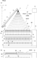
- FIG. 1 is a front view of the spun yarn take-up machine 1.
- FIG. 2(a) is a side view of the spun yarn take-up machine 1.
- FIG. 2(a) shows one (winding unit 5A) of a later-described pair of winding units 5.
- the spun yarn take-up machine 1 is configured to simultaneously form packages P by taking up plural (e.g., 32 in the present embodiment) yarns Y spun out from a spinning apparatus 2 and winding the yarns Y onto bobbins B.
- Each yarn Y is, for example, a multi-filament yarn having filaments (not illustrated).
- each yarn Y may be formed of a single filament.
- Each filament is a synthetic fiber made of, e.g., polyester.
- the spun yarn take-up machine 1 includes, for example, a first godet roller 3, a second godet roller 4, a pair of winding units 5 (winding units 5A and 5B), and a controller 6.
- the first godet roller 3 and the second godet roller 4 are arranged to take up yarns Y and feed them to the downstream side in a yarn running direction.
- the first godet roller 3 and the second godet roller 4 are supported by, for example, a supporting body 7.
- the supporting body 7 extends, for example, obliquely rearward and upward from a position above front end portions of the paired winding units 5.
- the first godet roller 3 is a roller having a rotational axis substantially in parallel to the left-right direction.
- the first godet roller 3 is, for example, attached to a front end portion of the supporting body 7.
- the first godet roller 3 is rotationally driven by an unillustrated motor.
- the yarns Y spun out from the spinning apparatus 2 are sent to the second godet roller 4 while being aligned in the left-right direction and wound onto the first godet roller 3.
- the second godet roller 4 is a roller having a rotational axis substantially in parallel to the left-right direction.
- the second godet roller 4 is, for example, provided above and rearward of the first godet roller 3.
- the second godet roller 4 is rotationally driven by an unillustrated motor.
- the second godet roller 4 is, for example, attached to the supporting body 7.
- the second godet roller 4 is, for example, arranged to be movable in the extending direction of the supporting body 7.
- the second godet roller 4 is movable between a roller front position indicated by two-dot chain lines shown in FIG. 2(a) and a roller rear position indicated by solid lines shown in FIG. 2(a) , by a roller movement mechanism 9, for example.
- the roller front position is a position forward of and below the roller rear position and is close to the first godet roller 3 as compared to the roller rear position.
- the roller front position is a position of the second godet roller 4 where yarn placement to the second godet roller 4 is performed.
- the roller rear position is a position of the second godet roller 4 where a later-described winding operation is performed.
- Each of the yarns Y is sent from the first godet roller 3 to the second godet roller 4, and then sent to one of the paired winding units 5.
- a half of the yarns Y is sent to the winding unit 5A and the remaining half of the yarns Y is sent to the winding unit 5B.
- a yarn path of each yarn Y running from the first godet roller 3 to the second godet roller 4 extends obliquely upward and rearward.
- a regulatory guide 8 is provided between the first godet roller 3 and the second godet roller 4, for example.
- the regulatory guide 8 is provided to hold the yarns Y to be aligned in the left-right direction and to arrange the intervals in the left-right direction of the yarns Y to be equal to predetermined intervals.
- Each of the paired winding units 5 is configured to form packages P by winding the yarns Y onto the bobbins B.
- the winding unit 5A and the winding unit 5B are provided below the first godet roller 3 and the second godet roller 4.
- the winding unit 5A and the winding unit 5B are provided to be substantially symmetric in the left-right direction (i.e., plane symmetric) (see FIG. 1 ).
- Each of the winding units 5 winds a half of the yarns Y (e.g., 16 yarns in the present embodiment) sent from the second godet roller 4.
- the winding unit 5A winds the left 16 yarns YA whereas the winding unit 5B winds the right 16 yarns YB.
- the controller 6 is, for example, a typical computer and is configured to control the entire spun yarn take-up machine 1.
- the controller 6 is electrically connected to sections of the spun yarn take-up machine 1.
- the controller 6 is electrically connected to an operation unit (not illustrated) operated by an operator.
- the operation unit has, for example, unillustrated operation buttons.
- the controller 6 is arranged to control the sections based on a predetermined program.
- the controller 6 is arranged to be able to control the sections in accordance with, for example, an operator's operation of the operation unit.
- each of the paired winding units 5 includes a supporting frame 11, a turret 12, and two bobbin holders 13. As described above, the winding unit 5A and the winding unit 5B are substantially symmetric in the left-right direction. Unless otherwise stated, the description of each constituent feature is applicable to both the winding unit 5A and the winding unit 5B.
- the supporting frame 11 is a member extending in the front-rear direction.
- the supporting frame 11 is cantilevered by a base 14 that stands vertically.
- the supporting frame 11 protrudes forward from the base 14 (see FIG. 2 ).
- the turret 12 is a disc-shaped member having a rotational axis substantially parallel to the front-rear direction.
- the turret 12 is rotatably supported by the base 14.
- the turret 12 is rotationally driven by a turret motor which is not illustrated.
- Each of the two bobbin holders 13 is rotatably supported by the turret 12 and protrudes forward from the front surface of the turret 12.
- the rotational axes of the two bobbin holders 13 are substantially in parallel to the front-rear direction.
- two bobbin holders 13 When viewed in the front-rear direction, two bobbin holders 13 are provided to be point symmetric about the center of the turret 12 (see FIG. 1 ). To each bobbin holder 13, the bobbins B provided for the respective yarns Y are attached to be lined up in the front-rear direction. The bobbins B are rotatably supported by each of the two bobbin holder 13. Each of the two bobbin holders 13 is independently rotated and driven by an unillustrated winding motor.
- each winding unit 5 includes the base 14 (see FIG. 1 ).
- the disclosure is not limited to this.
- two supporting frames 11 and two turrets 12 of the respective winding units 5A and 5B may be attached to the same base (not illustrated).
- Each winding unit 5 includes guide units 15, traverse guides 16, and a contact roller 17.
- a guide supporter 18 is provided to extend in the front-rear direction (see FIG. 2(a) and FIG. 2(b) ).
- the guide units 15 are attached to the guide supporter 18 to be movable along the front-rear direction.
- the guide units 15 are provided to correspond to the respective bobbins B and are aligned along the front-rear direction.
- Each of the guide units 15 includes a main body 19 and a fulcrum guide 20 (yarn guide of the present invention).
- the main body 19 is attached to the guide supporter 18 to be movable.
- the fulcrum guide 20 is fixed to the main body 19.
- Each of the fulcrum guides 20 is a fulcrum about which a corresponding yarn Y is traversed by each traverse guide 16.
- the guide units 15 are movable between winding positions (distanced positions; see FIG. 2(a) ) where the yarns Y are wound onto the bobbins B and gathered positions (see FIG. 2(b) ) where the guide units 15 are close to one another in the front-rear direction as compared to the distanced positions.
- the guide units 15 that are adjacent to one another in the front-rear direction are connected with one another by an unillustrated belt.
- the rearmost guide unit 15 is movable in the front-rear direction by, for example, an unillustrated linear slider.
- the guide units 15 are movable between the distanced positions and gathered positions where the units are gathered on the front side as compared to the distanced positions. Yarn threading (described later) to the fulcrum guides 20 is performed when the fulcrum guides 20 are at the gathered positions.
- the traverse guides 16 are aligned in the front-rear direction.
- Each of the traverse guides 16 is driven by, for example, an unillustrated traverse motor, and traverses the corresponding yarn Y in the front-rear direction.
- the contact roller 17 has a rotational axis that extends substantially in parallel to the front-rear direction.
- the contact roller 17 is provided immediately above the upper bobbin holder 13.
- the contact roller 17 is configured to make contact with the surfaces of the packages P supported by the upper bobbin holder 13. With this, the contact roller 17 applies a contact pressure to the surface of each package P to adjust the shape of each package P.
- each of the paired winding units 5 structured as described above when the upper bobbin holder 13 is rotationally driven, the yarns Y traversed by the traverse guides 16 are wound onto the bobbins B, with the result that the packages P are formed.
- the turret 12 is rotated to switch the upper and lower positions of the two bobbin holders 13.
- the bobbin holder 13 having been at the lower position is moved to the upper position, which allows the yarns Y to be wound onto the bobbins B attached to the bobbin holder 13 having been moved to the upper position, to form packages P.
- the bobbin holder 13 to which the fully-formed packages P are attached is moved to the lower position.
- the fully-formed packages P are then collected by, e.g., an unillustrated package collector.
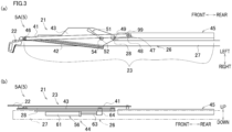
- FIG. 3(a) is a plan view of the yarn threading mechanism 21.
- FIG. 3(b) is a side view of the yarn threading mechanism 21.
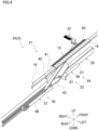
- FIG. 4 is a perspective view of the yarn threading mechanism 21 viewed from obliquely behind.
- FIG. 5 is a plan view of a later-described holding unit 22 and its surroundings.
- FIG. 6(a) illustrates a rear end portion of a later-described swing arm 43 and its surroundings.
- FIG. 6(b) is a schematic diagram showing the relationship between later-described air cylinders 56 and 57 and a path of compressed air. In FIG. 6(b) , both of the air cylinders 56 and 57 are shown in a single drawing.
- FIG. 7(a) and FIG. 7(b) shows a later-described yarn interval increaser 24.
- FIG. 7(a) is a side view of the yarn interval increaser 24.
- FIG. 7(b) shows the yarn interval increaser 24 viewed along an arrow VII(b) in FIG. 7(a) .
- each of the paired winding units 5 is provided with the yarn threading mechanism 21.
- the yarn threading mechanism 21 includes the holding unit 22 (see FIG. 3(a) to FIG. 5 ), a drive unit 23 (see FIG. 3(a) to FIG. 4 ), and the yarn interval increaser 24 (see FIG. 7(a) and FIG. 7(b) ).
- the yarn threading mechanism 21 is able to separate the yarns Y in the left-right direction by the yarn interval increaser 24 and to hold the separated yarns Y by the holding unit 22.
- the yarns Y are threaded to the respective fulcrum guides 20.
- the holding unit 22 and the drive unit 23 are provided in each winding unit 5. Between the winding unit 5A and the winding unit 5B, the holding units 22 and the drive units 23 are substantially symmetric in the left-right direction.
- the yarn interval increaser 24 is provided in the winding unit 5A and commonly used by the paired winding units 5. The following will describe only the yarn threading mechanism 21 provided in the winding unit 5A.
- the holding unit 22 is arranged to hold running yarns Y in a separated manner.
- the holding unit 22 of the winding unit 5A is arranged to be able to hold yarns YA (see FIG. 1 ).
- the holding unit 22 is attached to the winding unit 5A through the drive unit 23.
- a positionally-fixed supporting member 26 (see FIGs. 2 to 4 ) is provided between the supporting frame 11 and the guide supporter 18.
- the supporting member 26 includes, for example, as shown in FIG. 3(a) and FIG. 3(b) , a rod member 27 extending in the front-rear direction and a plate member 28 fixed to a front portion of the rod member 27.
- the holding unit 22 is attached to the supporting member 26 through the drive unit 23.
- the holding unit 22 includes, for example, a comb guide 31 and an interposed member 32 (see FIG. 5 ).
- the comb guide 31 is a plate member that is comb-shaped on the whole.
- the comb guide 31 includes a main body 33 and a connection part 34.
- the main body 33 has retaining grooves 35 in which the respective yarns Y are retained.
- the retaining grooves 35 are aligned at least in the left-right direction.
- the entrance of each retaining groove 35 is formed at a rear end portion of the main body 33, for example.
- the intervals of the entrances of the retaining grooves 35 in the direction in which the retaining grooves 35 are aligned are substantially identical with the intervals (predetermined intervals) in the left-right direction of the yarns Y, which are defined by the regulatory guide 8.
- a through hole 36 is formed at an intermediate portion of the main body 33 in the front-rear direction.
- the through hole 36 for example, penetrates the main body 33 in the up-down direction and extends in the left-right direction.
- a grip 37 holdable by the operator is formed at a front end portion of the main body 33, for example.
- the connection part 34 is a part connected to a left end portion of a rear end portion of the main body 33.
- connection part 34 is connected to the interposed member 32 through a shaft 38 that extends in the up-down direction.
- the position of the connecting portion 34 is fixed relative to the interposed member 32 by, for example, a fastener such as an unillustrated bolt. When the fastener is loosened, it may be possible for the comb guide 31 to swing about the axis 38 as the swing axis.
- the interposed member 32 is, for example, a roughly L-shaped member when viewed in the up-down direction.
- the interposed member 32 is fixed to a support arm 41 (described later) of the drive unit 23.
- the holding unit 22 can be adjusted in the front-rear direction by an operator under a predetermined condition. The details will be given later.
- the drive unit 23 is configured to move the holding unit 22.
- the drive unit 23 is attached to the supporting member 26.
- the drive unit 23 has a supporting arm 41, a guide rail 42, a swing arm 43, a swing driving source 44, and a front-rear driving mechanism 45 (a driving mechanism and an adjustment mechanism of the present invention) .
- the front-rear driving mechanism 45 is simply shown in a rectangular shape.
- the support arm 41 to which the holding unit 22 is attached is moved at least in the front-rear direction along the guide rail 42 on account of the operation of the front-rear driving mechanism 45.
- the guide rail 42 is able to change the direction of movement of the support arm 41 and the holding unit 22 by being swung together with the swing arm 43 by the swing driving source 44.
- the teeth 82a are configured to mesh with the teeth 81a of the rack 81.
- the pinion 82 is provided on the downstream side of the piston rod 68 and on the upstream side of the transmission mechanism 83 in the direction of transmission of the thrust force of the air cylinder 57.
- the direction of transmission of the thrust force of the air cylinder 57 is simply referred to as a transmission direction.
- the side close to the piston 67 is defined as the upstream side
- the side far from the piston 67 is defined as the downstream side.
- the transmission mechanism 83 is configured to transmit the thrust force of the air cylinder 57 to the holding unit 22. Furthermore, the transmission mechanism 83 is configured to transmit the force applied by the operator to the holding unit 22 to the piston rod 68 when the holding unit 22 is moved by the operator.
- the transmission mechanism 83 is provided downstream of the pinion 82 and upstream of the holding unit 22 in the transmission direction.
- the transmission mechanism 83 has a base member 91, a guide rail 92, a sliding member 93, a first pulley 94, a second pulley 95, a third pulley 96, a fourth pulley 97, an endless belt 98, and the aforementioned movable body 99.
- the first pulley 94 to the fourth pulley 97 are rotatably supported by the base member 91 that is movable together with the piston rod 68.
- the endless belt 98 is wound onto the first pulley 94 to the third pulley 96.
- the endless belt 98 is bent by the fourth pulley 97.
- the movable body 99 is fixed to the endless belt 98 and is connected to the holding unit 22.
- the long section 91a is a portion that extends from the front end to the rear end of the base member 91, for example.
- the long section 91a is positioned above the air cylinder 57, for example.
- the short section 91b is a part that extends downward from a rear end portion of the long section 91a, for example.
- the short section 91b is fixed to, for example, the rod end 69. This allows the base member 91 to move in the front-rear direction together with the piston rod 68.
- the base member 91 is capable of moving in the front-rear direction along the guide rail 92, together with the sliding member 93.
- the base member 91 supports the first pulley 94 to the fourth pulley 97 to be rotatable.
- Each of the first pulley 94 to the fourth pulley 97 is rotatably supported by the base member 91.
- the position of each of the first pulley 94 to the fourth pulley 97 is fixed relative to the base member 91.
- the rotational axis direction of each of the first pulley 94 to the fourth pulley 97 is, for example, substantially in parallel to the left-right direction.
- the first pulley 94 to the fourth pulley 97 for example, are arranged on the opposite side of the rack 81 and the pinion 82 over the base member 91 in the left-right direction.
- the first pulley 94 (a first rotated member of the present invention) is a pulley around which an endless belt 98 is wound.
- the first pulley 94 is, for example, rotatably supported at the front end portion of the long section 91a of the base member 91.
- the first pulley 94 is positioned above the air cylinder 57, for example.
- the third pulley 96 (the third rotated member of the present invention) is similar to the first pulley 94 and the second pulley 95, and is a roller on which the endless belt 98 is wound.
- the third pulley 96 is rotatable together with the pinion 82. More specifically, the third pulley 96 is configured to be coaxial with the pinion 82.
- the third pulley 96 is positioned upstream of the first pulley 94 and the second pulley 95 in the transmission direction.
- the pitch circle diameter of the third pulley 96 is substantially equal to the pitch circle diameter of the pinion 82.
- the third pulley 96 is rotatably supported by the short section 91b of the base member 91, for example.
- the third pulley 96 is, for example, provided directly below the second pulley 95.
- the third pulley 96 is arranged at substantially the same position as the second pulley 95 in the front-rear direction, for example.
- the rotation axis center of the third pulley 96 is positioned at a different location from the rotation axis centers of the first pulley 94 and the second pulley 95 in the up-down direction, for example.
- the third pulley 96 is positioned directly behind the rod end 69 of the air cylinder 57, for example.
- the endless belt 98 (a wound member of the present invention) is, for example, a known toothed belt.
- the endless belt 98 is wound around, for example, the first pulley 94 to the third pulley 96 (more specifically, for example, the belt is parallelly wound).
- the inner circumferential surface of the endless belt 98 is in contact with the first pulley 94 to the third pulley 96.
- a portion of the endless belt 98, which is provided between the first pulley 94 and the second pulley 95 in the front-rear direction and extends substantially linearly, is referred to as an extending portion 98e (see FIG. 9(a), FIG. 9(b) ) for the convenience of explanation.
- the endless belt 98 is arranged to overlap at least partially with the air cylinder 57 in the left-right direction. More specifically, for example, the entire region in the longitudinal direction of the endless belt 98 is arranged to extend, for example, on a virtual plane VPB that is orthogonal to the left-right direction and is different from the virtual plane VPA.
- the outer circumferential surface of the endless belt 98 is in contact with the fourth pulley 97.
- the endless belt 98 is bent by the fourth pulley 97 so as not to interfere with the air cylinder 57.
- the movable body 99 is a member fixed to the extending portion 98e of the endless belt 98.
- the movable body 99 is configured, for example, to sandwich the endless belt 98 in the thickness direction of the endless belt 98.
- the movable body 99 is fixed to the endless belt 98 by, for example, a fastener such as an unillustrated bolt.
- the movable body 99 may be fixed to the endless belt 98 by, for example, adhesion.
- the movable body 99 is capable of moving in the front-rear direction together with the extending portion 98e of the endless belt 98 when the endless belt 98 moves relative to the first pulley 94 to the fourth pulley 97.
- the movable body 99 moves relative to the rack 81 as the base member 91 moves in a parallel manner in the front-rear direction, and also moves relative to the first pulley 94 to the fourth pulley 97.
- the movable body 99 is connected to the holding unit 22, for example, via the above-described supporting arm 41 (see FIG. 3(a) ). This allows the holding unit 22 to be movable at least in the front-rear direction in accordance with the movement of movable body 99 in the front-rear direction.
- the state of the air cylinder 57 is in the above-described non-actuated state.
- a predetermined force F1 (see FIG. 9(b) ) that is substantially identical with the rearward force in magnitude is applied to the movable body 99 and the endless belt 98.
- the first pulley 94 to the fourth pulley 97 rotate as the endless belt moves.
- a force that is substantially identical with the force F1 in magnitude is applied to the first pulley 94 to the fourth pulley 97.
- the pinion 82 rotates together with the third pulley 96.
- the pitch circle diameter of the pinion 82 is substantially equal to the pitch circle diameter of the third pulley 96.
- a force that is substantially identical with the force F1 in magnitude (but opposite in direction to the force F1 in the front-rear direction) is applied to the teeth 82a of the pinion 82. Because the teeth 82a of the pinion 82 mesh with the teeth 81a of the rack 81, the pinion 82 receives a reaction force (force F2) from the rack 81 that is a force rotating and moving the pinion 82 rearward.
- the force F1 is substantially identical with the force F2 in magnitude.
- a resultant force of the forces F1 and F2 i.e., a force twice as much as the force F1 in magnitude and acting rearward acts on the piston rod 68 of the air cylinder 57.
- This resistance force mainly includes a friction force acting between the cylinder main body 66 and the piston 67 (see FIG. 6(b) ).
- the operator can move the holding unit 22 only by applying a force that is smaller than the force F3 (specifically, a force that is half as much as the force F3) to the holding unit 22.
- the moving distance in the front-rear direction of the movable body 99 is referred to as a first distance D1 (see FIG. 9(b) ).
- the moving distance of the piston rod 68 (and the pinion 82) in the same direction as the movable body 99 in the front-rear direction when the movable body 99 moves in the front-rear direction by the first distance D1 is referred to as a second distance D2 (see FIG. 9(b) ) for the sake of explanation.
- the second distance D2 is shorter than the first distance D1.
- the second distance D2 is half as long as the first distance D1.
- the pinion 82 is equivalent to the movable pulley.
- the resistance force is equivalent to the gravity acting on a weight hanging down from the movable pulley.
- the rack 81 is equivalent to a string supported by the ceiling.
- the force with which the rotating pinion 82 is supported (pushed back) by the rack 81 is equivalent to a force with which the ceiling supports the movable pulley.
- the force applied to the holding unit 22 (and the movable body 99) in the front-rear direction is equivalent to a force with which a hand of the operator pulls the string.
- the first distance D1 is equivalent to the distance at which a hand of the operator pulls the string.
- the second distance D2 is equivalent to the moving distance of the movable pulley. Based on the principle, while the first distance D1 is increased, the force required to be applied to the holding unit 22 is decreased. In this way, the operability of the holding unit 22 can be improved.
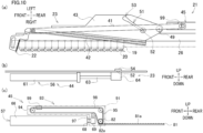
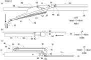
- FIGs. 10(a) to 10(c) illustrate a state in which the holding unit 22 is at a holding unit retracted position.
- FIGs. 11(a) to 11(f) illustrate operations until the yarns Y are pressed onto the separation roller 74 in yarn threading to the spun yarn take-up machine 1.
- FIGs. 12 (a) to 12(c) illustrate movement of the holding unit 22 to a capture preparation position (described later).
- FIGs. 13(a) to 13(c) illustrate fine adjustment of the position of the holding unit 22.
- FIG. 13(b) is an enlarged view of a region R shown in FIG. 13(a) .
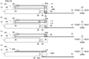
- FIGs. 14(a) and 14(b) are explanatory diagrams illustrating forces acting on sections of the front-rear driving mechanism 45. More specifically, FIG. 14 (a) shows the forces applied to sections of the front-rear driving mechanism 45 during manual operation of the holding unit 22 by the operator.
- FIG. 14 (b) is a diagram illustrating forces acting on sections of the front-rear driving mechanism 45 operated by compressed air.
- the left side of the sheet corresponds to the front side of the present embodiment
- the right side of the sheet corresponds to the rear side of the present embodiment.
- FIGs. 15(a) to 15(c) illustrate the retraction of the holding unit 22.
- FIGs. 16(a) to 16(c) illustrate the movement of the holding unit 22 to the yarn threading start position.
- FIGs. 17(a) to 17(c) are explanatory diagrams illustrating the movement of the holding unit 22 to the yarn threading completion position.
- FIG. 18 illustrates how the yarns Y are threaded to the fulcrum guides 20, respectively.
- the position of the rod end 64 and the pin 52 in the front-rear direction when the piston rod 63 of the air cylinder 56 is fully extended is referred to as an "extended position”.
- the position of the rod end 64 and the pin 52 in the front-rear direction when the piston rod 63 is fully contracted is called a "contracted position”.
- the position of the movable body 99 in the front-rear direction when the piston rod 68 of the air cylinder 57 is fully extended is referred to as a "rear end position”.
- the position of the movable body 99 in the front-rear direction when the piston rod 68 is fully contracted is referred to as a "front end position”.
- the operator threads the yarns Y to the first godet roller 3, the regulatory guide 8, and the second godet roller 4. Then the operator temporarily presses the yarns Y onto the separation roller 74. Furthermore, the operator causes the holding unit 22 to hold the yarns Y. Finally, the yarn threading mechanism 21 is driven under the control of the controller 6 to move the holding unit 22 from the aforementioned capturing position to the yarn threading start position, and further move the unit to the yarn threading completion position. As a result, the multiple yarns Y held by the holding unit 22 are threaded to the respective fulcrum guides 20.
- the piston rod 63 of the air cylinder 56 is at the extended position (see FIG. 10 (b) ).
- the movable body 99 is located at the above-described front end position (see FIG. 10(c) ).
- Each of the paired holding units 22 is therefore at the predetermined holding unit retracted position (see FIG. 3(a) and FIG. 10 (a) ).
- the separation roller 74 is at the roller retracted position (indicated by two-dot chain lines in FIG. 7(a) ).
- the operator performs a predetermined input operation to the input unit (not illustrated) of the controller 6.
- the controller 6 controls the sections of the spun yarn take-up machine 1 so that the state of the spun yarn take-up machine 1 is in a yarn threading preparation state described below. That is to say, the controller 6 moves the second godet roller 4 to the front position (see FIG. 11(a) ). Furthermore, the controller 6 moves the fulcrum guides 20 to the gathered positions (see e.g., FIG. 10(a) ).
- the operator operates the grip 73 of the yarn interval increaser 24 to rotate the rotation arm 72, so as to move the separation roller 74 from the roller retracted position to the roller contact position (see full lines in FIG. 7(a) and FIG. 11(a) ).
- the operator then sucks and holds the yarns Y (to be more specific, all of 32 yarns YA and YB) by using a suction gun SG (see FIG. 11(a) ) arranged to be able to suck and hold the yarns Y.
- a suction gun SG By operating the suction gun SG, the operator threads the yarns Y to the first godet roller 3, the regulatory guide 8, and the second godet roller 4 in this order (see FIG. 11(a) ).
- the operator operates the suction gun SG to move the leading end portion of the suction gun SG to a position below and to the right of the separation roller 74 (see FIGs. 11(b) and 11(c) ).
- the operator moves the yarns Y to a position immediately behind the separation roller 74 (see FIG. 11(d) ).
- the intervals of the yarns Y running from the regulatory guide 8 toward the suction gun SG narrow toward the suction gun SG.
- the operator moves the leading end portion of the suction gun SG forward to cause the yarns Y to make contact with the circumferential surface of the separation roller 74 (see FIG. 11(e) and FIG. 11(f) ).
- the separation roller 74 is passively rotated by the friction force between the roller and the running yarns Y.
- the intervals in the left-right direction of the yarns Y in contact with the separation roller 74 are widened to be substantially as wide as the intervals in the left-right direction of the yarns Y regulated by the regulatory guide 8 (see FIG. 11(f) ).
- yarn paths that are aligned in the left-right direction and are substantially in parallel to one another are formed.
- the operator makes an input for starting the operation of the yarn threading mechanism 21 to the input unit of the controller 6.
- the controller 6 controls the sections of the yarn threading mechanism 21. The following will describe only the operation of the yarn threading mechanism 21 in the winding unit 5A.
- the controller 6 controls the operation of the air cylinder 56 to move the piston rod 63 of the air cylinder 56 from the extended position (see FIG. 10(b) ) to the contracted position (see FIG. 12(b) ).
- the pin 52 moves forward as a result, the swing arm 43 and the guide rail 42 are passively swung as the guide hole 51 of the swing arm 43 follows the pin 52 (see FIG. 12 (a) ). Due to this, the front end portion of the support arm 41 and the holding unit 22 follow the guide rail 42 and are swung rightward (see FIG. 12(a) ).
- the holding unit 22 moves from the holding unit retracted position to the vicinity of a capturing position (described later) where the yarns YA can be captured.
- the holding unit 22 moves from the holding unit retracted position to the capture preparation position (see FIG. 12(a) ) where the operator causes the holding unit 22 to capture the yarns YA.
- the capture preparation position is a position that is at least forward of the capturing position.
- the capture preparation position of the holding unit 22 is immediately above a left portion of the separation roller 74 and immediately in front of the yarns YA.
- the controller 6 temporarily stops the operation of the yarn threading mechanism 21.
- the controller 6 controls the electromagnetic valve EV2 (see FIG. 6(b) ) to discharge compressed air from both the piston chamber 66F and the piston chamber 66R of the air cylinder 57.
- the swing arm 43 is provided with a guide hole 51.
- the width of the guide hole 51 is very slightly larger than the outer diameter of the pin 52, except at the front end portion.
- the front end portion of the guide hole 51 has a play 53.
- the pin 52 is inserted into the front end portion of the guide hole 51 (i.e., when the piston rod 63 is at the contracted position)
- the pin 52 is loosely fitted with the play 53. Therefore, the operator can manually swing the swing arm 43 in the left-right direction by a hand (see FIGs. 13(a) and 13(b) ).
- the operator can move the holding unit 22 (and the movable body 99) in the front-rear direction when the air cylinder 57 is in a non-actuated state.
- the operator moves the comb guide 31 by holding the grip 37 by a hand.
- the holding unit 22 can be moved rearward.
- the operator manually moves the holding unit 22 from the capture preparation position to the capturing position, and causes the holding unit 22 to capture the yarns YA (see FIG. 13(c) ).
- the holding unit 22 holds the yarns YA to be separated from one another in the left-right direction, for example.
- the operator After causing the holding unit 22 to capture the yarns YA, the operator makes an input to the input unit of the controller 6 to continue the yarn threading.
- the controller 6 continues the yarn threading in accordance with the input signal.
- the controller 6 controls the air cylinder 57 to move the movable body 99 from the front end position to the rear end position.
- the controller 6 puts the air cylinder 57 in the actuated state.
- the controller 6 controls the solenoid valve EV2 to supply compressed air to the piston chamber 66F.
- the piston 67 is pushed rearward by the compressed air in the piston chamber 66F, and a predetermined force is applied to the piston 67 and the piston rod 68 (see a force F6 described in FIG. 14 (b) for details).
- the magnitude of the force F6 is required to be at least twice greater than the magnitude of the force F4.
- the controller 6 may return the second godet roller 4 to the roller rear position before controlling the solenoid valve EV2 as described above. Alternatively, the controller 6 may move the second godet roller 4 to the roller rear position after the yarn threading to the fulcrum guides 20 is completed.
- the controller 6 controls the air cylinder 56 to move the piston rod 63 from the contracted position to the extended position (see FIG. 16(b) ). Consequently, the pin 52 is moved rearward, and this causes the swing arm 43 to swing leftward. Due to this, the inclination angle of the guide rail 42 is changed relative to the front-rear direction, and the inclination angle of the holding unit 22 is also changed (see FIG. 16(a) ).
- the guide rail 42 extends obliquely forward and leftward from a position in the vicinity of the fulcrum guide 20 that is the rearmost fulcrum guide of the winding unit 5A, toward a position in the vicinity of the frontmost fulcrum guide 20.
- the holding unit 22 is at the yarn threading start position of the present invention.
- the yarn threading start position is rearward of the capturing position.
- the controller 6 controls the air cylinder 57 to move the movable body 99 from the rear end position to the front end position (see FIG. 17(c) ).
- the front end portion of the support arm 41 is moved forward along the cylinder main body 66, and the front end portion of the support arm 41 is moved obliquely forward and leftward along the guide rail 42 (see FIG. 17 (a) and FIG. 18 ) .
- the yarns YA retained in the respective retaining grooves 35 of the holding unit 22 are threaded to the corresponding fulcrum guides 20, respectively (see FIG. 18 ).
- the holding unit 22 moves to the yarn threading completion position that is at least forward of the yarn threading start position (see the full lines in FIG.
- the yarn threading to the fulcrum guides 20 of the winding unit 5B is similarly done.
- controller 6 controls the sections of the paired winding units 5 to perform, for example, the yarn threading to the bobbins B. (Details are omitted.) As a result, it becomes possible to start winding of the yarns Y onto the respective bobbins B.
- the front-rear driving mechanism 45 (adjustment mechanism) of the present embodiment utilizes the principle of movable pulley. Based on the principle, while the first distance D1 is increased, the force required to be applied to the holding unit 22 is decreased. As a result, the holding unit 22 provided in the yarn threading mechanism 21 can be positionally adjusted with a small force.
- the yarn threading mechanism 21 is configured to allow manual adjustment of the position in the front-rear direction of the holding unit 22 between the capture preparation position and the capturing position when the state of the air cylinder 57 is in the non-actuated state.
- the yarn threading mechanism 21 is configured to move the holding unit 22 from the capturing position to the yarn threading start position, and further move the same to the yarn threading completion position, thereby enabling the yarns Y held by the holding unit 22 to be threaded to the fulcrum guides 20.
- the air cylinder 57 becomes in the non-actuated state as a result of the discharge of compressed air from both the piston chamber 66F and the piston chamber 66R. That is to say, for example, it is possible to form a front-rear driving mechanism 45 (drive mechanism) by utilizing an air cylinder which is typically inexpensive as compared to a fluid pressure cylinder such as a motor-driven cylinder and a hydraulic cylinder. Therefore, it is possible to reduce the component cost of the spun yarn take-up machine 1.
- first pulley 94 and the second pulley 95 are rotatably supported by the base member 91.
- the endless belt 98 is wound onto the first pulley 94 and the second pulley 95.
- the first pulley 94, the second pulley 95, the endless belt 98, and the movable body 99 can be arranged so that they fit within an area that is approximately the same size as a range in which the base member 91 extends in the front-rear direction.
- the moving distance in the front-rear direction of the base member 91 is equal to the moving distance (extension-and-contraction distance) in the front-rear direction of the piston rod 68. This suppresses the traveling range of the transmission mechanism 83 to be short in the front-rear direction. Therefore, increase in size of the spun yarn take-up machine 1 in the front-rear direction can be avoided.
- the rotation axis center of the third pulley 96 is positioned at a different location from the rotation axis centers of the first pulley 94 and the second pulley 95 in the up-down direction. Therefore, the position in the up-down direction of the third pulley 96 can be set freely to some degree. Therefore, the positions in the up-down direction of the pinion 82 and the rack 81 can be set freely to some degree. On this account, it is possible to easily avoid an interference between the transmission mechanism 83 and the rack 81.
- the pitch circle diameter of the third pulley 96 is substantially equal to the pitch circle diameter of the pinion 82. This makes it easy to achieve both the reduction of the force required to manually move the holding unit 22 and the suppression of increase in force required to move the holding unit 22 by the air cylinder 57.
- the third pulley 96 is arranged at substantially the same position as the second pulley 95 in the front-rear direction. Therefore, it is possible to avoid the transmission mechanism 83 from being upsized in the front-rear direction due to the third pulley 96.
- the transmission mechanism 83 includes the fourth pulley 97.
- the endless belt 98 By arranging the endless belt 98 to overlap at least partially with the air cylinder 57 in the left-right direction, it is possible to suppress the enlargement of the spun yarn take-up machine 1 in the left-right direction.
- the endless belt 98 may interfere with the air cylinder 57.
- the shape of the endless belt 98 can be freely set to some extent by the fourth pulley 97. This suppresses the enlargement of the spun yarn take-up machine 1 in the left-right direction and enables easy avoidance of interference between the air cylinder 57 and the endless belt 98.
- the fourth pulley 97 is positioned between the first pulley 94 and the second pulley 95 in the front-rear direction.
- the fourth pulley 97 is provided between (i) the first pulley 94 and the second pulley 95 and (ii) the third pulley 96 in the up-down direction. Therefore, it is possible to avoid the transmission mechanism 83 from being upsized in the front-rear direction and/or the up-down direction due to the fourth pulley 97.
- the guide rail 92 is disposed to overlap at least partially with the rack 81 in the left-right direction. Therefore, it is possible to suppress the yarn threading mechanism 21 from being upsized in the left-right direction by the guide rail 92.
- the yarn threading mechanism 21 includes the rack 81 and the pinion 82.
- a typical rack-and-pinion mechanism with a simple structure is used in the yarn threading mechanism 21. Therefore, it is possible to suppress the structural complication of the yarn threading mechanism 21.
- a transmission mechanism 103 may be provided.
- an endless belt 98A may be wound onto the first pulley 94 and the second pulley 95.
- the pinion 82 may be provided on the same axis as the second pulley 95, and the rack 81 may be provided in accordance with the position of the pinion 82.
- the rack 81 may be required to be positionally different from the guide rail 92 in the left-right direction.
- the transmission mechanism 83, etc. includes the first pulley 94 and the second pulley 95.
- a transmission mechanism 104 may be provided.
- the transmission mechanism 104 may not include the first pulley 94 and the second pulley 95.
- the transmission mechanism 104 may include, for example, a rack 81, a pinion 82M, and a rack 113.
- the pitch circle diameter of the pinion 82M may be different from the pitch circle diameter of the pinion 82.
- the pinion 82M may be rotatably attached to a rod end 69A.
- the rack 113 may be provided to be opposite to the rack 81 over the pinion 82M in the up-down direction and extend in the front-rear direction, for example.
- a movable body 99A may be provided in place of the movable body 99.
- the movable body 99A may be fixed to a front end portion of the rack 113. In this arrangement, however, the relative positions of the rear end of the rack 113 and the movable body 99A remain the same in the front-rear direction. On this account, after the movable body 99A is moved to the rear end position, the rear end portion of the rack 113 may protrude rearward as compared to the rack 81. Therefore, in this modification, the installation area of the spun yarn take-up machine 1 needs to be long in the front-rear direction.
- the front-rear driving mechanism 45 includes the air cylinder 57.
- the disclosure is not limited to this.
- a known magnet-type rodless cylinder may be provided, for example.
- a fluid pressure cylinder (e.g., a hydraulic cylinder) driven by fluid different from compressed air may be provided. Also in this case, the state of the fluid pressure cylinder becomes the non-actuated state as the fluid is discharged from piston chambers (not illustrated) provided on the both sides in the front-rear direction of the cylinder main body (not illustrated) of the fluid pressure cylinder.
- an electric driving source such as a known stepping motor may be provided.
- the holding unit 22 can be manually moved.
- a stator (not illustrated) of the motor is equivalent to the fixed portion of the present invention.
- a rotor and a rotation shaft (not illustrated) of the motor are equivalent to the movable portion of the present invention.
- the installation location of the motor may not be fixed.
- the rotational shaft of the motor may be connected to the pinion 82.
- the motor may be movable with the pinion 82 in a parallel manner relative to the rack 81.
- the transmission mechanism 83, etc. includes the pulleys and the endless belt 98.
- the disclosure is not limited to this.
- known sprockets may be provided as the first to fourth rotated members of the present invention.
- a known chain (not illustrated) may be provided in place of the endless belt 98.
- the yarn threading mechanism 21 moves the holding unit 22 from the capturing position to the yarn threading start position by the drive unit 23 and further moves the holding unit 22 to the yarn threading completion position.
- the disclosure is not limited to this.
- the yarn threading mechanism 21 may be arranged so that the series of movement steps is partially performed by the operator.
- the play 53 formed at the front end portion of the guide hole 51 contributes to the position adjustment of the holding unit 22.
- the disclosure is not limited to this.
- the comb guide 31 may be swingable relative to the above-described interposed member 32.
- the comb guide 31 may be connected to the support arm 41 through an unillustrated spring (e.g., a compression coil spring, a tension coil spring, and/or a torsion coil spring).
- the air cylinder 56 is arranged to swing the guide rail 42.
- the disclosure is not limited to this.
- a mechanism configured to horizontally move the guide rail 42 may be provided.
- the guide rail 42 is linear in shape and the position of the guide rail 42 is changed according to an object.
- a guide rail (not illustrated) that does not need to be moved may be provided to extend along the track of movement of the paired holding unit 22.
- the fulcrum guides 20 are movable between the distanced positions and the gathered positions.
- the fulcrum guides 20 may be immovable. In this case, however, the drive unit 23 may be upsized in the front-rear direction.
- the holding unit 22 is moved from the holding unit retracted position to the capturing position.
- the disclosure is not limited to this. As long as the holding unit 22 is not obstructive, the holding unit 22 may be provided at the capture preparation position from the beginning.
- the yarn threading mechanism 21 includes the yarn interval increaser 24.
- the yarn threading mechanism 21 may not include the yarn interval increaser 24.
- An arrangement by which the compressed air is discharged from both of the piston chambers 66F and 66R is not limited to the arrangement shown in FIG. 6(b) .
- two three-way electromagnetic valves (not illustrated) may be provided in place of the electromagnetic valve EV2, and a path for supplying and discharging compressed air may be suitably provided to discharge the compressed air from both of the piston chambers 66F and 66R.
- the cylinder main body 66 of the air cylinder 57 is fixed to the supporting member 26.
- a swing shaft (not illustrated) may be provided at a rear end portion of the cylinder main body 66 to extend in the up-down direction, and the cylinder main body 66 may be swingable about the swing shaft.
- the guide rail 42 and the cylinder main body 66 swing together.
- the support arm 41 may be fixed to the movable body 99.
- the yarn threading mechanism 21 is arranged to thread the yarns Y to the fulcrum guides 20.
- the disclosure is not limited to this.
- a yarn threading mechanism may be provided to thread yarns Y to these yarn guides.
- spun yarn take-up machine 1 includes the paired winding units 5 (winding units 5A and 5B), the disclosure is not limited to this arrangement.
- the spun yarn take-up machine 1 may include, for example, only the winding unit 5A among the winding units 5A and 5B.
- the front-rear direction is equivalent to the first direction of the present invention
- the up-down direction is equivalent to the second direction of the present invention
- the left-right direction is equivalent to the third direction of the present invention.
- the first direction may be tilted relative to the front-rear direction.
- the second direction may be tilted relative to the up-down direction.
- the third direction may be tilted relative to the left-right direction.
- the present invention can be applied to various yarn winders each of which is configured to wind yarns Y.
Landscapes
- Engineering & Computer Science (AREA)
- Textile Engineering (AREA)
- Replacing, Conveying, And Pick-Finding For Filamentary Materials (AREA)
- Guides For Winding Or Rewinding, Or Guides For Filamentary Materials (AREA)
- Yarns And Mechanical Finishing Of Yarns Or Ropes (AREA)
- Spinning Or Twisting Of Yarns (AREA)
Abstract
Description
- The present invention relates to a yarn winder.
- Patent Literature 1 (
Japanese Laid-Open Patent Publication No. 2017-114573 - The inventors of the subject application are trying to improve yarn threading mechanisms in order to simplify the above-described yarn threading and to shorten the time required for the yarn threading. To be more specific, firstly, a driving mechanism by which a holding unit holding yarns is moved without human power has been developed. Secondly, an adjustment mechanism that allows an operator to manually adjust the position of a holding unit when yarns are held by the holding unit has been developed.
- In addition to the above, an arrangement that allows an operator to manually move the holding unit when the driving mechanism is not driven has been planned. In such an arrangement, at least part of the driving mechanism functions as the adjustment mechanism. In this connection, improvement in operability of the holding unit has been at issue.
- An object of the present invention is to achieve positional adjustment of a holding unit of a yarn threading mechanism with a small power.
- According to a first aspect of the invention, a yarn winder which is configured to wind running yarns onto bobbins aligned in a predetermined arrangement direction comprises: yarn guides which are provided to correspond to the respective bobbins and are aligned in the arrangement direction; and a yarn threading mechanism which is configured to perform yarn threading to the yarn guides, the yarn threading mechanism including: a holding unit which is capable of holding, in a separated manner, the yarns before being wound onto the yarn guides; and a driving mechanism which includes a driving source and is configured to be able to move the holding unit in a first direction having a component in the arrangement direction, the driving source including a fixed portion and a movable portion movable relative to the fixed portion and being switchable between an actuated state in which a thrust force is applied in the first direction to the holding unit through the movable portion and a non-actuated state in which application of the thrust force to the holding unit is canceled, the driving mechanism including: an extending member which is fixed in installation location and extends in the first direction; a rotation member which is rotatably supported by the movable portion and is arranged to be movable in the first direction relative to the extending member in such a way that the rotation member rolls by making contact with the extending member; and a transmission mechanism which includes a movable body arranged to be movable together with the holding unit and movable in the first direction, and which is provided between the rotation member and the holding unit in a direction of transmission of the thrust force, and when the movable body is moved in the first direction from a predetermined position by a predetermined first distance, the transmission mechanism moving the rotation member in the first direction by a second distance that is shorter than the first distance toward a side identical with a side toward which the movable body moves, by rotating the rotation member in accordance with the movement of the movable body.
- According to this aspect of the present invention, by putting the driving source of the driving mechanism in the non-actuated state, it becomes possible to manually move the movable portion connected to the holding unit. More specifically, when the driving source is in the non-actuated state, if the operator applies a force to the holding unit (and the movable body), the rotation member supported by the movable portion can rotate through the transmission mechanism and move in the first direction along the extending member. In other words, manual movement in the first direction of the holding unit is allowed. Here, in order to move the movable portion, it is necessary to apply a force to the movable portion which is greater than the resistance force (e.g., friction force) acting between the movable portion and the fixed portion. For example, in a configuration where the holding unit and the movable portion are integrally movable, it is necessary to apply a force to the holding unit which is greater than the resistance force described above.
- In this regard, the driving mechanism of the present invention is a mechanism that applies the known principle of movable pulley, as described below. The rotation member is equivalent to the movable pulley. The resistance force is equivalent to the gravity acting on a weight hanging down from the movable pulley. The extending member is equivalent to a string supported by the ceiling and wound onto the movable pulley. The force with which the rotating rotation member is supported by the extending member is equivalent to a force with which the ceiling supports the movable pulley. The force applied to the holding unit and the movable body in the first direction is equivalent to a force with which a hand of the operator pulls the string. The first distance is equivalent to the distance at which a hand of the operator pulls the string. The second distance is equivalent to the moving distance of the movable pulley. Based on the principle, while the first distance is increased, the force required to be applied to the holding unit is decreased. (Details will be given in the embodiment below.) As a result, the holding unit provided in the yarn threading mechanism can be positionally adjusted with a small force.
- According to a second aspect of the invention, the yarn winder of the first aspect is arranged such that, when the driving source is in the non-actuated state, the yarn threading mechanism is arranged so that the position of the holding unit in the first direction is manually adjustable between a predetermined capture preparation position and a capturing position which is on one side in the first direction of the capture preparation position and where capture of the yarns is possible, and when the driving source is in the actuated state, the yarn threading mechanism being capable of threading the yarns held by the holding unit to the respective yarn guides by moving the holding unit from the capturing position to a yarn threading start position that is on the one side of the capturing position in the first direction and further moving the holding unit to a yarn threading completion position that is on the other side of the yarn threading start position in the first direction.
- According to this aspect of the present invention, when moving the holding unit from the capture preparation position to the capturing position, it is possible to manually adjust the position of the holding unit in a delicate manner, as the driving source is switched to the non-actuated state. Furthermore, by putting the driving source in the actuated state, it is possible to perform yarn threading without manual intervention, by using the yarn threading mechanism. Therefore, the time and labor required for yarn threading can be reduced.
- According to a third aspect of the invention, the yarn winder of the second aspect is arranged such that the driving source includes an air cylinder configured to move the movable portion relative to the fixed portion by using pressure of compressed air, the air cylinder includes a cylinder main body that is the fixed portion and a piston that is the movable portion, the cylinder main body includes a first piston chamber and a second piston chamber that is provided to be opposite to the first piston chamber over the piston, and as the compressed air is discharged from both of the first piston chamber and the second piston chamber, the air cylinder is switched to the non-actuated state.
- According to this aspect of the present invention, it is possible to form the driving mechanism and the adjustment mechanism by utilizing an air cylinder which is typically inexpensive as compared to, for example, a motor-driven cylinder and a hydraulic cylinder. Therefore, it is possible to reduce the component cost of the yarn winder.
- According to a fourth aspect of the invention, the yarn winder of any one of the first to third aspects is arranged such that the transmission mechanism includes: a base member which is movable together with the movable portion; a first rotated member which is provided on the downstream side of the rotation member in the transmission direction and which is rotatably supported by the base member; a second rotated member which is provided to be side by side with the first rotated member in the first direction and which is rotatably supported by the base member; and a wound member which has an extending portion extending in the first direction, the movable body being fixed to the extending portion, and the wound member being allowed to be wound onto the first rotated member and the second rotated member.
- The adjustment mechanism may have, for example, a pinion provided as a rotation member, a first rack provided as an extending member, and a second rack that is provided as a part of the transmission mechanism, extends in the first direction, and is movable integrally with the holding unit. However, with this configuration, the moving distance of the second rack in the first direction is long, and hence there is a risk that the leading end of the second rack may unintentionally protrude as compared to the leading end of the first rack in the first direction. Therefore, it may be necessary to secure a wide area in which the second rack can move in the first direction, which may result in upsizing of the yarn winder.
- In the present invention, the first rotated member and the second rotated member are rotatably supported by the base member. Furthermore, the wound member is wound around the first rotated member and the second rotated member. In this configuration, the first rotated member, the second rotated member, the wound member, and the movable body can be arranged so that they fit within an area that is approximately the same size as a range in which the base member extends in the first direction. Furthermore, the moving distance in the first direction of the base member is equal to the moving distance in the first direction of the movable portion. This suppresses the traveling range of the transmission mechanism to be short in the first direction. Therefore, increase in size of the yarn winder can be suppressed in the first direction.
- According to a fifth aspect of the invention, the yarn winder of the fourth aspect is arranged such that the transmission mechanism includes a third rotated member which is provided to be rotatable together with the rotation member and is provided on the upstream side of the first rotated member and the second rotated member in the transmission direction, and in a predetermined second direction orthogonal to both the first direction and a rotational axis direction of the third rotated member, the rotation axis center of the third rotated member is positionally different from the rotation axis center of the first rotated member and the rotation axis center of the second rotated member.
- According to this aspect of the present invention, the position of the third rotated member in the second direction can be set freely to some degree. On this account, the positions of the rotation member and the extending member in the second direction can be set freely to some degree. Therefore, it is possible to easily avoid interference between the transmission mechanism and the extending member.
- According to a sixth aspect of the invention, the yarn winder of the fifth aspect is arranged such that a pitch circle diameter of the third rotated member is substantially identical with a pitch circle diameter of the rotated member.
- If the pitch circle diameter of the third rotated member is too short as compared to the pitch circle diameter of the rotated member, there is a risk that the force required to manually move the holding unit will become too large. On the contrary, if the pitch circle diameter of the third rotated member is too long as compared to the pitch circle diameter of the rotation member, there is a risk that the force required to move the holding unit by the driving source will become too large. This makes it easy to achieve both the reduction of the force required to manually move the holding unit and the suppression of increase in force required to move the holding unit by the driving source.
-
-
FIG. 1 is a front view of a spun yarn take-up machine of an embodiment. -
FIG. 2(a) and FIG. 2(b) are side views of the spun yarn take-up machine. -
FIG. 3(a) is a plan view of a yarn threading mechanism, andFIG. 3(b) is a side view of the yarn threading mechanism. -
FIG. 4 is a perspective view of the yarn threading mechanism viewed from obliquely behind. -
FIG. 5 is a plan view of a holding unit and its surroundings. -
FIG. 6(a) illustrates a rear end portion of a swing arm and its surroundings, whereasFIG. 6(b) is a schematic diagram showing the relationship between an air cylinder and a path of compressed air. - Each of
FIG. 7(a) and FIG. 7(b) illustrates a yarn interval increaser. -
FIG. 8 is a perspective view of a front-rear driving mechanism viewed from obliquely behind. -
FIG. 9(a) is a side view of the front-rear driving mechanism.FIG. 9(b) is an enlarged view of a part of the front-rear driving mechanism.FIG. 9(c) is a cross section cut along a line IX(c)-IX(c) shown inFIG. 9(b) . -
FIGs. 10(a) to 10(c) illustrate a state in which the holding unit is at a holding unit retracted position. -
FIGs. 11(a) to 11(f) illustrate operations until yarns are pressed onto a separation roller in yarn threading to the spun yarn take-up machine. -
FIGs. 12(a) to 12(c) illustrate movement of the holding unit to a capture preparation position. -
FIGs. 13(a) to 13(c) illustrate fine adjustment of the position of the holding unit. -
FIGs. 14(a) and 14(b) illustrate forces acting on sections of the front-rear driving mechanism. -
FIGs. 15(a) to 15(c) illustrate retraction of the holding unit. -
FIGs. 16(a) to 16(c) illustrate movement of the holding unit to a yarn threading start position. -
FIGs. 17(a) to 17(c) illustrate movement of the holding unit to a yarn threading completion position. -
FIG. 18 illustrates how yarns are threaded to fulcrum guides, respectively. -
FIGs. 19(a) to 19(d) illustrate a front-rear driving mechanism of a modification. - The following will describe an embodiment of the present invention. Hereinafter, directions shown in
FIGs. 1 and2(a) will be consistently used as an up-down direction, a left-right direction, and a front-rear direction, for convenience of explanation. The up-down direction (second direction in the present invention) is a vertical direction in which the gravity acts. The left-right direction (third direction in the present invention) is a direction orthogonal to the up-down direction and is a direction in which paired windingunits 5 oppose each other. The front-rear direction (arrangement direction and first direction of the present invention) is a direction which is orthogonal to both the up-down direction and the left-right direction, and is a direction in which bobbins B (described later) are aligned. In this case, the rear side corresponds to one side in the first direction of the present invention. The front side corresponds to the other side in the first direction of the present invention. A direction in which each yarn Y (described later) runs will be referred to as a yarn running direction. - The following will outline a spun yarn take-up machine 1 (i.e., a yarn winder of the present invention) of the present embodiment, with reference to
FIG. 1 andFIG. 2(a) .FIG. 1 is a front view of the spun yarn take-upmachine 1.FIG. 2(a) is a side view of the spun yarn take-upmachine 1.FIG. 2(a) shows one (windingunit 5A) of a later-described pair of windingunits 5. - The spun yarn take-up
machine 1 is configured to simultaneously form packages P by taking up plural (e.g., 32 in the present embodiment) yarns Y spun out from aspinning apparatus 2 and winding the yarns Y onto bobbins B. Each yarn Y is, for example, a multi-filament yarn having filaments (not illustrated). Alternatively, each yarn Y may be formed of a single filament. Each filament is a synthetic fiber made of, e.g., polyester. - The spun yarn take-up
machine 1 includes, for example, afirst godet roller 3, asecond godet roller 4, a pair of winding units 5 (windingunits controller 6. Thefirst godet roller 3 and thesecond godet roller 4 are arranged to take up yarns Y and feed them to the downstream side in a yarn running direction. Thefirst godet roller 3 and thesecond godet roller 4 are supported by, for example, a supportingbody 7. The supportingbody 7 extends, for example, obliquely rearward and upward from a position above front end portions of the paired windingunits 5. - The
first godet roller 3 is a roller having a rotational axis substantially in parallel to the left-right direction. Thefirst godet roller 3 is, for example, attached to a front end portion of the supportingbody 7. Thefirst godet roller 3 is rotationally driven by an unillustrated motor. The yarns Y spun out from thespinning apparatus 2 are sent to thesecond godet roller 4 while being aligned in the left-right direction and wound onto thefirst godet roller 3. - The
second godet roller 4 is a roller having a rotational axis substantially in parallel to the left-right direction. Thesecond godet roller 4 is, for example, provided above and rearward of thefirst godet roller 3. Thesecond godet roller 4 is rotationally driven by an unillustrated motor. Thesecond godet roller 4 is, for example, attached to the supportingbody 7. Thesecond godet roller 4 is, for example, arranged to be movable in the extending direction of the supportingbody 7. Thesecond godet roller 4 is movable between a roller front position indicated by two-dot chain lines shown inFIG. 2(a) and a roller rear position indicated by solid lines shown inFIG. 2(a) , by aroller movement mechanism 9, for example. The roller front position is a position forward of and below the roller rear position and is close to thefirst godet roller 3 as compared to the roller rear position. The roller front position is a position of thesecond godet roller 4 where yarn placement to thesecond godet roller 4 is performed. The roller rear position is a position of thesecond godet roller 4 where a later-described winding operation is performed. - Each of the yarns Y is sent from the
first godet roller 3 to thesecond godet roller 4, and then sent to one of the paired windingunits 5. A half of the yarns Y is sent to the windingunit 5A and the remaining half of the yarns Y is sent to the windingunit 5B. A yarn path of each yarn Y running from thefirst godet roller 3 to thesecond godet roller 4 extends obliquely upward and rearward. - In the yarn running direction, a
regulatory guide 8 is provided between thefirst godet roller 3 and thesecond godet roller 4, for example. Theregulatory guide 8 is provided to hold the yarns Y to be aligned in the left-right direction and to arrange the intervals in the left-right direction of the yarns Y to be equal to predetermined intervals. - Each of the paired winding units 5 (winding
units unit 5A and the windingunit 5B are provided below thefirst godet roller 3 and thesecond godet roller 4. The windingunit 5A and the windingunit 5B are provided to be substantially symmetric in the left-right direction (i.e., plane symmetric) (seeFIG. 1 ). Each of the windingunits 5 winds a half of the yarns Y (e.g., 16 yarns in the present embodiment) sent from thesecond godet roller 4. To be more specific, the windingunit 5A winds the left 16 yarns YA whereas the windingunit 5B winds the right 16 yarns YB. - The
controller 6 is, for example, a typical computer and is configured to control the entire spun yarn take-upmachine 1. Thecontroller 6 is electrically connected to sections of the spun yarn take-upmachine 1. Thecontroller 6 is electrically connected to an operation unit (not illustrated) operated by an operator. The operation unit has, for example, unillustrated operation buttons. Thecontroller 6 is arranged to control the sections based on a predetermined program. Thecontroller 6 is arranged to be able to control the sections in accordance with, for example, an operator's operation of the operation unit. - The structure of the paired winding
units 5 will be described with reference toFIG. 1 to FIG. 2(b) .FIG. 2(b) illustrates movement of later-described fulcrum guides 20. As shown inFIG. 1 , each of the paired windingunits 5 includes a supportingframe 11, aturret 12, and twobobbin holders 13. As described above, the windingunit 5A and the windingunit 5B are substantially symmetric in the left-right direction. Unless otherwise stated, the description of each constituent feature is applicable to both the windingunit 5A and the windingunit 5B. - The supporting
frame 11 is a member extending in the front-rear direction. The supportingframe 11 is cantilevered by a base 14 that stands vertically. The supportingframe 11 protrudes forward from the base 14 (seeFIG. 2 ). Theturret 12 is a disc-shaped member having a rotational axis substantially parallel to the front-rear direction. Theturret 12 is rotatably supported by thebase 14. Theturret 12 is rotationally driven by a turret motor which is not illustrated. Each of the twobobbin holders 13 is rotatably supported by theturret 12 and protrudes forward from the front surface of theturret 12. The rotational axes of the twobobbin holders 13 are substantially in parallel to the front-rear direction. When viewed in the front-rear direction, twobobbin holders 13 are provided to be point symmetric about the center of the turret 12 (seeFIG. 1 ). To eachbobbin holder 13, the bobbins B provided for the respective yarns Y are attached to be lined up in the front-rear direction. The bobbins B are rotatably supported by each of the twobobbin holder 13. Each of the twobobbin holders 13 is independently rotated and driven by an unillustrated winding motor. - In the present embodiment, each winding
unit 5 includes the base 14 (seeFIG. 1 ). However, the disclosure is not limited to this. For example, two supportingframes 11 and twoturrets 12 of the respective windingunits - Each winding
unit 5 includesguide units 15, traverse guides 16, and acontact roller 17. To be more specific, for example, above the supportingframe 11, aguide supporter 18 is provided to extend in the front-rear direction (seeFIG. 2(a) and FIG. 2(b) ). Theguide units 15 are attached to theguide supporter 18 to be movable along the front-rear direction. Theguide units 15 are provided to correspond to the respective bobbins B and are aligned along the front-rear direction. Each of theguide units 15 includes amain body 19 and a fulcrum guide 20 (yarn guide of the present invention). Themain body 19 is attached to theguide supporter 18 to be movable. Thefulcrum guide 20 is fixed to themain body 19. Each of the fulcrum guides 20 is a fulcrum about which a corresponding yarn Y is traversed by eachtraverse guide 16. - The
guide units 15 are movable between winding positions (distanced positions; seeFIG. 2(a) ) where the yarns Y are wound onto the bobbins B and gathered positions (seeFIG. 2(b) ) where theguide units 15 are close to one another in the front-rear direction as compared to the distanced positions. To be more specific, for example, theguide units 15 that are adjacent to one another in the front-rear direction are connected with one another by an unillustrated belt. Therearmost guide unit 15 is movable in the front-rear direction by, for example, an unillustrated linear slider. As the linear slider is driven, theguide units 15 are movable between the distanced positions and gathered positions where the units are gathered on the front side as compared to the distanced positions. Yarn threading (described later) to the fulcrum guides 20 is performed when the fulcrum guides 20 are at the gathered positions. - The traverse guides 16 are aligned in the front-rear direction. Each of the traverse guides 16 is driven by, for example, an unillustrated traverse motor, and traverses the corresponding yarn Y in the front-rear direction. The
contact roller 17 has a rotational axis that extends substantially in parallel to the front-rear direction. Thecontact roller 17 is provided immediately above theupper bobbin holder 13. Thecontact roller 17 is configured to make contact with the surfaces of the packages P supported by theupper bobbin holder 13. With this, thecontact roller 17 applies a contact pressure to the surface of each package P to adjust the shape of each package P. - In each of the paired winding
units 5 structured as described above, when theupper bobbin holder 13 is rotationally driven, the yarns Y traversed by the traverse guides 16 are wound onto the bobbins B, with the result that the packages P are formed. When the formation of the packages P is completed, theturret 12 is rotated to switch the upper and lower positions of the twobobbin holders 13. As a result, thebobbin holder 13 having been at the lower position is moved to the upper position, which allows the yarns Y to be wound onto the bobbins B attached to thebobbin holder 13 having been moved to the upper position, to form packages P. Thebobbin holder 13 to which the fully-formed packages P are attached is moved to the lower position. The fully-formed packages P are then collected by, e.g., an unillustrated package collector. - The following will describe a
yarn threading mechanism 21 used for threading yarns Y to fulcrum guides 20, respectively, with reference toFIG. 3(a) to FIG. 7(b) .FIG. 3(a) is a plan view of theyarn threading mechanism 21.FIG. 3(b) is a side view of theyarn threading mechanism 21.FIG. 4 is a perspective view of theyarn threading mechanism 21 viewed from obliquely behind.FIG. 5 is a plan view of a later-describedholding unit 22 and its surroundings.FIG. 6(a) illustrates a rear end portion of a later-describedswing arm 43 and its surroundings.FIG. 6(b) is a schematic diagram showing the relationship between later-describedair cylinders FIG. 6(b) , both of theair cylinders FIG. 7(a) and FIG. 7(b) shows a later-describedyarn interval increaser 24.FIG. 7(a) is a side view of theyarn interval increaser 24.FIG. 7(b) shows theyarn interval increaser 24 viewed along an arrow VII(b) inFIG. 7(a) . - As shown in
FIG. 3(a) to FIG. 7(b) , each of the paired windingunits 5 is provided with theyarn threading mechanism 21. Theyarn threading mechanism 21 includes the holding unit 22 (seeFIG. 3(a) to FIG. 5 ), a drive unit 23 (seeFIG. 3(a) to FIG. 4 ), and the yarn interval increaser 24 (seeFIG. 7(a) and FIG. 7(b) ). Theyarn threading mechanism 21 is able to separate the yarns Y in the left-right direction by theyarn interval increaser 24 and to hold the separated yarns Y by the holdingunit 22. Furthermore, as thedrive unit 23 moves the holdingunit 22 in predetermined steps based on an instruction from thecontroller 6, the yarns Y are threaded to the respective fulcrum guides 20. The holdingunit 22 and thedrive unit 23 are provided in each windingunit 5. Between the windingunit 5A and the windingunit 5B, the holdingunits 22 and thedrive units 23 are substantially symmetric in the left-right direction. Theyarn interval increaser 24 is provided in the windingunit 5A and commonly used by the paired windingunits 5. The following will describe only theyarn threading mechanism 21 provided in the windingunit 5A. - The holding
unit 22 is arranged to hold running yarns Y in a separated manner. To be more specific, the holdingunit 22 of the windingunit 5A is arranged to be able to hold yarns YA (seeFIG. 1 ). - The holding
unit 22 is attached to the windingunit 5A through thedrive unit 23. As a more specific example, in the up-down direction, a positionally-fixed supporting member 26 (seeFIGs. 2 to 4 ) is provided between the supportingframe 11 and theguide supporter 18. The supportingmember 26 includes, for example, as shown inFIG. 3(a) and FIG. 3(b) , arod member 27 extending in the front-rear direction and aplate member 28 fixed to a front portion of therod member 27. The holdingunit 22 is attached to the supportingmember 26 through thedrive unit 23. - The holding
unit 22 includes, for example, acomb guide 31 and an interposed member 32 (seeFIG. 5 ). Thecomb guide 31 is a plate member that is comb-shaped on the whole. Thecomb guide 31 includes amain body 33 and aconnection part 34. Themain body 33 has retaininggrooves 35 in which the respective yarns Y are retained. The retaininggrooves 35 are aligned at least in the left-right direction. The entrance of each retaininggroove 35 is formed at a rear end portion of themain body 33, for example. The intervals of the entrances of the retaininggrooves 35 in the direction in which the retaininggrooves 35 are aligned are substantially identical with the intervals (predetermined intervals) in the left-right direction of the yarns Y, which are defined by theregulatory guide 8. Furthermore, for example, a throughhole 36 is formed at an intermediate portion of themain body 33 in the front-rear direction. The throughhole 36, for example, penetrates themain body 33 in the up-down direction and extends in the left-right direction. With this arrangement, agrip 37 holdable by the operator is formed at a front end portion of themain body 33, for example. Theconnection part 34 is a part connected to a left end portion of a rear end portion of themain body 33. Theconnection part 34 is connected to the interposedmember 32 through ashaft 38 that extends in the up-down direction. The position of the connectingportion 34 is fixed relative to the interposedmember 32 by, for example, a fastener such as an unillustrated bolt. When the fastener is loosened, it may be possible for thecomb guide 31 to swing about theaxis 38 as the swing axis. The interposedmember 32 is, for example, a roughly L-shaped member when viewed in the up-down direction. The interposedmember 32 is fixed to a support arm 41 (described later) of thedrive unit 23. - The holding
unit 22 can be adjusted in the front-rear direction by an operator under a predetermined condition. The details will be given later. - The
drive unit 23 is configured to move the holdingunit 22. Thedrive unit 23 is attached to the supportingmember 26. As shown inFIGs. 3(a) and 3(b) , thedrive unit 23 has a supportingarm 41, aguide rail 42, aswing arm 43, aswing driving source 44, and a front-rear driving mechanism 45 (a driving mechanism and an adjustment mechanism of the present invention) . InFIGs. 3(a) and 3(b) , the front-rear driving mechanism 45 is simply shown in a rectangular shape. In summary, thesupport arm 41 to which the holdingunit 22 is attached is moved at least in the front-rear direction along theguide rail 42 on account of the operation of the front-rear driving mechanism 45. Theguide rail 42 is able to change the direction of movement of thesupport arm 41 and the holdingunit 22 by being swung together with theswing arm 43 by theswing driving source 44. - The
support arm 41 is a long member extending at least in the front-rear direction. For example, the holdingunit 22 is fixed to a front end portion of thesupport arm 41. Furthermore, a slidingportion 46 that is capable of sliding along, for example, theguide rail 42 is provided at the front end portion of thesupport arm 41. The slidingportion 46 may be a pin extending in the up-down direction, for example. The slidingportion 46 is movable in accordance with the swing of theguide rail 42 when theguide rail 42 is swung. For example, a throughhole 47 is formed at a rear end portion of the support arm 41 (seeFIG. 3(a) andFIG. 6(b) ). The throughhole 47 penetrates the rear end portion of thesupport arm 41 in the up-down direction. The throughhole 47, for example, extends to be relatively long in the front-rear direction. The rear end portion of thesupport arm 41 is attached to a movable body 99 (detailed later) of the front-rear driving mechanism 45 to be swingable, through apin 48 that extends in the up-down direction and is inserted into the throughhole 47. With this arrangement, thesupport arm 41 is swingable relative to themovable body 99 and movable to some degree in the front-rear direction. In other words, thesupport arm 41 is movable relative to themovable body 99 between a predetermined arm front position and an arm rear position that is rearward of the arm front position. To put it differently, thesupport arm 41 supports the holdingunit 22 to be slidable at least in the front-rear direction. - The
guide rail 42 is a substantially linear rail extending at least in the front-rear direction. Theguide rail 42 is disposed to guide thesupport arm 41 at least in the front-rear direction. Theguide rail 42 is engaged with the slidingportion 46. Theguide rail 42 is fixed to a right end portion of theswing arm 43 by an unillustrated fastener (e.g., a bolt and a nut). Alternatively, theguide rail 42 may be integrally formed with theswing arm 43 by, for example, welding. - The
swing arm 43 is, for example, a plate-shaped arm extending at least in the front-rear direction. Theswing arm 43 is, for example, provided at a front portion of thedrive unit 23 as shown inFIG. 3(a) andFIG. 4 . A rear end portion of theswing arm 43 is connected to the supportingmember 26 through aswing shaft 49 whose axial direction is in parallel to the up-down direction. As a result,swing arm 43 is swingable together with theguide rail 42. Theswing arm 43 has aguide hole 51. Theguide hole 51 is a hole that penetrates theswing arm 43 in the up-down direction and extends at least in the front-rear direction. Apin 52 attached to a later-describedair cylinder 56 is inserted into theguide hole 51. Theguide hole 51 extends obliquely forward and leftward. - For convenience of explanation, a direction orthogonal to both the up-down direction and the direction in which the
guide hole 51 extends will be referred to as an orthogonal direction. The size (hereinafter referred to as width) in the orthogonal direction of theguide hole 51, excluding the front end portion, is very slightly larger than the outer diameter of thepin 52. With this arrangement, thepin 52 is movable along the extending direction of theguide hole 51. Furthermore, as shown inFIG. 6 (a) , the width of theguide hole 51 at the front end portion of theguide hole 51 is slightly larger than the outer diameter of thepin 52. To put it differently, the front end portion of theguide hole 51 has aplay 53 to allow theswing arm 43 to be swingable relative to thepin 52 freely to some degree. - The
swing driving source 44 is a driving source for swinging theswing arm 43 and theguide rail 42. Theswing driving source 44 has, for example, an air cylinder 56 (seeFIG. 3(b) andFIG. 4 ) that is driven by compressed air. As shown inFIG. 6(b) , theair cylinder 56 includes, for example, a cylindermain body 61, a piston 62, and apiston rod 63. The cylindermain body 61 extends, for example, in the front-rear direction. The cylindermain body 61 is fixed to a front portion of thesupport member 26, for example. For example, the cylindermain body 61 includes apiston chamber 61F that is a front chamber of the piston 62 and apiston chamber 61R that is a rear chamber of the piston 62. Thepiston chamber 61F is connected to a supply port Ps and a discharge port Pe2 for supplying and discharging compressed air, through, for example, an electromagnetic valve EV1 that is a known five-way electromagnetic valve. Thepiston chamber 61R is connected to the supply port Ps and a discharge port Pe1 through the electromagnetic valve EV1. The piston 62 is provided inside the cylindermain body 61 to be movable. Thepiston rod 63 is fixed to the piston 62. Thepiston rod 63 extends rearward from the piston 62, for example. Arod end 64 is provided at a leading end portion of thepiston rod 63. At the upper end of therod end 64, apin 52 is provided (seeFIG. 3(a) andFIG. 6(a) ). Thepin 52 is inserted into theguide hole 51 of theswing arm 43 to extend in the up-down direction, for example. To an upper end portion of thepin 52, for example, acircular plate member 54 larger in diameter than thepin 52 is attached in order to prevent thepin 52 from being detached from theguide hole 51. - The
piston rod 63 is extendable and contractible by the supply of compressed air to the cylindermain body 61 and the discharge of compressed air from the cylindermain body 61. When compressed air is supplied from a supply port Ps to thepiston chamber 61F and compressed air is discharged from thepiston chamber 61R to a discharge port Pe1, the piston 62 is pushed rearward by the compressed air in thepiston chamber 61F. As a result, the piston 62 and thepiston rod 63 move rearward together. When compressed air is supplied from the supply port Ps to thepiston chamber 61R and compressed air is discharged from thepiston chamber 61F to the discharge port Pe2, the piston 62 is pushed forward by the compressed air in thepiston chamber 61R. As a result, the piston 62 and thepiston rod 63 move forward together. - In place of the
air cylinder 56, another hydrostatic pressure cylinder driven by fluid or a motor-driven drive mechanism (e.g., a ball screw mechanism or a rack-and-pinion mechanism) may be provided. - The front-
rear driving mechanism 45 is a mechanism for moving thesupport arm 41 and themovable body 99 in the front-rear direction. The front-rear driving mechanism 45 includes, for example, an air cylinder 57 (driving source of the present invention) with a similar arrangement as theair cylinder 56. As shown inFIG. 6(b) , theair cylinder 57 includes, for example, a cylindermain body 66, a piston 67, and apiston rod 68. The cylindermain body 66 is equivalent to a fixed portion of the present invention. The piston 67 and thepiston rod 68 correspond to a movable portion of the present invention. The cylindermain body 66 extends, for example, in the front-rear direction. The cylindermain body 66 is fixed to a rear portion of thesupport member 26, for example. The cylindermain body 66 includes apiston chamber 66F that is a front chamber of the piston 67 and apiston chamber 66R that is a rear chamber of the piston 67. Thepiston chamber 66F is connected to the above-described supply port Ps and discharge port Pe2 through, for example, an electromagnetic valve EV2 that is a known five-way solenoid valve. Thepiston chamber 66R is connected to the supply port Ps and a discharge port Pe1 through the electromagnetic valve EV2. One of thepiston chambers air cylinder 57 can be controlled independently from the operation of theair cylinder 56. The piston 67 is provided inside the cylindermain body 66. Thepiston rod 68 is fixed to the piston 67. Thepiston rod 68 extends rearward from the piston 67, for example. Arod end 69 is provided at a leading end portion of thepiston rod 68. - The
piston rod 68 is extendable and contractible by the supply of compressed air (fluid of the present invention) to the cylindermain body 66 and the discharge of compressed air from the cylindermain body 66. When compressed air is supplied from the supply port Ps to thepiston chamber 66F and compressed air is discharged from thepiston chamber 66R to the discharge port Pe1, the piston 67 and thepiston rod 68 move rearward together. When compressed air is supplied from the supply port Ps to thepiston chamber 66R and compressed air is discharged from thepiston chamber 66F to the discharge port Pe2, the piston 67 andpiston rod 68 move forward together. A state of theair cylinder 57, in which compressed air is supplied to either thepiston chamber 66F or thepiston chamber 66R, is referred to as an actuated state for the convenience of explanation. When theair cylinder 57 is in the actuated state, a thrust force is applied to the holdingunit 22 at least in the front-rear direction (i.e., at least forward or rearward). - Furthermore, when compressed air is discharged from both of the
piston chamber 66F and thepiston chamber 66R, the pressure in thepiston chambers air cylinder 57 at this time is referred to as a non-actuated state for the sake of explanation. By discharging compressed air from both of thepiston chambers air cylinder 57 in a non-actuated state. At this time, no force is being applied to the piston 67 and thepiston rod 68 in the front-rear direction (in other words, the thrust force applied to the holdingunit 22 by theair cylinder 57 has been released). This allows thepiston rod 68 connected to the holdingunit 22 to be manually extended and retracted. Therefore, the operator is able to manually move the holdingunit 22 by hand at least in the front-rear direction. In other words, the front-rear driving mechanism 45 includes an adjustment mechanism for manually adjusting the position of the holdingunit 22 in the front-rear direction. The front-rear driving mechanism 45 functions as an adjustment mechanism when the state of theair cylinder 57 is in the non-actuated state. - The detailed structure of the front-
rear driving mechanism 45 will be described later. - The
yarn interval increaser 24 is provided to widen the intervals of the yarns Y in the left-right direction on the downstream side in the yarn running direction of the second godet roller 4 (i.e., on the downstream side in the yarn running direction of the regulatory guide 8), when yarn threading is performed. Theyarn interval increaser 24 is provided at the windingunit 5A, for example. More specifically, as shown inFIG. 7(a) , for example, aframe 71 is provided above theguide supporter 18. The installation location of theframe 71 is fixed. Theyarn interval increaser 24 is provided at theframe 71. Theyarn interval increaser 24 includes, for example, arotation arm 72, agrip 73, and aseparation roller 74. - The
rotation arm 72 is rotatably attached to theframe 71 through arotation shaft 75 extending in the left-right direction. When viewed in the left-right direction, therotation arm 72 is positioned rearward of the first godet roller 3 (seeFIG. 7 (a) ), for example. Furthermore, for example, therotation arm 72 is positioned below thesecond godet roller 4 that is located at the roller front position (seeFIG. 7 (a) ). Thegrip 73 is a portion held by the operator when rotating therotation arm 72. Theseparation roller 74 is attached to the leading end portion of therotation arm 72 to be rotatable. Theseparation roller 74 is cantilevered by therotation arm 72, for example. The rotational shaft of theseparation roller 74 extends along the left-right direction. When the yarns Y are in contact with the outer circumferential surface of theseparation roller 74 while running, theseparation roller 74 is passively rotated due to the friction force acting between the outer circumferential surface and the yarns Y. - As the operator rotates the
rotation arm 72, theseparation roller 74 is movable between a predetermined roller retracted position (see two-dot chain lines inFIG. 7(a) ) and a roller contact position (see full lines inFIG. 7(a) ). Theseparation roller 74 is positioned, for example, at approximately the same position as theregulatory guide 8 and thesecond godet roller 4 in the left-right direction. - Here, as described above, in the
yarn threading mechanism 21, the front-rear driving mechanism 45 includes an adjustment mechanism. In this connection, improvement in operability of the holdingunit 22 has been at issue. Therefore, to be more specific, theyarn threading mechanism 21 is structured as follows. - The structure of the
yarn threading mechanism 21 will be further detailed with reference toFIG. 8 to FIG. 9(c) .FIG. 8 is a perspective view of the front-rear driving mechanism 45 viewed from obliquely behind.FIG. 9(a) is a side view of the front-rear driving mechanism 45.FIG. 9(b) is an enlarged view of a part ofFIG. 9(a). FIG. 9(c) is a cross section taken along a line IX(c)-IX(c) inFIG. 9(b) . In each ofFIG. 9(a) and FIG. 9(b) , it should be noted that the left side of the sheet corresponds to the rear side of the present embodiment, and the right side of the sheet corresponds to the front side of the present embodiment. Furthermore, although not shown inFIG. 9(c) , the left side of the sheet corresponds to the right side of the present embodiment, and the right side of the sheet corresponds to the left side of the present embodiment. - The front-
rear driving mechanism 45 includes theair cylinder 57 described above, a rack 81 (extending member of the present invention), a pinion 82 (rotation member of the present invention), and atransmission mechanism 83. Therack 81, thepinion 82, and thetransmission mechanism 83 are designed to reduce the force required for the operator to manually move the holdingunit 22. As an overview, therack 81, thepinion 82, and thetransmission mechanism 83 constitute a mechanism to which a known movable pulley system is applied. This reduces the force required for the operator to move thepiston rod 68 of theair cylinder 57. As a result, the operator is able to move the holdingunit 22 with a small force. The following will further explain the details. - The
rack 81 is a long member that rotates thepinion 82 which is moving parallel in the front-rear direction. Therack 81 hasmultiple teeth 81a aligned in the front-rear direction. Each of themultiple teeth 81a extends, for example, along the left-right direction. Themultiple teeth 81a are provided on the upper surface of therack 81, for example. Theteeth 81a are configured to mesh withteeth 82a (described later) of thepinion 82. Therack 81 is, for example, arranged to extend on a predetermined virtual plane VPA that is orthogonal to the left-right direction. - The
pinion 82 is, for example, a known flat gear-shaped member. Thepinion 82 is supported to be movable in a parallel manner by thepiston rod 68 and is rotatably supported by thepiston rod 68. Thepinion 82 may be movable in a parallel manner in the front-rear direction, for example. The rotational axis direction of thepinion 82 is, for example, substantially in parallel to the left-right direction. Thepinion 82 is, for example, provided above therack 81. Thepinion 82 is positioned on the virtual plane VPA in the same manner as therack 81. Thepinion 82 has a plurality ofteeth 82a aligned in the circumferential direction of thepinion 82. Theteeth 82a are configured to mesh with theteeth 81a of therack 81. Thepinion 82 is provided on the downstream side of thepiston rod 68 and on the upstream side of thetransmission mechanism 83 in the direction of transmission of the thrust force of theair cylinder 57. The direction of transmission of the thrust force of theair cylinder 57 is simply referred to as a transmission direction. In the transmission direction, the side close to the piston 67 is defined as the upstream side, and the side far from the piston 67 is defined as the downstream side. - The
transmission mechanism 83 is configured to transmit the thrust force of theair cylinder 57 to the holdingunit 22. Furthermore, thetransmission mechanism 83 is configured to transmit the force applied by the operator to the holdingunit 22 to thepiston rod 68 when the holdingunit 22 is moved by the operator. Thetransmission mechanism 83 is provided downstream of thepinion 82 and upstream of the holdingunit 22 in the transmission direction. Thetransmission mechanism 83 has abase member 91, aguide rail 92, a slidingmember 93, afirst pulley 94, asecond pulley 95, athird pulley 96, afourth pulley 97, anendless belt 98, and the aforementionedmovable body 99. Thefirst pulley 94 to thefourth pulley 97 are rotatably supported by thebase member 91 that is movable together with thepiston rod 68. Theendless belt 98 is wound onto thefirst pulley 94 to thethird pulley 96. Theendless belt 98 is bent by thefourth pulley 97. Themovable body 99 is fixed to theendless belt 98 and is connected to the holdingunit 22. - The
base member 91 is, for example, a substantially flat plate-shaped member. For example, the left-right direction corresponds to the thickness direction of thebase member 91. Thebase member 91 is, for example, roughly L-shaped when viewed in the left-right direction. Thebase member 91 is, for example, provided between therack 81 and thefirst pulley 94 to thefourth pulley 97 in the left-right direction (seeFIG. 9(c) ). Thebase member 91 has, for example, along section 91a and ashort section 91b. Thelong section 91a is a part that is long in the front-rear direction, for example. In other words, thelong section 91a is a portion that extends from the front end to the rear end of thebase member 91, for example. Thelong section 91a is positioned above theair cylinder 57, for example. Theshort section 91b is a part that extends downward from a rear end portion of thelong section 91a, for example. Theshort section 91b is fixed to, for example, therod end 69. This allows thebase member 91 to move in the front-rear direction together with thepiston rod 68. Thebase member 91 is capable of moving in the front-rear direction along theguide rail 92, together with the slidingmember 93. Thebase member 91 supports thefirst pulley 94 to thefourth pulley 97 to be rotatable. - The
guide rail 92 is a rail-shaped member. Theguide rail 92, for example, extends along the front-rear direction. Theguide rail 92 is fixed to, for example, the supportingmember 26. As shown inFIG. 9(c) , theguide rail 92 is positioned at a substantially same position as therack 81 and thepinion 82 in the left-right direction, for example. In other words, theguide rail 92 is arranged, for example, to at least partially overlap with therack 81 in the left-right direction. Theguide rail 92 is arranged so as to extend along the virtual plane VPA in the same manner as therack 81. Theguide rail 92 supports the slidingmember 93 to be slidable in the front-rear direction. The sliding member 93 (seeFIG. 9(b) and FIG. 9(c) ) extends, for example, in the front-rear direction. The slidingmember 93 is supported to be slidable on theguide rail 92. The slidingmember 93 is fixed to thebase member 91. - The following will describe a structure shared between the
first pulley 94 to thefourth pulley 97. Each of thefirst pulley 94 to thefourth pulley 97 is rotatably supported by thebase member 91. The position of each of thefirst pulley 94 to thefourth pulley 97 is fixed relative to thebase member 91. The rotational axis direction of each of thefirst pulley 94 to thefourth pulley 97 is, for example, substantially in parallel to the left-right direction. Thefirst pulley 94 to thefourth pulley 97, for example, are arranged on the opposite side of therack 81 and thepinion 82 over thebase member 91 in the left-right direction. - The first pulley 94 (a first rotated member of the present invention) is a pulley around which an
endless belt 98 is wound. Thefirst pulley 94 is, for example, rotatably supported at the front end portion of thelong section 91a of thebase member 91. Thefirst pulley 94 is positioned above theair cylinder 57, for example. - The second pulley 95 (a second rotated member of the present invention) is similar to the
first pulley 94, and is a roller on which theendless belt 98 is wound. Thesecond pulley 95 is rotatably supported at the rear end portion of thelong section 91a of thebase member 91, for example. Thesecond pulley 95 is arranged at a substantially same position as thefirst pulley 94 in the up-down direction, for example. - The third pulley 96 (the third rotated member of the present invention) is similar to the
first pulley 94 and thesecond pulley 95, and is a roller on which theendless belt 98 is wound. Thethird pulley 96 is rotatable together with thepinion 82. More specifically, thethird pulley 96 is configured to be coaxial with thepinion 82. Thethird pulley 96 is positioned upstream of thefirst pulley 94 and thesecond pulley 95 in the transmission direction. The pitch circle diameter of thethird pulley 96 is substantially equal to the pitch circle diameter of thepinion 82. Thethird pulley 96 is rotatably supported by theshort section 91b of thebase member 91, for example. Thethird pulley 96 is, for example, provided directly below thesecond pulley 95. In other words, thethird pulley 96 is arranged at substantially the same position as thesecond pulley 95 in the front-rear direction, for example. The rotation axis center of thethird pulley 96 is positioned at a different location from the rotation axis centers of thefirst pulley 94 and thesecond pulley 95 in the up-down direction, for example. Thethird pulley 96 is positioned directly behind therod end 69 of theair cylinder 57, for example. - The fourth pulley 97 (a fourth rotated member of the present invention) is a component for bending the
endless belt 98 so that it does not interfere with theair cylinder 57. Thefourth pulley 97 is rotatably supported by theshort section 91b of thebase member 91, for example. Thefourth pulley 97 is, for example, provided between thefirst pulley 94 and thesecond pulley 95 in the front-rear direction. Thefourth pulley 97 is positioned, for example, in front of thesecond pulley 95 and thethird pulley 96. Thefourth pulley 97 is, for example, provided between (i) thefirst pulley 94 and thesecond pulley 95 and (ii) thethird pulley 96 in the up-down direction. Thefourth pulley 97 is positioned immediately above therod end 69 of theair cylinder 57, for example. - The endless belt 98 (a wound member of the present invention) is, for example, a known toothed belt. The
endless belt 98 is wound around, for example, thefirst pulley 94 to the third pulley 96 (more specifically, for example, the belt is parallelly wound). In other words, the inner circumferential surface of theendless belt 98 is in contact with thefirst pulley 94 to thethird pulley 96. A portion of theendless belt 98, which is provided between thefirst pulley 94 and thesecond pulley 95 in the front-rear direction and extends substantially linearly, is referred to as an extendingportion 98e (seeFIG. 9(a), FIG. 9(b) ) for the convenience of explanation. To the extendingportion 98e, themovable body 99 is fixed. As shown inFIG. 9(c) , theendless belt 98 is arranged to overlap at least partially with theair cylinder 57 in the left-right direction. More specifically, for example, the entire region in the longitudinal direction of theendless belt 98 is arranged to extend, for example, on a virtual plane VPB that is orthogonal to the left-right direction and is different from the virtual plane VPA. The outer circumferential surface of theendless belt 98 is in contact with thefourth pulley 97. Theendless belt 98 is bent by thefourth pulley 97 so as not to interfere with theair cylinder 57. - The
movable body 99 is a member fixed to the extendingportion 98e of theendless belt 98. Themovable body 99 is configured, for example, to sandwich theendless belt 98 in the thickness direction of theendless belt 98. Themovable body 99 is fixed to theendless belt 98 by, for example, a fastener such as an unillustrated bolt. Alternatively, themovable body 99 may be fixed to theendless belt 98 by, for example, adhesion. Themovable body 99 is capable of moving in the front-rear direction together with the extendingportion 98e of theendless belt 98 when theendless belt 98 moves relative to thefirst pulley 94 to thefourth pulley 97. In other words, themovable body 99 moves relative to therack 81 as thebase member 91 moves in a parallel manner in the front-rear direction, and also moves relative to thefirst pulley 94 to thefourth pulley 97. Themovable body 99 is connected to the holdingunit 22, for example, via the above-described supporting arm 41 (seeFIG. 3(a) ). This allows the holdingunit 22 to be movable at least in the front-rear direction in accordance with the movement ofmovable body 99 in the front-rear direction. - The following will describe the operation of the
transmission mechanism 83 structured as described above, with reference toFIG. 9(b) . In particular, for example, a force exerted to thetransmission mechanism 83 when the operator manually moves the holdingunit 22 will be explained. - Assume that the state of the
air cylinder 57 is in the above-described non-actuated state. For example, when the operator applies a rearward force to the holdingunit 22, a predetermined force F1 (seeFIG. 9(b) ) that is substantially identical with the rearward force in magnitude is applied to themovable body 99 and theendless belt 98. Thefirst pulley 94 to thefourth pulley 97 rotate as the endless belt moves. A force that is substantially identical with the force F1 in magnitude is applied to thefirst pulley 94 to thefourth pulley 97. Thepinion 82 rotates together with thethird pulley 96. As described above, the pitch circle diameter of thepinion 82 is substantially equal to the pitch circle diameter of thethird pulley 96. As a result, a force that is substantially identical with the force F1 in magnitude (but opposite in direction to the force F1 in the front-rear direction) is applied to theteeth 82a of thepinion 82. Because theteeth 82a of thepinion 82 mesh with theteeth 81a of therack 81, thepinion 82 receives a reaction force (force F2) from therack 81 that is a force rotating and moving thepinion 82 rearward. The force F1 is substantially identical with the force F2 in magnitude. As a result, a resultant force of the forces F1 and F2 (i.e., a force twice as much as the force F1 in magnitude and acting rearward) acts on thepiston rod 68 of theair cylinder 57. When this force is greater than a resistance force (force F3) acting on thepiston rod 68, the piston 67 and thepiston rod 68 move rearward. This resistance force mainly includes a friction force acting between the cylindermain body 66 and the piston 67 (seeFIG. 6(b) ). In other words, the operator can move the holdingunit 22 only by applying a force that is smaller than the force F3 (specifically, a force that is half as much as the force F3) to the holdingunit 22. Here, for the sake of explanation, the moving distance in the front-rear direction of themovable body 99 is referred to as a first distance D1 (seeFIG. 9(b) ). The moving distance of the piston rod 68 (and the pinion 82) in the same direction as themovable body 99 in the front-rear direction when themovable body 99 moves in the front-rear direction by the first distance D1 is referred to as a second distance D2 (seeFIG. 9(b) ) for the sake of explanation. The second distance D2 is shorter than the first distance D1. Specifically, in the present embodiment, the second distance D2 is half as long as the first distance D1. - The following explains the correspondence between constituent features of the
transmission mechanism 83 and constituent features of a known movable pulley. Thepinion 82 is equivalent to the movable pulley. The resistance force is equivalent to the gravity acting on a weight hanging down from the movable pulley. Therack 81 is equivalent to a string supported by the ceiling. The force with which therotating pinion 82 is supported (pushed back) by therack 81 is equivalent to a force with which the ceiling supports the movable pulley. The force applied to the holding unit 22 (and the movable body 99) in the front-rear direction is equivalent to a force with which a hand of the operator pulls the string. The first distance D1 is equivalent to the distance at which a hand of the operator pulls the string. The second distance D2 is equivalent to the moving distance of the movable pulley. Based on the principle, while the first distance D1 is increased, the force required to be applied to the holdingunit 22 is decreased. In this way, the operability of the holdingunit 22 can be improved. - The following will describe a method of threading the yarns Y to the fulcrum guides 20 by using the above-described
yarn threading mechanism 21, with reference toFIG. 10(a) to FIG. 18 .FIGs. 10(a) to 10(c) illustrate a state in which the holdingunit 22 is at a holding unit retracted position.FIGs. 11(a) to 11(f) illustrate operations until the yarns Y are pressed onto theseparation roller 74 in yarn threading to the spun yarn take-upmachine 1.FIGs. 12 (a) to 12(c) illustrate movement of the holdingunit 22 to a capture preparation position (described later).FIGs. 13(a) to 13(c) illustrate fine adjustment of the position of the holdingunit 22.FIG. 13(b) is an enlarged view of a region R shown inFIG. 13(a) .FIGs. 14(a) and 14(b) are explanatory diagrams illustrating forces acting on sections of the front-rear driving mechanism 45. More specifically,FIG. 14 (a) shows the forces applied to sections of the front-rear driving mechanism 45 during manual operation of the holdingunit 22 by the operator.FIG. 14 (b) is a diagram illustrating forces acting on sections of the front-rear driving mechanism 45 operated by compressed air. In each ofFIG. 14(a) and FIG. 14(b) , the left side of the sheet corresponds to the front side of the present embodiment, and the right side of the sheet corresponds to the rear side of the present embodiment.FIGs. 15(a) to 15(c) illustrate the retraction of the holdingunit 22.FIGs. 16(a) to 16(c) illustrate the movement of the holdingunit 22 to the yarn threading start position.FIGs. 17(a) to 17(c) are explanatory diagrams illustrating the movement of the holdingunit 22 to the yarn threading completion position.FIG. 18 illustrates how the yarns Y are threaded to the fulcrum guides 20, respectively. - For the sake of convenience in the following explanation, the position of the
rod end 64 and thepin 52 in the front-rear direction when thepiston rod 63 of theair cylinder 56 is fully extended is referred to as an "extended position". The position of therod end 64 and thepin 52 in the front-rear direction when thepiston rod 63 is fully contracted is called a "contracted position". Furthermore, in the front-rear driving mechanism 45, the position of themovable body 99 in the front-rear direction when thepiston rod 68 of theair cylinder 57 is fully extended is referred to as a "rear end position". The position of themovable body 99 in the front-rear direction when thepiston rod 68 is fully contracted is referred to as a "front end position". - The following will describe the outline of the yarn threading in the present embodiment. To begin with, the operator threads the yarns Y to the
first godet roller 3, theregulatory guide 8, and thesecond godet roller 4. Then the operator temporarily presses the yarns Y onto theseparation roller 74. Furthermore, the operator causes the holdingunit 22 to hold the yarns Y. Finally, theyarn threading mechanism 21 is driven under the control of thecontroller 6 to move the holdingunit 22 from the aforementioned capturing position to the yarn threading start position, and further move the unit to the yarn threading completion position. As a result, the multiple yarns Y held by the holdingunit 22 are threaded to the respective fulcrum guides 20. - The following will detail the yarn threading. Before the start of the yarn threading, the
piston rod 63 of theair cylinder 56 is at the extended position (seeFIG. 10 (b) ). Themovable body 99 is located at the above-described front end position (seeFIG. 10(c) ). Each of the paired holdingunits 22 is therefore at the predetermined holding unit retracted position (seeFIG. 3(a) andFIG. 10 (a) ). Theseparation roller 74 is at the roller retracted position (indicated by two-dot chain lines inFIG. 7(a) ). - At the start of the yarn threading, the operator performs a predetermined input operation to the input unit (not illustrated) of the
controller 6. In accordance with the input signal, thecontroller 6 controls the sections of the spun yarn take-upmachine 1 so that the state of the spun yarn take-upmachine 1 is in a yarn threading preparation state described below. That is to say, thecontroller 6 moves thesecond godet roller 4 to the front position (seeFIG. 11(a) ). Furthermore, thecontroller 6 moves the fulcrum guides 20 to the gathered positions (see e.g.,FIG. 10(a) ). - Next, the operator operates the
grip 73 of theyarn interval increaser 24 to rotate therotation arm 72, so as to move theseparation roller 74 from the roller retracted position to the roller contact position (see full lines inFIG. 7(a) andFIG. 11(a) ). - The operator then sucks and holds the yarns Y (to be more specific, all of 32 yarns YA and YB) by using a suction gun SG (see
FIG. 11(a) ) arranged to be able to suck and hold the yarns Y. By operating the suction gun SG, the operator threads the yarns Y to thefirst godet roller 3, theregulatory guide 8, and thesecond godet roller 4 in this order (seeFIG. 11(a) ). - Next, the operator operates the suction gun SG to move the leading end portion of the suction gun SG to a position below and to the right of the separation roller 74 (see
FIGs. 11(b) and 11(c) ). As a result, the operator moves the yarns Y to a position immediately behind the separation roller 74 (seeFIG. 11(d) ). At this stage, the intervals of the yarns Y running from theregulatory guide 8 toward the suction gun SG narrow toward the suction gun SG. - Thereafter, the operator moves the leading end portion of the suction gun SG forward to cause the yarns Y to make contact with the circumferential surface of the separation roller 74 (see
FIG. 11(e) and FIG. 11(f) ). As a result, theseparation roller 74 is passively rotated by the friction force between the roller and the running yarns Y. At this stage, the intervals in the left-right direction of the yarns Y in contact with theseparation roller 74 are widened to be substantially as wide as the intervals in the left-right direction of the yarns Y regulated by the regulatory guide 8 (seeFIG. 11(f) ). As a result, yarn paths that are aligned in the left-right direction and are substantially in parallel to one another are formed. This is because, typically, the intervals of the yarns Y in contact with a rotating roller are substantially identical with the intervals determined at a location immediately upstream of the roller in the yarn running direction. For details of this principle, seeJapanese Laid-Open Patent Publication No. 2012-021240 - After the intervals of the yarns Y are widened by the
separation roller 74, the operator makes an input for starting the operation of theyarn threading mechanism 21 to the input unit of thecontroller 6. In accordance with the input signal, thecontroller 6 controls the sections of theyarn threading mechanism 21. The following will describe only the operation of theyarn threading mechanism 21 in the windingunit 5A. - To begin with, the
controller 6 controls the operation of theair cylinder 56 to move thepiston rod 63 of theair cylinder 56 from the extended position (seeFIG. 10(b) ) to the contracted position (seeFIG. 12(b) ). When thepin 52 moves forward as a result, theswing arm 43 and theguide rail 42 are passively swung as theguide hole 51 of theswing arm 43 follows the pin 52 (seeFIG. 12 (a) ). Due to this, the front end portion of thesupport arm 41 and the holdingunit 22 follow theguide rail 42 and are swung rightward (seeFIG. 12(a) ). As a result, the holdingunit 22 moves from the holding unit retracted position to the vicinity of a capturing position (described later) where the yarns YA can be captured. More specifically, the holdingunit 22 moves from the holding unit retracted position to the capture preparation position (seeFIG. 12(a) ) where the operator causes the holdingunit 22 to capture the yarns YA. The capture preparation position is a position that is at least forward of the capturing position. Although not illustrated, the capture preparation position of the holdingunit 22 is immediately above a left portion of theseparation roller 74 and immediately in front of the yarns YA. - In this state, the
controller 6 temporarily stops the operation of theyarn threading mechanism 21. In addition, thecontroller 6 controls the electromagnetic valve EV2 (seeFIG. 6(b) ) to discharge compressed air from both thepiston chamber 66F and thepiston chamber 66R of theair cylinder 57. - Next, the operator adjusts the position of the holding
unit 22 located at the capture preparation position. To begin with, as described above, theswing arm 43 is provided with aguide hole 51. The width of theguide hole 51 is very slightly larger than the outer diameter of thepin 52, except at the front end portion. On this account, when thepin 52 is inserted into a portion of theguide hole 51 which is not the front end portion, it is hardly possible to manually swing theswing arm 43. On the other hand, the front end portion of theguide hole 51 has aplay 53. On this account, when thepin 52 is inserted into the front end portion of the guide hole 51 (i.e., when thepiston rod 63 is at the contracted position), thepin 52 is loosely fitted with theplay 53. Therefore, the operator can manually swing theswing arm 43 in the left-right direction by a hand (seeFIGs. 13(a) and 13(b) ). - Furthermore, as described above, the operator can move the holding unit 22 (and the movable body 99) in the front-rear direction when the
air cylinder 57 is in a non-actuated state. For example, the operator moves thecomb guide 31 by holding thegrip 37 by a hand. When the force applied to themovable body 99 is greater than the above-described force F1 (seeFIG. 9(b) andFIG. 14(a) ), the holdingunit 22 can be moved rearward. The operator manually moves the holdingunit 22 from the capture preparation position to the capturing position, and causes the holdingunit 22 to capture the yarns YA (seeFIG. 13(c) ). The holdingunit 22 holds the yarns YA to be separated from one another in the left-right direction, for example. - When the holding
unit 22 holds the yarns YA, the holdingunit 22 is pushed back forward due to the tension applied to the yarns YA. As a result, a forward force is applied to themovable body 99, too (see a force F4 inFIG. 14(b) for details). In addition, along with this, a forward force is applied to thepinion 82 due to the same principle as described above (see a force F5 inFIG. 14(b) for details) . Consequently, a resultant force of the forces F4 and F5 (i.e., a force twice as much as the force F4) is applied to thepiston rod 68. This resultant force is a resistance force that acts in a direction of preventing thepiston rod 68 from moving rearward. - After causing the holding
unit 22 to capture the yarns YA, the operator makes an input to the input unit of thecontroller 6 to continue the yarn threading. Thecontroller 6 continues the yarn threading in accordance with the input signal. - Subsequently, the
controller 6 controls theair cylinder 57 to move themovable body 99 from the front end position to the rear end position. In other words, thecontroller 6 puts theair cylinder 57 in the actuated state. More specifically, thecontroller 6 controls the solenoid valve EV2 to supply compressed air to thepiston chamber 66F. The piston 67 is pushed rearward by the compressed air in thepiston chamber 66F, and a predetermined force is applied to the piston 67 and the piston rod 68 (see a force F6 described inFIG. 14 (b) for details). According to the same principle as described above, the magnitude of the force F6 is required to be at least twice greater than the magnitude of the force F4. As thepiston rod 68 extends rearward, the rear end portion of thesupport arm 41 moves rearward, and the front end portion of thesupport arm 41 moves obliquely rearward and leftward along theguide rail 42, for example (seeFIG. 15(a) ). Consequently, the holdingunit 22 holding the yarns YA move obliquely rearward and leftward along theguide rail 42. Thecontroller 6 may return thesecond godet roller 4 to the roller rear position before controlling the solenoid valve EV2 as described above. Alternatively, thecontroller 6 may move thesecond godet roller 4 to the roller rear position after the yarn threading to the fulcrum guides 20 is completed. - Thereafter, the
controller 6 controls theair cylinder 56 to move thepiston rod 63 from the contracted position to the extended position (seeFIG. 16(b) ). Consequently, thepin 52 is moved rearward, and this causes theswing arm 43 to swing leftward. Due to this, the inclination angle of theguide rail 42 is changed relative to the front-rear direction, and the inclination angle of the holdingunit 22 is also changed (seeFIG. 16(a) ). To be more specific, theguide rail 42 extends obliquely forward and leftward from a position in the vicinity of thefulcrum guide 20 that is the rearmost fulcrum guide of the windingunit 5A, toward a position in the vicinity of thefrontmost fulcrum guide 20. In this case, the holdingunit 22 is at the yarn threading start position of the present invention. The yarn threading start position is rearward of the capturing position. - Subsequently, the
controller 6 controls theair cylinder 57 to move themovable body 99 from the rear end position to the front end position (seeFIG. 17(c) ). As a result, the front end portion of thesupport arm 41 is moved forward along the cylindermain body 66, and the front end portion of thesupport arm 41 is moved obliquely forward and leftward along the guide rail 42 (seeFIG. 17 (a) andFIG. 18 ) . As a result, the yarns YA retained in the respective retaininggrooves 35 of the holdingunit 22 are threaded to the corresponding fulcrum guides 20, respectively (seeFIG. 18 ). The holdingunit 22 moves to the yarn threading completion position that is at least forward of the yarn threading start position (see the full lines inFIG. 17(a) ). As the holdingunit 22 moves from the yarn threading start position to the yarn threading completion position, all of the yarns YA are threaded to the corresponding fulcrum guides 20, respectively. In this way, the yarn threading to the fulcrum guides 20 is completed. It is noted that the above-described holding unit retracted position and the above-described yarn threading completion position are the same position. Thereafter, thecontroller 6 returns the fulcrum guides 20 to the winding positions (distanced positions). - The yarn threading to the fulcrum guides 20 of the winding
unit 5B is similarly done. - Furthermore, the
controller 6 controls the sections of the paired windingunits 5 to perform, for example, the yarn threading to the bobbins B. (Details are omitted.) As a result, it becomes possible to start winding of the yarns Y onto the respective bobbins B. - As described above, by putting the
air cylinder 57 in the non-actuated state, it becomes possible to manually move thepiston rod 68 connected to the holdingunit 22. The front-rear driving mechanism 45 (adjustment mechanism) of the present embodiment utilizes the principle of movable pulley. Based on the principle, while the first distance D1 is increased, the force required to be applied to the holdingunit 22 is decreased. As a result, the holdingunit 22 provided in theyarn threading mechanism 21 can be positionally adjusted with a small force. - Furthermore, the
yarn threading mechanism 21 is configured to allow manual adjustment of the position in the front-rear direction of the holdingunit 22 between the capture preparation position and the capturing position when the state of theair cylinder 57 is in the non-actuated state. In addition, when theair cylinder 57 is in the actuated state, theyarn threading mechanism 21 is configured to move the holdingunit 22 from the capturing position to the yarn threading start position, and further move the same to the yarn threading completion position, thereby enabling the yarns Y held by the holdingunit 22 to be threaded to the fulcrum guides 20. On this account, when moving the holdingunit 22 from the capture preparation position to the capturing position, it is possible to manually adjust the position of the holdingunit 22 in a delicate manner, as theair cylinder 57 is switched to the non-actuated state. Furthermore, by putting theair cylinder 57 in the actuated state, it is possible to perform yarn threading without manual intervention, by using theyarn threading mechanism 21. Therefore, the time and labor required for yarn threading can be reduced. - Furthermore, the
air cylinder 57 becomes in the non-actuated state as a result of the discharge of compressed air from both thepiston chamber 66F and thepiston chamber 66R. That is to say, for example, it is possible to form a front-rear driving mechanism 45 (drive mechanism) by utilizing an air cylinder which is typically inexpensive as compared to a fluid pressure cylinder such as a motor-driven cylinder and a hydraulic cylinder. Therefore, it is possible to reduce the component cost of the spun yarn take-upmachine 1. - In addition, the
first pulley 94 and thesecond pulley 95 are rotatably supported by thebase member 91. Furthermore, theendless belt 98 is wound onto thefirst pulley 94 and thesecond pulley 95. In this configuration, thefirst pulley 94, thesecond pulley 95, theendless belt 98, and themovable body 99 can be arranged so that they fit within an area that is approximately the same size as a range in which thebase member 91 extends in the front-rear direction. Furthermore, the moving distance in the front-rear direction of thebase member 91 is equal to the moving distance (extension-and-contraction distance) in the front-rear direction of thepiston rod 68. This suppresses the traveling range of thetransmission mechanism 83 to be short in the front-rear direction. Therefore, increase in size of the spun yarn take-upmachine 1 in the front-rear direction can be avoided. - The rotation axis center of the
third pulley 96 is positioned at a different location from the rotation axis centers of thefirst pulley 94 and thesecond pulley 95 in the up-down direction. Therefore, the position in the up-down direction of thethird pulley 96 can be set freely to some degree. Therefore, the positions in the up-down direction of thepinion 82 and therack 81 can be set freely to some degree. On this account, it is possible to easily avoid an interference between thetransmission mechanism 83 and therack 81. - If the pitch circle diameter of the
third pulley 96 is too short as compared to the pitch circle diameter of thepinion 82, there is a risk that the force required to manually move the holdingunit 22 will become too large. On the contrary, if the pitch circle diameter of thethird pulley 96 is too long compared to the pitch circle diameter of thepinion 82, there is a risk that the force required to move the holdingunit 22 by theair cylinder 57 will become too large. In this regard, in the present embodiment, the pitch circle diameter of thethird pulley 96 is substantially equal to the pitch circle diameter of thepinion 82. This makes it easy to achieve both the reduction of the force required to manually move the holdingunit 22 and the suppression of increase in force required to move the holdingunit 22 by theair cylinder 57. - The following will describe other effects obtained in the present embodiment. The
third pulley 96 is arranged at substantially the same position as thesecond pulley 95 in the front-rear direction. Therefore, it is possible to avoid thetransmission mechanism 83 from being upsized in the front-rear direction due to thethird pulley 96. - Furthermore, the
transmission mechanism 83 includes thefourth pulley 97. By arranging theendless belt 98 to overlap at least partially with theair cylinder 57 in the left-right direction, it is possible to suppress the enlargement of the spun yarn take-upmachine 1 in the left-right direction. However, depending on the positional relationship between theair cylinder 57 and theendless belt 98, theendless belt 98 may interfere with theair cylinder 57. In this regard, in the present embodiment, the shape of theendless belt 98 can be freely set to some extent by thefourth pulley 97. This suppresses the enlargement of the spun yarn take-upmachine 1 in the left-right direction and enables easy avoidance of interference between theair cylinder 57 and theendless belt 98. - Furthermore, the
fourth pulley 97 is positioned between thefirst pulley 94 and thesecond pulley 95 in the front-rear direction. Thefourth pulley 97 is provided between (i) thefirst pulley 94 and thesecond pulley 95 and (ii) thethird pulley 96 in the up-down direction. Therefore, it is possible to avoid thetransmission mechanism 83 from being upsized in the front-rear direction and/or the up-down direction due to thefourth pulley 97. - Furthermore, the
guide rail 92 is disposed to overlap at least partially with therack 81 in the left-right direction. Therefore, it is possible to suppress theyarn threading mechanism 21 from being upsized in the left-right direction by theguide rail 92. - Furthermore, the
yarn threading mechanism 21 includes therack 81 and thepinion 82. In other words, a typical rack-and-pinion mechanism with a simple structure is used in theyarn threading mechanism 21. Therefore, it is possible to suppress the structural complication of theyarn threading mechanism 21. - The following will describe modifications of the above-described embodiment. The members identical with those in the embodiment above will be denoted by the same reference signs and the explanations thereof may not be repeated.
- (1) In the above embodiment, the
yarn threading mechanism 21 is configured to include therack 81 and thepinion 82. However, the disclosure is not limited to this. Instead of therack 81, a chain or a toothed belt (both not shown) may be provided as the extending member of the present invention. If a chain is provided as the extending member of the present invention, a sprocket (not illustrated) may be provided as a rotation member of the present invention instead of thepinion 82. If a toothed belt is provided as the extending member of the present invention, a pulley (not illustrated) may be provided as the rotation member of the present invention instead of thepinion 82. - (2) In the embodiment above, the
piston rod 68 of theair cylinder 57 is arranged to protrude rearward as compared to the piston 67. However, the disclosure is not limited to this. Thepiston rod 68 may protrude forward as compared to the piston 67. That is to say, for example, a transmission mechanism (not illustrated) that is symmetrical with respect to thetransmission mechanism 83 in the front-rear direction may be provided instead of thetransmission mechanism 83. - (3) In the embodiment above, the
transmission mechanism 83 includes thefourth pulley 97. However, the disclosure is not limited to this. For example, as shown inFIG. 19(a) ,transmission mechanism 101 may be provided in place oftransmission mechanism 83. In thetransmission mechanism 101, thefourth pulley 97 may not be provided. For example, anendless belt 98A may be wound onto thefirst pulley 94 and thesecond pulley 95. An unillustrated pulley may be provided on the same axis as thesecond pulley 95. Anendless belt 98B may be wound onto the unillustrated pulley and thethird pulley 96. In this case, thethird pulley 96 is positioned differently from thefirst pulley 94 and thesecond pulley 95 in the left-right direction. - (4) In the embodiment above, the transmission mechanism 83 (and the transmission mechanism 101) includes the
third pulley 96. However, the disclosure is not limited to this. For example, as shown inFIG. 19(b) , atransmission mechanism 102 may be provided. In thetransmission mechanism 102, anendless belt 98A may be wound onto thefirst pulley 94 and thesecond pulley 95. Furthermore, agear 111 that is a known gear may be provided on the same axis as thesecond pulley 95. Thegear 111 may be connected to thepinion 82 through agear 112 that is a known gear, for example. - Alternatively, for example, as shown in
FIG. 19(c) , atransmission mechanism 103 may be provided. In thetransmission mechanism 103, anendless belt 98A may be wound onto thefirst pulley 94 and thesecond pulley 95. Alternatively, thepinion 82 may be provided on the same axis as thesecond pulley 95, and therack 81 may be provided in accordance with the position of thepinion 82. In this case, in order to avoid an interference between therack 81 and theguide rail 92, therack 81 may be required to be positionally different from theguide rail 92 in the left-right direction. - (5) In the embodiment above, the
transmission mechanism 83, etc. includes thefirst pulley 94 and thesecond pulley 95. However, the disclosure is not limited to this. For example, as shown inFIG. 19(d) , atransmission mechanism 104 may be provided. Thetransmission mechanism 104 may not include thefirst pulley 94 and thesecond pulley 95. Thetransmission mechanism 104 may include, for example, arack 81, apinion 82M, and arack 113. The pitch circle diameter of thepinion 82M may be different from the pitch circle diameter of thepinion 82. Thepinion 82M may be rotatably attached to arod end 69A. Therack 113 may be provided to be opposite to therack 81 over thepinion 82M in the up-down direction and extend in the front-rear direction, for example. In place of themovable body 99, amovable body 99A may be provided. Themovable body 99A may be fixed to a front end portion of therack 113. In this arrangement, however, the relative positions of the rear end of therack 113 and themovable body 99A remain the same in the front-rear direction. On this account, after themovable body 99A is moved to the rear end position, the rear end portion of therack 113 may protrude rearward as compared to therack 81. Therefore, in this modification, the installation area of the spun yarn take-upmachine 1 needs to be long in the front-rear direction. - (6) In the embodiment above, the front-
rear driving mechanism 45 includes theair cylinder 57. However, the disclosure is not limited to this. In place of theair cylinder 57, a known magnet-type rodless cylinder may be provided, for example. - Alternatively, in place of the
air cylinder 57, a fluid pressure cylinder (e.g., a hydraulic cylinder) driven by fluid different from compressed air may be provided. Also in this case, the state of the fluid pressure cylinder becomes the non-actuated state as the fluid is discharged from piston chambers (not illustrated) provided on the both sides in the front-rear direction of the cylinder main body (not illustrated) of the fluid pressure cylinder. - Alternatively, in place of the
air cylinder 57, an electric driving source such as a known stepping motor may be provided. Also in this case, as the state of the driving source is arranged to be the non-actuated state, the holdingunit 22 can be manually moved. In a front-rear driving mechanism (not illustrated) with a motor, a stator (not illustrated) of the motor is equivalent to the fixed portion of the present invention. A rotor and a rotation shaft (not illustrated) of the motor are equivalent to the movable portion of the present invention. It is noted that the installation location of the motor may not be fixed. For example, the rotational shaft of the motor may be connected to thepinion 82. In this case, the motor may be movable with thepinion 82 in a parallel manner relative to therack 81. - (7) In the embodiment above, the
transmission mechanism 83, etc. includes the pulleys and theendless belt 98. However, the disclosure is not limited to this. Instead of the pulleys, known sprockets (not illustrated) may be provided as the first to fourth rotated members of the present invention. In this case, a known chain (not illustrated) may be provided in place of theendless belt 98. - (8) In the embodiment above, the
yarn threading mechanism 21 moves the holdingunit 22 from the capturing position to the yarn threading start position by thedrive unit 23 and further moves the holdingunit 22 to the yarn threading completion position. However, the disclosure is not limited to this. For example, theyarn threading mechanism 21 may be arranged so that the series of movement steps is partially performed by the operator. - (9) In the embodiment above, the
play 53 formed at the front end portion of theguide hole 51 contributes to the position adjustment of the holdingunit 22. However, the disclosure is not limited to this. For example, thecomb guide 31 may be swingable relative to the above-described interposedmember 32. Alternatively, for example, in place of the interposedmember 32, thecomb guide 31 may be connected to thesupport arm 41 through an unillustrated spring (e.g., a compression coil spring, a tension coil spring, and/or a torsion coil spring). - (10) In the embodiment above, the
air cylinder 56 is arranged to swing theguide rail 42. However, the disclosure is not limited to this. For example, a mechanism configured to horizontally move theguide rail 42 may be provided. - (11) In the embodiment above, the
guide rail 42 is linear in shape and the position of theguide rail 42 is changed according to an object. However, the disclosure is not limited to this. For example, a guide rail (not illustrated) that does not need to be moved may be provided to extend along the track of movement of the paired holdingunit 22. - (12) In the embodiment above, the fulcrum guides 20 are movable between the distanced positions and the gathered positions. However, the disclosure is not limited to this. The fulcrum guides 20 may be immovable. In this case, however, the
drive unit 23 may be upsized in the front-rear direction. - (13) In the embodiment above, the holding
unit 22 is moved from the holding unit retracted position to the capturing position. However, the disclosure is not limited to this. As long as the holdingunit 22 is not obstructive, the holdingunit 22 may be provided at the capture preparation position from the beginning. - (14) In the embodiment above, the
yarn threading mechanism 21 includes theyarn interval increaser 24. However, the disclosure is not limited to this. Theyarn threading mechanism 21 may not include theyarn interval increaser 24. - (15) An arrangement by which the compressed air is discharged from both of the
piston chambers FIG. 6(b) . For example, two three-way electromagnetic valves (not illustrated) may be provided in place of the electromagnetic valve EV2, and a path for supplying and discharging compressed air may be suitably provided to discharge the compressed air from both of thepiston chambers - (16) The paths connecting the
air cylinder 56 with the supply port Ps and the discharge ports Pe1 and Pe2 are not limited to those shown inFIG. 6(b) . The same applies to theair cylinder 57. - (17) In the embodiment above, the cylinder
main body 66 of theair cylinder 57 is fixed to the supportingmember 26. However, the disclosure is not limited to this. For example, a swing shaft (not illustrated) may be provided at a rear end portion of the cylindermain body 66 to extend in the up-down direction, and the cylindermain body 66 may be swingable about the swing shaft. In this case, theguide rail 42 and the cylindermain body 66 swing together. In this arrangement, thesupport arm 41 may be fixed to themovable body 99. - (18) In the embodiment above, the
yarn threading mechanism 21 is arranged to thread the yarns Y to the fulcrum guides 20. However, the disclosure is not limited to this. For example, when the spun yarn take-upmachine 1 has other yarn guides (not illustrated) that are aligned in the front-rear direction, a yarn threading mechanism (not illustrated) may be provided to thread yarns Y to these yarn guides. - (19) While the spun yarn take-up
machine 1 includes the paired winding units 5 (windingunits machine 1 may include, for example, only the windingunit 5A among the windingunits - (20) In the embodiment above, the front-rear direction is equivalent to the first direction of the present invention, the up-down direction is equivalent to the second direction of the present invention, and the left-right direction is equivalent to the third direction of the present invention. However, the disclosure is not limited to this. The first direction may be tilted relative to the front-rear direction. The second direction may be tilted relative to the up-down direction. The third direction may be tilted relative to the left-right direction.
- (21) In addition to the spun yarn take-up
machine 1, the present invention can be applied to various yarn winders each of which is configured to wind yarns Y.
Claims (6)
- A yarn winder (1) configured to wind running yarns (Y) onto bobbins (B) aligned in a predetermined arrangement direction, comprising:yarn guides (20) which are provided to correspond to the respective bobbins (B) and are aligned in the arrangement direction; anda yarn threading mechanism (21) which is configured to perform yarn threading to the yarn guides (20),the yarn threading mechanism (21) including:a holding unit (22) which is capable of holding, in a separated manner, the yarns (Y) before being wound onto the yarn guides (20); anda driving mechanism (45) which includes a driving source (57) and is configured to be able to move the holding unit (22) in a first direction having a component in the arrangement direction,the driving source (57) including a fixed portion (66) and a movable portion (67) movable relative to the fixed portion (66) and being switchable between an actuated state in which a thrust force is applied in the first direction to the holding unit (22) through the movable portion (67) and a non-actuated state in which application of the thrust force to the holding unit (22) is canceled,the driving mechanism (45) including:an extending member (81) which is fixed in installation location and extends in the first direction;a rotation member (82) which is rotatably supported by the movable portion (67) and is arranged to be movable in the first direction relative to the extending member (81) in such a way that the rotation member (82) rolls by making contact with the extending member (81); anda transmission mechanism (83) which includes a movable body (99) arranged to be movable together with the holding unit (22) and movable in the first direction, and which is provided between the rotation member (82) and the holding unit (22) in a direction of transmission of the thrust force, andwhen the movable body (99) is moved in the first direction from a predetermined position by a predetermined first distance (D1), the transmission mechanism (83) moving the rotation member (82) in the first direction by a second distance (D2) that is shorter than the first distance (D1) toward a side identical with a side toward which the movable body (99) moves, by rotating the rotation member (82) in accordance with the movement of the movable body (99).
- The yarn winder (1) according to claim 1, wherein,when the driving source (57) is in the non-actuated state, the yarn threading mechanism (21) is arranged so that the position of the holding unit (22) in the first direction is manually adjustable between a predetermined capture preparation position and a capturing position which is on one side in the first direction of the capture preparation position and where capture of the yarns (Y) is possible, andwhen the driving source (57) is in the actuated state, the yarn threading mechanism (21) being capable of threading the yarns (Y) held by the holding unit (22) to the respective yarn guides (20) by moving the holding unit (22) from the capturing position to a yarn threading start position that is on the one side of the capturing position in the first direction and further moving the holding unit (22) to a yarn threading completion position that is on the other side of the yarn threading start position in the first direction.
- The yarn winder (1) according to claim 2, wherein,the driving source (57) includes an air cylinder (57) configured to move the movable portion (67) relative to the fixed portion (66) by using pressure of compressed air,the air cylinder (57) includes a cylinder main body (66) that is the fixed portion (66) and a piston (67) that is the movable portion (67),the cylinder main body (66) includes a first piston chamber (66F) and a second piston chamber (66R) that is provided to be opposite to the first piston chamber (66F) over the piston (67), andas the compressed air is discharged from both of the first piston chamber (66F) and the second piston chamber (66R), the air cylinder (57) is switched to the non-actuated state.
- The yarn winder (1) according to any one of claims 1 to 3, wherein,
the transmission mechanism (83) includes:a base member (91) which is movable together with the movable portion (68);a first rotated member (94) which is provided on the downstream side of the rotation member (82) in the transmission direction and which is rotatably supported by the base member (91);a second rotated member (95) which is provided to be side by side with the first rotated member (94) in the first direction and which is rotatably supported by the base member (91); anda wound member (98) which has an extending portion (98e) extending in the first direction, the movable body (99) being fixed to the extending portion (98e), and the wound member (98) being allowed to be wound onto the first rotated member (94) and the second rotated member (95). - The yarn winder (1) according to claim 4, wherein,the transmission mechanism (83) includes a third rotated member (96) which is provided to be rotatable together with the rotation member (82) and is provided on the upstream side of the first rotated member (94) and the second rotated member (95) in the transmission direction, andin a predetermined second direction orthogonal to both the first direction and a rotational axis direction of the third rotated member (96), the rotation axis center of the third rotated member (96) is positionally different from the rotation axis center of the first rotated member (94) and the rotation axis center of the second rotated member (95).
- The yarn winder (1) according to claim 5, wherein, a pitch circle diameter of the third rotated member (96) is substantially identical with a pitch circle diameter of the rotated member (82).
Applications Claiming Priority (1)
| Application Number | Priority Date | Filing Date | Title |
|---|---|---|---|
| JP2023049674A JP2024138941A (en) | 2023-03-27 | 2023-03-27 | Yarn Winding Machine |
Publications (2)
| Publication Number | Publication Date |
|---|---|
| EP4438538A1 true EP4438538A1 (en) | 2024-10-02 |
| EP4438538B1 EP4438538B1 (en) | 2026-07-29 |
Family
ID=89843376
Family Applications (1)
| Application Number | Title | Priority Date | Filing Date |
|---|---|---|---|
| EP24155728.9A Active EP4438538B1 (en) | 2023-03-27 | 2024-02-05 | Yarn winder |
Country Status (3)
| Country | Link |
|---|---|
| EP (1) | EP4438538B1 (en) |
| JP (1) | JP2024138941A (en) |
| CN (1) | CN118701858A (en) |
Citations (4)
| Publication number | Priority date | Publication date | Assignee | Title |
|---|---|---|---|---|
| JP2012021240A (en) | 2010-07-13 | 2012-02-02 | Tmt Machinery Inc | Method for hooking yarn to spinning and winding apparatus, spinning and winding apparatus, and suction gun |
| JP2017114573A (en) | 2015-12-21 | 2017-06-29 | Tmtマシナリー株式会社 | Yarn winding machine, yarn winding member, and yarn winding method of yarn winding machine |
| EP3712097A1 (en) * | 2019-03-18 | 2020-09-23 | TMT Machinery, Inc. | Textile machine and teaching method |
| EP4215469A2 (en) * | 2021-12-21 | 2023-07-26 | TMT Machinery, Inc. | Yarn winder |
-
2023
- 2023-03-27 JP JP2023049674A patent/JP2024138941A/en active Pending
-
2024
- 2024-01-21 CN CN202410086134.3A patent/CN118701858A/en active Pending
- 2024-02-05 EP EP24155728.9A patent/EP4438538B1/en active Active
Patent Citations (4)
| Publication number | Priority date | Publication date | Assignee | Title |
|---|---|---|---|---|
| JP2012021240A (en) | 2010-07-13 | 2012-02-02 | Tmt Machinery Inc | Method for hooking yarn to spinning and winding apparatus, spinning and winding apparatus, and suction gun |
| JP2017114573A (en) | 2015-12-21 | 2017-06-29 | Tmtマシナリー株式会社 | Yarn winding machine, yarn winding member, and yarn winding method of yarn winding machine |
| EP3712097A1 (en) * | 2019-03-18 | 2020-09-23 | TMT Machinery, Inc. | Textile machine and teaching method |
| EP4215469A2 (en) * | 2021-12-21 | 2023-07-26 | TMT Machinery, Inc. | Yarn winder |
Also Published As
| Publication number | Publication date |
|---|---|
| JP2024138941A (en) | 2024-10-09 |
| EP4438538B1 (en) | 2026-07-29 |
| CN118701858A (en) | 2024-09-27 |
Similar Documents
| Publication | Publication Date | Title |
|---|---|---|
| JP6211379B2 (en) | Spinning winder | |
| CN100553952C (en) | Wire winding equipment | |
| EP3357847B1 (en) | Yarn winder, spun yarn take-up apparatus, and a method of yarn threading in yarn winder | |
| EP4215469B1 (en) | Yarn winder | |
| JP6393206B2 (en) | Yarn winding machine | |
| EP3184475B1 (en) | Yarn winding device, yarn threading member, and method for threading yarns in a yarn winding device | |
| EP2623300A1 (en) | Filament winding device | |
| CN102951496B (en) | Thread splicing device for cross coil-producing textile machine | |
| EP2676912A2 (en) | Take-up winder | |
| ITMI951657A1 (en) | SERVICE DEVICE FOR A TEXTILE MACHINE PRODUCING CROSSED REELS | |
| JP2941798B2 (en) | Controllable weft yarn gripping device and device for minimizing weft waste when weaving on looms, especially gripper looms | |
| CN116056994A (en) | Equipment for drawing and winding wire | |
| EP1457446B9 (en) | Tension control and slack eliminating device for a yarn winder | |
| CN1656003A (en) | Method and bobbin winding machine for winding a continuously fed thread onto a tube in order to form a bobbin | |
| US3717311A (en) | Apparatus for packaging linear material | |
| JPH02242942A (en) | Apparatus for controlling tension of running yarn | |
| CN1819963A (en) | Winding machine | |
| JP2024138941A (en) | Yarn Winding Machine | |
| US20020026698A1 (en) | Sample warper with detector for yarn on yarn guide | |
| CN109626108B (en) | Yarn winding machine | |
| EP4357284B1 (en) | Yarn package knot releasing device, yarn joining processing device, and yarn feeding device | |
| EP4242155A1 (en) | Yarn winding machine | |
| EP1199391B1 (en) | Sample warper; warping method and group of warped yarns | |
| EP4624403A1 (en) | Yarn winding apparatus | |
| EP4624401A1 (en) | Yarn winding apparatus |
Legal Events
| Date | Code | Title | Description |
|---|---|---|---|
| PUAI | Public reference made under article 153(3) epc to a published international application that has entered the european phase |
Free format text: ORIGINAL CODE: 0009012 |
|
| STAA | Information on the status of an ep patent application or granted ep patent |
Free format text: STATUS: THE APPLICATION HAS BEEN PUBLISHED |
|
| AK | Designated contracting states |
Kind code of ref document: A1 Designated state(s): AL AT BE BG CH CY CZ DE DK EE ES FI FR GB GR HR HU IE IS IT LI LT LU LV MC ME MK MT NL NO PL PT RO RS SE SI SK SM TR |
|
| STAA | Information on the status of an ep patent application or granted ep patent |
Free format text: STATUS: REQUEST FOR EXAMINATION WAS MADE |
|
| 17P | Request for examination filed |
Effective date: 20241028 |
|
| RBV | Designated contracting states (corrected) |
Designated state(s): AL AT BE BG CH CY CZ DE DK EE ES FI FR GB GR HR HU IE IS IT LI LT LU LV MC ME MK MT NL NO PL PT RO RS SE SI SK SM TR |
|
| GRAP | Despatch of communication of intention to grant a patent |
Free format text: ORIGINAL CODE: EPIDOSNIGR1 |
|
| STAA | Information on the status of an ep patent application or granted ep patent |
Free format text: STATUS: GRANT OF PATENT IS INTENDED |
|
| RIC1 | Information provided on ipc code assigned before grant |
Ipc: B65H 57/00 20060101AFI20260324BHEP Ipc: B65H 57/16 20060101ALI20260324BHEP Ipc: B65H 57/28 20060101ALI20260324BHEP |
|
| INTG | Intention to grant announced |
Effective date: 20260407 |
|
| RIN1 | Information on inventor provided before grant (corrected) |
Inventor name: MATSUI, TAKANORI Inventor name: ARAKI, SHUMPEI |
|
| GRAS | Grant fee paid |
Free format text: ORIGINAL CODE: EPIDOSNIGR3 |
|
| GRAA | (expected) grant |
Free format text: ORIGINAL CODE: 0009210 |
|
| STAA | Information on the status of an ep patent application or granted ep patent |
Free format text: STATUS: THE PATENT HAS BEEN GRANTED |
|
| P01 | Opt-out of the competence of the unified patent court (upc) registered |
Free format text: CASE NUMBER: UPC_APP_0018539_4438538/2026 Effective date: 20260612 |
|
| AK | Designated contracting states |
Kind code of ref document: B1 Designated state(s): AL AT BE BG CH CY CZ DE DK EE ES FI FR GB GR HR HU IE IS IT LI LT LU LV MC ME MK MT NL NO PL PT RO RS SE SI SK SM TR |
|
| REG | Reference to a national code |
Ref country code: CH Ref legal event code: F10 Free format text: ST27 STATUS EVENT CODE: U-0-0-F10-F00 (AS PROVIDED BY THE NATIONAL OFFICE) Effective date: 20260729 |