EP4438534A1 - Image forming apparatus - Google Patents
Image forming apparatus Download PDFInfo
- Publication number
- EP4438534A1 EP4438534A1 EP23186066.9A EP23186066A EP4438534A1 EP 4438534 A1 EP4438534 A1 EP 4438534A1 EP 23186066 A EP23186066 A EP 23186066A EP 4438534 A1 EP4438534 A1 EP 4438534A1
- Authority
- EP
- European Patent Office
- Prior art keywords
- unit
- transport
- image forming
- paper
- forming apparatus
- Prior art date
- Legal status (The legal status is an assumption and is not a legal conclusion. Google has not performed a legal analysis and makes no representation as to the accuracy of the status listed.)
- Pending
Links
- 230000032258 transport Effects 0.000 claims abstract description 414
- 230000004044 response Effects 0.000 claims description 12
- 238000011144 upstream manufacturing Methods 0.000 description 18
- 230000007246 mechanism Effects 0.000 description 7
- 230000008859 change Effects 0.000 description 4
- 238000012986 modification Methods 0.000 description 3
- 230000004048 modification Effects 0.000 description 3
- 230000000694 effects Effects 0.000 description 1
- 238000000034 method Methods 0.000 description 1
Images



Classifications
-
- B—PERFORMING OPERATIONS; TRANSPORTING
- B65—CONVEYING; PACKING; STORING; HANDLING THIN OR FILAMENTARY MATERIAL
- B65H—HANDLING THIN OR FILAMENTARY MATERIAL, e.g. SHEETS, WEBS, CABLES
- B65H5/00—Feeding articles separated from piles; Feeding articles to machines
- B65H5/006—Feeding stacks of articles to machines
-
- B—PERFORMING OPERATIONS; TRANSPORTING
- B65—CONVEYING; PACKING; STORING; HANDLING THIN OR FILAMENTARY MATERIAL
- B65H—HANDLING THIN OR FILAMENTARY MATERIAL, e.g. SHEETS, WEBS, CABLES
- B65H1/00—Supports or magazines for piles from which articles are to be separated
- B65H1/04—Supports or magazines for piles from which articles are to be separated adapted to support articles substantially horizontally, e.g. for separation from top of pile
-
- G—PHYSICS
- G03—PHOTOGRAPHY; CINEMATOGRAPHY; ANALOGOUS TECHNIQUES USING WAVES OTHER THAN OPTICAL WAVES; ELECTROGRAPHY; HOLOGRAPHY
- G03G—ELECTROGRAPHY; ELECTROPHOTOGRAPHY; MAGNETOGRAPHY
- G03G15/00—Apparatus for electrographic processes using a charge pattern
- G03G15/65—Apparatus which relate to the handling of copy material
- G03G15/6529—Transporting
-
- B—PERFORMING OPERATIONS; TRANSPORTING
- B65—CONVEYING; PACKING; STORING; HANDLING THIN OR FILAMENTARY MATERIAL
- B65H—HANDLING THIN OR FILAMENTARY MATERIAL, e.g. SHEETS, WEBS, CABLES
- B65H1/00—Supports or magazines for piles from which articles are to be separated
- B65H1/08—Supports or magazines for piles from which articles are to be separated with means for advancing the articles to present the articles to the separating device
-
- B—PERFORMING OPERATIONS; TRANSPORTING
- B65—CONVEYING; PACKING; STORING; HANDLING THIN OR FILAMENTARY MATERIAL
- B65H—HANDLING THIN OR FILAMENTARY MATERIAL, e.g. SHEETS, WEBS, CABLES
- B65H5/00—Feeding articles separated from piles; Feeding articles to machines
- B65H5/06—Feeding articles separated from piles; Feeding articles to machines by rollers or balls, e.g. between rollers
-
- B—PERFORMING OPERATIONS; TRANSPORTING
- B65—CONVEYING; PACKING; STORING; HANDLING THIN OR FILAMENTARY MATERIAL
- B65H—HANDLING THIN OR FILAMENTARY MATERIAL, e.g. SHEETS, WEBS, CABLES
- B65H5/00—Feeding articles separated from piles; Feeding articles to machines
- B65H5/06—Feeding articles separated from piles; Feeding articles to machines by rollers or balls, e.g. between rollers
- B65H5/062—Feeding articles separated from piles; Feeding articles to machines by rollers or balls, e.g. between rollers between rollers or balls
-
- B—PERFORMING OPERATIONS; TRANSPORTING
- B65—CONVEYING; PACKING; STORING; HANDLING THIN OR FILAMENTARY MATERIAL
- B65H—HANDLING THIN OR FILAMENTARY MATERIAL, e.g. SHEETS, WEBS, CABLES
- B65H5/00—Feeding articles separated from piles; Feeding articles to machines
- B65H5/36—Article guides or smoothers, e.g. movable in operation
-
- B—PERFORMING OPERATIONS; TRANSPORTING
- B65—CONVEYING; PACKING; STORING; HANDLING THIN OR FILAMENTARY MATERIAL
- B65H—HANDLING THIN OR FILAMENTARY MATERIAL, e.g. SHEETS, WEBS, CABLES
- B65H85/00—Recirculating articles, i.e. feeding each article to, and delivering it from, the same machine work-station more than once
-
- G—PHYSICS
- G03—PHOTOGRAPHY; CINEMATOGRAPHY; ANALOGOUS TECHNIQUES USING WAVES OTHER THAN OPTICAL WAVES; ELECTROGRAPHY; HOLOGRAPHY
- G03G—ELECTROGRAPHY; ELECTROPHOTOGRAPHY; MAGNETOGRAPHY
- G03G15/00—Apparatus for electrographic processes using a charge pattern
- G03G15/65—Apparatus which relate to the handling of copy material
- G03G15/6502—Supplying of sheet copy material; Cassettes therefor
- G03G15/6514—Manual supply devices
-
- G—PHYSICS
- G03—PHOTOGRAPHY; CINEMATOGRAPHY; ANALOGOUS TECHNIQUES USING WAVES OTHER THAN OPTICAL WAVES; ELECTROGRAPHY; HOLOGRAPHY
- G03G—ELECTROGRAPHY; ELECTROPHOTOGRAPHY; MAGNETOGRAPHY
- G03G21/00—Arrangements not provided for by groups G03G13/00 - G03G19/00, e.g. cleaning, elimination of residual charge
- G03G21/16—Mechanical means for facilitating the maintenance of the apparatus, e.g. modular arrangements
- G03G21/1604—Arrangement or disposition of the entire apparatus
- G03G21/1623—Means to access the interior of the apparatus
- G03G21/1638—Means to access the interior of the apparatus directed to paper handling or jam treatment
-
- B—PERFORMING OPERATIONS; TRANSPORTING
- B65—CONVEYING; PACKING; STORING; HANDLING THIN OR FILAMENTARY MATERIAL
- B65H—HANDLING THIN OR FILAMENTARY MATERIAL, e.g. SHEETS, WEBS, CABLES
- B65H2301/00—Handling processes for sheets or webs
- B65H2301/30—Orientation, displacement, position of the handled material
- B65H2301/31—Features of transport path
-
- B—PERFORMING OPERATIONS; TRANSPORTING
- B65—CONVEYING; PACKING; STORING; HANDLING THIN OR FILAMENTARY MATERIAL
- B65H—HANDLING THIN OR FILAMENTARY MATERIAL, e.g. SHEETS, WEBS, CABLES
- B65H2402/00—Constructional details of the handling apparatus
- B65H2402/40—Details of frames, housings or mountings of the whole handling apparatus
- B65H2402/44—Housings
- B65H2402/441—Housings movable for facilitating access to area inside the housing, e.g. pivoting or sliding
-
- B—PERFORMING OPERATIONS; TRANSPORTING
- B65—CONVEYING; PACKING; STORING; HANDLING THIN OR FILAMENTARY MATERIAL
- B65H—HANDLING THIN OR FILAMENTARY MATERIAL, e.g. SHEETS, WEBS, CABLES
- B65H2402/00—Constructional details of the handling apparatus
- B65H2402/40—Details of frames, housings or mountings of the whole handling apparatus
- B65H2402/44—Housings
- B65H2402/442—Housings with openings for introducing material to be handled, e.g. for inserting web rolls
-
- B—PERFORMING OPERATIONS; TRANSPORTING
- B65—CONVEYING; PACKING; STORING; HANDLING THIN OR FILAMENTARY MATERIAL
- B65H—HANDLING THIN OR FILAMENTARY MATERIAL, e.g. SHEETS, WEBS, CABLES
- B65H2402/00—Constructional details of the handling apparatus
- B65H2402/40—Details of frames, housings or mountings of the whole handling apparatus
- B65H2402/45—Doors
-
- B—PERFORMING OPERATIONS; TRANSPORTING
- B65—CONVEYING; PACKING; STORING; HANDLING THIN OR FILAMENTARY MATERIAL
- B65H—HANDLING THIN OR FILAMENTARY MATERIAL, e.g. SHEETS, WEBS, CABLES
- B65H2404/00—Parts for transporting or guiding the handled material
- B65H2404/70—Other elements in edge contact with handled material, e.g. registering, orientating, guiding devices
- B65H2404/71—Adaptor, mask, i.e. restricting the working area of the parts for transporting or guiding the handled material
-
- B—PERFORMING OPERATIONS; TRANSPORTING
- B65—CONVEYING; PACKING; STORING; HANDLING THIN OR FILAMENTARY MATERIAL
- B65H—HANDLING THIN OR FILAMENTARY MATERIAL, e.g. SHEETS, WEBS, CABLES
- B65H2405/00—Parts for holding the handled material
- B65H2405/10—Cassettes, holders, bins, decks, trays, supports or magazines for sheets stacked substantially horizontally
- B65H2405/11—Parts and details thereof
- B65H2405/114—Side, i.e. portion parallel to the feeding / delivering direction
-
- B—PERFORMING OPERATIONS; TRANSPORTING
- B65—CONVEYING; PACKING; STORING; HANDLING THIN OR FILAMENTARY MATERIAL
- B65H—HANDLING THIN OR FILAMENTARY MATERIAL, e.g. SHEETS, WEBS, CABLES
- B65H2405/00—Parts for holding the handled material
- B65H2405/30—Other features of supports for sheets
- B65H2405/32—Supports for sheets partially insertable - extractable, e.g. upon sliding movement, drawer
- B65H2405/324—Supports for sheets partially insertable - extractable, e.g. upon sliding movement, drawer between operative position and non operative position
-
- B—PERFORMING OPERATIONS; TRANSPORTING
- B65—CONVEYING; PACKING; STORING; HANDLING THIN OR FILAMENTARY MATERIAL
- B65H—HANDLING THIN OR FILAMENTARY MATERIAL, e.g. SHEETS, WEBS, CABLES
- B65H2407/00—Means not provided for in groups B65H2220/00 – B65H2406/00 specially adapted for particular purposes
- B65H2407/20—Means not provided for in groups B65H2220/00 – B65H2406/00 specially adapted for particular purposes for manual intervention of operator
- B65H2407/21—Manual feeding
-
- B—PERFORMING OPERATIONS; TRANSPORTING
- B65—CONVEYING; PACKING; STORING; HANDLING THIN OR FILAMENTARY MATERIAL
- B65H—HANDLING THIN OR FILAMENTARY MATERIAL, e.g. SHEETS, WEBS, CABLES
- B65H2553/00—Sensing or detecting means
- B65H2553/80—Arangement of the sensing means
-
- B—PERFORMING OPERATIONS; TRANSPORTING
- B65—CONVEYING; PACKING; STORING; HANDLING THIN OR FILAMENTARY MATERIAL
- B65H—HANDLING THIN OR FILAMENTARY MATERIAL, e.g. SHEETS, WEBS, CABLES
- B65H2801/00—Application field
- B65H2801/03—Image reproduction devices
- B65H2801/06—Office-type machines, e.g. photocopiers
-
- G—PHYSICS
- G03—PHOTOGRAPHY; CINEMATOGRAPHY; ANALOGOUS TECHNIQUES USING WAVES OTHER THAN OPTICAL WAVES; ELECTROGRAPHY; HOLOGRAPHY
- G03G—ELECTROGRAPHY; ELECTROPHOTOGRAPHY; MAGNETOGRAPHY
- G03G2215/00—Apparatus for electrophotographic processes
- G03G2215/00362—Apparatus for electrophotographic processes relating to the copy medium handling
- G03G2215/00367—The feeding path segment where particular handling of the copy medium occurs, segments being adjacent and non-overlapping. Each segment is identified by the most downstream point in the segment, so that for instance the segment labelled "Fixing device" is referring to the path between the "Transfer device" and the "Fixing device"
- G03G2215/00379—Copy medium holder
- G03G2215/00392—Manual input tray
-
- G—PHYSICS
- G03—PHOTOGRAPHY; CINEMATOGRAPHY; ANALOGOUS TECHNIQUES USING WAVES OTHER THAN OPTICAL WAVES; ELECTROGRAPHY; HOLOGRAPHY
- G03G—ELECTROGRAPHY; ELECTROPHOTOGRAPHY; MAGNETOGRAPHY
- G03G2215/00—Apparatus for electrophotographic processes
- G03G2215/00362—Apparatus for electrophotographic processes relating to the copy medium handling
- G03G2215/00535—Stable handling of copy medium
- G03G2215/00544—Openable part of feed path
Definitions
- JP2014-144851A discloses a feeding device including a placement tray where recording paper is placed, a restricting member that restricts the position of the recording paper placed on the placement tray and that has a guide unit higher than the thickness of a recording paper bundle that can be placed on the placement tray, and a link mechanism that supports the placement tray to be movable between a stored position and a feeding position.
- the guide unit of the restricting member is stored in a storing unit.
- an image forming apparatus including a feeding unit that is adjacent to a transport path, in which a recording medium is transported along a height direction of an apparatus body, in a width direction of the apparatus body and that is switched between a stored state where a stacking unit is stored inside the apparatus body such that a stacking surface on which recording media are stacked is along the transport path and an exposed state where the stacking unit is exposed to the outside of the apparatus body such that the recording media can be stacked.
- a transport member that transports the recording media and a restricting unit that restricts the positions of the recording media stacked on the stacking unit, which are in the transport path adjacent to the feeding unit are disposed so as not to interfere with each other.
- the transport member and the restricting unit are disposed at positions shifted from each other in the width direction of the apparatus body such that the transport member and the restricting unit do not interfere with each other, an increase in the size of the apparatus in the width direction is likely to be achieved.
- an image forming apparatus including an apparatus body that has an image forming portion which forms an image on a recording medium, a transport unit that includes a middle transport member which transports the recording medium between an upper end and a lower end of a transport path extending in a height direction of the apparatus body and that transports the recording medium to the image forming portion along the transport path, and a feeding unit that includes a stacking unit which has a stacking surface on which recording media are stacked and a restricting unit which protrudes from the stacking unit and which restricts positions of the recording media stacked on the stacking unit, that is adjacent to the transport path in a width direction of the apparatus body, and that is switched between a stored state where the stacking unit is stored inside the apparatus body such that the stacking surface is along the transport path and an exposed state where the stacking unit is exposed to an outside of the apparatus body such that the recording media are capable of being stacked on the stacking surface, in which the middle transport member of the transport unit is disposed at
- the transport unit may further include a lower transport member that is provided below the middle transport member in the transport path and that transports the recording medium transported by the middle transport member toward the image forming portion, and the transport path between the middle transport member and the lower transport member may be curved to protrude toward an outer side of the apparatus body.
- the transport unit may further include an upper transport member that is provided above the middle transport member in the transport path and that transports the recording medium toward the middle transport member, and a distance between the middle transport member and the lower transport member may be longer than a distance between the upper transport member and the middle transport member.
- the middle transport member of the transport unit may transport the recording medium above a center of the transport path in the height direction.
- the image forming apparatus may further include an opening and closing cover that opens and closes with respect to the apparatus body, in which the feeding unit may be switched between the stored state and the exposed state in response to an opening and closing operation of the opening and closing cover, and a relative position of the restricting unit with respect to the opening and closing cover may differ between the stored state and the exposed state.
- the opening and closing cover may open and close with respect to the apparatus body by rotating about a rotation shaft, and in response to the opening and closing operation of the opening and closing cover, the feeding unit may rotate about another rotation shaft shifted from the rotation shaft in the height direction or the width direction and may be switched between the stored state and the exposed state.
- a lower portion of the restricting unit in the height direction may protrude to an inner side of the apparatus body compared to an upper portion of the restricting unit in the height direction.
- the restricting unit of the feeding unit in the stored state may have a recessed portion that is recessed toward the outside of the apparatus body, and the transport unit may be disposed at a position where the middle transport member is adj acent to the recessed portion in the restricting unit in the width direction and the transport path is curved toward an inner side of the apparatus body.
- the middle transport member of the transport unit may be a roll member that rotates about a rotation shaft, in a case of being viewed in a rotation shaft direction, a tangent line that extends in the width direction from a lower end of an outer circumference of the roll member in the height direction may overlap an upper end of the restricting unit in the stored state in the height direction, and the rotation shaft may be positioned above the upper end of the restricting unit in the stored state in the height direction.
- the size of the apparatus can be made small.
- the third aspect of the present invention compared to a case where another transport member is provided between the middle transport member and the lower transport member, an increase in the size of the apparatus in order to avoid interference between the other transport member and the restricting unit is suppressed.
- the fourth aspect of the present invention compared to a case where the distance between the middle transport member and the lower transport member is shorter than the distance between the upper transport member and the middle transport member, transport resistance in a case where the recording medium is transported in the transport path is low.
- the fifth aspect of the present invention compared to a case where the distance between the middle transport member and the lower transport member is longer than the length of the minimum recording medium in the transport direction, a transport failure of the recording medium is suppressed.
- the sixth aspect of the present invention compared to a case where the middle transport member transports the recording medium below the center of the transport path in the height direction, meandering of the recording medium in the feeding unit can be further suppressed.
- meandering of the recording medium in the feeding unit is likely to be further suppressed while interference between the middle transport member and the restricting unit is suppressed.
- the restricting unit of the feeding unit in response to the opening and closing operation of the opening and closing cover, can be moved relatively with respect to the opening and closing cover.
- the ninth aspect of the present invention compared to a case where the lower portion of the restricting unit in the height direction does not protrude to the inner side of the apparatus body compared to the upper portion of the restricting unit in the height direction, meandering of the recording medium in the feeding unit is likely to be further suppressed while interference between the middle transport member and the restricting unit is suppressed.
- the size of the apparatus body can be made smaller while interference between the middle transport member and the restricting unit is suppressed.
- the eleventh aspect of the present invention compared to a case where the tangent line that extends in the width direction from the lower end of the outer circumference of the roll member in the height direction does not overlap the upper end of the restricting unit in the stored state in the height direction, meandering of the recording medium in the feeding unit is more likely to be suppressed while interference between the middle transport member and the restricting unit is suppressed.
- Fig. 1 is an overall view of an image forming apparatus 1 to which the present exemplary embodiment is applied.
- the image forming apparatus 1 includes an image forming portion 10 that performs image forming corresponding to image data of each color, an image reading device 20 that reads an image, a paper transport unit 30 that transports paper P which is a recording medium, and a first paper supply unit 40 that supplies the paper P to the image forming portion 10.
- the image forming apparatus 1 includes a second paper supply unit 50 that is an example of a feeding unit which supplies the paper P to the image forming portion 10.
- the image forming apparatus 1 includes a housing 60 that accommodates the image forming portion 10, the paper transport unit 30, and the first paper supply unit 40.
- the housing 60 is provided with an opening and closing cover 65 that is provided to be openable and closable and that switches a paper stacking unit 52 (see Fig. 2 ) of the second paper supply unit 50 between a stored state and an exposed state.
- a direction in which a front side and a back side of the page are linked to each other in the image forming apparatus 1 shown in Fig. 1 will be defined as a depth direction D of the image forming apparatus 1.
- a right-left direction of the page will be defined as a width direction W of the image forming apparatus 1
- an up-down direction of the page will be defined as a height direction H of the image forming apparatus 1.
- the image forming portion 10 includes four image forming units 11 (11Y, 11M, 11C, 11K) disposed in parallel at regular intervals.
- Each of the image forming units 11Y, 11M, 11C, and 11K includes a photosensitive drum 12 that forms an electrostatic latent image and that holds a toner image and forms the toner image through an electrophotographic method.
- the image forming units 11Y, 11M, 11C, and 11K respectively form yellow (Y), magenta (M), cyan (C), and black (K) toner images.
- the image forming portion 10 includes an intermediate transfer belt 13 to which a toner image of each color formed on the photosensitive drum 12 of each image forming unit 11 is transferred.
- the image forming portion 10 includes a primary transfer roll 14 that sequentially transfers (primarily transfers) a toner image of each color formed by each image forming unit 11 to the intermediate transfer belt 13.
- the image forming portion 10 includes a secondary transfer unit 15 that collectively transfers (secondarily transfers) a toner image of each color formed by being superimposed onto the intermediate transfer belt 13 to the paper P and a fixing unit 16 that fixes the secondarily transferred toner image of each color to the paper P.
- the image reading device 20 reads an image formed on a document and transmits the read data to a control unit (not shown) of the image forming portion 10 or other devices (not shown) provided outside the image forming apparatus 1.
- the image reading device 20 includes a paper sending device 21 that transports the paper P stacked on a stacking unit 21S one by one in turn toward a reading sensor provided at the image reading device 20 in order to read an image on the paper P.
- the paper transport unit 30 includes a first transport path 31 in which the paper P supplied from the first paper supply unit 40 is transported toward the secondary transfer unit 15, a second transport path 32 in which the paper P supplied from the second paper supply unit 50 is transported toward the secondary transfer unit 15, and a third transport path 33 in which the paper P is transported from the secondary transfer unit 15 to the fixing unit 16 and is discharged to the outside of the image forming apparatus 1. Further, the paper transport unit 30 has a fourth transport path 34 that branches from the third transport path 33 and in which the paper P, of which front and back sides are reversed by passing through the fixing unit 16, is again transported to the secondary transfer unit 15.
- the first transport path 31, the second transport path 32, the third transport path 33, and the fourth transport path 34 of the paper transport unit 30 are provided with a plurality of transport rolls that transport the paper P.
- the first paper supply unit 40 includes a plurality of paper accommodating units 41.
- each paper accommodating unit 41 is provided with a sending roll 42 that sends out the accommodated paper P.
- the first paper supply unit 40 sends out the paper P from each paper accommodating unit 41 with the sending roll 42 and supplies the paper P to the paper transport unit 30.
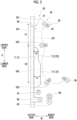
- FIG. 2 is an enlarged view of the surroundings of the fourth transport path 34 of the image forming apparatus 1 shown in Fig. 1 .
- the fourth transport path 34 extends along an up-down direction H of the image forming apparatus 1.
- the paper P of which front and back sides are reversed by passing through the fixing unit 16 is transported in the fourth transport path 34 from an upper side toward a lower side of the image forming apparatus 1 along the up-down direction H.
- the paper transport unit 30 includes a plurality of transport rolls 35 that transport the paper P along the fourth transport path 34.
- the paper transport unit 30 includes an upper transport roll 351 that is provided on the upper side in the up-down direction H in the fourth transport path 34, a lower transport roll 353 that is provided on the lower side in the up-down direction H in the fourth transport path 34, and a middle transport roll 352 that is provided between the upper transport roll 351 and the lower transport roll 353.
- Each transport roll 35 is configured by a pair of roll members that face each other with the fourth transport path 34 sandwiched therebetween and that are rotatable about a rotation shaft.
- the paper transport unit 30 includes a delivery roll 36 that delivers the paper P transported along the fourth transport path 34 by the plurality of transport rolls 35 toward the image forming portion 10.
- a section from the upper transport roll 351 to the middle transport roll 352 will be written as an upper transport path 341, and a section from the middle transport roll 352 to the lower transport roll 353 will be written as a lower transport path 342 in some cases.
- the fourth transport path 34 of the present exemplary embodiment has a curved shape such that each of the upper transport path 341 and the lower transport path 342 inflates to an outer side (the left in Fig. 2 ) of the image forming apparatus 1 in the width direction W.
- the upper transport path 341 between the upper transport roll 351 and the middle transport roll 352 inflates to the outer side of a portion where the paper P is transported by the upper transport roll 351 and a portion where the paper P is transported by the middle transport roll 352 in the width direction W.
- the lower transport path 342 between the middle transport roll 352 and the lower transport roll 353 inflates to the outer side of the portion where the paper P is transported by the middle transport roll 352 and a portion where the paper P is transported by the lower transport roll 353 in the width direction W.
- the fourth transport path 34 of the present exemplary embodiment has a curved shape such that the portion where the paper P is transported by the middle transport roll 352, which is a boundary between the upper transport path 341 and the lower transport path 342, inflates to an inner side (the right in Fig. 2 ) in the width direction W.
- the lower transport path 342 has a shape curved to the outer side in the width direction W, for example, in a case where the paper P is paper having high stiffness such as cardboard, resistance when the paper P has approached the lower transport roll 353 can be reduced.
- a distance X1 between the upper transport roll 351 and the middle transport roll 352 along the up-down direction H is shorter than a smallest length of each of sheets of paper P, which can be transported in the fourth transport path 34 in the image forming apparatus 1, along a paper transport direction (hereinafter, written as a minimum paper length of the image forming apparatus 1). Accordingly, as the paper P is simultaneously transported by the upper transport roll 351 and the middle transport roll 352 in the upper transport path 341, a transport failure of the paper P is unlikely to occur.
- a distance X2 between the middle transport roll 352 and the lower transport roll 353 along the up-down direction H is shorter than the minimum paper length of the image forming apparatus 1. Accordingly, as the paper P is simultaneously transported by the middle transport roll 352 and the lower transport roll 353 in the lower transport path 342, a transport failure of the paper P is unlikely to occur.
- the distance X2 between the middle transport roll 352 and the lower transport roll 353 is longer than the distance X1 between the upper transport roll 351 and the middle transport roll 352 (X2>X1).
- the distance X1 between the upper transport roll 351 and the middle transport roll 352 is a length along the height direction H between roll members positioned on the outer side in the width direction W among the roll members configuring the upper transport roll 351 and the middle transport roll 352.
- the distance X2 between the middle transport roll 352 and the lower transport roll 353 is a length along the height direction H between roll members positioned on the outer side in the width direction W among the roll members configuring the middle transport roll 352 and the lower transport roll 353.
- the lower transport path 342 is longer than the upper transport path 341. Accordingly, it is possible to make the curvature radius of the lower transport path 342 curved to inflate to the outer side in the width direction W even larger, and the transport resistance of the paper P that is transported in the lower transport path 342 can be further reduced.
- each transport roll 35 (in particular, the middle transport roll 352) in the fourth transport path 34 and the second paper supply unit 50 will be described in detail later.
- Fig. 3 is a perspective view showing a configuration of the second paper supply unit 50 of the present exemplary embodiment.
- the second paper supply unit 50 has a feeding unit 51 that is an example of the feeding unit on which the paper P supplied toward the image forming portion 10 is stacked and a paper transport unit 80 that transports the paper P stacked on the feeding unit 51 toward the image forming portion 10.
- the second paper supply unit 50 is a so-called manual feed tray.
- the second paper supply unit 50 sets the paper P having the selected size in order to supply the paper P to the image forming portion 10.
- the second paper supply unit 50 of the present exemplary embodiment can supply atypical paper, for example, from relatively small paper such as a postcard to, for example, A3-sized paper at maximum toward the image forming portion 10.
- the feeding unit 51 of the second paper supply unit 50 is switched between an exposed state where the feeding unit 51 is exposed to the outside of the image forming apparatus 1 such that the paper P can be stacked on the paper stacking unit 52 to be described later and a stored state where the feeding unit 51 is stored in a storing unit 61 formed in the housing 60.
- the opening and closing cover 65 is provided to be rotatable about a hinge 68 that is an example of a rotation shaft attached to the housing 60, opens and closes by rotating about the hinge 68, and switches the feeding unit 51 between the exposed state and the stored state.
- Fig. 3 shows the second paper supply unit 50 in which the feeding unit 51 is in the exposed state.
- the feeding unit 51 includes the paper stacking unit 52 that is an example of a stacking unit on which the paper P is stacked, an expansion unit 55 that expands a place where the paper P is stacked in addition to the paper stacking unit 52, and a paper guide unit 70 that guides the paper P toward the paper transport unit 80.
- the paper stacking unit 52 has a paper stacking surface 521 that is an example of a stacking surface which extends along the width direction W and the depth direction D and which faces the upper side in the height direction H in a case where the feeding unit 51 is in an exposed state.
- the paper stacking unit 52 is a place where a bundle of a plurality of sheets of paper P (hereinafter, written as a paper bundle) transported by the paper transport unit 80 are stacked on the paper stacking surface 521.
- the transport direction in which the paper P is transported is the width direction W of the image forming apparatus 1.
- the paper stacking surface 521 of the paper stacking unit 52 extends along the height direction H and the depth direction D and faces the inner side in the width direction W.
- the paper stacking surface 521 of the paper stacking unit 52 is along the fourth transport path 34 extending in the height direction H.
- the expansion unit 55 is disposed below the paper stacking unit 52 in the height direction H.
- the expansion unit 55 expands a surface for stacking the paper P in addition to the paper stacking surface 521.
- the expansion unit 55 is pulled out to the outer side in the width direction W with respect to the paper stacking unit 52.
- the expansion unit 55 enables placing, for example, A3-sized paper at maximum together with the paper stacking unit 52.
- the expansion unit 55 is stored below the paper stacking unit 52.
- the paper guide unit 70 includes a first guide member 71 that is provided on the front side in the depth direction D of the image forming apparatus 1 and that guides paper stacked on the paper stacking unit 52 and a second guide member 72 that is provided on the back side in the depth direction D and that guides the paper stacked on the paper stacking unit 52 by being paired with the first guide member 71.
- the first guide member 71 and the second guide member 72 are examples of a restricting unit.
- the first guide member 71 and the second guide member 72 have shapes symmetrical with respect to a plane perpendicular to the depth direction D.
- the first guide member 71 and the second guide member 72 have the same outer shape.
- the first guide member 71 and the second guide member 72 are provided to protrude upward in the height direction H from the paper stacking surface 521 of the paper stacking unit 52.
- the first guide member 71 and the second guide member 72 protrude to the inner side in the width direction W from the paper stacking surface 521 of the paper stacking unit 52.
- a height at which the first guide member 71 or the second guide member 72 protrudes from the paper stacking surface 521 will be written as a protruding height of the first guide member 71 or the second guide member 72 in some cases.
- the first guide member 71 includes a downstream guide unit 711 that is positioned on the inner side in the width direction W and that has a first protruding height Y1 and an upstream guide unit 712 that is adjacent to the downstream guide unit 711 on the outer side in the width direction W and that has a second protruding height Y2 smaller than the first protruding height Y1.
- the downstream guide unit 711 is positioned on a downstream side in the transport direction of the paper P stacked on the paper stacking surface 521
- the upstream guide unit 712 is on an upstream side in the transport direction of the paper P to be adjacent to the downstream guide unit 711.
- the downstream guide unit 711 is positioned on a lower side in the up-down direction H, and the upstream guide unit 712 is positioned on an upper side in the up-down direction H with respect to the downstream guide unit 711.
- the upstream guide unit 712 is recessed to the outer side in the width direction W with respect to the downstream guide unit 711.
- the upstream guide unit 712 is an example of a recessed portion in the first guide member 71.
- the second guide member 72 includes a downstream guide unit 721 that is positioned on the inner side in the width direction W and that has the first protruding height Y1 and an upstream guide unit 722 that is adjacent to the downstream guide unit 711 on the outer side in the width direction W and that has the second protruding height Y2.
- the downstream guide unit 721 is positioned on the downstream side in the transport direction of the paper P stacked on the paper stacking surface 521
- the upstream guide unit 722 is on the upstream side in the transport direction of the paper P to be adjacent to the downstream guide unit 721.
- the downstream guide unit 721 is positioned on the lower side in the up-down direction H, and the upstream guide unit 722 is positioned on the upper side in the up-down direction H with respect to the downstream guide unit 721.
- the upstream guide unit 722 is recessed to the outer side in the width direction W with respect to the downstream guide unit 721.
- the upstream guide unit 722 is an example of a recessed portion in the second guide member 72.
- first guide member 71 and the second guide member 72 restrict the position of the paper P on the paper stacking surface 521 by coming into contact with end surfaces of the paper P (or, a paper bundle), which is stacked on the paper stacking surface 521, on the front side and the back side in the depth direction D.
- first guide member 71 and the second guide member 72 are movable on the paper stacking unit 52 in the depth direction D.
- the first guide member 71 and the second guide member 72 move such that a movement amount while one moves and a movement amount while the other moves are the same.
- the paper guide unit 70 restricts the position of the paper P on the paper stacking surface 521 in the depth direction D such that a central portion of the paper P in the depth direction D matches a position on the paper stacking unit 52 determined in advance. Then, as the paper guide unit 70 restricts the position of the paper P on the paper stacking surface 521 in the depth direction D, meandering of the paper P transported from the paper stacking unit 52 to the second transport path 32 is suppressed.
- the paper transport unit 80 includes a pickup roll 81 that picks up the uppermost paper P stacked on the paper stacking unit 52 and a feed roll 82 that sends the paper P picked up by the pickup roll 81 to the downstream side in the transport direction.
- the feed roll 82 sends the paper P picked up by the pickup roll 81 to the second transport path 32.
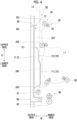
- Fig. 4 is a view showing the relationship between the feeding unit 51 and the fourth transport path 34.
- Fig. 4 corresponds to an enlarged view of the surroundings of the fourth transport path 34 of the image forming apparatus 1 shown in Fig. 1 .
- Fig. 4 corresponds to a view in which the feeding unit 51 and the fourth transport path 34 are viewed along a rotation shaft direction of the roll member configuring each transport roll 35.
- the opening and closing cover 65 is closed with respect to the housing 60, and the feeding unit 51 is in a stored state.
- the middle transport roll 352 in the fourth transport path 34 is disposed at a position that is shifted upward in the height direction H and that overlaps in the width direction W with respect to the first guide member 71 and the second guide member 72 in the feeding unit 51 in a stored state.
- a relationship between the middle transport roll 352 and the first guide member 71 will be generally described, but the same also applies to a relationship between the middle transport roll 352 and the second guide member 72.
- the position of the middle transport roll 352 in the height direction H is at a height H1 of an upper end of the first guide member 71 in the height direction H or greater. More specifically, a tangent line L1 that extends in the width direction W from a lower end of an outer circumference of a roll member of the middle transport roll 352, which is positioned on the outer side in the width direction W, in the height direction H is drawn. As shown in Fig. 4 , the tangent line L1 overlaps the upper end of the first guide member 71 in the height direction H. Further, the rotation shaft of the roll member of the middle transport roll 352, which is positioned on the outer side in the width direction W, is positioned above the upper end of the first guide member 71 in the height direction H.
- the middle transport roll 352 is disposed at a position shifted upward in the height direction H with respect to the first guide member 71 and the second guide member 72 in the feeding unit 51 in a stored state, it is suppressed that the first guide member 71 and the second guide member 72 interfere with the middle transport roll 352 in a case where the feeding unit 51 is switched from an exposed state to the stored state.
- the distance X2 between the middle transport roll 352 and the lower transport roll 353 is longer than the distance X1 between the upper transport roll 351 and the middle transport roll 352.
- the middle transport roll 352 is positioned above the center of the fourth transport path 34 in the height direction H.
- the length of the first guide member 71 in the height direction H in a case where the feeding unit 51 is in a stored state can be made long. Accordingly, compared to a case where the distance X2 between the middle transport roll 352 and the lower transport roll 353 is shorter than the distance X1 between the upper transport roll 351 and the middle transport roll 352, the length of the first guide member 71 in the width direction W in a case where the feeding unit 51 is in an exposed state can be made long.
- the length of the first guide member 71 that comes into contact with an end surface of the paper P, which is stacked on the paper stacking surface 521 and which is transported in the width direction W, can be made long in a case where the feeding unit 51 is in the exposed state. Then, the first guide member 71 makes restricting the position of the paper P on the paper stacking surface 521 in the depth direction D even easier, and thereby meandering of the paper P transported from the paper stacking unit 52 to the second transport path 32 can be further suppressed.
- the middle transport roll 352 in the fourth transport path 34 is disposed at a position that overlaps the first guide member 71 in the feeding unit 51 in a stored state in the width direction W. More specifically, a tangent line L2 that extends in the height direction H from the outer side of an outer circumference of the roll member of the middle transport roll 352, which is positioned on the outer side in the width direction W, in the width direction W is drawn. As shown in Fig. 4 , the tangent line L2 overlaps the downstream guide unit 711 of the first guide member 71. In the example, the tangent line L2 does not overlap the upstream guide unit 712 of the first guide member 71.
- the middle transport roll 352 of the present exemplary embodiment is disposed at a position that overlaps the downstream guide unit 711 of the first guide member 71 in the width direction W and that does not overlap the upstream guide unit 712 in the width direction W.
- the size of the image forming apparatus 1 in the width direction W can be made small, for example, compared to a case where the middle transport roll 352 is disposed at a position that does not overlap the first guide member 71 in the width direction W.
- the middle transport roll 352 since the middle transport roll 352 is disposed at a position shifted upward in the height direction H with respect to the first guide member 71 in the feeding unit 51 in the stored state, the middle transport roll 352 and the first guide member 71 do not interfere with each other even in a case where the middle transport roll 352 is disposed at a position that overlaps the first guide member 71 in the width direction W.
- the upstream guide unit 712 of the first guide member 71 adjacent to the middle transport roll 352 is recessed to the outer side in the width direction W compared to the downstream guide unit 711. Accordingly, compared to a case where the upstream guide unit 712 is not recessed to the outer side in the width direction W with respect to the downstream guide unit 711, the first guide member 71 and the middle transport roll 352 are more unlikely to interfere with each other in a case where the feeding unit 51 is in the stored state.
- a transport member other than the upper transport roll 351, the middle transport roll 352, and the lower transport roll 353 is not provided as the transport roll 35 of the fourth transport path 34, but the fourth transport path 34 may be provided with other transport members.
- the lower transport path 342 curved to inflate toward a feeding unit 51 side is not provided with a transport member other than the middle transport roll 352 and the lower transport roll 353.
- the image forming apparatus 1 can be made smaller in the width direction W.
- the feeding unit 51 is switched between an exposed state and a stored state.
- the first guide member 71 and the second guide member 72 of the feeding unit 51 move integrally with the opening and closing cover 65. Accordingly, in the image forming apparatus 1 described above, relative positions of the first guide member 71 and the second guide member 72 with respect to the opening and closing cover 65 are the same between the feeding unit 51 in the exposed state and the feeding unit 51 in the stored state.
- the opening and closing cover 65 rotates about the hinge 68 to switch the feeding unit 51 between the exposed state and the stored state
- the first guide member 71 and the second guide member 72 are moved with an operation mechanism different from the hinge 68, and thereby relative positions of the first guide member 71 and the second guide member 72 with respect to the opening and closing cover 65 may be changed between the feeding unit 51 in the exposed state and the feeding unit 51 in the stored state.
- Fig. 5 is a view for describing a change in relative positions of the first guide member 71 and the second guide member 72 with respect to the opening and closing cover 65.
- the opening and closing cover 65 opens and closes by rotating about the hinge 68 attached to the housing 60, and the feeding unit 51 is switched between an exposed state and a stored state.
- the first guide member 71 and the second guide member 72 are rotated together with the opening and closing cover 65 and are moved relatively with respect to the opening and closing cover 65 by a link mechanism 69 that rotates about a rotation shaft 690 in response to the rotation of the opening and closing cover 65.
- the rotation shaft 690 of the link mechanism 69 is an example of another rotation shaft, and in the example, the opening and closing cover 65 is disposed at a position shifted downward in the height direction H with respect to the rotating hinge 68.
- the first guide member 71 and the second guide member 72 move relatively to the outer side in the width direction W with respect to the opening and closing cover 65 that extends along the width direction W and the depth direction D in the exposed state.
- the first guide member 71 and the second guide member 72 move relatively to the upstream side in the transport direction of the paper P on the paper stacking unit 52 with respect to the opening and closing cover 65.
- a mechanism for moving the first guide member 71 and the second guide member 72 is not limited to the link mechanism shown in Fig. 5 insofar as the relative positions of the first guide member 71 and the second guide member 72 with respect to the opening and closing cover 65 change in response to the opening and closing operation of the opening and closing cover 65.
- the size of the apparatus can be made small.
- meandering of the recording medium in the feeding unit is likely to be further suppressed while interference between the middle transport member and the restricting unit is suppressed.
- the restricting unit of the feeding unit in response to the opening and closing operation of the opening and closing cover, can be moved relatively with respect to the opening and closing cover.
- the size of the apparatus body can be made smaller while interference between the middle transport member and the restricting unit is suppressed.
Landscapes
- Engineering & Computer Science (AREA)
- Mechanical Engineering (AREA)
- Physics & Mathematics (AREA)
- General Physics & Mathematics (AREA)
- Sheets, Magazines, And Separation Thereof (AREA)
- Manual Feeding Of Sheets (AREA)
Abstract
An image forming apparatus (1) includes an apparatus body (60) that has an image forming portion (10) which forms an image on a recording medium (P), a transport unit (30) that includes a middle transport member (352) which transports the recording medium between an upper end and a lower end of a transport path extending in a height direction of the apparatus body and that transports the recording medium to the image forming portion along the transport path, and a feeding unit (51) that includes a stacking unit (52) which has a stacking surface on which recording media are stacked and a restricting unit (71, 72) which protrudes from the stacking unit and which restricts positions of the recording media stacked on the stacking unit, that is adjacent to the transport path in a width direction (W) of the apparatus body, and that is switched between a stored state where the stacking unit is stored inside the apparatus body such that the stacking surface is along the transport path and an exposed state where the stacking unit is exposed to an outside of the apparatus body such that the recording media are capable of being stacked on the stacking surface, in which the middle transport member of the transport unit is disposed at a position that is shifted upward in the height direction and that overlaps in the width direction with respect to the restricting unit in the feeding unit in the stored state.
Description
- The present invention relates to an image forming apparatus.
-
JP2014-144851A - There is an image forming apparatus including a feeding unit that is adjacent to a transport path, in which a recording medium is transported along a height direction of an apparatus body, in a width direction of the apparatus body and that is switched between a stored state where a stacking unit is stored inside the apparatus body such that a stacking surface on which recording media are stacked is along the transport path and an exposed state where the stacking unit is exposed to the outside of the apparatus body such that the recording media can be stacked.
- In such an image forming apparatus, in a case where the feeding unit is in the stored state, for example, it is preferable that a transport member that transports the recording media and a restricting unit that restricts the positions of the recording media stacked on the stacking unit, which are in the transport path adjacent to the feeding unit, are disposed so as not to interfere with each other. However, in a case where the transport member and the restricting unit are disposed at positions shifted from each other in the width direction of the apparatus body such that the transport member and the restricting unit do not interfere with each other, an increase in the size of the apparatus in the width direction is likely to be achieved.
- An object of the present invention is to make the size of the apparatus small compared to a case where the transport member that transports the recording media is disposed at a position shifted with respect to the restricting unit in the width direction.
- According to a first aspect of the present invention, there is provided an image forming apparatus including an apparatus body that has an image forming portion which forms an image on a recording medium, a transport unit that includes a middle transport member which transports the recording medium between an upper end and a lower end of a transport path extending in a height direction of the apparatus body and that transports the recording medium to the image forming portion along the transport path, and a feeding unit that includes a stacking unit which has a stacking surface on which recording media are stacked and a restricting unit which protrudes from the stacking unit and which restricts positions of the recording media stacked on the stacking unit, that is adjacent to the transport path in a width direction of the apparatus body, and that is switched between a stored state where the stacking unit is stored inside the apparatus body such that the stacking surface is along the transport path and an exposed state where the stacking unit is exposed to an outside of the apparatus body such that the recording media are capable of being stacked on the stacking surface, in which the middle transport member of the transport unit is disposed at a position that is shifted upward in the height direction and that overlaps in the width direction with respect to the restricting unit in the feeding unit in the stored state.
- According to a second aspect of the present invention, in the image forming apparatus according to the first aspect, the transport unit may further include a lower transport member that is provided below the middle transport member in the transport path and that transports the recording medium transported by the middle transport member toward the image forming portion, and the transport path between the middle transport member and the lower transport member may be curved to protrude toward an outer side of the apparatus body.
- According to a third aspect of the present invention, in the image forming apparatus according to the second aspect, the transport unit may not be provided with another transport member that transports the recording medium in the transport path between the middle transport member and the lower transport member.
- According to a fourth aspect of the present invention, in the image forming apparatus according to the second or third aspect, the transport unit may further include an upper transport member that is provided above the middle transport member in the transport path and that transports the recording medium toward the middle transport member, and a distance between the middle transport member and the lower transport member may be longer than a distance between the upper transport member and the middle transport member.
- According to a fifth aspect of the present invention, in the image forming apparatus according to the fourth aspect, the distance between the middle transport member and the lower transport member may be shorter than a length of a minimum recording medium transported in the transport path in a transport direction.
- According to a sixth aspect of the present invention, in the image forming apparatus according to any one of the first to fifth aspects, the middle transport member of the transport unit may transport the recording medium above a center of the transport path in the height direction.
- According to a seventh aspect of the present invention, the image forming apparatus according to any one of the first to fifth aspects may further include an opening and closing cover that opens and closes with respect to the apparatus body, in which the feeding unit may be switched between the stored state and the exposed state in response to an opening and closing operation of the opening and closing cover, and a relative position of the restricting unit with respect to the opening and closing cover may differ between the stored state and the exposed state.
- According to an eighth aspect of the present invention, in the image forming apparatus according to the seventh aspect, the opening and closing cover may open and close with respect to the apparatus body by rotating about a rotation shaft, and in response to the opening and closing operation of the opening and closing cover, the feeding unit may rotate about another rotation shaft shifted from the rotation shaft in the height direction or the width direction and may be switched between the stored state and the exposed state.
- According to a ninth aspect of the present invention, in the image forming apparatus according to the first aspect, in the feeding unit in the stored state, a lower portion of the restricting unit in the height direction may protrude to an inner side of the apparatus body compared to an upper portion of the restricting unit in the height direction.
- According to a tenth aspect of the present invention, in the image forming apparatus according to the first aspect, the restricting unit of the feeding unit in the stored state may have a recessed portion that is recessed toward the outside of the apparatus body, and the transport unit may be disposed at a position where the middle transport member is adj acent to the recessed portion in the restricting unit in the width direction and the transport path is curved toward an inner side of the apparatus body.
- According to an eleventh aspect of the present invention, in the image forming apparatus according to the first aspect, the middle transport member of the transport unit may be a roll member that rotates about a rotation shaft, in a case of being viewed in a rotation shaft direction, a tangent line that extends in the width direction from a lower end of an outer circumference of the roll member in the height direction may overlap an upper end of the restricting unit in the stored state in the height direction, and the rotation shaft may be positioned above the upper end of the restricting unit in the stored state in the height direction.
- According to the first aspect of the present invention, compared to a case where the transport member that transports the recording medium is disposed at a position shifted in the width direction with respect to the restricting unit, the size of the apparatus can be made small.
- According to the second aspect of the present invention, compared to a case where the transport path between the middle transport member and the lower transport member does not protrude toward the outer side of the apparatus body, transport resistance in a case where the recording medium is transported in the transport path is low.
- According to the third aspect of the present invention, compared to a case where another transport member is provided between the middle transport member and the lower transport member, an increase in the size of the apparatus in order to avoid interference between the other transport member and the restricting unit is suppressed.
- According to the fourth aspect of the present invention, compared to a case where the distance between the middle transport member and the lower transport member is shorter than the distance between the upper transport member and the middle transport member, transport resistance in a case where the recording medium is transported in the transport path is low.
- According to the fifth aspect of the present invention, compared to a case where the distance between the middle transport member and the lower transport member is longer than the length of the minimum recording medium in the transport direction, a transport failure of the recording medium is suppressed.
- According to the sixth aspect of the present invention, compared to a case where the middle transport member transports the recording medium below the center of the transport path in the height direction, meandering of the recording medium in the feeding unit can be further suppressed.
- According to the seventh aspect of the present invention, meandering of the recording medium in the feeding unit is likely to be further suppressed while interference between the middle transport member and the restricting unit is suppressed.
- According to the eighth aspect of the present invention, in response to the opening and closing operation of the opening and closing cover, the restricting unit of the feeding unit can be moved relatively with respect to the opening and closing cover.
- According to the ninth aspect of the present invention, compared to a case where the lower portion of the restricting unit in the height direction does not protrude to the inner side of the apparatus body compared to the upper portion of the restricting unit in the height direction, meandering of the recording medium in the feeding unit is likely to be further suppressed while interference between the middle transport member and the restricting unit is suppressed.
- According to the tenth aspect of the present invention, compared to a case where the middle transport member is not disposed at the position where the transport path is curved to the inner side of the apparatus body, the size of the apparatus body can be made smaller while interference between the middle transport member and the restricting unit is suppressed.
- According to the eleventh aspect of the present invention, compared to a case where the tangent line that extends in the width direction from the lower end of the outer circumference of the roll member in the height direction does not overlap the upper end of the restricting unit in the stored state in the height direction, meandering of the recording medium in the feeding unit is more likely to be suppressed while interference between the middle transport member and the restricting unit is suppressed.
- Exemplary embodiment(s) of the present invention will be described in detail based on the following figures, wherein:
-
Fig. 1 is an overall view of an image forming apparatus to which the present exemplary embodiment is applied; -
Fig. 2 is an enlarged view of the surroundings of a fourth transport path of the image forming apparatus shown inFig. 1 ; -
Fig. 3 is a perspective view showing a configuration of a second paper supply unit of the present exemplary embodiment; -
Fig. 4 is a view showing a relationship between a feeding unit and the fourth transport path; and -
Fig. 5 is a view for describing a change in relative positions of a first guide member and a second guide member with respect to an opening and closing cover. - Hereinafter, an exemplary embodiment of the present invention will be described in detail with reference to the accompanying drawings.
-
Fig. 1 is an overall view of animage forming apparatus 1 to which the present exemplary embodiment is applied. - The
image forming apparatus 1 includes animage forming portion 10 that performs image forming corresponding to image data of each color, animage reading device 20 that reads an image, apaper transport unit 30 that transports paper P which is a recording medium, and a firstpaper supply unit 40 that supplies the paper P to theimage forming portion 10. In addition, theimage forming apparatus 1 includes a secondpaper supply unit 50 that is an example of a feeding unit which supplies the paper P to theimage forming portion 10. Further, theimage forming apparatus 1 includes ahousing 60 that accommodates theimage forming portion 10, thepaper transport unit 30, and the firstpaper supply unit 40. Although details will be described later, thehousing 60 is provided with an opening andclosing cover 65 that is provided to be openable and closable and that switches a paper stacking unit 52 (seeFig. 2 ) of the secondpaper supply unit 50 between a stored state and an exposed state. - In the description of the present exemplary embodiment, a direction in which a front side and a back side of the page are linked to each other in the
image forming apparatus 1 shown inFig. 1 will be defined as a depth direction D of theimage forming apparatus 1. In addition, in theimage forming apparatus 1 shown inFig. 1 , a right-left direction of the page will be defined as a width direction W of theimage forming apparatus 1, and an up-down direction of the page will be defined as a height direction H of theimage forming apparatus 1. - The
image forming portion 10 includes four image forming units 11 (11Y, 11M, 11C, 11K) disposed in parallel at regular intervals. Each of theimage forming units photosensitive drum 12 that forms an electrostatic latent image and that holds a toner image and forms the toner image through an electrophotographic method. Theimage forming units - In addition, the
image forming portion 10 includes anintermediate transfer belt 13 to which a toner image of each color formed on thephotosensitive drum 12 of eachimage forming unit 11 is transferred. In addition, theimage forming portion 10 includes aprimary transfer roll 14 that sequentially transfers (primarily transfers) a toner image of each color formed by eachimage forming unit 11 to theintermediate transfer belt 13. Further, theimage forming portion 10 includes asecondary transfer unit 15 that collectively transfers (secondarily transfers) a toner image of each color formed by being superimposed onto theintermediate transfer belt 13 to the paper P and afixing unit 16 that fixes the secondarily transferred toner image of each color to the paper P. - The
image reading device 20 reads an image formed on a document and transmits the read data to a control unit (not shown) of theimage forming portion 10 or other devices (not shown) provided outside theimage forming apparatus 1. In addition, theimage reading device 20 includes apaper sending device 21 that transports the paper P stacked on astacking unit 21S one by one in turn toward a reading sensor provided at theimage reading device 20 in order to read an image on the paper P. - The
paper transport unit 30 includes a first transport path 31 in which the paper P supplied from the firstpaper supply unit 40 is transported toward thesecondary transfer unit 15, asecond transport path 32 in which the paper P supplied from the secondpaper supply unit 50 is transported toward thesecondary transfer unit 15, and athird transport path 33 in which the paper P is transported from thesecondary transfer unit 15 to thefixing unit 16 and is discharged to the outside of theimage forming apparatus 1. Further, thepaper transport unit 30 has afourth transport path 34 that branches from thethird transport path 33 and in which the paper P, of which front and back sides are reversed by passing through thefixing unit 16, is again transported to thesecondary transfer unit 15. - The first transport path 31, the
second transport path 32, thethird transport path 33, and thefourth transport path 34 of thepaper transport unit 30 are provided with a plurality of transport rolls that transport the paper P. - The first
paper supply unit 40 includes a plurality of paperaccommodating units 41. In addition, eachpaper accommodating unit 41 is provided with asending roll 42 that sends out the accommodated paper P. The firstpaper supply unit 40 sends out the paper P from eachpaper accommodating unit 41 with thesending roll 42 and supplies the paper P to thepaper transport unit 30. - Next, the
fourth transport path 34 in thepaper transport unit 30 will be described.Fig. 2 is an enlarged view of the surroundings of thefourth transport path 34 of theimage forming apparatus 1 shown inFig. 1 . - As shown in
Fig. 2 , thefourth transport path 34 extends along an up-down direction H of theimage forming apparatus 1. In addition, the paper P of which front and back sides are reversed by passing through the fixing unit 16 (seeFig. 1 ) is transported in thefourth transport path 34 from an upper side toward a lower side of theimage forming apparatus 1 along the up-down direction H. - As shown in
Fig. 2 , thepaper transport unit 30 includes a plurality of transport rolls 35 that transport the paper P along thefourth transport path 34. Specifically, thepaper transport unit 30 includes anupper transport roll 351 that is provided on the upper side in the up-down direction H in thefourth transport path 34, alower transport roll 353 that is provided on the lower side in the up-down direction H in thefourth transport path 34, and amiddle transport roll 352 that is provided between theupper transport roll 351 and thelower transport roll 353. Eachtransport roll 35 is configured by a pair of roll members that face each other with thefourth transport path 34 sandwiched therebetween and that are rotatable about a rotation shaft. - Further, the
paper transport unit 30 includes adelivery roll 36 that delivers the paper P transported along thefourth transport path 34 by the plurality of transport rolls 35 toward theimage forming portion 10. - Hereinafter, in the
fourth transport path 34, a section from theupper transport roll 351 to themiddle transport roll 352 will be written as anupper transport path 341, and a section from themiddle transport roll 352 to thelower transport roll 353 will be written as alower transport path 342 in some cases. - The
fourth transport path 34 of the present exemplary embodiment has a curved shape such that each of theupper transport path 341 and thelower transport path 342 inflates to an outer side (the left inFig. 2 ) of theimage forming apparatus 1 in the width direction W. In addition, theupper transport path 341 between theupper transport roll 351 and themiddle transport roll 352 inflates to the outer side of a portion where the paper P is transported by theupper transport roll 351 and a portion where the paper P is transported by themiddle transport roll 352 in the width direction W. Similarly, thelower transport path 342 between themiddle transport roll 352 and thelower transport roll 353 inflates to the outer side of the portion where the paper P is transported by themiddle transport roll 352 and a portion where the paper P is transported by thelower transport roll 353 in the width direction W. - In addition, the
fourth transport path 34 of the present exemplary embodiment has a curved shape such that the portion where the paper P is transported by themiddle transport roll 352, which is a boundary between theupper transport path 341 and thelower transport path 342, inflates to an inner side (the right inFig. 2 ) in the width direction W. - In the present exemplary embodiment, as the
lower transport path 342 has a shape curved to the outer side in the width direction W, for example, in a case where the paper P is paper having high stiffness such as cardboard, resistance when the paper P has approached thelower transport roll 353 can be reduced. - As shown in
Fig. 2 , a distance X1 between theupper transport roll 351 and themiddle transport roll 352 along the up-down direction H is shorter than a smallest length of each of sheets of paper P, which can be transported in thefourth transport path 34 in theimage forming apparatus 1, along a paper transport direction (hereinafter, written as a minimum paper length of the image forming apparatus 1). Accordingly, as the paper P is simultaneously transported by theupper transport roll 351 and themiddle transport roll 352 in theupper transport path 341, a transport failure of the paper P is unlikely to occur. - Similarly, a distance X2 between the
middle transport roll 352 and thelower transport roll 353 along the up-down direction H is shorter than the minimum paper length of theimage forming apparatus 1. Accordingly, as the paper P is simultaneously transported by themiddle transport roll 352 and thelower transport roll 353 in thelower transport path 342, a transport failure of the paper P is unlikely to occur. - Herein, in the
fourth transport path 34 of the present exemplary embodiment, the distance X2 between themiddle transport roll 352 and thelower transport roll 353 is longer than the distance X1 between theupper transport roll 351 and the middle transport roll 352 (X2>X1). The distance X1 between theupper transport roll 351 and themiddle transport roll 352 is a length along the height direction H between roll members positioned on the outer side in the width direction W among the roll members configuring theupper transport roll 351 and themiddle transport roll 352. Similarly, the distance X2 between themiddle transport roll 352 and thelower transport roll 353 is a length along the height direction H between roll members positioned on the outer side in the width direction W among the roll members configuring themiddle transport roll 352 and thelower transport roll 353. - As the distance X2 between the
middle transport roll 352 and thelower transport roll 353 is longer than the distance X1 between theupper transport roll 351 and themiddle transport roll 352 in thefourth transport path 34, thelower transport path 342 is longer than theupper transport path 341. Accordingly, it is possible to make the curvature radius of thelower transport path 342 curved to inflate to the outer side in the width direction W even larger, and the transport resistance of the paper P that is transported in thelower transport path 342 can be further reduced. - A relationship between each transport roll 35 (in particular, the middle transport roll 352) in the
fourth transport path 34 and the secondpaper supply unit 50 will be described in detail later. -
Fig. 3 is a perspective view showing a configuration of the secondpaper supply unit 50 of the present exemplary embodiment. - As shown in
Fig. 3 , the secondpaper supply unit 50 has afeeding unit 51 that is an example of the feeding unit on which the paper P supplied toward theimage forming portion 10 is stacked and apaper transport unit 80 that transports the paper P stacked on thefeeding unit 51 toward theimage forming portion 10. - The second
paper supply unit 50 is a so-called manual feed tray. In addition, in a case where image forming is performed on the paper P having a size selected by a user, the secondpaper supply unit 50 sets the paper P having the selected size in order to supply the paper P to theimage forming portion 10. The secondpaper supply unit 50 of the present exemplary embodiment can supply atypical paper, for example, from relatively small paper such as a postcard to, for example, A3-sized paper at maximum toward theimage forming portion 10. - In response to an opening and closing operation of the opening and closing
cover 65 that is openable and closable with respect to the housing 60 (seeFig. 1 ), thefeeding unit 51 of the secondpaper supply unit 50 is switched between an exposed state where thefeeding unit 51 is exposed to the outside of theimage forming apparatus 1 such that the paper P can be stacked on thepaper stacking unit 52 to be described later and a stored state where thefeeding unit 51 is stored in a storing unit 61 formed in thehousing 60. In addition, the opening and closingcover 65 is provided to be rotatable about ahinge 68 that is an example of a rotation shaft attached to thehousing 60, opens and closes by rotating about thehinge 68, and switches thefeeding unit 51 between the exposed state and the stored state. -
Fig. 3 shows the secondpaper supply unit 50 in which thefeeding unit 51 is in the exposed state. - The
feeding unit 51 includes thepaper stacking unit 52 that is an example of a stacking unit on which the paper P is stacked, anexpansion unit 55 that expands a place where the paper P is stacked in addition to thepaper stacking unit 52, and apaper guide unit 70 that guides the paper P toward thepaper transport unit 80. - The
paper stacking unit 52 has apaper stacking surface 521 that is an example of a stacking surface which extends along the width direction W and the depth direction D and which faces the upper side in the height direction H in a case where thefeeding unit 51 is in an exposed state. In addition, thepaper stacking unit 52 is a place where a bundle of a plurality of sheets of paper P (hereinafter, written as a paper bundle) transported by thepaper transport unit 80 are stacked on thepaper stacking surface 521. In thepaper stacking unit 52 of the present exemplary embodiment, the transport direction in which the paper P is transported is the width direction W of theimage forming apparatus 1. - Although details will be described later, as shown in
Fig. 2 , in a case where thefeeding unit 51 is in a stored state, thepaper stacking surface 521 of thepaper stacking unit 52 extends along the height direction H and the depth direction D and faces the inner side in the width direction W. In addition, in a case where thefeeding unit 51 is in the stored state, thepaper stacking surface 521 of thepaper stacking unit 52 is along thefourth transport path 34 extending in the height direction H. - In a case where the
feeding unit 51 is in an exposed state, theexpansion unit 55 is disposed below thepaper stacking unit 52 in the height direction H. In addition, in a state of being pulled out with respect to thepaper stacking unit 52, theexpansion unit 55 expands a surface for stacking the paper P in addition to thepaper stacking surface 521. In the example, theexpansion unit 55 is pulled out to the outer side in the width direction W with respect to thepaper stacking unit 52. In a state of being pulled out, theexpansion unit 55 enables placing, for example, A3-sized paper at maximum together with thepaper stacking unit 52. On the other hand, in a case where the user does not use theexpansion unit 55, theexpansion unit 55 is stored below thepaper stacking unit 52. - The
paper guide unit 70 includes afirst guide member 71 that is provided on the front side in the depth direction D of theimage forming apparatus 1 and that guides paper stacked on thepaper stacking unit 52 and asecond guide member 72 that is provided on the back side in the depth direction D and that guides the paper stacked on thepaper stacking unit 52 by being paired with thefirst guide member 71. Thefirst guide member 71 and thesecond guide member 72 are examples of a restricting unit. In the present exemplary embodiment, thefirst guide member 71 and thesecond guide member 72 have shapes symmetrical with respect to a plane perpendicular to the depth direction D. In addition, in a case of being viewed along the depth direction D, thefirst guide member 71 and thesecond guide member 72 have the same outer shape. - In a case where the
feeding unit 51 is in an exposed state, thefirst guide member 71 and thesecond guide member 72 are provided to protrude upward in the height direction H from thepaper stacking surface 521 of thepaper stacking unit 52. - Although details will be described later, as shown in
Fig. 2 , in a case where thefeeding unit 51 is in a stored state, thefirst guide member 71 and thesecond guide member 72 protrude to the inner side in the width direction W from thepaper stacking surface 521 of thepaper stacking unit 52. - Hereinafter, a height at which the
first guide member 71 or thesecond guide member 72 protrudes from thepaper stacking surface 521 will be written as a protruding height of thefirst guide member 71 or thesecond guide member 72 in some cases. - To describe specifically, in a case where the
feeding unit 51 is in an exposed state, thefirst guide member 71 includes adownstream guide unit 711 that is positioned on the inner side in the width direction W and that has a first protruding height Y1 and anupstream guide unit 712 that is adjacent to thedownstream guide unit 711 on the outer side in the width direction W and that has a second protruding height Y2 smaller than the first protruding height Y1. In thefirst guide member 71, thedownstream guide unit 711 is positioned on a downstream side in the transport direction of the paper P stacked on thepaper stacking surface 521, and theupstream guide unit 712 is on an upstream side in the transport direction of the paper P to be adjacent to thedownstream guide unit 711. In addition, in a case where thefeeding unit 51 is in a stored state, thedownstream guide unit 711 is positioned on a lower side in the up-down direction H, and theupstream guide unit 712 is positioned on an upper side in the up-down direction H with respect to thedownstream guide unit 711. - In addition, in a case where the
feeding unit 51 is in the stored state, in thefirst guide member 71, theupstream guide unit 712 is recessed to the outer side in the width direction W with respect to thedownstream guide unit 711. Theupstream guide unit 712 is an example of a recessed portion in thefirst guide member 71. - Similarly, in a case where the
feeding unit 51 is in an exposed state, thesecond guide member 72 includes adownstream guide unit 721 that is positioned on the inner side in the width direction W and that has the first protruding height Y1 and anupstream guide unit 722 that is adjacent to thedownstream guide unit 711 on the outer side in the width direction W and that has the second protruding height Y2. In thesecond guide member 72, thedownstream guide unit 721 is positioned on the downstream side in the transport direction of the paper P stacked on thepaper stacking surface 521, and theupstream guide unit 722 is on the upstream side in the transport direction of the paper P to be adjacent to thedownstream guide unit 721. In addition, in a case where thefeeding unit 51 is in a stored state, thedownstream guide unit 721 is positioned on the lower side in the up-down direction H, and theupstream guide unit 722 is positioned on the upper side in the up-down direction H with respect to thedownstream guide unit 721. - In addition, in a case where the
feeding unit 51 is in the stored state, in thesecond guide member 72, theupstream guide unit 722 is recessed to the outer side in the width direction W with respect to thedownstream guide unit 721. Theupstream guide unit 722 is an example of a recessed portion in thesecond guide member 72. - In addition, the
first guide member 71 and thesecond guide member 72 restrict the position of the paper P on thepaper stacking surface 521 by coming into contact with end surfaces of the paper P (or, a paper bundle), which is stacked on thepaper stacking surface 521, on the front side and the back side in the depth direction D. - In addition, the
first guide member 71 and thesecond guide member 72 are movable on thepaper stacking unit 52 in the depth direction D. In the present exemplary embodiment, thefirst guide member 71 and thesecond guide member 72 move such that a movement amount while one moves and a movement amount while the other moves are the same. Accordingly, thepaper guide unit 70 restricts the position of the paper P on thepaper stacking surface 521 in the depth direction D such that a central portion of the paper P in the depth direction D matches a position on thepaper stacking unit 52 determined in advance. Then, as thepaper guide unit 70 restricts the position of the paper P on thepaper stacking surface 521 in the depth direction D, meandering of the paper P transported from thepaper stacking unit 52 to thesecond transport path 32 is suppressed. - With reference to
Fig. 1 as well, thepaper transport unit 80 includes apickup roll 81 that picks up the uppermost paper P stacked on thepaper stacking unit 52 and afeed roll 82 that sends the paper P picked up by thepickup roll 81 to the downstream side in the transport direction. Thefeed roll 82 sends the paper P picked up by thepickup roll 81 to thesecond transport path 32. - Next, a relationship between the feeding
unit 51 in a stored state and thefourth transport path 34 will be described in more detail. -
Fig. 4 is a view showing the relationship between the feedingunit 51 and thefourth transport path 34. As inFig. 2 ,Fig. 4 corresponds to an enlarged view of the surroundings of thefourth transport path 34 of theimage forming apparatus 1 shown inFig. 1 . In addition,Fig. 4 corresponds to a view in which thefeeding unit 51 and thefourth transport path 34 are viewed along a rotation shaft direction of the roll member configuring eachtransport roll 35. Herein, the opening and closingcover 65 is closed with respect to thehousing 60, and thefeeding unit 51 is in a stored state. - As shown in
Fig. 4 , themiddle transport roll 352 in thefourth transport path 34 is disposed at a position that is shifted upward in the height direction H and that overlaps in the width direction W with respect to thefirst guide member 71 and thesecond guide member 72 in thefeeding unit 51 in a stored state. Hereinafter, a relationship between themiddle transport roll 352 and thefirst guide member 71 will be generally described, but the same also applies to a relationship between themiddle transport roll 352 and thesecond guide member 72. - In the
image forming apparatus 1 of the present exemplary embodiment, in a case where thefeeding unit 51 is in a stored state, the position of themiddle transport roll 352 in the height direction H is at a height H1 of an upper end of thefirst guide member 71 in the height direction H or greater. More specifically, a tangent line L1 that extends in the width direction W from a lower end of an outer circumference of a roll member of themiddle transport roll 352, which is positioned on the outer side in the width direction W, in the height direction H is drawn. As shown inFig. 4 , the tangent line L1 overlaps the upper end of thefirst guide member 71 in the height direction H. Further, the rotation shaft of the roll member of themiddle transport roll 352, which is positioned on the outer side in the width direction W, is positioned above the upper end of thefirst guide member 71 in the height direction H. - As described above, in the
image forming apparatus 1 of the present exemplary embodiment, as themiddle transport roll 352 is disposed at a position shifted upward in the height direction H with respect to thefirst guide member 71 and thesecond guide member 72 in thefeeding unit 51 in a stored state, it is suppressed that thefirst guide member 71 and thesecond guide member 72 interfere with themiddle transport roll 352 in a case where thefeeding unit 51 is switched from an exposed state to the stored state. - In addition, as shown in
Fig. 2 , in theimage forming apparatus 1 of the present exemplary embodiment, the distance X2 between themiddle transport roll 352 and thelower transport roll 353 is longer than the distance X1 between theupper transport roll 351 and themiddle transport roll 352. In other words, in theimage forming apparatus 1 of the present exemplary embodiment, themiddle transport roll 352 is positioned above the center of thefourth transport path 34 in the height direction H. - Accordingly, compared to a case where the distance X2 between the
middle transport roll 352 and thelower transport roll 353 is shorter than the distance X1 between theupper transport roll 351 and themiddle transport roll 352, the length of thefirst guide member 71 in the height direction H in a case where thefeeding unit 51 is in a stored state can be made long. Accordingly, compared to a case where the distance X2 between themiddle transport roll 352 and thelower transport roll 353 is shorter than the distance X1 between theupper transport roll 351 and themiddle transport roll 352, the length of thefirst guide member 71 in the width direction W in a case where thefeeding unit 51 is in an exposed state can be made long. - As a result, in the
image forming apparatus 1 of the present exemplary embodiment, the length of thefirst guide member 71 that comes into contact with an end surface of the paper P, which is stacked on thepaper stacking surface 521 and which is transported in the width direction W, can be made long in a case where thefeeding unit 51 is in the exposed state. Then, thefirst guide member 71 makes restricting the position of the paper P on thepaper stacking surface 521 in the depth direction D even easier, and thereby meandering of the paper P transported from thepaper stacking unit 52 to thesecond transport path 32 can be further suppressed. - Further, in the
image forming apparatus 1 of the present exemplary embodiment, themiddle transport roll 352 in thefourth transport path 34 is disposed at a position that overlaps thefirst guide member 71 in thefeeding unit 51 in a stored state in the width direction W. More specifically, a tangent line L2 that extends in the height direction H from the outer side of an outer circumference of the roll member of themiddle transport roll 352, which is positioned on the outer side in the width direction W, in the width direction W is drawn. As shown inFig. 4 , the tangent line L2 overlaps thedownstream guide unit 711 of thefirst guide member 71. In the example, the tangent line L2 does not overlap theupstream guide unit 712 of thefirst guide member 71. In addition, themiddle transport roll 352 of the present exemplary embodiment is disposed at a position that overlaps thedownstream guide unit 711 of thefirst guide member 71 in the width direction W and that does not overlap theupstream guide unit 712 in the width direction W. - As described above, in the
image forming apparatus 1 of the present exemplary embodiment, as themiddle transport roll 352 is disposed at a position that overlaps thefirst guide member 71 of thefeeding unit 51 in a stored state in the width direction W, the size of theimage forming apparatus 1 in the width direction W can be made small, for example, compared to a case where themiddle transport roll 352 is disposed at a position that does not overlap thefirst guide member 71 in the width direction W. - Herein, as described above, since the
middle transport roll 352 is disposed at a position shifted upward in the height direction H with respect to thefirst guide member 71 in thefeeding unit 51 in the stored state, themiddle transport roll 352 and thefirst guide member 71 do not interfere with each other even in a case where themiddle transport roll 352 is disposed at a position that overlaps thefirst guide member 71 in the width direction W. - In addition, in the
image forming apparatus 1 of the present exemplary embodiment, in a case where thefeeding unit 51 is in a stored state, theupstream guide unit 712 of thefirst guide member 71 adjacent to themiddle transport roll 352 is recessed to the outer side in the width direction W compared to thedownstream guide unit 711. Accordingly, compared to a case where theupstream guide unit 712 is not recessed to the outer side in the width direction W with respect to thedownstream guide unit 711, thefirst guide member 71 and themiddle transport roll 352 are more unlikely to interfere with each other in a case where thefeeding unit 51 is in the stored state. - In the exemplary embodiment described above, a transport member other than the
upper transport roll 351, themiddle transport roll 352, and thelower transport roll 353 is not provided as thetransport roll 35 of thefourth transport path 34, but thefourth transport path 34 may be provided with other transport members. However, from a viewpoint of suppressing interference between thetransport roll 35 of thefourth transport path 34 and thefirst guide member 71 and thesecond guide member 72 in thefeeding unit 51 in a stored state, for example, it is preferable that thelower transport path 342 curved to inflate toward afeeding unit 51 side is not provided with a transport member other than themiddle transport roll 352 and thelower transport roll 353. In this case, compared to a case where thelower transport path 342 is provided with a transport member other than themiddle transport roll 352 and thelower transport roll 353, theimage forming apparatus 1 can be made smaller in the width direction W. - In the
image forming apparatus 1 described above, as the opening and closingcover 65 rotates about thehinge 68, thefeeding unit 51 is switched between an exposed state and a stored state. In addition, in a case where the opening and closingcover 65 rotates about thehinge 68, thefirst guide member 71 and thesecond guide member 72 of thefeeding unit 51 move integrally with the opening and closingcover 65. Accordingly, in theimage forming apparatus 1 described above, relative positions of thefirst guide member 71 and thesecond guide member 72 with respect to the opening and closingcover 65 are the same between the feedingunit 51 in the exposed state and thefeeding unit 51 in the stored state. - However, in the
image forming apparatus 1, for example, as the opening and closingcover 65 rotates about thehinge 68 to switch thefeeding unit 51 between the exposed state and the stored state, thefirst guide member 71 and thesecond guide member 72 are moved with an operation mechanism different from thehinge 68, and thereby relative positions of thefirst guide member 71 and thesecond guide member 72 with respect to the opening and closingcover 65 may be changed between the feedingunit 51 in the exposed state and thefeeding unit 51 in the stored state. -
Fig. 5 is a view for describing a change in relative positions of thefirst guide member 71 and thesecond guide member 72 with respect to the opening and closingcover 65. - As in the example described above, the opening and closing
cover 65 opens and closes by rotating about thehinge 68 attached to thehousing 60, and thefeeding unit 51 is switched between an exposed state and a stored state. - In addition, in the example shown in
Fig. 5 , thefirst guide member 71 and thesecond guide member 72 are rotated together with the opening and closingcover 65 and are moved relatively with respect to the opening and closingcover 65 by alink mechanism 69 that rotates about arotation shaft 690 in response to the rotation of the opening and closingcover 65. Therotation shaft 690 of thelink mechanism 69 is an example of another rotation shaft, and in the example, the opening and closingcover 65 is disposed at a position shifted downward in the height direction H with respect to therotating hinge 68. - More specifically, as shown in
Fig. 5 , in a case where the opening and closingcover 65 rotates about thehinge 68 to switch thefeeding unit 51 from a stored state to an exposed state, thefirst guide member 71 and thesecond guide member 72 move relatively to the outer side in the width direction W with respect to the opening and closingcover 65 that extends along the width direction W and the depth direction D in the exposed state. In other words, in a case where the opening and closingcover 65 is switched from the stored state to the exposed state, thefirst guide member 71 and thesecond guide member 72 move relatively to the upstream side in the transport direction of the paper P on thepaper stacking unit 52 with respect to the opening and closingcover 65. - Accordingly, in the
feeding unit 51 shown inFig. 5 , it is possible to restrict the position of the paper P stacked on thepaper stacking unit 52 in the depth direction D from further upstream side in the transport direction compared to a case where the relative positions of thefirst guide member 71 and thesecond guide member 72 with respect to the opening and closingcover 65 do not change in response to the rotation of the opening and closingcover 65. As a result, meandering of the paper P transported from thepaper stacking unit 52 to thesecond transport path 32 can be further suppressed. - A mechanism for moving the
first guide member 71 and thesecond guide member 72 is not limited to the link mechanism shown inFig. 5 insofar as the relative positions of thefirst guide member 71 and thesecond guide member 72 with respect to the opening and closingcover 65 change in response to the opening and closing operation of the opening and closingcover 65. - Although the exemplary embodiment of the present invention has been described hereinbefore, the present invention is not limited to the exemplary embodiment described above. In addition, effects of the exemplary embodiment of the present invention are not limited to the exemplary embodiment described above. Various modifications and alternative configurations are included in the present invention without departing from the technical scope of the present invention.
-
- (((1))) An image forming apparatus comprising:
- an apparatus body that has an image forming portion which forms an image on a recording medium;
- a transport unit that includes a middle transport member which transports the recording medium between an upper end and a lower end of a transport path extending in a height direction of the apparatus body and that transports the recording medium to the image forming portion along the transport path; and
- a feeding unit that includes a stacking unit which has a stacking surface on which recording media are stacked and a restricting unit which protrudes from the stacking unit and which restricts positions of the recording media stacked on the stacking unit, that is adjacent to the transport path in a width direction of the apparatus body, and that is switched between a stored state where the stacking unit is stored inside the apparatus body such that the stacking surface is along the transport path and an exposed state where the stacking unit is exposed to an outside of the apparatus body such that the recording media are capable of being stacked on the stacking surface,
- wherein the middle transport member of the transport unit is disposed at a position that is shifted upward in the height direction and that overlaps in the width direction with respect to the restricting unit in the feeding unit in the stored state.
- (((2))) The image forming apparatus according to (((1))),
- wherein the transport unit further includes a lower transport member that is provided below the middle transport member in the transport path and that transports the recording medium transported by the middle transport member toward the image forming portion, and
- the transport path between the middle transport member and the lower transport member is curved to protrude toward an outer side of the apparatus body.
- (((3))) The image forming apparatus according to (((2))),
wherein the transport unit is not provided with another transport member that transports the recording medium in the transport path between the middle transport member and the lower transport member. - (((4))) The image forming apparatus according to (((2))) or (((3))),
- wherein the transport unit further includes an upper transport member that is provided above the middle transport member in the transport path and that transports the recording medium toward the middle transport member, and
- a distance between the middle transport member and the lower transport member is longer than a distance between the upper transport member and the middle transport member.
- (((5))) The image forming apparatus according to (((4))),
wherein the distance between the middle transport member and the lower transport member is shorter than a length of a minimum recording medium transported in the transport path in a transport direction. - (((6))) The image forming apparatus according to any one of (((1))) to (((5))),
wherein the middle transport member of the transport unit transports the recording medium above a center of the transport path in the height direction. - (((7))) The image forming apparatus according to any one of (((1))) to (((5))), further comprising:
- an opening and closing cover that opens and closes with respect to the apparatus body,
- wherein the feeding unit is switched between the stored state and the exposed state in response to an opening and closing operation of the opening and closing cover, and a relative position of the restricting unit with respect to the opening and closing cover differs between the stored state and the exposed state.
- (((8))) The image forming apparatus according to (((7))),
- wherein the opening and closing cover opens and closes with respect to the apparatus body by rotating about a rotation shaft, and
- in response to the opening and closing operation of the opening and closing cover, the feeding unit rotates about another rotation shaft shifted from the rotation shaft in the height direction or the width direction and is switched between the stored state and the exposed state.
- (((9))) The image forming apparatus according to (((1))),
wherein in the feeding unit in the stored state, a lower portion of the restricting unit in the height direction protrudes to an inner side of the apparatus body compared to an upper portion of the restricting unit in the height direction. - (((10))) The image forming apparatus according to (((1))),
- wherein the restricting unit of the feeding unit in the stored state has a recessed portion that is recessed toward the outside of the apparatus body, and
- the transport unit is disposed at a position where the middle transport member is adjacent to the recessed portion in the restricting unit in the width direction and the transport path is curved toward an inner side of the apparatus body.
- (((11))) The image forming apparatus according to (((1))),
wherein the middle transport member of the transport unit is a roll member that rotates about a rotation shaft, in a case of being viewed in a rotation shaft direction, a tangent line that extends in the width direction from a lower end of an outer circumference of the roll member in the height direction overlaps an upper end of the restricting unit in the stored state in the height direction, and the rotation shaft is positioned above the upper end of the restricting unit in the stored state in the height direction. - In the image forming apparatus according to (((1))), compared to a case where the transport member that transports the recording medium is disposed at a position shifted in the width direction with respect to the restricting unit, the size of the apparatus can be made small.
- In the image forming apparatus according to (((2))), compared to a case where the transport path between the middle transport member and the lower transport member does not protrude toward the outer side of the apparatus body, transport resistance in a case where the recording medium is transported in the transport path is low.
- In the image forming apparatus according to (((3))), compared to a case where another transport member is provided between the middle transport member and the lower transport member, an increase in the size of the apparatus in order to avoid interference between the other transport member and the restricting unit is suppressed.
- In the image forming apparatus according to (((4))), compared to a case where the distance between the middle transport member and the lower transport member is shorter than the distance between the upper transport member and the middle transport member, transport resistance in a case where the recording medium is transported in the transport path is low.
- In the image forming apparatus according to (((5))), compared to a case where the distance between the middle transport member and the lower transport member is longer than the length of the minimum recording medium in the transport direction, a transport failure of the recording medium is suppressed.
- In the image forming apparatus according to (((6))), compared to a case where the middle transport member transports the recording medium below the center of the transport path in the height direction, meandering of the recording medium in the feeding unit can be further suppressed.
- In the image forming apparatus according to (((7))), meandering of the recording medium in the feeding unit is likely to be further suppressed while interference between the middle transport member and the restricting unit is suppressed.
- In the image forming apparatus according to (((8))), in response to the opening and closing operation of the opening and closing cover, the restricting unit of the feeding unit can be moved relatively with respect to the opening and closing cover.
- In the image forming apparatus according to (((9))), compared to a case where the lower portion of the restricting unit in the height direction does not protrude to the apparatus body inner side compared to the upper portion of the restricting unit in the height direction, meandering of the recording medium in the feeding unit is likely to be further suppressed while interference between the middle transport member and the restricting unit is suppressed.
- In the image forming apparatus according to (((10))), compared to a case where the middle transport member is not disposed at the position where the transport path is curved to the apparatus body inner side, the size of the apparatus body can be made smaller while interference between the middle transport member and the restricting unit is suppressed.
- In the image forming apparatus according to (((11))), compared to a case where the tangent line that extends in the width direction from the lower end of the outer circumference of the roll member in the height direction does not overlap the upper end of the restricting unit in the stored state in the height direction, meandering of the recording medium in the feeding unit is more likely to be suppressed while interference between the middle transport member and the restricting unit is suppressed.
- The foregoing description of the exemplary embodiments of the present invention has been provided for the purposes of illustration and description. It is not intended to be exhaustive or to limit the invention to the precise forms disclosed. Obviously, many modifications and variations will be apparent to practitioners skilled in the art. The embodiments were chosen and described in order to best explain the principles of the invention and its practical applications, thereby enabling others skilled in the art to understand the invention for various embodiments and with the various modifications as are suited to the particular use contemplated. It is intended that the scope of the invention be defined by the following claims and their equivalents.
-
- 1: image forming apparatus
- 34: fourth transport path
- 35: transport roll
- 50: second paper supply unit
- 51: feeding unit
- 52: paper stacking unit
- 65: opening and closing cover
- 68: hinge
- 70: paper guide unit
- 71: first guide member
- 72: second guide member
- 351: upper transport roll
- 352: middle transport roll
- 353: lower transport roll
- 521: paper stacking surface
Claims (11)
- An image forming apparatus comprising:an apparatus body that has an image forming portion which forms an image on a recording medium;a transport unit that includes a middle transport member which transports the recording medium between an upper end and a lower end of a transport path extending in a height direction of the apparatus body and that transports the recording medium to the image forming portion along the transport path; anda feeding unit that includes a stacking unit which has a stacking surface on which recording media are stacked and a restricting unit which protrudes from the stacking unit and which restricts positions of the recording media stacked on the stacking unit, that is adjacent to the transport path in a width direction of the apparatus body, and that is switched between a stored state where the stacking unit is stored inside the apparatus body such that the stacking surface is along the transport path and an exposed state where the stacking unit is exposed to an outside of the apparatus body such that the recording media are capable of being stacked on the stacking surface,wherein the middle transport member of the transport unit is disposed at a position that is shifted upward in the height direction and that overlaps in the width direction with respect to the restricting unit in the feeding unit in the stored state.
- The image forming apparatus according to claim 1,wherein the transport unit further includes a lower transport member that is provided below the middle transport member in the transport path and that transports the recording medium transported by the middle transport member toward the image forming portion, andthe transport path between the middle transport member and the lower transport member is curved to protrude toward an outer side of the apparatus body.
- The image forming apparatus according to claim 2,
wherein the transport unit is not provided with another transport member that transports the recording medium in the transport path between the middle transport member and the lower transport member. - The image forming apparatus according to claim 2 or 3,wherein the transport unit further includes an upper transport member that is provided above the middle transport member in the transport path and that transports the recording medium toward the middle transport member, anda distance between the middle transport member and the lower transport member is longer than a distance between the upper transport member and the middle transport member.
- The image forming apparatus according to claim 4,
wherein the distance between the middle transport member and the lower transport member is shorter than a length of a minimum recording medium transported in the transport path in a transport direction. - The image forming apparatus according to any one of claims 1 to 5,
wherein the middle transport member of the transport unit transports the recording medium above a center of the transport path in the height direction. - The image forming apparatus according to any one of claims 1 to 5, further comprising:an opening and closing cover that opens and closes with respect to the apparatus body,wherein the feeding unit is switched between the stored state and the exposed state in response to an opening and closing operation of the opening and closing cover, and a relative position of the restricting unit with respect to the opening and closing cover differs between the stored state and the exposed state.
- The image forming apparatus according to claim 7,wherein the opening and closing cover opens and closes with respect to the apparatus body by rotating about a rotation shaft, andin response to the opening and closing operation of the opening and closing cover, the feeding unit rotates about another rotation shaft shifted from the rotation shaft in the height direction or the width direction and is switched between the stored state and the exposed state.
- The image forming apparatus according to claim 1,
wherein in the feeding unit in the stored state, a lower portion of the restricting unit in the height direction protrudes to an inner side of the apparatus body compared to an upper portion of the restricting unit in the height direction. - The image forming apparatus according to claim 1,wherein the restricting unit of the feeding unit in the stored state has a recessed portion that is recessed toward the outside of the apparatus body, andthe transport unit is disposed at a position where the middle transport member is adjacent to the recessed portion in the restricting unit in the width direction and the transport path is curved toward an inner side of the apparatus body.
- The image forming apparatus according to claim 1,
wherein the middle transport member of the transport unit is a roll member that rotates about a rotation shaft, in a case of being viewed in a rotation shaft direction, a tangent line that extends in the width direction from a lower end of an outer circumference of the roll member in the height direction overlaps an upper end of the restricting unit in the stored state in the height direction, and the rotation shaft is positioned above the upper end of the restricting unit in the stored state in the height direction.
Applications Claiming Priority (1)
| Application Number | Priority Date | Filing Date | Title |
|---|---|---|---|
| JP2023051925A JP2024140663A (en) | 2023-03-28 | 2023-03-28 | Image forming device |
Publications (1)
| Publication Number | Publication Date |
|---|---|
| EP4438534A1 true EP4438534A1 (en) | 2024-10-02 |
Family
ID=87419325
Family Applications (1)
| Application Number | Title | Priority Date | Filing Date |
|---|---|---|---|
| EP23186066.9A Pending EP4438534A1 (en) | 2023-03-28 | 2023-07-18 | Image forming apparatus |
Country Status (4)
| Country | Link |
|---|---|
| US (1) | US20240327150A1 (en) |
| EP (1) | EP4438534A1 (en) |
| JP (1) | JP2024140663A (en) |
| CN (1) | CN118732432A (en) |
Citations (3)
| Publication number | Priority date | Publication date | Assignee | Title |
|---|---|---|---|---|
| US5085422A (en) * | 1989-09-16 | 1992-02-04 | Canon Kabushiki Kaisha | Image forming apparatus |
| JP2014144851A (en) | 2013-01-29 | 2014-08-14 | Ricoh Co Ltd | Sheet feeding device and image formation device including the same |
| US10875731B1 (en) * | 2019-09-18 | 2020-12-29 | Toshiba Tec Kabushiki Kaisha | Image forming apparatus |
Family Cites Families (2)
| Publication number | Priority date | Publication date | Assignee | Title |
|---|---|---|---|---|
| JP2005178992A (en) * | 2003-12-19 | 2005-07-07 | Murata Mach Ltd | Manual tray |
| JP2008120498A (en) * | 2006-11-09 | 2008-05-29 | Murata Mach Ltd | Image forming device and facsimile device |
-
2023
- 2023-03-28 JP JP2023051925A patent/JP2024140663A/en active Pending
- 2023-07-18 EP EP23186066.9A patent/EP4438534A1/en active Pending
- 2023-07-19 CN CN202310885745.XA patent/CN118732432A/en active Pending
- 2023-07-19 US US18/354,656 patent/US20240327150A1/en active Pending
Patent Citations (3)
| Publication number | Priority date | Publication date | Assignee | Title |
|---|---|---|---|---|
| US5085422A (en) * | 1989-09-16 | 1992-02-04 | Canon Kabushiki Kaisha | Image forming apparatus |
| JP2014144851A (en) | 2013-01-29 | 2014-08-14 | Ricoh Co Ltd | Sheet feeding device and image formation device including the same |
| US10875731B1 (en) * | 2019-09-18 | 2020-12-29 | Toshiba Tec Kabushiki Kaisha | Image forming apparatus |
Also Published As
| Publication number | Publication date |
|---|---|
| JP2024140663A (en) | 2024-10-10 |
| CN118732432A (en) | 2024-10-01 |
| US20240327150A1 (en) | 2024-10-03 |
Similar Documents
| Publication | Publication Date | Title |
|---|---|---|
| US8141874B2 (en) | Sheet conveying apparatus and image forming apparatus provided with the same | |
| CN113946110B (en) | image forming device | |
| JP5099768B2 (en) | Sheet conveying apparatus and image forming apparatus | |
| US9126781B2 (en) | Sheet feeder and image forming apparatus incorporating same | |
| US9876927B2 (en) | Image forming apparatus having a guide member for regulating approaching of two cables | |
| CN108732889B (en) | Sheet conveying device and image forming apparatus | |
| JP2014202897A (en) | Fixing apparatus and image forming apparatus | |
| CN104345601A (en) | Paper feeder and image forming apparatus | |
| US20240327150A1 (en) | Image forming apparatus | |
| JP6338014B2 (en) | Image forming apparatus | |
| JP2024130653A (en) | Belt conveying device and image forming apparatus | |
| JP6362383B2 (en) | Sheet feeding apparatus and image forming apparatus | |
| JP2009282345A (en) | Image forming apparatus | |
| US20190300321A1 (en) | Sheet processing apparatus and image forming apparatus | |
| JP2008019080A (en) | Paper carrying device and image forming device having it | |
| JP5303484B2 (en) | Cassette and processing equipment | |
| JP2020033115A (en) | Medium transport device and image forming device | |
| JP5494769B2 (en) | Sheet conveying apparatus and image forming apparatus | |
| JP7455927B2 (en) | Image reading device and image forming device | |
| US20250263256A1 (en) | Medium conveying device and image forming apparatus | |
| US20260050233A1 (en) | Transport device and image forming apparatus | |
| US20250263258A1 (en) | Medium conveying device and image forming apparatus | |
| JP5039088B2 (en) | Sheet feeding device and image forming apparatus | |
| JP7070371B2 (en) | Media transfer guide and image forming device | |
| JP2026027923A (en) | Sheet stacking unit, image forming apparatus |
Legal Events
| Date | Code | Title | Description |
|---|---|---|---|
| PUAI | Public reference made under article 153(3) epc to a published international application that has entered the european phase |
Free format text: ORIGINAL CODE: 0009012 |
|
| STAA | Information on the status of an ep patent application or granted ep patent |
Free format text: STATUS: THE APPLICATION HAS BEEN PUBLISHED |
|
| AK | Designated contracting states |
Kind code of ref document: A1 Designated state(s): AL AT BE BG CH CY CZ DE DK EE ES FI FR GB GR HR HU IE IS IT LI LT LU LV MC ME MK MT NL NO PL PT RO RS SE SI SK SM TR |
|
| STAA | Information on the status of an ep patent application or granted ep patent |
Free format text: STATUS: REQUEST FOR EXAMINATION WAS MADE |
|
| 17P | Request for examination filed |
Effective date: 20250313 |