EP4438513A1 - Packing body carrier and packing body - Google Patents
Packing body carrier and packing body Download PDFInfo
- Publication number
- EP4438513A1 EP4438513A1 EP23186669.0A EP23186669A EP4438513A1 EP 4438513 A1 EP4438513 A1 EP 4438513A1 EP 23186669 A EP23186669 A EP 23186669A EP 4438513 A1 EP4438513 A1 EP 4438513A1
- Authority
- EP
- European Patent Office
- Prior art keywords
- load receiving
- packed
- multifunction machine
- packing
- load
- Prior art date
- Legal status (The legal status is an assumption and is not a legal conclusion. Google has not performed a legal analysis and makes no representation as to the accuracy of the status listed.)
- Pending
Links
- 238000012856 packing Methods 0.000 title claims abstract description 56
- 230000035939 shock Effects 0.000 claims description 52
- 239000000463 material Substances 0.000 description 11
- 238000003780 insertion Methods 0.000 description 10
- 230000037431 insertion Effects 0.000 description 10
- 239000011359 shock absorbing material Substances 0.000 description 5
- 230000000052 comparative effect Effects 0.000 description 4
- 239000011347 resin Substances 0.000 description 4
- 229920005989 resin Polymers 0.000 description 4
- 239000000123 paper Substances 0.000 description 3
- 238000012986 modification Methods 0.000 description 2
- 230000004048 modification Effects 0.000 description 2
- 229910000831 Steel Inorganic materials 0.000 description 1
- 238000005452 bending Methods 0.000 description 1
- 239000002184 metal Substances 0.000 description 1
- 239000010959 steel Substances 0.000 description 1
Images


Classifications
-
- B—PERFORMING OPERATIONS; TRANSPORTING
- B65—CONVEYING; PACKING; STORING; HANDLING THIN OR FILAMENTARY MATERIAL
- B65D—CONTAINERS FOR STORAGE OR TRANSPORT OF ARTICLES OR MATERIALS, e.g. BAGS, BARRELS, BOTTLES, BOXES, CANS, CARTONS, CRATES, DRUMS, JARS, TANKS, HOPPERS, FORWARDING CONTAINERS; ACCESSORIES, CLOSURES, OR FITTINGS THEREFOR; PACKAGING ELEMENTS; PACKAGES
- B65D85/00—Containers, packaging elements or packages, specially adapted for particular articles or materials
- B65D85/68—Containers, packaging elements or packages, specially adapted for particular articles or materials for machines, engines or vehicles in assembled or dismantled form
-
- B—PERFORMING OPERATIONS; TRANSPORTING
- B65—CONVEYING; PACKING; STORING; HANDLING THIN OR FILAMENTARY MATERIAL
- B65D—CONTAINERS FOR STORAGE OR TRANSPORT OF ARTICLES OR MATERIALS, e.g. BAGS, BARRELS, BOTTLES, BOXES, CANS, CARTONS, CRATES, DRUMS, JARS, TANKS, HOPPERS, FORWARDING CONTAINERS; ACCESSORIES, CLOSURES, OR FITTINGS THEREFOR; PACKAGING ELEMENTS; PACKAGES
- B65D19/00—Pallets or like platforms, with or without side walls, for supporting loads to be lifted or lowered
- B65D19/38—Details or accessories
- B65D19/44—Elements or devices for locating articles on platforms
-
- B—PERFORMING OPERATIONS; TRANSPORTING
- B65—CONVEYING; PACKING; STORING; HANDLING THIN OR FILAMENTARY MATERIAL
- B65D—CONTAINERS FOR STORAGE OR TRANSPORT OF ARTICLES OR MATERIALS, e.g. BAGS, BARRELS, BOTTLES, BOXES, CANS, CARTONS, CRATES, DRUMS, JARS, TANKS, HOPPERS, FORWARDING CONTAINERS; ACCESSORIES, CLOSURES, OR FITTINGS THEREFOR; PACKAGING ELEMENTS; PACKAGES
- B65D25/00—Details of other kinds or types of rigid or semi-rigid containers
- B65D25/02—Internal fittings
-
- B—PERFORMING OPERATIONS; TRANSPORTING
- B65—CONVEYING; PACKING; STORING; HANDLING THIN OR FILAMENTARY MATERIAL
- B65D—CONTAINERS FOR STORAGE OR TRANSPORT OF ARTICLES OR MATERIALS, e.g. BAGS, BARRELS, BOTTLES, BOXES, CANS, CARTONS, CRATES, DRUMS, JARS, TANKS, HOPPERS, FORWARDING CONTAINERS; ACCESSORIES, CLOSURES, OR FITTINGS THEREFOR; PACKAGING ELEMENTS; PACKAGES
- B65D19/00—Pallets or like platforms, with or without side walls, for supporting loads to be lifted or lowered
- B65D19/38—Details or accessories
- B65D19/385—Frames, corner posts or pallet converters, e.g. for facilitating stacking of charged pallets
-
- B—PERFORMING OPERATIONS; TRANSPORTING
- B65—CONVEYING; PACKING; STORING; HANDLING THIN OR FILAMENTARY MATERIAL
- B65D—CONTAINERS FOR STORAGE OR TRANSPORT OF ARTICLES OR MATERIALS, e.g. BAGS, BARRELS, BOTTLES, BOXES, CANS, CARTONS, CRATES, DRUMS, JARS, TANKS, HOPPERS, FORWARDING CONTAINERS; ACCESSORIES, CLOSURES, OR FITTINGS THEREFOR; PACKAGING ELEMENTS; PACKAGES
- B65D25/00—Details of other kinds or types of rigid or semi-rigid containers
- B65D25/02—Internal fittings
- B65D25/10—Devices to locate articles in containers
-
- B—PERFORMING OPERATIONS; TRANSPORTING
- B65—CONVEYING; PACKING; STORING; HANDLING THIN OR FILAMENTARY MATERIAL
- B65D—CONTAINERS FOR STORAGE OR TRANSPORT OF ARTICLES OR MATERIALS, e.g. BAGS, BARRELS, BOTTLES, BOXES, CANS, CARTONS, CRATES, DRUMS, JARS, TANKS, HOPPERS, FORWARDING CONTAINERS; ACCESSORIES, CLOSURES, OR FITTINGS THEREFOR; PACKAGING ELEMENTS; PACKAGES
- B65D25/00—Details of other kinds or types of rigid or semi-rigid containers
- B65D25/20—External fittings
- B65D25/24—External fittings for spacing bases of containers from supporting surfaces, e.g. legs
-
- B—PERFORMING OPERATIONS; TRANSPORTING
- B65—CONVEYING; PACKING; STORING; HANDLING THIN OR FILAMENTARY MATERIAL
- B65D—CONTAINERS FOR STORAGE OR TRANSPORT OF ARTICLES OR MATERIALS, e.g. BAGS, BARRELS, BOTTLES, BOXES, CANS, CARTONS, CRATES, DRUMS, JARS, TANKS, HOPPERS, FORWARDING CONTAINERS; ACCESSORIES, CLOSURES, OR FITTINGS THEREFOR; PACKAGING ELEMENTS; PACKAGES
- B65D77/00—Packages formed by enclosing articles or materials in preformed containers, e.g. boxes, cartons, sacks or bags
- B65D77/22—Details
- B65D77/24—Inserts or accessories added or incorporated during filling of containers
- B65D77/26—Elements or devices for locating or protecting articles
-
- B—PERFORMING OPERATIONS; TRANSPORTING
- B65—CONVEYING; PACKING; STORING; HANDLING THIN OR FILAMENTARY MATERIAL
- B65D—CONTAINERS FOR STORAGE OR TRANSPORT OF ARTICLES OR MATERIALS, e.g. BAGS, BARRELS, BOTTLES, BOXES, CANS, CARTONS, CRATES, DRUMS, JARS, TANKS, HOPPERS, FORWARDING CONTAINERS; ACCESSORIES, CLOSURES, OR FITTINGS THEREFOR; PACKAGING ELEMENTS; PACKAGES
- B65D81/00—Containers, packaging elements, or packages, for contents presenting particular transport or storage problems, or adapted to be used for non-packaging purposes after removal of contents
- B65D81/02—Containers, packaging elements, or packages, for contents presenting particular transport or storage problems, or adapted to be used for non-packaging purposes after removal of contents specially adapted to protect contents from mechanical damage
-
- B—PERFORMING OPERATIONS; TRANSPORTING
- B65—CONVEYING; PACKING; STORING; HANDLING THIN OR FILAMENTARY MATERIAL
- B65D—CONTAINERS FOR STORAGE OR TRANSPORT OF ARTICLES OR MATERIALS, e.g. BAGS, BARRELS, BOTTLES, BOXES, CANS, CARTONS, CRATES, DRUMS, JARS, TANKS, HOPPERS, FORWARDING CONTAINERS; ACCESSORIES, CLOSURES, OR FITTINGS THEREFOR; PACKAGING ELEMENTS; PACKAGES
- B65D81/00—Containers, packaging elements, or packages, for contents presenting particular transport or storage problems, or adapted to be used for non-packaging purposes after removal of contents
- B65D81/02—Containers, packaging elements, or packages, for contents presenting particular transport or storage problems, or adapted to be used for non-packaging purposes after removal of contents specially adapted to protect contents from mechanical damage
- B65D81/05—Containers, packaging elements, or packages, for contents presenting particular transport or storage problems, or adapted to be used for non-packaging purposes after removal of contents specially adapted to protect contents from mechanical damage maintaining contents at spaced relation from package walls, or from other contents
-
- B—PERFORMING OPERATIONS; TRANSPORTING
- B65—CONVEYING; PACKING; STORING; HANDLING THIN OR FILAMENTARY MATERIAL
- B65D—CONTAINERS FOR STORAGE OR TRANSPORT OF ARTICLES OR MATERIALS, e.g. BAGS, BARRELS, BOTTLES, BOXES, CANS, CARTONS, CRATES, DRUMS, JARS, TANKS, HOPPERS, FORWARDING CONTAINERS; ACCESSORIES, CLOSURES, OR FITTINGS THEREFOR; PACKAGING ELEMENTS; PACKAGES
- B65D81/00—Containers, packaging elements, or packages, for contents presenting particular transport or storage problems, or adapted to be used for non-packaging purposes after removal of contents
- B65D81/02—Containers, packaging elements, or packages, for contents presenting particular transport or storage problems, or adapted to be used for non-packaging purposes after removal of contents specially adapted to protect contents from mechanical damage
- B65D81/05—Containers, packaging elements, or packages, for contents presenting particular transport or storage problems, or adapted to be used for non-packaging purposes after removal of contents specially adapted to protect contents from mechanical damage maintaining contents at spaced relation from package walls, or from other contents
- B65D81/107—Containers, packaging elements, or packages, for contents presenting particular transport or storage problems, or adapted to be used for non-packaging purposes after removal of contents specially adapted to protect contents from mechanical damage maintaining contents at spaced relation from package walls, or from other contents using blocks of shock-absorbing material
- B65D81/113—Containers, packaging elements, or packages, for contents presenting particular transport or storage problems, or adapted to be used for non-packaging purposes after removal of contents specially adapted to protect contents from mechanical damage maintaining contents at spaced relation from package walls, or from other contents using blocks of shock-absorbing material of a shape specially adapted to accommodate contents
-
- B—PERFORMING OPERATIONS; TRANSPORTING
- B65—CONVEYING; PACKING; STORING; HANDLING THIN OR FILAMENTARY MATERIAL
- B65D—CONTAINERS FOR STORAGE OR TRANSPORT OF ARTICLES OR MATERIALS, e.g. BAGS, BARRELS, BOTTLES, BOXES, CANS, CARTONS, CRATES, DRUMS, JARS, TANKS, HOPPERS, FORWARDING CONTAINERS; ACCESSORIES, CLOSURES, OR FITTINGS THEREFOR; PACKAGING ELEMENTS; PACKAGES
- B65D2519/00—Pallets or like platforms, with or without side walls, for supporting loads to be lifted or lowered
- B65D2519/00004—Details relating to pallets
- B65D2519/00009—Materials
- B65D2519/00014—Materials for the load supporting surface
- B65D2519/00034—Plastic
-
- B—PERFORMING OPERATIONS; TRANSPORTING
- B65—CONVEYING; PACKING; STORING; HANDLING THIN OR FILAMENTARY MATERIAL
- B65D—CONTAINERS FOR STORAGE OR TRANSPORT OF ARTICLES OR MATERIALS, e.g. BAGS, BARRELS, BOTTLES, BOXES, CANS, CARTONS, CRATES, DRUMS, JARS, TANKS, HOPPERS, FORWARDING CONTAINERS; ACCESSORIES, CLOSURES, OR FITTINGS THEREFOR; PACKAGING ELEMENTS; PACKAGES
- B65D2519/00—Pallets or like platforms, with or without side walls, for supporting loads to be lifted or lowered
- B65D2519/00004—Details relating to pallets
- B65D2519/00009—Materials
- B65D2519/00049—Materials for the base surface
- B65D2519/00069—Plastic
-
- B—PERFORMING OPERATIONS; TRANSPORTING
- B65—CONVEYING; PACKING; STORING; HANDLING THIN OR FILAMENTARY MATERIAL
- B65D—CONTAINERS FOR STORAGE OR TRANSPORT OF ARTICLES OR MATERIALS, e.g. BAGS, BARRELS, BOTTLES, BOXES, CANS, CARTONS, CRATES, DRUMS, JARS, TANKS, HOPPERS, FORWARDING CONTAINERS; ACCESSORIES, CLOSURES, OR FITTINGS THEREFOR; PACKAGING ELEMENTS; PACKAGES
- B65D2519/00—Pallets or like platforms, with or without side walls, for supporting loads to be lifted or lowered
- B65D2519/00004—Details relating to pallets
- B65D2519/00009—Materials
- B65D2519/00154—Materials for the side walls
- B65D2519/00159—Paper
-
- B—PERFORMING OPERATIONS; TRANSPORTING
- B65—CONVEYING; PACKING; STORING; HANDLING THIN OR FILAMENTARY MATERIAL
- B65D—CONTAINERS FOR STORAGE OR TRANSPORT OF ARTICLES OR MATERIALS, e.g. BAGS, BARRELS, BOTTLES, BOXES, CANS, CARTONS, CRATES, DRUMS, JARS, TANKS, HOPPERS, FORWARDING CONTAINERS; ACCESSORIES, CLOSURES, OR FITTINGS THEREFOR; PACKAGING ELEMENTS; PACKAGES
- B65D2519/00—Pallets or like platforms, with or without side walls, for supporting loads to be lifted or lowered
- B65D2519/00004—Details relating to pallets
- B65D2519/00009—Materials
- B65D2519/00154—Materials for the side walls
- B65D2519/00174—Plastic
-
- B—PERFORMING OPERATIONS; TRANSPORTING
- B65—CONVEYING; PACKING; STORING; HANDLING THIN OR FILAMENTARY MATERIAL
- B65D—CONTAINERS FOR STORAGE OR TRANSPORT OF ARTICLES OR MATERIALS, e.g. BAGS, BARRELS, BOTTLES, BOXES, CANS, CARTONS, CRATES, DRUMS, JARS, TANKS, HOPPERS, FORWARDING CONTAINERS; ACCESSORIES, CLOSURES, OR FITTINGS THEREFOR; PACKAGING ELEMENTS; PACKAGES
- B65D2519/00—Pallets or like platforms, with or without side walls, for supporting loads to be lifted or lowered
- B65D2519/00004—Details relating to pallets
- B65D2519/00009—Materials
- B65D2519/00189—Materials for the lid or cover
- B65D2519/00194—Paper
-
- B—PERFORMING OPERATIONS; TRANSPORTING
- B65—CONVEYING; PACKING; STORING; HANDLING THIN OR FILAMENTARY MATERIAL
- B65D—CONTAINERS FOR STORAGE OR TRANSPORT OF ARTICLES OR MATERIALS, e.g. BAGS, BARRELS, BOTTLES, BOXES, CANS, CARTONS, CRATES, DRUMS, JARS, TANKS, HOPPERS, FORWARDING CONTAINERS; ACCESSORIES, CLOSURES, OR FITTINGS THEREFOR; PACKAGING ELEMENTS; PACKAGES
- B65D2519/00—Pallets or like platforms, with or without side walls, for supporting loads to be lifted or lowered
- B65D2519/00004—Details relating to pallets
- B65D2519/00009—Materials
- B65D2519/00189—Materials for the lid or cover
- B65D2519/00208—Plastic
-
- B—PERFORMING OPERATIONS; TRANSPORTING
- B65—CONVEYING; PACKING; STORING; HANDLING THIN OR FILAMENTARY MATERIAL
- B65D—CONTAINERS FOR STORAGE OR TRANSPORT OF ARTICLES OR MATERIALS, e.g. BAGS, BARRELS, BOTTLES, BOXES, CANS, CARTONS, CRATES, DRUMS, JARS, TANKS, HOPPERS, FORWARDING CONTAINERS; ACCESSORIES, CLOSURES, OR FITTINGS THEREFOR; PACKAGING ELEMENTS; PACKAGES
- B65D2519/00—Pallets or like platforms, with or without side walls, for supporting loads to be lifted or lowered
- B65D2519/00004—Details relating to pallets
- B65D2519/00258—Overall construction
- B65D2519/00263—Overall construction of the pallet
- B65D2519/00273—Overall construction of the pallet made of more than one piece
-
- B—PERFORMING OPERATIONS; TRANSPORTING
- B65—CONVEYING; PACKING; STORING; HANDLING THIN OR FILAMENTARY MATERIAL
- B65D—CONTAINERS FOR STORAGE OR TRANSPORT OF ARTICLES OR MATERIALS, e.g. BAGS, BARRELS, BOTTLES, BOXES, CANS, CARTONS, CRATES, DRUMS, JARS, TANKS, HOPPERS, FORWARDING CONTAINERS; ACCESSORIES, CLOSURES, OR FITTINGS THEREFOR; PACKAGING ELEMENTS; PACKAGES
- B65D2519/00—Pallets or like platforms, with or without side walls, for supporting loads to be lifted or lowered
- B65D2519/00004—Details relating to pallets
- B65D2519/00258—Overall construction
- B65D2519/00283—Overall construction of the load supporting surface
- B65D2519/00293—Overall construction of the load supporting surface made of more than one piece
-
- B—PERFORMING OPERATIONS; TRANSPORTING
- B65—CONVEYING; PACKING; STORING; HANDLING THIN OR FILAMENTARY MATERIAL
- B65D—CONTAINERS FOR STORAGE OR TRANSPORT OF ARTICLES OR MATERIALS, e.g. BAGS, BARRELS, BOTTLES, BOXES, CANS, CARTONS, CRATES, DRUMS, JARS, TANKS, HOPPERS, FORWARDING CONTAINERS; ACCESSORIES, CLOSURES, OR FITTINGS THEREFOR; PACKAGING ELEMENTS; PACKAGES
- B65D2519/00—Pallets or like platforms, with or without side walls, for supporting loads to be lifted or lowered
- B65D2519/00004—Details relating to pallets
- B65D2519/00258—Overall construction
- B65D2519/00313—Overall construction of the base surface
- B65D2519/00328—Overall construction of the base surface shape of the contact surface of the base
- B65D2519/00338—Overall construction of the base surface shape of the contact surface of the base contact surface having a discrete foot-like shape
-
- B—PERFORMING OPERATIONS; TRANSPORTING
- B65—CONVEYING; PACKING; STORING; HANDLING THIN OR FILAMENTARY MATERIAL
- B65D—CONTAINERS FOR STORAGE OR TRANSPORT OF ARTICLES OR MATERIALS, e.g. BAGS, BARRELS, BOTTLES, BOXES, CANS, CARTONS, CRATES, DRUMS, JARS, TANKS, HOPPERS, FORWARDING CONTAINERS; ACCESSORIES, CLOSURES, OR FITTINGS THEREFOR; PACKAGING ELEMENTS; PACKAGES
- B65D2519/00—Pallets or like platforms, with or without side walls, for supporting loads to be lifted or lowered
- B65D2519/00004—Details relating to pallets
- B65D2519/00258—Overall construction
- B65D2519/00492—Overall construction of the side walls
- B65D2519/00497—Overall construction of the side walls whereby at least one side wall is made of one piece
-
- B—PERFORMING OPERATIONS; TRANSPORTING
- B65—CONVEYING; PACKING; STORING; HANDLING THIN OR FILAMENTARY MATERIAL
- B65D—CONTAINERS FOR STORAGE OR TRANSPORT OF ARTICLES OR MATERIALS, e.g. BAGS, BARRELS, BOTTLES, BOXES, CANS, CARTONS, CRATES, DRUMS, JARS, TANKS, HOPPERS, FORWARDING CONTAINERS; ACCESSORIES, CLOSURES, OR FITTINGS THEREFOR; PACKAGING ELEMENTS; PACKAGES
- B65D2519/00—Pallets or like platforms, with or without side walls, for supporting loads to be lifted or lowered
- B65D2519/00004—Details relating to pallets
- B65D2519/00547—Connections
- B65D2519/00577—Connections structures connecting side walls, including corner posts, to each other
- B65D2519/00616—Connections structures connecting side walls, including corner posts, to each other structures not intended to be disassembled
- B65D2519/00621—Connections structures connecting side walls, including corner posts, to each other structures not intended to be disassembled sidewalls directly connected to each other
-
- B—PERFORMING OPERATIONS; TRANSPORTING
- B65—CONVEYING; PACKING; STORING; HANDLING THIN OR FILAMENTARY MATERIAL
- B65D—CONTAINERS FOR STORAGE OR TRANSPORT OF ARTICLES OR MATERIALS, e.g. BAGS, BARRELS, BOTTLES, BOXES, CANS, CARTONS, CRATES, DRUMS, JARS, TANKS, HOPPERS, FORWARDING CONTAINERS; ACCESSORIES, CLOSURES, OR FITTINGS THEREFOR; PACKAGING ELEMENTS; PACKAGES
- B65D2519/00—Pallets or like platforms, with or without side walls, for supporting loads to be lifted or lowered
- B65D2519/00004—Details relating to pallets
- B65D2519/00547—Connections
- B65D2519/00636—Connections structures connecting side walls to the pallet
- B65D2519/00641—Structures intended to be disassembled
-
- B—PERFORMING OPERATIONS; TRANSPORTING
- B65—CONVEYING; PACKING; STORING; HANDLING THIN OR FILAMENTARY MATERIAL
- B65D—CONTAINERS FOR STORAGE OR TRANSPORT OF ARTICLES OR MATERIALS, e.g. BAGS, BARRELS, BOTTLES, BOXES, CANS, CARTONS, CRATES, DRUMS, JARS, TANKS, HOPPERS, FORWARDING CONTAINERS; ACCESSORIES, CLOSURES, OR FITTINGS THEREFOR; PACKAGING ELEMENTS; PACKAGES
- B65D2519/00—Pallets or like platforms, with or without side walls, for supporting loads to be lifted or lowered
- B65D2519/00004—Details relating to pallets
- B65D2519/00547—Connections
- B65D2519/00706—Connections structures connecting the lid or cover to the side walls or corner posts
- B65D2519/00711—Connections structures connecting the lid or cover to the side walls or corner posts removable lid or covers
-
- B—PERFORMING OPERATIONS; TRANSPORTING
- B65—CONVEYING; PACKING; STORING; HANDLING THIN OR FILAMENTARY MATERIAL
- B65D—CONTAINERS FOR STORAGE OR TRANSPORT OF ARTICLES OR MATERIALS, e.g. BAGS, BARRELS, BOTTLES, BOXES, CANS, CARTONS, CRATES, DRUMS, JARS, TANKS, HOPPERS, FORWARDING CONTAINERS; ACCESSORIES, CLOSURES, OR FITTINGS THEREFOR; PACKAGING ELEMENTS; PACKAGES
- B65D2519/00—Pallets or like platforms, with or without side walls, for supporting loads to be lifted or lowered
- B65D2519/00004—Details relating to pallets
- B65D2519/00736—Details
- B65D2519/0081—Elements or devices for locating articles
- B65D2519/00815—Elements or devices for locating articles on the pallet
-
- B—PERFORMING OPERATIONS; TRANSPORTING
- B65—CONVEYING; PACKING; STORING; HANDLING THIN OR FILAMENTARY MATERIAL
- B65D—CONTAINERS FOR STORAGE OR TRANSPORT OF ARTICLES OR MATERIALS, e.g. BAGS, BARRELS, BOTTLES, BOXES, CANS, CARTONS, CRATES, DRUMS, JARS, TANKS, HOPPERS, FORWARDING CONTAINERS; ACCESSORIES, CLOSURES, OR FITTINGS THEREFOR; PACKAGING ELEMENTS; PACKAGES
- B65D2585/00—Containers, packaging elements or packages specially adapted for particular articles or materials
- B65D2585/68—Containers, packaging elements or packages specially adapted for particular articles or materials for machines, engines, or vehicles in assembled or dismantled form
- B65D2585/6802—Containers, packaging elements or packages specially adapted for particular articles or materials for machines, engines, or vehicles in assembled or dismantled form specific machines, engines or vehicles
- B65D2585/689—Containers, packaging elements or packages specially adapted for particular articles or materials for machines, engines, or vehicles in assembled or dismantled form specific machines, engines or vehicles office or shop equipment
- B65D2585/6892—Containers, packaging elements or packages specially adapted for particular articles or materials for machines, engines, or vehicles in assembled or dismantled form specific machines, engines or vehicles office or shop equipment photocopiers
Definitions
- the present invention relates to a packing body carrier and a packing body.
- shock absorbing materials In general, in order to reduce a shock in a case of transporting a product, various types of shock absorbing materials are used.
- the shock absorbing materials fill a gap between the product and a packing material such that the product does not move in the packing material which packs the product.
- many of the shock absorbing materials are disposable and are not reused in many cases.
- a shock absorbing member is provided at a reusable pallet in some cases.
- JP2007-69925A describes a packing device including a base portion that is a packing device body, a receiving plate that is disposed to form a space above the base portion, and a shock absorbing member that is provided to be interposed between the receiving plate and the base portion.
- JP2004-99150A describes a device consisting of a pallet for transporting an article, a shock absorbing member that is placed on the pallet and that is for absorbing vibration, a shock, or the like in a case of article transportation, cargo handling, storage, or the like, and a board material that is disposed on the shock absorbing member and is for placing the article thereon, in which a recessed portion to which at least the shock absorbing member is fitted is provided in a pallet upper surface.
- a gap between a side surface of the packed body and an inner surface of the packing body is generated.
- the packed body is tilted and locally collides with the inner surface of the packing body in some cases.
- An object of the present invention is to suppress a local shock to the packed body.
- a packing body carrier including a body portion on which a packed body is placed and a load receiving member that is provided at the body portion and that has a load receiving portion which receives a load of the packed body, in which in a case where the packed body has horizontally moved, the load receiving portion may be inclined with respect to a horizontal plane.
- a packing body carrier including a body portion on which a packed body is placed and a load receiving member that is provided at the body portion and that has a load receiving portion which receives a load of the packed body, in which the load receiving member may be fixed to the body portion in a region between load receiving portions.
- a restricting portion that has one end fixed to the load receiving member and that restricts the horizontal movement of the packed body by coming into contact with a part of the packed body in a case where the packed body has horizontally moved may be further included, and a part of the load receiving portion may rise in a case where the restricting portion receives a force in a horizontal direction.
- the load receiving member may be a member that extends in a longitudinal direction.
- the body portion may support the load receiving member in a lateral direction intersecting the longitudinal direction.
- the load receiving portion may rise as the restricting portion receives a force in the longitudinal direction compared to a case where the restricting portion receives a force in the lateral direction.
- the body portion may include a shock absorbing member that comes into contact with the load receiving portion and that reduces a shock.
- the shock absorbing member may be provided at a surface different from a surface of the load receiving portion, which receives the load of the packed body.
- a packing body including a body portion on which a packed body is placed, a box body that covers the packed body, and a load receiving member that is provided at the body portion and that has a load receiving portion which receives a load of the packed body, in which in a case where the packed body has horizontally moved, the load receiving portion may be inclined with respect to a horizontal plane.
- a local shock to the packed body can be suppressed.
- a local shock to the packed body can be suppressed.
- the packed body is tilted with respect to the packing body.
- a load received from the packed body can be dispersed.
- a rise in the longitudinal direction can be increased.
- a shock to the packed body can be reduced.
- a shock to the packed body can be reduced.
- a local shock to the packed body can be suppressed.
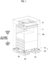
- Fig. 1 is a perspective view showing a state where a multifunction machine 100 is packed using a packing body 1 to which the present exemplary embodiment is applied.
- a box body 10 is shown by a broken line
- the multifunction machine 100 and a transportation pallet 20 are shown by solid lines.
- the transportation pallet 20 is an example of a packing body carrier.
- the multifunction machine 100 is covered with the box body 10 after placed on an upper surface of the transportation pallet 20.
- the multifunction machine 100 is provided with casters 101 as legs for supporting the multifunction machine 100, and the multifunction machine 100 is supported by the four casters 101.
- the box body 10 includes a square tubular side surface portion 11 that protects side surfaces of the multifunction machine 100 and a lid portion 12 that protects an upper surface of the multifunction machine 100.
- the side surface portion 11 of the box body 10 is configured to have a square tubular shape, and a lower end portion and an upper end portion thereof are open.
- the multifunction machine 100 in a state where the multifunction machine 100 is placed on the transportation pallet 20, the multifunction machine 100 is passed from an opening of a lower portion of the side surface portion 11 of the box body 10 to be wrapped up, and a lower end portion of the box body 10 is brought into contact with the transportation pallet 20 to place the box body 10.
- the box body 10 is formed of so-called cardboard.
- the cardboard is obtained by pasting thick paper to both sides of paper formed in a corrugated shape and is configured by a paper member.
- a material for the box body 10 is not limited thereto and may be formed of, for example, a resin material.
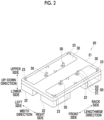
- Fig. 2 is a perspective view for describing the transportation pallet 20 according to the present exemplary embodiment.
- Fig. 3 is an exploded view for describing the inside of the transportation pallet 20. Fig. 3 is shown with only one of two plates 30 removed, and also a place hidden by the other plate 30 has the same structure.
- the transportation pallet 20 includes a body portion 21 that is a major structure of the transportation pallet 20, the plate 30 that receives a load from the casters 101 of the multifunction machine 100, and a restricting member 50 that restricts a movement of the multifunction machine 100 in a horizontal direction.
- the transportation pallet 20 of the present exemplary embodiment is formed of a resin material.
- the plate 30 is an example of a load receiving member. In the present exemplary embodiment, there is two plates 30, but the number of plates 30 is not limited, may be one, or may be three or more.
- the body portion 21 includes a foot 22 that is a base for supporting the transportation pallet 20, a contact unit 23 that positions the box body 10, a fixing portion 24 that fixes the plate 30 to the transportation pallet 20, a shock absorbing member 25 that absorbs a shock to the multifunction machine 100, and an accommodating portion 26 that accommodates the shock absorbing member 25.
- feet 22 are provided on a lower side of the body portion 21 and are provided on four sides of the transportation pallet 20.
- a plurality of provided feet 22 have a cavity through which a fork of a forklift passes.
- the contact unit 23 that positions the box body 10 is a protrusion provided at each of four corners of an upper surface of the body portion 21.
- the contact unit 23 is configured in a shape in which a long side of a right-angled triangle is recessed in a bow shape in a case of being viewed from a viewing direction in Fig. 2 , that is, the transportation pallet 20 is viewed from an upper side.
- four contact units 23 are disposed such that a rectangular region formed by linking a right-angled portion of each of the four contact units 23 is formed at a determined interval inside an outer shape of the transportation pallet 20.
- the rectangular region formed by linking the right-angled portion of each of the four contact units 23 corresponds to a region of an opening of the lower end portion of the box body 10.
- the fixing portion 24 that fixes the plate 30 to the transportation pallet 20 is provided in a central region of the transportation pallet 20 in a lengthwise direction of Fig. 3 , drops by a thickness D of the plate 30 from the lower side from the upper surface of the body portion 21, and forms a surface parallel to the upper surface of the body portion 21.
- the parallel surface is configured in a rectangular shape.
- the fixing portion 24 includes a protruding portion 28 that performs positioning with the plate 30 and a screw fixing portion 29 for tightening a screw which fixes the plate 30.
- the protruding portion 28 is, for example, a protrusion configured in a cylindrical shape.
- the protruding portion 28 is provided at, for example, a central region of the fixing portion 24 in the lengthwise direction of Fig. 3 , and a plurality of protruding portions 28, such as two, are arranged in a width direction.
- the screw fixing portions 29 are screw holes and are provided in, for example, four corners of the fixing portion 24 configured in a rectangular shape.
- the shock absorbing member 25 is provided below the plate 30 and gently supports the plate 30.
- the shock absorbing member 25 is made of, for example, a material having shock absorbing properties, such as a foamed resin material and a rubber material, and a plurality of (herein, two) shock absorbing members 25 are provided with respect to one plate 30 via the fixing portion 24 in the present exemplary embodiment.
- the shock absorbing member 25 has a substantially right-angled parallelepiped shape and is configured to have, for example, the same thickness as the thickness of the fixing portion 24. In Fig. 3 , the thickness is shown as a length L.
- the accommodating portion 26 that accommodates the shock absorbing member 25 is recessed in accordance with the shape of the shock absorbing member 25 and is formed in accordance with the number of shock absorbing members 25. As described above, since the shock absorbing member 25 is provided below the plate 30, the accommodating portion 26 is at a position of being covered with the plate 30, and one accommodating portion 26 is provided for each of a back side and a front side in the lengthwise direction with respect to the fixing portion 24 in the example shown in Fig. 3 . In addition, in the example shown in Fig.
- the accommodating portion 26 is recessed downward by a length of L in accordance with the thickness of the shock absorbing member 25 with the position of the fixing portion 24 as reference and is recessed from a surface of the body portion 21 by a length of D + L obtained by adding the thickness D of the plate 30.
- the plate 30 is a plate that has a shape of a rectangle extending in the lengthwise direction and of which four corners of the rectangle are rounded.
- the plate 30 is made of a material having elasticity with respect to plate bending deformation and is formed of, for example, a resin material.
- the plate 30 includes a positioning hole 31 that is a through-hole for performing positioning with the body portion 21, a fixing hole 32 that is a through-hole for fixing to the body portion 21, and a load receiving portion 35 that receives a load from the casters 101 (see Fig. 1 ) of the multifunction machine 100.
- the positioning hole 31 is removed such that the cylindrical shape of the protruding portion 28 of the fixing portion 24 is accommodated and is disposed in a central region in a longitudinal direction of the plate 30, and two positioning holes 31 are arranged in a lateral direction.
- the fixing hole 32 is a through-hole through which a screw passes and is provided corresponding to the screw fixing portion 29 of the fixing portion 24.
- the load receiving portions 35 are regions on both end sides from a region where the plate 30 is fixed to the body portion 21 and are regions that receive a load from the casters 101 of the multifunction machine 100. In other words, the plate 30 is fixed to the body portion 21 in a region between the load receiving portions 35.
- the restricting member 50 shown in Fig. 2 is a member for restricting a horizontal movement of the multifunction machine 100 (see Fig. 1 ) placed on the transportation pallet 20.
- the restricting member 50 is, for example, a plate member made of a sheet metal formed of high-tensile steel.
- the restricting member 50 is configured by, for example, an L-shaped leaf spring.
- the restricting member 50 includes a base portion 51 that is fixed to the load receiving portion 35 of the plate 30, an insertion portion 52 that is inserted from a gap in an exterior of a lower surface of the multifunction machine 100, and a hook portion 53 that is inserted from the exterior of the lower surface of the multifunction machine 100 and that is hooked to the inside of the multifunction machine 100.
- the base portion 51 is configured in, for example, a rectangular shape and has a through-hole for fixing the base portion 51 to the load receiving portion 35 of the plate 30 at a central portion of the rectangular shape. By passing a bolt through the through-hole and fixing the bolt to the load receiving portion 35 of the plate 30, the base portion 51 is fixed to the plate 30.
- the insertion portion 52 is a plate that extends from one side of the rectangle of the base portion 51 to be inserted into the gap in the exterior of the lower surface of the multifunction machine 100 and extends from the upper surface of the transportation pallet 20 toward the upper side.
- the hook portion 53 is hooked from the inside of the exterior of the lower surface of the multifunction machine 100 and restrains the multifunction machine 100 such that the restricting member 50 does not come off the multifunction machine 100 in a case where the multifunction machine 100 moves upward.
- the hook portion 53 bends from an upper portion of the insertion portion 52.
- a transportation pallet 200 that does not have the plate 30 and that restricts a horizontal movement of the multifunction machine 100 with a restricting member 500 which does not elastically deform will be described.
- Fig. 6 is a schematic view showing the comparative example in which the position of the restricting member 500 does not change with respect to the transportation pallet 200 and shows, in a case where the multifunction machine 100 has moved horizontally with respect to the transportation pallet 200, an example in a case where the horizontal movement is restricted by the restricting member 500.
- one end of the restricting member 500 fixed to the transportation pallet 200 enters a hole 111 provided in the lower portion of the multifunction machine 100, and the horizontal movement of the multifunction machine 100 is restricted.
- the multifunction machine 100 receives a high load in the rightward direction, but in this case, in a case where the restricting member 500 hits the hole 111 of the multifunction machine 100, the transportation pallet 200 cannot move in the rightward direction any further due to the stopped restricting member 500.
- the multifunction machine 100 rotates clockwise with a contact portion between the restricting member 500 and the hole 111 on a right side as reference. As a result, an upper end of the multifunction machine 100 is tilted, collides with the box body 10, and receives a locally great shock.
- a local shock generated at the multifunction machine 100 in which the upper end of the multifunction machine 100 shown in Fig. 6 is tilted and collides with the box body 10 is reduced.
- Fig. 4 is a schematic view showing a state where the multifunction machine 100 moves in the horizontal direction with respect to the transportation pallet 20 and has come into contact with the box body 10. A case where the transportation pallet 20, which has been moving in the rightward direction of Fig. 4 , is suddenly stopped is assumed.
- the restricting member 50 of the transportation pallet 20 of the present exemplary embodiment is provided at the plate 30 that has elasticity.
- a central region of the plate 30 in the longitudinal direction of the plate 30 is fixed, and the load receiving portions 35 (see Fig. 3 ) on both end sides of the plate 30 are not fixed and are placed on the shock absorbing members 25. For this reason, the load receiving portions 35 can rise and sink.
- the load receiving portions 35 rise with a weaker force from the central region in the longitudinal direction to which the plate 30 is fixed toward a tip.
- a plate surface of the plate 30 can rise in a twisted manner depending on the structure of the plate 30.
- a part of the plate 30 rises.
- the restricting member 50 can be tilted. Accordingly, the multifunction machine 100 horizontally moves without rotating around the restricting member 50.
- a side surface of the multifunction machine 100 which has horizontally moved collides with the box body 10.
- the side surface of the multifunction machine 100 collides with the box body 10 for example, as a wide region of the side surface, such as the entire side surface, collides, a shock can be dispersed, and generation of a locally great shock can be suppressed.
- Figs. 5A and 5B are enlarged views of a region V of Fig. 4 .
- Fig. 5A is a view showing a state where the multifunction machine 100 horizontally moves and starts to come into contact with the restricting member 50.
- Fig. 5B is a view showing a state where the multifunction machine 100 has further horizontally moved.
- the load receiving portion 35 (see Fig. 3 ) of the plate 30 is disposed on the shock absorbing member 25.
- the longitudinal direction of the plate 30 is disposed in a direction from the front side to the back side of Fig. 5A .
- the restricting member 50 is disposed such that a plate surface of the insertion portion 52 of the restricting member 50 faces a direction toward the front of Fig. 5A . That is, the restricting member 50 does not elastically deform even in a case where a force is applied to the insertion portion 52 from the left side to the right side in the width direction of Fig. 5A .
- the insertion portion 52 and the hole 111 come into contact with each other. Then, in a case where the multifunction machine 100 further moves to the right side in the width direction, the insertion portion 52 receives a force to the right side in the width direction.
- the plate 30 of the present exemplary embodiment has elasticity, and a part thereof rises in a case where a force to the right side in the width direction is generated at the insertion portion 52. Accordingly, the insertion portion 52 is tilted, a position where the insertion portion 52 and the hole 111 come into contact with each other moves in the rightward direction, and the multifunction machine 100 horizontally moves as it is.
- the multifunction machine 100 horizontally moves to the right side in the width direction (the lateral direction of the plate 30)
- the load receiving portion 35 of the plate 30 rises and is tilted also in a case where the multifunction machine 100 has horizontally moved in the longitudinal direction of the plate 30, the restricting member 50 is tilted, and the movement of the multifunction machine 100 is continued. Accordingly, by colliding with a wide region of a front surface or a back surface of the multifunction machine 100, a shock can be dispersed.
- the load receiving portion 35 of the plate 30 of the present exemplary embodiment is placed on the shock absorbing member 25, a shock in an up-down direction is absorbed by the shock absorbing member 25, and a shock to the multifunction machine 100 is suppressed.
- the packed body packed by the packing body 1 is not limited to the multifunction machine 100 and can also be, for example, an electronic device to be packed.
- a load received from the packed body can be dispersed.
- a rise in the longitudinal direction can be increased.
- a rise in the longitudinal direction can be increased.
Landscapes
- Engineering & Computer Science (AREA)
- Mechanical Engineering (AREA)
- Buffer Packaging (AREA)
- Packaging Of Machine Parts And Wound Products (AREA)
- Pallets (AREA)
Abstract
A packing body carrier (20) includes a body portion on which a packed body (100) is placed and a load receiving member (30) that is provided at the body portion and that has a load receiving portion which receives a load of the packed body, in which in a case where the packed body has horizontally moved, the load receiving portion (30) is inclined with respect to a horizontal plane.
Description
- The present invention relates to a packing body carrier and a packing body.
- In general, in order to reduce a shock in a case of transporting a product, various types of shock absorbing materials are used. The shock absorbing materials fill a gap between the product and a packing material such that the product does not move in the packing material which packs the product. In general, many of the shock absorbing materials are disposable and are not reused in many cases. In order to reduce the amount of disposable shock absorbing material, a shock absorbing member is provided at a reusable pallet in some cases.
- For example,
JP2007-69925A - For example,
JP2004-99150A - In a case where a shock absorbing material that fills a gap between a packing body and a packed body is not provided, a gap between a side surface of the packed body and an inner surface of the packing body is generated. For example, in a case where a force is applied to the packed body in a horizontal direction, the packed body is tilted and locally collides with the inner surface of the packing body in some cases.
- An object of the present invention is to suppress a local shock to the packed body.
- According to a first aspect of the present disclosure, there is provided a packing body carrier including a body portion on which a packed body is placed and a load receiving member that is provided at the body portion and that has a load receiving portion which receives a load of the packed body, in which in a case where the packed body has horizontally moved, the load receiving portion may be inclined with respect to a horizontal plane.
- According to a second aspect of the present disclosure, there is provided a packing body carrier including a body portion on which a packed body is placed and a load receiving member that is provided at the body portion and that has a load receiving portion which receives a load of the packed body, in which the load receiving member may be fixed to the body portion in a region between load receiving portions.
- According to a third aspect of the present disclosure, in the packing body carrier according to the first or second aspect, a restricting portion that has one end fixed to the load receiving member and that restricts the horizontal movement of the packed body by coming into contact with a part of the packed body in a case where the packed body has horizontally moved may be further included, and a part of the load receiving portion may rise in a case where the restricting portion receives a force in a horizontal direction.
- According to a fourth aspect of the present disclosure, in the packing body carrier according to any one of the first to third aspects, the load receiving member may be a member that extends in a longitudinal direction.
- According to a fifth aspect of the present disclosure, in the packing body carrier according to the fourth aspect, the body portion may support the load receiving member in a lateral direction intersecting the longitudinal direction.
- According to a sixth aspect of the present disclosure, in the packing body carrier according to the fifth aspect, the load receiving portion may rise as the restricting portion receives a force in the longitudinal direction compared to a case where the restricting portion receives a force in the lateral direction.
- According to a seventh aspect of the present disclosure, in the packing body carrier according to the first or second aspect, the body portion may include a shock absorbing member that comes into contact with the load receiving portion and that reduces a shock.
- According to an eighth aspect of the present disclosure, in the packing body carrier according to the seventh aspect, the shock absorbing member may be provided at a surface different from a surface of the load receiving portion, which receives the load of the packed body.
- According to a ninth aspect of the present disclosure, there is provided a packing body including a body portion on which a packed body is placed, a box body that covers the packed body, and a load receiving member that is provided at the body portion and that has a load receiving portion which receives a load of the packed body, in which in a case where the packed body has horizontally moved, the load receiving portion may be inclined with respect to a horizontal plane.
- In the first aspect of the present invention, a local shock to the packed body can be suppressed.
- In the second aspect of the present invention, a local shock to the packed body can be suppressed.
- In the third aspect of the present invention, it can be suppressed that the packed body is tilted with respect to the packing body.
- In the fourth aspect of the present invention, a load received from the packed body can be dispersed.
- In the fifth aspect of the present invention, a rise in the longitudinal direction can be increased.
- In the sixth aspect of the present invention, a rise in the longitudinal direction can be increased.
- In the seventh aspect of the present invention, a shock to the packed body can be reduced.
- In the eighth aspect of the present invention, a shock to the packed body can be reduced.
- In the ninth aspect of the present invention, a local shock to the packed body can be suppressed.
- Exemplary embodiment(s) of the present invention will be described in detail based on the following figures, wherein:
-
Fig. 1 is a perspective view showing a state where a multifunction machine is packed using a packing body to which the present exemplary embodiment is applied; -
Fig. 2 is a perspective view for describing a transportation pallet according to the present exemplary embodiment; -
Fig. 3 is an exploded view for describing an inside of the transportation pallet; -
Fig. 4 is a schematic view showing a state where the multifunction machine moves in a horizontal direction with respect to the transportation pallet and has come into contact with a box body; -
Figs. 5A and 5B are enlarged views of a region V ofFig. 4 ;Fig. 5A is a view showing a state where the multifunction machine horizontally moves and starts to come into contact with a restricting member, andFig. 5B is a view showing a state where the multifunction machine has further horizontally moved; and -
Fig. 6 is a schematic view showing a comparative example in which a position of the restricting member does not change with respect to the transportation pallet. - Hereinafter, an exemplary embodiment of the present invention will be described in detail with reference to the accompanying drawings.
-
Fig. 1 is a perspective view showing a state where amultifunction machine 100 is packed using apacking body 1 to which the present exemplary embodiment is applied. InFig. 1 , abox body 10 is shown by a broken line, and themultifunction machine 100 and atransportation pallet 20 are shown by solid lines. Thetransportation pallet 20 is an example of a packing body carrier. - As shown in
Fig. 1 , themultifunction machine 100 is covered with thebox body 10 after placed on an upper surface of thetransportation pallet 20. Themultifunction machine 100 is provided withcasters 101 as legs for supporting themultifunction machine 100, and themultifunction machine 100 is supported by the fourcasters 101. - The
box body 10 includes a square tubularside surface portion 11 that protects side surfaces of themultifunction machine 100 and alid portion 12 that protects an upper surface of themultifunction machine 100. Theside surface portion 11 of thebox body 10 is configured to have a square tubular shape, and a lower end portion and an upper end portion thereof are open. In a case of packing themultifunction machine 100, in a state where themultifunction machine 100 is placed on thetransportation pallet 20, themultifunction machine 100 is passed from an opening of a lower portion of theside surface portion 11 of thebox body 10 to be wrapped up, and a lower end portion of thebox body 10 is brought into contact with thetransportation pallet 20 to place thebox body 10. - An opening of the upper end portion of the
side surface portion 11 of thebox body 10 is closed by thelid portion 12, and themultifunction machine 100 is packed by thebox body 10. In the present exemplary embodiment, thebox body 10 is formed of so-called cardboard. The cardboard is obtained by pasting thick paper to both sides of paper formed in a corrugated shape and is configured by a paper member. A material for thebox body 10 is not limited thereto and may be formed of, for example, a resin material. - Next, the
transportation pallet 20 will be described with reference toFigs. 2 and3 . -
Fig. 2 is a perspective view for describing thetransportation pallet 20 according to the present exemplary embodiment. In addition,Fig. 3 is an exploded view for describing the inside of thetransportation pallet 20.Fig. 3 is shown with only one of twoplates 30 removed, and also a place hidden by theother plate 30 has the same structure. - As shown in
Fig. 2 , thetransportation pallet 20 includes abody portion 21 that is a major structure of thetransportation pallet 20, theplate 30 that receives a load from thecasters 101 of themultifunction machine 100, and a restrictingmember 50 that restricts a movement of themultifunction machine 100 in a horizontal direction. Thetransportation pallet 20 of the present exemplary embodiment is formed of a resin material. Theplate 30 is an example of a load receiving member. In the present exemplary embodiment, there is twoplates 30, but the number ofplates 30 is not limited, may be one, or may be three or more. - As shown in
Figs. 2 and3 , thebody portion 21 includes afoot 22 that is a base for supporting thetransportation pallet 20, acontact unit 23 that positions thebox body 10, afixing portion 24 that fixes theplate 30 to thetransportation pallet 20, ashock absorbing member 25 that absorbs a shock to themultifunction machine 100, and anaccommodating portion 26 that accommodates theshock absorbing member 25. - Four
feet 22 are provided on a lower side of thebody portion 21 and are provided on four sides of thetransportation pallet 20. In addition, a plurality of providedfeet 22 have a cavity through which a fork of a forklift passes. - The
contact unit 23 that positions thebox body 10 is a protrusion provided at each of four corners of an upper surface of thebody portion 21. Thecontact unit 23 is configured in a shape in which a long side of a right-angled triangle is recessed in a bow shape in a case of being viewed from a viewing direction inFig. 2 , that is, thetransportation pallet 20 is viewed from an upper side. In addition, fourcontact units 23 are disposed such that a rectangular region formed by linking a right-angled portion of each of the fourcontact units 23 is formed at a determined interval inside an outer shape of thetransportation pallet 20. In addition, the rectangular region formed by linking the right-angled portion of each of the fourcontact units 23 corresponds to a region of an opening of the lower end portion of thebox body 10. - The fixing
portion 24 that fixes theplate 30 to thetransportation pallet 20 is provided in a central region of thetransportation pallet 20 in a lengthwise direction ofFig. 3 , drops by a thickness D of theplate 30 from the lower side from the upper surface of thebody portion 21, and forms a surface parallel to the upper surface of thebody portion 21. The parallel surface is configured in a rectangular shape. - The fixing
portion 24 includes a protrudingportion 28 that performs positioning with theplate 30 and ascrew fixing portion 29 for tightening a screw which fixes theplate 30. The protrudingportion 28 is, for example, a protrusion configured in a cylindrical shape. The protrudingportion 28 is provided at, for example, a central region of the fixingportion 24 in the lengthwise direction ofFig. 3 , and a plurality of protrudingportions 28, such as two, are arranged in a width direction. Thescrew fixing portions 29 are screw holes and are provided in, for example, four corners of the fixingportion 24 configured in a rectangular shape. - The
shock absorbing member 25 is provided below theplate 30 and gently supports theplate 30. Theshock absorbing member 25 is made of, for example, a material having shock absorbing properties, such as a foamed resin material and a rubber material, and a plurality of (herein, two)shock absorbing members 25 are provided with respect to oneplate 30 via the fixingportion 24 in the present exemplary embodiment. Theshock absorbing member 25 has a substantially right-angled parallelepiped shape and is configured to have, for example, the same thickness as the thickness of the fixingportion 24. InFig. 3 , the thickness is shown as a length L. - The
accommodating portion 26 that accommodates theshock absorbing member 25 is recessed in accordance with the shape of theshock absorbing member 25 and is formed in accordance with the number ofshock absorbing members 25. As described above, since theshock absorbing member 25 is provided below theplate 30, theaccommodating portion 26 is at a position of being covered with theplate 30, and one accommodatingportion 26 is provided for each of a back side and a front side in the lengthwise direction with respect to the fixingportion 24 in the example shown inFig. 3 . In addition, in the example shown inFig. 3 , theaccommodating portion 26 is recessed downward by a length of L in accordance with the thickness of theshock absorbing member 25 with the position of the fixingportion 24 as reference and is recessed from a surface of thebody portion 21 by a length of D + L obtained by adding the thickness D of theplate 30. - In a case of being viewed from the upper side of
Fig. 2 , theplate 30 is a plate that has a shape of a rectangle extending in the lengthwise direction and of which four corners of the rectangle are rounded. Theplate 30 is made of a material having elasticity with respect to plate bending deformation and is formed of, for example, a resin material. - The
plate 30 includes a positioning hole 31 that is a through-hole for performing positioning with thebody portion 21, a fixing hole 32 that is a through-hole for fixing to thebody portion 21, and aload receiving portion 35 that receives a load from the casters 101 (seeFig. 1 ) of themultifunction machine 100. The positioning hole 31 is removed such that the cylindrical shape of the protrudingportion 28 of the fixingportion 24 is accommodated and is disposed in a central region in a longitudinal direction of theplate 30, and two positioning holes 31 are arranged in a lateral direction. - The fixing hole 32 is a through-hole through which a screw passes and is provided corresponding to the
screw fixing portion 29 of the fixingportion 24. - The
load receiving portions 35 are regions on both end sides from a region where theplate 30 is fixed to thebody portion 21 and are regions that receive a load from thecasters 101 of themultifunction machine 100. In other words, theplate 30 is fixed to thebody portion 21 in a region between theload receiving portions 35. - The restricting
member 50 shown inFig. 2 is a member for restricting a horizontal movement of the multifunction machine 100 (seeFig. 1 ) placed on thetransportation pallet 20. The restrictingmember 50 is, for example, a plate member made of a sheet metal formed of high-tensile steel. The restrictingmember 50 is configured by, for example, an L-shaped leaf spring. The restrictingmember 50 includes abase portion 51 that is fixed to theload receiving portion 35 of theplate 30, aninsertion portion 52 that is inserted from a gap in an exterior of a lower surface of themultifunction machine 100, and ahook portion 53 that is inserted from the exterior of the lower surface of themultifunction machine 100 and that is hooked to the inside of themultifunction machine 100. - The
base portion 51 is configured in, for example, a rectangular shape and has a through-hole for fixing thebase portion 51 to theload receiving portion 35 of theplate 30 at a central portion of the rectangular shape. By passing a bolt through the through-hole and fixing the bolt to theload receiving portion 35 of theplate 30, thebase portion 51 is fixed to theplate 30. - In a case where the
multifunction machine 100 is placed on thetransportation pallet 20, theinsertion portion 52 is a plate that extends from one side of the rectangle of thebase portion 51 to be inserted into the gap in the exterior of the lower surface of themultifunction machine 100 and extends from the upper surface of thetransportation pallet 20 toward the upper side. - The
hook portion 53 is hooked from the inside of the exterior of the lower surface of themultifunction machine 100 and restrains themultifunction machine 100 such that the restrictingmember 50 does not come off themultifunction machine 100 in a case where themultifunction machine 100 moves upward. In the present exemplary embodiment, thehook portion 53 bends from an upper portion of theinsertion portion 52. - Herein, in order to facilitate understanding of features of the present exemplary embodiment, a comparative example will be given and described.
- As the comparative example, a
transportation pallet 200 that does not have theplate 30 and that restricts a horizontal movement of themultifunction machine 100 with a restrictingmember 500 which does not elastically deform will be described. -
Fig. 6 is a schematic view showing the comparative example in which the position of the restrictingmember 500 does not change with respect to thetransportation pallet 200 and shows, in a case where themultifunction machine 100 has moved horizontally with respect to thetransportation pallet 200, an example in a case where the horizontal movement is restricted by the restrictingmember 500. - As shown in
Fig. 6 , one end of the restrictingmember 500 fixed to thetransportation pallet 200 enters ahole 111 provided in the lower portion of themultifunction machine 100, and the horizontal movement of themultifunction machine 100 is restricted. However, for example, in a case where thetransportation pallet 200 which has been moving in a rightward direction ofFig. 6 suddenly stops, themultifunction machine 100 receives a high load in the rightward direction, but in this case, in a case where the restrictingmember 500 hits thehole 111 of themultifunction machine 100, thetransportation pallet 200 cannot move in the rightward direction any further due to the stopped restrictingmember 500. For this reason, themultifunction machine 100 rotates clockwise with a contact portion between the restrictingmember 500 and thehole 111 on a right side as reference. As a result, an upper end of themultifunction machine 100 is tilted, collides with thebox body 10, and receives a locally great shock. - In the present exemplary embodiment, a local shock generated at the
multifunction machine 100 in which the upper end of themultifunction machine 100 shown inFig. 6 is tilted and collides with thebox body 10 is reduced. - Next, a movement in a case where the
multifunction machine 100 has horizontally moved in thetransportation pallet 20 of the present exemplary embodiment will be described with reference toFigs. 4 to 5B . -
Fig. 4 is a schematic view showing a state where themultifunction machine 100 moves in the horizontal direction with respect to thetransportation pallet 20 and has come into contact with thebox body 10. A case where thetransportation pallet 20, which has been moving in the rightward direction ofFig. 4 , is suddenly stopped is assumed. - The restricting
member 50 of thetransportation pallet 20 of the present exemplary embodiment is provided at theplate 30 that has elasticity. As described above, a central region of theplate 30 in the longitudinal direction of theplate 30 is fixed, and the load receiving portions 35 (seeFig. 3 ) on both end sides of theplate 30 are not fixed and are placed on theshock absorbing members 25. For this reason, theload receiving portions 35 can rise and sink. Theload receiving portions 35 rise with a weaker force from the central region in the longitudinal direction to which theplate 30 is fixed toward a tip. In addition, a plate surface of theplate 30 can rise in a twisted manner depending on the structure of theplate 30. - As shown in
Fig. 4 , in a case where themultifunction machine 100 moves right and left in the width direction, a part of theplate 30 rises. As theplate 30 rises, the restrictingmember 50 can be tilted. Accordingly, themultifunction machine 100 horizontally moves without rotating around the restrictingmember 50. A side surface of themultifunction machine 100 which has horizontally moved collides with thebox body 10. As the side surface of themultifunction machine 100 collides with thebox body 10, for example, as a wide region of the side surface, such as the entire side surface, collides, a shock can be dispersed, and generation of a locally great shock can be suppressed. - Herein, a movement until the
multifunction machine 100 moves from a left side to the right side in the width direction and the state ofFig. 4 is reached will be described with reference toFigs. 5A and 5B . -
Figs. 5A and 5B are enlarged views of a region V ofFig. 4 .Fig. 5A is a view showing a state where themultifunction machine 100 horizontally moves and starts to come into contact with the restrictingmember 50. In addition,Fig. 5B is a view showing a state where themultifunction machine 100 has further horizontally moved. - As shown in
Fig. 5A , the load receiving portion 35 (seeFig. 3 ) of theplate 30 is disposed on theshock absorbing member 25. In addition, the longitudinal direction of theplate 30 is disposed in a direction from the front side to the back side ofFig. 5A . The restrictingmember 50 is disposed such that a plate surface of theinsertion portion 52 of the restrictingmember 50 faces a direction toward the front ofFig. 5A . That is, the restrictingmember 50 does not elastically deform even in a case where a force is applied to theinsertion portion 52 from the left side to the right side in the width direction ofFig. 5A . - In a case where the
multifunction machine 100 moves from the left side to the right side in the width direction with respect to thetransportation pallet 20, theinsertion portion 52 and thehole 111 come into contact with each other. Then, in a case where themultifunction machine 100 further moves to the right side in the width direction, theinsertion portion 52 receives a force to the right side in the width direction. Theplate 30 of the present exemplary embodiment has elasticity, and a part thereof rises in a case where a force to the right side in the width direction is generated at theinsertion portion 52. Accordingly, theinsertion portion 52 is tilted, a position where theinsertion portion 52 and thehole 111 come into contact with each other moves in the rightward direction, and themultifunction machine 100 horizontally moves as it is. - In addition, even in a case where the
multifunction machine 100 does not rotate around the restrictingmember 50, for example, a case where a frictional force between thecasters 101 and theplate 30 is great, rotation around thecasters 101 is performed in some cases. - In the present exemplary embodiment, as shown in
Fig. 5B , as theload receiving portion 35 of theplate 30 is tilted to move downward in a movement direction of the multifunction machine 100 (downward to the right), an increase in the frictional force between thecasters 101 and theplate 30 can be suppressed, and the occurrence of rotation around thecasters 101 is suppressed. Accordingly, themultifunction machine 100 continues to horizontally move. - In addition, although an example in which the
multifunction machine 100 horizontally moves to the right side in the width direction (the lateral direction of the plate 30) has been described with reference toFig. 4 , as theload receiving portion 35 of theplate 30 rises and is tilted also in a case where themultifunction machine 100 has horizontally moved in the longitudinal direction of theplate 30, the restrictingmember 50 is tilted, and the movement of themultifunction machine 100 is continued. Accordingly, by colliding with a wide region of a front surface or a back surface of themultifunction machine 100, a shock can be dispersed. - In addition, the
load receiving portion 35 of theplate 30 of the present exemplary embodiment is placed on theshock absorbing member 25, a shock in an up-down direction is absorbed by theshock absorbing member 25, and a shock to themultifunction machine 100 is suppressed. - Although the
multifunction machine 100 has been described hereinbefore as an example of a packed body in the exemplary embodiment of the present invention, the packed body packed by the packingbody 1 is not limited to themultifunction machine 100 and can also be, for example, an electronic device to be packed. -
- (((1))) A packing body carrier comprising:
- a body portion on which a packed body is placed; and
- a load receiving member that is provided at the body portion and that has a load receiving portion which receives a load of the packed body,
- wherein in a case where the packed body has horizontally moved, the load receiving portion is inclined with respect to a horizontal plane.
- (((2))) A packing body carrier comprising:
- a body portion on which a packed body is placed; and
- a load receiving member that is provided at the body portion and that has a load receiving portion which receives a load of the packed body,
- wherein the load receiving member is fixed to the body portion in a region between load receiving portions.
- (((3))) The packing body carrier according to (((1))) or (((2))), further comprising:
- a restricting portion that has one end fixed to the load receiving member and that restricts the horizontal movement of the packed body by coming into contact with a part of the packed body in a case where the packed body has horizontally moved,
- wherein a part of the load receiving portion rises in a case where the restricting portion receives a force in a horizontal direction.
- (((4))) The packing body carrier according to any one of (((1))) to (((3))),
wherein the load receiving member is a member that extends in a longitudinal direction. - (((5))) The packing body carrier according to (((4))),
wherein the body portion supports the load receiving member in a lateral direction intersecting the longitudinal direction. - (((6))) The packing body carrier according to (((5))),
wherein the load receiving portion rises as the restricting portion receives a force in the longitudinal direction compared to a case where the restricting portion receives a force in the lateral direction. - (((7))) The packing body carrier according to (((1))) or (((2))),
wherein the body portion includes a shock absorbing member that comes into contact with the load receiving portion and that reduces a shock. - (((8))) The packing body carrier according to (((7))),
wherein the shock absorbing member is provided at a surface different from a surface of the load receiving portion, which receives the load of the packed body. - (((9)))
A packing body comprising:- a body portion on which a packed body is placed;
- a box body that covers the packed body; and
- a load receiving member that is provided at the body portion and that has a load receiving portion which receives a load of the packed body,
- wherein in a case where the packed body has horizontally moved, the load receiving portion is inclined with respect to a horizontal plane.
- In the packing body carrier according to (((1))), a local shock to the packed body can be suppressed.
- In the packing body carrier according to (((2))), a local shock to the packed body can be suppressed.
- In the packing body carrier according to (((3))), it can be suppressed that the packed body is tilted with respect to the packing body.
- In the packing body carrier according to (((4))), a load received from the packed body can be dispersed.
- In the packing body carrier according to (((5))), a rise in the longitudinal direction can be increased.
- In the packing body carrier according to (((6))), a rise in the longitudinal direction can be increased.
- In the packing body carrier according to (((7))), a shock to the packed body can be reduced.
- In the packing body carrier according to (((8))), a shock to the packed body can be reduced.
- In the packing body according to (((9))), a local shock to the packed body can be suppressed.
- The foregoing description of the exemplary embodiments of the present invention has been provided for the purposes of illustration and description. It is not intended to be exhaustive or to limit the invention to the precise forms disclosed. Obviously, many modifications and variations will be apparent to practitioners skilled in the art. The embodiments were chosen and described in order to best explain the principles of the invention and its practical applications, thereby enabling others skilled in the art to understand the invention for various embodiments and with the various modifications as are suited to the particular use contemplated. It is intended that the scope of the invention be defined by the following claims and their equivalents.
-
- 1: packing body
- 10: box body
- 20: transportation pallet
- 21: body portion
- 22: foot
- 24: fixing portion
- 25: shock absorbing member
- 26: accommodating portion
- 29: screw fixing portion
- 30: plate
- 32: fixing hole
- 35: load receiving portion
- 50: restricting member
- 100: multifunction machine
- 101: caster
- 111: hole
Claims (9)
- A packing body carrier comprising:a body portion on which a packed body is placed; anda load receiving member that is provided at the body portion and that has a load receiving portion which receives a load of the packed body,wherein in a case where the packed body has horizontally moved, the load receiving portion is inclined with respect to a horizontal plane.
- A packing body carrier comprising:a body portion on which a packed body is placed; anda load receiving member that is provided at the body portion and that has a load receiving portion which receives a load of the packed body,wherein the load receiving member is fixed to the body portion in a region between load receiving portions.
- The packing body carrier according to claim 1 or 2, further comprising:a restricting portion that has one end fixed to the load receiving member and that restricts the horizontal movement of the packed body by coming into contact with a part of the packed body in a case where the packed body has horizontally moved,wherein a part of the load receiving portion rises in a case where the restricting portion receives a force in a horizontal direction.
- The packing body carrier according to any one of claims 1 to 3,
wherein the load receiving member is a member that extends in a longitudinal direction. - The packing body carrier according to claim 4,
wherein the body portion supports the load receiving member in a lateral direction intersecting the longitudinal direction. - The packing body carrier according to claim 5,
wherein the load receiving portion rises as the restricting portion receives a force in the longitudinal direction compared to a case where the restricting portion receives a force in the lateral direction. - The packing body carrier according to claim 1 or 2,
wherein the body portion includes a shock absorbing member that comes into contact with the load receiving portion and that reduces a shock. - The packing body carrier according to claim 7,
wherein the shock absorbing member is provided at a surface different from a surface of the load receiving portion, which receives the load of the packed body. - A packing body comprising:a body portion on which a packed body is placed;a box body that covers the packed body; anda load receiving member that is provided at the body portion and that has a load receiving portion which receives a load of the packed body,wherein in a case where the packed body has horizontally moved, the load receiving portion is inclined with respect to a horizontal plane.
Applications Claiming Priority (1)
| Application Number | Priority Date | Filing Date | Title |
|---|---|---|---|
| JP2023054420A JP2024142284A (en) | 2023-03-29 | 2023-03-29 | Packaging stacks and packages |
Publications (1)
| Publication Number | Publication Date |
|---|---|
| EP4438513A1 true EP4438513A1 (en) | 2024-10-02 |
Family
ID=87426749
Family Applications (1)
| Application Number | Title | Priority Date | Filing Date |
|---|---|---|---|
| EP23186669.0A Pending EP4438513A1 (en) | 2023-03-29 | 2023-07-20 | Packing body carrier and packing body |
Country Status (4)
| Country | Link |
|---|---|
| US (1) | US20240327105A1 (en) |
| EP (1) | EP4438513A1 (en) |
| JP (1) | JP2024142284A (en) |
| CN (1) | CN118723282A (en) |
Citations (9)
| Publication number | Priority date | Publication date | Assignee | Title |
|---|---|---|---|---|
| JPH0565890U (en) * | 1992-02-14 | 1993-08-31 | 株式会社富士通ゼネラル | Air conditioner fixing device |
| JP2004099150A (en) | 2002-09-12 | 2004-04-02 | Ricoh Co Ltd | Goods carrier |
| US20050150194A1 (en) * | 2003-12-24 | 2005-07-14 | Matsushita Electric Industrial Co., Ltd | Carrier apparatus |
| JP2005219790A (en) * | 2004-02-06 | 2005-08-18 | Daihatsu Motor Co Ltd | Transferring pallet for automobile part |
| JP2007069925A (en) | 2005-09-05 | 2007-03-22 | Ricoh Co Ltd | Packing equipment |
| JP2015205704A (en) * | 2014-04-18 | 2015-11-19 | ホシザキ電機株式会社 | Packing structure of packaged products |
| WO2020217483A1 (en) * | 2019-04-26 | 2020-10-29 | 三菱電機株式会社 | Packaging device for air conditioning machine |
| US20220306339A1 (en) * | 2021-03-23 | 2022-09-29 | Fujifilm Business Innovation Corp. | Packing body |
| US20220348378A1 (en) * | 2021-04-30 | 2022-11-03 | Fujifilm Business Innovation Corp. | Package unit |
-
2023
- 2023-03-29 JP JP2023054420A patent/JP2024142284A/en active Pending
- 2023-07-20 EP EP23186669.0A patent/EP4438513A1/en active Pending
- 2023-07-20 US US18/356,190 patent/US20240327105A1/en active Pending
- 2023-07-25 CN CN202310912320.3A patent/CN118723282A/en active Pending
Patent Citations (9)
| Publication number | Priority date | Publication date | Assignee | Title |
|---|---|---|---|---|
| JPH0565890U (en) * | 1992-02-14 | 1993-08-31 | 株式会社富士通ゼネラル | Air conditioner fixing device |
| JP2004099150A (en) | 2002-09-12 | 2004-04-02 | Ricoh Co Ltd | Goods carrier |
| US20050150194A1 (en) * | 2003-12-24 | 2005-07-14 | Matsushita Electric Industrial Co., Ltd | Carrier apparatus |
| JP2005219790A (en) * | 2004-02-06 | 2005-08-18 | Daihatsu Motor Co Ltd | Transferring pallet for automobile part |
| JP2007069925A (en) | 2005-09-05 | 2007-03-22 | Ricoh Co Ltd | Packing equipment |
| JP2015205704A (en) * | 2014-04-18 | 2015-11-19 | ホシザキ電機株式会社 | Packing structure of packaged products |
| WO2020217483A1 (en) * | 2019-04-26 | 2020-10-29 | 三菱電機株式会社 | Packaging device for air conditioning machine |
| US20220306339A1 (en) * | 2021-03-23 | 2022-09-29 | Fujifilm Business Innovation Corp. | Packing body |
| US20220348378A1 (en) * | 2021-04-30 | 2022-11-03 | Fujifilm Business Innovation Corp. | Package unit |
Also Published As
| Publication number | Publication date |
|---|---|
| CN118723282A (en) | 2024-10-01 |
| US20240327105A1 (en) | 2024-10-03 |
| JP2024142284A (en) | 2024-10-10 |
Similar Documents
| Publication | Publication Date | Title |
|---|---|---|
| JP5227827B2 (en) | Glass substrate container | |
| JP2003231569A (en) | Structure of package | |
| JP2006021800A (en) | Plate packing tool | |
| US10370169B2 (en) | Packing device | |
| US20240327105A1 (en) | Packing body carrier and packing body | |
| JP2010254370A (en) | Positioning plate and packaging device for electrical equipment using the same | |
| EP2996949B1 (en) | Shipping container and spring lock therefor | |
| JP2017218187A (en) | Buffer material, packing material, and packing body | |
| JP3210742U (en) | Glass plate package | |
| JP2015009885A (en) | Packaging material for resin film roll | |
| WO2019082298A1 (en) | Display panel packing tray and packing tray layered body | |
| JP2008179395A (en) | Pallet | |
| JP2006016008A (en) | Pallet for packing | |
| JP2004142783A (en) | Goods transporter | |
| CN115108178B (en) | Bale body | |
| JP4593574B2 (en) | Power semiconductor device packaging equipment | |
| JP5096209B2 (en) | Plate-like body transport box | |
| KR101574610B1 (en) | cover for packing boxes | |
| US6695140B2 (en) | Packaging method and protective packaging system with automatic positioning component | |
| JP2010116175A (en) | Packing tool | |
| JP3783179B2 (en) | Packing base | |
| CN218172921U (en) | Buffer structure, packing box and paperboard structure | |
| JP7135459B2 (en) | Buffer member for electronic component storage box and package structure using the same | |
| JP2008296961A (en) | Shock absorbing material | |
| JP3206163U (en) | Packing box |
Legal Events
| Date | Code | Title | Description |
|---|---|---|---|
| PUAI | Public reference made under article 153(3) epc to a published international application that has entered the european phase |
Free format text: ORIGINAL CODE: 0009012 |
|
| STAA | Information on the status of an ep patent application or granted ep patent |
Free format text: STATUS: THE APPLICATION HAS BEEN PUBLISHED |
|
| AK | Designated contracting states |
Kind code of ref document: A1 Designated state(s): AL AT BE BG CH CY CZ DE DK EE ES FI FR GB GR HR HU IE IS IT LI LT LU LV MC ME MK MT NL NO PL PT RO RS SE SI SK SM TR |
|
| STAA | Information on the status of an ep patent application or granted ep patent |
Free format text: STATUS: REQUEST FOR EXAMINATION WAS MADE |
|
| 17P | Request for examination filed |
Effective date: 20250114 |