EP4438493A1 - Hydrogen supply unit for an aircraft, method of supplying liquid hydrogen in an aircraft, and aircraft - Google Patents
Hydrogen supply unit for an aircraft, method of supplying liquid hydrogen in an aircraft, and aircraft Download PDFInfo
- Publication number
- EP4438493A1 EP4438493A1 EP23166095.2A EP23166095A EP4438493A1 EP 4438493 A1 EP4438493 A1 EP 4438493A1 EP 23166095 A EP23166095 A EP 23166095A EP 4438493 A1 EP4438493 A1 EP 4438493A1
- Authority
- EP
- European Patent Office
- Prior art keywords
- tank
- aircraft
- extraction chamber
- extraction
- hydrogen
- Prior art date
- Legal status (The legal status is an assumption and is not a legal conclusion. Google has not performed a legal analysis and makes no representation as to the accuracy of the status listed.)
- Granted
Links
Images

Classifications
-
- F—MECHANICAL ENGINEERING; LIGHTING; HEATING; WEAPONS; BLASTING
- F17—STORING OR DISTRIBUTING GASES OR LIQUIDS
- F17C—VESSELS FOR CONTAINING OR STORING COMPRESSED, LIQUEFIED OR SOLIDIFIED GASES; FIXED-CAPACITY GAS-HOLDERS; FILLING VESSELS WITH, OR DISCHARGING FROM VESSELS, COMPRESSED, LIQUEFIED, OR SOLIDIFIED GASES
- F17C9/00—Methods or apparatus for discharging liquefied or solidified gases from vessels not under pressure
-
- B—PERFORMING OPERATIONS; TRANSPORTING
- B64—AIRCRAFT; AVIATION; COSMONAUTICS
- B64D—EQUIPMENT FOR FITTING IN OR TO AIRCRAFT; FLIGHT SUITS; PARACHUTES; ARRANGEMENT OR MOUNTING OF POWER PLANTS OR PROPULSION TRANSMISSIONS IN AIRCRAFT
- B64D37/00—Arrangements in connection with fuel supply for power plant
- B64D37/30—Fuel systems for specific fuels
-
- B—PERFORMING OPERATIONS; TRANSPORTING
- B64—AIRCRAFT; AVIATION; COSMONAUTICS
- B64D—EQUIPMENT FOR FITTING IN OR TO AIRCRAFT; FLIGHT SUITS; PARACHUTES; ARRANGEMENT OR MOUNTING OF POWER PLANTS OR PROPULSION TRANSMISSIONS IN AIRCRAFT
- B64D37/00—Arrangements in connection with fuel supply for power plant
- B64D37/02—Tanks
- B64D37/06—Constructional adaptations thereof
- B64D37/08—Internal partitioning
-
- B—PERFORMING OPERATIONS; TRANSPORTING
- B64—AIRCRAFT; AVIATION; COSMONAUTICS
- B64D—EQUIPMENT FOR FITTING IN OR TO AIRCRAFT; FLIGHT SUITS; PARACHUTES; ARRANGEMENT OR MOUNTING OF POWER PLANTS OR PROPULSION TRANSMISSIONS IN AIRCRAFT
- B64D37/00—Arrangements in connection with fuel supply for power plant
- B64D37/02—Tanks
- B64D37/14—Filling or emptying
- B64D37/20—Emptying systems
-
- F—MECHANICAL ENGINEERING; LIGHTING; HEATING; WEAPONS; BLASTING
- F17—STORING OR DISTRIBUTING GASES OR LIQUIDS
- F17C—VESSELS FOR CONTAINING OR STORING COMPRESSED, LIQUEFIED OR SOLIDIFIED GASES; FIXED-CAPACITY GAS-HOLDERS; FILLING VESSELS WITH, OR DISCHARGING FROM VESSELS, COMPRESSED, LIQUEFIED, OR SOLIDIFIED GASES
- F17C13/00—Details of vessels or of the filling or discharging of vessels
-
- F—MECHANICAL ENGINEERING; LIGHTING; HEATING; WEAPONS; BLASTING
- F17—STORING OR DISTRIBUTING GASES OR LIQUIDS
- F17C—VESSELS FOR CONTAINING OR STORING COMPRESSED, LIQUEFIED OR SOLIDIFIED GASES; FIXED-CAPACITY GAS-HOLDERS; FILLING VESSELS WITH, OR DISCHARGING FROM VESSELS, COMPRESSED, LIQUEFIED, OR SOLIDIFIED GASES
- F17C3/00—Vessels not under pressure
-
- F—MECHANICAL ENGINEERING; LIGHTING; HEATING; WEAPONS; BLASTING
- F17—STORING OR DISTRIBUTING GASES OR LIQUIDS
- F17C—VESSELS FOR CONTAINING OR STORING COMPRESSED, LIQUEFIED OR SOLIDIFIED GASES; FIXED-CAPACITY GAS-HOLDERS; FILLING VESSELS WITH, OR DISCHARGING FROM VESSELS, COMPRESSED, LIQUEFIED, OR SOLIDIFIED GASES
- F17C7/00—Methods or apparatus for discharging liquefied, solidified, or compressed gases from pressure vessels, not covered by another subclass
- F17C7/02—Discharging liquefied gases
-
- F—MECHANICAL ENGINEERING; LIGHTING; HEATING; WEAPONS; BLASTING
- F17—STORING OR DISTRIBUTING GASES OR LIQUIDS
- F17C—VESSELS FOR CONTAINING OR STORING COMPRESSED, LIQUEFIED OR SOLIDIFIED GASES; FIXED-CAPACITY GAS-HOLDERS; FILLING VESSELS WITH, OR DISCHARGING FROM VESSELS, COMPRESSED, LIQUEFIED, OR SOLIDIFIED GASES
- F17C2201/00—Vessel construction, in particular geometry, arrangement or size
- F17C2201/03—Orientation
- F17C2201/035—Orientation with substantially horizontal main axis
-
- F—MECHANICAL ENGINEERING; LIGHTING; HEATING; WEAPONS; BLASTING
- F17—STORING OR DISTRIBUTING GASES OR LIQUIDS
- F17C—VESSELS FOR CONTAINING OR STORING COMPRESSED, LIQUEFIED OR SOLIDIFIED GASES; FIXED-CAPACITY GAS-HOLDERS; FILLING VESSELS WITH, OR DISCHARGING FROM VESSELS, COMPRESSED, LIQUEFIED, OR SOLIDIFIED GASES
- F17C2201/00—Vessel construction, in particular geometry, arrangement or size
- F17C2201/05—Size
- F17C2201/054—Size medium (>1 m3)
-
- F—MECHANICAL ENGINEERING; LIGHTING; HEATING; WEAPONS; BLASTING
- F17—STORING OR DISTRIBUTING GASES OR LIQUIDS
- F17C—VESSELS FOR CONTAINING OR STORING COMPRESSED, LIQUEFIED OR SOLIDIFIED GASES; FIXED-CAPACITY GAS-HOLDERS; FILLING VESSELS WITH, OR DISCHARGING FROM VESSELS, COMPRESSED, LIQUEFIED, OR SOLIDIFIED GASES
- F17C2203/00—Vessel construction, in particular walls or details thereof
- F17C2203/03—Thermal insulations
- F17C2203/0304—Thermal insulations by solid means
- F17C2203/0308—Radiation shield
- F17C2203/032—Multi-sheet layers
-
- F—MECHANICAL ENGINEERING; LIGHTING; HEATING; WEAPONS; BLASTING
- F17—STORING OR DISTRIBUTING GASES OR LIQUIDS
- F17C—VESSELS FOR CONTAINING OR STORING COMPRESSED, LIQUEFIED OR SOLIDIFIED GASES; FIXED-CAPACITY GAS-HOLDERS; FILLING VESSELS WITH, OR DISCHARGING FROM VESSELS, COMPRESSED, LIQUEFIED, OR SOLIDIFIED GASES
- F17C2203/00—Vessel construction, in particular walls or details thereof
- F17C2203/03—Thermal insulations
- F17C2203/0391—Thermal insulations by vacuum
-
- F—MECHANICAL ENGINEERING; LIGHTING; HEATING; WEAPONS; BLASTING
- F17—STORING OR DISTRIBUTING GASES OR LIQUIDS
- F17C—VESSELS FOR CONTAINING OR STORING COMPRESSED, LIQUEFIED OR SOLIDIFIED GASES; FIXED-CAPACITY GAS-HOLDERS; FILLING VESSELS WITH, OR DISCHARGING FROM VESSELS, COMPRESSED, LIQUEFIED, OR SOLIDIFIED GASES
- F17C2203/00—Vessel construction, in particular walls or details thereof
- F17C2203/06—Materials for walls or layers thereof; Properties or structures of walls or their materials
- F17C2203/0602—Wall structures; Special features thereof
- F17C2203/0612—Wall structures
- F17C2203/0626—Multiple walls
- F17C2203/0629—Two walls
-
- F—MECHANICAL ENGINEERING; LIGHTING; HEATING; WEAPONS; BLASTING
- F17—STORING OR DISTRIBUTING GASES OR LIQUIDS
- F17C—VESSELS FOR CONTAINING OR STORING COMPRESSED, LIQUEFIED OR SOLIDIFIED GASES; FIXED-CAPACITY GAS-HOLDERS; FILLING VESSELS WITH, OR DISCHARGING FROM VESSELS, COMPRESSED, LIQUEFIED, OR SOLIDIFIED GASES
- F17C2205/00—Vessel construction, in particular mounting arrangements, attachments or identifications means
- F17C2205/03—Fluid connections, filters, valves, closure means or other attachments
- F17C2205/0302—Fittings, valves, filters, or components in connection with the gas storage device
- F17C2205/0323—Valves
- F17C2205/0326—Valves electrically actuated
-
- F—MECHANICAL ENGINEERING; LIGHTING; HEATING; WEAPONS; BLASTING
- F17—STORING OR DISTRIBUTING GASES OR LIQUIDS
- F17C—VESSELS FOR CONTAINING OR STORING COMPRESSED, LIQUEFIED OR SOLIDIFIED GASES; FIXED-CAPACITY GAS-HOLDERS; FILLING VESSELS WITH, OR DISCHARGING FROM VESSELS, COMPRESSED, LIQUEFIED, OR SOLIDIFIED GASES
- F17C2221/00—Handled fluid, in particular type of fluid
- F17C2221/01—Pure fluids
- F17C2221/012—Hydrogen
-
- F—MECHANICAL ENGINEERING; LIGHTING; HEATING; WEAPONS; BLASTING
- F17—STORING OR DISTRIBUTING GASES OR LIQUIDS
- F17C—VESSELS FOR CONTAINING OR STORING COMPRESSED, LIQUEFIED OR SOLIDIFIED GASES; FIXED-CAPACITY GAS-HOLDERS; FILLING VESSELS WITH, OR DISCHARGING FROM VESSELS, COMPRESSED, LIQUEFIED, OR SOLIDIFIED GASES
- F17C2223/00—Handled fluid before transfer, i.e. state of fluid when stored in the vessel or before transfer from the vessel
- F17C2223/01—Handled fluid before transfer, i.e. state of fluid when stored in the vessel or before transfer from the vessel characterised by the phase
- F17C2223/0107—Single phase
- F17C2223/013—Single phase liquid
-
- F—MECHANICAL ENGINEERING; LIGHTING; HEATING; WEAPONS; BLASTING
- F17—STORING OR DISTRIBUTING GASES OR LIQUIDS
- F17C—VESSELS FOR CONTAINING OR STORING COMPRESSED, LIQUEFIED OR SOLIDIFIED GASES; FIXED-CAPACITY GAS-HOLDERS; FILLING VESSELS WITH, OR DISCHARGING FROM VESSELS, COMPRESSED, LIQUEFIED, OR SOLIDIFIED GASES
- F17C2223/00—Handled fluid before transfer, i.e. state of fluid when stored in the vessel or before transfer from the vessel
- F17C2223/01—Handled fluid before transfer, i.e. state of fluid when stored in the vessel or before transfer from the vessel characterised by the phase
- F17C2223/0146—Two-phase
- F17C2223/0153—Liquefied gas, e.g. LPG, GPL
- F17C2223/0161—Liquefied gas, e.g. LPG, GPL cryogenic, e.g. LNG, GNL, PLNG
-
- F—MECHANICAL ENGINEERING; LIGHTING; HEATING; WEAPONS; BLASTING
- F17—STORING OR DISTRIBUTING GASES OR LIQUIDS
- F17C—VESSELS FOR CONTAINING OR STORING COMPRESSED, LIQUEFIED OR SOLIDIFIED GASES; FIXED-CAPACITY GAS-HOLDERS; FILLING VESSELS WITH, OR DISCHARGING FROM VESSELS, COMPRESSED, LIQUEFIED, OR SOLIDIFIED GASES
- F17C2223/00—Handled fluid before transfer, i.e. state of fluid when stored in the vessel or before transfer from the vessel
- F17C2223/03—Handled fluid before transfer, i.e. state of fluid when stored in the vessel or before transfer from the vessel characterised by the pressure level
- F17C2223/033—Small pressure, e.g. for liquefied gas
-
- F—MECHANICAL ENGINEERING; LIGHTING; HEATING; WEAPONS; BLASTING
- F17—STORING OR DISTRIBUTING GASES OR LIQUIDS
- F17C—VESSELS FOR CONTAINING OR STORING COMPRESSED, LIQUEFIED OR SOLIDIFIED GASES; FIXED-CAPACITY GAS-HOLDERS; FILLING VESSELS WITH, OR DISCHARGING FROM VESSELS, COMPRESSED, LIQUEFIED, OR SOLIDIFIED GASES
- F17C2225/00—Handled fluid after transfer, i.e. state of fluid after transfer from the vessel
- F17C2225/01—Handled fluid after transfer, i.e. state of fluid after transfer from the vessel characterised by the phase
- F17C2225/0146—Two-phase
- F17C2225/0153—Liquefied gas, e.g. LPG, GPL
- F17C2225/0161—Liquefied gas, e.g. LPG, GPL cryogenic, e.g. LNG, GNL, PLNG
-
- F—MECHANICAL ENGINEERING; LIGHTING; HEATING; WEAPONS; BLASTING
- F17—STORING OR DISTRIBUTING GASES OR LIQUIDS
- F17C—VESSELS FOR CONTAINING OR STORING COMPRESSED, LIQUEFIED OR SOLIDIFIED GASES; FIXED-CAPACITY GAS-HOLDERS; FILLING VESSELS WITH, OR DISCHARGING FROM VESSELS, COMPRESSED, LIQUEFIED, OR SOLIDIFIED GASES
- F17C2225/00—Handled fluid after transfer, i.e. state of fluid after transfer from the vessel
- F17C2225/03—Handled fluid after transfer, i.e. state of fluid after transfer from the vessel characterised by the pressure level
- F17C2225/033—Small pressure, e.g. for liquefied gas
-
- F—MECHANICAL ENGINEERING; LIGHTING; HEATING; WEAPONS; BLASTING
- F17—STORING OR DISTRIBUTING GASES OR LIQUIDS
- F17C—VESSELS FOR CONTAINING OR STORING COMPRESSED, LIQUEFIED OR SOLIDIFIED GASES; FIXED-CAPACITY GAS-HOLDERS; FILLING VESSELS WITH, OR DISCHARGING FROM VESSELS, COMPRESSED, LIQUEFIED, OR SOLIDIFIED GASES
- F17C2227/00—Transfer of fluids, i.e. method or means for transferring the fluid; Heat exchange with the fluid
- F17C2227/01—Propulsion of the fluid
- F17C2227/0128—Propulsion of the fluid with pumps or compressors
- F17C2227/0135—Pumps
-
- F—MECHANICAL ENGINEERING; LIGHTING; HEATING; WEAPONS; BLASTING
- F17—STORING OR DISTRIBUTING GASES OR LIQUIDS
- F17C—VESSELS FOR CONTAINING OR STORING COMPRESSED, LIQUEFIED OR SOLIDIFIED GASES; FIXED-CAPACITY GAS-HOLDERS; FILLING VESSELS WITH, OR DISCHARGING FROM VESSELS, COMPRESSED, LIQUEFIED, OR SOLIDIFIED GASES
- F17C2227/00—Transfer of fluids, i.e. method or means for transferring the fluid; Heat exchange with the fluid
- F17C2227/01—Propulsion of the fluid
- F17C2227/0128—Propulsion of the fluid with pumps or compressors
- F17C2227/0171—Arrangement
- F17C2227/0185—Arrangement comprising several pumps or compressors
-
- F—MECHANICAL ENGINEERING; LIGHTING; HEATING; WEAPONS; BLASTING
- F17—STORING OR DISTRIBUTING GASES OR LIQUIDS
- F17C—VESSELS FOR CONTAINING OR STORING COMPRESSED, LIQUEFIED OR SOLIDIFIED GASES; FIXED-CAPACITY GAS-HOLDERS; FILLING VESSELS WITH, OR DISCHARGING FROM VESSELS, COMPRESSED, LIQUEFIED, OR SOLIDIFIED GASES
- F17C2250/00—Accessories; Control means; Indicating, measuring or monitoring of parameters
- F17C2250/03—Control means
- F17C2250/032—Control means using computers
-
- F—MECHANICAL ENGINEERING; LIGHTING; HEATING; WEAPONS; BLASTING
- F17—STORING OR DISTRIBUTING GASES OR LIQUIDS
- F17C—VESSELS FOR CONTAINING OR STORING COMPRESSED, LIQUEFIED OR SOLIDIFIED GASES; FIXED-CAPACITY GAS-HOLDERS; FILLING VESSELS WITH, OR DISCHARGING FROM VESSELS, COMPRESSED, LIQUEFIED, OR SOLIDIFIED GASES
- F17C2250/00—Accessories; Control means; Indicating, measuring or monitoring of parameters
- F17C2250/04—Indicating or measuring of parameters as input values
- F17C2250/0404—Parameters indicated or measured
- F17C2250/0478—Position or presence
-
- F—MECHANICAL ENGINEERING; LIGHTING; HEATING; WEAPONS; BLASTING
- F17—STORING OR DISTRIBUTING GASES OR LIQUIDS
- F17C—VESSELS FOR CONTAINING OR STORING COMPRESSED, LIQUEFIED OR SOLIDIFIED GASES; FIXED-CAPACITY GAS-HOLDERS; FILLING VESSELS WITH, OR DISCHARGING FROM VESSELS, COMPRESSED, LIQUEFIED, OR SOLIDIFIED GASES
- F17C2250/00—Accessories; Control means; Indicating, measuring or monitoring of parameters
- F17C2250/04—Indicating or measuring of parameters as input values
- F17C2250/0404—Parameters indicated or measured
- F17C2250/0482—Acceleration
-
- F—MECHANICAL ENGINEERING; LIGHTING; HEATING; WEAPONS; BLASTING
- F17—STORING OR DISTRIBUTING GASES OR LIQUIDS
- F17C—VESSELS FOR CONTAINING OR STORING COMPRESSED, LIQUEFIED OR SOLIDIFIED GASES; FIXED-CAPACITY GAS-HOLDERS; FILLING VESSELS WITH, OR DISCHARGING FROM VESSELS, COMPRESSED, LIQUEFIED, OR SOLIDIFIED GASES
- F17C2250/00—Accessories; Control means; Indicating, measuring or monitoring of parameters
- F17C2250/06—Controlling or regulating of parameters as output values
- F17C2250/0605—Parameters
- F17C2250/0636—Flow or movement of content
-
- F—MECHANICAL ENGINEERING; LIGHTING; HEATING; WEAPONS; BLASTING
- F17—STORING OR DISTRIBUTING GASES OR LIQUIDS
- F17C—VESSELS FOR CONTAINING OR STORING COMPRESSED, LIQUEFIED OR SOLIDIFIED GASES; FIXED-CAPACITY GAS-HOLDERS; FILLING VESSELS WITH, OR DISCHARGING FROM VESSELS, COMPRESSED, LIQUEFIED, OR SOLIDIFIED GASES
- F17C2260/00—Purposes of gas storage and gas handling
- F17C2260/02—Improving properties related to fluid or fluid transfer
- F17C2260/027—Making transfer independent of vessel orientation
-
- F—MECHANICAL ENGINEERING; LIGHTING; HEATING; WEAPONS; BLASTING
- F17—STORING OR DISTRIBUTING GASES OR LIQUIDS
- F17C—VESSELS FOR CONTAINING OR STORING COMPRESSED, LIQUEFIED OR SOLIDIFIED GASES; FIXED-CAPACITY GAS-HOLDERS; FILLING VESSELS WITH, OR DISCHARGING FROM VESSELS, COMPRESSED, LIQUEFIED, OR SOLIDIFIED GASES
- F17C2265/00—Effects achieved by gas storage or gas handling
- F17C2265/06—Fluid distribution
- F17C2265/066—Fluid distribution for feeding engines for propulsion
-
- F—MECHANICAL ENGINEERING; LIGHTING; HEATING; WEAPONS; BLASTING
- F17—STORING OR DISTRIBUTING GASES OR LIQUIDS
- F17C—VESSELS FOR CONTAINING OR STORING COMPRESSED, LIQUEFIED OR SOLIDIFIED GASES; FIXED-CAPACITY GAS-HOLDERS; FILLING VESSELS WITH, OR DISCHARGING FROM VESSELS, COMPRESSED, LIQUEFIED, OR SOLIDIFIED GASES
- F17C2270/00—Applications
- F17C2270/01—Applications for fluid transport or storage
- F17C2270/0186—Applications for fluid transport or storage in the air or in space
-
- F—MECHANICAL ENGINEERING; LIGHTING; HEATING; WEAPONS; BLASTING
- F17—STORING OR DISTRIBUTING GASES OR LIQUIDS
- F17C—VESSELS FOR CONTAINING OR STORING COMPRESSED, LIQUEFIED OR SOLIDIFIED GASES; FIXED-CAPACITY GAS-HOLDERS; FILLING VESSELS WITH, OR DISCHARGING FROM VESSELS, COMPRESSED, LIQUEFIED, OR SOLIDIFIED GASES
- F17C2270/00—Applications
- F17C2270/01—Applications for fluid transport or storage
- F17C2270/0186—Applications for fluid transport or storage in the air or in space
- F17C2270/0189—Planes
-
- Y—GENERAL TAGGING OF NEW TECHNOLOGICAL DEVELOPMENTS; GENERAL TAGGING OF CROSS-SECTIONAL TECHNOLOGIES SPANNING OVER SEVERAL SECTIONS OF THE IPC; TECHNICAL SUBJECTS COVERED BY FORMER USPC CROSS-REFERENCE ART COLLECTIONS [XRACs] AND DIGESTS
- Y02—TECHNOLOGIES OR APPLICATIONS FOR MITIGATION OR ADAPTATION AGAINST CLIMATE CHANGE
- Y02E—REDUCTION OF GREENHOUSE GAS [GHG] EMISSIONS, RELATED TO ENERGY GENERATION, TRANSMISSION OR DISTRIBUTION
- Y02E60/00—Enabling technologies; Technologies with a potential or indirect contribution to GHG emissions mitigation
- Y02E60/30—Hydrogen technology
- Y02E60/32—Hydrogen storage
Definitions
- the invention relates to a hydrogen supply unit for an aircraft. Further, the invention relates to a method of supplying liquid hydrogen in an aircraft. In addition, the invention relates to an aircraft.
- H2 gas emissions having an impact on the climate have to be reduced.
- a switch from conventional gas turbine engines to propulsion systems based on hydrogen (H2) has been identified as a growing market with a high number of aeroplanes in the next years and decades, in order to achieve zero emission flights.
- Many research institutes and companies have been searching for viable propulsion architectures to eliminate or reduce aircraft emissions for regional and larger aircrafts.
- the hydrogen is provided as liquid hydrogen (LH2) in a tank within the aircraft and supplied via pipes to the aircraft's propulsion engine and/or other consumer units of the aircraft.
- the invention provides a hydrogen supply unit for an aircraft, comprising a tank for storing liquid hydrogen, an extraction chamber provided in the tank and comprising one or more openings for extracting the liquid hydrogen from the tank through the extraction chamber, at least one line connected to the extraction chamber and configured for supplying the liquid hydrogen to a consumer unit of the aircraft, and at least one pump connected to the line.
- the extraction chamber is attached to a wall of the tank surrounding the hydrogen.
- the openings are provided in the bottom of the extraction chamber.
- the extraction chamber is mounted on or near the bottom or bottom wall of the tank so that the openings are close to the bottom of the tank.
- each extraction chamber is connected to an assigned valve.
- each valve is connected to a control unit configured for opening and closing the valves depending on attitudes and accelerations of the aircraft.
- control unit is configured for receiving data from the air data inertial reference system (ADIRS) of an aircraft in order to control the valves.
- ADIRS air data inertial reference system
- each valve is provided in the respective line connected to the assigned extraction chamber.
- At least one extraction chamber is located in a rear section of the tank.
- At least one extraction chamber is located in a front section of the tank.
- At least one extraction chamber is mounted at or near the ceiling of the tank.
- At least a pair of extraction chambers is mounted at or near the ceiling of the tank, one of them being located in a rear section of the tank and one being located in a front section of the tank.
- one or more lines or pipes extend from the one or more extraction chambers through an aft outlet provided in a rear section or end of the tank and/or through a forward outlet provided in a front section or front end of the tank.
- one or more lines extend from the one or more extraction chambers exclusively through an aft outlet provided in a rear section or rear end of the tank.
- one or more lines extend from the one or more extraction chambers exclusively through a forward outlet provided in a front section or front end of the tank.
- the one or more pumps are configured for being positioned in the aircraft below and/or behind the aft outlet of the tank.
- the one or more pumps are configured for being positioned below and/or in front of the forward outlet of the tank.
- the invention provides a method of supplying liquid hydrogen in an aircraft, comprising the steps: extracting liquid hydrogen from a tank of an aircraft through at least one extraction chamber provided in the tank and attached to an inner wall of the tank; and supplying the liquid hydrogen from the extraction chamber to a consumer unit of the aircraft.
- the liquid hydrogen is extracted at different extracting positions which are selected depending on current attitudes and accelerations of the aircraft.
- the hydrogen supply unit according to the invention is used when the method is performed.
- the invention provides an aircraft, characterized by a hydrogen supply unit according to the invention.
- Characteristics and advantages described in relation to the hydrogen supply unit are also related to the method of supplying liquid hydrogen, and vice versa.
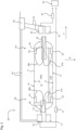
- FIG. 1 shows a hydrogen supply unit 10 according to a first preferred embodiment of the invention.
- the hydrogen supply unit 10 comprises a tank 11 which is configured to store in its interior 12 hydrogen (H2) in liquid state, i.e. as liquid hydrogen (LH2).
- an extraction chamber 13 is provided, which comprises at least one opening 15 or preferably a number of openings 15. The openings 15 are provided for extracting the liquid hydrogen from the interior 12 of tank 11 through the extraction chamber 13.
- At least one line or pipe 16 is connected to the extraction chamber 13 inside tank 11. It is configured for supplying the liquid hydrogen or LH2 from the tank 11 to a consumer unit 54 of the aircraft, for example to a propulsion unit, as indicated by arrow S in the figure.
- the hydrogen supply unit 10 e.g. comprises at least one pump connected to line 16.
- the pump may for example be arranged in the hydrogen supply unit 10 like or similarly to pump 31 or pump 32 shown in figure 2 which is described in detail further below.
- the extraction chamber 13 is attached to a wall 14 of tank 11, which is an inner tank wall in this example.
- the extraction chamber 13 may e.g. be configured as an extraction pod. It is preferably welded to the inner tank wall 14 or installed by other means close to the wall 14.
- extraction chamber 13 is mounted at or near the bottom 17 of tank 11 and positioned in a way that the openings 15 of extraction chamber 13 are located near or close above the bottom 17 of tank 11.
- the bottom 17 is formed by the inner side of the wall 14.
- the openings 15 of extraction chamber 13 are formed in a lower wall 29 of extraction chamber 13.
- the openings 15 are flat and positioned with a very small distance from to the bottom 17 formed by inner wall 14 of tank 11, in order to be as close as possible to a flush installation. That means, the openings 15 are located at a very low height above wall 14 of the tank 11.
- the openings 15 of extraction chamber or pod 13 may have the same surface area as line or pipe 16, in order to not produce an additional drag during LH2 extraction.
- the openings 15 are e.g. formed as slits.
- the line or pipe 16 connected to extraction chamber 13 extends through an outlet 18 provided in tank 11, which is preferably remotely located from the position where the extraction chamber 13 is installed.
- the outlet 18 is located at a forward end of the tank and/or at an aft end of tank 11, as it will be explained as an example further below with reference to Fig. 2 .
- Pipe 16 may e.g. further extend to a coldfinger.
- the hydrogen supply unit 10 comprises a tank 11 which is configured for storing hydrogen, in particular liquid hydrogen (LH2), in the interior 12 of tank 11.
- Tank 11 may e.g. be configured as described above with reference to Fig. 1 .
- a number of extraction chambers 23, 24, 25, 26 are provided in tank 11, each comprising one or more openings 15 for extracting the liquid hydrogen from the tank 11 through the respective extraction chamber, as described above with reference to Fig. 1 .
- the extraction chambers 23-26 are attached to the inner wall 14 of the tank 11 which surrounds its interior 12.
- Each extraction chamber 23, 24, 25, 26 is connected to an associated line 27a, 27b, 28a, 28b for supplying the liquid hydrogen (LH2) to the consumer unit 54 of the aircraft which is equipped with hydrogen supply unit 10.
- Each line 27a, 27b, 28a, 28b extending from the respective extraction chamber 23, 24, 25, 26 is connected via an assigned valve 41, 42, 43, 44 to a pump 31 or 32.
- the hydrogen supply unit 10 is configured for being mounted in an aircraft.
- the forward direction of the aircraft and of tank 11 is indicated by arrow F.
- Tank 11 comprises a rear or aft section 33 and a front or forward section 34 in accordance with the forward direction F of the aircraft in which the hydrogen supply unit 10 is mounted.
- All extraction chambers 23 to 26 are installed or welded to tank wall 14 which surrounds the interior 12 of the tank 11 in which the hydrogen is stored.
- the openings 15 are provided in the bottom 29 of the respective extraction chamber 23, 24, which is formed its lower wall.
- the openings are preferably provided in a way that they are facing the bottom wall 17 of tank 11, as described above with reference to Fig. 1 .
- the lower extraction chamber 23 is positioned in the rear section 33 of tank 11, while the other lower extraction chamber 24 is positioned in the front section 34 of tank 11.
- the upper extraction chamber 25 may be positioned in the rear section 33 of tank 11, while the other upper extraction chamber 26 may be positioned in the front section 34 of tank 11.
- Both extraction chambers 25, 26 are connected via their respective line 28a, 28b to their assigned valve 43 and 44 respectively, which are opened and closed during operation according to current attitudes and accelerations of the aircraft.
- a control unit 45 formed by a logics box is connected to the valves 41-44 by signal or data connections 53.
- the control unit 45 is configured for opening and closing the valves 41 to 44 depending on the current attitudes and accelerations of the aircraft in which the hydrogen supply unit 30 is provided.
- the logics box 45 receives the attitudes and accelerations of the aircraft via a data connection to the ADIRS (Air Data Inertial Reference System) of the aircraft. That means, the control unit or logics box 45 is configured for receiving data from the ADIRS in order to control the valves 41 to 44 depending on the received attitude and acceleration data.
- ADIRS Air Data Inertial Reference System
- a portion of the hydrogen within tank 11 is liquid hydrogen (LH2) and another portion of the hydrogen is gaseous hydrogen (GH2), wherein the GH2 is usually above the LH2.
- LH2 liquid hydrogen
- GH2 gaseous hydrogen
- the liquid hydrogen LH2 within tank 11 usually covers the lower extraction chambers or extraction pods 23, 24 mounted on or near the bottom 17 of tank 11.
- valves 41, 42 connected to the lines 27a, 27b extending from the lower extraction chambers 23, 24 covered by LH2 are opened according to the acceleration and attitude data received by control unit 45 from the ADIRS.
- Liquid hydrogen LH2 stored in tank 11 is extracted through at least one extraction chamber 13, 23, 24, 25, 26 provided in the tank 11 and attached to inner wall 14 of the tank.
- the extracted liquid hydrogen LH2 is supplied via at least one line 16, 27a, 27b, 28a, 28b and one or more pumps 31, 32 connected thereto from the one or more extraction chambers to a consumer unit 54 of the aircraft.
- the liquid hydrogen is preferably extracted at the different extraction positions where the extraction chambers 13, 23, 24, 25, 26 are located.
- the extraction positions in the tank 11 are varied or selected depending on the current attitude an acceleration of the aircraft.
- the liquid hydrogen contained in tank 11 covers the extraction chambers 23, 24 installed at the bottom 17 of tank 11.
- the valves 41, 42 assigned to extraction chambers 23 and 24 respectively, which are mounted at or near the bottom or lower wall 17 of tank 11, are opened, while the valves 43, 44 assigned to extraction chambers 25 and 26 respectively, which are mounted at or near the ceiling or upper wall 47 of tank 11, are closed and thus avoid an extraction of the gaseous hydrogen GH2 above the liquid hydrogen LH2 from the tank 11.
- one or more extraction chambers 25, 26 may be mounted near or at the ceiling 47 of tank 11.
- liquid hydrogen can be extracted as the extraction chambers or pods 25 and/or 26 positioned on or near the ceiling 47 can be used.
- the hydrogen supply unit 13 as shown in figure 2 with extraction chambers at different positions within tank 11 allow extraction in any aircraft attitude.
- tank 11 comprises a first outlet 51 in its rear or aft section 33, and a second outlet 52 in its front or forward section 34.
- first outlet 51 forms a rear or aft outlet
- second outlet 52 forms a front of forward outlet.
- outlets 51, 52 extend through polar mounts provided in the forward section 34 and the aft section 33 of tank 11. This allows a higher static pressure at the pumps 31, 32 than with an outlet only in the front section 34.
- the aft pump 31 is preferably positioned below and most preferably also behind the aft outlet 51 of tank 11.
- the front or forward pump 32 is preferably positioned below and most preferably further forward than the forward outlet 34 of tank 11.
- a specific advantage of this arrangement is that for example with the aircraft in climb, the aft outlet 51 is activated or can be activated, wherein the aft pump 31 is well below the tank 11.
- the hydrogen's static pressure supports the pump operation. This is especially supportive during TOGA (Take-Off/Go-Around) conditions, where the aircraft raises its angle of attack to get more lift.
- the tank 11 comprises only the forward outlet 52 as a single outlet, and all piping or lines 27, 28 are guided through that single forward outlet 52.
- the different positions of the extraction chambers 23-26 are kept as described above, in this example four positions.
- This configuration reduces the amount of pump head or static pressure.
- the specific advantage is that the number of throughputs in the tank 11 are reduced.
- the complete equipment comprising the pumps 31, 32 and/or the valves 41-44 is installed in the aft of the aircraft to raise the static pressure, as the aft or rear installation of the equipment is more helpful with a positive angle of attack, where the most pump performance and mass flow is needed.
- all piping or lines 27, 28 are guided through the single aft or rear outlet 51.
Landscapes
- Engineering & Computer Science (AREA)
- Mechanical Engineering (AREA)
- General Engineering & Computer Science (AREA)
- Aviation & Aerospace Engineering (AREA)
- Filling Or Discharging Of Gas Storage Vessels (AREA)
Abstract
Description
- The invention relates to a hydrogen supply unit for an aircraft. Further, the invention relates to a method of supplying liquid hydrogen in an aircraft. In addition, the invention relates to an aircraft.
- In particular, the invention can be applied in aircrafts such as airplanes, helicopters and other objects that can fly.
- Gas emissions having an impact on the climate have to be reduced. Particularly in aviation, a switch from conventional gas turbine engines to propulsion systems based on hydrogen (H2) has been identified as a growing market with a high number of aeroplanes in the next years and decades, in order to achieve zero emission flights. Many research institutes and companies have been searching for viable propulsion architectures to eliminate or reduce aircraft emissions for regional and larger aircrafts. In such aircrafts, the hydrogen is provided as liquid hydrogen (LH2) in a tank within the aircraft and supplied via pipes to the aircraft's propulsion engine and/or other consumer units of the aircraft.
- When supplying the LH2 to the aircraft's propulsion or other consumer unit, accidental feeding of the pipes with gaseous H2 (GH2) in the tank needs to be avoided. Further, the amount of unusable LH2 remaining in the tank after a maximum LH2 extraction shall be minimized.
- Therefore, it is the object of the invention to maximize utilization of the LH2 provided in an LH2 tank of an aircraft, and to prevent ingestion of gaseous hydrogen when liquid hydrogen from the tank is supplied to a consumer unit in the aircraft.
- According to a first aspect, the invention provides a hydrogen supply unit for an aircraft, comprising a tank for storing liquid hydrogen, an extraction chamber provided in the tank and comprising one or more openings for extracting the liquid hydrogen from the tank through the extraction chamber, at least one line connected to the extraction chamber and configured for supplying the liquid hydrogen to a consumer unit of the aircraft, and at least one pump connected to the line.
- Preferably, the extraction chamber is attached to a wall of the tank surrounding the hydrogen.
- Preferably, the openings are provided in the bottom of the extraction chamber.
- Preferably, the extraction chamber is mounted on or near the bottom or bottom wall of the tank so that the openings are close to the bottom of the tank.
- Preferably, two or more such extraction chambers are provided in the tank, wherein each extraction chamber is connected to an assigned valve.
- Preferably, each valve is connected to a control unit configured for opening and closing the valves depending on attitudes and accelerations of the aircraft.
- Preferably, the control unit is configured for receiving data from the air data inertial reference system (ADIRS) of an aircraft in order to control the valves.
- Preferably, each valve is provided in the respective line connected to the assigned extraction chamber.
- Preferably, at least one extraction chamber is located in a rear section of the tank.
- Preferably, at least one extraction chamber is located in a front section of the tank.
- Preferably, at least one extraction chamber is mounted at or near the ceiling of the tank.
- Preferably, at least a pair of extraction chambers is mounted at or near the ceiling of the tank, one of them being located in a rear section of the tank and one being located in a front section of the tank.
- Preferably, one or more lines or pipes extend from the one or more extraction chambers through an aft outlet provided in a rear section or end of the tank and/or through a forward outlet provided in a front section or front end of the tank.
- Preferably, one or more lines extend from the one or more extraction chambers exclusively through an aft outlet provided in a rear section or rear end of the tank.
- Preferably, one or more lines extend from the one or more extraction chambers exclusively through a forward outlet provided in a front section or front end of the tank.
- Preferably, the one or more pumps are configured for being positioned in the aircraft below and/or behind the aft outlet of the tank.
- Preferably, the one or more pumps are configured for being positioned below and/or in front of the forward outlet of the tank.
- According to a second aspect, the invention provides a method of supplying liquid hydrogen in an aircraft, comprising the steps: extracting liquid hydrogen from a tank of an aircraft through at least one extraction chamber provided in the tank and attached to an inner wall of the tank; and supplying the liquid hydrogen from the extraction chamber to a consumer unit of the aircraft.
- Preferably, the liquid hydrogen is extracted at different extracting positions which are selected depending on current attitudes and accelerations of the aircraft.
- Preferably, the hydrogen supply unit according to the invention is used when the method is performed.
- According to a third aspect, the invention provides an aircraft, characterized by a hydrogen supply unit according to the invention.
- Characteristics and advantages described in relation to the hydrogen supply unit are also related to the method of supplying liquid hydrogen, and vice versa.
- In the following, exemplary embodiments of the invention showing further characteristics and advantages are described in detail with reference to the figures, in which:
- Fig. 1
- shows a hydrogen supply unit according to a first preferred embodiment of the invention as a schematic sectional view; and
- Fig. 2
- shows a hydrogen supply unit according to a second preferred embodiment of the invention as a schematic sectional view.
-
Figure 1 shows ahydrogen supply unit 10 according to a first preferred embodiment of the invention. Thehydrogen supply unit 10 comprises atank 11 which is configured to store in its interior 12 hydrogen (H2) in liquid state, i.e. as liquid hydrogen (LH2). In thetank 11, anextraction chamber 13 is provided, which comprises at least one opening 15 or preferably a number ofopenings 15. Theopenings 15 are provided for extracting the liquid hydrogen from theinterior 12 oftank 11 through theextraction chamber 13. - At least one line or
pipe 16 is connected to theextraction chamber 13 insidetank 11. It is configured for supplying the liquid hydrogen or LH2 from thetank 11 to aconsumer unit 54 of the aircraft, for example to a propulsion unit, as indicated by arrow S in the figure. - The
hydrogen supply unit 10 e.g. comprises at least one pump connected toline 16. The pump may for example be arranged in thehydrogen supply unit 10 like or similarly to pump 31 orpump 32 shown infigure 2 which is described in detail further below. - The
extraction chamber 13 is attached to awall 14 oftank 11, which is an inner tank wall in this example. Theextraction chamber 13 may e.g. be configured as an extraction pod. It is preferably welded to theinner tank wall 14 or installed by other means close to thewall 14. - In this example,
extraction chamber 13 is mounted at or near thebottom 17 oftank 11 and positioned in a way that theopenings 15 ofextraction chamber 13 are located near or close above thebottom 17 oftank 11. Thebottom 17 is formed by the inner side of thewall 14. - In particular, the
openings 15 ofextraction chamber 13 are formed in alower wall 29 ofextraction chamber 13. Theopenings 15 are flat and positioned with a very small distance from to thebottom 17 formed byinner wall 14 oftank 11, in order to be as close as possible to a flush installation. That means, theopenings 15 are located at a very low height abovewall 14 of thetank 11. In particular, theopenings 15 of extraction chamber orpod 13 may have the same surface area as line orpipe 16, in order to not produce an additional drag during LH2 extraction. Theopenings 15 are e.g. formed as slits. - The line or
pipe 16 connected toextraction chamber 13 extends through anoutlet 18 provided intank 11, which is preferably remotely located from the position where theextraction chamber 13 is installed. Preferably, theoutlet 18 is located at a forward end of the tank and/or at an aft end oftank 11, as it will be explained as an example further below with reference toFig. 2 . Pipe 16 may e.g. further extend to a coldfinger. - Several
such extraction chambers 13 may be installed in a similar manner within theinterior 12 oftank 11. - In addition to
inner tank wall 14, the structure oftank 11 comprises anouter tank wall 19 in order to provide avacuum layer 21 between the inner tank wall and theouter tank wall 19. A multilayer insulation (MLI) 22 is preferably installed between theinner tank wall 14 and theouter tank wall 19. - Referring to
Figure 2 now, ahydrogen supply unit 30 according to a second preferred embodiment of the invention will be described. It may comprise a number of extraction chambers in a tank as described above - Also in this exemplary embodiment, the
hydrogen supply unit 10 comprises atank 11 which is configured for storing hydrogen, in particular liquid hydrogen (LH2), in theinterior 12 oftank 11.Tank 11 may e.g. be configured as described above with reference toFig. 1 . - A number of
extraction chambers tank 11, each comprising one ormore openings 15 for extracting the liquid hydrogen from thetank 11 through the respective extraction chamber, as described above with reference toFig. 1 . The extraction chambers 23-26 are attached to theinner wall 14 of thetank 11 which surrounds its interior 12. - Each
extraction chamber line consumer unit 54 of the aircraft which is equipped withhydrogen supply unit 10. Eachline respective extraction chamber valve pump - The
hydrogen supply unit 10 is configured for being mounted in an aircraft. The forward direction of the aircraft and oftank 11 is indicated by arrow F. -
Tank 11 comprises a rear oraft section 33 and a front orforward section 34 in accordance with the forward direction F of the aircraft in which thehydrogen supply unit 10 is mounted. - All
extraction chambers 23 to 26 are installed or welded totank wall 14 which surrounds the interior 12 of thetank 11 in which the hydrogen is stored. - In this preferred embodiment of the invention, one
pair tank 11 formed by itslower wall 17, so that therespective openings 15 of theextraction chambers lower tank wall 17 to allow extraction of the liquid hydrogen from there. In this way, these extraction chambers orpods - In particular, the
openings 15 are provided in the bottom 29 of therespective extraction chamber bottom wall 17 oftank 11, as described above with reference toFig. 1 . - Advantageously, the
lower extraction chamber 23 is positioned in therear section 33 oftank 11, while the otherlower extraction chamber 24 is positioned in thefront section 34 oftank 11. - Both
extraction chambers line valve - In addition to the
lower extraction chambers further extraction chamber extraction chambers ceiling 47 oftank 11. The extraction chambers orpods - The
upper extraction chamber 25 may be positioned in therear section 33 oftank 11, while the otherupper extraction chamber 26 may be positioned in thefront section 34 oftank 11. - Both
extraction chambers respective line valve - A
control unit 45 formed by a logics box is connected to the valves 41-44 by signal ordata connections 53. Thecontrol unit 45 is configured for opening and closing thevalves 41 to 44 depending on the current attitudes and accelerations of the aircraft in which thehydrogen supply unit 30 is provided. During operation, thelogics box 45 receives the attitudes and accelerations of the aircraft via a data connection to the ADIRS (Air Data Inertial Reference System) of the aircraft. That means, the control unit orlogics box 45 is configured for receiving data from the ADIRS in order to control thevalves 41 to 44 depending on the received attitude and acceleration data. - As shown in
Fig.2 , a portion of the hydrogen withintank 11 is liquid hydrogen (LH2) and another portion of the hydrogen is gaseous hydrogen (GH2), wherein the GH2 is usually above the LH2. When the aircraft and thus alsotank 11 is in horizontal orientation, the liquid hydrogen LH2 withintank 11 usually covers the lower extraction chambers orextraction pods tank 11. - In this situation, the
valves lines lower extraction chambers control unit 45 from the ADIRS. - As an example, a method of supplying liquid hydrogen in an aircraft is described in more detail the following with reference to
Figures 1 and2 :
Liquid hydrogen LH2 stored intank 11 is extracted through at least oneextraction chamber tank 11 and attached toinner wall 14 of the tank. The extracted liquid hydrogen LH2 is supplied via at least oneline more pumps consumer unit 54 of the aircraft. - If two or more extraction chambers are provided in
tank 11, the liquid hydrogen is preferably extracted at the different extraction positions where theextraction chambers tank 11 are varied or selected depending on the current attitude an acceleration of the aircraft. - For example, if the aircraft is on the ground or in horizontal orientation and not accelerated, the liquid hydrogen contained in
tank 11 covers theextraction chambers tank 11. In this case, thevalves extraction chambers lower wall 17 oftank 11, are opened, while thevalves extraction chambers upper wall 47 oftank 11, are closed and thus avoid an extraction of the gaseous hydrogen GH2 above the liquid hydrogen LH2 from thetank 11. - When the aircraft is climbing and/or accelerated, it may happen depending on the amount of liquid hydrogen in the
tank 11, that only theextraction chamber 23 provided in therear section 33 oftank 11 is covered by the liquid hydrogen LH2, as depicted inFig. 2 by theLH2 surface 48. Allother extraction chambers 24 to 26 are surrounded by gaseous hydrogen GH2 in that situation. - In this case, only the
valve 41 assigned to the rearlower extraction chamber 23 is opened, while theother valves tank 11 will be supplied to theconsumer unit 54 of the aircraft. - When the aircraft is descending or is accelerating negatively, it may happen depending on the amount of LH2 in
tank 11, that only thelower extraction chamber 24 located at or near the bottom 17 oftank 11 in itsfront section 34 is covered with liquid hydrogen, as indicated byLH2 surface 49 inFig. 2 . In this situation, allother extraction chambers valve 42 associated to the frontlower extraction chamber 24 is opened, while allother valves tank 11 will be supplied to theconsumer unit 54 of the aircraft. - Optionally, as described above, one or
more extraction chambers ceiling 47 oftank 11. - In this case, when an acceleration opposite to gravitational acceleration g is acting on the aircraft and on the
tank 11 mounted therein, it may happen that one or more of theupper extraction chambers ceiling 47 oftank 11 are surrounded by the liquid hydrogen LH2, while thelower extraction chambers valves chambers - That means, that even for a longer period of an acceleration acting on the aircraft which is opposite to the gravitational acceleration g, liquid hydrogen can be extracted as the extraction chambers or
pods 25 and/or 26 positioned on or near theceiling 47 can be used. - In particular, the
hydrogen supply unit 13 as shown infigure 2 with extraction chambers at different positions withintank 11 allow extraction in any aircraft attitude. - As shown in
Fig. 2 ,tank 11 comprises afirst outlet 51 in its rear oraft section 33, and asecond outlet 52 in its front orforward section 34. Thus, thefirst outlet 51 forms a rear or aft outlet, and thesecond outlet 52 forms a front of forward outlet. - In particular, the
outlets forward section 34 and theaft section 33 oftank 11. This allows a higher static pressure at thepumps front section 34. - The
aft pump 31 is preferably positioned below and most preferably also behind theaft outlet 51 oftank 11. The front orforward pump 32 is preferably positioned below and most preferably further forward than theforward outlet 34 oftank 11. - A specific advantage of this arrangement is that for example with the aircraft in climb, the
aft outlet 51 is activated or can be activated, wherein theaft pump 31 is well below thetank 11. Thus, the hydrogen's static pressure supports the pump operation. This is especially supportive during TOGA (Take-Off/Go-Around) conditions, where the aircraft raises its angle of attack to get more lift. - According to another embodiment which is not shown in the figures, the
tank 11 comprises only theforward outlet 52 as a single outlet, and all piping or lines 27, 28 are guided through that singleforward outlet 52. In this case, there is no aft tank outlet, but the different positions of the extraction chambers 23-26 are kept as described above, in this example four positions. This configuration reduces the amount of pump head or static pressure. However, the specific advantage is that the number of throughputs in thetank 11 are reduced. - As an alternative, the complete equipment comprising the
pumps rear outlet 51. -
- 10, 30
- hydrogen supply unit
- 11
- tank
- 12
- interior of tank
- 13
- extraction chamber or pod
- 14
- inner wall of tank
- 15
- openings
- 16
- line / pipe
- 17
- bottom or lower wall of tank
- 18
- outlet
- 19
- outer tank wall
- 21
- vacuum layer
- 22
- multilayer insulation / MLI
- 23, 24
- lower extraction chambers
- 25, 26
- upper extraction chambers
- 27a, 27b
- lines or pipes
- 28a, 28b
- lines or pipes
- 29
- bottom or lower wall of extraction chamber
- 31
- aft pump
- 32
- forward pump
- 33
- rear or aft section of tank
- 34
- front or forward section of tank
- LH2
- liquid hydrogen
- GH2
- gaseous hydrogen
- 41, 42
- valves
- 43,44
- valves
- 45
- control unit / logics box
- 47
- ceiling of tank
- 48
- LH2 surface when aircraft is climbing
- 49
- LH2 surface when aircraft is descending
- 51
- rear or aft outlet
- 52
- front or forward outlet
- 53
- signal connections
- 54
- consumer unit
- F
- forward direction of the aircraft
- g
- gravitational acceleration
Claims (10)
- Hydrogen supply unit (10, 30) for an aircraft, comprisinga tank (11) for storing liquid hydrogen (LH2),an extraction chamber (13; 23, 24, 25, 26) provided in the tank (11) and comprising one or more openings (15) for extracting the liquid hydrogen (LH2) from the tank (11) through the extraction chamber (13; 23, 24, 25, 26), at least one line (16; 27a, 27b, 28a, 28b) connected to the extraction chamber (13; 23, 24, 25, 26) and configured for supplying the liquid hydrogen (LH2) to a consumer unit (54) of the aircraft, andat least one pump (31, 32) connected to the line (16; 27a, 27b, 28a, 28b).
- Hydrogen supply unit according to claim 1, characterized in that the openings (15) are provided in the bottom (29) of the extraction chamber (13; 23, 24, 25, 26), wherein the extraction chamber (13; 23, 24) is mounted on or near the bottom (17) of the tank (11) so that the openings (15) are close to the bottom (17) of the tank (11).
- Hydrogen supply unit according to claim 1 or 2, characterized in that two or more such extraction chambers (13; 23, 24, 25, 26) are provided, wherein each extraction chamber (13; 23, 24, 25, 26) is connected to an assigned valve (41, 42, 43, 44), each valve (41, 42, 43, 44) being connected to a control unit (45) configured for opening and closing the valves (41, 42, 43, 44) depending on attitudes and accelerations of the aircraft.
- Hydrogen supply unit according to one of the preceding claims, characterized in that4.1. at least one extraction chamber (23, 25) is located in a rear section (33) of the tank (11), and at least one extraction chamber (24, 26) is located in a front section (34) of the tank (11); and/or4.2. at least one extraction chamber (25, 26) is mounted at or near the ceiling (47) of the tank (11); and/or4.3. at least a pair of extraction chambers (25, 26) is mounted at or near the ceiling (47) of the tank (11), one of them (25) being located in a rear section (33) of the tank (11) and one of them (26) being located in a front section (34) of the tank (11).
- Hydrogen supply unit according to one of the preceding claims, characterized in that the one or more lines (16; 27a, 27b, 28a, 28b) extend from the one or more extraction chambers (13; 23, 24, 25, 26)5.1. through an aft outlet (51) provided in a rear section (33) or end of the tank (11) and/or through a forward outlet (52) provided in a front section (34) or end of the tank (11); and or5.2. exclusively through an aft outlet (51) provided in a rear section (33) or end of the tank (11); and/or5.3. exclusively through a forward outlet (52) provided in a front section (34) or end of the tank (11).
- Hydrogen supply unit according to claim 5, characterized in that the one or more pumps (31, 32) are configured for being positioned in the aircraft6.1. below and/or behind the aft outlet (51) of the tank (11); and/or6.2. below and/or in front of the forward outlet (52) of the tank (11).
- Method of supplying liquid hydrogen in an aircraft, comprising the steps:a) extracting liquid hydrogen (LH2) from a tank (11) of an aircraft through at least one extraction chamber (13; 23, 24, 25, 26) provided in the tank (11) and attached to an inner wall (14) of the tank (11),b) supplying the liquid hydrogen (LH2) from the extraction chamber (13; 23, 24, 25, 26) to a consumer unit (54) of the aircraft.
- Method according to claim 7, characterized in that the liquid hydrogen (LH2) is extracted at different extracting positions which are selected depending on current attitudes and accelerations of the aircraft.
- Method according to claim 7 or 8, characterized in that the hydrogen supply unit (10; 30) according to one of claims 1 to 6 is used.
- Aircraft, characterized by a hydrogen supply unit (10; 30) according to one of claims 1 to 6
Priority Applications (3)
| Application Number | Priority Date | Filing Date | Title |
|---|---|---|---|
| EP23166095.2A EP4438493B1 (en) | 2023-03-31 | 2023-03-31 | Hydrogen supply unit for an aircraft, method of supplying liquid hydrogen in an aircraft, and aircraft |
| US18/619,730 US20240327025A1 (en) | 2023-03-31 | 2024-03-28 | Hydrogen supply unit for an aircraft, method of supplying liquid hydrogen in an aircraft, and aircraft |
| CN202410367736.6A CN118729156A (en) | 2023-03-31 | 2024-03-28 | Hydrogen supply unit for aircraft, method for supplying liquid hydrogen in aircraft, and aircraft |
Applications Claiming Priority (1)
| Application Number | Priority Date | Filing Date | Title |
|---|---|---|---|
| EP23166095.2A EP4438493B1 (en) | 2023-03-31 | 2023-03-31 | Hydrogen supply unit for an aircraft, method of supplying liquid hydrogen in an aircraft, and aircraft |
Publications (2)
| Publication Number | Publication Date |
|---|---|
| EP4438493A1 true EP4438493A1 (en) | 2024-10-02 |
| EP4438493B1 EP4438493B1 (en) | 2026-05-06 |
Family
ID=85800810
Family Applications (1)
| Application Number | Title | Priority Date | Filing Date |
|---|---|---|---|
| EP23166095.2A Active EP4438493B1 (en) | 2023-03-31 | 2023-03-31 | Hydrogen supply unit for an aircraft, method of supplying liquid hydrogen in an aircraft, and aircraft |
Country Status (3)
| Country | Link |
|---|---|
| US (1) | US20240327025A1 (en) |
| EP (1) | EP4438493B1 (en) |
| CN (1) | CN118729156A (en) |
Citations (7)
| Publication number | Priority date | Publication date | Assignee | Title |
|---|---|---|---|---|
| US6178991B1 (en) * | 1993-01-23 | 2001-01-30 | Helmut Schiwek | Safety container for potentially explosive and/or environmentally hazardous substances |
| EP1355107A2 (en) * | 2002-04-15 | 2003-10-22 | Deutsches Zentrum für Luft- und Raumfahrt e.V. | Pressure vessel |
| US20060014070A1 (en) * | 2003-06-27 | 2006-01-19 | Ultracell Corporation | Hydrogen fuel source refiller |
| US20080023493A1 (en) * | 2006-07-25 | 2008-01-31 | Lavan Charles K | Storage system for fuel cell gases |
| EP3176490A1 (en) * | 2015-12-02 | 2017-06-07 | The Boeing Company | Cryogenic tank and method of storing cryogenic liquids |
| DE102018215384A1 (en) * | 2018-09-11 | 2020-03-12 | Robert Bosch Gmbh | Tank device for storing a gaseous medium |
| EP3708896A1 (en) * | 2019-03-11 | 2020-09-16 | Siemens Mobility GmbH | Gas tank system, method for operating the gas tank system and train with gas tank system |
Family Cites Families (1)
| Publication number | Priority date | Publication date | Assignee | Title |
|---|---|---|---|---|
| US20240151358A1 (en) * | 2022-11-07 | 2024-05-09 | General Electric Company | Integrated cryogenic hydrogen tank systems and methods for operating the same |
-
2023
- 2023-03-31 EP EP23166095.2A patent/EP4438493B1/en active Active
-
2024
- 2024-03-28 CN CN202410367736.6A patent/CN118729156A/en active Pending
- 2024-03-28 US US18/619,730 patent/US20240327025A1/en active Pending
Patent Citations (7)
| Publication number | Priority date | Publication date | Assignee | Title |
|---|---|---|---|---|
| US6178991B1 (en) * | 1993-01-23 | 2001-01-30 | Helmut Schiwek | Safety container for potentially explosive and/or environmentally hazardous substances |
| EP1355107A2 (en) * | 2002-04-15 | 2003-10-22 | Deutsches Zentrum für Luft- und Raumfahrt e.V. | Pressure vessel |
| US20060014070A1 (en) * | 2003-06-27 | 2006-01-19 | Ultracell Corporation | Hydrogen fuel source refiller |
| US20080023493A1 (en) * | 2006-07-25 | 2008-01-31 | Lavan Charles K | Storage system for fuel cell gases |
| EP3176490A1 (en) * | 2015-12-02 | 2017-06-07 | The Boeing Company | Cryogenic tank and method of storing cryogenic liquids |
| DE102018215384A1 (en) * | 2018-09-11 | 2020-03-12 | Robert Bosch Gmbh | Tank device for storing a gaseous medium |
| EP3708896A1 (en) * | 2019-03-11 | 2020-09-16 | Siemens Mobility GmbH | Gas tank system, method for operating the gas tank system and train with gas tank system |
Also Published As
| Publication number | Publication date |
|---|---|
| EP4438493B1 (en) | 2026-05-06 |
| CN118729156A (en) | 2024-10-01 |
| US20240327025A1 (en) | 2024-10-03 |
Similar Documents
| Publication | Publication Date | Title |
|---|---|---|
| RU2578843C2 (en) | Systems and methods for maintenance of compliance with requirements to structural load of aircraft extra fuel tank | |
| EP2114766B1 (en) | Aircraft fuel tanks, systems and methods for increasing an aircraft's on-board fuel capacity | |
| EP3109165B1 (en) | Continuous fuel tank level control | |
| US8881764B2 (en) | Offset ambient level fuel feed system | |
| US8172182B2 (en) | Aircraft spillover fuel tank | |
| EP1591359B1 (en) | Aircraft and fuel venting system therefor | |
| US12104559B1 (en) | Vapor retention device | |
| US2953156A (en) | Fuel transfer system | |
| US20080173763A1 (en) | Fuel jettison system | |
| US12017789B2 (en) | Onboard liquid hydrogen storage for a hydrogen aircraft | |
| CN107336838A (en) | Oil tank for unmanned aerial vehicle | |
| CN112344807A (en) | Carrier rocket | |
| US2961130A (en) | Fuel booster pumps | |
| US11958625B1 (en) | Aerodynamic hydrogen tanks | |
| EP4438493B1 (en) | Hydrogen supply unit for an aircraft, method of supplying liquid hydrogen in an aircraft, and aircraft | |
| US9090356B2 (en) | System and method for reduced flammability of an aircraft fuel system | |
| EP4530195B1 (en) | Aircraft tank device for increasing a flight range and a wing area of an aircraft as well as aircraft | |
| EP4477558A1 (en) | An aircraft fuselage section | |
| Goraj et al. | Aircraft fuel systems and their influence on stability margin | |
| EP2293982B1 (en) | Fuel jettison system | |
| US20260126007A1 (en) | Gas turbine engine for an aircraft | |
| RU2028969C1 (en) | Flying vehicle fuel system | |
| RU2693091C2 (en) | Multi-stage missile and method of separating used parts | |
| Habibullah | AUTOMATION OF AIRCRAFT FUEL DISTRIBUTION SYSTEM | |
| Sandford et al. | Adaptation of the Saturn S-II for Ground-Launch Stage |
Legal Events
| Date | Code | Title | Description |
|---|---|---|---|
| PUAI | Public reference made under article 153(3) epc to a published international application that has entered the european phase |
Free format text: ORIGINAL CODE: 0009012 |
|
| STAA | Information on the status of an ep patent application or granted ep patent |
Free format text: STATUS: THE APPLICATION HAS BEEN PUBLISHED |
|
| AK | Designated contracting states |
Kind code of ref document: A1 Designated state(s): AL AT BE BG CH CY CZ DE DK EE ES FI FR GB GR HR HU IE IS IT LI LT LU LV MC ME MK MT NL NO PL PT RO RS SE SI SK SM TR |
|
| STAA | Information on the status of an ep patent application or granted ep patent |
Free format text: STATUS: REQUEST FOR EXAMINATION WAS MADE |
|
| 17P | Request for examination filed |
Effective date: 20250305 |
|
| GRAP | Despatch of communication of intention to grant a patent |
Free format text: ORIGINAL CODE: EPIDOSNIGR1 |
|
| STAA | Information on the status of an ep patent application or granted ep patent |
Free format text: STATUS: GRANT OF PATENT IS INTENDED |
|
| RIC1 | Information provided on ipc code assigned before grant |
Ipc: B64D 37/08 20060101AFI20251120BHEP Ipc: F17C 7/02 20060101ALI20251120BHEP |
|
| INTG | Intention to grant announced |
Effective date: 20251203 |
|
| GRAS | Grant fee paid |
Free format text: ORIGINAL CODE: EPIDOSNIGR3 |
|
| GRAA | (expected) grant |
Free format text: ORIGINAL CODE: 0009210 |
|
| STAA | Information on the status of an ep patent application or granted ep patent |
Free format text: STATUS: THE PATENT HAS BEEN GRANTED |
|
| AK | Designated contracting states |
Kind code of ref document: B1 Designated state(s): AL AT BE BG CH CY CZ DE DK EE ES FI FR GB GR HR HU IE IS IT LI LT LU LV MC ME MK MT NL NO PL PT RO RS SE SI SK SM TR |
|
| REG | Reference to a national code |
Ref country code: CH Ref legal event code: F10 Free format text: ST27 STATUS EVENT CODE: U-0-0-F10-F00 (AS PROVIDED BY THE NATIONAL OFFICE) Effective date: 20260506 Ref country code: GB Ref legal event code: FG4D |