EP4438483A1 - Optical imaging device degradation check - Google Patents
Optical imaging device degradation check Download PDFInfo
- Publication number
- EP4438483A1 EP4438483A1 EP24165096.9A EP24165096A EP4438483A1 EP 4438483 A1 EP4438483 A1 EP 4438483A1 EP 24165096 A EP24165096 A EP 24165096A EP 4438483 A1 EP4438483 A1 EP 4438483A1
- Authority
- EP
- European Patent Office
- Prior art keywords
- optical detector
- signal
- recited
- degradation
- return
- Prior art date
- Legal status (The legal status is an assumption and is not a legal conclusion. Google has not performed a legal analysis and makes no representation as to the accuracy of the status listed.)
- Pending
Links
Images

Classifications
-
- B—PERFORMING OPERATIONS; TRANSPORTING
- B64—AIRCRAFT; AVIATION; COSMONAUTICS
- B64D—EQUIPMENT FOR FITTING IN OR TO AIRCRAFT; FLIGHT SUITS; PARACHUTES; ARRANGEMENT OR MOUNTING OF POWER PLANTS OR PROPULSION TRANSMISSIONS IN AIRCRAFT
- B64D15/00—De-icing or preventing icing on exterior surfaces of aircraft
- B64D15/20—Means for detecting icing or initiating de-icing
-
- G—PHYSICS
- G01—MEASURING; TESTING
- G01S—RADIO DIRECTION-FINDING; RADIO NAVIGATION; DETERMINING DISTANCE OR VELOCITY BY USE OF RADIO WAVES; LOCATING OR PRESENCE-DETECTING BY USE OF THE REFLECTION OR RERADIATION OF RADIO WAVES; ANALOGOUS ARRANGEMENTS USING OTHER WAVES
- G01S7/00—Details of systems according to groups G01S13/00, G01S15/00, G01S17/00
- G01S7/48—Details of systems according to groups G01S13/00, G01S15/00, G01S17/00 of systems according to group G01S17/00
- G01S7/483—Details of pulse systems
- G01S7/486—Receivers
- G01S7/4861—Circuits for detection, sampling, integration or read-out
-
- G—PHYSICS
- G01—MEASURING; TESTING
- G01S—RADIO DIRECTION-FINDING; RADIO NAVIGATION; DETERMINING DISTANCE OR VELOCITY BY USE OF RADIO WAVES; LOCATING OR PRESENCE-DETECTING BY USE OF THE REFLECTION OR RERADIATION OF RADIO WAVES; ANALOGOUS ARRANGEMENTS USING OTHER WAVES
- G01S17/00—Systems using the reflection or reradiation of electromagnetic waves other than radio waves, e.g. lidar systems
- G01S17/02—Systems using the reflection of electromagnetic waves other than radio waves
- G01S17/04—Systems determining the presence of a target
-
- G—PHYSICS
- G01—MEASURING; TESTING
- G01S—RADIO DIRECTION-FINDING; RADIO NAVIGATION; DETERMINING DISTANCE OR VELOCITY BY USE OF RADIO WAVES; LOCATING OR PRESENCE-DETECTING BY USE OF THE REFLECTION OR RERADIATION OF RADIO WAVES; ANALOGOUS ARRANGEMENTS USING OTHER WAVES
- G01S17/00—Systems using the reflection or reradiation of electromagnetic waves other than radio waves, e.g. lidar systems
- G01S17/88—Lidar systems specially adapted for specific applications
-
- G—PHYSICS
- G01—MEASURING; TESTING
- G01S—RADIO DIRECTION-FINDING; RADIO NAVIGATION; DETERMINING DISTANCE OR VELOCITY BY USE OF RADIO WAVES; LOCATING OR PRESENCE-DETECTING BY USE OF THE REFLECTION OR RERADIATION OF RADIO WAVES; ANALOGOUS ARRANGEMENTS USING OTHER WAVES
- G01S7/00—Details of systems according to groups G01S13/00, G01S15/00, G01S17/00
- G01S7/48—Details of systems according to groups G01S13/00, G01S15/00, G01S17/00 of systems according to group G01S17/00
- G01S7/481—Constructional features, e.g. arrangements of optical elements
- G01S7/4811—Constructional features, e.g. arrangements of optical elements common to transmitter and receiver
-
- G—PHYSICS
- G01—MEASURING; TESTING
- G01N—INVESTIGATING OR ANALYSING MATERIALS BY DETERMINING THEIR CHEMICAL OR PHYSICAL PROPERTIES
- G01N21/00—Investigating or analysing materials by the use of optical means, i.e. using sub-millimetre waves, infrared, visible or ultraviolet light
- G01N21/01—Arrangements or apparatus for facilitating the optical investigation
- G01N21/15—Preventing contamination of the components of the optical system or obstruction of the light path
- G01N2021/155—Monitoring cleanness of window, lens, or other parts
- G01N2021/157—Monitoring by optical means
-
- G—PHYSICS
- G01—MEASURING; TESTING
- G01S—RADIO DIRECTION-FINDING; RADIO NAVIGATION; DETERMINING DISTANCE OR VELOCITY BY USE OF RADIO WAVES; LOCATING OR PRESENCE-DETECTING BY USE OF THE REFLECTION OR RERADIATION OF RADIO WAVES; ANALOGOUS ARRANGEMENTS USING OTHER WAVES
- G01S7/00—Details of systems according to groups G01S13/00, G01S15/00, G01S17/00
- G01S7/48—Details of systems according to groups G01S13/00, G01S15/00, G01S17/00 of systems according to group G01S17/00
- G01S7/497—Means for monitoring or calibrating
- G01S2007/4975—Means for monitoring or calibrating of sensor obstruction by, e.g. dirt- or ice-coating, e.g. by reflection measurement on front-screen
Definitions
- the present disclosure relates to optical imaging devices, and more particularly to monitoring optical imaging devices for degradation.
- Optical sensors such as used in optical ice detectors, need a method for determining if the signal is degraded.
- Potential sources of optical sensor degradation include contamination or damage to the window through which the optical sensor views its field of view, or by reduced functionality of the components of the optical sensor itself.
- a method includes checking an optical detector with a field of view for degradation by: directing the optical detector to a surface of an object in the field of view, wherein the surface is positioned at a given distance from the optical detector, and wherein the surface has a known reflectance; detecting an optical return from the surface with the optical detector to generate a return signal; and determining whether the return signal is representative of a degraded signal.
- the method includes outputting an alert for maintenance action if the return signal is indicative of a degraded signal.
- Degradation can include contamination on a window through which the optical detector views the field of view.
- the maintenance action can include replacing the window or clearing the window of contamination.
- Degradation can include a scratch on a lens of the optical detector.
- the maintenance can includes replacing the lens.
- Degradation can include one or more degraded photodiodes of the optical detector.
- the maintenance can include replacement of the one or more degraded photodiodes.
- the optical detector and the surface can both be aboard a vehicle.
- the optical detector can be an optical ice detector mounted on a side of an aircraft.
- the surface can be on a winglet or engine nacelle of the aircraft.
- the optical detector can be aboard an aircraft, and the surface can be a surface of a garage, hangar, airport terminal, or portable device at an airport terminal.
- Checking an optical detector with a field of view for degradation can be repeated regularly until there is a return signal indicative of a degraded signal.
- the optical detector and the surface can be arranged so the surface is always in the field of view.
- the method can include using range-gating to ignore the return from the surface when not performing the degradation check.
- the method can include moving the field of view of the optical detector to include the surface prior to checking the optical detector, and moving the field of view after checking to a field of view that does not include the surface.
- the method can include, prior to checking the optical detector, determining whether atmospheric conditions permit checking the optical detector.
- Fig. 1 a partial view of an embodiment of a system in accordance with the disclosure is shown in Fig. 1 and is designated generally by reference character 100.
- Figs. 2 Other embodiments of systems in accordance with the disclosure, or aspects thereof, are provided in Figs. 2 , as will be described.
- the systems and methods described herein can be used to check optical detectors, such as optical ice detectors aboard aircraft or other types of optical detectors, for degradation of performance.
- the system 100 includes an optical detector 102, which is aboard an aircraft 104.
- the optical detector 102 can be aboard any suitable vehicle or platform without departing from the scope of this disclosure.
- the optical detector 102 has a field of view 106 indicated schematically in Fig. 1 as a cone.
- a method includes checking the optical detector 102 for degradation by directing the optical detector 102 to a surface 108 of an object, e.g. a surface of the winglet of the aircraft 104, that is in the field of view 106.
- the surface 108 is positioned at a given distance from the optical detector 102. The given distance should be consistent or constant even if not precisely known, to allow for comparison of a signal to an expected value.
- the surface 108 has a known reflectance. Directing the optical detector 102 can include actively emitting a laser beam 112 from a laser emitter 116, labeled in Fig. 2 , toward the surface 108.
- the method includes detecting an optical return 110 (labeled in Fig. 2 ) from the surface 108 with the optical detector 102, e.g. with a photodiode 114, array of photodiodes, or other suitable photodetectors, to generate a return signal 118, indicated schematically in Fig. 2 .
- the method includes determining whether the return signal is representative of a degraded signal, which includes comparing the return signal 118 with an expected return signal, as indicated in Fig. 2 with box 120.
- the expected return signal can be an ideal signal stored in memory 122 in the optical detector 102. Checking an optical detector with a field of view for degradation is repeated regularly, e.g. once per flight for an aircraft, until there is a return signal indicative of a degraded signal at which point a maintenance alert can be outputted as described below.
- the expected return signal can be an historical signal return from the surface 108 over time. Multiple historical return signals can be stored in the memory 122 of the optical detector 102 to allow for monitoring trends in the return signals.
- the method includes outputting an alert for maintenance action if the return signal is indicative of a degraded signal, as indicated in Fig. 2 with the box 124.
- the alert output can be a message sent to the cockpit, ground crew, a data center, or the like, where maintenance can be ordered. For instance, if the degradation includes contamination on the window 126 through which the optical detector 102 views the field of view 106, the maintenance action includes replacing the window 126 or clearing the window 126 of contamination. If the degradation includes a scratch on a lens 128 of the optical detector 102, the maintenance includes replacing or repairing the lens 128. If the degradation includes one or more degraded photodiodes 114 of the optical detector 102, the maintenance includes replacement of the one or more degraded photodiodes 114.
- the method can account for variation in the surface 108, and or atmospheric conditions.
- the optical detector 102 running the methods disclosed herein can determine if signal degradation is due to degradation of the surface 108 by outputting an alert to service the surface 108 itself.
- the maintenance can include cleaning, refinishing, or replacing the surface 108.
- the optical detector 102 can repeat the check after servicing the surface 108 to see if the return signal is still representative of a degraded signal and if so, outputting an alert for a new maintenance action other than servicing the surface 108, as appropriate.
- the method can include tolerancing of acceptable signal return limits for degradation of the surface 108 over time.
- the optical detector 102 can be an optical ice detector, or any other suitable optical device, mounted on a side of an aircraft 104 or other vehicle or platform.
- the surface 108 is described above as being a surface of a winglet of the aircraft 104. However, any other suitable surface will also suffice, such as a surface of an engine nacelle 130 of the aircraft 104. If the optical detector 102 runs its check once per flight while on the ground between flights, the surface can be a surface of a garage or hangar 132, airport terminal 134, or portable device such as aboard a service vehicle or tool 136 at an airport terminal 134.
- the optical detector 102 and the surface 108 are arranged so the surface 108 is always in the field of view 106.
- the optical detector 102 can use range-gating to ignore the return from the surface 108 when not performing the degradation check. For instance, if the degradation check is performed for the winglet surface 108 or a surface of the nacelle 130 or other surface of the aircraft 104, that surface can be ignored while the optical detector 102 is performing its main duties, e.g. ice detection, during a flight by using range-gating.
- the method can include moving the field of view 106 of the optical detector 102, as indicated by the double arrows in Fig.
- the optical detector 108 can move its field of view to not include the surface 108 for resuming normal duties, such as ice detection.
- the optical detector 102 can move its field of view 106 using any suitable movement device such as a rotating optical wedge 138, labeled in Fig. 2 , covering the aperture of the sensor, e.g. the aperture of the photodiode or array of photodiodes 114, and of the laser emitter 116 to point at the known surface 108 only when performing the degradation check.
- the method can also include, prior to checking the optical detector 102, determining whether atmospheric conditions permit checking the optical detector.
- the degradation check need only be performed only when no precipitation or clouds are present to interfere with the degradation check.
Landscapes
- Engineering & Computer Science (AREA)
- Physics & Mathematics (AREA)
- Computer Networks & Wireless Communication (AREA)
- General Physics & Mathematics (AREA)
- Radar, Positioning & Navigation (AREA)
- Remote Sensing (AREA)
- Electromagnetism (AREA)
- Aviation & Aerospace Engineering (AREA)
- Photometry And Measurement Of Optical Pulse Characteristics (AREA)
Abstract
A method includes checking an optical detector (102) with a field of view for degradation by: directing the optical detector (102) to a surface of an object in the field of view, wherein the surface is positioned at a given distance from the optical detector (102), and wherein the surface has a known reflectance; detecting an optical return from the surface with the optical detector (102) to generate a return signal; and determining whether the return signal is representative of a degraded signal. The method includes outputting an alert for maintenance action if the return signal is indicative of a degraded signal.
Description
- The present disclosure relates to optical imaging devices, and more particularly to monitoring optical imaging devices for degradation.
- Optical sensors, such as used in optical ice detectors, need a method for determining if the signal is degraded. Potential sources of optical sensor degradation include contamination or damage to the window through which the optical sensor views its field of view, or by reduced functionality of the components of the optical sensor itself.
- The conventional techniques have been considered satisfactory for their intended purpose. However, there is an ever present need for improved systems and methods for checking optical sensors for degradation. This disclosure provides a solution for this need.
- A method includes checking an optical detector with a field of view for degradation by: directing the optical detector to a surface of an object in the field of view, wherein the surface is positioned at a given distance from the optical detector, and wherein the surface has a known reflectance; detecting an optical return from the surface with the optical detector to generate a return signal; and determining whether the return signal is representative of a degraded signal. The method includes outputting an alert for maintenance action if the return signal is indicative of a degraded signal.
- Degradation can include contamination on a window through which the optical detector views the field of view. The maintenance action can include replacing the window or clearing the window of contamination. Degradation can include a scratch on a lens of the optical detector. The maintenance can includes replacing the lens. Degradation can include one or more degraded photodiodes of the optical detector. The maintenance can include replacement of the one or more degraded photodiodes.
- Determining whether the return signal is representative of a degraded signal can include comparing the return signal with an expected return signal. Checking an optical detector with a field of view for degradation can be repeated regularly until there is a return signal indicative of a degraded signal. Determining whether the signal is representative of a degraded signal can include comparing the return signal with an historical signal return from the surface over time.
- Determining whether the return signal is representative of a degraded signal can include determining if signal degradation is due to degradation of the surface by outputting an alert to service the surface and repeating checking the optical detector after servicing the surface to see if the return signal is still representative of a degraded signal and if so, outputting an alert for maintenance action other than servicing the surface. Determining whether the return signal is representative of a degraded signal can include tolerancing of acceptable signal return limits for degradation of the surface over time.
- The optical detector and the surface can both be aboard a vehicle. The optical detector can be an optical ice detector mounted on a side of an aircraft. The surface can be on a winglet or engine nacelle of the aircraft. The optical detector can be aboard an aircraft, and the surface can be a surface of a garage, hangar, airport terminal, or portable device at an airport terminal.
- Checking an optical detector with a field of view for degradation can be repeated regularly until there is a return signal indicative of a degraded signal. The optical detector and the surface can be arranged so the surface is always in the field of view. The method can include using range-gating to ignore the return from the surface when not performing the degradation check. The method can include moving the field of view of the optical detector to include the surface prior to checking the optical detector, and moving the field of view after checking to a field of view that does not include the surface. The method can include, prior to checking the optical detector, determining whether atmospheric conditions permit checking the optical detector.
- These and other features of the systems and methods of the subject disclosure will become more readily apparent to those skilled in the art from the following detailed description of the preferred embodiments taken in conjunction with the drawings.
- So that those skilled in the art to which the subject disclosure appertains will readily understand how to make and use the devices and methods of the subject disclosure without undue experimentation, preferred embodiments thereof will be described in detail herein below with reference to certain figures, wherein:
-
Fig. 1 is a schematic perspective view of an embodiment of a system constructed in accordance with the present disclosure, showing an aircraft with an optical detector with various surfaces that can be used for checking the optical detector for degradation; and -
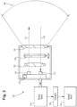
Fig. 2 is a schematic view of the optical detector ofFig. 1 , showing components that can be checked for degradation. - Reference will now be made to the drawings wherein like reference numerals identify similar structural features or aspects of the subject disclosure. For purposes of explanation and illustration, and not limitation, a partial view of an embodiment of a system in accordance with the disclosure is shown in
Fig. 1 and is designated generally byreference character 100. Other embodiments of systems in accordance with the disclosure, or aspects thereof, are provided inFigs. 2 , as will be described. The systems and methods described herein can be used to check optical detectors, such as optical ice detectors aboard aircraft or other types of optical detectors, for degradation of performance. - The
system 100 includes anoptical detector 102, which is aboard anaircraft 104. Those skilled in the art will readily appreciate that theoptical detector 102 can be aboard any suitable vehicle or platform without departing from the scope of this disclosure. Theoptical detector 102 has a field ofview 106 indicated schematically inFig. 1 as a cone. A method includes checking theoptical detector 102 for degradation by directing theoptical detector 102 to asurface 108 of an object, e.g. a surface of the winglet of theaircraft 104, that is in the field ofview 106. Thesurface 108 is positioned at a given distance from theoptical detector 102. The given distance should be consistent or constant even if not precisely known, to allow for comparison of a signal to an expected value. Thesurface 108 has a known reflectance. Directing theoptical detector 102 can include actively emitting alaser beam 112 from alaser emitter 116, labeled inFig. 2 , toward thesurface 108. The method includes detecting an optical return 110 (labeled inFig. 2 ) from thesurface 108 with theoptical detector 102, e.g. with aphotodiode 114, array of photodiodes, or other suitable photodetectors, to generate areturn signal 118, indicated schematically inFig. 2 . The method includes determining whether the return signal is representative of a degraded signal, which includes comparing thereturn signal 118 with an expected return signal, as indicated inFig. 2 withbox 120. The expected return signal can be an ideal signal stored inmemory 122 in theoptical detector 102. Checking an optical detector with a field of view for degradation is repeated regularly, e.g. once per flight for an aircraft, until there is a return signal indicative of a degraded signal at which point a maintenance alert can be outputted as described below. The expected return signal can be an historical signal return from thesurface 108 over time. Multiple historical return signals can be stored in thememory 122 of theoptical detector 102 to allow for monitoring trends in the return signals. - Reference is now made to
Fig. 2 . The method includes outputting an alert for maintenance action if the return signal is indicative of a degraded signal, as indicated inFig. 2 with thebox 124. The alert output can be a message sent to the cockpit, ground crew, a data center, or the like, where maintenance can be ordered. For instance, if the degradation includes contamination on thewindow 126 through which theoptical detector 102 views the field ofview 106, the maintenance action includes replacing thewindow 126 or clearing thewindow 126 of contamination. If the degradation includes a scratch on alens 128 of theoptical detector 102, the maintenance includes replacing or repairing thelens 128. If the degradation includes one or moredegraded photodiodes 114 of theoptical detector 102, the maintenance includes replacement of the one or moredegraded photodiodes 114. - With reference again to
Fig. 1 , the method can account for variation in thesurface 108, and or atmospheric conditions. Theoptical detector 102 running the methods disclosed herein can determine if signal degradation is due to degradation of thesurface 108 by outputting an alert to service thesurface 108 itself. For instance, the maintenance can include cleaning, refinishing, or replacing thesurface 108. Then theoptical detector 102 can repeat the check after servicing thesurface 108 to see if the return signal is still representative of a degraded signal and if so, outputting an alert for a new maintenance action other than servicing thesurface 108, as appropriate. Due to expected degradation of thesurface 108, the method can include tolerancing of acceptable signal return limits for degradation of thesurface 108 over time. - The
optical detector 102 can be an optical ice detector, or any other suitable optical device, mounted on a side of anaircraft 104 or other vehicle or platform. Thesurface 108 is described above as being a surface of a winglet of theaircraft 104. However, any other suitable surface will also suffice, such as a surface of anengine nacelle 130 of theaircraft 104. If theoptical detector 102 runs its check once per flight while on the ground between flights, the surface can be a surface of a garage orhangar 132,airport terminal 134, or portable device such as aboard a service vehicle ortool 136 at anairport terminal 134. - The
optical detector 102 and the surface 108 (or a surface of one of the other objects listed above) are arranged so thesurface 108 is always in the field ofview 106. Theoptical detector 102 can use range-gating to ignore the return from thesurface 108 when not performing the degradation check. For instance, if the degradation check is performed for thewinglet surface 108 or a surface of thenacelle 130 or other surface of theaircraft 104, that surface can be ignored while theoptical detector 102 is performing its main duties, e.g. ice detection, during a flight by using range-gating. The method can include moving the field ofview 106 of theoptical detector 102, as indicated by the double arrows inFig. 1 , to include the surface 108 (or other surface) prior to checking theoptical detector 102. After checking using thesurface 108, theoptical detector 108 can move its field of view to not include thesurface 108 for resuming normal duties, such as ice detection. Theoptical detector 102 can move its field ofview 106 using any suitable movement device such as a rotatingoptical wedge 138, labeled inFig. 2 , covering the aperture of the sensor, e.g. the aperture of the photodiode or array ofphotodiodes 114, and of thelaser emitter 116 to point at the knownsurface 108 only when performing the degradation check. The method can also include, prior to checking theoptical detector 102, determining whether atmospheric conditions permit checking the optical detector. Depending on characteristics of the device, it may need to account for atmospheric conditions such as fog or rain between thelens 128 and the target,e.g. surface 108. In the case of an optical ice detector, this condition is known by the sensing algorithms, so the degradation check need only be performed only when no precipitation or clouds are present to interfere with the degradation check. - The methods and systems of the present disclosure, as described above and shown in the drawings, provide for a check for optical detectors, such as optical ice detectors aboard aircraft or other types of optical detectors, for degradation of performance. While the apparatus and methods of the subject disclosure have been shown and described with reference to preferred embodiments, those skilled in the art will readily appreciate that changes and/or modifications may be made thereto without departing from the scope of the subject disclosure.
Claims (15)
- A method comprising:checking an optical detector (102) with a field of view for degradation by:directing the optical detector (102) to a surface of an object in the field of view, wherein the surface is positioned at a given distance from the optical detector (102), and wherein the surface has a known reflectance;detecting an optical return from the surface with the optical detector (102) to generate a return signal; anddetermining whether the return signal is representative of a degraded signal; andoutputting an alert for maintenance action if the return signal is indicative of a degraded signal.
- The method as recited in claim 1, wherein degradation includes contamination on a window through which the optical detector (102) views the field of view, and wherein the maintenance action includes replacing the window or clearing the window of contamination.
- The method as recited in any preceding claim, wherein degradation includes a scratch on a lens of the optical detector (102), and wherein the maintenance action includes replacing the lens.
- The method as recited in any preceding claim, wherein degradation includes one or more degraded photodiodes of the optical detector (102), wherein the maintenance action includes replacement of the one or more degraded photodiodes.
- The method as recited in any preceding claim, wherein determining whether the return signal is representative of a degraded signal includes comparing the return signal with an expected return signal.
- The method as recited in any preceding claim, wherein checking an optical detector (102) with a field of view for degradation is repeated regularly until there is a return signal indicative of a degraded signal.
- The method as recited in claim 6, wherein determining whether the signal is representative of a degraded signal includes comparing the return signal with an historical signal return from the surface over time.
- The method as recited in claim 7, wherein determining whether the return signal is representative of a degraded signal includes determining if signal degradation is due to degradation of the surface by outputting an alert to service the surface and repeating checking the optical detector (102) after servicing the surface to see if the return signal is still representative of a degraded signal and if so, outputting an alert for maintenance action other than servicing the surface.
- The method as recited in claim 7, wherein determining whether the return signal is representative of a degraded signal includes tolerancing of acceptable signal return limits for degradation of the surface over time.
- The method as recited in any preceding claim, wherein the optical detector (102) and the surface are both aboard a vehicle.
- The method as recited in any preceding claim, wherein the optical detector (102) is an optical ice detector mounted on a side of an aircraft, and wherein the surface is on a winglet or engine nacelle of the aircraft.
- The method as recited in any preceding claim, wherein the optical detector (102) is aboard an aircraft, and wherein the surface is a surface of a garage, hangar, airport terminal, or portable device at an airport terminal.
- The method as recited in any preceding claim, wherein checking an optical detector (102) with a field of view for degradation is repeated regularly until there is a return signal indicative of a degraded signal, and wherein the optical detector (102) and the surface are arranged so the surface is always in the field of view, and further comprising using range-gating to ignore the return from the surface when not performing the degradation check.
- The method as recited in any preceding claim, further comprising moving the field of view of the optical detector (102) to include the surface prior to checking the optical detector (102), and moving the field of view after checking to a field of view that does not include the surface.
- The method as recited in any preceding claim, further comprising, prior to checking the optical detector (102), determining whether atmospheric conditions permit checking the optical detector (102).
Applications Claiming Priority (1)
| Application Number | Priority Date | Filing Date | Title |
|---|---|---|---|
| US18/126,612 US20240329212A1 (en) | 2023-03-27 | 2023-03-27 | Optical imaging device degradation check |
Publications (1)
| Publication Number | Publication Date |
|---|---|
| EP4438483A1 true EP4438483A1 (en) | 2024-10-02 |
Family
ID=90417506
Family Applications (1)
| Application Number | Title | Priority Date | Filing Date |
|---|---|---|---|
| EP24165096.9A Pending EP4438483A1 (en) | 2023-03-27 | 2024-03-21 | Optical imaging device degradation check |
Country Status (2)
| Country | Link |
|---|---|
| US (1) | US20240329212A1 (en) |
| EP (1) | EP4438483A1 (en) |
Citations (4)
| Publication number | Priority date | Publication date | Assignee | Title |
|---|---|---|---|---|
| US6069565A (en) * | 1992-10-20 | 2000-05-30 | Rosemount Aerospace Inc. | System for detecting ice or snow on surface which specularly reflects light |
| US8397339B2 (en) * | 2008-10-14 | 2013-03-19 | Kabushiki Kaisha Toshiba | Reference member cleaning device, and reference member cleaning method |
| US20190377073A1 (en) * | 2018-06-08 | 2019-12-12 | Fanuc Corporation | Distance-measuring apparatus with polarizing filter |
| EP3397947B1 (en) * | 2015-12-31 | 2020-04-29 | Gen-Probe Incorporated | Systems for analyzing a sample and for monitoring the performance of an optical signal detector |
Family Cites Families (12)
| Publication number | Priority date | Publication date | Assignee | Title |
|---|---|---|---|---|
| US7783403B2 (en) * | 1994-05-23 | 2010-08-24 | Automotive Technologies International, Inc. | System and method for preventing vehicular accidents |
| US6052056A (en) * | 1996-04-26 | 2000-04-18 | Icg Technologies, Llc | Substance detection system and method |
| US6755653B2 (en) * | 2001-10-25 | 2004-06-29 | Cubic Defense Systems, Inc. | System and method for preventing cheating in a simulated combat exercise |
| US7312713B2 (en) * | 2004-12-17 | 2007-12-25 | Research Foundation Of The City University Of New York | Methods and systems for detection of ice formation on surfaces |
| US20170115215A1 (en) * | 2015-10-26 | 2017-04-27 | Jeffrey Scott Adler | Sensor for detecting remotely located reflective material |
| US9986233B1 (en) * | 2017-03-16 | 2018-05-29 | Amazon Technologies, Inc. | Camera calibration using fixed calibration targets |
| US10175167B2 (en) * | 2017-03-28 | 2019-01-08 | Te Connectivity Corporation | Optical sensor for detecting accumulation of a material |
| US11415685B2 (en) * | 2017-04-21 | 2022-08-16 | Hewlett-Packard Development Company, L.P. | Sensors calibration |
| US10611488B2 (en) * | 2017-05-05 | 2020-04-07 | Rosemount Aerospace Inc. | Ice accretion boundary locator |
| US11120538B2 (en) * | 2019-12-27 | 2021-09-14 | Zoox, Inc. | Sensor degradation detection and remediation |
| US12299077B2 (en) * | 2020-09-24 | 2025-05-13 | Intel Corporation | Perception system error detection and re-verification |
| US12103690B2 (en) * | 2020-11-05 | 2024-10-01 | United States Of America As Represented By The Secretary Of The Air Force | Ice detection and precautionary system shut-down event reduction systems and related methods |
-
2023
- 2023-03-27 US US18/126,612 patent/US20240329212A1/en active Pending
-
2024
- 2024-03-21 EP EP24165096.9A patent/EP4438483A1/en active Pending
Patent Citations (4)
| Publication number | Priority date | Publication date | Assignee | Title |
|---|---|---|---|---|
| US6069565A (en) * | 1992-10-20 | 2000-05-30 | Rosemount Aerospace Inc. | System for detecting ice or snow on surface which specularly reflects light |
| US8397339B2 (en) * | 2008-10-14 | 2013-03-19 | Kabushiki Kaisha Toshiba | Reference member cleaning device, and reference member cleaning method |
| EP3397947B1 (en) * | 2015-12-31 | 2020-04-29 | Gen-Probe Incorporated | Systems for analyzing a sample and for monitoring the performance of an optical signal detector |
| US20190377073A1 (en) * | 2018-06-08 | 2019-12-12 | Fanuc Corporation | Distance-measuring apparatus with polarizing filter |
Also Published As
| Publication number | Publication date |
|---|---|
| US20240329212A1 (en) | 2024-10-03 |
Similar Documents
| Publication | Publication Date | Title |
|---|---|---|
| CN108802743B (en) | Light Detection and Ranging LIDAR Ice Detection System | |
| US8724099B2 (en) | Airborne LIDAR for detecting matter suspended in air | |
| CN103576159B (en) | A kind of runway road surface checking device based on laser scanner technique and method | |
| JP6517453B1 (en) | Optimization of the range of the aircraft docking system | |
| US10207810B2 (en) | Optically detecting cloud metrics using sampled analog measurements of light reflection | |
| US9096323B1 (en) | Window contamination sensor for optical detection systems | |
| WO2006016075A1 (en) | System for measurement of projected turbulence downwind of an aircraft | |
| US20200160736A1 (en) | Determination of a pavement state from on-board measurements of pavement contamination, associated system and aircraft | |
| CN112198499B (en) | Airport runway foreign matter monitoring system based on thing networking | |
| US20240329212A1 (en) | Optical imaging device degradation check | |
| US20230152431A1 (en) | Methods for Detecting LIDAR Aperture Fouling | |
| CN117031496A (en) | Anti-external-damage monitoring system and method based on laser radar space measurement technology | |
| CN117572440A (en) | Airport runway foreign matter detection method and device and electronic equipment | |
| US12487088B2 (en) | Airborne measurement system comprising a SPAD camera | |
| FR2938922A1 (en) | METHOD AND DEVICE FOR OPTIMIZING THE ORIENTATION OF A LASER ANEMOMETER ON AN AIRCRAFT | |
| EP3147688B1 (en) | Method for detecting obstacles and vehicle provided with an obstacle-detection system | |
| CN111897025A (en) | Airport pavement foreign matter detection equipment and system based on 3D/2D integration detection | |
| EP4286885B1 (en) | Method and system for continuous in-flight management of an on-board beam generator | |
| US20250383431A1 (en) | System having photodetector and processor for determining ocurrence of contamination on window surface and method therefor | |
| CN121578328A (en) | Laser atmosphere data system | |
| WO2025201628A1 (en) | Collision alert system for warning of collision-critical objects, in particular for warning of debris and/or birds, in the flight path of an aircraft, aircraft fleet and collision warning method | |
| US20250044804A1 (en) | Air vehicle control system, air vehicle control device, remote control device, air vehicle, air vehicle control method, and air vehicle control program | |
| FR3155815A1 (en) | Aircraft guidance system and associated guidance method | |
| CN121920989A (en) | Intelligent inspection system for power transmission lines based on air-space-ground communication | |
| CN121049869A (en) | Automatic Method and System for Airport Dominant Visibility Measurement Based on 3D LiDAR |
Legal Events
| Date | Code | Title | Description |
|---|---|---|---|
| PUAI | Public reference made under article 153(3) epc to a published international application that has entered the european phase |
Free format text: ORIGINAL CODE: 0009012 |
|
| STAA | Information on the status of an ep patent application or granted ep patent |
Free format text: STATUS: THE APPLICATION HAS BEEN PUBLISHED |
|
| AK | Designated contracting states |
Kind code of ref document: A1 Designated state(s): AL AT BE BG CH CY CZ DE DK EE ES FI FR GB GR HR HU IE IS IT LI LT LU LV MC ME MK MT NL NO PL PT RO RS SE SI SK SM TR |
|
| STAA | Information on the status of an ep patent application or granted ep patent |
Free format text: STATUS: REQUEST FOR EXAMINATION WAS MADE |
|
| 17P | Request for examination filed |
Effective date: 20250402 |
|
| STAA | Information on the status of an ep patent application or granted ep patent |
Free format text: STATUS: EXAMINATION IS IN PROGRESS |